Introduction
This document describes the use of the ping and traceroute commands on Cisco routers.
Prerequisites
Requirements
There are no specific requirements for this document.
Components Used
This document is not restricted to specific software and hardware versions.
The information in this document was created from the devices in a specific lab environment. All of the devices used in this document started with a cleared (default) configuration. If your network is live, ensure that you understand the potential impact of any command.
Conventions
For more information on document conventions, refer to the Cisco Technical Tips Conventions .
Background Information
Note: Any debug command used on a production router can cause serious problems. Read the Use the Debug Command section before you issue debug commands.
In this document, this basic configuration is used for examples in this article:
 Basic Configuration of IPs and Routers
The Ping Command
The ping command is a very common method used to troubleshoot accessibility of devices. It uses a series of Internet Control Message Protocol (ICMP) Echo messages to determine:
-
Whether a remote host is active or inactive.
-
The round-trip delay used to communicate with the host.
-
Packet loss.
The ping command first sends an echo request packet to an address, then waits for a reply. The ping is successful only if:
-
the echo request gets to the destination, and
-
the destination is able to get an echo reply back to the source within a predetermined time called a timeout. The default value of this timeout is two seconds on Cisco routers.
The TTL value of a ping packet cannot be changed.
This next code example shows the ping command after the debug ip packet detail command is enabled.
Warning: When the debug ip packet detail command is used on a production router it can cause high CPU utilization. This can result in a severe performance degradation or a network outage.
Router1#debug ip packet detail
IP packet debugging is on (detailed)

Router1#ping 172.16.0.12
Type escape sequence to abort.
Sending 5, 100-byte ICMP Echos to 172.16.0.12, timeout is 2 seconds:
!!!!!
Success rate is 100 percent (5/5), round-trip min/avg/max = 4/6/8 ms

Router1#
Jan 20 15:54:47.487: IP: s=172.16.12.1 (local), d=172.16.0.12 (Serial0), len 100,
  sending
Jan 20 15:54:47.491: ICMP type=8, code=0

!--- This is the ICMP packet 172.16.12.1 sent to 172.16.0.12.
!--- ICMP type=8 corresponds to the echo message.

Jan 20 15:54:47.523: IP: s=172.16.0.12 (Serial0), d=172.16.12.1 (Serial0), len 100,
  rcvd 3
Jan 20 15:54:47.527: ICMP type=0, code=0

!--- This is the answer we get from 172.16.0.12. !--- ICMP type=0 corresponds to the echo reply message.
!--- By default, the repeat count is five times, so there will be five
!--- echo requests, and five echo replies.
Possible ICMP-type Values
| ICMP Type | Literal |
|---|---|
| 0 | echo-reply |
| 3 | destination unreachable code 0 = net unreachable 1 = host unreachable 2 = protocol unreachable 3 = port unreachable 4 = fragmentation needed, and DF set 5 = source route failed |
| 4 | source-quench |
| 5 | redirect code 0 = redirect datagrams for the network 1 = redirect datagrams for the host 2 = redirect datagrams for the type of service and network 3 = redirect datagrams for the type of service and host |
| 6 | alternate-address |
| 8 | echo |
| 9 | router-advertisement |
| 10 | router-solicitation |
| 11 | time-exceeded code 0 = time to live exceeded in transit 1 = fragment reassembly time exceeded |
| 12 | parameter-problem |
| 13 | timestamp-request |
| 14 | timestamp-reply |
| 15 | information-request |
| 16 | information-reply |
| 17 | mask-request |
| 18 | mask-reply |
| 31 | conversion-error |
| 32 | mobile-redirect |
Possible Output Characters From the Ping Facility
| Character | Description |
|---|---|
| ! | Each exclamation point indicates receipt of a reply. |
| . | Each period indicates the network server timed out as it waits for a reply. |
| U | A destination unreachable error PDU was received. |
| Q | Source quench (destination too busy). |
| M | Could not fragment. |
| ? | Unknown packet type. |
| & | Packet lifetime exceeded. |
Unable to Ping
If you are not able to successfully ping to an IP address, consider the causes listed in this section.
Router Issue
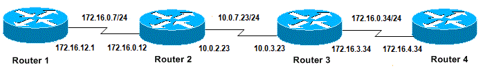
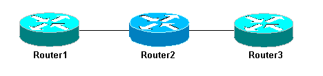
Here are examples of unsuccessful ping attempts, that can determine the problem, and what to do to resolve the problem. This example is shown with this network topology diagram:
 Router Issues
Router1#
!
interface Serial0
ip address 172.16.12.1 255.255.255.0
no fair-queue
clockrate 64000
!

Router2#
!
interface Serial0
ip address 10.0.2.23 255.255.255.0
no fair-queue
clockrate 64000
!
interface Serial1
ip address 172.16.0.12 255.255.255.0
!


Router3#
!
interface Serial0
ip address 172.16.3.34 255.255.255.0
no fair-queue
!
interface Serial1
ip address 10.0.3.23 255.255.255.0
!

Router4#
!
interface Serial0
ip address 172.16.4.34 255.255.255.0
no fair-queue
clockrate 64000
!
Try to ping Router4 from Router1:
Router1#ping 172.16.4.34

Type escape sequence to abort.
Sending 5, 100-byte ICMP Echos to 172.16.4.34, timeout is 2 seconds:
.....
Success rate is 0 percent (0/5)
Results:
Router1#debug ip packet
IP packet debugging is on
Warning: When the debug ip packet command is used on a production router it can cause high CPU utilization. This can result in a severe performance degradation or a network outage.
Router1#ping 172.16.4.34

Type escape sequence to abort.
Sending 5, 100-byte ICMP Echos to 172.16.4.34, timeout is 2 seconds:

Jan 20 16:00:25.603: IP: s=172.16.12.1 (local), d=172.16.4.34, len 100, unroutable.
Jan 20 16:00:27.599: IP: s=172.16.12.1 (local), d=172.16.4.34, len 100, unroutable.
Jan 20 16:00:29.599: IP: s=172.16.12.1 (local), d=172.16.4.34, len 100, unroutable.
Jan 20 16:00:31.599: IP: s=172.16.12.1 (local), d=172.16.4.34, len 100, unroutable.
Jan 20 16:00:33.599: IP: s=172.16.12.1 (local), d=172.16.4.34, len 100, unroutable.
Success rate is 0 percent (0/5)
Since no routing protocols run on Router1, it does not know where to send its packet and causes an «unrouteable» message.
Add a static route to Router1:
Router1#configure terminal
Enter configuration commands, one per line.  End with CNTL/Z.
Router1(config)#ip route 0.0.0.0 0.0.0.0 Serial0
Results:
Router1#debug ip packet detail
IP packet debugging is on (detailed)

Router1#ping 172.16.4.34
Type escape sequence to abort.
Sending 5, 100-byte ICMP Echos to 172.16.4.34, timeout is 2 seconds:
U.U.U
Success rate is 0 percent (0/5)

Jan 20 16:05:30.659: IP: s=172.16.12.1 (local), d=172.16.4.34 (Serial0), len 100,
  sending
Jan 20 16:05:30.663:     ICMP type=8, code=0
Jan 20 16:05:30.691: IP: s=172.16.0.12 (Serial0), d=172.16.12.1 (Serial0), len 56,
  rcvd 3
Jan 20 16:05:30.695:     ICMP type=3, code=1
Jan 20 16:05:30.699: IP: s=172.16.12.1 (local), d=172.16.4.34 (Serial0), len 100,
  sending
Jan 20 16:05:30.703:     ICMP type=8, code=0
Jan 20 16:05:32.699: IP: s=172.16.12.1 (local), d=172.16.4.34 (Serial0), len 100,
  sending
Jan 20 16:05:32.703:     ICMP type=8, code=0
Jan 20 16:05:32.731: IP: s=172.16.0.12 (Serial0), d=172.16.12.1 (Serial0), len 56,
  rcvd 3
Jan 20 16:05:32.735:     ICMP type=3, code=1
Jan 20 16:05:32.739: IP: s=172.16.12.1 (local), d=172.16.4.34 (Serial0), len 100,
  sending
Jan 20 16:05:32.743:     ICMP type=8, code=0
Examine what is wrong on Router2:
Router2#debug ip packet detail
IP packet debugging is on (detailed)

Router2#
Jan 20 16:10:41.907: IP: s=172.16.12.1 (Serial1), d=172.16.4.34, len 100, unroutable
Jan 20 16:10:41.911:     ICMP type=8, code=0
Jan 20 16:10:41.915: IP: s=172.16.0.12 (local), d=172.16.12.1 (Serial1), len 56, sending
Jan 20 16:10:41.919:     ICMP type=3, code=1
Jan 20 16:10:41.947: IP: s=172.16.12.1 (Serial1), d=172.16.4.34, len 100, unroutable
Jan 20 16:10:41.951:     ICMP type=8, code=0
Jan 20 16:10:43.943: IP: s=172.16.12.1 (Serial1), d=172.16.4.34, len 100, unroutable
Jan 20 16:10:43.947:     ICMP type=8, code=0
Jan 20 16:10:43.951: IP: s=172.16.0.12 (local), d=172.16.12.1 (Serial1), len 56, sending
Jan 20 16:10:43.955:     ICMP type=3, code=1
Jan 20 16:10:43.983: IP: s=172.16.12.1 (Serial1), d=172.16.4.34, len 100, unroutable
Jan 20 16:10:43.987:     ICMP type=8, code=0
Jan 20 16:10:45.979: IP: s=172.16.12.1 (Serial1), d=172.16.4.34, len 100, unroutable
Jan 20 16:10:45.983:     ICMP type=8, code=0
Jan 20 16:10:45.987: IP: s=172.16.0.12 (local), d=172.16.12.1 (Serial1), len 56, sending
Jan 20 16:10:45.991:     ICMP type=3, code=1
Router1 correctly sent its packets to Router2, but Router2 does not know how to access address 172.16.4.34. Router2 sends back an «unreachable ICMP» message to Router1.
Enable Routing Information Protocol (RIP) on Router2 and Router3:
Router2#
router rip
 network 172.16.0.7
 network 10.0.7.23
Router3#
router rip
 network 10.0.7.23
 network 172.16.0.34
Results:
Router1#debug ip packet
IP packet debugging is on

Router1#ping 172.16.4.34

Type escape sequence to abort.
Sending 5, 100-byte ICMP Echos to 172.16.4.34, timeout is 2 seconds:

Jan 20 16:16:13.367: IP: s=172.16.12.1 (local), d=172.16.4.34 (Serial0), len 100,
 sending.
Jan 20 16:16:15.363: IP: s=172.16.12.1 (local), d=172.16.4.34 (Serial0), len 100,
 sending.
Jan 20 16:16:17.363: IP: s=172.16.12.1 (local), d=172.16.4.34 (Serial0), len 100,
 sending.
Jan 20 16:16:19.363: IP: s=172.16.12.1 (local), d=172.16.4.34 (Serial0), len 100,
 sending.
Jan 20 16:16:21.363: IP: s=172.16.12.1 (local), d=172.16.4.34 (Serial0), len 100,
 sending.
Success rate is 0 percent (0/5)
Router1 sends packets to Router4, but Router4 does not send an answer back.
Possible problem on Router4:
Router4#debug ip packet
IP packet debugging is on

Router4#
Jan 20 16:18:45.903: IP: s=172.16.12.1 (Serial0), d=172.16.4.34 (Serial0), len 100,
  rcvd 3
Jan 20 16:18:45.911: IP: s=172.16.4.34 (local), d=172.16.12.1, len 100, unroutable
Jan 20 16:18:47.903: IP: s=172.16.12.1 (Serial0), d=172.16.4.34 (Serial0), len 100,
  rcvd 3
Jan 20 16:18:47.907: IP: s=172.16.4.34 (local), d=172.16.12.1, len 100, unroutable
Jan 20 16:18:49.903: IP: s=172.16.12.1 (Serial0), d=172.16.4.34 (Serial0), len 100,
  rcvd 3
Jan 20 16:18:49.907: IP: s=172.16.4.34 (local), d=172.16.12.1, len 100, unroutable
Jan 20 16:18:51.903: IP: s=172.16.12.1 (Serial0), d=172.16.4.34 (Serial0), len 100,
  rcvd 3
Jan 20 16:18:51.907: IP: s=172.16.4.34 (local), d=172.16.12.1, len 100, unroutable
Jan 20 16:18:53.903: IP: s=172.16.12.1 (Serial0), d=172.16.4.34 (Serial0), len 100,
  rcvd 3
Jan 20 16:18:53.907: IP: s=172.16.4.34 (local), d=172.16.12.1, len 100, unroutable
Router 4 receives the ICMP packets, and tries to answer to 172.16.12.1, but because it does not have a route to this network, it fails.
Add a static route to Router4:
Router4(config)#ip route 0.0.0.0 0.0.0.0 Serial0
Now both sides can access each other:
Router1#ping 172.16.4.34

Type escape sequence to abort.
Sending 5, 100-byte ICMP Echos to 172.16.4.34, timeout is 2 seconds:
!!!!!
Success rate is 100 percent (5/5), round-trip min/avg/max = 32/35/36 ms
Interface Down
This is a situation where the interface stops no longer works. In this next example is an attempt to ping Router4 from Router1:
Router1#ping 172.16.4.34

Type escape sequence to abort.
Sending 5, 100-byte ICMP Echos to 172.16.4.34, timeout is 2 seconds:
U.U.U
Success rate is 0 percent (0/5)
Since the routing is correct, do a step-by-step troubleshoot of the issue. Try to ping Router2:
Router1#ping 172.16.0.12

Type escape sequence to abort.
Sending 5, 100-byte ICMP Echos to 172.16.0.12, timeout is 2 seconds:
!!!!!
Success rate is 100 percent (5/5), round-trip min/avg/max = 4/4/4 ms
From the previous example, the problem is between Router2 and Router3. One possibility is that the serial interface on Router3 has been shut down:
Router3#show ip interface brief
Serial0   172.16.3.34    YES manual up                      up
Serial1   10.0.3.23    YES manual administratively down   down
This is simple to fix:
Router3#configure terminal
Enter configuration commands, one per line.  End with CNTL/Z.
Router3(config)#interface serial1
Router3(config-if)#no shutdown
Router3(config-if)#
Jan 20 16:20:53.900: %LINK-3-UPDOWN: Interface Serial1, changed state to up
Jan 20 16:20:53.910: %LINEPROTO-5-UPDOWN: Line protocol on Interface Serial1,
  changed state to up
Access-list Command
In this scenario, only telnet traffic is allowed to enter Router4 through interface Serial0.
Router4(config)# access-list 100 permit tcp any any eq telnet
Router4(config)#interface serial0
Router4(config-if)#ip access-group 100 in


Router1#configure terminal
Enter configuration commands, one per line.  End with CNTL/Z.
Router1(config)#access-list 100 permit ip host 172.16.12.1 host 172.16.4.34
Router1(config)#access-list 100 permit ip host 172.16.4.34 host 172.16.12.1
Router1(config)#end
Router1#debug ip packet 100
IP packet debugging is on
Router1#debug ip icmp
ICMP packet debugging is on
Try to ping Router4:
Router1#ping 172.16.4.34

Type escape sequence to abort.
Sending 5, 100-byte ICMP Echos to 172.16.4.34, timeout is 2 seconds:
U.U.U
Success rate is 0 percent (0/5)

Jan 20 16:34:49.207: IP: s=172.16.12.1 (local), d=172.16.4.34 (Serial0), len 100,
 sending
Jan 20 16:34:49.287: IP: s=172.16.4.34 (Serial0), d=172.16.12.1 (Serial0), len 56,
 rcvd 3
Jan 20 16:34:49.291: ICMP: dst (172.16.12.1) administratively prohibited unreachable
 rcv from 172.16.4.34
Jan 20 16:34:49.295: IP: s=172.16.12.1 (local), d=172.16.4.34 (Serial0), len 100,
 sending
Jan 20 16:34:51.295: IP: s=172.16.12.1 (local), d=172.16.4.34 (Serial0), len 100,
 sending
Jan 20 16:34:51.367: IP: s=172.16.4.34 (Serial0), d=172.16.12.1 (Serial0), len 56,
 rcvd 3
Jan 20 16:34:51.371: ICMP: dst (172.16.12.1) administratively prohibited unreachable
 rcv from 172.16.4.34
Jan 20 16:34:51.379: IP: s=172.16.12.1 (local), d=172.16.4.34 (Serial0), len 100,
 sending
At the end of an access-list command there is always an implicit deny all. This means that the ICMP packets that enter the Serial 0 interface on Router4 are denied, and Router 4 sends an ICMP «administratively prohibited unreachable» message to the source of the original packet as shown in the debug message. The solution is to add this line in the access-list command:
Router4(config)#access-list 100 permit icmp any any
Address Resolution Protocol (ARP) Issue
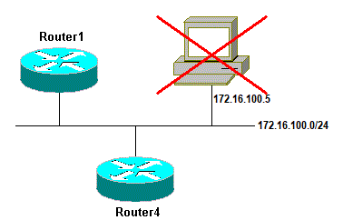
In this scenario, this is the Ethernet connection:
 Address Resolution Protocol Issue
Router4#ping 172.16.100.5

Type escape sequence to abort.
Sending 5, 100-byte ICMP Echos to 172.16.100.5, timeout is 2 seconds:

Jan 20 17:04:05.167: IP: s=172.16.100.4 (local), d=172.16.100.5 (Ethernet0), len 100,
  sending
Jan 20 17:04:05.171: IP: s=172.16.100.4 (local), d=172.16.100.5 (Ethernet0), len 100,
  encapsulation failed.
Jan 20 17:04:07.167: IP: s=172.16.100.4 (local), d=172.16.100.5 (Ethernet0), len 100,
  sending
Jan 20 17:04:07.171: IP: s=172.16.100.4 (local), d=172.16.100.5 (Ethernet0), len 100,
  encapsulation failed.
Jan 20 17:04:09.175: IP: s=172.16.100.4 (local), d=172.16.100.5 (Ethernet0), len 100,
  sending
Jan 20 17:04:09.183: IP: s=172.16.100.4 (local), d=172.16.100.5 (Ethernet0), len 100,
  encapsulation failed.
Jan 20 17:04:11.175: IP: s=172.16.100.4 (local), d=172.16.100.5 (Ethernet0), len 100,
  sending
Jan 20 17:04:11.179: IP: s=172.16.100.4 (local), d=172.16.100.5 (Ethernet0), len 100,
  encapsulation failed.
Jan 20 17:04:13.175: IP: s=172.16.100.4 (local), d=172.16.100.5 (Ethernet0), len 100,
  sending
Jan 20 17:04:13.179: IP: s=172.16.100.4 (local), d=172.16.100.5 (Ethernet0), len 100,
  encapsulation failed.
Success rate is 0 percent (0/5)
Router4#
In this example, the ping does not work due to «encapsulation failed» message. This means that the router knows on which interface it has to send the packet but does not know how to do it. In this case, you need to understand how the Address Resolution Protocol (ARP) works.
ARP is a protocol used to map the Layer 2 address (MAC address) to a Layer 3 address (IP address). You can check this with the show arp command:
Router4#show arp
Protocol  Address          Age (min)  Hardware Addr   Type   Interface
Internet  172.16.100.4               -   0000.0c5d.7a0d  ARPA   Ethernet0
Internet  172.16.100.7              10   0060.5cf4.a955  ARPA   Ethernet0
Return to the «encapsulation failed» problem, but this time enable the debug arp command:
Router4#debug arp
ARP packet debugging is on

Router4#ping 172.16.100.5

Type escape sequence to abort.
Sending 5, 100-byte ICMP Echos to 172.16.100.5, timeout is 2 seconds:

Jan 20 17:19:43.843: IP ARP: creating incomplete entry for IP address: 172.16.100.5
  interface Ethernet0
Jan 20 17:19:43.847: IP ARP: sent req src 172.16.100.4 0000.0c5d.7a0d,
                 dst 172.16.100.5 0000.0000.0000 Ethernet0.
Jan 20 17:19:45.843: IP ARP: sent req src 172.16.100.4 0000.0c5d.7a0d,
                 dst 172.16.100.5 0000.0000.0000 Ethernet0.
Jan 20 17:19:47.843: IP ARP: sent req src 172.16.100.4 0000.0c5d.7a0d,
                 dst 172.16.100.5 0000.0000.0000 Ethernet0.
Jan 20 17:19:49.843: IP ARP: sent req src 172.16.100.4 0000.0c5d.7a0d,
                 dst 172.16.100.5 0000.0000.0000 Ethernet0.
Jan 20 17:19:51.843: IP ARP: sent req src 172.16.100.4 0000.0c5d.7a0d,
                 dst 172.16.100.5 0000.0000.0000 Ethernet0.
Success rate is 0 percent (0/5)
The previous output shows that Router4 broadcasts packets and sends them to the Ethernet broadcast address FFFF.FFFF.FFFF. Here, the 0000.0000.0000 means that Router4 looks for the MAC address of the destination 172.16.100.5. Since it does not know the MAC address while the ARP is requested in this example, it uses 0000.0000.000 as a placeholder in the broadcast frames sent out of interface Ethernet 0 and asks which MAC address corresponds to 172.16.100.5. If there is no answer, the MAC address that corresponds to the IP address in the show arp output is marked as incomplete:
Router4#show arp
Protocol  Address          Age (min)  Hardware Addr   Type   Interface
Internet  172.16.100.4               -   0000.0c5d.7a0d  ARPA   Ethernet0
Internet  172.16.100.5               0   Incomplete      ARPA
Internet  172.16.100.7               2   0060.5cf4.a955  ARPA   Ethernet0
After a predetermined period, this incomplete entry is purged from the ARP table. As long as the MAC address is not in the ARP table, the ping fails as a result of «encapsulation failed».
Delay
By default, if you do not receive an answer from the remote end within two seconds, the ping fails:
Router1#ping 172.16.0.12

Type escape sequence to abort.
Sending 5, 100-byte ICMP Echos to 172.16.0.12, timeout is 2 seconds:
.....
Success rate is 0 percent (0/5)
On networks with a slow link or a long delay, two seconds are not enough. You can change this default with an extended ping:
Router1#ping
Protocol [ip]:
Target IP address:  172.16.0.12
Repeat count [5]:
Datagram size [100]:
Timeout in seconds [2]: 30
Extended commands [n]:
Sweep range of sizes [n]:

Type escape sequence to abort.
Sending 5, 100-byte ICMP Echos to 172.16.0.12, timeout is 30 seconds:
!!!!!
Success rate is 100 percent (5/5), round-trip min/avg/max = 1458/2390/6066 ms
For more information on the extended ping command, see Understand the Extended Ping and Extended Traceroute Commands .
In the previous example, when the timeout was increased the ping was successful.
Note: The average round-trip time is more than two seconds.
Correct Source Address
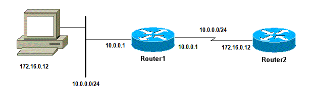
This example is a common scenario:
 Correct Source Address
Add a LAN interface on Router1:
Router1(config)#interface ethernet0
Router1(config-if)#ip address 10.0.0.1 255.255.255.0
From a station on the LAN, you can ping Router1. From Router1 you can ping Router2. But from a station on the LAN, you cannot ping Router2.
From Router1, you can ping Router2 because, by default, you use the IP address of the outgoing interface as the source address in your ICMP packet. Router2 does not have information about this new LAN. If it has to reply to a packet from this network, it does not know how to handle it.
Router1#debug ip packet
IP packet debugging is on
Warning: When the debug ip packet command is used on a production router it can cause high CPU utilization. This can result in a severe performance degradation or a network outage.
Router1#ping 172.16.0.12

Type escape sequence to abort.
Sending 5, 100-byte ICMP Echos to 172.16.0.12, timeout is 2 seconds:
!!!!!
Success rate is 100 percent (5/5), round-trip min/avg/max = 4/7/9 ms
Router1#

Jan 20 16:35:54.227: IP: s=172.16.12.1 (local), d=172.16.0.12 (Serial0), len 100, sending
Jan 20 16:35:54.259: IP: s=172.16.0.12 (Serial0), d=172.16.12.1 (Serial0), len 100, rcvd 3
The previous output example works because the source address of the packet sent is 172.16.12.1. To simulate a packet from the LAN, you need to use an extended ping:
Router1#ping
Protocol [ip]:
Target IP address: 172.16.0.12
Repeat count [5]:
Datagram size [100]:
Timeout in seconds [2]:
Extended commands [n]: y
Source address or interface: 10.0.0.1
Type of service [0]:
Set DF bit in IP header? [no]:
Validate reply data? [no]:
Data pattern [0xABCD]:
Loose, Strict, Record, Timestamp, Verbose[none]:
Sweep range of sizes [n]:
Type escape sequence to abort.
Sending 5, 100-byte ICMP Echos to 172.16.0.12, timeout is 2 seconds:

Jan 20 16:40:18.303: IP: s=10.0.0.1 (local), d=172.16.0.12 (Serial0), len 100,
 sending.
Jan 20 16:40:20.303: IP: s=10.0.0.1 (local), d=172.16.0.12 (Serial0), len 100,
 sending.
Jan 20 16:40:22.303: IP: s=10.0.0.1 (local), d=172.16.0.12 (Serial0), len 100,
 sending.
Jan 20 16:40:24.303: IP: s=10.0.0.1 (local), d=172.16.0.12 (Serial0), len 100,
 sending
Jan 20 16:40:26.303: IP: s=10.0.0.1 (local), d=172.16.0.12 (Serial0), len 100,
 sending.
Success rate is 0 percent (0/5)
This time, the source address is 10.0.0.1, and it does not work. Packets are sent but no response is received. To fix this issue, add a route to 10.0.0.0 in Router2. The basic rule is that the pinged device must also know how to send the reply to the source of the ping.
High Input Queue Drops
When a packet enters the router, the router attempts to forward it at interrupt level. If a match cannot be found in an appropriate cache table, the packet is queued in the input queue of the incoming interface to be processed. Some packets are always processed, but with the appropriate configuration and in stable networks, the rate of processed packets must never congest the input queue. If the input queue is full, the packet is dropped.
Though the interface is up, and you cannot ping the device due to high input queue drops. You can check the input drops with the show interface command.
Router1#show interface Serial0/0/0

Serial0/0/0 is up, line protocol is up

  MTU 1500 bytes, BW 1984 Kbit, DLY 20000 usec,
     reliability 255/255, txload 69/255, rxload 43/255
  Encapsulation HDLC, loopback not set
  Keepalive set (10 sec)
  Last input 00:00:02, output 00:00:00, output hang never
  Last clearing of "show interface" counters 01:28:49
  Input queue: 76/75/5553/0 (size/max/drops/flushes);
     Total output drops: 1760
  Queueing strategy: Class-based queueing
  Output queue: 29/1000/64/1760 (size/max total/threshold/drops)
     Conversations  7/129/256 (active/max active/max total)
     Reserved Conversations 4/4 (allocated/max allocated)
     Available Bandwidth 1289 kilobits/sec


!--- Output supressed
As seen from the output, Input Queue Drop is high. Refer to Troubleshoot Input Queue Drops and Output Queue Drops to troubleshoot Input/Output queue drops.
The Traceroute Command
The traceroute command is used to discover the routes that packets actually take when they travel to their destination. The device (for example, a router or a PC) sends out a sequence of User Datagram Protocol (UDP) datagrams to an invalid port address at the remote host.
Three datagrams are sent, each with a Time-To-Live (TTL) field value set to one. The TTL value of 1 causes the datagram to «timeout» as soon as it hits the first router in the path; this router then responds with an ICMP Time Exceeded Message (TEM) that indicates that the datagram has expired.
Another three UDP messages are now sent, each with the TTL value set to 2, which causes the second router to return ICMP TEMs. This process continues until the packets actually reach the other destination. Since these datagrams try to access an invalid port at the destination host, ICMP Port Unreachable Messages are returned, and indicates an unreachable port; this event signals the Traceroute program that it is finished.
The purpose behind this is to record the source of each ICMP Time Exceeded Message to provide a trace of the path the packet took to reach the destination.
Router1#traceroute 172.16.4.34

Type escape sequence to abort.
Tracing the route to 172.16.4.34

  1 172.16.0.12 4 msec 4 msec 4 msec
  2 10.0.3.23 20 msec 16 msec 16 msec
  3 172.16.4.34 16 msec *  16 msec

Jan 20 16:42:48.611: IP: s=172.16.12.1 (local), d=172.16.4.34 (Serial0), len 28,
 sending
Jan 20 16:42:48.615:     UDP src=39911, dst=33434
Jan 20 16:42:48.635: IP: s=172.16.0.12 (Serial0), d=172.16.12.1 (Serial0), len 56,
 rcvd 3
Jan 20 16:42:48.639:     ICMP type=11, code=0

!--- ICMP Time Exceeded Message from Router2.

Jan 20 16:42:48.643: IP: s=172.16.12.1 (local), d=172.16.4.34 (Serial0), len 28,
 sending
Jan 20 16:42:48.647:     UDP src=34237, dst=33435
Jan 20 16:42:48.667: IP: s=172.16.0.12 (Serial0), d=172.16.12.1 (Serial0), len 56,
 rcvd 3
Jan 20 16:42:48.671:     ICMP type=11, code=0
Jan 20 16:42:48.675: IP: s=172.16.12.1 (local), d=172.16.4.34 (Serial0), len 28,
 sending
Jan 20 16:42:48.679:     UDP src=33420, dst=33436
Jan 20 16:42:48.699: IP: s=172.16.0.12 (Serial0), d=172.16.12.1 (Serial0), len 56,
 rcvd 3
Jan 20 16:42:48.703:     ICMP type=11, code=0
This is the first sequence of packets is sent with a TTL=1. The first router, in this case Router2 (172.16.0.12), drops the packet, and sends back to the source (172.16.12.1) a type=11 ICMP message. This corresponds to the Time Exceeded Message.
Jan 20 16:42:48.707: IP: s=172.16.12.1 (local), d=172.16.4.34 (Serial0), len 28,
 sending
Jan 20 16:42:48.711:     UDP src=35734, dst=33437
Jan 20 16:42:48.743: IP: s=10.0.3.23 (Serial0), d=172.16.12.1 (Serial0), len 56,
 rcvd 3
Jan 20 16:42:48.747:     ICMP type=11, code=0

!--- ICMP Time Exceeded Message from Router3.

Jan 20 16:42:48.751: IP: s=172.16.12.1 (local), d=172.16.4.34 (Serial0), len 28,
 sending
Jan 20 16:42:48.755:     UDP src=36753, dst=33438
Jan 20 16:42:48.787: IP: s=10.0.3.23 (Serial0), d=172.16.12.1 (Serial0), len 56,
 rcvd 3
Jan 20 16:42:48.791:     ICMP type=11, code=0
Jan 20 16:42:48.795: IP: s=172.16.12.1 (local), d=172.16.4.34 (Serial0), len 28,
 sending
Jan 20 16:42:48.799:     UDP src=36561, dst=33439
Jan 20 16:42:48.827: IP: s=10.0.3.23 (Serial0), d=172.16.12.1 (Serial0), len 56,
 rcvd 3
Jan 20 16:42:48.831:     ICMP type=11, code=0
The same process occurs for Router3 (10.0.3.23) with a TTL=2:
Jan 20 16:42:48.839: IP: s=172.16.12.1 (local), d=172.16.4.34 (Serial0), len 28,
 sending
Jan 20 16:42:48.843:     UDP src=34327, dst=33440
Jan 20 16:42:48.887: IP: s=172.16.4.34 (Serial0), d=172.16.12.1 (Serial0), len 56,
 rcvd 3
Jan 20 16:42:48.891:     ICMP type=3, code=3

!--- Port Unreachable message from Router4.

Jan 20 16:42:48.895: IP: s=172.16.12.1 (local), d=172.16.4.34 (Serial0), len 28,
 sending
Jan 20 16:42:48.899:     UDP src=37534, dst=33441
Jan 20 16:42:51.895: IP: s=172.16.12.1 (local), d=172.16.4.34 (Serial0), len 28,
 sending
Jan 20 16:42:51.899:     UDP src=37181, dst=33442
Jan 20 16:42:51.943: IP: s=172.16.4.34 (Serial0), d=172.16.12.1 (Serial0), len 56,
 rcvd 3
Jan 20 16:42:51.947:     ICMP type=3, code=3
With a TTL=3, Router4 is finally reached. This time, since the port is not valid, Router4 sends back to Router1 an ICMP message with type=3, a Destination Unreachable Message, and code=3 meaning port unreachable.
The next table lists the characters that can appear in the traceroute command output.
IP Traceroute Text Characters
| Character | Description |
|---|---|
| nn msec | For each node, the round-trip time in milliseconds for the specified number of probes |
| * | The probe timed out |
| A | Administratively prohibited (example, access-list) |
| Q | Source quench (destination too busy) |
| I | User interrupted test |
| U | Port unreachable |
| H | Host unreachable |
| N | Network unreachable |
| P | Protocol Unreachable |
| T | Timeout |
| ? | Unknown packet type |
Performance
You can obtain the round-trip time (RTT) with the ping and traceroute commands. This is the time required to send an echo packet and get an answer back. This can provide a rough idea of the delay on the link. However, these figures are not precise enough to be used for performance evaluation.
When a packet destination is the router itself, this packet has to be process-switched. The processor has to handle the information from this packet and send an answer back. This is not the main goal of a router. By definition, a router is built to route packets. An answered ping is offered as a best-effort service.
To illustrate this, this is an example of a ping from Router1 to Router2:
Router1#ping 172.16.0.12

Type escape sequence to abort.
Sending 5, 100-byte ICMP Echos to 172.16.0.12, timeout is 2 seconds:
!!!!!
Success rate is 100 percent (5/5), round-trip min/avg/max = 4/4/4 ms
The RTT is approximately four milliseconds. After you enable some process-intensive features on Router2, try to ping Router2 from Router1.
Router1#ping 172.16.0.12

Type escape sequence to abort.
Sending 5, 100-byte ICMP Echos to 172.16.0.12, timeout is 2 seconds:
!!!!!
Success rate is 100 percent (5/5), round-trip min/avg/max = 24/25/28 ms
The RTT has dramatically increased here. Router2 is quite busy, and the priority is not to answer the ping. A better way to test router performance is with traffic that goes through the router.
 Traffic Through the Router
The traffic is then fast-switched and is handled by the router with the highest priority. The basic network illustrates this:
 Basic Network 3 Routers
Ping Router3 from Router1:
Router1#ping 10.0.3.23

Type escape sequence to abort.
Sending 5, 100-byte ICMP Echos to 10.0.3.23, timeout is 2 seconds:
!!!!!
Success rate is 100 percent (5/5), round-trip min/avg/max = 32/32/32 ms
The traffic goes through Router2 and is now fast-switched. Enable the process-intensive feature on Router2:
Router1#ping 10.0.3.23

Type escape sequence to abort.
Sending 5, 100-byte ICMP Echos to 10.0.3.23, timeout is 2 seconds:
!!!!!
Success rate is 100 percent (5/5), round-trip min/avg/max = 32/32/36 ms
There is almost no difference. This is because, on Router2, the packets are now handled at interrupt level.
Use the Debug Command
Before you use debug commands, refer to Important Information on Debug Commands .
The different debug commands used in this article shows what happens when a ping or traceroute command is used. These commands can help you troubleshoot issues. However, in a production environment, debugs must be used with caution. If your CPU is not powerful, or if you have a lot of process-switched packets, they can easily stall your device. There are a couple of ways to minimize the impact of the debug command on the router. One way is to use access lists to narrow down the specific traffic that you want to monitor.
Here is an example:
Router4#debug ip packet ?
  <1-199>      Access list
  <1300-2699>  Access list (expanded range)
  detail       Print more debugging detail

Router4#configure terminal
Router4(config)#access-list 150 permit ip host 172.16.12.1 host 172.16.4.34
Router4(config)#^Z

Router4#debug ip packet 150
IP packet debugging is on for access list 150

Router4#show debug
Generic IP:
  IP packet debugging is on for access list 150

Router4#show access-list
Extended IP access list 150
    permit ip host 172.16.12.1 host 172.16.4.34 (5 matches)
With this configuration, Router4 only prints the debug message that matches the access-list 150. A ping from Router1 causes this message to display:
Router4#
Jan 20 16:51:16.911: IP: s=172.16.12.1 (Serial0), d=172.16.4.34 (Serial0), len 100,
 rcvd 3
Jan 20 16:51:17.003: IP: s=172.16.12.1 (Serial0), d=172.16.4.34 (Serial0), len 100,
 rcvd 3
Jan 20 16:51:17.095: IP: s=172.16.12.1 (Serial0), d=172.16.4.34 (Serial0), len 100,
 rcvd 3
Jan 20 16:51:17.187: IP: s=172.16.12.1 (Serial0), d=172.16.4.34 (Serial0), len 100,
 rcvd 3
Jan 20 16:51:17.279: IP: s=172.16.12.1 (Serial0), d=172.16.4.34 (Serial0), len 100,
 rcvd 3
The answer to the problem does not come from Router4 because these packets do not match the access-list. To see them, add:
Router4(config)#access-list 150 permit ip host 172.16.12.1 host 172.16.4.34
Router4(config)#access-list 150 permit ip host 172.16.4.34 host 172.16.12.1
Results:
Jan 20 16:53:16.527: IP: s=172.16.12.1 (Serial0), d=172.16.4.34 (Serial0), len 100,
 rcvd 3
Jan 20 16:53:16.531: IP: s=172.16.4.34 (local), d=172.16.12.1 (Serial0), len 100,
 sending
Jan 20 16:53:16.627: IP: s=172.16.12.1 (Serial0), d=172.16.4.34 (Serial0), len 100,
 rcvd 3
Jan 20 16:53:16.635: IP: s=172.16.4.34 (local), d=172.16.12.1 (Serial0), len 100,
 sending
Jan 20 16:53:16.727: IP: s=172.16.12.1 (Serial0), d=172.16.4.34 (Serial0), len 100,
 rcvd 3
Jan 20 16:53:16.731: IP: s=172.16.4.34 (local), d=172.16.12.1 (Serial0), len 100,
 sending
Jan 20 16:53:16.823: IP: s=172.16.12.1 (Serial0), d=172.16.4.34 (Serial0), len 100,
 rcvd 3
Jan 20 16:53:16.827: IP: s=172.16.4.34 (local), d=172.16.12.1 (Serial0), len 100,
 sending
Jan 20 16:53:16.919: IP: s=172.16.12.1 (Serial0), d=172.16.4.34 (Serial0), len 100,
 rcvd 3
Jan 20 16:53:16.923: IP: s=172.16.4.34 (local), d=172.16.12.1 (Serial0), len 100,
 sending
Another way to lower the impact of the debug command is to buffer the debug messages and display them with the show log command once the debug has been turned off:
Router4#configure terminal
Router4(config)#no logging console
Router4(config)#logging buffered 5000
Router4(config)#^Z

Router4#debug ip packet
IP packet debugging is on
Router4#ping 172.16.12.1

Type escape sequence to abort.
Sending 5, 100-byte ICMP Echos to 172.16.12.1, timeout is 2 seconds:
!!!!!
Success rate is 100 percent (5/5), round-trip min/avg/max = 36/36/37 ms

Router4#undebug all
All possible debugging has been turned off

Router4#show log
Syslog logging: enabled (0 messages dropped, 0 flushes, 0 overruns)
    Console logging: disabled
    Monitor logging: level debugging, 0 messages logged
    Buffer logging: level debugging, 61 messages logged
    Trap logging: level informational, 59 message lines logged

Log Buffer (5000 bytes):

Jan 20 16:55:46.587: IP: s=172.16.4.34 (local), d=172.16.12.1 (Serial0), len 100,
 sending
Jan 20 16:55:46.679: IP: s=172.16.12.1 (Serial0), d=172.16.4.34 (Serial0), len 100,
 rcvd 3
The ping and traceroute commands are helpful utilities that you can use to troubleshoot network access problems. They are also very easy to use. These two commands are the widely used by network engineers.
Related Information
- Understand the Extended ping and Extended Traceroute Commands
- Technical Support — Cisco Systems
Материал из Xgu.ru
Перейти к: навигация, поиск
| Данная страница находится в разработке. Эта страница ещё не закончена. Информация, представленная здесь, может оказаться неполной или неверной. Если вы считаете, что её стоило бы доработать как можно быстрее, пожалуйста, скажите об этом. |
- Автор: Наташа Самойленко
Эта страница посвящена поиску неисправностей в настройках и работе коммутаторов и маршрутизаторов под управлением IOS.
Страница может пригодиться для подготовки к экзамену TSHOOT.
Страница TSHOOT посвящена экзамену.
На ней описан сам экзамен, возможные сложности, топология, оценка времени, пару советов по сдаче и ссылки на полезные материалы.
На странице Cisco ASA/Troubleshooting описываются механизмы и команды, которые могут использоваться для поиска неисправностей при настройке Cisco ASA.
Содержание
- 1 Управление отображением команд в CLI
- 1.1 Фильтрация вывода команд
- 1.1.1 include
- 1.1.2 exclude
- 1.1.3 begin
- 1.1.4 section
- 1.1.5 Условие «или»
- 1.2 Перенаправление вывода команды
- 1.3 Фильтрация sh ip route
- 1.1 Фильтрация вывода команд
- 2 Управление конфигурацией
- 2.1 Archive
- 3 Проверка доступности хоста или сервиса
- 3.1 ping
- 3.1.1 Расширенный ping
- 3.2 traceroute
- 3.3 layer 2 traceroute
- 3.4 telnet
- 3.1 ping
- 4 Проверка самого устройства
- 4.1 CEF
- 4.2 Проверка аппаратной части
- 5 Анализ, реагирование и отправка событий на внешний сервер
- 5.1 Зеркалирование трафика
- 5.1.1 Удаленное зеркалирование (RSPAN)
- 5.2 NetFlow
- 5.3 SNMP
- 5.3.1 Настройка отправки trap
- 5.4 Embedded Event Manager (EEM)
- 5.1 Зеркалирование трафика
- 6 Протоколы
- 6.1 ARP
- 6.2 First Hop Redundancy Protocol (FHRP)
- 6.2.1 HSRP
- 6.2.2 VRRP
- 6.2.3 GLBP
- 7 Поиск неисправностей в настройках маршрутизации
- 7.1 Общие команды
- 7.1.1 ip route profile
- 7.2 Troubleshooting EIGRP
- 7.3 Troubleshooting OSPF
- 7.3.1 Просмотр информации
- 7.3.2 Команды отладки (debug)
- 7.1 Общие команды
- 8 IP services
- 8.1 NAT
- 8.2 DHCP
- 8.3 NTP
- 9 IP-телефония, видео
- 9.1 QoS
- 9.1.1 AutoQoS
- 9.1.2 AutoQoS Enterprise
- 9.2 Multicast
- 9.1 QoS
- 10 IPv6
- 10.1 RIPng
- 10.2 OSPFv3
- 10.3 Туннели
- 10.3.1 IPv6IP
- 11 VPN
- 11.1 Фильтрация вывода команд debug
- 12 Advanced services
- 12.1 IP SLA
- 13 Утилиты
- 14 Команда test
- 15 Дополнительная информация
[править] Управление отображением команд в CLI
[править] Фильтрация вывода команд
[править] include
Первоначальный вывод (частичный):
dyn1# show processes cpu
CPU utilization for five seconds: 1%/0%; one minute: 2%; five minutes: 3%
 PID Runtime(ms)   Invoked      uSecs   5Sec   1Min   5Min TTY Process
   1           4         3       1333  0.00%  0.00%  0.00%   0 Chunk Manager
   2     1842240    253294       7273  0.16%  0.16%  0.16%   0 Load Meter
   3           0         1          0  0.00%  0.00%  0.00%   0 chkpt message ha
   4     4626336    221474      20888  0.00%  0.50%  0.35%   0 Check heaps
   5         928       276       3362  0.00%  0.00%  0.00%   0 Pool Manager
   6           0         2          0  0.00%  0.00%  0.00%   0 Timers
   7           0         2          0  0.00%  0.00%  0.00%   0 ATM AutoVC Perio
   8           0         2          0  0.00%  0.00%  0.00%   0 ATM VC Auto Crea
   9        5292     21102        250  0.00%  0.00%  0.00%   0 IPC Dynamic Cach
  10           0         1          0  0.00%  0.00%  0.00%   0 IPC Zone Manager
  11       81404   1265509         64  0.00%  0.00%  0.00%   0 IPC Periodic Tim
  12       68528   1265509         54  0.00%  0.00%  0.00%   0 IPC Deferred Por
  13           4         1       4000  0.00%  0.00%  0.00%   0 IPC Seat Manager
  14           0         1          0  0.00%  0.00%  0.00%   0 IPC BackPressure
  15       66740   1265509         52  0.00%  0.00%  0.00%   0 EnvMon
  16           0         1          0  0.00%  0.00%  0.00%   0 OIR Handler
  17           0         1          0  0.00%  0.00%  0.00%   0 Crash writer
  18        1664     28053         59  0.00%  0.00%  0.00%   0 ARP Input
  19           0         2          0  0.00%  0.00%  0.00%   0 ATM Idle Timer
  20           0         2          0  0.00%  0.00%  0.00%   0 AAA high-capacit
  21           0         1          0  0.00%  0.00%  0.00%   0 AAA_SERVER_DEADT
Отобразить только те строки, в которых встречается слово BGP:
dyn1# show processes cpu | include BGP
 175      119076   2804506         42  0.00%  0.00%  0.00%   0 BGP Router
 176      140408    163366        859  0.00%  0.00%  0.00%   0 BGP I/O
 177     2982572     90228      33055  0.00%  0.55%  0.31%   0 BGP Scanner
[править] exclude
Первоначальный вывод:
dyn1# sh ip int br
Interface                  IP-Address      OK? Method Status                Protocol
FastEthernet0/0            192.168.20.1    YES NVRAM  up                    up
FastEthernet1/0            192.168.1.1     YES NVRAM  up                    up
FastEthernet2/0            192.168.13.1    YES NVRAM  up                    up
Loopback0                  197.1.1.1       YES NVRAM  up                    up
Loopback1                  197.1.8.1       YES NVRAM  up                    up
Loopback3                  199.1.1.1       YES manual up                    up
Исключить из вывода строки со словом Loopback:
dyn1# sh ip int br | exclude Loopback
Interface                  IP-Address      OK? Method Status                Protocol
FastEthernet0/0            192.168.20.1    YES NVRAM  up                    up
FastEthernet1/0            192.168.1.1     YES NVRAM  up                    up
FastEthernet2/0            192.168.13.1    YES NVRAM  up                    up
Аналогично можно отфильтровать, например, интерфейсы на которых не назначены IP-адреса:
dyn1# sh ip int br | exclude unassigned
[править] begin
Вывести конфигурацию начиная со слова router:
dyn1# sh run | begin router
router ospf 1
 log-adjacency-changes
 network 192.168.0.0 0.0.255.255 area 0
 network 199.0.0.0 0.255.255.255 area 0
!
router bgp 100
 no synchronization
 bgp log-neighbor-changes
 bgp bestpath med missing-as-worst
 network 192.168.1.0
 network 192.168.13.0
 network 197.1.0.0 mask 255.255.0.0
 network 199.1.1.0
 aggregate-address 192.168.1.0 255.255.255.0 summary-only
 neighbor 192.168.20.8 remote-as 8
 neighbor 192.168.20.8 soft-reconfiguration inbound
 neighbor 192.168.20.8 prefix-list private in
 neighbor 192.168.20.9 remote-as 9
 neighbor 192.168.20.9 soft-reconfiguration inbound
 neighbor 192.168.20.9 prefix-list private in
 neighbor 199.2.2.2 remote-as 100
 neighbor 199.2.2.2 update-source Loopback3
 neighbor 199.3.3.3 remote-as 100
 neighbor 199.3.3.3 update-source Loopback3
 neighbor 199.4.4.4 remote-as 100
 neighbor 199.4.4.4 update-source Loopback3
 no auto-summary
!
[править] section
Отобразить раздел конфигурационного файла:
dyn1#sh run | section router ospf
router ospf 1
 log-adjacency-changes
 network 192.168.0.0 0.0.255.255 area 0
 network 199.0.0.0 0.255.255.255 area 0
[править] Условие «или»
Отобразить строки в которых встречаются слова «Administrative Mode» или «Gi»:
dyn# sh interface switchport | i Administrative Mode|Gi
[править] Перенаправление вывода команды
Перенаправление вывода команды на TFTP-сервер без отображения её вывода в консоли:
dyn# show tech-support | redirect tftp://192.168.1.100/tech-support.txt
Перенаправление вывода команды на TFTP-сервер и вывод команды в консоли:
dyn# show tech-support | tee tftp://192.168.1.100/tech.txt
Добавление вывода команды к уже существующему файлу:
dyn# show ip route | append tftp://192.168.1.100/basic.txt
[править] Фильтрация sh ip route
Просмотр маршрутов полученных по OSPF:
dyn1# sh ip route ospf
     199.3.3.0/24 is variably subnetted, 2 subnets, 2 masks
O       199.3.3.3/32 [110/3] via 192.168.1.2, 1w5d, FastEthernet1/0
O    192.168.21.0/24 [110/4] via 192.168.1.2, 1w5d, FastEthernet1/0
     199.2.2.0/24 is variably subnetted, 2 subnets, 2 masks
O       199.2.2.2/32 [110/2] via 192.168.1.2, 1w5d, FastEthernet1/0
O    192.168.7.0/24 [110/4] via 192.168.1.2, 1w5d, FastEthernet1/0
     192.168.1.0/24 is variably subnetted, 4 subnets, 2 masks
O       192.168.1.8/30 [110/3] via 192.168.1.2, 1w5d, FastEthernet1/0
O       192.168.1.4/30 [110/2] via 192.168.1.2, 1w5d, FastEthernet1/0
     199.4.4.0/24 is variably subnetted, 2 subnets, 2 masks
O       199.4.4.4/32 [110/4] via 192.168.1.2, 1w5d, FastEthernet1/0
Посмотреть присутствует ли сеть в таблице маршрутизации (если маршрут существует):
dyn1# sh ip route 192.168.10.0
Routing entry for 192.168.10.0/24
  Known via "bgp 100", distance 200, metric 0
  Tag 8, type internal
  Last update from 192.168.7.8 1w5d ago
  Routing Descriptor Blocks:
  * 192.168.7.8, from 199.4.4.4, 1w5d ago
      Route metric is 0, traffic share count is 1
      AS Hops 2
      Route tag 8
Посмотреть присутствует ли сеть в таблице маршрутизации (если маршрута в таблице нет):
dyn1# sh ip route 192.168.2.0
% Network not in table
Просмотр маршрутов, которые начинаются на указанный префикс (в примере 192.168.0.0/16):
dyn1# sh ip route 192.168.0.0 255.255.0.0 longer-prefixes
Codes: C - connected, S - static, R - RIP, M - mobile, B - BGP
       D - EIGRP, EX - EIGRP external, O - OSPF, IA - OSPF inter area
       N1 - OSPF NSSA external type 1, N2 - OSPF NSSA external type 2
       E1 - OSPF external type 1, E2 - OSPF external type 2
       i - IS-IS, su - IS-IS summary, L1 - IS-IS level-1, L2 - IS-IS level-2
       ia - IS-IS inter area, * - candidate default, U - per-user static route
       o - ODR, P - periodic downloaded static route

Gateway of last resort is not set

C    192.168.13.0/24 is directly connected, FastEthernet2/0
B    192.168.14.0/24 [200/0] via 192.168.7.8, 1w5d
B    192.168.15.0/24 [200/0] via 192.168.7.8, 1w5d
B    192.168.8.0/24 [200/0] via 192.168.7.8, 1w5d
B    192.168.9.0/24 [200/0] via 192.168.7.8, 1w5d
B    192.168.111.0/24 [200/0] via 192.168.7.8, 1w5d
B    192.168.10.0/24 [200/0] via 192.168.7.8, 1w5d
B    192.168.11.0/24 [200/0] via 192.168.7.8, 1w5d
O    192.168.21.0/24 [110/4] via 192.168.1.2, 1w5d, FastEthernet1/0
C    192.168.20.0/24 is directly connected, FastEthernet0/0
B    192.168.6.0/24 [200/0] via 192.168.7.8, 1w5d
B    192.168.112.0/24 [200/0] via 192.168.7.8, 1w5d
O    192.168.7.0/24 [110/4] via 192.168.1.2, 1w5d, FastEthernet1/0
     192.168.1.0/24 is variably subnetted, 4 subnets, 2 masks
O       192.168.1.8/30 [110/3] via 192.168.1.2, 1w5d, FastEthernet1/0
C       192.168.1.0/30 is directly connected, FastEthernet1/0
S       192.168.1.0/24 is directly connected, Null0
O       192.168.1.4/30 [110/2] via 192.168.1.2, 1w5d, FastEthernet1/0
Суммарная информация о таблице маршрутизации:
dyn1# sh ip route summary
IP routing table name is Default-IP-Routing-Table(0)
IP routing table maximum-paths is 16
Route Source    Networks    Subnets     Overhead    Memory (bytes)
connected       5           1           432         816
static          1           1           144         272
ospf 1          2           5           504         952
  Intra-area: 7 Inter-area: 0 External-1: 0 External-2: 0
  NSSA External-1: 0 NSSA External-2: 0
bgp 100         9           3           864         1632
  External: 0 Internal: 12 Local: 0
internal        4                                   4624
Total           21          10          1944        8296
[править] Управление конфигурацией
Замена текущей конфигурации указанным файлом (происходит именно замена, а не совмещение файлов):
router# configure replace ftp://192.168.1.1/dyn1_bgp
[править] Archive
[1]
[править] Проверка доступности хоста или сервиса
[править] ping
Параметры команды ping:
- data — specify data pattern
- df-bit — установить в IP-пакете бит do not fragment
- repeat — указать количество повторов
- size — указать размер пакета
- source — указать адрес или имя отправителя
- timeout — значение интервала таймаут
- validate — validate reply data
Пример использования:
dyn1# ping 192.168.1.10 repeat 7 source 197.1.1.1 timeout 5 size 1500

Type escape sequence to abort.
Sending 7, 1500-byte ICMP Echos to 192.168.1.10, timeout is 5 seconds:
Packet sent with a source address of 197.1.1.1
!!!!!!!
Success rate is 100 percent (7/7), round-trip min/avg/max = 600/759/900 ms
Символы в выводе результатов ping и их значения:
| Символ | Описание |
|---|---|
| ! | Каждый восклицательный знак означает получение ответа |
| . | Таймаут в ожидании ответа |
| U | Получатель недоступен |
| C | A congestion experienced packet was received. |
| I | User interrupted test. |
| M | A destination unreachable error protocol data unit (PDU) was received (Type 3) MTU required but DF bit set (code 4) with the «Next-Hop MTU» set to a non-zero value. If the «Next-hop MTU» is zero then `U’ is printed. |
| ? | Неизвестный тип пакета |
| & | Время жизни пакета истекло |
[править] Расширенный ping
dyn1# ping
Protocol [ip]:
Target IP address: 192.168.1.10
Repeat count [5]: 1
Datagram size [100]:
Timeout in seconds [2]:
Extended commands [n]: y
Source address or interface:
Type of service [0]:
Set DF bit in IP header? [no]: yes
Validate reply data? [no]:
Data pattern [0xABCD]:
Loose, Strict, Record, Timestamp, Verbose[none]:
Sweep range of sizes [n]: y
Sweep min size [36]: 1450
Sweep max size [18024]: 1550
Sweep interval [1]:
Type escape sequence to abort.
Sending 101, [1450..1550]-byte ICMP Echos to 192.168.1.10, timeout is 2 seconds:
Packet sent with the DF bit set
!!!!!!!!!!!!!!!!!!!!!!!!!!!!!!!!!!!!!!!!!!!!!!!!!!!...................
...............................
Success rate is 50 percent (51/101), round-trip min/avg/max = 12/572/1148 ms
[править] traceroute
Символы в выводе результатов traceroute и их значения:
| Символ | Описание |
|---|---|
| * | Истек таймаут ожидания ответа |
| A | Пакет административно запрещен (например, настроен ACL) |
| H | Получатель недоступен |
[править] layer 2 traceroute
[править] telnet
Команда ping используется для проверки работы 3 уровня.
Для проверки 4 уровня, можно использовать команду telnet.
Для этого, после указания IP-адреса, необходимо указать номер порта сервиса, который проверяется.
Например, проверить включен ли HTTP-сервер на хосте 192.168.1.10 (результат Open говорит о том, что сервис запущен):
dyn1# telnet 192.168.1.10 80
Trying 192.168.1.10, 80 ... Open

^C
HTTP/1.1 400 Bad Request
Date: Wed, 17 Mar 2010 08:40:35 GMT
Server: cisco-IOS
Accept-Ranges: none

400 Bad Request

[Connection to 192.168.1.10 closed by foreign host]
Аналогично, если сервис не запущен:
dyn1# telnet 192.168.1.6 80
Trying 192.168.1.6, 80 ...
% Connection refused by remote host
[править] Проверка самого устройства
[править] CEF
- Основная страница: CEF
[править] Проверка аппаратной части
show processes cpu
show memory
show interfaces
show controllers
[править] Анализ, реагирование и отправка событий на внешний сервер
[править] Зеркалирование трафика
Настройка источника трафика:
sw1(config)# monitor session 1 source interface fastethernet 0/10 both
Настройка получателя трафика (порт, к которому подключен анализатор трафика):
sw1(config)# monitor session 1 destination interface fastethernet 0/1
[править] Удаленное зеркалирование (RSPAN)
Настройка удаленного зеркалирования на коммутаторе с которого отправляется трафик:
sw1(config)# monitor session 1 source interface fa 0/10
sw1(config)# monitor session 1 destination remote vlan 100 reflector-port fa 0/1
Настройка удаленного зеркалирования на коммутаторе который получает трафик:
sw1(config)# monitor session 1 source remote vlan 100
sw1(config)# monitor session 1 destination interface fa 0/8
show monitor
[править] NetFlow
Пример настройки NetFlow:
interface FastEthernet0/0
 ip address 192.168.20.1 255.255.255.0
 ip flow ingress
!
interface FastEthernet1/0
 ip address 192.168.1.1 255.255.255.252
 ip flow ingress
!
ip flow-export source Loopback0
ip flow-export version 5
ip flow-export destination 192.168.1.10 5000
Просмотр информации:
dyn1# sh ip cache flow
IP packet size distribution (48 total packets):
   1-32   64   96  128  160  192  224  256  288  320  352  384  416  448  480
   .000 .895 .000 .104 .000 .000 .000 .000 .000 .000 .000 .000 .000 .000 .000

    512  544  576 1024 1536 2048 2560 3072 3584 4096 4608
   .000 .000 .000 .000 .000 .000 .000 .000 .000 .000 .000

IP Flow Switching Cache, 4456704 bytes
  2 active, 65534 inactive, 28 added
  479 ager polls, 0 flow alloc failures
  Active flows timeout in 30 minutes
  Inactive flows timeout in 15 seconds
IP Sub Flow Cache, 402056 bytes
  2 active, 16382 inactive, 22 added, 22 added to flow
  0 alloc failures, 0 force free
  1 chunk, 1 chunk added
  last clearing of statistics never
Protocol         Total    Flows   Packets Bytes  Packets Active(Sec) Idle(Sec)
--------         Flows     /Sec     /Flow  /Pkt     /Sec     /Flow     /Flow
TCP-BGP             17      0.0         1    51      0.0       0.6      15.6
ICMP                 9      0.0         1    70      0.0       3.5      15.7
Total:              26      0.0         1    57      0.0       1.6      15.7

SrcIf         SrcIPaddress    DstIf         DstIPaddress    Pr SrcP DstP  Pkts
Fa1/0         199.4.4.4       Local         199.1.1.1       06 6120 00B3     2
Fa1/0         192.168.1.10    Local         197.1.1.1       01 0000 0303     1
Очистить статистику:
dyn1# clear ip flow stats
[править] SNMP
[править] Настройка отправки trap
Настройка сервера (NMS):
snmp-server host 192.168.1.10 version 2c xguru
Включить отправку всех traps:
snmp-server enable traps
Включить отправку traps для определенных протоколов (например для BGP и OSPF):
snmp-server enable traps bgp
snmp-server enable traps ospf
Включение traps для OSPF включает несколько их подвидов, поэтому конфигурация выглядит так:
dyn1# sh run | inc traps ospf
snmp-server enable traps ospf state-change
snmp-server enable traps ospf errors
snmp-server enable traps ospf retransmit
snmp-server enable traps ospf lsa
snmp-server enable traps ospf cisco-specific state-change nssa-trans-change
snmp-server enable traps ospf cisco-specific state-change shamlink interface-old
snmp-server enable traps ospf cisco-specific state-change shamlink neighbor
snmp-server enable traps ospf cisco-specific errors
snmp-server enable traps ospf cisco-specific retransmit
snmp-server enable traps ospf cisco-specific lsa
[править] Embedded Event Manager (EEM)
- Основная страница: Embedded Event Manager
[править] Протоколы
[править] ARP
Просмотр ARP-кеша:
dyn1# sh ip arp
Protocol  Address          Age (min)  Hardware Addr   Type   Interface
Internet  192.168.13.1            -   0016.3e01.0039  ARPA   FastEthernet2/0
Internet  192.168.1.1             -   0016.3e01.001d  ARPA   FastEthernet1/0
Internet  192.168.1.2             1   0016.3e01.0101  ARPA   FastEthernet1/0
Internet  192.168.20.8            1   0016.3e01.07c1  ARPA   FastEthernet0/0
Internet  192.168.20.9            1   0016.3e01.08c1  ARPA   FastEthernet0/0
Internet  192.168.20.1            -   0016.3e01.0001  ARPA   FastEthernet0/0
Очистка ARP-кеша:
dyn1# clear arp-cache
[править] First Hop Redundancy Protocol (FHRP)
Более подробное описание протоколов на соответствующих страницах.
Тут собрана общая информация о протоколах, которая может помочь при поиске неисправностей.
Некоторые характеристики для сравнения протоколов (тут или тут можно посмотреть похожий вариант сравнения)
| Характеристика протокола | HSRP (2 версия) | VRRP | GLBP |
|---|---|---|---|
| Проприетарный протокол Cisco? | Да | Нет | Да |
| IP-адрес интерфейса может использоваться как виртуальный IP-адрес? | Нет | Да | Нет |
| Несколько маршрутизаторов в группе могут передавать трафик одновременно? | Нет | Нет | Да |
| Режим preempt по умолчанию включен? | Нет | Да | Нет |
| Название ролей маршрутизаторов | Один Active, один Standby, один или более Listening | Один Master, один или более Backup | Один Active Virtual Gateway (AVG), до четырех Active Virtual Forwarder (AVF) |
| Multicast IP-адрес | 224.0.0.102 | 224.0.0.18 | 224.0.0.102 |
| Виртуальный MAC-адрес | 0000:0C9F:Fxxx
(xxx — номер группы) |
0000:5E00:01xx
(xx — номер группы) |
0007.b400.yyxx
(yy — номер группы, xx — номер маршрутизатора в группе) |
| Hello интервал по умолчанию | 3 секунды | 1 секунда | 3 секунды |
| Holdtime по умолчанию | 10 секунд | 3 + (256 — Priority)/256 | 10 секунд |
| Приоритет интерфейса по умолчанию | 100 | 100 | 100 |
| Сообщения протокола | Hello, Coup, Resign | Advertisement | Hello … |
В каждом разделе приведен пример базовых настроек протоколов.
[править] HSRP
Understanding and Troubleshooting HSRP Problems in Catalyst Switch Networks
[править] VRRP
[править] GLBP
[править] Поиск неисправностей в настройках маршрутизации
[править] Общие команды
События таблицы маршрутизации:
debug ip routing
[править] ip route profile
dyn2(config)# ip route profile
dyn2#sh ip route profile
IP routing table change statistics:
Frequency of changes in a 5 second sampling interval
-------------------------------------------------------------
Change/   Fwd-path  Prefix   Nexthop  Pathcount  Prefix
interval  change    add      change   change     refresh
-------------------------------------------------------------
0         1         1        1        1          1
1         0         0        0        0          0
2         0         0        0        0          0
3         0         0        0        0          0
4         0         0        0        0          0
5         0         0        0        0          0
10        0         0        0        0          0
15        0         0        0        0          0
20        0         0        0        0          0
25        0         0        0        0          0
30        0         0        0        0          0
55        0         0        0        0          0
80        0         0        0        0          0
105       0         0        0        0          0
130       0         0        0        0          0
155       0         0        0        0          0
280       0         0        0        0          0
405       0         0        0        0          0
[править] Troubleshooting EIGRP
show ip eigrp interfaces
show ip eigrp neighbors
show ip eigrp topology
Вывод всех пакетов EIGRP, которыми маршрутизатор обменивается с соседями:
debug eigrp packets
Вывод информации, которая содержится в пакетах EIGRP и как маршрутизатор их обрабатывает:
debug ip eigrp
[править] Troubleshooting OSPF
[править] Просмотр информации
Отображение всех интерфейсов, которые настроены для работы по OSPF
dyn2#sh ip ospf interface
Loopback3 is up, line protocol is up
  Internet Address 199.2.2.2/24, Area 0
  Process ID 1, Router ID 199.2.2.2, Network Type LOOPBACK, Cost: 1
  Loopback interface is treated as a stub Host
FastEthernet1/0 is up, line protocol is up
  Internet Address 192.168.1.5/30, Area 0
  Process ID 1, Router ID 199.2.2.2, Network Type BROADCAST, Cost: 1
  Transmit Delay is 1 sec, State BDR, Priority 1
  Designated Router (ID) 199.3.3.3, Interface address 192.168.1.6
  Backup Designated router (ID) 199.2.2.2, Interface address 192.168.1.5
  Timer intervals configured, Hello 10, Dead 40, Wait 40, Retransmit 5
    oob-resync timeout 40
    Hello due in 00:00:00
  Supports Link-local Signaling (LLS)
  Index 2/2, flood queue length 0
  Next 0x0(0)/0x0(0)
  Last flood scan length is 1, maximum is 2
  Last flood scan time is 0 msec, maximum is 4 msec
  Neighbor Count is 1, Adjacent neighbor count is 1
    Adjacent with neighbor 199.3.3.3  (Designated Router)
  Suppress hello for 0 neighbor(s)
FastEthernet0/0 is up, line protocol is up
  Internet Address 192.168.1.2/30, Area 0
  Process ID 1, Router ID 199.2.2.2, Network Type BROADCAST, Cost: 1
  Transmit Delay is 1 sec, State BDR, Priority 1
  Designated Router (ID) 199.1.1.1, Interface address 192.168.1.1
  Backup Designated router (ID) 199.2.2.2, Interface address 192.168.1.2
  Timer intervals configured, Hello 10, Dead 40, Wait 40, Retransmit 5
    oob-resync timeout 40
    Hello due in 00:00:09
  Supports Link-local Signaling (LLS)
  Index 1/1, flood queue length 0
  Next 0x0(0)/0x0(0)
  Last flood scan length is 1, maximum is 3
  Last flood scan time is 0 msec, maximum is 4 msec
  Neighbor Count is 1, Adjacent neighbor count is 1
    Adjacent with neighbor 199.1.1.1  (Designated Router)
  Suppress hello for 0 neighbor(s)
Параметр brief в sh ip ospf interface позволяет вывести информацию в более сжатом виде:
dyn2# sh ip ospf interface brief
Interface    PID   Area            IP Address/Mask    Cost  State Nbrs F/C
Lo3          1     0               199.2.2.2/24       1     LOOP  0/0
Fa1/0        1     0               192.168.1.5/30     1     BDR   1/1
Fa0/0        1     0               192.168.1.2/30     1     BDR   1/1
Соседи и состояние отношений соседства:
Neighbor ID     Pri   State           Dead Time   Address         Interface
199.3.3.3         1   FULL/DR         00:00:31    192.168.1.6     FastEthernet1/0
199.1.1.1         1   FULL/DR         00:00:39    192.168.1.1     FastEthernet0/0
Информация о том как часто маршрутизатор запускал алгоритм SPF:
dyn2# sh ip ospf statistics

OSPF process ID 1
------------------------------------------

  Area 0: SPF algorithm executed 7 times

  Summary OSPF SPF statistic

  SPF calculation time
Delta T   Intra D-Intra Summ    D-Summ  Ext     D-Ext   Total   Reason
2w2d   8        0       0       0       0       0       8       R, N, X
2w2d   8        0       0       0       0       0       8       R,
2w1d   4        4       0       0       0       0       8       R, N,
2w1d   0        0       0       0       0       0       0       R,
2w1d   4        0       0       0       0       0       4       R, N,
2w1d   4        0       0       0       0       0       4       R, N,
2w1d   8        0       0       0       0       0       8       R, N,
1d15h   8       0       0       0       0       0       16      R, N, SN, SA, X
1d15h   0       0       0       0       0       0       0       R, N, SN, SA, X
1d15h   0       0       0       0       0       0       0       R, N, SN, SA, X
Просмотр информации о virtual link:
show ip ospf virtual-links
[править] Команды отладки (debug)
В реальном времени вывести информацию о том когда выполняется алгоритм SPF (предварительно интерфейс соседа был отключен, а на время выполнения команды debug интерфейс был включен):
dyn2# debug ip ospf monitor
*Mar 19 08:08:03.464: OSPF: reset throttling to 0ms
*Mar 19 08:08:04.620: %OSPF-5-ADJCHG: Process 1, Nbr 199.3.3.3 on FastEthernet1/0 from LOADING to FULL, Loading Done
dyn2#
*Mar 19 08:08:04.620: OSPF: Schedule SPF in area 0
      Change in LS ID 199.3.3.3, LSA type R, , spf-type Full
*Mar 19 08:08:04.624: OSPF: Schedule SPF in area 0
      Change in LS ID 192.168.1.6, LSA type N, , spf-type Full
*Mar 19 08:08:04.628: OSPF: reset throttling to 5000ms
*Mar 19 08:08:04.628: OSPF: schedule SPF: spf_time 2w2d wait_interval 5000ms
*Mar 19 08:08:05.120: OSPF: reset throttling to 0ms
*Mar 19 08:08:05.120: OSPF: wait_interval 5000ms next wait_interval 5000ms
*Mar 19 08:08:05.124: OSPF: Schedule SPF in area 0
      Change in LS ID 199.2.2.2, LSA type R, , spf-type Full
*Mar 19 08:08:05.124: OSPF: reset throttling to 0ms
dyn2#
*Mar 19 08:08:05.124: OSPF: Schedule SPF in area 0
      Change in LS ID 199.2.2.2, LSA type N, , spf-type Full
dyn2#
*Mar 19 08:08:09.628: OSPF: Begin SPF at 1444907.028ms, process time 13200ms
*Mar 19 08:08:09.628:       spf_time 2w2d, wait_interval 5000ms
*Mar 19 08:08:09.636: OSPF: wait_interval 10000ms next wait_interval 10000ms
*Mar 19 08:08:09.636: OSPF: End SPF at 1444907.036ms, Total elapsed time 8ms
*Mar 19 08:08:09.636:       Schedule time 2w2d, Next wait_interval 10000ms
*Mar 19 08:08:09.636:       Intra: 0ms, Inter: 0ms, External: 0ms
*Mar 19 08:08:09.636:       R: 2, N: 2, Stubs: 4
*Mar 19 08:08:09.640:       SN: 0, SA: 0, X5: 0, X7: 0
*Mar 19 08:08:09.640:       SPF suspends: 0 intra, 0 total

dyn2#
*Mar 19 08:08:10.104: OSPF: Schedule SPF in area 0
      Change in LS ID 199.3.3.3, LSA type R, , spf-type Full
dyn2#
*Mar 19 08:08:19.636: OSPF: Begin SPF at 1444917.036ms, process time 13220ms
*Mar 19 08:08:19.636:       spf_time 2w2d, wait_interval 10000ms
*Mar 19 08:08:19.648: OSPF: wait_interval 10000ms next wait_interval 10000ms
*Mar 19 08:08:19.648: OSPF: End SPF at 1444917.048ms, Total elapsed time 12ms
*Mar 19 08:08:19.648:       Schedule time 2w2d, Next wait_interval 10000ms
*Mar 19 08:08:19.648:       Intra: 12ms, Inter: 0ms, External: 0ms
*Mar 19 08:08:19.652:       R: 4, N: 3, Stubs: 8
*Mar 19 08:08:19.652:       SN: 0, SA: 0, X5: 0, X7: 0
*Mar 19 08:08:19.652:       SPF suspends: 0 intra, 0 total
Отображение пакетов OSPF в реальном времени:
dyn2# debug ip ospf packet
OSPF packet debugging is on
dyn2#
*Mar 19 08:10:43.360: OSPF: rcv. v:2 t:1 l:48 rid:199.3.3.3
      aid:0.0.0.0 chk:D536 aut:0 auk: from FastEthernet1/0
dyn2#
*Mar 19 08:10:46.960: OSPF: rcv. v:2 t:1 l:48 rid:199.1.1.1
      aid:0.0.0.0 chk:D742 aut:0 auk: from FastEthernet0/0
dyn2#
*Mar 19 08:10:53.172: OSPF: rcv. v:2 t:1 l:48 rid:199.3.3.3
      aid:0.0.0.0 chk:D536 aut:0 auk: from FastEthernet1/0
Отображение информации об установке отношений соседства (и выбора DR и BDR):
dyn2# debug ip ospf adj
dyn2#
*Mar 19 08:14:04.120: OSPF: Rcv DBD from 199.3.3.3 on FastEthernet1/0 seq 0x10D9 opt 0x52 flag 0x7 len 32  mtu 1500
state INIT
*Mar 19 08:14:04.120: OSPF: 2 Way Communication to 199.3.3.3 on FastEthernet1/0,
state 2WAY
*Mar 19 08:14:04.120: OSPF: Neighbor change Event on interface FastEthernet1/0
*Mar 19 08:14:04.120: OSPF: DR/BDR election on FastEthernet1/0
*Mar 19 08:14:04.120: OSPF: Elect BDR 199.3.3.3
*Mar 19 08:14:04.120: OSPF: Elect DR 199.2.2.2
*Mar 19 08:14:04.120:        DR: 199.2.2.2 (Id)   BDR: 199.3.3.3 (Id)
*Mar 19 08:14:04.120: OSPF: Send DBD to 199.3.3.3 on FastEthernet1/0 seq 0xD6B opt 0x52 flag 0x7 len 32
*Mar 19 08:14:04.120: OSPF: NBR Negotiation Done. We are the SLAVE
*Mar 19 08:14:04.124: OSPF: Send DBD to 199.3.3.3 on FastEthernet1/0 seq 0x10D9 opt 0x52  flag 0x2 len 152
*Mar 19 08:14:04.132: OSPF: Rcv DBD from 199.3.3.3 on FastEthernet1/0 seq 0x10DA opt 0x52  flag 0x3 len 172  mtu 1500
state EXCHANGE
*Mar 19 08:14:04.132: OSPF: Send DBD to 199.3.3.3
dyn2#on FastEthernet1/0 seq 0x10DA opt 0x52 flag 0x0 len 32
*Mar 19 08:14:04.132: OSPF: Database request to 199.3.3.3
*Mar 19 08:14:04.132: OSPF: sent LS REQ packet to 192.168.1.6, length 24
*Mar 19 08:14:04.140: OSPF: Rcv DBD from 199.3.3.3 on FastEthernet1/0 seq 0x10DB opt 0x52 flag 0x1 len 32  mtu 1500
state EXCHANGE
*Mar 19 08:14:04.140: OSPF: Exchange Done with 199.3.3.3 on FastEthernet1/0
*Mar 19 08:14:04.140: OSPF: Send DBD to 199.3.3.3 on FastEthernet1/0 seq 0x10DB opt 0x52 flag 0x0 len 32
*Mar 19 08:14:04.144: OSPF: No full nbrs to build Net Lsa for interface FastEthernet1/0
*Mar 19 08:14:04.144: OSPF: Build network LSA for FastEthernet1/0, router ID 199.2.2.2
*Mar 19 08:14:04.144: OSPF: Build network LSA for FastEthernet1/0, router ID 199.2.2.2
*Mar 19 08:14:04.144: OSPF: Synchronized with 199.3.3.3 on FastEthernet1/0,
state FULL
*Mar 19 08:14:04.148: %OSPF-5-ADJCHG: Process 1, Nbr 199.3.3.3 on FastEthernet1/0 from LOADING to FULL, Loading Done
dyn2#
*Mar 19 08:14:04.664: OSPF: Build router LSA for area 0, router ID 199.2.2.2, seq 0x8000028C
dyn2#
*Mar 19 08:14:07.952: OSPF: Neighbor change Event on interface FastEthernet1/0
*Mar 19 08:14:07.952: OSPF: DR/BDR election on FastEthernet1/0
*Mar 19 08:14:07.952: OSPF: Elect BDR 199.3.3.3
*Mar 19 08:14:07.956: OSPF: Elect DR 199.2.2.2
*Mar 19 08:14:07.956:        DR: 199.2.2.2 (Id)   BDR: 199.3.3.3 (Id)
*Mar 19 08:14:07.956: OSPF: Neighbor change Event on interface FastEthernet1/0
*Mar 19 08:14:07.956: OSPF: DR/BDR election on FastEthernet1/0
*Mar 19 08:14:07.956: OSPF: Elect BDR 199.3.3.3
*Mar 19 08:14:07.960: OSPF: Elect DR 199.2.2.2
*Mar 19 08:14:07.960:        DR: 199.2.2.2 (Id)   BDR: 199.3.3.3 (Id)
dyn2#
*Mar 19 08:14:09.144: OSPF: Build network LSA for FastEthernet1/0, router ID 199.2.2.2
*Mar 19 08:14:09.144: OSPF: Build network LSA for FastEthernet1/0, router ID 199.2.2.2
dyn2# debug ip ospf events
[править] IP services
[править] NAT
router# sh ip nat translations
router# sh ip nat statistics
router# debug ip nat
[править] DHCP
router# show ip dhcp binding
router# show ip dhcp conflict
router# show ip dhcp server statistics
router# clear ip dhcp binding [ip-address]
[править] NTP
[править] IP-телефония, видео
[править] QoS
[править] AutoQoS
router(config-if)# auto qos voip [trust]
router# show auto qos voip [interface <id>]
switch(config-if)# auto qos voip cisco-phone
[править] AutoQoS Enterprise
Запустить процесс обнаружения:
router(config-if)# auto discovery qos [trust]
Посмотреть предложенные настройки:
router# show auto discovery qos
Применить настройки:
router(config-if)# auto qos
[править] Multicast
[править] IPv6
Включение маршрутизации IPv6 трафика:
ipv6 unicast-routing
[править] RIPng
ipv6 router rip testRIPng

interface fa0/0
 ipv6 rip testRIPng enable
[править] OSPFv3
ipv6 router ospf 1
 router-id 192.168.1.1

interface fa0/0
 ipv6 ospf 1 area 0
[править] Туннели
[править] IPv6IP
interface Tunnel 0
 ipv6 address ...
 tunnel source 192.168.1.1
 tunnel destination 192.168.3.1
 tunnel mode ipv6ip
[править] VPN
- ISAKMP/IKE Phase 1 Connections
[править] Фильтрация вывода команд debug
- [2]
В ситуации когда на маршрутизаторе настроены несколько туннелей, а нерабочий туннель один, сложно использовать команды debug без фильтрации.
Количество отображаемой информации будет очень большим.
Для того чтобы отфильтровать вывод команд используется команда debug crypto condition:
debug crypto condition [connid integer engine-id integer] [flowid integer engine-id integer]
[fvrf string] [ivrf string] [peer [group string] [hostname string] [ipv4 ipaddress]
[subnet subnet mask] [username string]] [spi integer] reset]
Параметры команды:
- connid integer engine-id integer
- flowid integer engine-id integer
- fvrf string
- ivrf string
- peer [group string]
- peer [hostname string]
- peer [ipv4 ipaddress]
- peer [subnet subnet mask]
- peer [username string]
- spi integer
- reset
Необходимо включить команду debug crypto condition с соответствующим параметром и команду отладки, вывод которой необходимо фильтровать.
Например, если необходимо посмотреть сообщения debug для первой фазы IPsec только для туннеля установленного с адресом 192.168.3.3:
debug crypto condition peer ipv4 192.168.3.3
debug crypto isakmp
Отключать debug надо в обратной последовательности: сначала основную команду, а потом команду фильтрации:
no debug crypto isakmp
no debug crypto condition
asa# show crypto debug-condition
[править] Advanced services
[править] IP SLA
- Возможности технологии Cisco IOS IP SLA
- Cisco IOS IP Service Level Agreements (SLAs)
- Small Site MultiHoming
[править] Утилиты
- Cisco Dynamic Configuration Tool
[править] Команда test
test crypto isakmp ipv4 10.0.1.1 10.0.2.1 esp
[править] Дополнительная информация
Troubleshooting routing:
- Troubleshooting When BGP Routes Are Not Advertised
- Troubleshooting BGP (Troubleshooting Flowchart)
- Troubleshooting OSPF (Troubleshooting Flowchart)
- Troubleshooting EIGRP (Troubleshooting Flowchart)
OSPF:
- Why Are Some OSPF Routes in the Database but Not in the Routing Table?
Switch troubleshooting:
- Troubleshooting STP
- Troubleshooting Switch Port and Interface Problems
- Understanding and Troubleshooting HSRP Problems in Catalyst Switch Networks
| |
|
|---|---|
| Устройства | Cisco 871 • Cisco Router • Cisco Switch • Сisco Сatalyst • Cisco IPS • Cisco ASA • PIX • Dynamips |
| Безопасность (коммутаторы и маршрутизаторы) |
Cisco Security • Port security • DHCP snooping • Dynamic ARP Protection • IP Source Guard • Аутентификация при доступе к сети • 802.1X в Cisco • Zone-Based Policy Firewall • Cisco NAT • NAT в Cisco • Cisco SSH |
| Cisco ASA | Cisco ASA/NAT • Cisco ASA/Troubleshooting • Cisco ASA/IPS • Cisco ASA failover • Cisco ASA/Transparent firewall • Cisco ASA/Site-to-Site_VPN • Cisco ASA/Easy_VPN • Cisco ASA/WebVPN • Объединение OSPF-сетей туннелем между двумя системами ASA (без GRE) • Центр сертификатов на Cisco ASA |
| VPN | IPsec в Cisco • Cisco IOS Site-to-Site VPN • DMVPN • Cisco Easy VPN • Cisco Web VPN • Cisco ipsec preshared |
| Канальный уровень | CDP • VLAN в Cisco • ISL • VTP • STP в Cisco • Cisco Express Forwarding • Агрегирование каналов • Зеркалирование трафика • QinQ • Frame Relay |
| Сетевой уровень | Маршрутизация в Cisco • RIP • EIGRP • IS-IS • OSPF • BGP • PIM • Multicast • GLBP • VRRP • HSRP • DHCP • IPv6 • IPv6 vs IPv4 • Резервирование Интернет-каналов без использования BGP • Использование BGP для резервирования Интернет-каналов |
| Разное | Режим ROMMON в Cisco • Опция 82 DHCP • 802.1X и RADIUS • SNMP в Cisco • QoS в Cisco • EEM • Troubleshooting • Автоматизация работы устройств Cisco • Cisco NTP • Cisco IP SLA • Cisco Enhanced Object Tracking |
Информация для новичков.
ping — это служебная компьютерная программа, предназначенная для проверки соединений в сетях на основе TCP/IP.
Она отправляет запросы Echo-Request протокола Internet Control Message Protocol (ICMP) указанному узлу сети и фиксирует поступающие ответы (ICMP Echo-Reply). Время между отправкой запроса и получением ответа (RTT, от англ. Round Trip Time) позволяет определять двусторонние задержки (RTT) по маршруту и частоту потери пакетов, то есть косвенно определять загруженности каналов передачи данных и промежуточных устройств.
Также пингом называется время, затраченное на передачу пакета информации в компьютерных сетях от клиента к серверу и обратно от сервера к клиенту, оно измеряется в миллисекундах. Время пинга связано со скоростью соединения и загруженностью каналов на всём протяжении от клиента к серверу.
Полное отсутствие ICMP-ответов может также означать, что удалённый узел (или какой-либо из промежуточных маршрутизаторов) блокирует ICMP Echo-Reply или игнорирует ICMP Echo-Request.
Программа ping является одним из основных диагностических средств в сетях TCP/IP и входит в поставку всех современных сетевых операционных систем. Функциональность ping также реализована в некоторых встроенных ОС маршрутизаторов.
Типы ICMP:
- 0 echo-reply
- 3 destination unreachable
- code 0 = net unreachable
- 1 = host unreachable
- 2 = protocol unreachable
- 3 = port unreachable
- 4 = fragmentation needed and DF set
- 5 = source route failed
- 4 source-quench
- 5 redirect
- code 0 = redirect datagrams for the network
- 1 = redirect datagrams for the host
- 2 = redirect datagrams for the type of service and network
- 3 = redirect datagrams for the type of service and host
- 6 alternate-address
- 8 echo request
- 9 router-advertisement
- 10 router-solicitation
- 11 time-exceeded
- code 0 = time to live exceeded in transit 1 = fragment reassembly time exceeded
- 12 parameter-problem
- 13 timestamp-request
- 14 timestamp-reply
- 15 information-request
- 16 information-reply
- 17 mask-request
- 18 mask-reply
- 31 conversion-error
- 32 mobile-redirect
Многие знают и умеют пользоваться командой ping и traceroute, но не все знают, что же означают символы выводимые на консоль в устройствах Cisco Systems:
Router1#debug ip packet detail
IP packet debugging is on (detailed)

Router1#ping 12.0.0.2
Type escape sequence to abort.
Sending 5, 100-byte ICMP Echos to 12.0.0.2, timeout is 2 seconds:
!!!!!
Success rate is 100 percent (5/5), round-trip min/avg/max = 4/6/8 ms

Router1#
Jan 20 15:54:47.487: IP: s=12.0.0.1 (local), d=12.0.0.2 (Serial0), len 100,
  sending
Jan 20 15:54:47.491: ICMP type=8, code=0

!--- Это ICMP пакет от 12.0.0.1 для 12.0.0.2.
!--- ICMP type=8 это echo request (запрос).

Jan 20 15:54:47.523: IP: s=12.0.0.2 (Serial0), d=12.0.0.1 (Serial0), len 100,
  rcvd 3
Jan 20 15:54:47.527: ICMP type=0, code=0

!--- А это ответ от 12.0.0.2.
!--- ICMP type=0 это echo reply (ответ).
Рассмотрим символы выводимые в консоль cisco при команде ping:
! — Каждый символ восклицательно знака показывает ответ (echo reply).
. — Каждый символ точки показывает потерю пакета, таймаут ожидания (echo reply).
U — Указанный хост недостижим (был получен destination unreachable error PDU).
Q — сдерживание источника (есть угроза перегрузки (destination too busy)).
M — Невозможность фрагментировать.
? — Неизвестный тип пакета.
& — Время жизни пакета истекло.
traceroute — это служебная компьютерная программа, предназначенная для определения маршрутов следования данных в сетях TCP/IP. Traceroute так же как и ping основана на протоколе ICMP.
Программа traceroute выполняет отправку данных указанному узлу сети, при этом отображая сведения о всех промежуточных маршрутизаторах, через которые прошли данные на пути к целевому узлу. В случае проблем при доставке данных до какого-либо узла программа позволяет определить, на каком именно участке сети возникли неполадки.
traceroute входит в поставку большинства современных сетевых операционных систем:
- в системах Microsoft Windows эта программа носит название tracert
- в системах Unix — traceroute
Для определения промежуточных маршрутизаторов traceroute отправляет серию пакетов данных целевому узлу, при этом каждый раз увеличивая на 1 значение поля TTL («время жизни»). Это поле обычно указывает максимальное количество маршрутизаторов, которое может быть пройдено пакетом. Первый пакет отправляется с TTL, равным 1, и поэтому первый же маршрутизатор возвращает обратно сообщение ICMP, указывающее на невозможность доставки данных. Traceroute фиксирует адрес маршрутизатора, а также время между отправкой пакета и получением ответа (эти сведения выводятся на монитор компьютера). Затем traceroute повторяет отправку пакета, но уже с TTL, равным 2, что позволяет первому маршрутизатору пропустить пакет дальше.
Процесс повторяется до тех пор, пока при определённом значении TTL пакет не достигнет целевого узла. При получении ответа от этого узла процесс трассировки считается завершённым.
Пример команды на оборудовании Cisco Systems:
Router1#traceroute 34.0.0.4

Type escape sequence to abort.
Tracing the route to 34.0.0.4

  1 12.0.0.2 4 msec 4 msec 4 msec
  2 23.0.0.3 20 msec 16 msec 16 msec
  3 34.0.0.4 16 msec *  16 msec
В консоль так же могут выводиться спец. символы, вот они:
* — Таймаут ожидания ответа (timed out)
A — Административно запрещено (трафик запрещен администратором сети, например в access-list)
Q — сдерживание источника (есть угроза перегрузки (destination too busy)).
I — Пользователь прервал выполнение теста
U — Порт недостижим (закрыт)
H — Хост недоступен (unreachable), например отсутствует маршрут до сети хоста
N — Сеть недоступна (unreachable)
P — Протокол недоступен (unreachable)
T — Таймаут (timeout)
? — Неизвестный тип пакета
Ссылки:
- Understanding the Ping and Traceroute Commands (cisco.com)
- ICMP
Автор: Николаев Дмитрий (virus (at) subnets.ru)
Похожие статьи:
- Не найдено
![]() Загрузка…
Загрузка…
Начало
![]() Основы TCP/IP
Основы TCP/IP
Протокол ICMP представляет собой механизм передачи сообщений об ошибках, которые возникают в процессе
информационного обмена в сети Internet. На данный протокол не возлагаются функции локализации и устранения причин, которые привели к возникновению этих ошибок.
Для передачи сообщений протокола ICMP по сети IP используются дейтаграммы обычного формата. Сообщение ICMP в данном случае помещается в поле DATA. Заголовок дейтаграммы, которая предназначена для переноса сообщений ICMP, имеет следующие значения полей:
- SERVICE TYPE = 0
- PROTOCOL = 1 (ICMP)
- TIME TO LIVE – устанавливается в соответствии с типом сообщения в секундах
- SOURCE IP ADDRESS – адрес источника сообщения ICMP
- DESTINATION IP ADDRESS– адрес станции назначения для данного сообщения ICMP
Структура сообщения ICMP
| TYPE ICMP | Сообщение |
| 0 | Echo Reply |
| 3 | Destination Unreachable |
| 4 | Source Quench |
| 5 | Redirect |
| 8 | Echo Request |
| 11 | Time Exceeded |
| 12 | Parameter Problem |
| 13 | Timestamp Request |
| 14 | Timestamp Reply |
| 15 | Information Request |
| 16 | Information Reply |
| 17 | Address Mask Request |
| 18 | Address Mask Reply |
Сообщение ICMP состоит из заголовка сообщения и собственно сообщения. Заголовок сообщения ICMP может занимать до 8 байтов – два 32-х разрядных слова. Собственно сообщение ICMP не имеет фиксированной длины, поэтому размер данного поля определяется типом сообщения. В заголовке сообщения размещается идентификатор типа сообщения ICMP. В таблице приведены значения поля TYPE ICMP и типы сообщений, которые соответствуют этим значениям.
Сообщения ICMP можно условно разделить на парные и непарные. Парные сообщения состоят из двух компонентов – запрос (Request) и ответ (Reply). Сообщение типа ответ высылается станцией назначения только в ответ на полученное от источника сообщение типа запрос. К сообщениям такого типа относятся Echo Request/Reply. Непарные сообщения формируются асинхронно при возникновении какой либо проблемы при передаче дейтаграммы, и передается в адрес источника данной дейтаграммы. К сообщениям подобного типа относятся сообщения Destination Unreachable и Source Quench.
Сообщения ICMP
Структура заголовка сообщений ICMP
Заголовки всех сообщений ICMP имеют примерно одинаковый формат. В четырех первых байтах заголовка сообщений ICMP размещаются поля TYPE, CODE и CHECKSUM.
Поле TYPE
В этом поле заголовка сообщений ICMP размещается код, который соответствует типу сообщения.
Поле CODE
В поле CODE некоторых сообщений ICMP может быть размещен код дополнительной диагностической
информации.
Поле CHECKSUM
В этом поле заголовка сообщений ICMP размещается контрольная сумма данного сообщения. Эта контрольная сумма вычисляется суммированием всех полей, начиная с поля TYPE. При вычислении контрольной суммы значение поля CHECKSUM полагается равным 0.
Сообщение Destination Unreachable
Сообщение Destination Unreachable (цель недоступна) — принадлежит к непарным сообщениям ICMP. Это сообщение формируется в том случае, если запрошенный сетевой ресурс является недоступным для запрашивающей его станции.
| 0 | 7 | 15 | 31 |
| TYPE=3 | CODE=0…12 | CHECKSUM | |
| UNUSED=0 | |||
| Internet Header+64 первых бита дейтаграммы | |||
| … |
В поле CODE сообщения Destination Unreachable размещается код, который соответствует типу запрошенного недоступного сетевого ресурса или конкретизирует причину, из-за которой этот ресурс недоступен в данном случае.
Возможные значения поля CODE приведены в таблице:
| CODE | Значение |
| 0 | Network Unreachable |
| 1 | Host Unreachable |
| 2 | Protocol Unreachable |
| 3 | Port Unreachable |
| 4 | Fragmentation Need & DF set |
| 5 | Source Route Failed |
| 6 | Destination Network Unknown |
| 7 | Destination Host Unknown |
| 8 | Source Host Isolated |
| 9 | Communication with destination Network Administratively Prohibited |
| 10 | Communication with destination Host Administratively Prohibited |
| 11 | Network Unreachable for type of service |
| 12 | Host Unreachable for type of service |
Сообщения данного типа могут быть сформированы как станцией назначения (CODE=2 и 3), так и одним из промежуточных маршрутизаторов – шлюзов (CODE=0,1,6 и т.д.). При этом в качестве адреса источника должен быть указан IP адрес узла, который обнаружил проблему. Например, сообщение №1 — Host Unreachable может быть сформировано последним маршрутизатором, который пытается доставить сообщение до хоста по непосредственно подключенной сети. Для того, чтобы станция – источник смогла правильно интерпретировать диагностическое сообщение, в тело сообщения Destination Unreachable помещается заголовок и первые 8 байт исходной дейтаграммы.
Сообщение Time Exceeded
Сообщение Time Exceeded – (истекло время) принадлежит к непарным сообщениям ICMP. Это сообщение должно
быть сформировано в том случае, если в процессе передачи дейтаграммы истекло допустимое время её существования в сети или на хосте.
| 0 | 7 | 15 | 31 |
| TYPE=11 | CODE=0 или 1 | CHECKSUM | |
| UNUSED=0 | |||
| Internet Header+64 первых бита дейтаграммы | |||
| … |
Значение поля CODE в сообщении Time Exceeded используется для уточнения причины, по которой дейтаграмма прекратила существование:
- CODE=0 — в процессе передачи дейтаграммы поле TTL приняло значение 0
- CODE=1 – таймер дефрагментации установился в 0 до полной сборки принятого сообщения
Сообщение Parameter Problem
Сообщение Parameter Problem — (проблема с параметром) принадлежит к непарным сообщениям ICMP. Сообщение данного типа должно быть сформировано в том случае, если в процессе обработки заголовка дейтаграммы на хосте или маршрутизаторе были обнаружены некорректные аргументы, которые делают невозможным дальнейшее перемещения дейтаграммы. В этом случае дейтаграмма должна быть уничтожена, а в адрес её источника должно быть передано сообщение Parameter Problem.
| 0 | 7 | 15 | 31 |
| TYPE=12 | CODE=0 или 1 | CHECKSUM | |
| POINTER | UNUSED=0 | ||
| Internet Header+64 первых бита дейтаграммы |
В поле CODE данного сообщения размещается признак типа диагностической информации. В том случае, если в этом поле находится код «0», значение поля Pointer сообщения Parameter Problem соответствует номеру байта в заголовке исходного сообщения, который не может быть адекватно интерпретирован. Например, значение Pointer=1, в данном случае указывает на возникновение проблемы с интерпретацией поля Type Of Service исходного сообщения.
Значение поля CODE=1 должно быть сформировано в ситуации, когда причина, по которой данная дейтаграмма не может продолжать перемещение по сети заключается в несоответствии запрашиваемых параметров установленным
требованиям. Такими требованиями могут быть, в частности, требования по обеспечения безопасности.
Сообщение Source Quench
Сообщение Source Quench – (сдерживание источника) принадлежит к непарным сообщениям ICMP. Это сообщение должно быть сформировано в том случае, если в процессе передачи дейтаграммы возникла угроза перегрузки.
При получении от станции назначения или одной из промежуточных станций сообщения Source Quench, источник должен, используя специальные процедуры уменьшить скорость информационного обмена в указанном направлении.
| 0 | 7 | 15 | 31 |
| TYPE=4 | CODE=0 или 1 | CHECKSUM | |
| UNUSED=0 | |||
| Internet Header+64 первых бита дейтаграммы | |||
| … |
При передаче этого сообщения в качестве адреса назначения должен быть использован адрес IP источника первичного сообщения. Для того, чтобы станция – источник смогла правильно интерпретировать диагностическое сообщение, в тело сообщения Destination Unreachable помещается заголовок и первые 8 байт исходной дейтаграммы.
Сообщение Redirect
Сообщение Redirect – (изменение маршрута) принадлежит к непарным сообщениям ICMP. Это сообщение должно быть сформировано в том случае, если при получении дейтаграммы шлюз обнаруживает, что для её передачи был выбран неудачный маршрут. На рисунке приведен пример использования сообщения Redirect для изменения неверного маршрута.
В данном случае хост А(10.40.0.2) отправляет дейтаграмму в направлении хоста В(10.10.0.2) используя для этого в качестве шлюза маршрутизатор R2. После того, как маршрутизатор R2 получает дейтаграмму, он определяет, что данная дейтаграмма адресована в направлении 10.10.0.0. Кратчайший маршрут для достижения этой сети для
маршрутизатора R2 лежит через маршрутизатор R4, который в данном случае подключен к тому сегменту сети, из которого была получена принятая дейтаграмма.

Маршрутизатор R2 направляет дейтаграмму по направлению R4 (красная стрелка на рисунке) и одновременно формирует сообщение ICMP Redirect, в котором он рекомендует хосту А впредь для передачи дейтаграмм в направлении сети использовать в качестве шлюза маршрутизатор R4.
| 0 | 7 | 15 | 31 |
| TYPE=5 | CODE=0/1/2/3 | CHECKSUM | |
| Gateway Internet Address | |||
| Internet Header+64 первых бита дейтаграммы | |||
| … |
Сообщения данного типа могут быть сформированы только маршрутизатором – шлюзом. В заголовке сообщения ICMP Redirect размещается IP адрес шлюза, который рекомендуется использовать для достижения сетевого ресурса,
указанного в исходной дейтаграмме и тип маршрута, который должен быть изменен по предложению источника сообщения ICMP. В таблице приведены используемые значения поля CODE сообщения ICMP Redirect и соответствующие им рекомендации по изменению маршрута:
| CODE | Значение |
| 0 | Redirect Datagram for networks |
| 1 | Redirect Datagram for host |
| 2 | Redirect Datagram for the Type of service and networks |
| 3 | Redirect Datagram for the Type of service and host |
Ссылки по теме:
- RFC 792
7.4.1 Сообщение Destination Unreachable
Существует много причин прекращения доставки датаграммы. Разорванная связь физически не позволит маршрутизатору достичь подсети назначения или выполнить пересылку в точку следующего попадания. Хост назначения может стать недоступным при отключении его для проведения профилактики.
Как уже отмечалось в главе 6, современные маршрутизаторы имеют хорошие средства обеспечения безопасности. Они могут быть сконфигурированы для просмотра входящего в сеть трафика. При запрещении сетевым администратором доступа к точке назначения датаграмма также не может быть доставлена.

Рис. 7.4. Формат ICMP-сообщения Destination Unreachable
Формат сообщения Destination Unreachable показан на рис. 7.4. Поле Type (в нашем случае 3) идентифицирует именно этот тип сообщения. Поле Code отражает причину отправки сообщения. Полный список кодов этого поля представлен в таблице 7.2.
Таблица 7.2 Коды ошибок сообщения Destination Unreachable
Код
Смысл
0
Сеть недостижима.
1
Хост недостижим.
2
Запрашиваемый протокол не поддерживается в точке назначения.
3
Порт недостижим (недоступно удалённое приложение).
4
Необходима фрагментация, но установлен флаг «Не фрагментировать».
5
Неверен маршрут от источника.
6
Неизвестна сеть назначения.
7
Неизвестен хост назначения.
8
Хост источника изолирован.
9
Административно запрещены коммуникации с сетью назначения.
10
Административно запрещены коммуникации с хостом назначения.
11
Сеть недостижима для заданного типа обслуживания.
12
Хост недостижим для заданного типа обслуживания.
Читайте также
7.4.2 Сообщение Time Exceeded
7.4.2 Сообщение Time Exceeded
Пересылаемая датаграмма может быть отброшена по тайм-ауту при уменьшении до нуля ее времени жизни (TTL). Еще один тайм-аут может возникнуть в хосте назначения, когда завершится время, выделенное на сборку, а прибыли еще не все фрагменты датаграммы. В
7.4.3 Сообщение Parameter Problem
7.4.3 Сообщение Parameter Problem
ICMP-сообщение Parameter Problem используется для отчета об ошибках, не специфицированных в кодах других сообщений. Например, в полях вариантов может появиться неверная информация, не позволяющая правильно обработать датаграмму, в результате чего
20.9.8 Сообщение trap в версии 2
20.9.8 Сообщение trap в версии 2
В версии 2 сообщение trap имеет тот же самый формат, что и ответ на него. Сообщение начинается стандартной информацией заголовка, далее следует список переменных:
Идентификатор объекта
Значение
…
…
…
…
В начале списка переменных размещается
20.9.9 Сообщение inform версии 2
20.9.9 Сообщение inform версии 2
В версии 2 реализована идея информационного сообщения, подтверждающего получение trap. Такие сообщения полезны при взаимодействии диспетчеров, когда отправителю нужно точно знать о получении сообщения в принимающем диспетчере. Для
22.7.5 Варианты Destination
22.7.5 Варианты Destination
Заголовок Destination Option (варианты точки назначения) обеспечивает сведения о точке (точках) назначения для многоадресной рассылки. В настоящее время для этого заголовка не специфицировано никаких вариантов, кроме полей заполнения. Формат заголовка
23.2.1 Destination Unreachable
23.2.1 Destination Unreachable
Причина отправки сообщения Destination Unreachable (точка назначения недоступна) определяется кодами:0 Нет маршрута к точке назначения1 Административно запрещено взаимодействие с точкой назначения2 Следующее назначение в заголовке Routing не является соседом, но
23.3.6 Сообщение Redirect
23.3.6 Сообщение Redirect
Как и в версии 4, когда хост пересылает датаграмму на неправильный локальный маршрутизатор, он получает обратно сообщение Redirect (перенаправление), указывающее правильный узел для первого попадания. Сообщение Redirect может использоваться для уведомления
Ответ на сообщение
Ответ на сообщение
Если вы хотите ответить на присланное вам сообщение, поставьте курсор на его заголовок (с помощью мыши или управляющих «стрелок» клавиатуры) и нажмите кнопку Ответить.Перед вами откроется новое окно – бланк ответа, в который уже включен текст
3.3.1. Сообщение Warning: Eepsite Unreachable (Предупреждение: I2P-сайт недоступен)
3.3.1. Сообщение Warning: Eepsite Unreachable (Предупреждение: I2P-сайт недоступен)
Данное сообщение может появиться, если вы сразу же после установки I2P попытаетесь обратиться к I2P-ресурсам. Дело в том, что ваш шлюз еще не успел подключиться к I2P-сети. Просто подождите несколько минут, затем
Сообщение при загрузке
Сообщение при загрузке
Можно настроить систему таким образом, чтобы при загрузке выводилось окно с вашим сообщением. Для этого откройте раздел HKLMSoftwareMicrosoftWindowsNTCurrentVersionWinlogonи создайте строковый параметр °LegalNoticeCaption° и введите вашу строку, которая будет выводиться в
1.3.3.1. Сообщение WM_NCHCHITTEST
1.3.3.1. Сообщение WM_NCHCHITTEST
Каждое окно в Windows делится на две области: клиентскую и не клиентскую. Клиентской называется та область, в которой отображается содержимое окна. Неклиентская область — это различные служебные области окна: рамка, заголовок, полосы прокрутки,
Сообщение об ошибках gbak
Сообщение об ошибках gbak
В табл. 38.3 описаны сообщения об ошибках, которые могут возникнуть в процессе копирования и восстановления, вместе с некоторыми советами, как поступать с этими ошибками.Таблица 38.3. Сообщения об ошибках gbak при копировании и восстановлении
Сообщение
8.1. Сообщение WM_COPYDATA
8.1. Сообщение WM_COPYDATA
Сообщение WMCOPYDATA позволяет приложениям копировать данные между их адресными пространствами. Для передачи сообщения должна использоваться функция синхронной отправки сообщения SendMessage, а не PostMessage, которая асинхронным образом передает сообщение.
Как сообщение подписывается.
Как сообщение подписывается.
Как уже говорилось, цифровая подпись в сообщении является аналогом обычной подписи на бумаге. Подпись документа позволит получателю удостовериться в его аутентичности и в том, что сообщение не было изменено.Чтобы подписать документ,
Как послать зашифрованное сообщение.
Как послать зашифрованное сообщение.
После того, как открытый (публичный) ключ вашего корреспондента установится на вашем компьютере, сообщение можно отправлять получателю следующим образом:Составляем сообщение в почтовой программе Outlook Express.После того, как сообщение
Сообщение от друга
Сообщение от друга
Сценарий может развиваться еще хуже, несмотря на ваши предосторожности. Представьте себе: Вы решили не давать взломщику больше ни единого шанса. Вы больше не собираетесь скачивать какие-либо файлы, за исключением файлов с безопасных сайтов, которым
Параметры команды ping:
data — specify data pattern
df-bit — установить в IP-пакете бит do not fragment
repeat — указать количество повторов
size — указать размер пакета
source — указать адрес или имя отправителя
timeout — значение интервала таймаут
validate — validate reply data
Пример:
R1#ping 192.168.1.2
Type escape sequence to abort.
Sending 5, 100-byte ICMP Echos to 192.168.1.2, timeout is 2 seconds:
!!!!!
Success rate is 100 percent (5/5), round-trip min/avg/max = 12/17/32 ms
Значение символов в выводе результатов ping:
! — Каждый восклицательный знак означает получение ответа
. — Таймаут в ожидании ответа
U — Получатель недоступен
C — A congestion experienced packet was received.
I — User interrupted test.
M — A destination unreachable error protocol data unit (PDU) was received (Type 3) MTU required but DF bit set (code 4) with the «Next-Hop MTU» set to a non-zero value. If the «Next-hop MTU» is zero then `U’ is printed.
? — Неизвестный тип пакета
& — Время жизни пакета истекло
Расширенный ping:
R1#ping
Protocol [ip]:
Target IP address: 192.168.1.2
Repeat count [5]: 1
Datagram size [100]:
Timeout in seconds [2]:
Extended commands [n]: y
Source address or interface:
Type of service [0]:
Set DF bit in IP header? [no]: yes
Validate reply data? [no]:
Data pattern [0xABCD]:
Loose, Strict, Record, Timestamp, Verbose[none]:
Sweep range of sizes [n]: y
Sweep min size [36]: 1450
Sweep max size [18024]: 1550
Sweep interval [1]:
Type escape sequence to abort.
Sending 101, [1450..1550]-byte ICMP Echos to 192.168.1.2, timeout is 2 seconds:
Packet sent with the DF bit set
!!!!!!!!!!!!!!!!!!!!!!!!!!!!!!!!!!!!!!!!!!!!!!!!!!!……………….
………………………….
Success rate is 50 percent (51/101), round-trip min/avg/max = 8/15/32 ms
Team CoreNetworkZ explained various ICMP error messages in this blog. Today we are explaining one of the common ICMP error replies when you ping a remote device from your computer, Destination Port Unreachable message.
You can see this error while you ping a remote device or remote server from your PC if the ping operation could not succeed.
This tutorial discusses the reasons for getting the ICMP error Destination Unreachable (Port Unreachable) and explain how to resolve this issue.
What Does Destination Unreachable (Port Unreachable) Mean?
The Destination Port Unreachable error tells us that the ping packet we send failed to reach the desired destination and dropped.
Let me explain this with a real-world example. When someone pings a remote host, the ping packets will travel from his device to the destination.
Ping packets will reach the destination gateway, and the remote router redirects them to the exact host.
If the host is too busy or the device port does not support the type of packets we send, it will result in the reply Destination Port Unreachable.
It tells us the problem lies with the host, and the network route up to the remote host is working fine.
So, this reply is from the host (not from the remote gateway) and different from the following ICMP replies.
- Destination Net Unreachable
- Destination Host Unreachable
This reply is independent of the Operating System platform. Both the Windows and Linux PCs display this ICMP reply.
Now let us check what causes this problem.
Reasons for Getting Destination Port Unreachable Error
Which are the reasons to receive Destination Port Unreachable reply for your Ping packets?
- Unaccepted Protocol Type-
One of the main reasons to receive Port Unreachable error is sending packets to a remote host without the required protocol to be accepted by the active port of the remote host. - Remote Port is Busy-
If the port is busy while the ping packets reach, the chances of getting a rejection are very high. It may also result in displaying the ICMP reply from the remote host on the sender with the message Destination Unreachable (Port Unreachable). - Possible Ban on Sender IP Address
Another reason is the possible ban on the sender IP address configured at the remote host. Remote Port will reject packets send from a banned address. - Remote Router Firewall Settings Changes Packets Encapsulation
One of the rarest reasons to show Port Unreachable reply. Still, some users reported the solution to disable the remote router firewall. - Remote Port Might be Damaged
If the remote port is damaged, you may receive a Destination Port Unreachable reply on your computer.
How to Fix Destination Port Unreachable Error?
Troubleshooting the ICMP Port Unreachable error is a bit difficult because the issue lies with the remote device.
In most cases, this error reply is generated by the remote port due to protocol mismatch or security issues.
If you see the ICMP reply Destination Unreachable (Port Unreachable) when you ping an address, follow the steps provided below.
- Ping a Different Address
Try to ping a different IP address or web URL.For example, if you receive the ICMP reply Port Unreacbale when you ping
https:www.corenetworkz.com, try to ping https://www.google.com.
If you get packet received messages from the destination, you can verify the source of the problem.
- Ping the Address From a Different IP address
To check whether the remote device banned your IP address, you need to send ping packets from a different network address. - Disable the Proxy and VPN Services on your Device
The next troubleshooting step is to make sure you are not using Proxy and VPN services on your device. - Check for Protocol Mismatch
ICMP requests do not use a port number, but both TCP and UDP packets use port numbers.Theoretically, Port Unreachable message comes with UDP and TCP connection failure.
Destination Port unreachable reply should not from ICMP echo requests.
Other Important ICMP Replies
- PING: Transmit failed. General Failure
- Ping Request Could Not Find Host. Please Check the Name and Try again
- Ping — Request Timed Out
- Ping — Hardware Error
CoreNetworkZ.com has a collection of useful articles like how to open a port in Cox Modem and how to fix Acer Laptop hanging issues.
- Error 769: The Specified Destination is not Reachable
- Error 628: The Connection was Terminated by the Remote computer
- How to Change the Default TTL Value Set On Ping Packets?
- How to Fix 169.254.X.X (APIPA) Windows Automatic Private IP Address?
INTELLIGENT WORK FORUMS
FOR COMPUTER PROFESSIONALS
Contact US
Thanks. We have received your request and will respond promptly.
Log In
Come Join Us!
Are you a
Computer / IT professional?
Join Tek-Tips Forums!
- Talk With Other Members
- Be Notified Of Responses
To Your Posts - Keyword Search
- One-Click Access To Your
Favorite Forums - Automated Signatures
On Your Posts - Best Of All, It’s Free!
*Tek-Tips’s functionality depends on members receiving e-mail. By joining you are opting in to receive e-mail.
Posting Guidelines
Promoting, selling, recruiting, coursework and thesis posting is forbidden.
Students Click Here
ICMP reply UUUUUICMP reply UUUUU(OP) 9 Jul 03 06:32 from my exchange i can telnet to isp server on port 25 bt not from ISP.i have firewall in between when i am pinging my public ip it is showing the following on my router which is on outside world on public IP’s.other exchange servers are running fine Type escape sequence to abort. Red Flag SubmittedThank you for helping keep Tek-Tips Forums free from inappropriate posts. |
Join Tek-Tips® Today!
Join your peers on the Internet’s largest technical computer professional community.
It’s easy to join and it’s free.
Here’s Why Members Love Tek-Tips Forums:
 Talk To Other Members
- Notification Of Responses To Questions
- Favorite Forums One Click Access
- Keyword Search Of All Posts, And More…
 Talk To Other Members
Register now while it’s still free!
Already a member? Close this window and log in.
Join Us Close
Do you know the most difficult part of the job of a network engineer? You are responsible for every issue related to networking in your company. Even though everything works fine, someone will come up with a complaint, and it is on our head to fix it.
While I was working as a network engineer trainee, I received a call from the development section. The manager on Duty in the development section was angry and said that the network was not working.
When I asked him about the issue, he said the Internet is just fine, but one of his teammates received an error while pinging to a device in his subnet.
His teammate received the Destination Host Unreachable reply while he tried to ping to another computer in his section.
The manager on Duty demanded an explanation for the Destination Host Unreachable. I explained to him the reasons to receive Destination Host Unreachable error messages with examples. If you have not seen this error message before, have a look at the screenshot attached below.
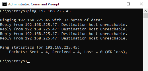
What Is The Reason to Receive Destination Host Unreachable Error Message?
If you want a one-sentence answer, look at the statement in the table.
Either there is no device with the IP Address you typed or your computer has a corrupted ARP table.
Let me explain with the example I showed above. When I sent Ping packets to the IP address 192.168.225.45 from my computer, it looked at the ARP table stored in my PC to fetch the MAC address associated with the destination IP Address.
You know the basic rule of network communication. You cannot send packets to an IP Address before finding the MAC address (Physical Address) of the destination device.
ARP table shows the MAC address of the devices assigned with the specific IP Address.
If you do not know this concept, there are tons of tutorials available about Address Resolution Protocol (ARP) on the Internet.
My computer could not find the ARP Address mapped to the IP Address 192.168.225.45 in the ARP table.
C:systosys>ping 192.168.225.45

Pinging 192.168.225.45 with 32 bytes of data:
Reply from 192.168.225.47: Destination host unreachable.
Reply from 192.168.225.47: Destination host unreachable.
Reply from 192.168.225.47: Destination host unreachable.
Reply from 192.168.225.47: Destination host unreachable.

Ping statistics for 192.168.225.45:
    Packets: Sent = 4, Received = 4, Lost = 0 (0% loss),

C:systosys>Destination Host Unreachable
So it displayed Reply from 192.168.225.47: Destination host unreachable as the response.
How to Fix Destination Host Unreachable?
If you do not know how to fix the reply from the x.x.x.x destination host unreachable message, follow the instructions provided below.
- Flush the ARP Cache
The first step to troubleshoot the Reply from 192.168.225.47: Destination host unreachable error is by deleting all entries in the ARP table on your computer.
- Open the Command Prompt as Administrator
- Type cmd on the Windows Search
- Right Click on the Command Prompt from the Search Window
- Click on the Run as Administrator option
- Type the following command and press enter
netsh interface ip delete arpcache
- Try ping the same IP address again and check for the issue.
- Open the Command Prompt as Administrator
- Run a Traceroute
If the problem persists, you should run a traceroute to pinpoint the problem location.
- Open Command Prompt
- Type the following command and press the enter key.
tracert 192.168.225.45
- Check the result to understand the reason for the Destination Host Unreachable message.

Why do I receive the ping reply Destination Host Unreachable? The traceroute result shows there is no such destination device.
- Disable the Firewall on your PC
In my experience, some users said faulty Firewall settings caused the Destination Host Unreachable error. So, I suggest you turn off the firewall on your laptop and check for the issue.
- Check the Status of the Destination Device and Test the Connection
If the destination device is in your reach, make sure the device is on. Make sure the network connection is fine.
You may unplug and replug the network cable to verify the connection status.

How to Check if Destination a Host Unreachable Error is Resolved?
It is very simple. You need to ping the same IP Address.
If the error is at the side of the IP Address, you should try to ping a different IP Address or domain name.
For example, check the command below to test whether the Destination a Host Unreachable Error fixed or not.
ping www.systosys.com
About The Author:
Siju George is a Cisco and Microsoft certified Network Engineer. He has been working in the Network Engineering field since 2006.
Siju George’s area of specialization is wireless and Cybersecurity.