In a Simulink® model, an algebraic loop occurs when a signal loop exists
with only direct feedthrough blocks within the loop. Direct feedthrough
means that Simulink needs the value of the block’s input signal to compute its output at the current
time step. Such a signal loop creates a circular dependency of block outputs and inputs in the
same time-step. This results in an algebraic equation that needs solving at each time-step, adding
computational cost to the simulation.
Some examples of blocks with direct feedthrough inputs are:
-
Math Function
-
Gain
-
Product
-
State-Space, when the D matrix coefficient is nonzero
-
Sum
-
Transfer Fcn, when the numerator and denominator are of the same order
-
Zero-Pole, when the block has as many zeros as poles
Nondirect feedthrough blocks maintain a State variable. Two examples are
Integrator and Unit Delay.
Tip
To determine if a block has direct feedthrough, read the
Characteristics section of the block reference page.
The figure shows an example of an algebraic loop. The Sum block is an
algebraic variable xa that is
constrained to equal the first input u minus
xa (for example, xa =
u –
xa).
The solution of this simple loop is xa =
u/2.
Mathematical Interpretation
Simulink contains a suite of numerical solvers for simulating ordinary
differential equations (ODEs), which are systems of equations that you can write
as
where x is the state vector and t is the independent
time variable.
Some systems of equations contain additional constraints that involve the independent
variable and the state vector, but not the derivative of the state vector. Such systems are
called differential algebraic equations (DAEs),
The term algebraic refers to equations that do not involve any
derivatives. You can express DAEs that arise in engineering in the semi-explicit form
where:
-
f and g can be vector functions.
-
The first equation is the differential equation.
-
The second equation is the algebraic equation.
-
The vector of differential variables is x.
-
The vector of algebraic variables is xa.
In Simulink models, algebraic loops are algebraic constraints. Models with algebraic loops
define a system of differential algebraic equations. Simulink solves the algebraic equations (the algebraic loop) numerically for
xa at each step of the ODE
solver.
The model in the figure is equivalent to this system of equations in semi-explicit
form:
At each step of the ODE solver, the algebraic loop solver must solve the algebraic
constraint for xa before calculating
the derivative x˙.
Physical Interpretation
Algebraic constraints:
-
Occur when modeling physical systems, often due to conservation laws, such as
conservation of mass and energy -
Occur when you choose a particular coordinate system for a model
-
Help impose design constraints on system responses in a dynamic system
Use Simscape™ to model systems that span mechanical, electrical, hydraulic, and other physical
domains as physical networks. Simscape constructs the DAEs that characterize the behavior of a model. The software
integrates these equations with the rest of the model and then solves the DAEs directly.
Simulink solves the variables for the components in the different physical domains
simultaneously, avoiding problems with algebraic loops.
Artificial Algebraic Loops
An artificial algebraic loop occurs when an atomic subsystem or Model block causes Simulink to detect an algebraic loop, even though the contents of the subsystem do not contain a direct feedthrough from the input to the output. When you create an atomic subsystem, all Inport blocks are direct feedthrough, resulting in an algebraic loop.
Start with the included model, which represents a simple proportional control of the plant described by
which can be rewritten in state-space form as
The system has neither algebraic variables nor direct feedthrough and does not contain an algebraic loop.
Modify the model as described in the following steps:
-
Enclose the Controller and Plant blocks in a subsystem.
-
In the subsystem dialog box, select Treat as atomic unit to make the subsystem atomic.
-
In the Diagnostics pane of the Model Configuration Parameters, set the Algebraic Loop parameter to
error.
When simulating this model, an algebraic loop occurs because the subsystem is direct feedthrough, even though the path within the atomic subsystem is not direct feedthrough. Simulation stops with an algebraic loop error.
How the Algebraic Loop Solver Works
When a model contains an algebraic loop, Simulink uses a nonlinear solver at each time step to solve the algebraic loop. The solver
performs iterations to determine the solution to the algebraic constraint, if there is one. As a
result, models with algebraic loops can run more slowly than models without algebraic
loops.
Simulink uses a dogleg trust region algorithm to solve algebraic loops. The tolerance used
is smaller than the ODE solver Reltol and Abstol. This is
because Simulink uses the “explicit ODE method” to solve Index-1 differential algebraic equations
(DAEs).
For the algebraic loop solver to work,
-
There must be one block where the loop solver can break the loop and attempt to solve the
loop. -
The model should have real double signals.
-
The underlying algebraic constraint must be a smooth function
For example, suppose your model has a Sum block with two inputs—one additive, the other
subtractive. If you feed the output of the Sum block to one of the inputs, you create an
algebraic loop where all of the blocks include direct feedthrough.
The Sum block cannot compute the output without knowing the input. Simulink detects the algebraic loop, and the algebraic loop solver solves the loop using an
iterative loop. In the Sum block example, the software computes the correct result this
way:
The algebraic loop solver uses a gradient-based search method, which requires continuous
first derivatives of the algebraic constraint that correspond to the algebraic loop. As a result,
if the algebraic loop contains discontinuities, the algebraic loop solver can fail.
For more information, see Solving Index-1 DAEs in MATLAB and Simulink
1
Trust-Region and Line-Search Algorithms in the Algebraic Loop Solver
The Simulink algebraic loop solver uses one of two algorithms to solve algebraic loops:
-
Trust-Region
-
Line-Search
By default, Simulink chooses the best algebraic loop solver and may switch between the two methods
during simulation. To explicitly enable automatic algebraic loop solver selection for your
model, at the MATLAB® command line, enter:
set_param(model_name, 'AlgebraicLoopSolver','Auto');
To switch to the trust-region algorithm, at the MATLAB command line, enter:
set_param(model_name, 'AlgebraicLoopSolver', 'TrustRegion');
If the algebraic loop solver cannot solve the algebraic loop with the trust-region
algorithm, try simulating the model using the line-search algorithm.
To switch to the line-search algorithm, at the MATLAB command line, enter:
set_param(model_name, 'AlgebraicLoopSolver', 'LineSearch');
For more information, see:
-
Shampine and Reichelt’s nleqn.m code
-
The Fortran program HYBRD1 in the User Guide for MINPACK-1 2
-
Powell’s “A Fortran subroutine for solving systems in nonlinear equations,” in
Numerical Methods for Nonlinear Algebraic Equations3 -
Trust-Region Methods for Nonlinear Minimization (Optimization Toolbox).
-
Line Search (Optimization Toolbox).
Limitations of the Algebraic Loop Solver
Algebraic loop solving is an iterative process. The Simulink algebraic loop solver is successful only if the algebraic loop converges to a
definite answer. When the loop fails to converge, or converges too slowly, the simulation exits
with an error.
The algebraic loop solver cannot solve algebraic loops that contain any of the
following:
-
Blocks with discrete-valued outputs
-
Blocks with nondouble or complex outputs
-
Discontinuities
-
Stateflow® charts
Implications of Algebraic Loops in a Model
If your model contains an algebraic loop:
-
You cannot generate code for the model.
-
The Simulink algebraic loop solver might not be able to solve the algebraic loop.
-
While Simulink is trying to solve the algebraic loop, the simulation can execute slowly.
For most models, the algebraic loop solver is computationally expensive for the first time
step. Simulink solves subsequent time steps rapidly because a good starting point for
xa is available from the previous
time step.
See Also
Compare Solvers | Zero-Crossing Detection | Algebraic Constraint | Descriptor State-Space
Related Topics
- Identify Algebraic Loops in Your Model
- Remove Algebraic Loops
- Modeling Considerations with Algebraic Loops
1 Shampine, Lawrence F., M.W.Reichelt, and J.A.Kierzenka. ”Solving Index-1 DAEs in MATLAB
and Simulink.”Siam Review.Vol.18,No.3,1999,pp.538–552.
2 More,J.J.,B.S.Garbow, and K.E.Hillstrom. User guide for MINPACK-1.
Argonne, IL:Argonne National Laboratory,1980.
3 Rabinowitz, Philip, ed. Numerical Methods for Nonlinear Algebraic
Equations, New York: Gordon and Breach Science Publishers, 1970.
-
Dmitry_math
- Пользователь
- Сообщения: 138
- Зарегистрирован: Вс янв 20, 2008 11:54 am
Решение простой модели
Доброго всем дня!
Господа представте такой случай, я создаю простейшую модель с обратной связью, как на картинке.
Причем все настройки модели по умолчанию, т.е. я ничего не менял, но при запуске модели пишется такая ошибка:
Simulink cannot solve the algebraic loop containing ‘MoodelOneNeuron/Sum1’ at time 0.0 using the TrustRegion-based algorithm due to one of the following reasons: the model is ill-defined i.e., the system equations do not have a solution; or the nonlinear equation solver failed to converge due to numerical issues.
To rule out solver convergence as the cause of this error, either
a) switch to LineSearch-based algorithm using
set_param(‘MoodelOneNeuron’,’AlgebraicLoopSolver’,’LineSearch’)
b) reducing the VariableStepDiscrete solver RelTol parameter so that the solver takes smaller time steps.
If the error persists in spite of the above changes, then the model is likely ill-defined and requires modification.
Отчего в элементе Sum (там где просто складываются сигнала, это сложение не происходит?
Спасибо!
Занимаюсь математическим моделированием.
-
chernykh
- Эксперт
- Сообщения: 4526
- Зарегистрирован: Ср сен 22, 2004 4:49 pm
Сообщение chernykh » Пт фев 25, 2011 9:00 am
А чему, по-вашему, должен быть равен сигнал на выходе?
-
Dmitry_math
- Пользователь
- Сообщения: 138
- Зарегистрирован: Вс янв 20, 2008 11:54 am
экспонента
Сообщение Dmitry_math » Пт фев 25, 2011 10:22 am
chernykh писал(а):А чему, по-вашему, должен быть равен сигнал на выходе?
Я полаю, что увеличения сигнала по экспоненте! Разве не так?
Все должно быть просто, есть источник постоянного сигнала, положим у уровнем 1, этот сигнал поступает на блок Sum. У блока Sum есть два входа и выход, так вот если выход блока Sum соединить с один из входов, то получится следующее выходной сигнал от блока Sum поступает на вход блока Sum где он складывается с входным сигналом от источника постоянного сигнала с уровнем 1. т.е. происходит увеличение входного сигнала на самого себя.
Правильно ли я понимаю эту ситуацию?
Занимаюсь математическим моделированием.
-
chernykh
- Эксперт
- Сообщения: 4526
- Зарегистрирован: Ср сен 22, 2004 4:49 pm
Сообщение chernykh » Пт фев 25, 2011 2:50 pm
Я полаю, что увеличения сигнала по экспоненте! Разве не так?
Нет.
То, что вы нарисовали есть графическое изображение уравнения:
y(ti) = x(ti) + y(ti)
Если сможете решить его, значит и Simulink должен это сделать.
есть источник постоянного сигнала, положим у уровнем 1, этот сигнал поступает на блок Sum. У блока Sum есть два входа и выход, так вот если выход блока Sum соединить с один из входов, то получится следующее выходной сигнал от блока Sum поступает на вход блока Sum где он складывается с входным сигналом от источника постоянного сигнала с уровнем 1. т.е. происходит увеличение входного сигнала на самого себя.
То, что Вы здесь написали есть совершенно другое уравнение, а именно:
y(ti) = x(ti) + y(ti-1) , т.е.
значение выхода на текущем расчетном шаге есть значение входного сигнала на текущем расчетном шаге плюс выходное значение сумматора на предыдущем расчетном шаге.
Т.о., чтобы получить, то, что Вы хотите нужно в канал обратной связи поставить блок задержки сигнала на один расчетный шаг.
И это, разумеется, будет не экспонента.
-
Dmitry_math
- Пользователь
- Сообщения: 138
- Зарегистрирован: Вс янв 20, 2008 11:54 am
Сообщение Dmitry_math » Пт фев 25, 2011 4:25 pm
chernykh писал(а):
Я полаю, что увеличения сигнала по экспоненте! Разве не так?
Нет.
То, что вы нарисовали есть графическое изображение уравнения:
y(ti) = x(ti) + y(ti)
Если сможете решить его, значит и Simulink должен это сделать.есть источник постоянного сигнала, положим у уровнем 1, этот сигнал поступает на блок Sum. У блока Sum есть два входа и выход, так вот если выход блока Sum соединить с один из входов, то получится следующее выходной сигнал от блока Sum поступает на вход блока Sum где он складывается с входным сигналом от источника постоянного сигнала с уровнем 1. т.е. происходит увеличение входного сигнала на самого себя.
То, что Вы здесь написали есть совершенно другое уравнение, а именно:
y(ti) = x(ti) + y(ti-1) , т.е.
значение выхода на текущем расчетном шаге есть значение входного сигнала на текущем расчетном шаге плюс выходное значение сумматора на предыдущем расчетном шаге.
Т.о., чтобы получить, то, что Вы хотите нужно в канал обратной связи поставить блок задержки сигнала на один расчетный шаг.
И это, разумеется, будет не экспонента.
Спасибо все заработало! И действительно не экспонента!
Занимаюсь математическим моделированием.
-
Dmitry_math
- Пользователь
- Сообщения: 138
- Зарегистрирован: Вс янв 20, 2008 11:54 am
Уточнение
Сообщение Dmitry_math » Пт фев 25, 2011 7:05 pm
Правильно ли я понимаю концепцию этого примера?
Есть модельное время как некая последовательность значений (отчетов). Блок с постоянным сигналом в каждый момент времени (понимаем отчета модельного времени) посылает сигнал (с уровнем 1) в блок сумматора Sum. Блок Sum за единицу отчета выполняет одну операцию сложения, т.е. в момент времени 0 он складывает сигналы на двух своих входах (одна операция), в момент времени 1 он опять складывает сигналы на своих входах и т.д.
В моей первоначальной модели возникла ошибка в следствии того, что на сумматор в начальный момент времени поступил только один сигнал, ибо второй сигнал (который является выходным сигналом сумматора, т.е. обратная связь) ещё не существует.
Так ли все?
И если нет, то какую функцию несет в себе блок задержки сигнала?
Спасибо!
Занимаюсь математическим моделированием.
-
chernykh
- Эксперт
- Сообщения: 4526
- Зарегистрирован: Ср сен 22, 2004 4:49 pm
Сообщение chernykh » Сб фев 26, 2011 7:59 am
Правильно ли я понимаю концепцию этого примера?
Нет. Модель имеет алгебраический контур. Т.е. контур в котором нет инерционных элементов. Simulink пытается выполнить расчет этого контура (решить алгебраическое уравнение). Но в приведенном примере это невозможно. Можете изменить знак сигнала обратной связи на «-» и посмотреть, что получится.
Блок Delay, поставленный в цепь обратной связи, обеспечивает обесчивает тот алгоритм о котором Вы пишете (но это уже другое уравнение):
Блок с постоянным сигналом в каждый момент времени (понимаем отчета модельного времени) посылает сигнал (с уровнем 1) в блок сумматора Sum. Блок Sum за единицу отчета выполняет одну операцию сложения, т.е. в момент времени 0 он складывает сигналы на двух своих входах (одна операция), в момент времени 1 он опять складывает сигналы на своих входах и т.д.
http://www.mathworks.com/help/toolbox/s … #bsjdimy-1
-
Dmitry_math
- Пользователь
- Сообщения: 138
- Зарегистрирован: Вс янв 20, 2008 11:54 am
Спасибо!
Сообщение Dmitry_math » Сб фев 26, 2011 8:30 pm
Спасибо! Немного разобрался.
Занимаюсь математическим моделированием.
MY PROBLEM
I have a SIMULINK model that has got a feeback loop aka Algebraic Loops that is causing error in the simulation. My original solver configuration was Fixed-Step with Dormand-Prince (Order 5). I also tried Fixed-Step with Order 3 (Runga-Kutta). It still has not resolved the issue.
MY QUESTION
Is there any way to resolve algebraic loop without altering the original performance or design of the circuit too much?
CLARIFICATION FOR THE QUESTION
I am sure that there will be a way to solve this. However, I don’t want it to compromise the original performance of the circuit. Moreover, it is a customer-supplied data and it seems that they have managed to work this out as fine. I simply require somebody to point me to the right direction regarding how to solve this.
MY Approach so far
I tried to break the loop using:
i) Switch (if ip = 0, op = 0; if ip = 1, op = 1) I know it is stupid but it is a different block that breaks the loop.
ii) Logic gate (XORing the feedback signal with 0).
Unfortunately, I don’t know how to do a zero-order hold unit delay loop that seems to be another commonly prescribed solution for this kind of problem. But I believe that may cause issues with my model’s originally intended performance.
I have posted a query on Mathworks website, but no response so far. SO I thought…why not stackoverflow? Below is the image.
Algebraic Loops
Some Simulink blocks have input ports with direct feedthrough. This means that the output of these blocks cannot be computed without knowing the values of the signals entering the blocks at these input ports. Some examples of blocks with direct feedthrough inputs are as follows:
- The Math Function block
- The Gain block
- The Integrator block’s initial condition ports
- The Product block
- The State-Space block when there is a nonzero D matrix
- The Sum block
- The Transfer Fcn block when the numerator and denominator are of the same order
- The Zero-Pole block when there are as many zeros as poles
An algebraic loop generally occurs when an input port with direct feedthrough is driven by the output of the same block, either directly, or by a feedback path through other blocks with direct feedthrough. (See Nonalgebraic Direct-Feedthrough Loops for an example of an exception to this general rule.) An example of an algebraic loop is this simple scalar loop.
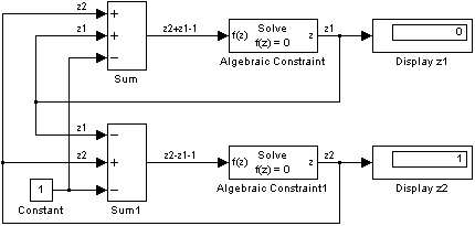
Mathematically, this loop implies that the output of the Sum block is an algebraic state z constrained to equal the first input u minus z (i.e. z = u — z). The solution of this simple loop is z = u/2, but most algebraic loops cannot be solved by inspection. It is easy to create vector algebraic loops with multiple algebraic state variables z1, z2, etc., as shown in this model.
The Algebraic Constraint block is a convenient way to model algebraic equations and specify initial guesses. The Algebraic Constraint block constrains its input signal F(z) to zero and outputs an algebraic state z. This block outputs the value necessary to produce a zero at the input. The output must affect the input through some feedback path. You can provide an initial guess of the algebraic state value in the block’s dialog box to improve algebraic loop solver efficiency.
A scalar algebraic loop represents a scalar algebraic equation or constraint of the form F(z) = 0, where z is the output of one of the blocks in the loop and the function F consists of the feedback path through the other blocks in the loop to the input of the block. In the simple one-block example shown on the previous page, F(z) = z — (u — z). In the vector loop example shown above, the equations are
-
z2 + z1 - 1 = 0
z2 - z1 - 1 = 0
Algebraic loops arise when a model includes an algebraic constraint F(z) = 0. This constraint might arise as a consequence of the physical interconnectivity of the system you are modeling, or it might arise because you are specifically trying to model a differential/algebraic system (DAE).
When a model contains an algebraic loop, Simulink calls a loop solving routine at each time step. The loop solver performs iterations to determine the solution to the problem (if it can). As a result, models with algebraic loops run slower than models without them.
To solve F(z) = 0, the Simulink loop solver uses Newton’s method with weak line search and rank-one updates to a Jacobian matrix of partial derivatives. Although the method is robust, it is possible to create loops for which the loop solver will not converge without a good initial guess for the algebraic states z. You can specify an initial guess for a line in an algebraic loop by placing an IC block (which is normally used to specify an initial condition for a signal) on that line. As shown above, another way to specify an initial guess for a line in an algebraic loop is to use an Algebraic Constraint block.
Whenever possible, use an IC block or an Algebraic Constraint block to specify an initial guess for the algebraic state variables in a loop.
Nonalgebraic Direct-Feedthrough Loops
There are exceptions to the general rule that all loops comprising direct-feedthrough blocks are algebraic. The exceptions are
- Loops involving triggered subsystems
- A loop from the output to the reset port of an integrator
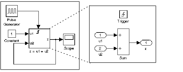
A triggered subsystem holds its outputs constant between trigger events (see Triggered Subsystems). Thus, a solver can safely use the output from the system’s previous time step to compute its input at the current time step. This is, in fact, what a solver does when it encounters a loop involving a triggered subsystem, thus eliminating the need for an algebraic loop solver.
Note
Because a solver uses a triggered subsystem’s previous output to compute feedback inputs, the subsystem, and any block in its feedback path, can exhibit a one-sample-time delay in its output. When simulating a system with triggered feedback loops, Simulink displays a warning to remind you that such delays can occur.
Consider, for example, the following system.
.
This system effectively solves the equation
-
z = 1 + u
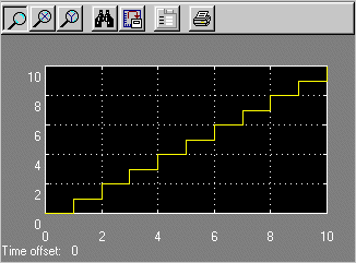
where u is the value of z the last time the subsystem was triggered. The output of the system is a staircase function as illustrated by the display on the system’s scope.
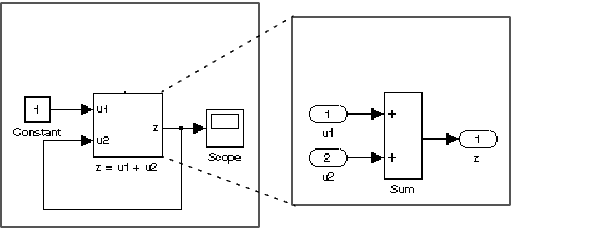
Now consider the effect of removing the trigger from the system shown in the previous example.
In this case, the input at the u2 port of the adder subsystem is equal to the subsystem’s output at the current time step for every time step. The mathematical representation of this system
-
z = z + 1
reveals that it has no mathematically valid solution.
Highlighting Algebraic Loops
You can cause Simulink to highlight algebraic loops when you update, simulate, or debug a model. Use the ashow command to highlight algebraic loops when debugging a model.
To cause Simulink to highlight algebraic loops that it detects when updating or simulating a model, set the Algebraic loop diagnostic on the Diagnostics pane of the Simulation parameters dialog box to Error (see Configuration options for more information). This causes Simulink to display an error dialog (the Diagnostic Viewer) and recolor portions of the diagram that represent the algebraic loops that it detects. Simulink uses red to color the blocks and lines that constitute the loops. Closing the error dialog restores the diagram to its original colors.
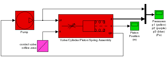
For example, he following figure shows the block diagram of the hydcyl demo model in its original colors.
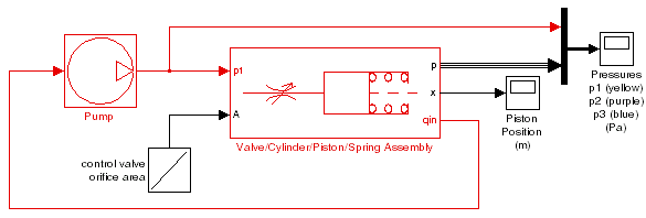
The following figure shows the diagram after updating when the Algebraic loop diagnostic is set to Error.
In this example, Simulink has colored the algebraic loop red, making it stand out from the rest of the diagram.
 |
Zero-Crossing Detection | Modeling and Simulating Discrete Systems |  |
$begingroup$
I have been developing a simulation of the field oriented control of the three phase induction motor.
The simulation is developed in the Scilab/Xcos (v5.5.2) which is a free of charge Matlab/Simulink like
software. The diagram of my simulation in the Xcos toolbox looks like this
As you can see the simulation basically consists of below mentioned main blocks:
-
IM model
Dynamic model of the three phase induction motor
-
Control algorithm
Produces components of the reference stator voltage in the stationary reference
frame based on chosen control algorithm (open loop scalar control x field oriented control) -
Observer
Calculates estimate of the components of the unmeasurable rotor flux and based on that calculates
orientation of the space vector of the rotor flux for the field oriented control algorithm
The block a) is a continuous time domain system and the blocks b) and c) are discrete time domain systems (they model software). Due to that arrangement the blocks b) and c) are separeted from the continous world (plant domain) via the ADC converter (modeled via sample and hold blocks) at their inputs and via the DAC conveter (first order hold algorithm) at their outputs.
The simulation has been developed in two steps:
-
induction motor controlled via open loop scalar control algorithm
Simulation works correctly because no feedback is present
-
induction motor controlled via field oriented control algorithm
At first I have encountered a problem with the algebraic loop error
Based on my experience with the Matlab/Simulink I have inserted a time delay into the control loop
(please see the blocks «Delay» in the ADCs part)I have set the delay of these blocks to a small fraction of the sampling period ($T_s =
0.0001,mathrm{s}$ and the delay has been set to $0.1cdot T_s$). Insertion of that delay has
resolved the problem with the algebraic loop but it has also caused two unwelcome facts. Firstly the
state estimation error in the observer is high despite the «small» value of the delay. Secondly the
delay insertion caused huge increase of the simulation time.I have also thought about simulation diagram rearangement to avoid the algebraic loop inherently but I
can’t see any way how to do that — ultimately I simulate the feedback loop.
Does anybody have any idea how to split the algebraic loop in such a manner which does
not corrupt the state estimation process in the observer and also does not increase the simulation time
too much?
asked Oct 9, 2020 at 12:46
$endgroup$
1
$begingroup$
Algebraic loops occur when the present-state calculations depend on the present-state output — how can it provide a calculation if it does not have an initial condition?
How to break such loops can be as simple as placing a block that provides an initial output.
- Memory block (delay block in XCos)
- Transfer function $frac{1}{1mu s + 1} $
Both provide an initial output of 0 and thus permit the downstream calculations to initialize to then feed back into itself.
If your solver is fixed-step then a Memory block (Delay block) is the best solution as it delays the signal by 1 step. If however the solver is variable then a transfer function with a suitably high time constant is the better solution.
Where to place such block? on all feedbacks used by the control loop
answered Oct 9, 2020 at 13:42
$endgroup$
2


