2.1
2
Software
LC display
Description
1
Different syringe recognition
2
Different FP- and CMP condition
3
Rate of FP- and CMP different
4
Different function mode
5
Different rate of delivery
6
Different target volume
7
Different step volume (low)
8
Different motor steps
19
State/motor state
20
Invalid normal state
21
return from PlcMain
22
Unexpected reset
28
No sync at Plc_Down
29
No sync at Plc_On
30
Different CMP/FP mode ports
31
Invalid mode ports
32
Invalid variable values
33
Error in ROM test
34
Different software version
40
Unexpected interrupt
49
Faulty sensor sync
51
Motor on during reverse run
52
Step cumulation > 10 steps
53
Illegal setting of Mot_Ok
54
Different recognition of direction of rotation
55
Reverse polarity of motor
Table 2 — 1 (Part 1 of 2)
2 — 2
In case of a unit malfunction a continuous signal is activated, and
the function processor displays an alarm and an error code. The
error code of the control microprocessor can be queried with the
F button. Please state both error codes if you have any questions.
Acknowledge alarm and switch device off.
Device Alarms of the Function Processor
Perfusor® compact, 2.1 gb
 Loading…
![]()
Perfusor® compact S
Service-Manual
Version 2.1 english

0
This Service-Manual is valid for
This Service Manual is available under the following part number:
Languages of this Manual
The complete Service-Manual contains the following pages:
Perfusor® compact S (200 — 240 V) . . . . . . . . . . . . . . . 0871 4843
Perfusor® compact S, English . . . . . . . . . . . . . . . . . . . . 8713 9114
The Service Manual for this unit can be supplied in the following languages:
Perfusor® compact S, German . . . . . . . . . . . . . . . . . . . . 8713 9113 Perfusor® compact S, USA . . . . . . . . . . . . . . . . . . . . . . .8713 9115
Page 0-1 to page 0-10
Page 1-1 to page 1-4
Page 2-1 to page 2-8
Page 3-1 to page 3-14
Page 4-1 to page 4-18
Page 5-1 to page 5-8
Page 6-1 to page 6-2
Page 7-1 to page 7-2
Page 8-1 to page 8-6
Page 9-1 to page 9-2
Page 10-1 to page 10-2
Page 11-1 to page 11-2
Page A-1 to page A-2
|
0 — 2 |
Perfusor® compact S, 2.1 gb |

Table of Contents 0
|
Important Preliminary Remarks |
Service Work |
Page |
0 — 5 |
|
Technical Safety Checks |
Page |
0 — 5 |
|
|
Current Versions |
Page |
0 — 5 |
|
|
Revision Service |
Page |
0 — 5 |
|
|
Quality Management |
Page |
0 — 6 |
|
|
Checks and Repair |
Page |
0 — 6 |
|
|
Notes on ESD |
Page |
0 — 6 |
|
|
Spare Parts and Test Equipment |
Page |
0 — 7 |
|
|
Setting Off |
Page |
0 — 7 |
|
|
List of Abbreviations |
Page |
0 — 8 |
|
|
Contact Persons |
Technical Training |
Page |
0 — 9 |
|
Entry for Technical Training |
Page |
0 — 9 |
|
|
Ordering of Spare Parts and Test Equipment |
Page |
0 — 9 |
|
|
Service Hotline |
Page |
0 — 9 |
|
|
Return of Spare Parts and Test Equipment |
Page |
0 — 9 |
|
|
Safety Officer |
|||
|
(§ 30 MPG) |
Page |
0 — 9 |
|
|
Translation |
Page |
0 — 9 |
|
|
System Overview |
Physical Construction |
Page |
1 — 1 |
|
Function |
Page |
1 — 2 |
|
|
Accessories |
Page |
1 — 3 |
|
|
Software |
Approved Software Versions |
Page |
2 — 1 |
|
Version Display during Switch-On Test |
Page |
2 — 1 |
|
|
Extended Version Display during Switch-On Test |
Page |
2 — 2 |
|
|
Error Messages and Alarms |
Page |
2 — 3 |
|
|
Service Program |
Current Service Program |
Page |
3 — 1 |
|
Introduction |
Page |
3 — 1 |
|
|
Working with the Service Program |
Page |
3 — 2 |
|
|
What to Do if… (Troubleshooting) |
Page |
3 — 5 |
|
|
Menu Commands (Overview) |
Page |
3 — 7 |
|
|
Procedural Instructions for Inspection |
|||
|
after Operation of the Service Program |
Page |
3 — 11 |
|
|
Checklist after Operation of the Service Program |
Page |
3 — 13 |
|
|
Unit Elements |
Fundamental Repair Information |
Page |
4 — 1 |
|
Syringe Table and Quick Reference Guide |
Page |
4 — 4 |
|
|
Syringe Holder |
Page |
4 — 4 |
|
|
Unit Feet |
Page |
4 — 5 |
|
|
Battery Compartment Cover |
Page |
4 — 5 |
|
|
Snap-in Clip |
Page |
4 — 6 |
|
|
A-Module |
Page |
4 — 6 |
|
|
LS-Clip |
Page |
4 — 7 |
|
|
E-Module |
Page |
4 — 8 |
|
|
N-Module |
Page |
4 — 9 |
|
|
Housing Upper Part, Complete |
Page |
4 — 9 |
|
|
Carrying Handle |
Page |
4 — 10 |
|
|
Drive |
Page |
4 — 11 |
|
Perfusor® compact S, 2.1 gb |
0 — 3 |

|
Axial Positioner |
Page |
4 — 12 |
||
|
Drive Board |
Page |
4 — 12 |
||
|
Drive Head and Holder |
Page |
4 — 14 |
||
|
Clip |
Page |
4 — 17 |
||
|
Drive Head Housing |
Page |
4 — 18 |
||
|
Housing Bottom Part, Complete |
Page |
4 — 18 |
||
|
Checks after Repair |
Check List for Checks after Repair |
Page |
5 |
— 1 |
|
Visual Inspection |
Page |
5 |
— 2 |
|
|
Functional Inspection |
Page |
5 |
— 2 |
|
|
Electrical Safety |
Page |
5 |
— 8 |
|
|
Syringe / Syringe Selection |
Page |
5 |
— 8 |
|
|
Adhesive Label Factory Setting |
Page |
5 |
— 8 |
|
|
Maintenance |
Page |
6 |
— 1 |
|
|
Technical Safety Check TSC |
Page |
7 |
— 1 |
|
|
Procedural Instructions on the TSC |
Visual Inspection |
Page |
8 |
— 1 |
|
Functional Inspection |
Page |
8 |
— 2 |
|
|
Syringes |
Page |
8 |
— 3 |
|
|
Pressure Cut-Off |
Page |
8 |
— 3 |
|
|
Electrical Safety |
Page |
8 |
— 5 |
|
|
Accessories |
Page |
8 |
— 5 |
|
|
Test Equipment and Special Tools |
Page |
9 |
— 1 |
|
|
Spare Parts List |
Page |
10 |
— 1 |
|
|
Index |
Page |
11 |
— 1 |
|
|
Appendix |
Revision Service-Documentation |
Page |
A — 1 |
|
|
Current Information |
Page |
A — 1 |
|
0 — 4 |
Perfusor® compact S, 2.1 gb |

Important Preliminary Remarks 0
Service Work |
The present manual is for your information only. The possession of |
|
this manual does not authorize the performance of service work. |
|
|
Service tasks may only be executed by persons, who |
|
|
— have received appropriate training on the system from |
|
|
B. Braun |
|
|
— are included in the revision service |
|
|
— possess the necessary test equipment and mechanical aids, |
|
|
and |
|
|
— fulfill the personal requirements (training and knowledge). |
|
Technical Safety Checks |
The user is obliged to perform or to have performed the Technical |
|
Safety Checks on those medial products for which these checks |
|
|
have been prescribed by the manufacturer and to carry them out |
|
|
according to the indications of the manufacturer as well as the |
|
|
generally approved technical standards while adhering to the pe- |
|
|
riods stated (§ 6 MP BetreibV). |
|
|
B. Braun also recommends training on the Technical Safety |
|
|
Checks, or to perform at least the steps indicated in the current |
|
|
version of the manual, as: |
|
|
— the TSC requires that the instructions in the manuals are ob- |
|
|
served |
|
|
— the manuals are a reference for measurements |
|
|
— depending on the unit type, the Service Program must be |
|
|
called which may lead to a dangerous unit condition in case |
|
|
of inappropriate operation. Furthermore, a special service |
|
|
connector may be necessary. |
|
Current Versions |
This manual version corresponds to the state when the manual |
|
was written. B Braun reserves the right to make technical modifi- |
|
|
cations. The state of the revision is indicated by the index number |
|
|
in the footer of every page. |
|
Revision Service |
The possession of this manual does not automatically mean inclu- |
|
sion in the revision service. You will be included in the revision |
|
|
service after: |
|
|
— technical training by B. Braun Melsungen or |
|
|
— a written order placed with the sales department of B. Braun |
|
|
(fee required). |
|
Perfusor® compact S, 2.1 gb |
0 — 5 |

|
0 |
Important Preliminary Remarks |
Responsibility of the Manufacturer |
The manufacturer, person who assembles, installs or imports the |
|
device can only be held responsible for safety, reliability and per- |
|
|
formance if |
|
|
— mounting, enhancements, new settings, changes or repairs |
|
|
are carried out by duly authorized persons, |
|
|
— the electrical installation in the corresponding room meets |
|
|
the requirements of the VDE 0107, VDE 0100 part 710 or |
|
|
IEC 60364-7-710 and the national standards, |
|
|
— the device is used in accordance with the instructions for use |
|
|
and the Service Manual, |
|
|
— the Technical Safety Checks are performed at regular inter- |
|
|
vals, |
|
|
— a current manual which corresponds to the revision state is |
|
|
used when carrying out maintenance, repair and service, |
|
|
— the service technician takes part in the revision service, |
|
|
— the technician has participated in a technical training course |
|
|
for the specific B. Braun unit. |
|
Quality Management |
B. Braun is certified in accordance with DIN EN ISO 9001 and |
|
ISO 13485. This certification also includes maintenance and serv- |
|
|
ice. |
|
|
The unit has the CE label. The CE label confirms that the device |
|
|
corresponds to the “Directive of the Council for Medical Products |
|
|
93/42/EC” of June 14, 1993. |
|
Checks and Repair |
Training may only be performed by B. Braun. The possession of the |
|
manual does not authorize the performance of repairs. The in- |
|
|
structions on electrostatic sensitive components (ESD standards) |
|
|
must be observed. |
|
|
After repair a device check or diagnosis is to be carried out. |
|
Notes on ESD |
Semiconductors can be destroyed by electrostatic discharge. Es- |
|
pecially MOS components can be damaged by interference from |
|
|
electrostatic fields, even without discharge via contact. This type |
|
|
of damage is not immediately recognizable. Unit malfunctions |
|
|
can even occur after a longer period of operation. |
|
0 — 6 |
Perfusor® compact S, 2.1 gb |

|
Important Preliminary Remarks |
0 |
Fig.: 0 — 1
Spare Parts and Test Equipment
Setting Off
Each workstation must be equipped according to the recommendations with the necessary static protective measures, if ESD components or boards are handled.
Each workstation must be equipped with a conductive table surface. The conductive surface, the soldering iron or the soldering stations must be grounded via protective resistors.
Chairs must be of antistatic design. The floor or floor mats should be of electrically conductive material.
Personnel must wear conductive wristbands which are connected to a central ground potential via protective resistors, e.g. the ground contact of a wall outlet. Furthermore it is recommended that personnel wear cotton clothing and electrically conductive shoes to prevent electrostatic charge.
Only use original spare parts from the manufacturer. Do not tamper with assembly groups which can only be exchanged completely. The spare parts required are listed in Section 9.
Service personnel are responsible for the calibration of their test equipment. Original test equipment can be calibrated at the works of B. Braun. Further information is available upon request.
Additional notes and warnings are set off as follows:
Note
Is used for additional or special notes concerning information and working steps.
CAUTION
Is used for working steps which may result in damage to the unit, system or to a connected device.
WARNING
IS USED FOR WORKING STEPS WHICH MAY RESULT IN PERSONAL INJURY.
References to chapters are shown as follows (see “Setting Off“ pg. 0 — 
References to figures and tables are shown as follows Fig.: 2 — 3 or Table 2 — 1
|
Perfusor® compact S, 2.1 gb |
0 — 7 |

|
0 |
Important Preliminary Remarks |
|
References to item numbers in figures are shown as follows |
||
|
(Fig.: 1 — 1 / Item 1) |
||
|
In this case “Fig.: 1 – 1“ is the figure number and “Item 1“ the item |
||
|
number within the figure. |
||
|
When the Service Manual is stored as pdf-file, these references |
||
|
are displayed green. Click with the mouse button on a reference |
||
|
to jump to the corresponding source. |
||
|
Menu commands are described as: |
||
|
Menu File. |
||
List of Abbreviations |
Abbreviations which are not generally known, but are used in this |
|
|
manual, are listed below. |
||
|
A-Module |
Analog Module |
|
|
DMS |
Strain gauge |
|
|
E-Module |
Electronic Module |
|
|
ESD |
Electrostatic Discharge |
|
|
IfU |
Instructions for Use |
|
|
LCD |
Liquid Crystal Display |
|
|
MFC |
Multi-Function Connector |
|
|
PS-Module |
Power Supply Module |
|
|
TSC |
Technical Safety |
|
|
Checks |
||
|
TEMP |
Temperature |
|
0 — 8 |
Perfusor® compact S, 2.1 gb |

Contact Persons 0
Technical Training |
Via local representative. |
|
Entry for Technical Training |
Application for a technical training course must be made via the |
|
|
responsible representative. |
||
Ordering of Spare Parts and Test Equipment |
Please contact your local B. Braun subsidary. |
|
|
International Technicians (Intercompany) |
||
|
Nadja Machal |
||
|
Fax: |
+49 5661 / 75 -47 89 |
|
|
e-mail: |
nadja.machal@bbraun.com |
|
Service Hotline |
Karl Tippel, Tanja Kördel |
|
|
Phone: |
+49 5661 / 71 — 35 25 |
|
|
Fax: |
+49 5661 / 71 — 35 26 |
|
|
e-mail: |
karl.tippel@bbraun.com |
|
|
e-mail: |
tanja.koerdel@bbraun.com |
|
Return of Spare Parts and Test Equipment |
B. Braun Melsungen AG |
|
|
Schwarzenberger Weg 73-79 |
||
|
Wareneingang Werk C |
||
|
34 212 Melsungen |
||
|
Germany |
||
|
Safety Officer |
Dr. Dirk Woitaschek |
|
|
(§ 30 MPG) |
e-mail: dirk.woitaschek@bbraun.com |
|
Translation |
PAS GmbH, Brückner GmbH, Germany |
|
Perfusor® compact S, 2.1 gb |
0 — 9 |

|
0 — 10 |
Perfusor® compact S, 2.1 gb |

System Overview 1
Physical Construction
The Perfusor® compact S is a compact, stacking, portable and light-weight syringe pump which is used for precise dosing of small to high volumes of fluids in infusion and alimentary therapies.
The standard delivery rate range is 0.1 to 200 ml/h (in increments of 0.01 ml/h).
All important information is displayed on an LCD-display. The Perfusor® compact S features: simple operation via a membrane keyboard and a microprocessor-controlled function process and monitoring. The Perfusor® compact S has a long service life and is easy-to-service due to its modular design. Individual modules can be replaced easily and quickly, and the Service Program runs on a PC.
.
|
Carrying handle |
Membrane keyboard |
Battery compartment |
MFC-socket |
|||||||||||||||||||
|
LCD-display |
Axial positioner Drive head with lock |
Mains connection |
||
|
Syringe holder |
Snap-in clip |
|||
|
and push-button sensor |
||||
|
(on both sides) |
||||
|
Axial positioner |
||||
|
Syringe table |
Type plate |
Clamp |
||
and quick reference guide
Unit feet
View from below
Fig.: 1 — 1
|
Perfusor® compact S, 2.1 gb |
1 — 1 |

Function |
The electronics of the Perfusor® compact S consists of the follow- |
|
|
ing components: |
||
|
1. |
A-Module with MFC-board as the central power supply and |
|
|
interface |
||
|
2. |
E-Module as operating and control unit |
|
|
3. |
Drive unit, consisting of |
|
|
— drive board with the complete sensor technology, light |
barriers for syringe preand end-alarm, syringe size recognition and motor operation control
— pressure sensor board with sensor for an inserted syringe and force sensor amplifier
— positive locking sensor board with sensor for the frictional connection between nut and spindle of the drive
— pressure sensor (pressure).
|
Fig.: 1 — 2 |
Block diagram |
|||||||||||||||||||||||||||||||||
|
1 — 2 |
Perfusor® compact S, 2.1 gb |

Accessories |
Designation |
Ord. No. |
|
Unit connecting lead 220-240 V . . . . . . . . . . . . . . . . . |
3450 2718 |
|
|
Pole clamp (universal clamp, rotating) . . . . . . . . . . . . |
3450 9054 |
|
|
Battery pack . . . . . . . . . . . . . . . . . . . . . . . . . . . . . . . . . |
3450 1690 |
|
Perfusor® compact S, 2.1 gb |
1 — 3 |

|
1 — 4 |
Perfusor® compact S, 2.1 gb |

Software 2
Approved Software Versions
|
Position |
1 |
2 |
3 |
4 |
5 |
6 |
7 |
8 |
9 |
|||||
|
Digit |
P |
L |
B |
E |
0 |
0 |
0 |
1 |
4 |
|||||
|
Revision level |
||||||||||||||
|
Hardware identification |
||||||||||||||
|
Software group |
||||||||||||||
|
Hardware group |
||||||||||||||
|
Perfusor® compact S |
||||||||||||||
|
Fig.: 2 — 1 |
||||||||||||||
The software and hardware revision level is displayed on the LCDdisplay when the unit is switched on. The characters on the display must correspond with the indication on the instructions for use.
|
Version PLBD00010 |
first approved software version |
|
Version PLBE00010 |
with Dianet Star |
|
Version PLBE00011 |
with Dianet Star and modified |
|
signalling in case of a missing |
|
|
battery |
|
|
Version PLBE00013 |
Dianet Star, enhanced |
|
Version PLBE00014 |
with Dianet Star and modified |
|
syringe size recognition |
Version Display during Switch-On Test
1.Switch on unit.
2.The following information is displayed one after the other on screen:
88:8.8
11:1.1
22:2.2
|
55:5.5 |
|
|
b:E. |
Reference to the instructions |
|
for use (hardand soft- |
|
|
ware group) |
3.The Perfusor® compact S switches over to normal operation.
|
Perfusor® compact S, 2.1 gb |
2 — 1 |

2 Software
Extended Version Display during Switch-On Test
1.Switch on unit.
2.Press the F button and keep the button pressed during normal switch-on test. The following information (examples) appears on screen after the information displayed during normal switch-on test:
|
00 |
Hardware identification |
|
(no importance for the |
|
|
Perfusor® compact S) |
|
|
0101 |
Software version |
|
0063 |
0063 operating hours |
|
0004 |
Maintenance interval timer |
3.Release the F button to exit. The Perfusor® compact S switches over to normal operation.
|
2 — 2 |
Perfusor® compact S, 2.1 gb |

Software 2
Error Messages and Alarms |
In case of a unit malfunction a continuous signal is activated, and |
|
|
the function processor displays an alarm and an error code. The |
||
|
error code of the control microprocessor can be queried with the |
||
|
F button. Please state both error codes if you have any questions. |
||
|
Acknowledge alarm and switch device off. |
||
|
Device Alarms of the Function Processor |
||
|
LCD-Display |
Description |
|
|
1 |
Different syringe recognition |
|
|
2 |
Different FPand CMP condition |
|
|
3 |
Rate of FPand CMP different |
|
|
4 |
Different function mode |
|
|
5 |
Different rate of delivery |
|
|
6 |
Different target volume |
|
|
7 |
Different step volume (low) |
|
|
8 |
Different motor steps |
|
|
12 |
Different state/motor state |
|
|
20 |
Invalid normal state |
|
|
21 |
return from PlcMain |
|
|
22 |
Unexpected reset |
|
|
28 |
No sync at Plc_Down |
|
|
29 |
No sync at Plc_On |
|
|
30 |
Different CMP/FP mode ports |
|
|
31 |
Invalid mode ports |
|
|
32 |
Invalid variable values |
|
|
33 |
Error in ROM test |
|
|
34 |
Different software version |
|
|
40 |
Unexpected interrupt |
|
|
45 |
Potentiometer faulty |
|
|
46 |
Verst.umsch. / DAC faulty |
|
|
47 |
Pressure too low |
|
|
48 |
Buffer filling too high |
|
|
49 |
Faulty sensor sync |
|
|
51 |
Motor on during reverse run |
|
|
52 |
Step cumulation > 10 steps |
|
|
Table 2 — 1 |
(Part 1 of 3) |
|
Perfusor® compact S, 2.1 gb |
2 — 3 |

2 Software
|
LCD-Display |
Description |
|
53 |
Illegal setting of Mot_Ok |
|
54 |
Diff. result of direction of rotation recognition |
|
55 |
Reverse polarity of motor |
|
56 |
Invalid syringe |
|
57 |
Overflow of motor step counter |
|
59 |
No sync at Mot_Test |
|
61 |
Different SW button NEC<>H8 |
|
62 |
Timeout KBD watchdog |
|
63 |
Error in switch-on test |
|
70 |
Control timer overflow (int) |
|
71 |
Control timer underflow |
|
72 |
Control timer overflow |
|
73 |
100 ms cycle overflow |
|
75 |
Tim_WaitUntil overflow |
|
81 |
Error upon reading of EEPROM |
|
82 |
Error of syringe data record |
|
83 |
Error of EEP data consistency |
|
84 |
Ad difference between NEC/H8 |
|
85 |
Bw difference between NEC/H8 |
|
86 |
Md difference between NEC/H8 |
|
90 |
Syringe state in Oper_Syr |
|
91 |
Set syringe type |
|
92 |
Consistency error |
|
93 |
Difference between setting and display |
|
94 |
Timer synchronization |
|
95 |
Syringe type entered |
|
99 |
Volume/step too large |
|
100 |
Division by zero |
|
101 |
Illegal zero pointer |
|
102 |
Illegal switch to default |
|
103 |
Too many sync data |
|
104 |
Odd number of sync data |
|
105 |
No contact to NEC in OFF |
|
109 |
Faulty synchronization |
|
Table 2 — 1 |
(Part 2 of 3) |
|
2 — 4 |
Perfusor® compact S, 2.1 gb |

Software 2
|
LCD-Display |
Description |
|
110 |
Alarm on CMP side |
|
111… 119 |
Motor test 1 … 9 |
|
120 |
Motor current flow in OFF |
|
121 |
Battery discharged during test |
|
126 |
Alarm synchron. (coming) |
|
127 |
Alarm synchron. (going) |
|
Table 2 — 1 |
(Part 3 of 3) |
|
Perfusor® compact S, 2.1 gb |
2 — 5 |

2 Software
Device Alarms of the Control Microprocessor
|
LCD-Display |
Description |
|
128 |
Unexpected reset |
|
129 |
Unexpected hardware interrupt |
|
130 |
Access of zero pointer |
|
131 |
Attempted division by zero |
|
132 |
Internal software error |
|
133 |
Area fault |
|
134 |
State/motor state |
|
135 |
Invalid variable values |
|
136 |
Invalid operating condition |
|
137 |
Illegal mode – port value |
|
138 |
H8 indicates GA F14_H8GA_K16 |
|
150 |
Different software versions |
|
151 |
Double CRC error |
|
152 |
Synchronization fault |
|
153 |
Different states |
|
154 |
Different rates |
|
155 |
Different F-mode |
|
156 |
Different mode values |
|
157 |
Different alarm recognition |
|
158 |
Different alarm clearance |
|
159 |
Err. current volume |
|
160 |
Err. volume preselection |
|
161 |
Err. volume per step |
|
170 |
Sensor sync. failed |
|
171… 174 |
Sensor — dark test error |
|
175 |
Potentiometer holder defective |
|
176 |
Invalid strain gauge signal |
|
180 |
ROM test error |
|
181 |
RAM test error |
|
182 |
Keyboard test error column |
|
183 |
Dynamic memory test |
|
184 |
Motor test no sync |
|
185 |
Keyboard test error |
|
Table 2 — 2 |
(Part 1 of 2) |
|
2 — 6 |
Perfusor® compact S, 2.1 gb |
![]()
Software 2
|
LCD-Display |
Description |
|
186 |
Timer test error |
|
187 |
CPU test error |
|
191 |
Different software buttons |
|
192 |
Keyboard timeout error |
|
193 |
Keyboard drive error |
|
200 |
Cycle > 100 ms |
|
202 |
Time > Until |
|
203 |
Watchdog interrupt |
|
205 |
Time-out when switching H8 on |
|
206 |
Time-out when switching H8 off |
|
207 |
No sync at Plc_Down |
|
208 |
No sync at Plc_On |
|
209 |
CMP/FP timer – end sync error |
|
220 |
Different phases (busy) |
|
221 |
Different phases (idle) |
|
222 |
Motor on at reverse steps |
|
223 |
Too many pending steps |
|
224 |
Motor current error |
|
225 |
Error of motor step number |
|
226 |
Reverse polarity of motor |
|
227 |
Motor steps overflow |
|
230 |
Different syringe recognition |
|
231 |
CMP/FP syringe state |
|
232 |
CMP/FP syringe type set |
|
233 |
CMP/FP syringe type set |
|
234 |
CRC error in syringe data record |
|
241… 249 |
Motor test 1 … 9 errors |
|
250 |
Motor ON recognized in OFF-mode |
|
251 |
Battery voltage low |
|
Table 2 — 2 |
(Part 2 of 2) |
Note
Operating alarms are specified in the instructions for use.
|
Perfusor® compact S, 2.1 gb |
2 — 7 |

2 Software
For your notes:
|
2 — 8 |
Perfusor® compact S, 2.1 gb |

Service Program 3
Current Service Program
3.5» floppy disk . . . . . . . . . . . . . . . . . . . . . . . . . . . . . . . 3450 6330
Interface cable . . . . . . . . . . . . . . . . . . . . . . . . . . . . . . . 0871 1661
Introduction |
The Service Program runs on a PC. All functions are easy to oper- |
|
|
ate in the pulldown-menus as in Windows. |
||
|
WARNING |
||
Selection menu
|
Length calibration |
||
|
Syringe calibration |
Control microprocessor |
|
|
Pressure calibration |
Function processor |
Serial number
Fig.: 3 — 1
NEVER RUN SERVICE MODE WHEN A PATIENT IS CONNECTED! DO NOT CONNECT THE SERVICE CONNECTOR OR THE SERVICE CABLE WHEN A PATIENT IS CONNECTED TO THE UNIT! FIRST SWITCH THE UNIT OFF BEFORE ANY FURTHER USE AFTER WORKING WITH THE SERVICE CONNECTOR.
CHECK UNIT ACCORDING TO THE PROCEDURAL INSTRUCTIONS FOR INSPECTION (see „Procedural Instructions for Inspection after Operation of the Service Program“ pg. 3 — 11).
When the Service Program is installed and the PC is connected to the Perfusor® compact S, the following functions can be executed:
—Drive calibration
—Reading / loading pump data
—Displaying operation values
—Displaying and changing parameters
—Saving all data to a floppy disk, hard disk or similar
System Requirements
—PC with WIN 95, 98, 2000 or NT
—Free serial port COM 1 or COM 2
—Disk drive
—Mouse
|
Perfusor® compact S, 2.1 gb |
3 — 1 |

|
Installation |
|||||
|
1. |
Insert disk. |
||||
|
2. |
Start the File Manager or Windows Explorer. |
||||
|
3. |
Select disk drive. |
||||
|
4. |
Start Setup.exe file with a double click and follow the in- |
||||
|
structions. Latest information on the Service Program is doc- |
|||||
|
umented in the Readme.txt file on the floppy disk. |
|||||
|
Uninstall |
|||||
|
1. |
Menu bar of the PC: Start Programs B Braun PCS |
||||
|
Unwise.exe. The Service Program is deleted. |
|||||
Working with the Service Program |
Preparation |
||||
|
1. |
Connect service cable (Fig.: 3 — 2 / Item 2) to MFC connector |
||||
|
(Fig.: 3 — 2 / Item 1) of the unit and the PC serial port (COM |
|||||
|
1 |
1 or COM 2). |
||||
|
2. |
Connect mains cable to the unit. |
||||
|
Start Program |
|||||
|
2 |
1. |
Menu bar of the PC: Start Programs B Braun PCS |
|||
|
PCS.exe. The Service Program is started. |
|||||
|
Configuration |
|||||
|
Fig.: 3 — 2 |
1. |
Select menu File Configuration. |
|||
|
2. |
Select language and port. |
||||
|
Legend of fig. 3 — 2: |
|||||
|
3. |
Acknowledge with OK. |
||||
|
ItemDesignation |
|||||
|
1 MFC connector on the unit |
Connect |
||||
|
2 MFC service cable |
1. |
Select menu File Connect and press F1 button and ON-key |
|||
|
on the Perfusor® compact S. If the unit is connected when be- |
|||||
|
ing switched off (calibration) |
and |
are displayed. If |
|||
|
the unit is switched on (test syringe size recognition) |
|||||
|
is additionally displayed. |
|
3 — 2 |
Perfusor® compact S, 2.1 gb |
Instructions for use Version 1.0 English Valid for software 002A Perfusor ® compact plus 3 Table of Contents 1 About this document .......................................... 5 1.1 Purpose ....................................................................... 5 1.2 Signs, symbols and tags ..................................... 5 1.3 Warnings ................................................................... 6 1.4 Abbreviations .......................................................... 7 2 Symbols ...................................................................... 8 2.1 Symbols on the product and packaging .................................................................. 8 2.2 Symbols on the device‘sdisplay .................... 9 3 Intended use ..........................................................10 4 Safety instructions .............................................11 4.1 Safe handling ........................................................ 11 4.1.1 General ....................................................................... 11 4.1.2 Software ....................................................................11 4.1.3 Transport and storage ............................................ 11 4.1.4 Set-up and start-up ...............................................11 4.1.5 Stacking .....................................................................11 4.1.6 Control........................................................................12 4.1.7 Alarms and staff call ..............................................12 4.1.8 Accessories and consumables ..............................13 4.1.9 Enteral nutrition ......................................................13 4.2 Electrical connection.........................................13 4.3 Safety standards ..................................................13 5 Description of the device ................................14 5.1 Device overview ...................................................14 5.2 Interfaces ................................................................15 5.3 Display and control elements .......................16 5.4 Display overview ..................................................18 5.5 Alarm status display ..........................................18 6 Menu structure / devicefunctions ..............19 6.1 Main menu .............................................................19 6.1.1 Main menu > Rate,volume&time ...................19 6.1.2 Main menu > Drug .................................................19 6.1.3 Main menu > Dose calculation .......................... 20 6.1.4 Main menu > Settings .......................................... 20 6.1.5 Settings > Service ...................................................21 7 Set-up and powering on ........................... 22 7.1 Setting up and connectingthe device .... 22 7.1.1 Attach/remove the compact plus stand clamp ............................................................. 22 7.1.2 Operating the device on a stand........................ 22 7.1.3 Operating the device in the compact plus station ................................................ 22 7.1.4 Operating the device on awallrail ................... 22 7.1.5 Connecting the device to themains electricity .................................................................. 22 7.1.6 Operating the device with abattery................. 22 7.2 Powering on the device on forthefirsttime ................................................. 22 7.3 Configure device options ............................... 22 7.3.1 Turning night mode on/off .................................. 23 7.3.2 Setting display brightness ................................... 23 7.3.3 Setting the Audio Volume ................................... 23 7.3.4 Configuring the pressurealarmlimit ............... 23 7.3.5 Configuring service settings ................................24 7.4 Locking/unlocking thekeypad ..................... 25 8 Operation ............................................................... 26 8.1 Switching on the device ................................. 26 8.2 Inserting the syringe ........................................ 26 8.3 Setting the infusion values ........................... 26 8.3.1 Entering the delivery rate .................................... 26 8.4 Starting and stopping theinfusion ............27 8.5 Activating standby .............................................27 8.6 Administering bolus .......................................... 28 8.6.1 Administering a manual bolus ........................... 28 8.6.2 Administering a bolus with preselected bolusvolume/bolus duration .............................. 28 8.7 Using the drug database ................................ 29 8.7.1 Hard and soft limits ............................................... 29 8.8 Calculating the dose ......................................... 30 8.9 Entering a combination ofdelivery rate, volume and time..................................................31 8.10 Resetting the therapy ...................................... 32 8.11 Changing the syringe ....................................... 32 8.12 Ending the infusion ........................................... 32 4 8.13 Switching off the device ................................ 33 8.14 Priming the infusion line ................................ 33 9 Alarms ...................................................................... 34 9.1 Device alarms ....................................................... 34 9.2 Pre-alarms and operating alarms .............. 34 9.2.1 Pre-alarms ................................................................ 34 9.2.2 Operating alarms .................................................... 35 9.3 Reminder alarm................................................... 36 10 Cleaning and care ...............................................37 10.1 Cleaning ...................................................................37 10.2 Battery operation and maintenance .........37 10.2.1 Note for optimal battery operation ...................37 10.2.2 Changing the battery ............................................ 38 11 Decommissioning ............................................... 38 12 Maintenance and repair ................................. 38 13 Disposal ................................................................... 39 14 Safety check/service ......................................... 39 15 Start-up and trumpetcurves ....................... 39 15.1 Significance in clinicalpractice ................. 39 15.2 Typical start-up and trumpet curves .......40 15.3 Alarm times ...........................................................43 15.3.1 Omnifix® 50ml ....................................................... 43 16 Technical data......................................................44 17 Electromagnetic compatibility .....................47 17.1 Electromagnetic interference emissions ................................................................48 17.2 Electromagnetic immunity ............................49 17.3 Recommended safedistances ..................... 52 18 Instructions for use for accessories ..........54 18.1 Interface lead 12V CP(8718020) .............54 18.2 Staff call interface lead CP(8718030) ... 54 19 Ordering data ....................................................... 56 19.1 Accessories ............................................................ 56 19.1.1 Original Perfusor® lines ........................................ 56 19.1.2 Interface lead .......................................................... 57 19.1.3 Syringes ..................................................................... 57 Index ................................................................................. 58 5 About this document 1 About this document 1.1 Purpose These instructions for use are part of the device and describe how to use the device safely and correctly. Q Read these instructions for use before using this device. Q Keep these instructions for use available near the device. Q Read and follow other applicable documents. 1.2 Signs, symbols and tags Symbol Meaning Key > Key Press the specied keys one after the other. Warning symbol, introduces a warning. Note: Information for a better understanding or to optimise work processes. Bold Name of a navigational or an input element 6 About this document 1.3 Warnings Symbol Meaning DANGER Danger for people. Non-compliance will lead to death or serious injuries. WARNING Danger for people. Non-compliance could lead to death or serious injuries. CAUTION Danger for people. Non-compliance could lead to minor injuries. CAUTION Risk of damage or incorrect operation. Non-compliance could lead to material damage to the device or toincorrect operation. 7 About this document 1.4 Abbreviations Abbreviation Meaning EMC Electromagnetic compatibility KVO Keep vein open SC Safety check LED Light emitting diode HF High frequency ESD Electrostatic discharge 8 Symbols 2 Symbols 2.1 Symbols on the product and packaging Symbol Meaning Caution! Consult instruction for use Refer to instruction manual (Follow instruction for use) Labeling of electric and electronic devices according to directive 2012/19/EU (WEEE) CE marking according to Directive 93/42/EEC ECE test mark Alternating current Protective insulation; protection class II device Debrillation-proof typeCF applied part, see section 19.1 Accessories Catalog number Symbol Meaning Batch number Serial number Date of manufacture (year-month-day) Manufacturer Humidity limitation Temperature limit Atmospheric pressure limitation Not MRI safe 9 Symbols 2.2 Symbols on the device‘s display Symbol Bedeutung Delivery in progress Delivery stopped Mains electricity connection/battery status Pressure symbol (“manometer”): Indication of P1 to P9 pressure level set with current system pressure (pointer) Attention: pre-alarm Attention: operating alarm Infusion is above the upper soft limit Infusion is below the lower soft limit Pre-alarm temporarily muted 10 Intended use 3 Intended use The Perfusor® compact plus infusion syringe pump system is a transportable infusion syringe pump used together with author- ised syringes and accessories. The pump is intended for use in adults, children and newborns for the intermittent or continu- ous administration of parenteral and enteral solutions through standard medical access routes. These access routes include, but are not limited to, intravenous, intra-arterial, subcutaneous, epidural and enteral routes. The system can also be used to administer drugs indicated for the infusion therapy. These include, but are not limited to, anaes- thetics, sedatives, analgesics, catechola- mines etc.; blood or blood components; solutions for total parenteral or enteral nutrition and lipids. A medical professional should decide on specic applicability based on the guaran- teed characteristics and technical data. The Perfusor® compact plus infusion syringe pump system is intended for use by quali- ed medical professionals in rooms used for medical purposes, inoutpatients and in transport situations. The user must have received training on the device. The use of the Perfusor® compact plus is dependent on the climatic conditions specied in the technical data. The storage conditions are detailed in the technical data. 11 Safety instructions forat least one hour before being powered on. Q Do not store the pump with the drive head extended. 4.1.4 Set-up and start-up Q For mobile use (patient transport within the clinic and outside the clinic) ensure secure mounting or position- ing of the device. Changes of position and strong vibrations can cause minor changes in the delivery characteristics. Q Ensure that the device is properly posi- tioned and secured, and that it is level. Q Do not position the device above the patient. Q Before powering on, check the device. In particular, inspect the syringe holder and claws for dirt, damage, missing parts and to ensure that they function correctly. Q Pay attention to audible and visible alarms and the lighting up of the two status LEDS during the self-test. Q When xing the device to a box rail, donot x the device near the rail bracket. Q Fully charge the battery before the rst use without an external power supply. 4.1.5 Stacking Q Stack a maximum of three devices on top of one another. Q Do not stack in ambulances or heli- copters. Q When stacking, ensure that the device is correctly and safely locked in. You will hear an audible click sound when the device is locked in. 4 Safety instructions Q Read the safety instructions before using the device and observe them. 4.1 Safe handling 4.1.1 General Q Make sure that the introductory training on the device is given by a B. Braun sales representative or another authorised person. Q If the device is dropped or subjected to external forces: stop using the device and have it tested by an authorised service workshop. Q Avoid external loads on the syringe plate sensor. Q Protect the device against moisture. 4.1.2 Software Q Consult the instructions for use fol- lowing each software update to nd out about the most recent changes to the device and its accessories. Q Ensure that the software version on the device corresponds to the version these instructions for use refer to. Q Ensure that all devices used in a sta- tion have the same software version installed to avoid mistakes when using dierently congured devices. 4.1.3 Transport and storage Q Do not hold the device by the drive head during transport. Q Devices stored at temperatures below the dened operating conditions range must be kept at room temperature 12 Safety instructions Q When administering highly-eective drugs, have a second device ready for the drug. Q Avoid mechanical eects on the device. Ifthe device is moved while in operation, the set delivery rate may be exceeded/not be reached. Q Monitor the administration of highly- eective drugs accordingly. Q Irrespective of the soft limits, ensure that the values set for the patients are the medically correct values. Q When using the device near equipment that can cause higher interference emissions (e.g. electrosurgical devices, magnetic resonance imaging units, mobile telephones) keep the device the recommended safe distance away from such equipment. 4.1.7 Alarms and sta call Q The volume of the device‘s acoustic alarms can be adjusted for the envi- ronmental conditions. This ensures that the alarms are clearly audible. Q Always monitor the pump alarms. Theuse of data communication via an accessory cable or sta call does not adequately replace monitoring thealarms. Q Check the sta call before each use ofthe device. 4.1.6 Control Q Stand in front of the device to operate it. This ensures that you are able to reach all control elements and that the display is clearly visible. Q Only connect the patient once the syringe has been positioned correctly and the syringe plunger plate is being correctly held by the drive head claws. Ensure adequate protection against free-ow when changing syringes in order to avoid an unwanted dose administration. Q Ensure that the syringe plunger plate sits ush with the drive head syringe plate sensor. Q Only use approved syringes/catheters for their intended medical use. Q Position the infusion line to the patient so that it does not have any kinks. Q Ensure that installation in rooms used for medical purposes is done in accordance with the regulations (e.g., VDE 0100, VDE 0107 and/or IEC speci- cations). Observe all country-specic regulations and national deviations. Q Do not operate the device near inam- mable anaesthetics. Q Always check the plausibility of the values shown on the display. Q Ensure that there is additional patient supervision (e.g. monitoring) if life sustaining drugs are administered. Q Do not apply any force to the drive head during delivery as this could trigger an alarm. 13 Safety instructions 4.1.9 Enteral nutrition The Perfusor® compact plus can be used for enteral nutrition. Q Do not use enteral uids for the intra- venous infusion. This would lead to a risk of severe injury or death for the patient. Q Only use disposable syringes that have been designed and designated for enteral nutrition. 4.2 Electrical connection Q Do not use the device if the plug has visible damage. Q Do not use an extension cable that has not been approved for use with device. Q Position the power cable so that it does not present a trip hazard. 4.3 Safety standards Q The device meets all safety standards for medical electrical equipment in compliance with IEC/DINEN 60601-1 and IEC/DINEN 60601-2-24. Q It complies with the EMCthreshold limits as specied in IEC/DINEN60601-1-2 and IEC/DINEN60601-2-24. 4.1.8 Accessories and consumables Q Change the disposables according to your local infection control policy. Q Only use pressure-tested disposable items (min.2bar/1,500mmHg). Q Only use the device with accessories and consumables that have been approved for use with the device. Q Ensure·adequate·protection·against·f ree-ow before changing disposable items. Q Always use the device with the small- est possible syringe, provided the therapy permits this. Q See the corresponding manufacturer information for possible incompatibili- ties between the device and medicinal products. Note: The use of untested or incompatible disposable items can aect the technical data. Q Use only Luer lock feed systems and syringes as well as compatible device, accessory, wear part and disposable item combinations. Q Connected electrical components must comply with IEC/EN specications (e.g., IEC/EN 60950 for data process- ing equipment). Anyone who connects additional devices is considered a system congurer, and is therefore responsible for compliance with sys- tem standard IEC/DINEN60601-1-1. Q If more than one appliance/infusion line is connected, mutual interference cannot be ruled out . 14 Description of the device 5 Description of the device 5.1 Device overview 1 2 4 5 63 No. Name 1 Syringe holder 2 Syringe wings bracket 3 Syringe plate sensor 4 Claws 5 Drive head with emergency lock key 6 Release lever 15 Description of the device 5.2 Interfaces 1 2 4 53 No. Name 1 Stand clamp 2 Accessory port (e.g. sta call, ambulance) 3 Mains connection (socket for power cable. Inthe event of a power cut, the device switches to battery mode automatically) 4 Infrared interface (communication in station, service) 5 Guide rails for connecting pumps 16 Description of the device 5.3 Display and control elements 1 2 3 4 5 6 9 107 8 No. Element Function 1 On/o key: Switches the device on and o 2 Status display Green LED: Delivery Red LED: Technical alarm, operating alarm 3 Arrow keys: Q Scroll through menus Q Change settings Q Answer yes/no questions Q Select scale values and change between digits when inputting values Q Open a function while the infusion is ongoing or suspended 4 OK key: Q Select/conrm function Q Conrm value/settings/input/alarms 17 Description of the device No. Element Function 5 Back key: Return to the last display or last menu level 6 Lock/unlock symbol: The keypad is locked and unlocked by pressing and holding down the menu key. 7 Menu key: Call up main menu and lock/unlock the device 8 Info key: Call up therapy data from the current infusion 9 Bolus key: Initiate bolus administration 10 Start/Stop key: Start/stop the infusion 18 Description of the device 5.5 Alarm status display Alarms are displayed via a notication on the display, asignal tone and ashing of thered LED (operating alarm): Yellow: pre-alarm Red: operating alarm Q Press OK to acknowledge the alarm. Q Continue the therapy or start new therapy. 5.4 Display overview 1 2 3 4 5 6 7 No. Display / Function 1 Moving arrows: Delivery in progress (stopped delivery is shown by two bars) 2 Mains electricity connection/ battery status 3 Pressure symbol (“manometer”): Indication of P1 to P9 pressure level set with current system pressure (pointer) Note: Pressure detector is also active when the device is stopped or in standby mode. 4 Set delivery rate with drug administration unit 5 Volume already administered during the current infusion 6 Remaining volume for the current infusion 7 Remaining time for the current infusion 19 Menu structure / device functions 6.1.1 Main menu > Rate, volume & time The device oers the option of entering the delivery rate, avolume or a time limit. Ifthe volume limit and infusion time are entered, the rate will be calculated automatically. 6.1.2 Main menu > Drug Menu Function Stations Select station Patient prole Select patient prole: Default patient prole or a previously created prole Categories Select drug categories Drugs Select drug Concen- trations Select concentration Note: All menu items except “Drug” are optional and are only requested if there are corresponding entries in the database. 6 Menu structure / device functions 6.1 Main menu Menu Function Rate, volume & time Enter/change infusion rate or calculate rate by entering the volume limit and infusion duration Drug Select the drug for the intended use Dose calculation Calculate the rate of administration Reset therapy Delete all therapy settings Note: the infused volume (inf. vol.) is not deleted. Settings... Congure the device settings 20 Menu structure / device functions 6.1.4 Main menu > Settings Menu Function Night mode Turning night mode on/o Brightness Select the brightness: Q Level 1 (=lowest level) - to - Q Level 9 (=highest level) Audio Volume Select the volume: Q Level 1 (=lowest level) - to - Q Level 9 (=highest level) Pressure Alarm Select pressure level: Q Level 1 (=lowest level) - to - Q Level 9 (=highest level) Service … Congure additional settings: Q Language Q Date Q Time Q Bolus rate Q KVO Q Night schedule Q System info Q Infusion history 6.1.3 Main menu > Dose calculation Menu Function Dose unit Select unit: Q mg Q μg Q ng Q IU Q mEq Q mmol Active substance quantity Set the concentration by entering the quantity of active substance and volume Volume Calculate using: Weight: Q Enter the patient’s weight Body surface area: Q Enter the patient‘s weight and height No patient data Select dose unit e.g. mg/min or mmol/24 h Enter dose Enter desired dose 21 Menu structure / device functions 6.1.5 Settings > Service After the service code has been entered, the following service settings can be changed: Menu Function Language Select language: Q German Q English Date Set date in DD.MM.YYYY format Time Set time Bolus rate Enter default bolus rate KVO Switch KVO on/o Night schedule Set night schedule: Q On/o Q Activate at... Q Deactivate at... System info Display system information Q Hardware version Q Software version Q Name of the drug le Q Time of next safety check Q Station name Infusion history Displays a list of changes to the infusion settings 22 Set-up and powering on 7.1.5 Connecting the device to the mains electricity DANGER! Risk of death from electric shock. Q Only connect the device to a mains power supply with a protective earth- ing conductor. Q Connect the power cable with mains connection to the device. Q Position the power cable so that it does not present a trip hazard. Q Plug the mains plug into the socket. 7.1.6 Operating the device with a battery Q Ensure that the battery in the device is suciently charged. 7.2 Powering on the device on for the rst time Q Device switched on Q Select and insert the syringe, see section 8.2. Q Congure additional device settings, see section 7.3. 7.3 Congure device options Q Device switched on Q No patient connected Q No ongoing infusion Q Press the Menu key. The main menu is displayed. Q Select Settings... and press OK to conrm. The “Settings” screen is displayed. 7 Set-up and powering on 7.1 Setting up and connecting the device 7.1.1 Attach/remove the compact plus stand clamp Note: The compact plus stand clamp is xed to the device. Q The compact plus stand clamp should only be removed and re-attached by a service technician. 7.1. 2 Operating the device on a stand Q Press the lever on the compact plus stand clamp. Turn the compact plus stand clamp to the desired position. Q Turn the compact plus static clamp until the lever clicks into place. 7.1. 3 Operating the device in the compact plus station Q Follow the compact plus station instruc- tions for use. 7.1.4 Operating the device on a wall rail Q Press the lever on the compact plus stand clamp. Turn the compact plus stand clamp to the desired position. Q Turn the compact plus static clamp until the lever clicks into place. Q Make sure that the compact plus stand clamp is not xed at the point where the wall rail is attached to the wall. 23 Set-up and powering on 7.3.4 Conguring the pressure alarm limit WARNING! Danger to the patient from an incorrectly set pressure alarm limit. Q Ensure that an appropriate pressure level is selected in order to mini- mize time to alarm. It may be necessary to change the pressure alarm limit due to various inuencing fac- tors, e.g. syringe friction, extension line length and inner diameter, uid viscosity and the lter used in the system set-up. Note: The set pressure level aects the time to alarm. In order to minimize the time to alarm, it is recommended that you start with a low pressure level and to increase if required. Note: In the event of a pressure alarm, the post occlusion bolus will be automatically reduced. Q Select Pressure alarm and press OK toconrm. Q Select alarm level and press OK toconrm. – Level 1 (=lowest level) - to - – Level 9 (=highest level) 7.3.1 Turning night mode on/o In night mode the display brightness is reduced. Q Select Night mode and press OK toconrm. Q Select On/O and press OK to conrm. 7.3.2 Setting display brightness Q Select Brightness and press OK toconrm. Q Select brightness level and press OK toconrm. – Level 1 (=lowest level) - to - – Level 9 (=highest level) 7.3.3 Setting the Audio Volume Q Select Audio Volume and press OK to conrm. Q Select Audio Volume level and press OK toconrm. – Level 1 (=lowest level) - to - – Level 9 (=highest level) 24 Set-up and powering on 7.3.5 Conguring service settings Q Select Service... and press OK to conrm. Q Enter the service code and press OK to conrm. The “Service Menu” screen is dis- played. Conguring the display language Q Select Language and press OK to conrm. Q Select the language and press OK to conrm. Setting the date and time Q Select Date and press OK to conrm. Q Enter the day, month and year and press OK to conrm. Q Select Time and press OK to conrm. Q Enter the time and press OK to conrm. Setting the bolus rate Q Select Bolus rate and press OK to conrm. Q Set the bolus rate and press OK to conrm. Alarm level Pressure value 1 0.100 bar (75 mmHg) 2 0.237 bar (178 mmHg) 3 0.375 bar (281 mmHg) 4 0.512 bar (384 mmHg) 5 0.649 bar (487 mmHg) 6 0.787 bar (590 mmHg) 7 0.925 bar (694 mmHg) 8 1.063 bar (797 mmHg) 9 1.200 bar (900 mmHg) The set pressure level is shown with aP (forpressure) and a number. Inaddition, ared area shows how quickly the set pressure alarm limit will be reached. The “manometer” display shows the current pressure in the system. The lower the set pressure alarm limit level is, the larger the red area is, the quicker this limit is reached and a pressure alarm triggered. 25 Set-up and powering on 7.4 Locking/unlocking the keypad Locking the keypad protects the device against accidental use. Q Ongoing infusion Q Press the menu key and hold for a fewseconds to lock the keypad. Q The process for unlocking the keypad is the same. Note: The keypad lock is not activated for all keys. Itis always possible to stop the infusion using the Start/Stop and On/O keys. Switching KVO on/o The pump can continue to deliver after a preselected volume or a preselected time with a pre-dened KVO rate (see section16) has been reached. The duration of the KVO delivery is established in the service program. Q Select KVO and press OK to conrm. Q Select On/O and press OK to conrm. Setting the night schedule Q Select Night schedule and press OK to conrm. Q Select On/O and press OK to conrm. Q Select On/O and press OK to conrm. Q Select Activate and press OK to conrm. Q Enter the time and press OK to conrm. Q Select Deactivate and press OK to conrm. Q Enter the time and press OK to conrm. 26 Operation Note: “Support for bolus-free insertion” does not release the user from their duty of care when changing the syringe. Note: Always use the device with the small- est possible syringe, provided the therapy permits this. Please see the notes in section 15.2 Typicalstart-up and trumpet curves. 8.3 Setting the infusion values Q Syringe inserted and selected Note: Depending on the last therapy, the pump can be set by using the delivery rate or by using drug library. 8.3.1 Entering the delivery rate Q Enter the delivery rate using the arrow keys. Q Start the infusion with the Start/Stop key. - or - Q Press OK to conrm the rate. The Overview screen is displayed. Q Select Vol./Time and press OK to conrm. Q Enter the volume or time limit and press OK to conrm. 8 Operation Q Device settings congured 8.1 Switching on the device Q Device connected to the mains elec- tricity or battery fully charged. Q Press the On/O key on the device. The device will perform a self-test: Note: Pay attention to audible and visible alarms, the lighting up of the two status LEDs and the display during the self-test. 8.2 Inserting the syringe Q Device switched on. Q Press the release lever and slide the drive head to the right. Q Pull the syringe holder and turn it to the left. Q Insert the syringe. Ensure that the syringe wings have been correctly inserted into the bracket. Q Pull the syringe holder and turn it to its original position. Q Press the release lever and slowly slide the drive head towards the syringe. When the drive head reaches the syringe plunger plate, the syringe is automatically grasped. The “Select syringe” message is dis- played. Q Select syringe type and press OK to conrm. Make sure that the syringe type displayed is the same as the inserted syringe. 27 Operation 8.5 Activating standby In the event of longer interruptions, the user has the option of retaining the set val- ues and continuing the infusion at a later time. Activating standby mode Q Syringe inserted and selected Q Press and hold the On/O key until the pump display says it is in standby mode. Adjusting device standby time Q Press the left arrow key. Q Enter the desired time and press OK to conrm. Ending standby mode Q Press the On/O key or Back key. Q Press the Start/Stop key. The delivery is re-started with the previously set values. Any values still missing are automati- cally calculated and displayed. Note: In addition to the volume and time limit, the infusion rate can also be adjusted in the Overview screen. Q Start the infusion with the Start/Stop key. 8.4 Starting and stopping the infusion Q Values for the treatment set Q Press the Start/Stop key to start the infusion. The moving arrows in the display and the green LEDs show that the delivery is taking place. Note: The infusion rate set can be changed during an ongoing infusion by pressing the OK key. Q Interrupt or stop the infusion by press- ing the Start/Stop key to start a new therapy. Note: After stopping the therapy, “Reset therapy” must be selected in the menu before a new therapy can be started. 28 Operation Note: Manual bolus administration is lim- ited to a max. 10s or 10% of the syringe content. The bolus administration is auto- matically stopped, but it can be continued by pressing the Bolus key again. 8.6.2 Administering a bolus with preselected bolus volume/bolus duration WARNING! Danger to the patient from an overdose. At a bolus rate of 1,200 ml/h, 1 ml is reached after 3 s. Q Press the OK key to stop the bolus administration. Q Press the Bolus key to access the bolus menu. Entering the bolus volume Q Press the left arrow key and enter the desired bolus volume. Q Press the Bolus key to start the bolus administration. Entering the bolus duration (optional) Q Press OK to conrm the entry of the bolus volume. Q Select Bolus duration and press OK to conrm. Q Entering the desired bolus duration. The bolus rate is calculated. Q Press the Bolus key. The bolus administration is started. After the time has elapsed, the bolus administration is ended and the infu- sion continued. 8.6 Administering bolus There are three dierent options for bolus administration: Q Manual bolus Q Bolus with preselection of the bolus volume Q Bolus with preselection of the bolus volume and the bolus duration Note: If the bolus administration is not started after the Bolus key is pressed, thedevice automatically returns to the delivery screen for the ongoing infusion. Note: The pressure threshold is automati- cally increased during bolus administration. 8.6.1 Administering a manual bolus Q Press the Bolus key. The “Bolus” screen is displayed. Q Press the Bolus key again and hold it. Fluid is delivered as long as the key is pressed or until the maximum duration/ dose have been reached. The delivered bolus volume is displayed. Q Release the Bolus key. The bolus administration is ended and the infusion continued. 29 Operation Q Start the infusion with the Start/Stop key. - or - Q Conrm the delivery rate by pressing OK. The “Overview” screen is displayed. Q Select Vol./Time and press OK to conrm. Q Enter the volume or time limit and press OK to conrm. Any values still missing are automati- cally calculated and displayed. Note: In addition to the volume and time limit, the infusion rate can also be adjusted in the Overview screen. Q Start the infusion with the Start/Stop key. 8.7.1 Hard and soft limits Hard limits Hard limits are xed thresholds for the rate/ dose/bolus volume and bolus rate stored in the database. Only values within the hard limits can be entered. If an attempt is made to exceed or go below a hard limit, the following message appears on the display : 8.7 Using the drug database DANGER! Danger to the patient from incorrectly selected drug. Q Ensure that the correct drug has been selected. Up to 3,000 freely selectable drug names, including corresponding therapy data and information and up to 10concentrations per drug in 30categories, can be stored. The data are loaded using a separate PC programme. The drug database can be used to select adrug name with saved therapy data. The procedure for selecting a drug is described below: Q Pump has just been switched on or “Reset therapy” has been selected. Q Press the Menu key. The main menu is displayed. Q Select Drug and press OK to conrm. Q If there is more than one prole avail- able: – Select station and press OK to conrm. – Select patient prole and press OK to conrm. Q Select drug category and press OK to conrm. Q Select drug and press OK to conrm. Q If avail able, read the information in the “Drug info” screen and press OK to conrm. Q If necessary, select concentration and press OK to conrm. Q Read the information in the “Drug” screen and press OK to conrm. Q Enter the delivery rate. 30 Operation 8.8 Calculating the dose The Dose calculation function is used to calculate the delivery rate inml/h based on the dose parameters entered. Q Syringe inserted and selected Q Press the Menu key. The main menu is displayed. Q Select Dose calculation and press OK to conrm. Q Select active substance unit and press OK to conrm. Q Enter active substance quantity and press OK to conrm. Q Enter volume and press OK to conrm. The “Calculate Using” screen is dis- played. Calculating without patient data The delivery rate is calculated without any patient data being entered. Q Select No patient data and press OK to conrm. Q Select dose unit and press OK to conrm. Q Enter dose. Note: Pressing the OK key brings up the Overview screen. Soft limits Soft limits for rate/dose/bolus volume and bolus rate can also be stored in the data- base. These can be exceeded but the fol- lowing message appears on the display. The following symbols that describe the status of the pump with regard to the soft limits are described: Symbol Meaning No symbol Infusion is within the soft limits Infusion is above the upper soft limits Infusion is below the lower soft limits 31 Operation Q Enter dose. The rate is automatically calculated. Note: Pressing the OK key brings up the Overview screen. Q Check the plausibility of the displayed values. Q Start the infusion with the Start/Stop key. 8.9 Entering a combination of delivery rate, volume and time Q Syringe inserted and selected Q Press the Menu key. The main menu is displayed. Q Select Rate, volume & time and press OK to conrm. Q Enter two of the following parameters and press OK to conrm: – Rate – Volume – Time The third parameter is automatically calculated. If one or more parameters are entered, changing a parameter has the following eects on the other parameters. Q Rate (or dose rate) changed: – If only the volume has been entered, the remaining time is adjusted. – If only the time has been entered, the remaining volume is adjusted. – If the volume and time have been entered, the remaining time is adjusted. Q Check the plausibility of the displayed values. Q Start the infusion with the Start/Stop key. Calculate using: Weight Q Select Weight and press OK to conrm. Q Enter weight and press OK to conrm. Q Select dose unit and press OK to conrm. Q Enter dose. The rate is automatically calculated. Note: Pressing the OK key brings up the Overview screen. Q Check the plausibility of the displayed values. Q If necessary, enter the volume or time. Q Start the infusion with the Start/Stop key. Calculate using: Body surface area Q Select Body surface and press OK to conrm. Q Enter weight and press OK to conrm. Q Enter the patient’s height and then press OK to conrm. Q Select dose unit and press OK to conrm. 32 Operation 8.11 Changing the syringe Do not remove the syringe if the drive head claws are closed. CAUTION! Damage to the syringe/ drive head claws. Q Press the Start/Stop key to stop the infusion. The green LED turns o. Q Ensure adequate protection against free-ow. Q Press the release lever and slide the drive head to the right. Q Pull the syringe holder and turn it to the left. Hold the syringe while doing so. Q Remove the syringe. Q Insert the new syringe, see section 8.2. Q Start the infusion, see section 8.4. 8.12 Ending the infusion Do not remove the syringe if the drive head claws are closed. CAUTION! Damage to the syringe/ drive head claws. Q Press the Start/Stop key to end the infusion. The green LED turns o. Q Ensure adequate protection against free-ow. Q Press the release lever and slide the drive head to the right. Q Pull the syringe holder and turn it to the left. Hold the syringe while doing so. Q Remove the syringe. Q Volume changed: – If only the rate has been entered, the remaining time is adjusted. – If only the time has been entered, the rate (or dose rate) is adjusted. – If the rate and time have been entered, the remaining time is adjusted. Q Time changed: – If only the rate has been entered, the remaining volume is adjusted. – If only the volume has been entered, the rate (or dose rate) is adjusted. – If the rate and volume have been entered, the remaining volume is adjusted. 8.10 Resetting the therapy The “Reset therapy” function is used to delete all currently set therapy data. Anew therapy can be started. Note: Reset therapy can only be selected if the therapy has been stopped. Q Press the menu key and select Reset therapy and press OK to conrm. Q Press the up arrow key to reset the therapy. 33 Operation 8.14 Priming the infusion line Note: This function is not avail able in the pump factory default. The function can be activated by a service technician on request. Q Connection to the patient removed Q Infusion stopped Q Press the Bolus key. The “Prime infusion line” screen is displayed. Q Press the up arrow key to prime the line. A message asking if the line is discon- nected from the patient is displayed. Q Press the up arrow key to start the priming. The disposable item is primed with the maximum delivery rate. Note: After successful priming, the line can be primed again using the up arrow key. Q Press the down arrow key to end the priming. Note: When removing a syringe if the syringe plunger plate is not released by the claws, the emergency release button should be pressed. The emergency release button is on the outside of the drive head. Itcan be pressed using a pointed object (e.g. ballpoint pen). Once it has been pressed the claws can be opened by hand and the syringe removed. Send the device to techni- cal service. Q Return the syringe holder to original position Q Slide the drive head towards the pump into parking position. 8.13 Switching o the device Q Infusion ended Note: The device cannot be switched o if a disposable item is inserted. Instead it will go into standby mode. Ensure the drive head is in the parking posi- tion. Q Press the On/O key for approx. 1.5seconds. The device switches o. 34 Alarms 9.2.1 Pre-alarms In the event of a pre-alarm, anacoustic signal sounds and a sta call is activated. The display remains in pre-alarm until the operating alarm goes o. Pre-alarms do not cause delivery to be interrupted. Display message Meaning “Volumes nearly infused” Q Preselected volume has almost been infused Q Remaining volume is displayed “Disposable syringe nearly empty” Small infusion volume remaining in the syringe “Infusion time nearly reached” Preselected time is almost over “Battery nearly empty” The battery is almost discharged A pre-alarm can be muted for 2 minutes by pressing the OK key. The following symbol is shown in the display: 9 Alarms 9.1 Device alarms If a device alarm is triggered the infusion is stopped immediately. Q Press the On/O key to switch o the device. Q Switch the device on again. If there is another technical alarm: Q Disconnect the patient. Q Remove the disposable article. Q Switch o the device and send it to the technical service. 9.2 Pre-alarms and operating alarms WARNING! Danger to the patient from an incorrectly set alarm limits. Q Ensure that the alarm limits are set so that the alarm can be triggered in good time. This applies for maxi- mum pressure in particular. The operating alarm has a high priority. Pre-alarms and reminder alarms have a lower priority. Ifthere are two pre-alarms at the same time, the pre-alarm with the shorter remaining time is displayed. The time lag between the triggering of the alarm and the activation of a sta call is less than a second and is therefore negligible. If the power supply to the device is cut for less than 30 seconds, the alarm information is still retrievable because it is stored by capacitors in the device. 35 Alarms 9.2.2 Operating alarms In the event of an operating alarm, the infusion is stopped. Anacoustic signal sounds, thered LED ashes and a sta call is activated. Display message Meaning “Target volume reached” Preselected volume has been infused “Disposable syringe is empty” No infusion solution is left in the syringe. “Time reached” Preselected time haselapsed “Battery empty” The battery is discharged Q Connect device to mains and/or have battery replaced by a service technician The battery alarm will sound for 3 min. Then the pump will automatically turn o “Pressure too high” There is an occlusion in the system. The set level was exceeded Q The pump automatically implements a bolus reduction “KVO nished” KVO time has elapsed “Syringe holder open” Syringe bracket was opened during the ongoing infusion Q Close syringe bracket “Syringe not correctly inserted” The wings of the syringe are not correctly inserted Q Insert syringe correctly, see section 8.2 “Calibrate device” Pump calibration data has changed (e.g.after an update) Q Recalibrate device using the service programme “No battery in the device” It is not possible to use the pump without a battery Q Ask a service technician to insert a battery 36 Alarms 9.3 Reminder alarm Reminder alarms are triggered in the follow- ing cases: Q A syringe is inserted, the pump is not delivering and the device is not oper- ating for two minutes. Q A value input was started but not completed and conrmed. Q After the standby time has elapsed A sta call is activated and the following screen is displayed: 37 Cleaning and care 10.2 Battery operation and maintenance The device is equipped with a modern lith- ium-ion battery that, atthe time of delivery, guarantees an operating time of 8hours at 5ml/h. For optimal treatment of the bat- tery, the device is equipped with protection against overcharge and deep depletion. The battery is charged by the device during mains operation. Inthe event of a power cut or disconnection from the mains, the pump automatically switches to battery mode. The battery status indicator in the display isa trend display (low, medium, high). 10.2.1 Note for optimal battery operation Battery life may vary due to Q Ambient temperature Q Varying loads Therefore, please observe the following: Q Under normal temperature conditions, abattery can be fully discharged and recharged around 300 times before its capacity decreases to around half of the original nominal value. Q When the device is in mains opera- tion, the battery discharges slowly and may be fully exhausted after a month even if the device is not in operation. Inthis case the battery does not reach its original capacity after one charge; ittakes several charging and discharg- ing cycles for the battery to achieve its original capacity. 10 Cleaning and care Q Device is switched o Q Device is unplugged from the mains Q Device accessories are disconnected 10.1 Cleaning Q No pointed objects should be used for cleaning. Q Do not put excess stress on the claws when cleaning. Q Clean the surface of the device with mild soap solution. Q Do not spray disinfectant into the openings in the housing. Q Do not use disinfectant spray on elec- trical connections. Recommendation: Use disinfectants manufactured by B. Braun (e.g., Meliseptol, Melsitt10% and Melsept SF10%) for wipe disin- fection. Q Allow the device to air dry for at least 1min before operation. Donot spray into device openings (e.g., cooling vents, mains power plugs, interfaces). Q Observe all hygiene regulations. Q Clean accessories according to the instructions. Note: Substances from the groups of disin- fectants listed below are approved, for normal cleaning according to the manufacturer’s instructions: Alcohols Peroxides QAC Active chlorine Aldehydes Acids Alkylamines Phenoles 38 Decommissioning 11 Decommissioning Q No ongoing therapy Q No patient connected Q Remove accessory parts and dispose of according to the instructions. Q Switch o the device and disconnect from the mains. Q Prepare the device for storage or dis- posal. – Comply with the storage conditions. – Follow the notes on disposal. 12 Maintenance and repair WARNING! Risk of injury and/or malfunction from incorrect repair. The device does not contain any parts that the user can repair themselves. Q Do not repair defective devices independently. Q Send defective devices to the B. Braun service. WARNING! Risk of injury and/or mal- function from device modications. Q Do not modify the device. Note: Modications and/or incorrect repair of medical devices can lead to a loss of guarantee/warranty claims and any author- isations. Q Replace damaged accessories with original accessories. Q Optimal battery life will then only be achieved if the pump is in continu- ous operation at room temperature in charged state. The battery display on the pump is an approximate value based on the current delivery rate. Ifthe battery is old, the “battery display” may dier from the actual achievable operating time. CAUTION! Risk of injury from the battery exploding or leaking. Q Do not open or burn the battery. 10.2.2 Changing the battery Q The battery should only be changed by a service technician. 39 Disposal 15 Start-up and trumpet curves 15.1 Signicance in clinical practice Trumpet curves show the recorded maxi- mum and minimum deviations in ow rate compared to the delivery rate per time interval. In clinical practice, the trumpet curve makes it easier for the treating doctor to decide if the pump is suciently precise for the administration of the desired drug. Q Reconcile drugs with short half lives, inparticular, with the delivery accu- racy in this period on the trumpet curve. The physiological eect of the drug can be aected by the ow and the disposable article. Q Ensure that the prescription is in line with the start-up/trumpet curve and the set ow rate. 13 Disposal The device should be returned to B. Braun for further disposal. Q Observe all country-specic regula- tions when disposing of equipment locally. Q Do not dispose of electrical devices and batteries in domestic waste. 14 Safety check/service A safety check must be performed on the device every two years in accordance with the checklist, with results entered into the medical device log. The service may only be performed by personnel who have received training from B. Braun. 40 Start-up and trumpet curves -10 -5 0 5 10 50 ml Omnifix Förderrate = 1 ml/h 15 -15 Epmax Epmin 0 0,5 1,5 2,0 1 0:30 1:00 1:30 2:00 Fluss Q(t) [ml/h] 2 5 11 19 Beobachtungsfenster p x ∆t [min] 31 Zeit [hh:mm] 0 0:30 1:00 1:30 2:00 Zeit [hh:mm] Fluss Q(t) [ml/h] Prozentualer Flussfehler -10 -5 0 5 10 50 ml Omnifix Förderrate = 5 ml/h 15 -15 2 5 11 19 Beobachtungsfenster p x ∆t [min] 31 Prozentualer Flussfehler Epmax Epmin Anlaufkurven Trompetenkurven Flow Q(t) [ml/h] Time [hh:mm] Delivery rate = 1 ml/h Flow Q(t) [ml/h] Time [hh:mm] Delivery rate = 5 ml/h 15.2 Typical start-up and trumpet curves 0 0,5 1,5 2,0 1 0:30 1:00 1:30 2:00 Fluss Q(t) [ml/h] -10 -5 0 2 5 11 19 Beobachtungsfenster p x ∆t [min] Prozentualer Flussfehler 31 5 10 Zeit [hh:mm] -10 -5 0 2 5 11 19 Beobachtungsfenster p x ∆t [min] Prozentualer Flussfehler 31 5 10 Epmax Epmin Epmax Epmin 0 0:30 1:00 1:30 2:00 Zeit [hh:mm] Fluss Q(t) [ml/h] Anlaufkurven Trompetenkurven 20 ml Omnifix Förderrate = 1 ml/h 20 ml Omnifix Förderrate = 1 ml/h 20 ml Omnifix Förderrate = 5 ml/h 20 ml Omnifix Förderrate = 5 ml/h -10 -5 0 2 5 11 19 Beobachtungsfenster p x ∆t [min] Prozentualer Flussfehler 31 5 10 Epmax Epmin 0:30 1:00 1:30 2:00 Zeit [hh:mm] Fluss Q(t) [ml/h] 5 ml Omnifix Förderrate = 1 ml/h 5 ml Omnifix Förderrate = 1 ml/h 0 0,5 1,5 2,0 1 Start-up curves Flow Q(t) [ml/h] Time [hh:mm] Delivery rate = 1 ml/h Flow Q(t) [ml/h] Flow Q(t) [ml/h] Time [hh:mm] Time [hh:mm] Delivery rate = 1 ml/h Delivery rate = 5 ml/h 41 Start-up and trumpet curves -10 -5 0 5 10 50 ml Omnifix Förderrate = 1 ml/h 15 -15 Epmax Epmin 0 0,5 1,5 2,0 1 0:30 1:00 1:30 2:00 Fluss Q(t) [ml/h] 2 5 11 19 Beobachtungsfenster p x ∆t [min] 31 Zeit [hh:mm] 0 0:30 1:00 1:30 2:00 Zeit [hh:mm] Fluss Q(t) [ml/h] Prozentualer Flussfehler -10 -5 0 5 10 50 ml Omnifix Förderrate = 5 ml/h 15 -15 2 5 11 19 Beobachtungsfenster p x ∆ t [min] 31 Prozentualer Flussfehler Epmax Epmin Anlaufkurven Trompetenkurven Delivery rate = 1 ml/h Delivery rate = 5 ml/h Observation window p x Δt [min] Percentage flow error Observation window p x Δt [min] Percentage flow error Note: Every syringe has certain tolerances in start-up behaviour (depending on the syringe manufacturer, syringe plunger material, siliconisation of the cylinder etc.). In order to keep the delay as short as possible, the syringe should be as small as possible and the plunger moved before the syringe is inserted in order to work through the rubber stopper’s breakloose force behaviour. The device is equipped with start accelera- tion, which enables a quick infusion start after each syringe change. Note: Always use the device with the smallest possible syringe, provided the therapy permits this. 0 0,5 1,5 2,0 1 0:30 1:00 1:30 2:00 Fluss Q(t) [ml/h] -10 -5 0 2 5 11 19 Beobachtungsfenster p x ∆t [min] Prozentualer Flussfehler 31 5 10 Zeit [hh:mm] -10 -5 0 2 5 11 19 Beobachtungsfenster p x ∆t [min] Prozentualer Flussfehler 31 5 10 Epmax Epmin Epmax Epmin 0 0:30 1:00 1:30 2:00 Zeit [hh:mm] Fluss Q(t) [ml/h] Anlaufkurven Trompetenkurven 20 ml Omnifix Förderrate = 1 ml/h 20 ml Omnifix Förderrate = 1 ml/h 20 ml Omnifix Förderrate = 5 ml/h 20 ml Omnifix Förderrate = 5 ml/h -10 -5 0 2 5 11 19 Beobachtungsfenster p x ∆t [min] Prozentualer Flussfehler 31 5 10 Epmax Epmin 0:30 1:00 1:30 2:00 Zeit [hh:mm] Fluss Q(t) [ml/h] 5 ml Omnifix Förderrate = 1 ml/h 5 ml Omnifix Förderrate = 1 ml/h 0 0,5 1,5 2,0 1 Delivery rate = 1 ml/h Trumpet curves Observation window p x Δt [min] Percentage flow error Delivery rate = 1 ml/h Delivery rate = 5 ml/h Observation window p x Δt [min] Observation window p x Δt [min] Percentage flow error Percentage flow error 42 Start-up and trumpet curves Note: The system accuracy is normally ±2% of the volume, measured using the trumpet curve test method according to IEC60601-2-24 at a rate of 1ml/h (at20°C ± 2°C) and using the recom- mended syringes. Start-up curves Measurement interval Δt = 0.5min Measurement duration T = 120 min Flow Q i (ml/h) Trumpet curves (Measured values for second hour in each case) Measurement interval Δt = 0.5min Observation interval p x Δt [min] This is particularly important if highly concentrated or life-sustaining drugs with short half-lives are to be infused at low infusion rates. When infusing at low rates and with large syringes, there can be deviations from the pump‘s technical data, which can lead to delivery deviations, delayed start- up behaviour and longer alarm times in the event of system occlusions (pressure alarms). Recommendation Syringe size [ml] 50/60 30 20 Recommended minimum rate [ml/h] 1 1 0.5 Recommendation Syringe size [ml] 10 5 3 Recommended minimum rate [ml/h] 0.1 0.05 0.01 These graphs show the accuracy and uniformity of ow over time. Take into account: Q The delivery behaviour and the delivery accuracy are fundamentally aected by the type of syringe used (disposable item). Q Deviations from the pump technical data cannot be ruled out for competi- tors’ syringes. 43 Start-up and trumpet curves 15.3.1 Omnix® 50 ml Zeit (h:mm:ss) Omnifix® 50 ml P5 P9P1 1 ml/h 5 ml/h 1:26:24 1:12:00 0:57:26 0:43:12 0:28:48 0:14:24 0:00:00 Druckstufe Time [hh:mm:ss] Pressure level Note: At a rate of 0.01 ml/h the alarm time is > 4 h. 15.3 Alarm times The following graphs show the alarm times of the B. Braun syringe shown according to pressure and syringe type. Note: The alarm times for syringes from other manufacturers may vary slightly. Manufactured by Syringe type Article number Pressure level = 1 0.1 bar Pressure level = 9 1.2 bar max. alarm times [mm:ss] max. alarm times [mm:ss] B. Braun OPS 50ml KK 8728810F-06 01:07 15:20 B. Braun OMNIFIX 50 KK 4617509F 01:31 14:24 B. Braun OMNIFIX 30 4617304F 00:52 09:28 B. Braun OPS 20ml 8728615 01:16 06:12 B. Braun OMNIFIX 20 4617207V 00:40 06:28 B. Braun OMNIFIX 10 4617100V 01:02 05:04 B. Braun OMNIFIX 5ml 4617053V 00:26 02:35 B. Braun OMNIFIX 3ml 4617022V 00:11 01:57 B. Braun OMNIFIX 2ml 4617029V 00:31 02:13 Terumo Terumo 50ml SS+50L1 03:07 22:43 Terumo Terumo 30ml SS*30LE1 02:24 13:58 Terumo Terumo 10ml SS*10LE1 01:20 05:30 Terumo Terumo 5ml SS*05LE1 01:08 03:45 Becton Dickinson Plastipak 50ml 300865/300869 04:48 19:20 Becton Dickinson Plastipak 30ml 301229 03:06 10:17 Becton Dickinson Plastipak 20ml 300629 02:44 10:34 Becton Dickinson Plastipak 10ml 305959 01:49 05:10 Becton Dickinson Plastipak 5ml 309649 00:16 02:22 Becton Dickinson Plastipak 3ml 309658 00:44 02:35 Fresenius Kabi AG Injectomat 50ml 9000701 06:21 23:42 Stanislaw Margol Margomed 50ml 007111, 007121 01:44 22:56 Becton Dickinson Precise 50ml A/P 300144 04:13 18:58 Becton Dickinson Precise 20ml A/P 300141 01:36 06:12 Becton Dickinson LuerLok 10ml A/P 302149 01:28 04:54 Becton Dickinson LuerLok 5ml A/P 302135 01:02 04:05 Becton Dickinson LuerLok 3ml A/P 302113 00:23 02:27 44 Technical data 16 Technical data Note: The delivery accuracy, pressure alarm and alarm reaction times apply at room tem- perature and with water as the test material. Dierent media viscosities and temperatures may lead to deviations. Parameter Value Type of device Infusion syringe pump Product classication According to Directive 93/42 EEC: Q IIb According to EN 60601-1: Q Protection class II Q For TypeCF applied parts with debrillation protection Moisture protection IP34 Power supply Q 100-240 V, 50-60 Hz, connection via power cable or compact plus station Q 12 V DC 12V CP interface cable Q 10 VA typ. Internal battery Q Battery life Q Recharging time Lithium-ion battery Q Approx. 8h at 5ml/h with 50ml syringe Q Approx. 4h Power consumption <20 W Current consumption/ charging current Q Max. 0.6A e (typ. <0.1A e ) at 100-240V, 50-60 Hz Q Max. 1.5A (typ. <0.5 A) at 12VDC Sta call Max. 24V / 0.5 A / 24 VA (VDE 0834) EMC IEC/EN 60601-1-2 / 60601-2-24 Time of operation 100% (continuous operation) Acoustic alarm signal sound pressure range Nine avail able levels: 45dB(A) to 75dB(A) 45 Technical data Parameter Value Interfaces Q Cold connector for mains voltage Q Accessory port for interface cable 12V CP and sta call Q IrDA infrared for communication in the station and for service Operating conditions Q Temperature Q Relative humidity Q Atmospheric pressure Q +5 °C … +40°C (+41 °F … +104°F) Q 30% … 90% (without condensation) Q 0.54 … 1.06bar Storage conditions Q Temperature Q Relative humidity Q Atmospheric pressure Q -20 °C … +55°C (-4 °F … +131°F) Q 20% … 90% (without condensation) Q 0.5 … 1.06bar Weight Approx. 2.3kg Dimensions in mm (W x H x D) Approx. 290 mm x 98 mm x 220 mm (including compact plus stand clamp) Safety check Every 2 years Volume preselection 0.1ml - 9,999ml in increments of 0.01ml Time preselection 00:01 h - 99:59 h Delivery accuracy ±2% according to IEC/EN 60601-2-24 Occlusion alarm pressure 9 levels from 1.2 bar ± 0.2 bar. Post occlusion bolus will be automatically reduced. Alarm in the case of incorrect dose In the event of an incorrect dose of max. 0.2ml due to pump malfunction, the pump will automatically switch o. Max. bolus volume after bolus reduction ≤0.2ml 46 Technical data Parameter Value KVO rate Q Rate: ≥ 10ml/h: KVO rate 3ml/h Q Rate: < 10ml/h: KVO rate 1ml/h Q Rate: < 1ml/h: KVO rate = rate set using the service program (factory default rate 0.1ml/h) or current rate if this is lower. History protocol Q 1,000 history entries The oldest entries are overwritten if necessary. Q 100 events for system diagnosis The history is retained when the device is switched o or the battery removed. Delivery rates Continuous delivery rates/bolus rates according to the syringe size used: Syringe size [ml] Continuous delivery rate [ml/h] Bolus rate [ml/h] Preset bolus rate [ml/h] 50/60 0.01 to 200 Or alternatively: 0.01 to 999.9 1 to 1800 800 30/35 0.01 to 100 1 to 1200 600 20 0.01 to 100 1 to 800 400 10/12 0.01 to 50 1 to 500 200 5/6 0.01 to 50 1 to 300 150 2/3 0.01 to 25 1 to 150 80 Note: The delivery rate can be set in steps of 0.01ml. Note: The preset bolus rate can be changed via the service menu or once via the combination of bolus volume and bolus time. Delivery rate accuracy in bolus administration is generally ± 2%. The accuracy can vary when administering low bolus volumes. 47 Electromagnetic compatibility 17 Electromagnetic compatibility Note: In order to meet with the following compliance levels, only original accessories and replacement parts may be used. Oth- erwise, there may be elevated emissions or reduced device immunity. Note: If the device is used in a system involving other devices (e.g. electrosurgery), this system should be checked to ensure correct operation of the system. Note: The device must not be used near a magnetic resonance imaging unit without protection. Note: The device must not be stacked, placed or used immediately next to or with other devices, except for B.Braun devices. The device is designed to be used in the fol- lowing electromagnetic environment. The device users and customers should ensure that it is being operated in such an environ- ment. 48 Electromagnetic compatibility 17.1 Electromagnetic interference emissions Interference emission measurements Compliance Electromagnetic environment guidelines HF emissions According to CISPR 11 Group 1 The device uses HF energy for its internal functions only. Assuch, its HF emissions rate is very low and it is unlikely to inter- fere with nearby electronic equipment. HF emissions According to CISPR 11 Class B The device is intended for use in all establishments (including residential areas and similar) directly connected to a public power grid that also supplies build- ings used for residential purposes. Harmonic emissions according to IEC 61000-3-2 Not applicable Voltage uctuation/icker emissions according to IEC61000-3-3 Conforms 49 Electromagnetic compatibility 17.2 Electromagnetic immunity The device is designed to be used in the electromagnetic environment described below. The device users and customers should ensure that it is being operated in such an environment. Immunity tests Test level EN 60601-1-2 EN 60601-2-24 Compliance level Electromagnetic environment guidelines Electrostatic discharge (ESD) according to IEC 60601-4-2 Contact discharge EN 60601-1-2: ±6 kV IEC 60601-2-24: ±8 kV ±6 KV without interference ±8 KV outage with alarm permitted Floors should be wood, con- crete, orceramic tile. Ifthe oor covering is made of a synthetic material, relative air humidity needs to be at least 30%. Air discharge EN 60601-1-2: ±8 kV IEC 60601-2-24: ±15 kV ±8KV without interference ±15KV outage with alarm permitted Electrical fast transient/ bursts according to IEC60601-4-4 for power supply lines ±2 kV ±2 kV The supply voltage quality should be the same as that of a typical commercial or hospital environment. For input and output lines ±1 kV ±1 kV Surges according to IEC 61000-4-5 ±1 kV outer conduc- tor - outer conduc- tor voltage ±1 kV The supply voltage quality should be the same as that of a typical commercial or hospital environment. ±2 kV voltage Outer conductor - ground ±2 kV 50 Electromagnetic compatibility Immunity tests Test level EN 60601-1-2 EN 60601-2-24 Compliance level Electromagnetic environment guidelines Voltage dips, brief supply volt- age interruptions and uctuations according to IEC61000-4-11 < 5% UT ¹ for ½ periods (>95% dip) Complies through the use of an internal energy source The supply voltage quality should be the same as that of a typical commercial or hospital environment. 40% UT ¹ for 5 periods (60% decline) 70 % UT ¹ for 25 periods (30 % decline) <5% UT ¹ for 5 s (>95% dip) Magnetic eld at supply frequency (50/60 Hz) according to IEC61000-4-8 3 A/m 400 A/m Magnetic elds at the supply frequency should correspond to those typi- cally found in commercial and hospital environments. Conducted HF interference according to IEC61000-4-6 3 V e 150 kHz to 80MHz Outside ISM bands 10 V e In all bands Do not use portable and mobile radio communica- tions equipment closer to the Perfusor® compact plus (including connection cables) than the recom- mended safe distance calculated using the appro- priate equation for that frequency. Recommended safety distance: d = 1.2 √P³ 10 V e Within ISM bands 51 Electromagnetic compatibility Immunity tests Test level EN 60601-1-2 EN 60601-2-24 Compliance level Electromagnetic environment guidelines Radiated HF interference according to IEC 61000-4-3 10 V/m 80MHz to 2.5 GHz [E1] 10 V/m 80MHz to 6GHz und 500MHz to 3 GHz The eld strength should be lower than 10V/m d = 12/E1 √P ² 80MHz to 800MHz d = 23/E1 √P ² 800MHz to 6 GHz Field strengths from stationary RF transmit- ters should be below the compliance level for all frequencies, based on an on-site test. Interference is possible in the vicinity of equipment that has the following symbol. ¹ UT is the AC mains voltage prior to test level application ² With P as the maximum rated power of the transmitter in watts (W) according to the trans- mitter manufacturer specications and as the recommended safe distance in metres (m). 52 Electromagnetic compatibility Note: The deviating test values derived from IEC 60601-2-24 are labelled in the table. However, these test values allow one outage with an alarm while the test values according to DINEN 60601-1-2 do not allow any outages. The compliance levels for ISM frequency bands between 150kHz and 80MHz and in the 80MHz to 6GHz frequency range are designed to minimise the likelihood of mobile/portable communications equipment causing interference if accidentally brought into the patient area. For this reason the additional factor 10/3 is used when calcu- lating the recommended safe distances in these frequency ranges. Field strengths emitted from stationary transmitters (such as base stations for cordless telephones and land mobile radio devices, amateur radio stations, orAM and FM radio and television broadcasts) theoretically cannot be predicted exactly. Consider conducting a study of the site to determine electromagnetic environmental conditions as regards stationary transmit- ters. Ifthe measured eld strength in the area the Perfusor® compact plus is being used in exceeds compliance levels, moni- tor the Perfusor® compact plus to ensure that it is functioning properly. Ifabnormal performance is observed, additional meas- ures may be necessary, e.g., changing the device’s location or facing it in a dierent direction. 17.3 Recommended safe distances The device is designed for use in an electro- magnetic environment in which HF disrup- tions are controlled. Customers or users of the device can help avoid electromagnetic interference by maintaining a minimum distance between portable or mobile HF telecommunications equipment (transmit- ters) and the device – depending on the communication equipment’s output power, asdescribed below. 53 Electromagnetic compatibility Note: Distances for transmitters whose maximum rated power is not specied in the table above can be determined using the equation for the relevant column, with P being the transmitter’s maximum rated power in watts (W) according to manufac - turer specications. Note: These guidelines may not be appli - cable in all cases. Electromagnetic propa- gation is aected by the absorptive and reective qualities of the surrounding structures, objects and people. The compliance levels for ISM frequency bands between 150kHz and 80MHz and in the 80MHz to 6GHz frequency range are designed to minimise the likelihood of mobile/portable communications equip - ment causing interference if accidentally brought into the patient area. Therefore, theadditional factor 10/3 has been included in the formula and used when calculating the recommended safe distances in these frequency ranges. Transmitter rated power in W Safe distance according to transmitter frequency m 150 kHz to 80 MHz ¹ 1.2√P 80 MHz to 800 MHz 1.2√P 800 MHz to 6 GHz ¹ 2.3√P 0.01 0.12 0.12 0.23 0.1 0.38 0.38 0.73 1 1.2 1.2 2.3 10 3.8 3.8 7.27 100 12 12 23 ¹ The higher frequency range applies with 80MHz and 800MHz. 54 Instructions for use for accessories 18 Instructions for use for accessories 18.1 Interface lead 12 V CP (8718020) Connect the device for charging the battery with vehicle socket WARNING! Risk to the patient from electric shock! Q Do not use the device on patients ifthe emergency ambulance is con- nected to the vehicle charger. Q Plug interface cable 12V CP into the accessory port on the side of the device. Q Plug interface cable 12V CP into the vehicle socket. Q If necessary, remove the red adapter on the vehicle socket by gently turning it and pulling on it at the same time. The green LED on the electronics box shows the operating voltage. 18.2 Sta call interface lead CP (8718030) Connect device to the sta call system The sta call system must comply with the requirements of VDE 0834. Q Observe country-specic regulations on sta calls. Q Plug the STAFF CALL interface lead CP into the accessory port on the side of the device or service port on the compact plus station. Q Connect the STAFF CALL interface lead to the sta call system. Q Set the sta call operating mode using the service programme. Follow the sta call system procedure. Q Check the sta call before each use of the device. 55 Instructions for use for accessories The device has two dierent sta call operating modes: Switched off Static without offalarm *) Dyn. without oalarm *) Alarm Operation Alarm Operation Switched offSwitched on operating alarm 1 sec. * In “static without o alarm” mode, the sta call can be disabled by pressing the OK key. 56 Ordering data 19 Ordering data Art. no. Name 8717030 Perfusor® compact plus 19.1 Accessories Recommended accessories for the Perfusor® compact plus 19.1.1 Original Perfusor® lines Art. no. Name 8255172 Original Perfusor® line, made of PVC; 50 cm 8722960 Original Perfusor® line, made of PVC; 150 cm 8722862 Original Perfusor® line, made of PVC; 200 cm 8255490 Original Perfusor® line, made of PVC; 250 cm 8255253 Original Perfusor® line, made of PVC; 300 cm 8255059 Original Perfusor® line, made of PE; 50 cm 8255067 Original Perfusor® line, made of PE; 100 cm 8722935 Original Perfusor® line, made of PE; 150 cm 8723060 Original Perfusor® line, made of PE; 200 cm 8272565 Original Perfusor® line, made of PE; 250 cm 8722820 Original Perfusor® line, type SafeSite, made of PVC, with SafeSite safety connector; 150 cm 8723001 Original Perfusor® line, type Filter, made of PVC, with 0.22 µm injection lter; 200 cm 8726019 Original Perfusor® line, type PCA, made of PVC, with rotary nut lock; 168 cm 8722870 Original Perfusor® line, type MR, made of PVC, with rotary nut; 75 cm 8255504 Original Perfusor® line, type MR, made of PVC, with 150 cm 8723010 Original Perfusor® line, made of PE, black; 150 cm 57 Ordering data 19.1.2 Interface lead Art. no. Name 8718020 Interface lead 12V CP 8718030 Interface lead sta call CP 19.1.3 Syringes Art. no. Name 8728615 Original Perfusor® syringe, 20ml 8728623 Original Perfusor® syringe, 20ml with needle 8728801F-06 Original Perfusor® syringe, 50ml, protected against light, yellow with lter needle 8728810F-06 Original Perfusor® syringe, 50ml with needle 8728844F-06 Original Perfusor® syringe, 50ml 8728852F-06 Original Perfusor® syringe, 50ml with lter needle 8728861F-06 Original Perfusor® syringe, 50ml, protected from light, orange with lter needle 4617509F Omnix® 50ml 4617510F-06 Omnix® 50ml, protected from light, orange Note: All syringes have a Luer lock attachment for safety reasons. Note: Depending on the syringe type and size, there will be slight variations in the residual volume in the syringe. 58 Index A Abbreviations 7 Accessories 13, 54, 56 Administering bolus 28 Alarm levels 24 Alarms 12, 18, 34 Alarm status (display) 18 Alarm times 43 B Battery operation 22, 37, 44 Battery operation and maintenance 37 Bolus rate 21, 24 Bolus Time 28 Bolus volume 28 Brightness (display) 20, 23 C Changing the battery 38 Changing the syringe 32 Claws 14 Cleaning 37 Consumables 13 Control 12 Control elements 16 D Date 21, 24 Decommissioning 38 Delivery accuracy 45 Delivery rate 19, 26, 31 Description of the device 14 Device alarms 34 Device options 20, 22 Device overview 14 Display brightness 20, 23 Display elements 16 Display screen 18 Disposal 39 Dose calculation 20, 30 Drive head 14 Drug database 19, 29 E Electrical connection 13 Electromagnetic compatibility 47 Electromagnetic immunity 49 Electromagnetic interference emissions 48 Ending the infusion 32 Enteral nutrition 13 Enter time 19, 31 Enter volume 19, 31 F First start-up 22 Fixing lever 14 H Hard limits 29 I Immunity (EMC) 49 Inserting the syringe 26 Intended use 10 Interface lead 12V CP 54, 57 Interface lead sta call CP 54, 57 Interfaces 15, 45 Interference emissions (EMC) 48 K Keypad lock 25 Keys 16 KVO 21, 25 L Language 21, 24 LED 16 Limits 29 Lock (keypad) 25 Loudness 12, 20, 23 59 M Main menu 19 Mains connection 22 Maintenance 37, 38 Manual bolus 28 Menu structure 19 N Night mode 20, 23 Night schedule 21, 25 O Operating alarms 18, 35 Operating conditions 45 Operation 26 Ordering data 56 P Perfusor® lines 56 Plunger plate stop 14 Pre-alarms 18, 34 Pressure alarm limit 20, 23 Prime (infusion line) 33 Priming the infusion line 33 Protection class 44 R Rate 19, 26, 31 Reminder alarm 36 Repair 38 Reset (therapy) 32 Resetting the therapy 32 S Safe distance (EMC) 52 Safety check 39 Safety instructions 11 Safety standards 13 Service 39 Service settings 21, 24 Set-up 11, 22 Soft limits 30 Software 11 Stacking 11 Sta call 12, 44 Standby 27 Stand clamp 15, 22 Starting and stopping the infusion 27 Start-up 11, 22 Start-up curves 39 Station 22 Storage 11 Storage conditions 45 Switch o 33 Switch on 26 Symbols 5, 9 Symbols on the device’s display 9 Symbols on the product and packaging 8 Syringe bracket 14 Syringe fastening 14 Syringes 57 T Technical data 44 Temperature 45 Time 21, 24 Training 11 Transport 11 Trumpet curves 39 U Unlock (keypad) 25 W Wall rail 22 Warnings 6 Distributed by: B. Braun Melsungen AG Hospital Care Division 34209 Melsungen Germany Tel +49 (0) 56 61 71-0 Fax: +49 (0) 56 61 71-20 44 www.bbraun.com Manufactured by: B. Braun Melsungen AG 34209 Melsungen Germany Tel +49(0) 56 61 71-0 www.bbraun.com www.space.bbraun.com 38932101 • Drawing no. I0002700001 2017-05-18 • Information as of: March 2017 Printed on 100% chlorine-free bleached pulp
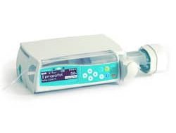
Автоматизированная шприцевая инфузионная система Perfusor Space B Braun состоит из переносного электронного шприцевого насоса и принадлежностей для него. Система предназначена для проведения терапии у взрослых, детей и новорожденных, проведения периодического или непрерывного парентерального или энтерального введения растворов через клинически обусловленные доступы. Эти доступы включают внутривенный, внутриартериальный, подкожный, эпидуральный и энтеральный.
Система применяется для введения медикаментов, предназначенных для инфузионной терапии, включая анестетики, седативные, анальгетики, катехоламины, антикоагулянты и пр.; кровь и компоненты крови; полное парентеральное питание (TPN); жиры; энтеральные смеси, но не ограничивается только ими. Автоматизированная шприцевая инфузионная система Перфузор Спэйс Б. Браун предназначена для применения подготовленным медицинским персоналом в стационарных и амбулаторных лечебных учреждениях, на дому и в санитарном транспорте. Решение о применении данной системы должно приниматься квалифицированным медицинским персоналом на основании ее свойств и технических характеристик.
Производитель Perfusor Space B Braun
Производитель Перфузор Спэйс Б. Браун – B. Braun Melsungen AG, Германия. Представительство в России Б. Браун Медикал ООО, Санкт-Петербург Россия, тел. (812) 320-40-04.
Perfusor Space: Обзор
Ниже представлено описание кнопок и деталей автоматизированной шприцевой инфузионной системы Perfusor Space B Braun.
Вид спереди

Вид сзади

Фиксация шприца

Вытяните и поверните вправо держатель шприца для открытия зеленого осевого фиксатора (см. стрелку). Перед закрытием держателя установите упорную планку цилиндра шприца вертикально в паз слева от осевого фиксатора. Убедитесь в правильном положении шприца. Не касайтесь фиксатора штока при закрытии держателя шприца.
Фиксация универсального зажима

Совместите пазы в верхней части насоса с направляющими универсального зажима и двигайте рамку универсального зажима вперед до щелчка фиксатора. Для отсоединения, нажмите на кнопку извлечения на рамке, опустите транспортную ручку рамки универсального зажима и сдвиньте рамку назад.
Соединение Perfusor Space

До трех насосов (Инфузомат Спэйс B braun или Перфузор Спэйс B braun) с модулем Спэйс Контроль могут стыковаться в единый блок. Остерегайтесь внешнего механического воздействия. Для соединения приборов совместите пазы нижнего насоса с направляющими верхнего и двигайте нижний насос назад до щелчка фиксатора и сопоставления зеленых кнопок друг под другом. Для отсоединения, нажмите на зеленый боковой фиксатор на верхнем насосе и выдвиньте нижний насос.
Фиксация на стойке

Установите зажим на вертикальной стойке и надежно закрутите винтовой фиксатор. Для снятия, открутите фиксатор. Фиксация на горизонтальной стойке: нажмите на рычаг и вращайте рамку в нужную сторону до фиксации в новом положении со щелчком. Для смены положения снова отожмите рычаг.
Управление Perfusor Space
Безопасность пациента
Рекомендации по применению
Список лекарств
До 720 наименований лекарств, включая параметры инфузии и информацию о лекарстве, могут быть сохранены в 15 категориях. Загрузка списка в насос может быть произведена с помощью отдельной компьютерной программы “Drug List Editor Space” (Редактор Списка Лекарств Спэйс).
Список лекарств доступен из Меню Пуск и Меню Специальные функции. Перед началом применения Списка, Пользователь должен убедиться, что Список лекарств в насосе соответствует данной группе пациентов. Наименование Списка лекарств будет отображено на экране насоса.
Существует несколько способов вызова Списка лекарств из Меню для последующего применения. Это возможно как во время инфузии, так и при остановке насоса.
С одной стороны, наименование лекарства со всеми параметрами инфузии может быть выбрано из Списка лекарств. С другой стороны, если скорость, объем и/или время уже были заданы в Главном меню, загружаются наименование лекарства и вновь заданные параметры инфузии. Если расчет дозы уже начат, последующее использование наименования лекарства из списка все равно возможно.
Блок данных
Функция Блок данных защищает прибор от несанкционированного доступа. Четырехзначный код (по умолчанию 9119), который может быть изменен через сервисную программу, активирует эту функцию. Существует три уровня защиты.
Уровень 1
Изменение значений, как и болюсная инфузия недоступны, но можно произвести смену шприца. Возможна навигация по разделам меню и проверка состояния насоса в меню Статус. Пуск, остановка и выключение насоса доступны.
Уровень 2
Этот уровень имеет те же характеристики, что и Уровень 1, но в дополнение к предыдущему, не позволяет произвести смену шприца. Для того, чтобы предотвратить активацию сигнала тревоги «Блок данных», необходимо ввести правильный код в течение 20 секунд после остановки насоса. Смена системы и выключение насоса возможны только после ввода правильного кода.
Уровень 3
Этот уровень позволяет начать и остановить инфузию, а также выключить насос. Код для этого уровня может быть различным для разных лекарств и устанавливается в Списке лекарств. Смена шприца, тем не менее, возможна с использованием кодов, установленных для двух предыдущих уровней.
Обзор различий между уровнями 1, 2 и 3 дан в таблице.

Сигналы и тревоги Perfusor Space B Braun
Перфузор Спэйс б браун оснащен звуковой и визуальной сигнализацией тревоги.

Сигналы неисправности Perfusor Space B Braun
При появлении сигнала неисправности прибора инфузия немедленно прекращается. Нажмите кнопку вкл/выкл для отключения прибора. Затем включите прибор снова. При повторном сигнале тревоги, отсоедините насос от пациента, откройте переднюю дверцу насоса и удалите шприц. Прибор необходимо передать в сервисную службу.
Сигналы предупреждения Perfusor Space B Braun
Сигналы предупреждения подаются за несколько минут (в зависимости от сервисных установок) перед сигналами оповещения. Сигнал предупреждения включает звуковой тон, мигающий желтый индикатор и активирует систему вызова персонала (опция). Текстовое сообщение зависит от причины тревоги. Звуковой тон и система вызова персонала отключаются нажатием кнопки “ОК”. Экран и индикатор остаются в режиме предупреждения вплоть до отключения сигнала оповещения. Во время подачи сигнала предупреждения инфузия не прерывается.
Шприц почти введен
В шприце осталось очень мало жидкости.
Объем почти введен
Введение заданного объема близко к завершению.
Заданное время инфузии скоро истечет.
Батарея почти разряжена.
Объем введен/Время истекло и насос продолжает инфузию в режиме KVO – Открытая вена.
Насос установлен в систему, хотя бы один из приборов в которой несовместим или неисправен. Применение этого прибора в системе не разрешается. Систему необходимо передать для проверки в сервисную службу.
Таймер на экране ведет обратный отсчет оставшегося времени ( в зависимости от сервисной настройки, от 3 до 30 мин). После этого насос подает сигнал оповещения.
Сигналы оповещения Perfusor Space B Braun
Сигналы оповещения приводят к прерыванию инфузии. Подается звуковой сигнал, мигает красный индикатор и активируется система вызова персонала. На экране появляется сообщения «Тревога» и информация о причине сигнала тревоги. Звуковой сигнал и система вызова персонала могут быть отключены кнопкой “ОК”. Коррекция должна быть произведена в соответствие с причиной сигнала тревоги.
В шприце не осталось жидкости. Из-за различий в допусках шприцев разных производителей, незначительное количество раствора в шприце может оставаться. Попытка продолжить инфузию приводит к полному опорожнению шприца и отключению через датчик давления. Выполните смену шприца.
Заданный объем введен. Продолжите инфузию или введите новые параметры.
Заданное время инфузии истекло. Продолжите инфузию или введите новые параметры.
Батарея разряжена. Подключите прибор к сети и/или замените батарею. Сигнал о разрядке батареи длится 3 минуты, после этого насос автоматически отключается.
Время работы в режиме KVO истекло. Продолжите инфузию или введите новые параметры.
Обнаружена окклюзия в системе. Достигнут установленный уровень давления. Насос автоматически снижает скорость введения. Проверьте отсутствие петель и перегибов инфузионной линии, проходимость инфузионного фильтра и в/в катетера. Увеличьте уровень окклюзионного давления, если необходимо. Из-за различия в допусках шприцев разных производителей, тревога по давлению может быть обусловлена высокой силой трения между поршнем и цилиндром.
Шприц установлен неверно
Упорные планки цилиндра и штока установлены неправильно.
Держатель шприца быль открыт во время инфузии. Закройте держатель шприца.
Крышка батарейного отсека удалена
Крышка батарейного отсека установлена неправильно. Переустановите крышку до щелчка.
Внешние помехи препятствуют движению привода. Устраните все внешние помехи.
Параметры калибровки насоса были изменены (например, после обновления программного обеспечения). Выполните калибровку через сервисную программу. Выполняется Сервисной службой.
Была нажата кнопка экстренного извлечения шприца и захваты были разведены вручную. Удалите шприц и обратитесь в Сервисную службу.
Планка штока не зафиксирована
Планка штока шприца не контактирует с датчиком давления насоса. Проверьте систему на наличие отрицательного давления и устраните причину.
Время паузы истекло
Установленное время паузы истекло. Задайте новое время паузы или возобновите предыдущую инфузию.
Батарея не установлена
Использование насоса без батареи невозможно. Отключите прибор и установите батарею.
Данные инфузии и насоса не возможно восстановить. Введите данные инфузии и настройки насоса заново.
Данные инфузии сброшены
Параметры инфузии не возможно восстановить. Введите параметры инфузии заново.
Была попытка остановить или отключить насос без ввода кода. Введите правильный код для соответствующего продолжения инфузии или выключите насос.
Красный индикатор не гаснет до возобновления инфузия или выключения насоса.
Если на экране появляется символ гаечного ключа и/или одновременно мигают желтый, красный и синий индикаторы – насос находится в сервисном режиме и его использование для лечения пациентов запрещено. Насос должен быть проверен сервисной службой.
Сигналы напоминания Perfusor Space B Braun
Сигналы напоминания подаются в двух случаях:
Подсказки о причинах сигналов тревоги
При некорректном вводе параметров, на экране появляются соответствующие подсказки, например «Внимание! Значение скорости превышает допустимое»; «Значение не может быть изменено». Включается звуковая сигнализация. Подсказки исчезают через несколько секунд и их подтверждение не требуется.
Работа от батареи и обслуживание
Перфузор Спэйс оснащен современной NiMH батареей. Время работы насоса с новой батареей составляет 8 часов при скорости инфузии 25 мл/ч. Для оптимальной работы аккумулятора, насос имеет защиту от перегрузки и полной разрядки. Батарея заряжается при включении прибора в сеть. При отключении от сети или в случае падения напряжения, насос автоматически переходит на питание от батареи.
Перед длительным хранением насоса (более 2-х недель без использования), батарея должна быть полностью заряжена, а затем извлечена из насоса. Перед извлечением (сменой) батареи всегда отсоединяйте насос от пациента и отключайте прибор.
Индикатор заряда батареи отображается на экране (низкий, средний, полный заряд). Для получения более детальной информации о состоянии батареи (время работы в часах и минутах) необходимо в меню «Статус» войти в раздел «Батарея».
Самотестирование батареи Perfusor Space B Braun
Если символ батареи мигает во время работы от сети, батарея либо разряжена, либо быстро разряжается. В этом случае насос не должен отключаться от сети. Если необходимо экстренно отключить насос от сети, убедитесь, что остаточный заряд батареи достаточен для применения. Если символ батареи мигает непрерывно (>1ч), батарея должна быть проверена техническим персоналом и замене-на при необходимости.
Оптимальное использование батареи
Факторы, влияющие на срок службы батареи:
Срок службы батареи можно увеличить путем ее регулярной зарядки и разрядки. Для этого насос должен работать от батареи до появления сигнала тревоги о ее разрядке. После этого прибор необходимо подключить к сети минимум на 6 часов. Рекомендуется выполнять данную процедуру один раз в месяц.
Батареи могут взрываться и протекать при вскрытии или сжигании. Соблюдайте правила утилизации!
Обслуживание батареи Perfusor Space B Braun
Для точной регулировки емкости батареи необходимо ее циклическое обслуживание. Насос запрашивает Пользователя о проведении обслуживания батареи каждые 30 дней. В режиме обслуживания батареи определяется возможная потеря емкости (например, из-за старения батареи) и затем емкость и время работы от батареи пересчитываются заново. После длительного хранения или длительной работы без обслуживания батареи, может случиться так, что время подачи предупредительного сигнала больше не будет поддерживаться. В этом случае необходимо проведение обслуживания батареи.
Для инициализации полной разрядки батареи на экране появляется запрос «Обслуживание батареи» и отображается кнопка “ОК”. Для того, чтобы запустить процесс разрядки батареи, нажмите “ОК” и “вверх”. При включении насоса процесс прерывается. Если обслуживание батареи необходимо продолжить, нужно повторно активировать режим обслуживания. После полной разрядки батареи происходит ее полная зарядка. Полное обслуживание батареи длится приблизительно двенадцать часов.
Примите во внимание, что время работы от батареи может быть меньше, если обслуживание батареи не завершено.
Технические характеристики Perfusor Space B Braun
Ниже указаны технические характеристики насоса Perfusor Space B. Braun.
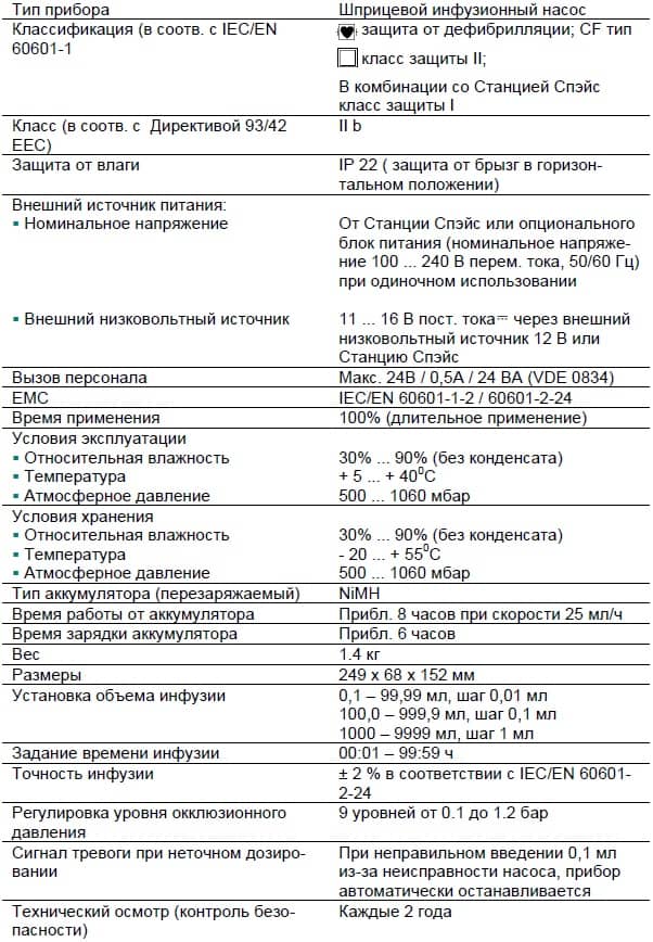
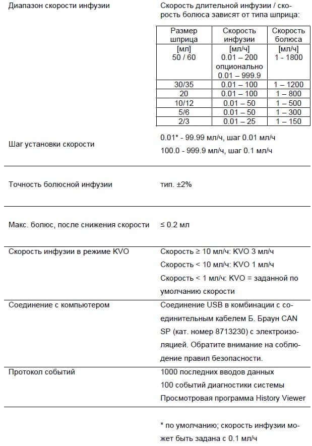
Гарантия Perfusor Space B Braun
Компания Б. Браун предоставляет 24 месяца гарантии, с момента поставки на каждый Перфузор Спэйс (12 месяцев на каждый аккумулятор (Battery Pack SP)). Гарантия предусматривает ремонт или замену отдельных частей, вышедших из строя в результате конструкторских или производственных ошибок, а так же дефектов материала. Срок действия гарантии прекращается в случае модернизации или ремонта, проведенных Пользователем или посторонними лицами.
Гарантия не распространяется на устранение дефектов, вызванных неправильным / неумелым обращением или нормальным износом прибора.
Регулярная проверка Perfusor Space B Braun
Проверяйте чистоту, комплектность, отсутствие повреждений. Используйте прибор только согласно Руководству по применению. При каждом включении проверьте: самотестирование, звуковой сигнал, индикацию работы и сигнализацию.
Уход Perfusor Space B Braun
Очищайте поверхность насоса с использованием мыльного раствора. Не рекомендуется применять распылители в местах контакта с электричеством. Рекомендуется: средство для протирания, например Мелисептол фирмы Б. Браун. После очистки прибор должен высохнуть в течение как минимум одной минуты. Не распыляйте в отверстия прибора. Соблюдайте инструкции по утилизации использованных расходных материалов и уходу за батареями и принадлежностями. Увеличительное стекло передней крышки и экран протирайте мягкой салфеткой. Не используйте Гексакварт.
Принадлежности и каталожные номера Perfusor Space B Braun
Б. Браун Перфузор Спэйс (871 3030)
Станция Спэйс (871 3140)
Станция Спэйс предназначена для установки до четырех насосов.
Верхняя крышка СпэйсКавер стандарт (871 3147)
Верхняя крышка СпэйсКавер комфорт (871 3145)
Верхняя крышка предназначена для установки на Станцию Спэйс. Крышка имеет встроенную ручку для переноски Станции. СпэйсКавер комфорт дополнительно оснащена центральной сигнализацией с блоком управления и сигнальными индикаторами.
Универсальный зажим Спэйс (871 3130)
Предназначен для фиксации до трех насосов Б. Браун Спэйс и одного модуля Спэйс Контроль и их стыковки в единый блок.
Блок питания Спэйс (871 3110A)
Обеспечивает питание от сети для одного насоса или для модуля Спэйс Контроль.
Комби – кабель Спэйс 12 В (871 3133)
Комби – кабель Спэйс позволяет объединить до трех насосов. Все насосы могут быть подключены через блок питания Спэйс или соединительный кабель 12 В.
Перезаряжаемая батарея Спэйс (871 3180)
Интерфейсный кабель CAN Спэйс (871 3230)
Интерфейсный кабель CAN Спэйс требуется для соединения Станции Спэйс / насоса Спэйс с компьютером (для сервисных целей).
Соединительный кабель Спэйс 12 В (871 3231)
Кабель Спэйс для системы вызова персонала (871 3232)
Используйте указанный соединительный кабель для подключения насоса Перфузор Спэйс к системе вызова персонала. Подключение к системе вызова персонала необходимо для выполнения требований VDE 0834.
Оригинальные шприцы Perfusor Space B Braun
Оригинальные линии Perfusor Space B Braun
Скачать инструкцию на Perfusor Space B Braun
Скачать инструкцию и другую документацию на Perfusor Space B Braun можно здесь.
Руководство пользователя ( user manual ) на русском языке Perfusor Space B Braun скачать.
Сервисная инструкция ( service manual ) на английском языке Perfusor Space B Braun скачать.
Источники:
https://medtech30.ru/perfusor-space-b-braun-shpricevoj-nasos/