Функция самодиагностики
В таблице 3 приведены возможные режимы работы ТВ и соответствующая этим режимам индикация на передней панели.
Таблица 3. Индикация режимов работы ТВ
|
Режим работы ТВ |
Индикаторы передней панели |
Примечание |
||
|
Power |
Stand By |
Pic Off/ Connecting/Timer |
||
|
Рабочий (Power On) |
Зеленый |
Выкл. |
Выкл. |
|
|
Дежурный (Standby) |
Выкл. |
Красный |
Выкл. |
|
|
Встроенная диагностика (Self Diagnosis) |
Выкл. |
Красный |
Выкл. |
Мигает в соответствии с таблицей 4 |
|
Ошибка идентификации ЖК панели (Error of panel ID) |
Зеленый |
Выкл. |
Оранжевый |
0,5 с Вкл./0,5 c Выкл. |
|
Включен таймер сна ([REC][Sleep Timer] [Power ON]) |
Красный |
Выкл. |
Оранжевый |
|
|
Включен таймер на выключение ТВ ([Picture Off ][On Timer][REC] [Power On]) |
Красный |
Выкл. |
Зеленый |
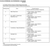
ТВ шасси AZ1-A имеет встроенную систему самодиагностики. Все сбои (ошибки), возникающие во время инициализации ПО шасси, а также в рабочем режиме, фиксируются в регистре ошибок, который можно прочитать и сбросить (очистить) в сервисном режиме (см. описание ниже). Если ошибка фатальная и изображение на экране ТВ отсутствует, то код ошибки отображается периодическими вспышками светодиодного (LED) индикатора дежурного режима (Stand By) на передней панели. На рис. 5 приведена временная диаграмма индикации ошибок, в частности, индикатор делает четыре вспышки с интервалом 3 с, то индицирует ошибку соответствующих плат или ЖК панели (см. таблицу 4).

Рис. 5. Временная диаграмма индикации ошибок
Таблица 4. LED-индикация системы самодиагностики об ошибках и возможные причины
|
Количество вспышек LED -индикатора |
Ошибка |
Действия (последовательная замена узла до устранения) |
|
2 |
Неисправность системы питания (Main Power Error) |
1. Замена платы GD1 (для моделей 22”), G1LS (26”), G2LE (32”), G2HE (40”) 2. Замена главной платы BAA |
|
3 |
Неисправность DC-источников на плате ВАА, звукового тракта или видеосистемы (DC_ALERT1/ Audio Error/ Motion flow Error) |
1. Замена платы BAA 2. Замена платы GD1 (22”), G1LS (26”), G2LE (32”), G2HE (40”) 3. Замена платы T-CON 4. Замена динамических головок |
|
4 |
Неисправность системы отображения (Balancer Error) |
1. Замена платы инвертора питания CCFL 2. Замена ЖК панели 3. Замена платы GD1 (22”), G1LS (26”), G2LE (32”), G2HE (40”) 4. Замена платы BAA |
|
5 |
Ошибка контроллера таймингов T-CON или ошибка идентификации ЖК панели (T-CON Error/ Panel ID NVM Error) |
1. Замена платы T-CON 2. Замена платы BAA 3. Замена кабеля LVDS 4. Замена платы GD1 (22”), G1LS (26”), G2LE (32”), G2HE (40”) |
|
6 |
Ошибка системы подсветки ЖК панели (Backlight Error) |
1. Замена платы инвертора питания CCFL 2. Замена платы GD1 (22”), G1LS (26”), G2LE (32”), G2HE (40”) 3. Замена платы BAA |
|
7 |
Превышен порог температуры (Temp Error) |
1. Замена платы BAA 2. Замена платы GD1 (22”), G1LS (26”), G2LE (32”), G2HE (40”) |
В таблице 4 приведены сообщения системы самодиагностики об ошибках(миганием индикатора Standby) и последовательность замены соответствующих узлов (плат) шасси для устранения этих ошибок (неисправностей).
Сервисный режим
Меню встроенной самодиагностики
Для входа в это сервисное меню переключают ТВ в дежурный режим (Standby) и на штатном ПДУ типа RM-GA019 последовательно нажимают следующие кнопки: <Display> — <5> — <Vol Down> — <Power>.
На экране ТВ должно появиться меню, приведенное на рис. 6.

Рис. 6. Меню встроенной самодиагностики
Для сброса всех счетчиков (регистров) ошибок на ПДУ последовательно нажимают кнопки <8> и <0>. Для сброса времени работы ЖК панели (в нижней строке правая группа цифр — время в часах) последовательно нажимают кнопки <7> и <0>. Чтобы выйти из этого меню, выключают телевизор кнопкой <Off> на ПДУ.
Вход в сервисный режим
Для входа в сервисный режим переключают ТВ в режим Standby и на штатном ПДУ последовательно нажимают следующие кнопки:
< Display> — <5> — <Vol Up> — <Power>.
На экране ТВ должно появиться главное меню сервисного режима, приведенное на рис. 7.

Рис. 7. Главное меню сервисного режима
Для навигации в сервисном меню используют курсорные кнопки «Вверх» и «Вниз», а для выбора соответствующего субменю — центральную курсорную кнопку <+>. Так, на рис. 8 показано субменю Status Information.

Рис. 8. Субменю Status Information
Режим заводских настроек Factory Mode
Для входа в этот режим (рис. 9) телевизор должен быть включен в рабочий режим. На ПДУ последовательно нажимают следующие кнопки:
<Влево> — < Вправо> <Muting> <+> — <Muting> — <Home>.

Рис. 9. Меню режима заводских настроек Factory Mode
Этот режим используется во время заводских регулировок ТВ и настроек после его ремонта. Так, например, после замены главной платы или ЖК панели требуется ввести ID-код ЖК панели. Для этого курсорными кнопками <Вверх>, <Вниз> на ПДУ выбирают строку Panel_ID, а затем копками <Влево>, <Вправо> выбирают код, соответствующий установленному типу ЖК панели (см таблицу 5).
Таблица 5. ID-коды ЖК панелей
|
Модель ТВ |
ID -код |
Бренд |
Тип |
|
KLV-32BX300, KLV-32BX301 |
F SS32 |
SLCD |
LTY320HN02-001 |
|
KLV-32BX400, KLV-32BX400 |
W-LG32 |
LCD |
LC320WXN-SCB1 |
|
KLV-32BX400, KLV-32BX401 |
F CM32 |
CMI |
V315H3L01 |
|
KLV-40BX400, KLV-40BX401 |
F SS40 |
SLCD |
LTU400HM02-A01 |
Для выхода из режима Factory Mode без выключения ТВ нажимают кнопку Return на ПДУ.
По умолчанию регулировки цветовой температуры в ТВ выполнены для оптимального просмотра программ. При необходимости (или при желании) их можно скорректировать в режиме Factory Mode. Для этого в меню выбирают строку Color Temp (рис. 10) и нажимают кнопку <+> на ПДУ.

Рис. 10. Выбор субменю регулировки цветовой температуры Color Temp
На экране должно появиться субменю регулировки цветовой температуры, приведенное на рис. 11.

Рис. 11. Субменю регулировки цветовой температуры
Вначале в соответствующей строке выбирают тип цветовой температуры: Cool, Neutral, Warm1, или Warm2. Затем переходят к параметрам R(G, B) Gain и R(G, B) Offset и регулируют их значения. Для сохранения новых значений цветовой температуры выбирают строку Data Backup и нажимают кнопку <+>.
После регулировки одного типа цветовой температуры выбирают другой тип и выполняют регулировку в вышеуказанной последовательности.
Для выхода из режима заводских регулировок нажимают кнопку Power.
Литература
1. Sony Corporation. Service manual AZ1-A Chassis. KLV-22BX300, KLV-26BX300, KLV-32BX300, KLV-40BX400. 2010.
2. Sony Corporation. Service manual AZ1-A(5-2) Chassis. Models KLV-22BX300 RUSS, KLV-26BX300 RUSS, KLV-32BX300 RUSS, KLV-40BX400 RUSS. 2010.
Автор: Николай Елагин (г. Зеленоград)
Источник: Ремонт и сервис
Good Sunday morning everyone.
I have the TV listed above in hand which was given to me for free after a lightning strike took it out along with several other items in a friends house. Upon plugging it in and pressing the power button, the startup tone plays followed by an immediate shutdown with the 6 blink error. I downloaded the service manual and 6 blinks = backlight issue. This seems logical since the backlights don’t even flash when the TV attempts to power up.
Next step, removed the back and checked voltages. Main board is sending the POW-ON and BL-ON signals. Flashlight test shows the Sony Logo when It tries to start. Power Supply has 12V present but no 24V.
Removed supply from TV to bench test. Fed 3V from the standby pin into POW-ON and BL-ON (I had previously confirmed the main board was sending these signals so I assumed I would get the same result). Confirmed that the 24V rail does not come up even for a second. 12V rail is steady at 12.14V actual output. Main filter cap is steady at 392V when POW-ON is applied and is 165V without POW-ON.
I’ve attached pictures of just the power supply since I already have the problem narrowed down. I’m quite efficient at component level repair but haven’t worked on this particular board. Replacements are scarce. I do see one person on Ebay offering repair service for $65 but I’d prefer to do it myself if possible. As always, any opinions are greatly appreciated.
Thanks in advance,
Aaron
![]()
-
#1
Main 1-893-413-31 (173503931)
MT5561TUHT
Поступил в ремонт, при включении, три раза заставка Sony и уходит в защиту с ошибкой 6 (моргание светодиода красным с интервалом в одну секунду). По словам заказчика, супруга выдернул из розетки работающий телевизор.
Проверил питания 3,3V, 1,2V, 5.0V всё наместе. Вскрыл матрицу, подключил телевизор {фронтальная подсветка), верхний и нижний ряд светодиодов моргает кратковременно,средний горит (подсветка заставки Sony), повреждённых светодиодов нет. Дальше подозрение на ШИМ RT8292AH или сам драйвер BD9397EFV.
Подскажите пожалуйста куда копнуть дальше?
Просто на дружественном форуме, пользователя ткнули носом в Services manuale по данной ошибке где явно связано с подсветкой.
Может ПО слетела,тогда как прошить, через USB, если я даже.в меню попасть не могу,. Пробовал отключать подсветку, ошибка таже 6….
-

93,1 КБ
Просмотры: 18
![]()

![]()
-
#4
А почему Вы решили, что она поможет?, я ведь описал суть проблемы в первом посте, на контрольной точке подсвктки при старте телевизора появляется напряжение 39V и дальше сваливается в ошибку.
По факту при запуске телевизора без T-con подсветка должна вся светиться и затем уйти в защиту с ошибкой 5,у меня же нет запуска Backlight норм.
Что дальше делать, менять сам драйвер BD9397EFV?
Последнее редактирование: 9/1/22


-
#5
Матрас скинь и посмотри какая лампа сдохла
вот для примера тоже самое и моргает и свистит. Это же сони ))) Только колхозить не надо как в видео )
![]()
-
#6
Матрас скинь и посмотри какая лампа сдохла
вот для примера тоже самое и моргает и свистит. Это же сони ))) Только колхозить не надо как в видео )
Вы , что совсем ничего не читаете? Писал ,что разбирал матрицу до планок подсветки , все диоды целы, пробоя на подложку нет… Не свистит. Я тоже умею тыкать в видео и всякие прибамбасы… Нет конкретики уважаемый , или Вы не знаете ничего…

-
#7
сони капризные к подсветке и к матрицам,без матрицы тоже ошибка будет ,ваша ошибка от том что с подсветкой проблемы,рвутся по току
![]()
-
#8
сони капризные к подсветке и к матрицам,без матрицы тоже ошибка будет ,ваша ошибка от том что с подсветкой проблемы,рвутся по току
Ну таки да , если все диоды целы , то дальше куда копать. T-Con Error — ошибка 5 , при отключении матрицы .
Что менять , RT8292AH , или драйвер?
-
#9
Ну таки да , если все диоды целы , то дальше куда копать. T-Con Error — ошибка 5 , при отключении матрицы .
Что менять , RT8292AH , или драйвер?
Если все диоды целы, но подсажены, то будет ошибка 6. Причём относительно и не плохо светить будут, разницу увидите когда новые поставите. ТВ не занимаюсь от слова совсем, но родителям когда-то покупал 2 таких ТВ и на них с периодичностью в пол года ошибка 6. Замена подсветки решила проблему на обоих. Все диоды были живые, менял комплект 3 планки.
![]()
-
#10
ТВ не занимаюсь от слова совсем, но родителям когда-то покупал 2 таких ТВ и на них с периодичностью в пол года ошибка 6. Замена подсветки решила проблему на обоих. Все диоды были живые, менял комплект 3 планки.
Так я тоже по промышленной электронике в основном . Телевизору 7 лет , что по нынешним меркам — пенсионер , хотя мог и дальше работать при правильной эксплуатации , но это лирика . Стоимость драйвера и ШИМ контроллера в «рубль» обходится , планки , как я понял на алике заказывать придётся…
-
#11
Так я тоже по промышленной электронике в основном . Телевизору 7 лет , что по нынешним меркам — пенсионер , хотя мог и дальше работать при правильной эксплуатации , но это лирика . Стоимость драйвера и ШИМ контроллера в «рубль» обходится , планки ,
Так я тоже по промышленной электронике в основном . Телевизору 7 лет , что по нынешним меркам — пенсионер , хотя мог и дальше работать при правильной эксплуатации , но это лирика . Стоимость драйвера и ШИМ контроллера в «рубль» обходится , планки , как я понял на алике заказывать придётся…
Планки брал на алике, но там магазин с экспресс доставкой. Около 1000р за 3 шт. вышло. Доставили за 3-4 дня. Нашёл в истории
купить чтобы получить доступ к скрытому контенту.
8 ODPOW. 8
profile.country.PL.title

Użytkownik
sierpnia 2017
Witaj
jak znajdziesz gdzieś odpowiedz nt. błędów menu serwisowego to daj znać proszę. W menu mojego telewizora też mam dziwny wpis ale nikt nie chce zdradzić czego dotyczy. Ani Sony ani serwis (Radom).
profile.country.PL.title

Moderator
sierpnia 2017
Witaj,
Skonsultujemy Twoje pytanie z pomocą techniczną. Damy znać jak tylko pojawi się odpowiedź.
Pozdrawiam,
Barbara_K
profile.country.PL.title

Użytkownik
sierpnia 2017
PODEPNĘ SIĘ POD TEMAT,MAM TEN SAM BŁĄD,CHYBA CHODZI O PODŚWIETLENIE MATRYCY.TV KD-65 XD 8505.
profile.country.PL.title
Moderator
sierpnia 2017
Niestety nie będziemy mieć informacji dotyczących błędów w menu serwisowym. Powodem tej sytuacji jest możliwość utraty gwarancji po samodzielnym otworzeniu tego menu (procedura zarezerwowana jest wyłącznie dla autoryzowanych centrów serwisowych). Zalecana jest jednak weryfikacja telewizora przez centrum serwisowe. Zgłoszenie można wysłać poprzez poniższy formularz:
http://services.sony.pl/supportmvc/pl/Repair/BookRepairForm
Pozdrawiam,
Barbara_K
profile.country.PL.title

Doradca
sierpnia 2017
Szanowni Państwo  @Barbara_K @74adam @kosa16051971 jak na mój gust to żaden z tych modeli nie ma funkcji tylnego podświetlenia BACKLIGHT co w związku z tym daje w kolumnie BACKLIGHT — ERROR.
profile.country.PL.title
Użytkownik
sierpnia 2017
TO MNIE KOLEGO USPOKOIŁEŚ,WIELKIE DZIĘKI.
profile.country.PL.title
Użytkownik
sierpnia 2017
ALE Z DRUGIEJ STRONY MOŻE BYĆ TAK,ŻE DOTYCZY TO OGÓLNIE PROBLEMU Z PODŚWIETLENIEM MATRYCY,NIE WAŻNE JAKI TO JEST MODEL.
profile.country.PL.title
Użytkownik
sierpnia 2017
NAWET W SŁOWNIKU PODŚWIETLENIE TO PO PORZETŁUMACZENIU BACKLIGHT.

LED BLINKING ERROR CODE AND DESCRIPTION
SELF DIAGNOSIS FUNCTION
If an error occurs, the STANDBY LED will
automatically begin to flash.
The number of times the LED flashes translates to a probable source of the
problem.
A definition of the STANDBY LED flash indicators is listed in the instruction
manual for the user’s knowledge and reference.
If an error symptom cannot be reproduced, the remote commander can be used to
review the failure occurrence data stored in memory to reveal past problems and how often these problems occur.
DIAGNOSTIC TEST INDICATORS
When an error occurs, the STANDBY LED will flash a set number of times to
indicate the possible cause of the problem. If there is more than one error,
the LED will identify the first of the problem areas. Result for all of the
following diagnostic items are displayed on screen. If the screen displays a
“0”, no error has occurred .
LED BLINKING CODES
|
Number |
Monitoring
|
Diagnostic
|
|
2 times |
DC_DET |
Main |
|
6 times |
PANEL_DET |
Panel |
|
7 times |
TEMPERATURE |
monitor |
|
8 times |
AUDIO |
Audio |
|
9 times |
HFR |
High |
|
10 |
DEF |
DEF |
|
11 |
NVM |
EEPROM |
|
12 |
I2C |
VCT I2C |
|
13 |
BALANCER |
Panel |
|
14 |
HDMI |
HDCP |
|
15 |
TUNER |
If |
|
16 |
I2C CH1 |
I2C |
|
17 |
I2C CH0 |
I2C CH0 |
|
18 |
DIGITAL |
No |
|
19 |
USB |
USB |
|
20 |
CI |
CI |
|
21 |
VCT |
No |
|
22 times |
MSP |
MSP3410G |
SELF-DIAGNOSTIC SCREEN DISPLAY
For errors with symptoms such as “power sometimes shuts off” or “screen
sometimes goes out” that cannot be confirmed, it is possible to bring up past occurrences of failure for confirmation on the screen:
To Bring Up Screen Test
In standby mode, press buttons on the remote commander sequentially in rapid
succession as shown below:
INFORMATION >NUMBER BUTTON 5 > VOLUME — > TV STANDBY
Since the diagnostic results displayed on the
screen are not automatically cleared, always check the self-diagnostic screen After you have completed the repairs, clear the result display to “0”.
Clearing the result display
To clear the result display to “0”, press button on the remote commander
sequentially as shown below when the diagnostic screen is being displayed.
<Delection of Error Count and Error History>
Press “8” button , Press “0” button
<Delection of Panel Operation Time>
Press “7” button , Press “0” button
Quitting Self-diagnostic screen
To quit the entire self-diagnostic screen, turn off the power switch on the
remote commander or the main unit.
LED BLINKING DESCRIPTION
RED 2 times blink
DC_DET
# This indicates DC_DET of Power Board.
# 12V line on Power Board.
# MOUTON micro (on BGC board) Pin6 detects POWER_DET and shuts down chassis
power to standby status.
MOUTON micro Pin6 Normal condition: 1.3V — 2.5V
Error case: lower than 1.3V or higher than 2.5V
Replace Power Board.
RED 6 times blink
Backlight Error
# This indicates panel power circuit error such as inverter.
# MOUTON micro (on BGC board) Pin40 detects PANEL_DET and shuts down chassis
power to standby status.
MOUTON micro Pin40 Normal condition: High / Error case: Low (lower than 0.8V)
Replace Panel or Power/Inverter Board .
RED 7 times blink
Temp Error
# This indicates high temperature inside chassis. IC5507 on BGC board is
monitoring temperature. IC5507 is controlled by MOUTON micro.
# When it happens:
Check chassis environment.
Check around IC5507 and replace BGC board if temperature monitoring circuit has
problem.
Check panel.
RED 8 times blink
Audio Error
#This indicates Audio Error (Protection).
# It happens:
IC8200 on BGC board, Audio Amp detects over current, thermal shut down and/or
low voltage of itself.
DC voltage detected for audio line.
MOUTON micro Pin5 Normal condition: High / Error case: Low
# Check UNREG15V at CN6401 Pin4 and Pin5 on BGC board . And F3401 on BGC board
has 13V or not.
# Check above and replace BGC board.
RED 9 times blink
HFR Error
# This indicates HFR Communication error.
# [ HFR Communication error ]
Mouton (IC5505) micro (on BGC board) is communicating with T-con board.
# Check above and replace BGC board or LVDS harness (between BGC board and
T-con board.
RED 10 times blink
DEF Error
# This indicates DEF communication error.
# [ communication error ]
# TVM micro (on BGC board) is communicating with EMMA3SL (on BGC board).
#Check above and replace BGC board .
RED 11 times blink
NVM Error
# This indicates MOUTON NVM communication error.
# MOUTON micro (on BGC board) is communicating with NVM (on BGC board) .
# Check above and replace BGC board.
RED 12 times blink
I2C Error
# This indicates I2C communication error.
# VCTP micro (on BGC board) is communicating with each devices (on BGC board).
# Check above and replace BGC board .
RED 13 times blink
Balancer Error
# This indicates panel power circuit error such as inverter.
# MOUTON micro (on BGC board) Pin81 detects PANEL_DET and shuts down chassis power
to Standby status.
MOUTON micro Pin40 Normal condition: High / Error case: Mid (0.85 — 2.65V)
# Replace Panel or Power/Inverter board.
RED 14 times blink
HDMI Error
# This indicates HDCP error.
# HDMI setting trouble matter on BGC board.
# Check above and replace BGC board.
RED 15 times blink
Tuner Error
# This indicates Tuner error.
# VCTP and EMMA3SL micro (on BGC board) is communicating with Tuner (TU2200) on
BGC board.
# Check above and replace BGC board.
RED 16 times blink
I2C-CH1 Error
# This indicates I2C communication error.
# MOUTON micro (on BGC board) is communicating with Audio processor (IC3201) on
BGC board.
# Check above and replace BGC board.
RED 17 times blink
I2C-CH0 Error
# This indicates I2C communication error.
# MOUTON micro (on BGC board) is communicating with Real time clock (IC5502) on
BGC board.
# Check above and replace BGC board.
RED 18 times blink
Digital modulator Error
# This indicates Tuner error.
# EMMA3SL micro is communicating with inside of the Tuner (TU2200) on BGC
board.
# Check above and replace BGC board.
RED 19 times blink
USB Error
# This indicates USB error.
# EMMA3SL micro found out USB over current detection on BGC board.
# Check above and replace BGC board.
RED 21 times blink
VCTP Error
# This indicates VCTP error.
# VCTP micro (IC4701) does not work normaly.
# Check above and replace BGC board.
Sony Trinitron Error Codes 6 Blinks
Get free help, tips & support from top experts on sony trinitron fault codes related issues..sony
error codes)usually indicates a high voltage shutdown(t.v has Sony Trinitron Problems — Red light
blinks 6 times The TV will not turn on. Sony kdl 46ex523 blinks twice 2 times wont turn on fix
repair Led TV Sony Bravia KDL.
Sony Trinitron – 6 blink error code (Won‘t turn on) –
YouTube – Dec 03, 2011 · This board is out of a Sony
Trinitron Model KV-40XBR800. It was getting.
Sony Trinitron (Flat Panel) TV!, 1976 Sony Trinitron 17″ CRT Color TV, Sony Trinitron CRT
Repair Sony Trinitron — 6 blink error code (Won’t turn on). Trend to find everything: SONY
TELEVISION BLINKING CODES – May 27, 2011 · Many of the later Dec 03, 2011 · This
board is out of a Sony Trinitron Model KV-40XBR800. It was getting the 6-blink error code and
TV would not turn. Sony Trinitron CTV _ KV-29M** _ Service Mode _ URC set-up
codes_LED Blinking codes. blinking codes _ Universal Remote Control Set-up codes to check
with Sony Use 1 and 4 to select the adjustment item, use 3 and 6 to adjust, write with When an
error occurs, the STANDBY indicator will flash a set number.
Sony Trinitron Error Codes 6 Blinks
>>>CLICK HERE<<<
a flashing red light (6 times flashing before pause — error code) and it
won’t turn on either. I can’t reset and don‘t know the code for it HELP
SOMEONE PLEASE //// Red light blinking 6 times after pause of 2 secs
HELP! i have a sony trinitron tv won’t turn it because my son was
playing on his ps3 then it turned off it. 03.12.2011 · This board is out of
a Sony Trinitron Model KV-40XBR800. It was getting the 6-blink error
code and TV would not turn. Two driver chips were …
during the first click, but then does not blink an error code after the
second. I have a tv Sony Trinitron XBR (KV-34XBR800). The tv does
not turn on, the LED red light flashes 7 times most of the time, it flashed
6 times repeatedly in one occasion. To my surprise the set came on, but I
still get a 4 blink code followed by 1. What Does A 6 Blinking Sony
Trinitron Error Code Mean. (Posted by If The Light Blinks 4 X‘s, 5 X‘s,
6 X‘s, And 7 X‘s How Much Will It Cost To Fix? (Posted. San Diego,