А чем проигрыш арбитража отличается от коллизии в CAN?
Хоть это и не относится к вопросу ТС… давайте разберемся)
Если адреса узлов разные и передача стартует одновременно, то узел с меньшим адресом выигрывает арбитраж и продолжает передавать.
Проигравший не просто отвалится, он еще и корректно примет эту посылку.
Но это только в поле адреса узла. Если при передаче данных и служебных полей будет обнаружен доминант при передаче рецессива, то
узел не перейдет в режим слушателя, а начнет активно действовать:
1) увеличит счетчик ошибок передачи (+8?);
2) если счетчик меньше определенного значения (<127?), то выставит несколько доминантов (6?) на шине — мол, ошибка (активная). Все кто принимал увидят эту ошибку и увеличат свои счетчики ошибок приема;
3) если счетчик больше определенного числа, то выставит несколько рецессивов (6?) — тоже ошибка, только пассивная;
4) если счетчик переполнился (255), то наступает bus-off на сколько-то idle-циклов шины (13?).
5) если счетчик не переполнился, то будет повторная передача (если она включена, зависит от протокола, настроек контроллера и т.п.). При этом bus-off гарантируется.
Итого: два одинаковых id узла на шине страшное зло! а не просто потеря арбитража.
PS. В деталях могу напутать, но общий смысл такой.
What are Error Active, Error Passive, and Bus off of CAN Bus?
Just to give a little background to the answer:
In order to prevent malfunctioning nodes from disturbing, or even blocking, an entire system, the CAN protocol implements a sophisticated fault confinement mechanism. The CAN protocol is intended to be orthogonal, i.e. all nodes address faults in the same manner. Fault confinement is provided where each node constantly monitors its performance with regard to successful and unsuccessful message transactions. A Transmit Error Counter (TEC) and a Receive Error Counter (REC) create a metric for communication quality based on historic performance. Each node will act on its own bus status based on its individual history. As a result, a graceful degradation allows a node to disconnect itself from the bus i.e. stop transmitting. This means that a permanently faulty device will cease to be active on the bus (go into Bus Off state), but communications between other nodes can
continue unhindered. If the bus media is severed, shorted or suffers from some other failure mode the ability to continue communications is dependent upon the condition and the physical interface used.
Fault confinement is a checking mechanism that makes it possible to distinguish between short disturbances (e.g. switching noise from a nearby power cable couples into the transmission media) and permanent failures (e.g. a node is malfunctioning and disturbs the bus).
Manipulation of the error counters is asymmetric. On a successful transmission, or reception, of a message, the respective error counter is decremented if it had not been at zero. In the case of a transmit or receive error the counters are incremented, but by a value greater than the value they would be decrement by following a successful message transaction.
If a node detects a local error condition (e.g. due to local conducted noise, application software, etc.), its resulting error flag (primary error flag) will subsequently cause all other nodes to respond with an error flag too (secondary error flags). It is important that a distinction is made between the nodes that detected an error first and the nodes which responded to the primary error flag. If a node transmits an active error frame, and it monitors a dominant bit after the sixth bit of its error flag, it considers itself as the node that has detected the error first. In the case where a node detects errors first too
often, it is regarded as malfunctioning, and its impact to the network has to be limited. Therefore, a node can be in one of three possible error states:
Error active
Both of its error counters are less than 128. It takes part fully in bus communication and signals an error by transmission of an active error frame.This consists of sequence of 6 dominant bits followed by 8 recessive bits, all other nodes respond with the appropriate error flag, in response to the violation of the bit stuffing rule.
Error passive
A node goes into error passive state if at least one of its error counters is greater than 127. It still takes part in bus activities, but it sends a passive error frame only, on errors. Furthermore, an error passive node has to wait an additional time (Suspend Transmission Field, 8 recessive bits after Intermission Field) after transmission of a message, before it can initiate a new data transfer. The primary passive error flag consists of 6 passive bits and thus is “transparent” on the bus and will not “jam” communications.
Bus Off
If the Transmit Error Counter of a CAN controller exceeds 255, it goes into the bus off state. It is disconnected from the bus (using internal logic) and does not take part in bus activities anymore. In order to reconnect the protocol controller, a so-called Bus Off recovery sequence has to be executed. This usually involves the re-initialization and configuration of the CAN controller by the host system, after which it will wait for 128 * 11 recessive bit times before it commences communication.
-
When a receiver detects an error, the REC will be increased by 1, except when the detected error was a Bit Error during the sending of an Active error Flag or an Overload Flag.
-
When a receiver detects a dominant bit as the first bit after sending an Error Flag, the REC will be increased by 8.
-
When a transmitter sends an Error Flag, the TEC is increased by 8. Exception 1: If the transmitter is Error Passive and detects an ACK Error because of not detecting a dominant ACK and does not detect a dominant bit while sending its Passive Error Flag. Exception 2: If the transmitter sends an Error Flag because a Stuff Error occurred during arbitration, and should have been recessive, and has been sent as recessive but monitored as dominant.
-
If the transmitter detects a Bit Error while sending an Active Error Flag or an Overload Frame, the TEC is increased by 8.
-
If a receiver detects a Bit Error while sending an Active Error Flag or an Overload Flag, the REC is increased by 8.
-
Any node tolerates up to 7 consecutive dominant bits after sending an Active Error Flag, Passive Error Flag or Overload Flag. After detecting the fourteenth consecutive dominant bit (in case of an Active Error Flag or an Overload Flag) or after detecting the eighth consecutive dominant bit following a Passive Error Flag, and after each sequence of additional eight consecutive dominant bits, ever y transmitter increases its TEC by 8 and every receiver increases its REC by 8.
-
After successful transmission of a frame (getting ACK and no error until EOF is finished), the TEC is decreased by 1 unless it was already 0.
-
After the successful reception of a frame (reception without error up to the ACK Slot and the successful sending of the ACK bit), the REC is decreased by 1, if it was between 1 and 127. If the REC was 0, it stays 0, and if it was greater than 127, then it will be set to a value between 119 and 127.
-
A node is Error Passive when the TEC equals or exceeds 128, or when the REC equals or exceeds 128. An error condition letting a node become Error Passive causes the node to send an Active Error Flag.
-
A node is Bus Off when the TEC is greater than or equal to 256.
-
An Error Passive node becomes Error Active again when both the TEC and the REC are less than or equal to 127.
-
A node which is Bus Off is permitted to become Error Active (no longer Bus Off) with its error counters both set to 0 after 128 occurrence of 11 consecutive recessive bits have been monitored on the bus.

Need a practical intro to CAN bus errors?
In this tutorial you’ll learn about the basics of CAN error handling, the 5 CAN bus error types, the CAN
error frame and CAN node error states.
To get practical, we’ll also generate & record CAN errors in 6 experiments.
In this article
- What are CAN bus errors?
- The CAN error frame
- 5 CAN error types
- States & error counters
- 6 practical experiments
- LIN bus errors
- CAN error logging use cases
- FAQ

What are CAN bus errors?
As explained in our simple intro
to CAN
bus, the Controller Area Network is today the de facto standard across automotives and industrial
automation
systems.
A core benefit is the robustness of CAN, making it ideal for safety critical
applications.
Here, it is worth noting:
Error handling is vital to the robustness of CAN.
CAN bus errors can occur for several reasons — faulty cables, noise, incorrect termination, malfunctioning
CAN nodes etc. Identifying, classifying and resolving such CAN errors is key to ensuring the continued
performance of the overall CAN system.
In particular, error handling identifies and rejects erroneous messages, enabling a sender to
re-transmit the message. Further, the process helps identify and disconnect CAN nodes that
consistently transmit erroneous messages.

How does CAN error handling work?
Error handling is a built-in part of the CAN standard and every CAN controller. In other words, every
CAN node handles fault identification and confinement identically. Below we’ve made a simple illustrative example:

- CAN node 1 transmits a message onto the CAN bus — and reads every bit it sends
- In doing so, it discovers that one bit that was sent dominant was read recessive
- This is a ‘Bit Error’ and node 1 raises an Active Error Flag to inform other nodes
- In practice, this means that node 1 sends a sequence of 6 dominant bits onto the bus
- In turn, the 6 dominant bits are seen as a ‘Bit Stuffing Error’ by other nodes
- In response, nodes 2 and 3 simultaneously raise an Active Error Flag
- This sequence of raised error flags comprise part of a ‘CAN error frame’
- CAN node 1, the transmitter, increases its ‘Transmit Error Counter’ (TEC) by 8
- CAN nodes 2 and 3 increase their ‘Receive Error Counter’ (REC) by 1
- CAN node 1 automatically re-transmits the message — and now succeeds
- As a result, node 1 reduces its TEC by 1 and nodes 2 and 3 reduce their REC by 1
The example references a number of concepts that we will detail shortly: Error frames, error
types, counters and states.
The CAN bus error frame
In the illustrative example, the CAN nodes ‘raise Active Error Flags’, thus creating an ‘error frame’ in
response to detecting a CAN error.
To understand how this works, let us first look at a «normal» CAN frame (without errors):

CAN bus bit stuffing
Notice that we highlighted ‘bit stuffing’ across the CAN frame.
Bit stuffing is a subtle, but vital part of the CAN standard. Basically it states that whenever a CAN node
sends five bits of the same logic level (dominant or recessive), it must send one bit of the opposite level.
This extra bit is automatically removed by the receiving CAN nodes. This process helps ensure continuous
synchronisation of the network.
As per the previous example, when CAN node 1 detects an error during the transmission of a CAN message, it
immediately transmits a sequence of 6 bits of the same logic level — also referred to as raising an Active
Error Flag.
If we measure the transmission of a CAN frame via an oscilloscope and digitize the result, we can also
see the stuff bits in practice (see the red timestamp marks):
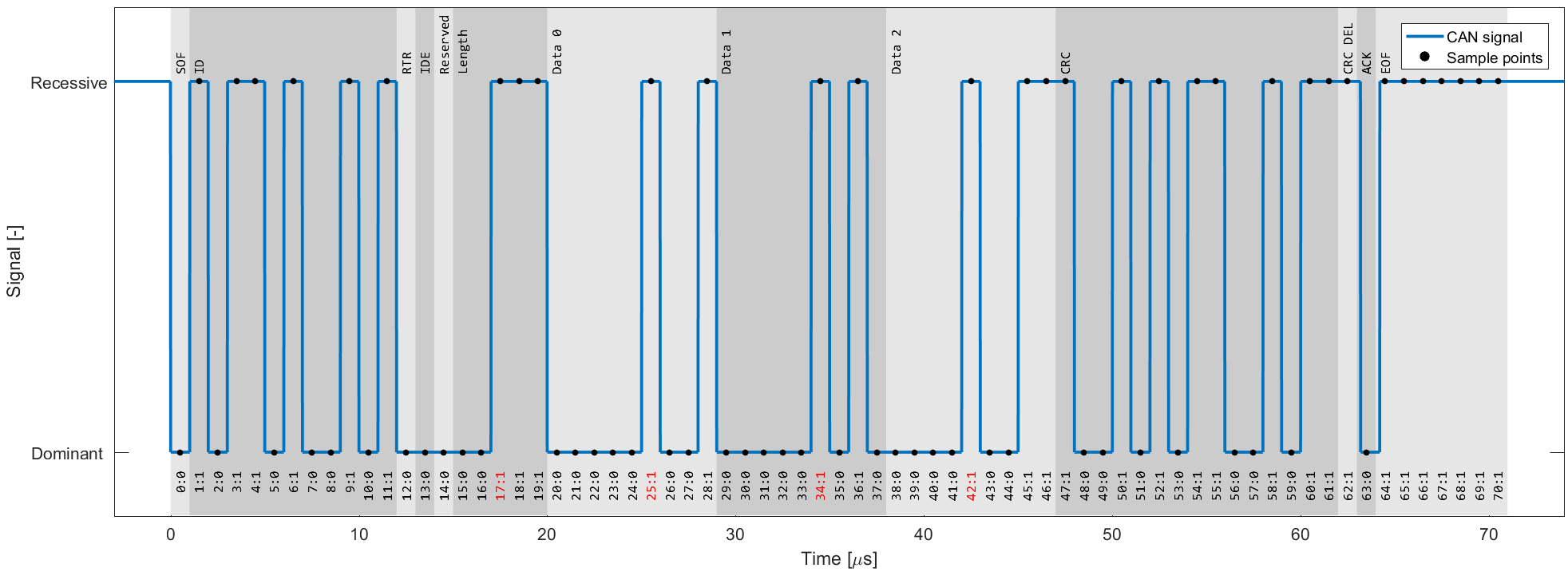


Active Error Flags
As we just learned, such a sequence is a violation of the bit stuffing rule — aka a ‘Bit Stuffing Error’.
Further, this error is visible to all CAN nodes on the network (in contrast to the ‘Bit Error’ that resulted
in this error flag being raised). Thus, the raising of error flags can be seen as a way of
«globalizing» the discovery of an error, ensuring that every CAN node is informed.
Note that the other CAN nodes will see the Active Error Flag as a Bit Stuffing Error. In
response they also raise an Active Error Flag.
As we’ll explain shortly, it is important to distinguish between the error flags. In particular, the first
error flag
(from the ‘discovering’ node) is often referred to as a ‘primary’ Active Error Flag, while
the error flags of
subsequent ‘reacting’ nodes are referred to as the ‘secondary’ Active Error Flag(s).
3 CAN error frame examples
Let’s look at three example scenarios:
Example 1: 6 bits of error flags
Here, all CAN nodes simultaneously discover that an error exists in a CAN message and raise their error
flags at the same time.
The result is that the error flags all overlap and the total sequence of dominant
bits lasts for 6 bits in total. All CAN nodes will in this case consider themselves the ‘discovering’ CAN
nodes.
This type of simultaneous discovery is less common in practice. However, it could e.g. happen as a
result of Form
Errors (such as a CRC delimiter being dominant instead of recessive), or if a CAN transmitter
experiences a bit error during the writing of a CRC field.


Example 2: 12 bits of error flags
Here, CAN node 1 transmits a dominant bit, but reads it as recessive — meaning that it discovers a Bit Error.
It immediately transmits a sequence of 6 dominant bits.
The other nodes only discover the Bit Stuffing Error
after the full 6 bits have been read, after which they simultaneously raise their error flags, resulting in
a subsequent sequence of 6 dominant bits — i.e. 12 in total.
Example 3: 9 bits of error flags
Here, CAN node 1 has already transmitted a sequence of 3 dominant bits when it discovers a Bit Error and
begins sending 6 dominant bits.
Once halfway through the primary Active Error Flag, nodes 2 and 3 recognize
the Bit Stuffing Error (due to the 3 initial dominant bits being followed by another 3 dominant bits) and
they begin raising their error flags. The result is that the sequence of dominant bits from error flags
becomes 9 bit long.

The above logic of raising error flags is reflected in what we call an ‘active’ CAN error frame.

Note in particular how the secondary error flags raised by various nodes overlap each other — and how the
primary and secondary flags may overlap as well. The result is that the dominant bit sequence from raised
error
flags may be 6 to 12 bits long.
This sequence is always terminated by a sequence of 8 recessive bits, marking the end of the error frame.
In practice, the active error frame may «begin» at different places in the erroneous CAN frame, depending on
when the
error is discovered. The result, however, will be the same: All nodes discard the erroneous CAN frame and
the
transmitting node can attempt to re-transmit the failed message.
Passive Error Flags
If a CAN node has moved from its default ‘active’ state to a ‘passive’ state (more on this shortly), it will only be
able to raise so-called ‘Passive Error Flags’. A Passive Error Flag is a sequence of 6 recessive bits as seen below.
In this case it’s relevant to distinguish between a Passive Error Flag raised by a transmitting node and a receiving
node.

Example 4: Transmitter is Error Passive
As shown in the illustration (Example 4), if a transmitter (such as CAN node 1 in our example) raises a
Passive Error Flag (e.g. in response to a Bit Error), this will correspond to a consecutive sequence of 6
recessive bits.
This is in turn detected as a Bit Stuffing Error by all CAN nodes. Assuming the other CAN
nodes are still in their Error Active state, they will raise Active Error Flags of 6 dominant bits. In other
words, a passive transmitter can still «communicate» that a CAN frame is erroneous.
Example 5: Receiver is Error Passive
In contrast, if a receiver raises a Passive Error Flag this is in practice «invisible» to all other CAN nodes
on the bus (as any dominant bits win over the sequence of recessive bits) — see also Example 5.
Effectively,
this means that an Error Passive receiver no longer has the ability to destroy frames transmitted by
other CAN nodes.

CAN error types
Next, let us look at what errors may cause CAN nodes to raise error flags.
The CAN bus protocol specifies 5 CAN error types:
- Bit Error [Transmitter]
- Bit Stuffing Error [Receiver]
- Form Error [Receiver]
- ACK Error (Acknowledgement) [Transmitter]
- CRC Error (Cyclic Redundancy Check) [Receiver]
We’ve already looked at Bit Errors and Bit Stuffing Errors briefly, both of which are evaluated at the bit
level. The remaining three CAN error types are evaluated at the message level.
Below we detail each error type:


#1 Bit Error
Every CAN node on the CAN bus will monitor the signal level at any given time — which means that a
transmitting CAN node also «reads back» every bit it transmits. If the transmitter reads a different data
bit level vs. what it transmitted, the transmitter detects this as a Bit Error.
If a bit mismatch occurs during the arbitration process (i.e. when sending the CAN ID), it is not
interpreted as a Bit Error. Similarly, a mismatch in the acknowledgement slot (ACK field) does not cause
a Bit Error as the ACK field specifically requires a recessive bit from the transmitter to be
overwritten by a dominant bit from a receiver.

#2 Bit Stuffing Error
As explained, bit stuffing is part of the CAN standard. It dictates that after every 5 consecutive bits of
the same logical level, the 6th bit must be a complement. This is required to ensure the on-going
synchronization of the network by providing rising edges. Further, it ensures that a stream of bits are not
mis-interpreted as an error frame or as the interframe space (7 bit recessive sequence) that marks the end
of a message. All CAN nodes automatically remove the extra bits.
If a sequence of 6 bits of the same logical level is observed on the bus within a CAN message (between the
SOF and CRC field), the receiver detects this as a Bit Stuffing Error aka Stuff Error.

#3 Form Error
This message-level check utilises the fact that certain fields/bits in the CAN message must always be of a
certain logical level. Specifically the 1-bit SOF must be dominant, while the entire 8-bit EOF field must be
recessive. Further, the ACK and CRC delimiters must be recessive. If a receiver finds that any of these are
bits are of an invalid logical level, the receiver detects this as a Form Error.

#4 ACK Error (Acknowledgement)
When a transmitter sends a CAN message, it will contain the ACK field (Acknowledgement), in which the
transmitter will transmit a recessive bit. All listening CAN nodes are expected to send a dominant bit in
this field to verify the reception of the message (regardless of whether the nodes are interested in the
message or not). If the transmitter does not read a dominant bit in the ACK slot, the
transmitter detects this as an ACK Error.

#5 CRC Error (Cyclic Redundancy Check)
Every CAN message contains a Cyclic Redundancy Checksum field of 15 bits. Here, the transmitter has
calculated the CRC value and added it to the message. Every receiving node will also calculate the CRC on
their own. If the receiver’s CRC calculation does not match the transmitter’s CRC, the
receiver detects this as a CRC Error.
CAN node states & error counters
As evident, CAN error handling helps destroy erroneous messages — and enables CAN nodes to retry the
transmission of
erroneous messages.
This ensures that short-lived local disturbances (e.g. from noise) will not
result in
invalid/lost data. Instead, the transmitter attempts to re-send the message. If it wins arbitration
(and there
are no errors), the message is successfully sent.
However, what if errors are due to a systematic malfunction in a transmitting node? This could
trigger an endless loop of sending/destroying the same message — jamming the CAN bus.
This is where CAN node states and error counters come in.


In short, the purpose of CAN error tracking is to confine errors by gracefully reducing the privileges of
problematic CAN nodes.
Specifically, let’s look at the three possible states:
-
Error Active: This is the default state of every CAN node, in which
it is able to
transmit data
and raise ‘Active Error Flags’ when detecting errors -
Error Passive: In this state, the CAN node is still able to
transmit data, but it now
raises
‘Passive Error Flags’ when detecting errors. Further, the CAN node now has to wait for an extra 8 bits
(aka
Suspend Transmission Time) in addition to the 3 bit intermission time before it can resume data
transmission (to
allow other CAN nodes to take control of the bus) -
Bus Off: In this state, the CAN node disconnects itself from the
CAN bus and can no
longer
transmit data or raise error flags
Every CAN controller keeps track of its own state and acts accordingly.
CAN nodes shift state depending on the value of their error counters. Specifically, every CAN node
keeps track on a Transmit Error Counter (TEC) and Receive Error Counter
(REC):
- A CAN node
enters the Error Passive state if the REC or TEC exceed 127 - A CAN node
enters the Bus Off state if the TEC exceeds 255
How do the error counters change?
Before we get into the logic of how error counters are increased/reduced, let us revisit the CAN error frame
as well
as the primary/secondary error flags.
As evident from the CAN error frame illustration, a CAN node that observes a dominant bit after its
own
sequence of 6
dominant bits will know that it raised a primary error flag. In this case, we can call this CAN
node the
‘discoverer’ of the error.
At first, it might sound positive to have a CAN node that repeatedly discovers errors and reacts promptly by
raising
an error flag before other nodes. However, in practice, the discoverer is typically also the culprit causing
errors
— and hence it is punished more severely as per the overview.

There are some additions/exceptions to the above rules, see e.g. this overview.
Most are pretty straight-forward based on our previous illustrative example. For example, it seems clear that CAN
node 1 would increase the TEC by 8 as it discovers the Bit Error and raises an error flag. The other nodes in
this
case increase their REC by 1.
This has the intuitive consequence that the transmitting node will quickly reach the Error Passive and eventually
Bus
Off states if it continuously produces faulty CAN messages — whereas the receiving nodes do not change state.
The case where a receiver raises the primary error flag may seem counter-intuitive. However, this could for
example
be the case if a receiver CAN node is malfunctioning in a way that causes it to incorrectly detect errors in
valid
CAN messages. In such a case, the receiver would raise the primary error flag, effectively causing an error.
Alternatively, it can happen in cases where all CAN nodes simultaneously raise error flags.
CAN/LIN data & error logger
The CANedge1 lets you easily
record data from 2 x CAN/LIN buses to an 8-32 GB SD card — incl. support for logging CAN/LIN errors. Simply
connect it to e.g. a car or truck to start logging —
and decode the data via free
software/APIs.
Further, the CANedge2
adds WiFi, letting you auto-transfer data to your own server — and update devices over-the-air.
learn
about the CANedge
Examples: Generating & logging error frames
We have now covered the theoretical basics of CAN errors and CAN error handling. Next, let us look at generating and
logging errors in practice. For this we will use a couple of CANedge devices — and for some tests a
PCAN-USB device.
Tip: Download the MF4 data for the tests to view the data in asammdf or CANalyzer.
download data
Test #1: No CAN bus errors
As a benchmark, we start with a test involving no CAN bus errors. Here, a CANedge2 ‘transmitter’ sends
data to another CANedge2 ‘receiver’ — and both log CAN bus errors.
By loading the MF4 log
file in the asammdf GUI we
verify that no CAN errors occurred during this test, which is to be expected.


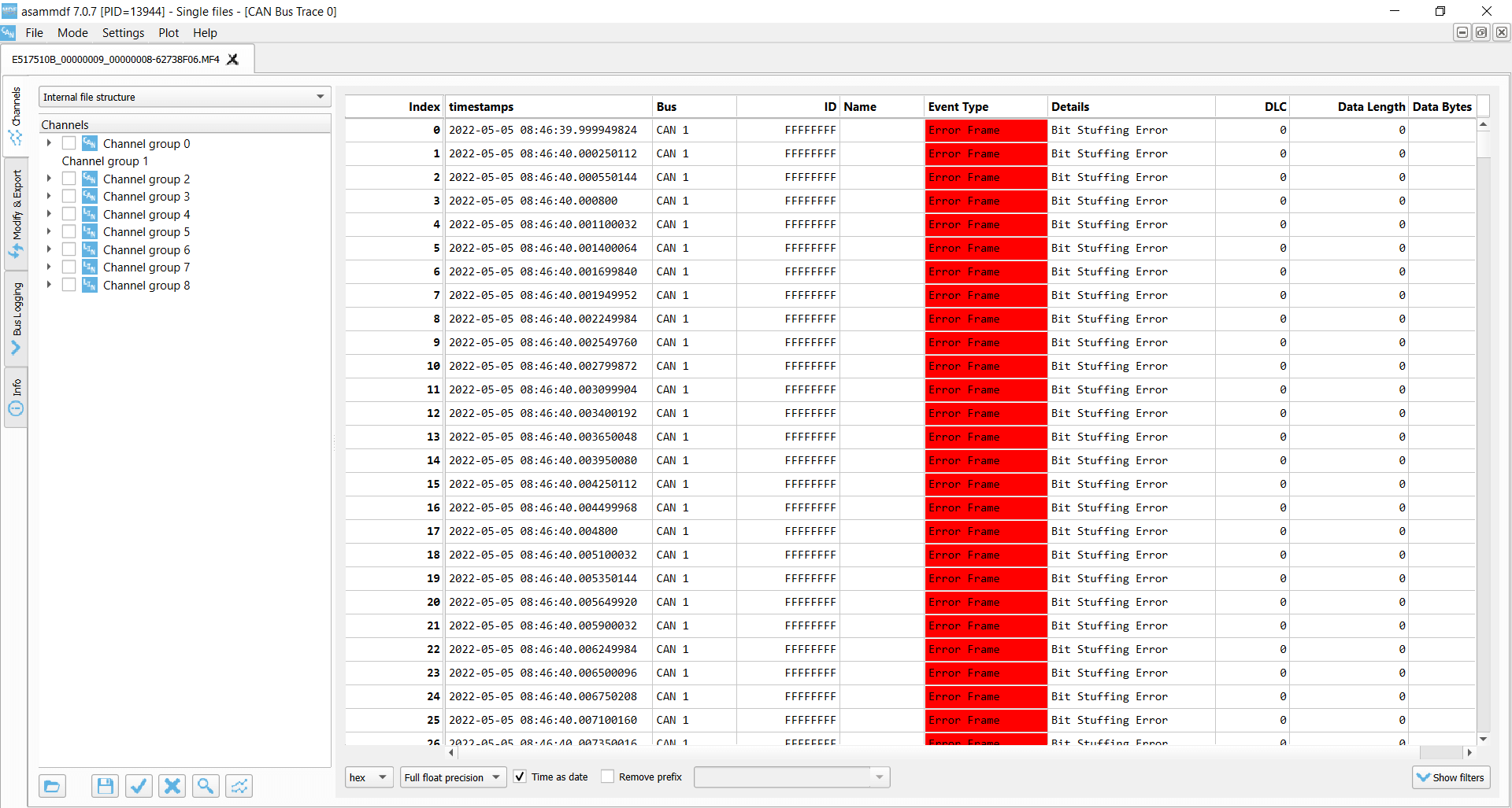
Test #2: Removing the CAN bus terminal resistor
In this test, we remove the CAN termination in the middle of a log session. This effectively corresponds to
immediately setting the bit level to dominant. As a result, the CANedge2 transmitter immediately starts
logging Bit Errors (which occur when it attempts to transmit a recessive bit, but reads a
dominant bit). The
CANedge2 Receiver logs Bit Stuffing Errors as it detects 6 consecutive dominant bits.
These errors are
recorded until the termination is added again.
Lack of termination is rarely a practical issue if you’re recording data from a vehicle, machine etc.
However, it’s a common issue when working with ‘test bench’ setups. Here, the lack of termination may
cause confusion as it can be difficult to distinguish from an inactive CAN bus. If in doubt, enabling
error frame logging on the CANedge can be useful in troubleshooting.

Transmitter Bit Errors

Receiver Bit Stuffing Errors
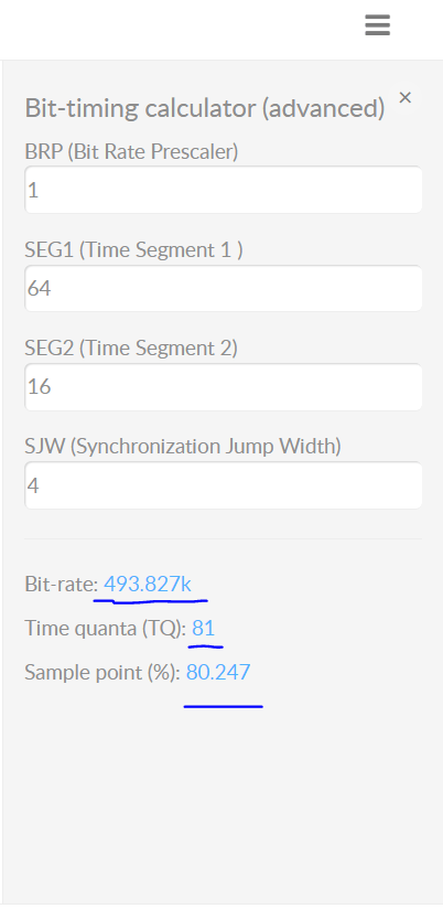
Test #3: Setting an incorrect baud rate
In this test we configure the CANedge receiver node to have a baud rate of 493.827K vs. the baud rate of the
transmitter of 500K. This is a fairly extreme difference and results in ACK Errors for the
transmitter and Bit
Stuffing Errors for the receiver.
In more realistic scenarios, smaller differences in the baud
rate
configuration of
various nodes may cause intermittent error frames and thus message loss.
This example is rather extreme. However, in practice we have sometimes seen CAN buses that use standard
bit rates
(250K, 500K, …), but with specific bit timing settings that differ from the ones that are typically
recommended
(and hence used by the CANedge). This will not lead to a complete shut-down of the communication, but
rather
periodic frame loss of a few percentages. To resolve this, you can construct an ‘advanced bit rate’ in
the
CANedge configuration, essentially setting up the bit-timing to better match the CAN bus you’re logging
from.

Transmitter ACK Error
Receiver Bit Stuffing Errors
Test #4: Removing the acknowledging CAN node
In this test, we use three CANedge units configured as follows:
-
CANedge1: Configured to
acknowledge data -
CANedge2 A:
Configured in ‘silent mode’ (no acknowledgement) -
CANedge2 B:
Configured to transmit a CAN frame every 500 ms
In the default setup, data is transmitted by the CANedge2 B onto the CAN bus and recorded with no errors.
However, if we remove the CANedge1 from the bus there are no longer any CAN nodes to acknowledge the frames
sent by the transmitter.
As a result, the transmitter detects ACK Errors. In response, it increases its
Transmit Error Counter and raises Active Error Flags onto the CAN bus. These are in turn
recorded by CANedge2 A (which silently monitors the bus) as Form Errors.
This is due to the fact that the transmitter raises them upon identifying the lack of a dominant
bit in the ACK slot. As soon as a dominant bit is observed by the receiver in the subsequent EOF field
(which should be recessive), a Form Error is detected.
As evident, the transmitter broadcasts 16 Active Error Flags as its TEC is increased from 0 to 16 x 8 =
128.
The transmitter has now exceeded the threshold of a TEC of 127 and enters Error Passive mode. As a
result,
the transmitter still experiences ACK Errors, but now only raises Passive Error Flags (not visible to
the
receiver). At this point, the transmitter keeps attempting to transmit the same frame — and the receiver
keeps recording this retransmission sequence.
This type of error is one we often encounter in our support tickets. Specifically, users may be trying to
use our CAN loggers to record data from a single CAN node (such as a sensor-to-CAN module like our
CANmod). If they decide to enable ‘silent mode’ on the CANedge in such an installation, no CAN nodes
will acknowledge the single CAN node broadcasting data — and the result will either be empty log files,
or log files filled with retransmissions of the same CAN frame (typically at very high frequency).


Transmitter ACK Errors

Receiver Form Errors
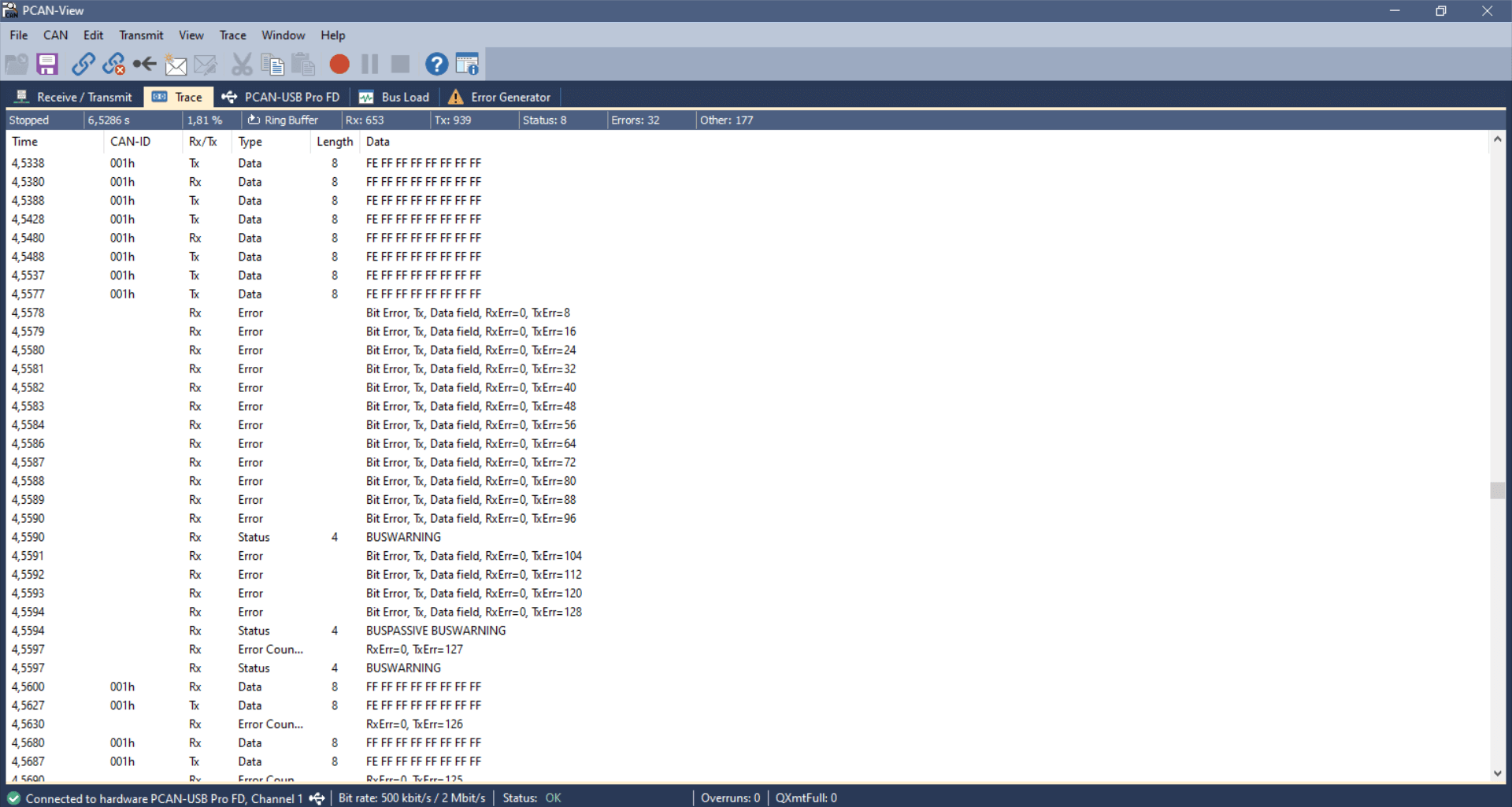
Test #5: CAN frame collisions (no retransmission)
When setting up a CAN bus, it is key to avoid overlapping CAN IDs. Failing to do so can result in frame
collisions
as two CAN nodes may both believe they’ve won the arbitration — and hence start transmitting their frames at
the same time.
To simulate this, we use the same setup as in test #4. In addition, we connect a PCAN-USB device as a
secondary
transmitter.
The CANedge2 transmitter is now configured to output a single CAN frame every 10 ms with CAN ID 1 and a
payload of
eight 0xFF bytes. Further, we configure the CANedge2 to disable retransmission of frames that were disrupted
by
errors. The PCAN-USB outputs an identical CAN frame every 2 ms with the 1st byte of the payload changed to
0xFE. The
PCAN device has retransmissions enabled.
This setup quickly creates a frame collision, resulting in the CANedge and PCAN transmitters detecting a
Bit
Error.
In response to this, both raise an Active Error Flag, which is detected as a Bit Stuffing
Error by the
CANedge
receiver. The PCAN device immediately attempts a retransmission and succeeds, while the CANedge waits with
further
transmission until the next message is to be sent.
This type of error should of course never happen in e.g. a car, since the design and test processes will
ensure
that all CAN nodes communicate via globally unique CAN identifiers. However, this problem can easily
occur if
you install a 3rd party device (e.g. a sensor-to-CAN module) to inject data into an existing CAN bus. If
you do
not ensure the global uniqueness of the CAN IDs of external CAN nodes, you may cause frame collisions
and hence
errors on the CAN bus. This is particularly important if your external CAN node broadcasts data with
high
priority CAN IDs as you may then affect safety critical CAN nodes.


USB-to-CAN transmitter Bit Error
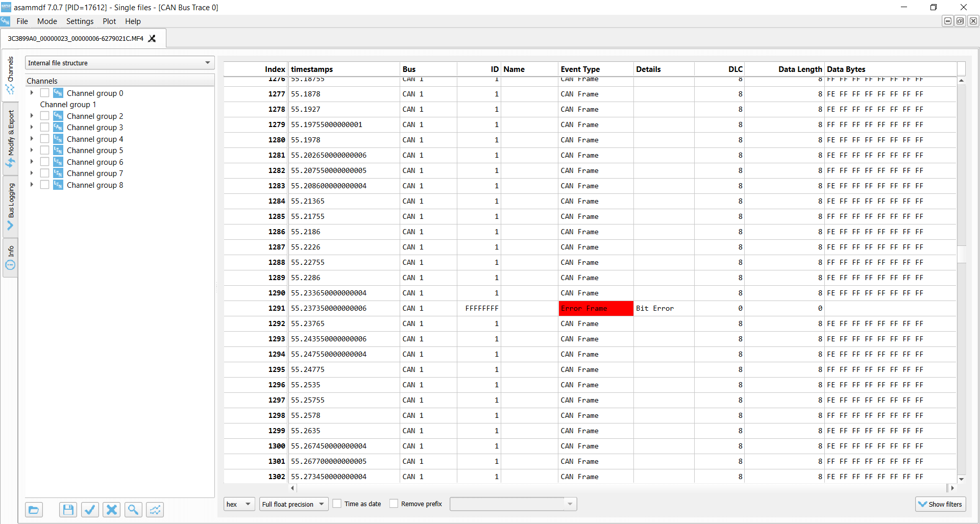
CANedge transmitter Bit Error
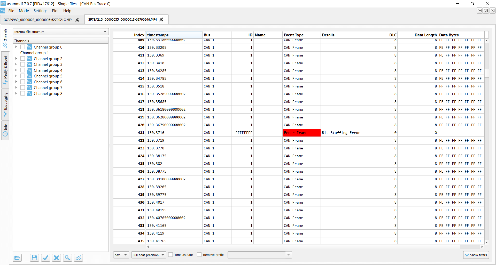
CANedge receiver Bit Stuffing Error
Test #6: CAN frame collisions (incl. retransmission)
In this test, we use the same setup as before, but we now enable retransmissions on the CANedge2 transmitter.
In this case, the frame collision results in a sequence of subsequent frame collisions as both the CANedge2
and the PCAN-USB device attempt to re-transmit their disrupted messages.
Due to the resulting Bit Errors, both raise a total of 16 Active Error Flags, which are detected as
Bit Stuffing Errors
by the silent CANedge2 receiver. Both transmitters then enter Error Passive mode and stop raising Active Error
Flags, meaning none of them can destroy CAN frames on the bus. As a result, one of the transmitters will
succeed in transmitting a full message, thus ending the retransmission frenzy — and enabling both devices to
resume transmission. However, this only lasts for a few seconds before another collision occurs.
The collision handling is a good example of how effective the CAN error handling is at ‘shutting down’
potentially
problematic sequences and enabling CAN nodes to resume communication. If a frame collision occurs, it is likely
that both CAN nodes will be set up to attempt retransmission, which would cause a jam if not for the error
handling and confinement.
USB-to-CAN transmitter Bit Errors x 16
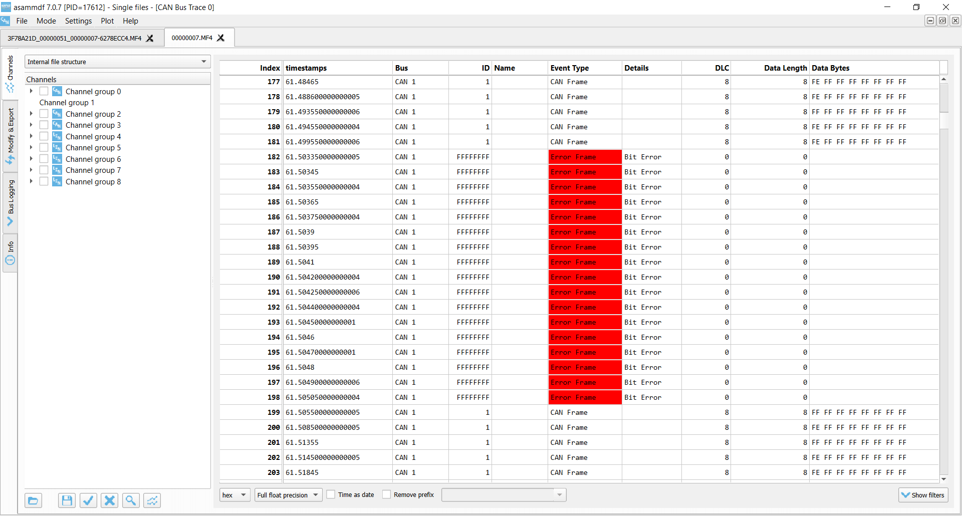
CANedge transmitter Bit Errors x 16

CANedge receiver Bit Stuffing Errors x 16
Similar to CAN bus errors, the LIN protocol also specifies a set of four error types, which we outline briefly below.
The CANedge supports both CAN/LIN error frame logging.
As for the CAN CRC Error, this error type implies that a LIN node has calculated a different checksum vs. the one
embedded in the LIN bus frame by the transmitter. If you’re using the CANedge as a LIN Subscriber, this error
may indicate that you’ve configured the device ‘frame table’ with incorrect identifiers for some of the LIN
frames on the bus.
This can in turn be used to ‘reverse engineer’ the correct lengths and IDs of proprietary LIN frames via a
step-by-step procedure. See the CANedge Docs for details.
These occur if a specific part of the LIN message does not match the expected value, or if there is a mismatch
between what is transmitted vs. read on the LIN bus.
This error indicates an invalid synchronization field in the start of the LIN frame. It can also indicate a large
deviation between the configured bit rate for a LIN node vs. the bit rate detected from the synchronization
field.
Transmission errors can occur for LIN identifiers registered as SUBSCRIBER messages. If there are no nodes
responding to a SUBSCRIBER message, a transmission error is logged.
Example use cases for CAN error frame logging
CAN bus diagnostics in OEM prototype vehicles
An automotive OEM may have the need to record CAN error frames in the field during late stage prototype
testing. By deploying a CANedge, the OEM engineering team will both be able to troubleshoot issues based on
the actual CAN signals (speed, RPM, temperatures) — as well as issues related with the lower layer CAN
communication in their prototype systems. This is particularly vital if the issues of interest are
intermittent and e.g. only happen once or twice per month. In such scenarios, CAN bus interfaces are not
well suited — and it becomes increasingly relevant to have a cost-effective device to enable scalable
deployments for faster troubleshooting.


Remotely troubleshooting CAN errors in machinery
An OEM or aftermarket user may need to capture rare CAN error events in their machines. To do so, they deploy
a CANedge2 to record the CAN data and related error frames — and automatically upload the data via WiFi to
their own cloud server. Here, errors are automatically identified and an alert is sent to the engineering
team to immediately allow for diagnosing and resolving the issue.
FAQ
No, error frame logging is a highly specific functionality — and only relevant if you know that you need to
record this information. Typically, it’s mainly of value during diagnostics by OEM engineers — and less so for
aftermarket users. In addition, if systematic errors occur they can quickly bloat the log file size.
With the CANedge2 you can of course enable/disable error frame logging over-the-air.
Yes, the CANedge is able to record all CAN/LIN error types. It does, however, not currently record its own error
counter status as this is deemed less relevant from a logging perspective.
The CANedge is only able to raise error flags onto the CAN bus if it is configured in its ‘normal’ mode, in which
it is also able to transmit messages. If in ‘restricted’ mode it can listen to CAN frames and acknowledge CAN
frames — but not raise Active Error Flags onto the bus. In ‘monitoring’ mode (aka ‘silent mode’) it can listen
to the CAN bus traffic, but not acknowledge messages nor raise Active Error Flags.
The CANedge will always record internal CAN/LIN error frames.
If a CAN frame is erroneous, resulting in an error frame, the CANedge generally only records the error type —
without any data related to the erroneous frame (beyond the timestamp). One exception to this rule is for
acknowledgement errors, where the CANedge will still record unacknowledged CAN frames (incl. from retransmission
attempts).
Some researchers have pointed out the risk that ‘bad actors’ could utilize the CAN bus error handling
functionality to enforce remote ‘bus off’ events for safety-critical ECUs. This is a good example of why CAN bus
data loggers & interfaces like the CANedge2 with remote
over-the-air data transfer and updates need to be highly secure (see also our intro to CAN
cybersecurity). For a nice overview of a remote bus off attack, see this
intro by Adrian Colyer.
For more intros, see our guides section — or download the
‘Ultimate Guide’ PDF.
Need to log CAN bus data & errors?
Get your CAN logger today!
Recommended for you
Один из немаловажных аспектов работы CAN шины является обработка прерываний bxCan. Их не так уж и много, но при правильной их настройке и обработке мы сможем обеспечить максимальную работоспособность и высокую отказоустойчивость нашего устройства. Поэтому следует обратить наше внимание на то, как это сделать правильно — создать необходимый минимум.
Теория
Начнем опять с теории и обратимся к Reference Maanual от ST Microelectronics.
Для начала мы попытаемся разобраться с механизмом прерываний микроконтроллера STM32F103C6, затем пройдемся по регистрам контроллера и, затем, выстроим некий шаблон, который мы сможем использовать в своих проектах.
Прерывания
Для bxCan может быть назначено четыре прерывания. Каждый из источников прерываний может быть включен или выключен независимо друг от друга в регистре CAN_IER (CAN Interrupt Enable Register).
Вот схема отработки прерываний приведенная в мануале:
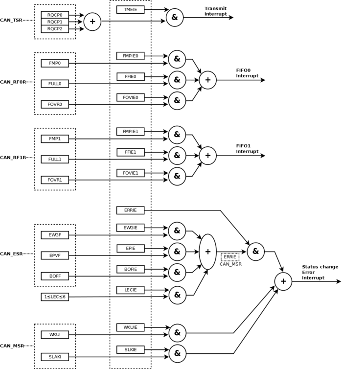
Рис. 1. Флаги событий и формирование прерываний
Как видим на рисунке 1, прерывания сгруппированы в четыре группы:
• Transmit interrupt (Прерывание при передаче сообщения) — может быть вызвано следующими событиями:
— Выполнена передача и освобожден mailbox 0. Бит RQCP0 в регистре CAN_TSR установлен;
— Выполнена передача и освобожден mailbox 1. Бит RQCP1 в регистре CAN_TSR установлен;
— Выполнена передача и освобожден mailbox 2. Бит RQCP2 в регистре CAN_TSR установлен.
• FIFO0 interrupt (Прерывание связанное с входящим буфером FIFO0) — вызывается по следующим событиям:
— Прием нового сообщения, биты FMP0 в регистре CAN_RF0R не равны «00». В принципе значение этого регистра говорит нем о том, сколько сообщений в буфере FIFO еще не обработано программой;
— Буфер FIFO0 заполнен. Бит FULL0 в регистре CAN_RF0R установлен — сообщает нам о том, что в буфере FIFO0 больше нет свободного места;
— Переполнение буфера FIFO0. Бит FOVR0 в регистре CAN_RF0R установлен — возникает в случае когда буфер FIFO0 заполнен и по шине принято еще одно сообщение. Что с этим сообщением произойдет, мы указываем в настройках инициализации CAN (параметр CAN_RFLM).
• FIFO1 interrupt (Прерывание связанное с входящим буфером FIFO1) — вызывается по следующим событиям:
— Прием нового сообщения, биты FMP1 в регистре CAN_RF1R не равны «00». В принципе значение этого регистра говорит нем о том, сколько сообщений в буфере FIFO еще не обработано программой;
— Буфер FIFO1 заполнен. Бит FULL1 в регистре CAN_RF0R установлен — сообщает нам о том, что в буфере FIFO1 больше нет свободного места;
— Переполнение буфера FIFO1. Бит FOVR1 в регистре CAN_RF0R установлен — возникает в случае когда буфер FIFO1 заполнен и по шине принято еще одно сообщение. Что с этим сообщением произойдет, мы указываем в настройках инициализации CAN (параметр CAN_RFLM).
• Error and Status change Interrupt (Прерывание по возникновению ошибок и изменению состояния bxCAN) — вызывается по следующим событиям:
— Возникновение ошибки. Информация об ошибке хранится в регистре CAN Error (CAN_ESR);
— «Просыпание» контроллера — выход из режима сна, когда на Rx появился сигнал CAN шины;
— Переход в спящий режим.
Четвертая группа отвечает за прерывания не только ошибок, но, как видно из названия, и за изменения статуса (режима) bxCan.
Регистры
Полное описание регистров bxCan я приведу в отдельной статье, здесь же мы коснемся лишь некоторых из них, которые непосредственно рассматриваются в рамках данной статьи.
Для того, чтобы мы смогли программно обработать прерывания bxCan, необходимо изучить регистры микроконтроллера, которые непосредственно связаны с этими прерываниями. Разработчики ST Microelectronix постарались для нас и большинство функционала для работы CAN шины возложили на аппаратную часть микроконтроллера, но все же нам придется выполнить некоторые действия самостоятельно.
За обработку ошибок, включение/выключение прерываний CAN шины, а также за информацию о текущем статусе шины и ошибок в bxCan отвечают шесть регистров, которые мы сейчас и изучим:
CAN master status register (CAN_MSR)
Один из основных регистров bxCAN. Он отображает текущее состояние CAN устройства и позволяет программному обеспечению контролировать более детально работу bxCan.
В большинстве случаев нет необходимости досконально контролировать аппаратную часть, сама bxCan превосходно с этим справляется, но в некоторых случаях будет полезно понимать предоставленные нам возможности и инструменты.
CAN Master Status Register предоставляет нам информацию о том, в каком состоянии находится bxCan и сообщает нам о прерываниях, если они установлены.
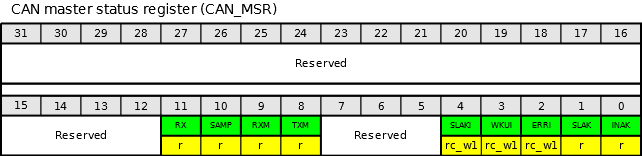
Рис. 2. CAN master status register.
Address offset: 0x04
Reset value: 0x0000 0C02
| Биты | Название | Описание |
|---|---|---|
| 31:12 | Зарезервировано | |
| 11 | RX — CAN Rx signal | CAN Rx сигнал. Контролирует фактическое состояние пина CAN_Rx |
| 10 | SAMP — Last sample point | Последнее принятое значение. Значение RX на последней точки выборки (фактически значение последнего принятого бита). |
| 9 | RXM — Receive mode | Режим передачи. Сообщает, что bxCan находится в режиме передачи сообщения. |
| 8 | TXM — Transmit mode | Режим приема. Сообщает, что bxCan находится в режиме приема сообщения. |
| 7:5 | Зарезервировано | |
| 4 | SLAKI — Sleep acknowledge interrupt | Бит прерывания при переходе в спящий режим. Когда SLKI = 1, то этот бит устанавливается аппаратно и сигнализирует о том, что bxCan вошел в режим «спячки». После установки этого бита генерируется прерывание по переходу в спящий режим (если установлен бит SLKIE в регистре CAN_IER). SLAKI может сбрасываться программно или аппаратно, когда сбрасывается бит SLAK. Примечание: когда бит SLKIE = 0, то нельзя выполнить опрос бита SLAKI. В этом случае необходимо читать значение бита SLAK. |
| 3 | WKUI — Wakeup interrupt | Бит прерывания при возврате из «спящего» режима. Этот бит аппаратно устанавливает сигнал о том, что бит SOF был обнаружен, в то время, как bxCan находился в спящем режиме. Установка этого бита генерирует изменение статуса прерывания, если бит WKUIE регистра CAN_IER был установлен. Сбрасывается этот бит с помощью программного обеспечения. |
| 2 | ERRI — Error interrupt | Бит прерывание по ошибке. Этот бит устанавливается аппаратно, когда бит в регистре CAN_ESR был установлен на обнаружение ошибок и при этом включено соответствующее прерывание в регистре CAN_IER. Установка этого бита генерирует прерывание, если установлен бит ERRIE в регистре CAN_IER. Очищается с помощью программного обеспечения. |
| 1 | SLAK — Sleep acknowledge | Режим сна. Этот бит устанавливается аппаратно и указывает на то, что bxCan находится в режиме сна. Этот бит подтверждает запрос о переходе в «спящий» режим из программного обеспечения (установка бита Sleep в регистре CAN_MCR). Сбрасывается аппаратно, когда bxCan переходит в спящий режим (для синхронизации по CAN — шине). Для синхронизации устройств на шине необходимо контролировать последовательность 11-ти рецессивных бит подряд на сигнале CAN_RX. Процесс выхода из сна запускается, когда сбрасывается бит SLEEP в регистре CAN_MCR. Автоматическое пробуждение из режима сна происходит при установке бита AWUM регистра CAN_MCR. |
| 0 | INAK — Initialization acknowledge | Режим инициализации. Этот бит устанавливается аппаратно и указывает программному обеспечению на то, что bxCan находится в режиме инициализации. Этот бит подтверждает запрос инициализации из программного обеспечения (установлен бит INRQ в регистре CAN_MCR). Бит INAK сбрасывается автоматически, когда bxCan выходит из режима инициализации. Для того чтобы синхронизировать устройства с шиной, необходимо контролировать последовательность 11 рецессивных бит подряд на CAN_RX. |
CAN transmit status register (CAN_TSR)
Этот регистр позволяет нам узнать текущее состояние передачи данных в шину. Из него мы можем получить информацию о количестве исходящих сообщений, заполненности почтовых ящиков, узнать о том, отправлено ли нами сообщение или произошла ошибка, а также позволяет нам прервать отправку пакета, если мы почему-то передумали это делать.
![]()
Рис. 3. CAN transmit status register.
Address offset: 0x08
Reset value: 0x1C00 0000
| Биты | Название | Описание |
|---|---|---|
| 31 | LOW2 — Lowest priority flag for mailbox 2 | Наименьший приоритет для почтового ящика №2. Этот бит устанавливается аппаратно, когда более чем один почтовый ящик находится в обработке, а сообщение в почтовом ящике №2 имеет наименьший приоритет. |
| 30 | LOW1 — Lowest priority flag for mailbox 1 | Наименьший приоритет для почтового ящика №1. Этот бит устанавливается аппаратно, когда более чем один почтовый ящик находится в обработке, а сообщение в почтовом ящике №1 имеет наименьший приоритет. |
| 29 | LOW0 — Lowest priority flag for mailbox 0 | Наименьший приоритет для почтового ящика №0. Этот бит устанавливается аппаратно, когда более чем один почтовый ящик находится в обработке, а сообщение в почтовом ящике №0 имеет наименьший приоритет. Примечание: Биты LOW[2:0] устанавливаются в ноль, когда только один почтовый ящик находится на обработке. |
| 28 | TME2 — Transmit mailbox 2 empty | Почтовый ящик №2 пуст. Этот бит устанавливается аппаратно, когда нет запроса на обработку почтового ящика №2. |
| 27 | TME1 — Transmit mailbox 1 empty | Почтовый ящик №1 пуст. Этот бит устанавливается аппаратно, когда нет запроса на обработку почтового ящика №1. |
| 26 | TME0 — Transmit mailbox 0 empty | Почтовый ящик №0 пуст. Этот бит устанавливается аппаратно, когда нет запроса на обработку почтового ящика №0. |
| 25:24 | CODE[1:0] — Mailbox code | Код почтового ящика. В случае, когда по меньшей мере освобождается один почтовый ящик, значение CODE содержит номер следующего почтового ящика в очереди с наименьшим приоритетом. |
| 23 | ABRQ2 — Abort request for mailbox 2 | Прервать запрос на обработку почтового ящика №2. Устанавливается программно с целью прервать передачу из почтового ящика №2. Сбрасывается автоматически после того, как bxCan очищает почтовый ящик. Установка этого бита не имеет никакого значения, если почтовый ящик не задерживается для передачи. |
| 22:20 | Зарезервировано | |
| 19 | TERR2 — Transmission error of mailbox 2 | Ошибка передачи для почтового ящика №2. Устанавливается, когда произошла ошибка при передаче сообщения из этого почтового ящика. |
| 18 | ALST2 — Arbitration lost for mailbox 2 | Потеря арбитража для почтового ящика №2. Бит устанавливается, если при передачи сообщения устройство проиграла арбитраж. |
| 17 | TXOK2 — Transmission OK of mailbox 2 | Завершение передачи для почтового ящика №2. bxCan обновляет этот бит после каждой попытки передачи из почтового ящика и устанавливает следующие значения: 0 — передача не удалась; 1 — передача была успешной. Этот бит устанавливается аппаратно, когда успешно завершен запрос передачи для почтового ящика №2. |
| 16 | RQCP2 — Request completed mailbox2 | Завершен запрос на передачу для почтового ящика №2. Устанавливается аппаратно, когда был выполнен последний запрос (передан или прерван). Очищается программно путем установки бита в «1» или аппаратно по факту завершения передачи (установка бита TXRQ2 в регистре CAN_TI2R). Очистка этого бита сбрасывает все виды состояния для почтового ящика №2 (TXOK2, ALST2 и TERR2). |
| 15 | ABRQ1 — Abort request for mailbox 1 | Прервать запрос на обработку почтового ящика №1. Устанавливается программно с целью прервать передачу из почтового ящика №1. Сбрасывается автоматически после того, как bxCan очищает почтовый ящик. Установка этого бита не имеет никакого значения, если почтовый ящик не задерживается для передачи. |
| 14:12 | Зарезервировано | |
| 11 | TERR1 — Transmission error of mailbox1 | Ошибка передачи для почтового ящика №2. Устанавливается, когда произошла ошибка при передаче сообщения из этого почтового ящика. |
| 10 | ALST1 — Arbitration lost for mailbox1 | Потеря арбитража для почтового ящика №1. Бит устанавливается, если при передачи сообщения устройство проиграла арбитраж. |
| 9 | TXOK1 — Transmission OK of mailbox1 | Завершение передачи для почтового ящика №1. bxCan обновляет этот бит после каждой попытки передачи из почтового ящика и устанавливает следующие значения: 0 — передача не удалась; 1 — передача была успешной. Этот бит устанавливается аппаратно, когда успешно завершен запрос передачи для почтового ящика №1. |
| 8 | RQCP1 — Request completed mailbox1 | Завершен запрос на передачу для почтового ящика №1. Устанавливается аппаратно, когда был выполнен последний запрос (передан или прерван). Очищается программно путем установки бита в «1» или аппаратно по факту завершения передачи (установка бита TXRQ1 в регистре CAN_TI1R). Очистка этого бита сбрасывает все виды состояния для почтового ящика №1 (TXOK1, ALST1 и TERR1). |
| 7 | ABRQ0 — Abort request for mailbox0 | Прервать запрос на обработку почтового ящика №0. Устанавливается программно с целью прервать передачу из почтового ящика №0. Сбрасывается программно после того, как bxCan очищает почтовый ящик. Установка этого бита не имеет никакого значения, если почтовый ящик не задерживается для передачи. |
| 6:4 | Зарезервировано | |
| 3 | TERR0 — Transmission error of mailbox0 | Ошибка передачи для почтового ящика №0. Устанавливается, когда произошла ошибка при передаче сообщения из этого почтового ящика. |
| 2 | ALST0 — Arbitration lost for mailbox0 | Потеря арбитража для почтового ящика №0. Бит устанавливается, если при передачи сообщения устройство проиграла арбитраж. |
| 1 | TXOK0 — Transmission OK of mailbox0 | Завершение передачи для почтового ящика №0. bxCan обновляет этот бит после каждой попытки передачи из почтового ящика и устанавливает следующие значения: 0 — передача не удалась; 1 — передача была успешной. Этот бит устанавливается аппаратно, когда успешно завершен запрос передачи для почтового ящика №0. |
| 0 | RQCP0 — Request completed mailbox0 | Завершен запрос на передачу для почтового ящика №0. Устанавливается аппаратно, когда был выполнен последний запрос (передан или прерван). Очищается программно путем установки бита в «1» или аппаратно по факту завершения передачи (установка бита TXRQ0 в регистре CAN_TI0R). Очистка этого бита сбрасывает все виды состояния для почтового ящика №0 (TXOK0, ALST0 и TERR0). |
Как правило необходимости напрямую обращаться к этому регистру у нас не будет — можно полностью доверится bxCan. Я вижу потребность в его чтении только в очень сложных проектах, где часть функционала ложится не только на аппаратную часть, но и на программную. Также может потребоваться в случаях, когда необходимо использовать парсер CAN-шины — необходимо более детальное изучение ошибок передачи данных, логирование всего и вся.
Для обработки прерываний передачи сообщений необходимо разрешить прерывание при отправке почтового сообщения (CAN_IT_TME) и, соответственно, добавить это обработчик этого прерывания в тело программы (USB_HP_CAN1_TX_IRQHandler()).
CAN receive FIFO 0 register (CAN_RF0R)
Первый из двух регистров, отвечающих за буфер входящих сообщений FIFO 0.
Из этого регистра мы можем узнать количество почтовых сообщений, а также текущее состояние буфера FIFO 0.
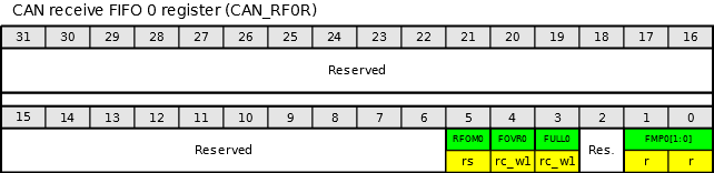
Рис. 4. CAN receive FIFO 0 register.
Address offset: 0x0C
Reset value: 0x0000 0000
| Биты | Название | Описание |
|---|---|---|
| 31:6 | Зарезервировано | |
| 5 | RFOM0 — Release FIFO 0 output mailbox | Буфер FIFO0 освобожден. Устанавливается программно, чтобы освободить (очистить) почтовые ящики буфера FIFO0. Выходной почтовый ящик буфера может быть освобожден только в том случае, если на обработке FIFO0 имеется хотя бы одно сообщение. Устанавливать этот бит, когда FIFO0 пуст — не имеет никакого смысла. Очищается автоматически с помощью аппаратных средств, когда обработаны все сообщения, находящиеся в почтовых ящиках буфера FIFO0. |
| 4 | FOVR0 — FIFO 0 overrun | Буфер FIFO0 переполнен. Этот бит устанавливается аппаратными средствами, когда получено новое сообщение, но буфер FIFO0 уже заполнен. Этот бит необходимо сбрасывать программно. |
| 3 | FULL0 — FIFO 0 full | Буфер FIFO0 заполнен. Устанавливается аппаратно, когда заполнены все три почтовых ящика буфера FIFO0 Этот бит необходимо сбрасывать программно. |
| 2 | Зарезервировано | |
| 1:0 | FMP0[1:0] — FIFO 0 message pending | Количество сообщений в буфере FIFO0. Эти биты указывают, сколько сообщений находится на обработке в буфере FIFO0. FMP увеличивается каждый раз, когда поступает новое сообщение и уменьшается, после обработки каждого сообщения буфера. |
Обработка прерываний для буфера FIFO 0 происходит в функции USB_LP_CAN1_RX0_IRQHandler(). В ней необходимо обработать получение почтовых сообщений, а также проверить состояние ошибок (заполнение или переполнение буфера FIFO 0). Естественно, необходимо включить эти прерывания при настройке bxCan.
Необходимо помнить, что биты FOVR0 и FULL0 сбрасываются вручную.
CAN receive FIFO 1 register (CAN_RF1R)
А это второй регистр, предназначенный для чтения состояния буфера входящих сообщений, но уже для FIFO 1.
Из него мы также можем почерпнуть информацию о том, сколько сообщений у нас хранится и текущий статус самого буфера FIFO 1.

Рис. 5. CAN receive FIFO 1 register.
Address offset: 0x10
Reset value: 0x0000 0000
| Биты | Название | Описание |
|---|---|---|
| 31:6 | Зарезервировано | |
| 5 | RFOM1 — Release FIFO 1 output mailbox | Буфер FIFO1 освобожден. Устанавливается программно, чтобы освободить (очистить) почтовые ящики буфера FIFO1. Выходной почтовый ящик буфера может быть освобожден только в том случае, если на обработке FIFO1 имеется хотя бы одно сообщение. Устанавливать этот бит, когда FIFO1 пуст — не имеет никакого смысла. Очищается автоматически с помощью аппаратных средств, когда обработаны все сообщения, находящиеся в почтовых ящиках буфера FIFO1. |
| 4 | FOVR1 — FIFO 1 overrun | Буфер FIFO1 переполнен. Этот бит устанавливается аппаратными средствами, когда получено новое сообщение, но буфер FIFO1 уже заполнен. Этот бит необходимо сбрасывать программно. |
| 3 | FULL1 — FIFO 1 full | Буфер FIFO1 заполнен. Устанавливается аппаратно, когда заполнены все три почтовых ящика буфера FIFO1 Этот бит необходимо сбрасывать программно. |
| 2 | Зарезервировано | |
| 1:0 | FMP1[1:0] — FIFO 1 message pending | Количество сообщений в буфере FIFO1. Эти биты указывают, сколько сообщений находится на обработке в буфере FIFO1. FMP увеличивается каждый раз, когда поступает новое сообщение и уменьшается, после обработки каждого сообщения буфера. |
Для обработки прерываний для буфера FIFO 1 необходимо включить обработку этих прерываний при настройке bxCan и вставить в модуль функцию CAN1_RX1_IRQHandler(). Также как и с буфером FIFO 0, мы можем в обработчике прерываний выполнить обработку получения почтового сообщения в буфер FIFO 1, а также проверить состояние ошибок буфера и сбросить их после обработки.
Также напомню о необходимости сбрасывать биты FOVR1 и FULL1 вручную.
CAN interrupt enable register (CAN_IER)
Мы добрались до регистра, который непосредственно отвечает за включение прерываний bxCAN. Установив необходимые нам биты, мы сможем выполнить обработку прерываний. Напомню, что включение прерываний само по себе недостаточно, необходимо еще и включить сами прерывания и добавить их обработчики в тело программы, иначе наша программа при возникновении прерывания перейдет в прерывание по умолчанию и просто «зависнет». Но об этом поговорим чуть ниже, где я приведу несколько примеров.
Итак, нам необходимо включить прерывания. Сделать это мы можем установив соответствующие биты в регистре CAN interrupt enable register (CAN_IER).
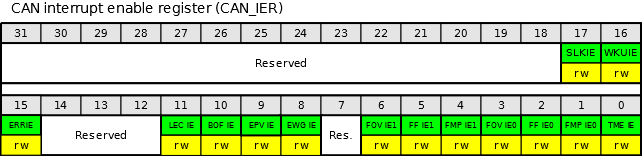
Рис. 6. CAN interrupt enable register.
Address offset: 0x14
Reset value: 0x0000 0000
| Биты | Название | Описание |
|---|---|---|
| 31:18 | Зарезервировано | |
| 17 | SLKIE — Sleep interrupt enable | Прерывание при переходе в спящий режим. Вызывается, когда bxCan переходит в «спящий» режим при установленном бите SLAKI регистра CAN_MSR. 0: Прерывание не генерируется 1: Прерывание генерируется |
| 16 | WKUIE — Wakeup interrupt enable | Прерывание при выходе из спящего режима. Вызывается, когда bxCan выходит из спящего режима при установленном бите WKUI регистра CAN_MSR. 0: Прерывание не генерируется 1: Прерывание генерируется |
| 15 | ERRIE — Error interrupt enable | Прерывание при возникновении ошибки. 0: Прерывание не генерируется 1: Генерируется прерывание когда есть описание ошибки в регистре CAN_ESR. |
| 14:12 | Зарезервировано | |
| 11 | LECIE — Last error code interrupt enable | Прерывание при возникновении ошибки приема-передачи. Вызывается, когда установлены биты LEC[2:0] (регистр CAN_ESR) аппаратной частью bxCan. 0: Бит ERRI не будет установлен 1: Бит ERRI будет установлен при обнаружении ошибки на шине. |
| 10 | BOFIE — Bus-off interrupt enable | Прерывание при переходе в режим Bus-Off. Вызывается при переходе bxCan в режим Bus-Off при установленном бите BOFF регистра CAN_ESR. 0: Бит ERRI не будет установлен 1: Бит ERRI будет установлен |
| 9 | EPVIE — Error passive interrupt enable | Прерывание при достижении пассивного уровня ошибок. Вызывается когда счетчики ошибок приема или передачи превышают значение 127 при установленном бите EPVF регистра CAN_ESR. 0: Бит ERRI не будет установлен 1: Бит ERRI будет установлен |
| 8 | EWGIE — Error warning interrupt enable | Прерывание при достижении предупреждающего уровня ошибок. Вызывается когда счетчики ошибок приема или передачи превышают либо равны значению 96 при установленном бите EWGF. 0: Бит ERRI не будет установлен 1: Бит ERRI будет установлен |
| 7 | Зарезервировано | |
| 6 | FOVIE1 — FIFO overrun interrupt enable | Прерывание при переполнении буфера FIFO1. Вызывается, когда буфер FIFO1 заполнен и получено еще один пакет данных при установленном бите FOVR регистра CAN_RF1R. 0: Прерывание не генерируется 1: Генерируется прерывание |
| 5 | FFIE1 — FIFO full interrupt enable | Прерывание при заполнении буфера FIFO1. Вызывается когда в буфере FIFO1 заполнены все три почтовых ящика при установленном бите FULL регистра CAN_RF1R. 0: Прерывание не генерируется 1: Генерируется прерывание |
| 4 | FMPIE1 — FIFO message pending interrupt enable | Прерывание при получении пакета из шины. Вызывается когда в буфер FIFO1 получено очередное сообщение (при значении бита FMP[1:0] регистра CAN_RF1R не равном 00b). 0: Прерывание не генерируется 1: Генерируется прерывание |
| 3 | FOVIE0 — FIFO overrun interrupt enable | Прерывание при переполнении буфера FIFO0. Вызывается, когда буфер FIFO0 заполнен и получено еще один пакет данных при установленном бите FOVR регистра CAN_RF0R. 0: Прерывание не генерируется 1: Генерируется прерывание |
| 2 | FFIE0 — FIFO full interrupt enable | Прерывание при заполнении буфера FIFO0. Вызывается когда в буфере FIFO0 заполнены все три почтовых ящика при установленном бите FULL регистра CAN_RF0R. 0: Прерывание не генерируется 1: Генерируется прерывание |
| 1 | FMPIE0 — FIFO message pending interrupt enable | Прерывание при получении пакета из шины. Вызывается когда в буфер FIFO0 получено очередное сообщение (при значении бита FMP[1:0] регистра CAN_RF0R не равном 00b). 0: Прерывание не генерируется 1: Генерируется прерывание |
| 0 | TMEIE — Transmit mailbox empty interrupt enable | Прерывание при освобождении исходящего почтового ящика. Вызывается при окончании передачи сообщения при установленном бите RQCPx регистра CAN_TSR. 0: Прерывание не генерируется 1: Генерируется прерывание |
Если Вы новичок и только начинаете изучать протокол CAN и его использование на микроконтроллерах семейства STM32, то можно ограничиться одним прерыванием FMPIE0 (FIFO 0 message pending interrupt) и TMEIE (Transmit mailbox empty interrupt), которые отвечает за обработку получения входящего пакета в буфер FIFO 0, а также за обработку окончания отправки пакета в шину соответственно. Для первоначального изучения и тестирования этого вполне хватит, а дальше уже требуется более глубокое понимание физики процессов и специфики работы CAN шины.
CAN error status register (CAN_ESR)
Регистр отвечает за состояние ошибок при работе с bxCan.
Управление ошибками, как описано в протоколе CAN, обрабатывается полностью аппаратными средствами с помощью счетчиков ошибок передачи (TEC — Transmit error counter) и счетчиков ошибок приема сообщений (REC — Receive error counter), которые увеличивают или уменьшают свое значение в соответствии с состоянием ошибки.
Оба счетчика могут быть прочитаны с помощью программного обеспечения, чтобы определить стабильность сети.
Кроме того, аппаратное обеспечение может предоставлять более подробную информацию о текущем состоянии ошибок (LEC — Last error code).
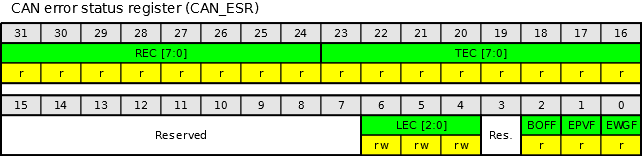
Рис. 7. CAN error status register.
Address offset: 0x18
Reset value: 0x0000 0000
| Биты | Название | Описание |
|---|---|---|
| 31:24 | REC[7:0] — Receive error counter | Счетчик ошибок приема пакетов. Исполняющая часть механизма контроля состояния протокола CAN. В случае возникновения ошибки во время приема пакета, этот счетчик увеличивается на 1 или на 8 в зависимости от состояния ошибки (по определению стандарта CAN). После каждого успешного приема счетчик уменьшается на единицу или сбрасывается до 120, если его значение было выше, чем 128. Если значение счетчика превышает 127, то контроллер bxCan переходит в пассивное состояние ошибки (устанавливается бит EPVF). |
| 23:16 | TEC[7:0] — Transmit error counter | Счетчик ошибок передачи пакетов. Аналогично REC, только для ошибок передачи. |
| 15:17 | Зарезервировано | |
| 6:4 | LEC[2:0] — Last error code | Код последней ошибки. Это поле устанавливается аппаратно и содержит значение, которое указывает на вид последней ошибки, обнаруженной на CAN шине. Если сообщение было передано или получено без ошибок, то значение этих битов будет сброшено в ноль. Также программно можно установить эти биты в значение 0b111, что указывает, что ошибка установлена с помощью программного обеспечения. Коды ошибок: 000 — Нет ошибок 001 — Stuff error 010 — Form error 011 — Acknowledgment Error 100 — Bit recessive Error 101 — Bit dominant Error 110 — CRC Error 111 — Set by software Описание ошибок приведено ниже в таблице №4. |
| 3 | Зарезервировано | |
| 2 | BOFF — Bus-off flag | Bus-off флаг. Этот бит устанавливается, когда bxCan переходит в режим Bus-off. Режим Bus-off вводится, когда счетчик ошибок передачи (TEC) становится больше чем 255. |
| 1 | EPVF — Error passive flag | Флаг пассивной ошибки. Этот бит устанавливается аппаратно, когда достигнут пассивный предел счетчиков ошибок (Счетчик приема и/или передачи больше 127). |
| 0 | EWGF — Error warning flag | Флаг предупреждения об ошибках. Бит устанавливается аппаратно, когда достигнут предел предупреждения (Счетчик ошибок приема и/или передачи ≥ 96). |
Согласно описанию протокола CAN принято увеличивать счетчик ошибок REC (Receive error counter) на одну единицу при каждой обнаруженной ошибке приема на шине, а счетчик ошибок TEC (Transmit error counter) увеличивать на 8 при каждой ошибке передачи пакетов. Это связано стем, что существует предположение о том, что с наибольшей вероятностью источником ошибок на шине является передающий узел.
Уменьшение счетчика ошибок происходит автоматически на единицу при каждом успешном приеме или передаче сообщений по шине для счетчиков REC и TEC соответственно.
Восстановление BUS-OFF
Состояние шины Bus-Off устанавливается, когда счетчик ошибок передачи превышает 255, при этом устанавливается бит BOFF регистра CAN_ESR. В этом режиме bxCan фактически перестает принимать и передавать пакеты по шине.
При настройке bxCAN можно установить бит ABOM, который отвечает за то, что если шина перейдет в режим Bus-off, то bxCan автоматически начнет проверять сигнал CAN_RX для восстановления шины. Если бит ABOM не установлен, то разработчику необходимо контролировать этот процесс самостоятельно и в случае возникновения ошибки и перехода в режим Bus-off необходимо заново проинициализировать bxCan.
Обратите внимание, что bxCan слушает порт CAN_RX только в нормальном режиме работы. Если bxCan находится в режиме инициализации, то автоматического восстановления шины не произойдет.
Долгое время не мог понять, что это за 11 рецессивных бит 128 раз подряд и где их необходимо взять и куда подать. Путем гугления и раскурки мануалов понял, что это указывается время, через которое контроллер CAN шины автоматически выйдет из режима Bus-Off и оно равно времени, которое потребуется для передачи 11 рецессивных бит 128 раз подряд.
Другими словами, контроллер автоматически выйдет из режима Bus-Off, когда на CAN шине будет «тишина» в течении времени, равному времени передачи 11 бит * 128 раз. Естественно, если в настройках контроллера мы ему указали, что он может автоматически выходить из этого режима (установлен бит ABOM регистра CAN_MCR).
Практика
Вроде все моменты, которые касаются обработки прерываний bxCan мы рассмотрели. Текста очень много, но как это применить на практике?
Давайте разбираться.
Для начала нам необходимо определится с тем, какие прерывания bxCan мы будем использовать. Конечно можно ограничиться прерыванием на получение сообщения в буфер FIFO, но мы же не ищем легких путей, поэтому проинициализируем сразу все.
За включение/отключение прерываний bxCan отвечает функция CAN_ITConfig, эти действия выполняются в модуле инициализации can шины совместно с настройкой прерываний NVIC:
Листинг №1. Включение прерываний bxCan
	// CAN Transmit mailbox empty Interrupt enable
	// Обрабатывается в прерывании USB_HP_CAN1_TX_IRQHandler
	CAN_ITConfig(CAN1, CAN_IT_TME, ENABLE);         // Прерывание при освобождении исходящего почтового ящика
	// CAN Receive Interrupt enable
	// Обрабатывается в прерывании USB_LP_CAN1_RX0_IRQHandler
	CAN_ITConfig(CAN1, CAN_IT_FMP0, ENABLE);        // Прерывание получения пакета в буфер FIFO 0
	CAN_ITConfig(CAN1, CAN_IT_FF0, ENABLE);         // Прерывание при заполнении буфера FIFO 0
	CAN_ITConfig(CAN1, CAN_IT_FOV0, ENABLE);        // Прерывание при переполнении буфера FIFO 0

	// Обрабатывается в прерывании CAN1_RX1_IRQHandler
	CAN_ITConfig(CAN1, CAN_IT_FMP1, ENABLE);        // Прерывание получения пакета в буфер FIFO 1
	CAN_ITConfig(CAN1, CAN_IT_FF1, ENABLE);         // Прерывание при заполнении буфера FIFO 1
	CAN_ITConfig(CAN1, CAN_IT_FOV1, ENABLE);        // Прерывание при переполнении буфера FIFO 1

	// CAN Operating Mode Interrupt enable
	// Обрабатывается в прерывании CAN1_SCE_IRQHandler
	CAN_ITConfig(CAN1, CAN_IT_WKU, ENABLE);         // Прерывание при "пробуждении" - выход из "спящего" режима
	CAN_ITConfig(CAN1, CAN_IT_SLK, ENABLE);         // Прерывание при переходе в "спящий" режим

	// CAN Error Interrupts
	// Обрабатывается в прерывании CAN1_SCE_IRQHandler
	CAN_ITConfig(CAN1, CAN_IT_EWG, ENABLE);         // Error warning Interrupt (error counter >= 96)
	CAN_ITConfig(CAN1, CAN_IT_EPV, ENABLE);         // Error passive Interrupt (error counter > 127)
	CAN_ITConfig(CAN1, CAN_IT_BOF, ENABLE);         // Bus-off Interrupt (error counter > 255)
	CAN_ITConfig(CAN1, CAN_IT_LEC, ENABLE);         // Last error code - при возникновении ошибок приема-передачи
	CAN_ITConfig(CAN1, CAN_IT_ERR, ENABLE);         // Прерывание при возникновении ошибок bxCan


	// NVIC Configuration
	NVIC_InitTypeDef NVIC_InitStructure;

	// Enable CAN1 TX0 interrupt IRQ channel
	NVIC_InitStructure.NVIC_IRQChannel = USB_HP_CAN1_TX_IRQn;
	NVIC_InitStructure.NVIC_IRQChannelPreemptionPriority = 0;
	NVIC_InitStructure.NVIC_IRQChannelSubPriority = 0;
	NVIC_InitStructure.NVIC_IRQChannelCmd = ENABLE;
	NVIC_Init(&NVIC_InitStructure);

	// Enable CAN1 RX0 interrupt IRQ channel
	NVIC_InitStructure.NVIC_IRQChannel = USB_LP_CAN1_RX0_IRQn;
	NVIC_InitStructure.NVIC_IRQChannelPreemptionPriority = 0;
	NVIC_InitStructure.NVIC_IRQChannelSubPriority = 0;
	NVIC_InitStructure.NVIC_IRQChannelCmd = ENABLE;
	NVIC_Init(&NVIC_InitStructure);

	// Enable CAN1 RX1 interrupt IRQ channel
	NVIC_InitStructure.NVIC_IRQChannel = CAN1_RX1_IRQn;
	NVIC_InitStructure.NVIC_IRQChannelPreemptionPriority = 0;
	NVIC_InitStructure.NVIC_IRQChannelSubPriority = 0;
	NVIC_InitStructure.NVIC_IRQChannelCmd = ENABLE;
	NVIC_Init(&NVIC_InitStructure);

	// Enable CAN1 SCE (Status Change Error) interrupt IRQ channel
	NVIC_InitStructure.NVIC_IRQChannel = CAN1_SCE_IRQn;
	NVIC_InitStructure.NVIC_IRQChannelPreemptionPriority = 0;
	NVIC_InitStructure.NVIC_IRQChannelSubPriority = 0;
	NVIC_InitStructure.NVIC_IRQChannelCmd = ENABLE;
	NVIC_Init(&NVIC_InitStructure);
После того, как с помощью функции CAN_ITConfig() мы проинициализировали необходимые нам прерывания, необходимо включить обработчики этих прерываний. Делается это через NVIC. Если мы забудем хотя бы одно из них включить, то микроконтроллер при возникновении прерывания, которое мы забыли обработать, выкинет нас в стандартный обработчик прерываний и просто зависнет. Поможет только перезагрузка процессора, так как он будет сидеть в «вечном» цикле и ни на что больше реагировать не будет.
А теперь, чтобы этого не произошло, нам необходимо вставить в наш программный код функции обработки прерываний. Всего их четыре: прерывание при освобождении исходящего почтового ящика, два прерывания для буферов FIFO 1 и 2, а также прерывание по обработке ошибок и входа/выхода в «режим сна».
Обработка прерываний при освобождении исходящего почтового ящика
За обработку прерывания при освобождении исходящего почтового ящика отвечает функция USB_HP_CAN1_TX_IRQHandler(). Нам необходимо проверить флаг прерывания и, если он установлен, сбросить его и выполнить код обработки прерывания:
Листинг №2. Обработка прерываний bxCan для исходящего почтового ящика
void USB_HP_CAN1_TX_IRQHandler(void)
{
	// CAN Transmit mailbox empty Interrupt enable
	// Обработаем прерывания при освобождении исходящего почтового ящика
	if (CAN_GetITStatus(CAN1, CAN_IT_TME)==SET) {       // Прерывание при освобождении исходящего почтового ящика
		CAN_ClearITPendingBit(CAN1, CAN_IT_TME);

		// Вставляем свой код по обработке прерывания
	}
}
Функция CAN_GetITStatus() возвращает текущее состояние флага прерывания, значение может быть равным SET или RESET («Установлен» или «сброшен» соответственно). Значение SET говорит нам о том, что бит установлен и нам необходимо обработать это прерывание и не забыть сбросить его флаг.
Следует помнить о том, что необходимо всегда производить сброс флага прерывания, иначе оно будет вызываться постоянно. Исключение составляют только флаги прерываний ошибок, они почти все сбрасываются аппаратно, подробнее можно посмотреть в описании функции CAN_ClearITPendingBit().
Проверять освобождение исходящего почтового ящика имеет смысл, если Вы пересылаете большой объем данных по Can-шине: при обработке отправки сообщения выставляется флаг отправки сообщения, а в прерывании проверяется была выполнена отправка данных или нет. Если отправка была завершена без ошибок, то устанавливаем в флаг значение без ошибок и отправляем следующий пакет данных, иначе устанавливаем в флаг код ошибки и обрабатываем ее в модуле программы.
Несмотря на то, что исходящих почтовых ящиков у нас три, проверять отправку сообщений я все же рекомендую, иначе вполне вероятны ситуации, когда в результате проигрыша арбитража или возникновении ошибок на линии bxCan не сможет отправить сообщения, а мы в этот момент, не проверив статус отправки, будем давать ему новые на отправку. Возникнет сбой, который нам не нужен.
Проверить статус отправки сообщения можно не только с помощью прерываний, но и в момент отправки сообщения (это наверное самый оптимальный вариант):
Листинг №3. Отправка сообщения с проверкой статуса отправки
	uint32_t i = 0;
	uint8_t TransmitMailbox = 0;

	...

	TransmitMailbox = CAN_Transmit(CAN1, &TxMessage);
	i = 0;
	while ((CAN_TransmitStatus(CAN1, TransmitMailbox) != CANTXOK) && (i != 0xFF)) 	{
		i++;
	}
При передаче сообщения через функцию CAN_Transmit, она нам возвращает номер исходящего почтового ящика, в который помещено сообщение. Затем мы в цикле проверяем, отправил ли bxCan наше сообщение или нет. Если отправка прошла успешно, то статус отправки сообщения из почтового ящика будет равен CANTXOK.
По окончанию цикла while() проверяем значение переменной «i». Если оно у нас равно 0xFF, значит отправка не удалась и тут мы уже думаем что сделать: то ли сбросить отправку сообщения, то ли обработать ошибку.
Вообщем все на усмотрение разработчика.
Обработка прерываний входящего буфера сообщений FIFO 0
За прерывания для входящего буфера сообщений FIFO 0 отвечают флаги CAN_IT_FMP0, CAN_IT_FF0 и CAN_IT_FOV0.
| Наименование | Описание |
|---|---|
| CAN_IT_FMP0 | Прерывание срабатывает при получении очередного сообщения в буфер FIFO 0. |
| CAN_IT_FF0 | Прерывание возникает при заполнении всех трех почтовых ящиков буфера FIFO 0. |
| CAN_IT_FOV0 | А это прерывание возникает если у нас все три почтовых ящика буфера FIFO 0 заполнены и мы получаем четвертое сообщение по шине. У нас происходит переполнение буфера. |
Таб. 1. Прерывания буфера FIFO 0
Заполнение, а тем более переполнение буфера входящих сообщений говорит о том, что Ваша программа не успевает их обрабатывать. Здесь уже необходимо искать причину в организации работы CAN шины и поиграться с установкой фильтров сообщений.
Фильтры помогут на аппаратном уровне отсеивать пакеты с ненужными нам данными, чтобы не тратить время и ресурсы процессора на обработку ненужной информации. Подробнее работу с фильтрами я описал в статье STM32. Почтовые ящики. Фильтры пакетов CAN.
Действия по обработке данных прерываний возлагаются на разработчика и описываются в функции USB_LP_CAN1_RX0_IRQHandler().
Листинг №4. Обработка прерываний bxCan для буфера FIFO 0
void USB_LP_CAN1_RX0_IRQHandler(void)
{
	CanRxMsg RxMessage;

	// CAN Receive Interrupt enable FIFO 0
	// Обработаем прерывания приемного буфера FIFO 0
	if (CAN_GetITStatus(CAN1, CAN_IT_FMP0) == SET) {                   // Прерывание получения пакета в буфер FIFO 0
		// Флаг сбрасывается автоматически после прочтения последнего сообщения

		// Обнулим данные пакета
		RxMessage.DLC =     0x00;
		RxMessage.ExtId =   0x00;
		RxMessage.FMI =     0x00;
		RxMessage.IDE =     0x00;
		RxMessage.RTR =     0x00;
		RxMessage.StdId =   0x00;
		RxMessage.Data [0] = 0x00;
		RxMessage.Data [1] = 0x00;
		RxMessage.Data [2] = 0x00;
		RxMessage.Data [3] = 0x00;
		RxMessage.Data [4] = 0x00;
		RxMessage.Data [5] = 0x00;
		RxMessage.Data [6] = 0x00;
		RxMessage.Data [7] = 0x00;

		CAN_Receive(CAN1, CAN_FIFO0, &RxMessage);                   // Получим сообщение

		// Вставляем любой свой код обработки входящего пакета

		}

	if (CAN_GetITStatus(CAN1, CAN_IT_FF0)==SET) {                       // Прерывание при заполнении буфера FIFO 0
		CAN_ClearITPendingBit(CAN1, CAN_IT_FF0);

		// Вставляем свой код по обработке прерывания

		// Не забываем после обработки сбросить флаг ошибки
		CAN_ClearFlag(CAN1, CAN_FLAG_FF0);
	}

	if (CAN_GetITStatus(CAN1, CAN_IT_FOV0)==SET) {                      // Прерывание при переполнении буфера FIFO 0
		CAN_ClearITPendingBit(CAN1, CAN_IT_FOV0);

		// Вставляем свой код по обработке прерывания

		// Не забываем после обработки сбросить флаг ошибки
		CAN_ClearFlag(CAN1, CAN_FLAG_FOV0);
	}
}
Следует обратить внимание на то, что функция USB_LP_CAN1_RX0_IRQHandler() предназначена как для обработки прерываний bxCan так и для обработки прерываний USB. Если Вы будете использовать USB в своем проекте, то нужно внимательно подойти к этому моменту, чтобы правильно обрабатывать сообщения для каждого устройства.
Обратите внимание, что в обработчике прерываний мы сбрасываем не только флаг прерывания, но также сбрасываем флаг ошибки bxCan. Это немного (точнее очень много) разные вещи: флаг прерывания отвечает за то, что мы попадем в обработчик прерывания при его установке и если его не сбросить, то мы можем сидеть вечно в этом обработчике. А флаг ошибки сигнализирует нам о том, что есть ошибка и его нужно снять после того, как мы обработали эту ошибку. Соответственно, если по какой-либо причине мы ее не обработали — этот флаг снимать не следует.
Напомню, что часть флагов прерываний (и ошибок) снимаются автоматически, здесь нужно внимательно изучать руководство.
Обработка прерываний входящего буфера сообщений FIFO 1
За прерывания для входящего буфера сообщений FIFO 1 отвечают флаги CAN_IT_FMP1, CAN_IT_FF1 и CAN_IT_FOV1. Описание и действие аналогично с обработкой прерывания для буфера FIFO 0.
| Наименование | Описание |
|---|---|
| CAN_IT_FMP1 | Прерывание срабатывает при получении очередного сообщения в буфер FIFO 1. |
| CAN_IT_FF1 | Прерывание возникает при заполнении всех трех почтовых ящиков буфера FIFO 1. |
| CAN_IT_FOV1 | А это прерывание возникает если у нас все три почтовых ящика буфера FIFO 1 заполнены и мы получаем четвертое сообщение по шине. У нас происходит переполнение буфера. |
Таб. 2. Прерывания буфера FIFO 1
В отличии от буфера FIFO 0, обработка этих прерываний происходит в функции CAN1_RX1_IRQHandler().
Листинг №5. Обработка прерываний bxCan для буфера FIFO 1
void CAN1_RX1_IRQHandler(void)
{
	CanRxMsg RxMessage;

	// CAN Receive Interrupt enable FIFO 1
	// Обработаем прерывания приеного буфера FIFO 1
	if (CAN_GetITStatus(CAN1, CAN_IT_FMP1) == SET) {              // Прерывание получения пакета в буфер FIFO 1
		// Флаг сбрасывается автоматически после прочтения последнего сообщения

		// Обнулим данные пакета
		RxMessage.DLC =     0x00;
		RxMessage.ExtId =   0x00;
		RxMessage.FMI =     0x00;
		RxMessage.IDE =     0x00;
		RxMessage.RTR =     0x00;
		RxMessage.StdId =   0x00;
		RxMessage.Data [0] = 0x00;
		RxMessage.Data [1] = 0x00;
		RxMessage.Data [2] = 0x00;
		RxMessage.Data [3] = 0x00;
		RxMessage.Data [4] = 0x00;
		RxMessage.Data [5] = 0x00;
		RxMessage.Data [6] = 0x00;
		RxMessage.Data [7] = 0x00;

		CAN_Receive(CAN1, CAN_FIFO1, &RxMessage);               // Получим сообщение

		// Вставляем любой свой код обработки входящего пакета

	}

	if (CAN_GetITStatus(CAN1, CAN_IT_FF1)==SET) {                   // Прерывание при заполнении буфера FIFO 1
		CAN_ClearITPendingBit(CAN1, CAN_IT_FF1);

		// Вставляем свой код по обработке прерывания

		// Не забываем после обработки сбросить флаг ошибки
		CAN_ClearFlag(CAN1, CAN_FLAG_FF1);
	}

	if (CAN_GetITStatus(CAN1, CAN_IT_FOV1)==SET) {                  // Прерывание при переполнении буфера FIFO 1
		CAN_ClearITPendingBit(CAN1, CAN_IT_FOV1);

		/ Вставляем свой код по обработке прерывания

		// Не забываем после обработки сбросить флаг ошибки
		CAN_ClearFlag(CAN1, CAN_FLAG_FF1);
	}
}
Обработчик для буфера FIFO 1 ничем не отличается от обработчика для буфера FIFO 0, разница есть только в наименовании функции обработчика и флагов, которые мы проверяем. Наполнение буфера FIFO 1 (как и FIFO 0) зависит исключительно от настроек фильтрации пакетов и в них же указывается какие сообщения в какой буфер будут попадать.
Подробно я о фильтрах рассказывал в статье STM32. Почтовые ящики. Фильтры пакетов CAN.
В своем проекте управления умным домом я с помощью фильтрации разделяю управляющие пакеты и пакеты с данными по разным буферам: сообщения данных попадают исключительно в буфер FIFO 0, а системные и приоритетные сообщения я помещаю в буфер FIFO 1.
Если у Вас нет задачи такой фильтрации сообщений, то можно вполне обойтись одним буфером FIFO 0 и в принципе не использовать буфер FIFO 1 (или наоборот, роли никакой не играет). Для большинства задач это будет вполне достаточно и сэкономит Вам несколько сотен байт прошивки.
Обработка прерываний по ошибкам и «спящему» режиму
Обработчик прерываний ошибок bxCan позволяет нам определить насколько стабильно работает наше устройство с протоколом CAN и вовремя принять меры для достижения максимально стабильного режима работы.
За обработку ошибок отвечают следующие флаги:
| Наименование | Описание |
|---|---|
| CAN_IT_ERR | Error Interrupt — устанавливается при возникновении любой ошибки |
| CAN_IT_EWG | Error warning Interrupt — предупреждение о том, что один из счетчиков ошибок достиг 96 или более ошибок |
| CAN_IT_EPV | Error passive Interrupt — предупреждение о том, что один из счетчиков ошибок достиг более 127 ошибок |
| CAN_IT_BOF | Bus-off Interrupt — Возникает при переходе шины в режим Bus-Off, когда любой из счетчиков ошибок превысил значение 255 |
| CAN_IT_LEC | Last error code Interrupt — активируется при возникновении ошибок приема передачи |
| CAN_IT_WKU | Wake-up Interrupt — возникает при «пробуждении» bxCan, когда шина выходит из спящего режима. |
| CAN_IT_SLK | Sleep acknowledge Interrupt — возникает при уходе шины в «спящий» режим. |
Таб. 3. Прерывания ошибок и режима шины
Прерывание по флагам CAN_IT_WKU и CAN_IT_SLK срабатывают при входе или выходе в/из спящего режима. При этом флаг CAN_IT_ERR не устанавливается. А если же срабатывает прерывание по флагам CAN_IT_EWG, CAN_IT_EPV, CAN_IT_BOF или CAN_IT_LEC, то одновременно с ними устанавливается и флаг CAN_IT_ERR.
Флаги CAN_IT_EWG, CAN_IT_EPV и CAN_IT_BOF предназначены для контроля количества ошибок приема передачи по шине. Механизм bxxCan не только увеличивает счетчик ошибок, например когда на линии возникает помеха и счетчик ошибок увеличивается, но и уменьшает его, когда работа шины нормализуется. Флаги CAN_IT_EWG и CAN_IT_EPV являются предупреждающими о том, что идет рост ошибок и необходимо выявить причину их возникновения, а вот флаг CAN_IT_BOF нам сообщает, что счетчик ошибок достиг своего максимума и шина перешла в режим Bus-off. Выход из этого режима может произойти автоматически (при получении 128 раз 11 рецессивных бит подряд по шине) или принудительно — заново проинициализировав bxCan.
Напомню, что за автоматический выход из режима Bus-Off отвечает бит ABOM в регистре CAN_MCR. Рекомендую его устанавливать в Ваших проектах, тогда bxCan этот функционал возьмет на себя.
Флаг CAN_IT_LEC срабатывает, когда происходит ошибка приема или передачи пакета, при его обработке мы можем узнать последнюю ошибку шины или устройства.
С тем что обрабатывать — мы определились, теперь необходимо вставить в программный модуль и саму функцию обработки прерываний ошибок CAN1_SCE_IRQHandler().
В ней мы сформируем шаблон обработки исключений, возникающих при работе bxCan:
Листинг №6. Обработка прерываний засыпания/пробуждения и ошибок bxCan
void CAN1_SCE_IRQHandler(void)
{
	uint8_t errorcode = 0;

	if (CAN_GetITStatus(CAN1, CAN_IT_ERR)==SET)    {                   // Прерывание при возникновении ошибки
		CAN_ClearITPendingBit(CAN1, CAN_IT_ERR);

		// CAN Error Interrupts
		// Обработка прерываний по ошибке
		if (CAN_GetITStatus(CAN1, CAN_IT_EWG)==SET) {              // Error warning Interrupt (счетчик ошибок >= 96)
			CAN_ClearITPendingBit(CAN1, CAN_IT_EWG);

			// Вставляем свой код по обработке прерывания
		}

		if (CAN_GetITStatus(CAN1, CAN_IT_EPV)==SET) {              // Error passive Interrupt  (счетчик ошибок > 127)
			CAN_ClearITPendingBit(CAN1, CAN_IT_EPV);

			// Вставляем свой код по обработке прерывания
		}

		if (CAN_GetITStatus(CAN1, CAN_IT_BOF)==SET) {              // Bus-off. Прерывание при переполнении счетчика ошибок (>255)
			CAN_ClearITPendingBit(CAN1, CAN_IT_BOF);           // bxCan уходит в режим Bus-OFF

			// Вставляем свой код по обработке прерывания
		}

		if (CAN_GetITStatus(CAN1, CAN_IT_LEC)==SET) {              // Прерывание при ошибке приема передачи сообщения
			CAN_ClearITPendingBit(CAN1, CAN_IT_LEC);
			errorcode = CAN_GetLastErrorCode(CAN1);            // Получим код ошибки

			// Вставляем свой код по обработке прерывания

			// Не забываем после обработки сбросить флаг ошибки
			CAN_ClearFlag(CAN1, CAN_FLAG_LEC);
		}

	} else {

		// CAN Operating Mode Interrupt
		// Обработка прерываний по режимам сна/пробуждения
		if (CAN_GetITStatus(CAN1, CAN_IT_WKU)==SET) {             // Прерывание при "пробуждении" - выход из "спящего" режима
			CAN_ClearITPendingBit(CAN1, CAN_IT_WKU);

			// Вставляем свой код по обработке прерывания

			// Не забываем после обработки сбросить флаг ошибки
			CAN_ClearFlag(CAN1, CAN_FLAG_WKU);
		}

		if (CAN_GetITStatus(CAN1, CAN_IT_SLK)==SET) {             // Прерывание при переходе в "спящий" режим
			CAN_ClearITPendingBit(CAN1, CAN_IT_SLK);

			// Вставляем свой код по обработке прерывания

			// Не забываем после обработки сбросить флаг ошибки
			CAN_ClearFlag(CAN1, CAN_FLAG_SLAK);
		}
	}
}
Также как мы сбрасываем флаги прерываний, нам необходимо сбрасывать и флаги ошибок после их обработки. Но если обратить внимание на описание регистров, то мы видим, что часть флагов ошибок сбрасываются автоматически аппаратными средствами bxCan, а часть мы должны очищать вручную. Вот и сейчас при обработке ошибок мы можем сбросить только флаги CAN_IT_LEC, CAN_IT_WKU и CAN_IT_SLK, а остальные флаги ошибок в данном обработчике прерываний сбрасываются автоматически.
Не стоит забывать и о том, что перед сбросом флага ошибки мы должны ее (ошибку) обработать и уже потом менять флаг.
Еще стоит обратить внимание на обработку прерывания CAN_IT_LEC (Last Error Code), которая появляется при возникновении ошибок ввода-вывода.
В обработчике с помощью функции CAN_GetLastErrorCode() мы заполняем переменную errorcode данными о последней ошибке. Она может принимать следующие значения:
| Вид | Определение | Описание |
|---|---|---|
| 0x00 | CAN_ErrorCode_NoErr | Нет ошибок |
| 0x10 | CAN_ErrorCode_StuffErr | Когда узел передает последовательно в шину 5 бит с одинаковым значением, то он добавляет шестой бит с противоположным значением. Принимающие узлы этот дополнительный бит удаляют. Если узел обнаруживает на шине больше 5 последовательных бит с одинаковым значением, то он генерирует ошибку Stuff Error. |
| 0x20 | CAN_ErrorCode_FormErr | Некоторые части CAN-сообщения имеют одинаковое значение во всех типах сообщений. Т.е. протокол CAN точно определяет какие уровни напряжения и когда должны появляться на шине. Если формат сообщений нарушается, то узлы генерируют ошибку Form Error. |
| 0x30 | CAN_ErrorCode_ACKErr | Каждый узел получив правильное сообщение по сети посылает в сеть доминантный (0) бит. Если же этого не происходит, то передающий узел регистрирует ошибку Acknowledgement Error. |
| 0x40 | CAN_ErrorCode_BitRecessiveErr | Ошибка установки рецессивного бита. Каждый узел во время передачи битов в сеть сравнивает значение передаваемого им бита со значением бита которое появляется на шине. Если эти значения не совпадают, то узел генерирует ошибку Bit Error. Естественно, что во время арбитража на шине (передача поля арбитража в шину) этот механизм проверки ошибок отключается. |
| 0x50 | CAN_ErrorCode_BitDominantErr | Ошибка установки доминантного бита. Каждый узел во время передачи битов в сеть сравнивает значение передаваемого им бита со значением бита которое появляется на шине. Если эти значения не совпадают, то узел генерирует ошибку Bit Error. Естественно, что во время арбитража на шине (передача поля арбитража в шину) этот механизм проверки ошибок отключается. |
| 0x60 | CAN_ErrorCode_CRCErr | Каждое сообщение CAN содержит CRC сумму, и каждый принимающий узел подсчитывает значение CRC для каждого полученного сообщения. Если подсчитанное значение CRC суммы, не совпадает со значением CRC в теле сообщения, принимающий узел генерирует ошибку CRC Error. |
| 0x70 | CAN_ErrorCode_SoftwareSetErr | Установлено программно. Можно заполнить единицами данные битов LEC[2:0] регистра CAN_ESR. |
Таб. 4. Виды ошибок, возвращаемые при вызове функции CAN_GetLastErrorCode()
Таким образом, обрабатывая флаг CAN_IT_LEC и изучая ошибки, которые происходят при работе с CAN, мы можем заблаговременно выявить причину и предпринять некоторые действия для того, что бы предотвратить рост ошибок и сваливание CAN контроллера в режим Bus-Off.
Заключение
В этой статье я постарался подробно описать механизмы обработки прерываний bxCan, а также механизмы связанные с обработкой ошибок и методы по их сокращению. Напомню, что все тестирование кода производилось на базе микроконтроллера STM32F103C6.
Вполне вероятно, что я что-то упустил, где то наоборот ошибся и был не точен. Поэтому если есть какие-либо замечания и/или предложения к статье — добро пожаловать в комменты и я исправлюсь.
Как обычно, во вложениях весь исходный код, который рассматривается в рамках данной статьи. Но в отличие от предыдущих постов, исходный код для этой статьи представляет собой некий шаблон, который предполагается использовать в разных проектах.
З.Ы. Простите за много букафф )))
Now when we have studied CAN bus protocol and its functioning, it would be easy to understand how it faces errors and deals with them. Of course, no system is an ideal system. Errors are always bound to happen, but a sound system will always know how to detect the Error, omit it and resend the rectified data. CAN bus in similar manner experiences such errors but fights them effectively.
Before we begin let’s understand the Data frame of the CAN bus:


A more detailed version of the Standard CAN data frame helps one understand how error bits are located and worked upon. Here the placement of Delimiter bits has been specified.

Delimiter Bit: these are recessive bits that usually serve to provide time/space for completing a particular action. These bits ensure that there are bit transitions in the fields that do not have bit-stuffing applied. The bit transitions are necessary to recover timing synchronization that might not be otherwise available due to NRZ encoding. Other than providing the time for synchronization, the delimiter serves a specific purpose in Error Detection. The delimiter bits must come at a predefined place so that the form of the CAN frame is maintained.
CRC Delimiter: a CRC delimiter bit gives time or space to the ECU to calculate the CRC.
ACK Delimiter: once the data is received, the receiving end sends an acknowledgement to the transmitting node, and it requires some time, and hence ACK delimiter is used.
Bit Stuffing: after transmitting five consecutive bits of the same level by a node, it adds a sixth bit of the opposite level to the outgoing bitstream. The receiver removes this extra bit. This not only avoids excessive DC components on the Bus but also enables receivers to detect errors. Since this is a general rule, the receiver doesn’t need extra information about the location of the stuffing bits to do the de-stuffing. Bit stuffing does not ensure that transmission errors do not corrupt the data; it ensures that the transmission starts and ends at the correct places.
CAN Bus Errors
Namely, five different types of errors may affect the transmission of bits over a CAN bus.
-
Bit Error: When the bit received is not the same as the bit transmitted. Every node that receives the data reads it bit-by-bit from the Bus and compares the transmitted bit value with the received. If the bit transmitted and the bit received are not of the same value, a «bit error» occurs.
-
Stuff Error: Following the bit stuffing process, if more than five consecutive bits of the same level occur on the Bus, a «Stuff Error» is signalled.
-
Form Error: this refers to the fixed form of the field. Form check checks the CAN frame sent/received for a standard format. Violation of fixed bit format results in a Form Error. E.g. CRCD, ACKD, EOF have to be recessive bits, and the presence of any dominant bit will automatically be treated as a Form Error. Also, delimiter bits must come at a predefined place so that the form of the CAN frame is maintained; if the receiver fails to find delimiter bits at a proper place, this also generates a Form Error Frame. In this case, the fixed forms of the fields will have to be retransmitted.
-
CRC Error: The transmitting node send a 15 bit CRC value onto the Bus. The receiving node then calculates a 15-bit number based on the payload it receives on its own. Then it compares it to the CRC delimiter it received as part of the message. If the received CRC does not match with the calculated code, the receiver knows that the 8 bytes of the payload were corrupted or modified during transmission, known as CRC Error.
-
ACK Error: The ACK bit is a defined recessive «1» (transmitted by the transmitter node), and the reply from the receiver is a defined dominant «0». But, if that is not the case and the transmitter does not receive a dominant acknowledgement bit in reply, it is termed ACK Error.
Below is the ASAM standard table for CAN error:


Error Frame Format
When a node detects an error in a message, a special message known as an «error frame» is transmitted. This special message violates the formatting rules of a CAN message and causes all other nodes (connected on the network) to send an error frame as well. This intentional violation of the CAN standard (i.e. the sending of 6 dominant bits) guarantees the destruction of a faulty data or remote frame. Thus, enabling the original transmitter to retransmit the message automatically.
Error Frame consists of «6» dominant or recessive bits, depending upon the error state of the node which transmits it. It is transmitted by the node/s that detect/s any communication error, resulting in an immediate termination of transmission, and is retransmitted later. Again, this is all controlled by a controller, not application software.
Error Flag: Every CAN controller along a bus tries to detect errors within a message as error handling is built into the CAN protocol. Every CAN controller along a bus will try to detect errors within a message. If an error is found, the discovering node transmits an Error Flag, thus destroying the bus traffic. Using the error counters, a CAN node can detect faults and perform error confinement.
Error States of CAN Bus
Depending on the specific error count, a CAN controller handles the switching of the error state.
Error Active
A node starts in Error Active mode. CAN controller assumes the normal state Error Active. In this state, the CAN controller sends six dominant bits after detecting an error. When the limit is below TEC[NM1] (Transmit Error Counter) <127 and REC (Receive Error Counter) <127, an Error Active node will transmit Active Error Flags when it detects errors.

Error Passive
The Error Passive state indicates a detected error by sending six homogeneous recessive bits only. This prevents the error-detecting receivers from globalizing detected errors. When any one of the two Error Counters raises above 127(TEC>127 and REC>127), the node will enter a state known as Error Passive.

In addition, when sending two consecutive data or remote frames, CAN controllers that are in the «Error Passive» state must wait the «Suspend Transmission Time» (8 bits). An Error Passive node will transmit Passive Error Flags when it detects errors.
Bus Off
When the Transmit Error Counter raises above 255(TEC>255 and REC>255), the node will enter the Bus Off state. It happens when the CAN controller fails or at times of extreme accumulations of errors. In this case, the CAN controller disconnects itself from the CAN bus. As a result, that particular CAN node will get switched off from the CAN network; Resulting in no communication at all.
«Influx data loggers’ supports CAN error Logging in ASAM standard format.» It makes sure that your data log is checked for these errors and quality data is delivered. Your data is essential. The CAN error logging functionality on Influx Devices is tested and benchmarked with other industry-leading CAN devices. For more information about our products, Click here.
Was this article helpful?Don’t love itNot greatGoodReally goodLove itWas this article helpful?
Your content has been submitted
CAN Error Detection and Confinement
One of the most important and useful features of CAN is its high reliability, even in extremely noisy environments. CAN provides a variety of mechanisms to detect errors in frames. This error detection is used to retransmit the frame until it is received successfully. CAN also provides an error confinement mechanism used to remove a malfunctioning device from the CAN network when a high percentage of its frames result in errors. This error confinement prevents malfunctioning devices from disturbing the overall network traffic.
Error Detection
Whenever any CAN device detects an error in a frame, that device transmits a special sequence of bits called an error flag. This error flag is normally detected by the device transmitting the invalid frame, which then retransmits to correct the error. The retransmission starts over from the start of frame, and thus arbitration with other devices can occur again.
CAN devices detect the following errors, which are described in the following sections:
- Bit error
- Stuff error
- CRC error
- Form error
- Acknowledgment error
Bit Error
During frame transmissions, a CAN device monitors the bus on a bit-by-bit basis. If the bit level monitored is different from the transmitted bit, a bit error is detected. This bit error check applies only to the Data Length Code, Data Bytes, and Cyclic Redundancy Check fields of the transmitted frame.
Stuff Error
Whenever a transmitting device detects five consecutive bits of equal value, it automatically inserts a complemented bit into the transmitted bit stream. This stuff bit is automatically removed by all receiving devices. The bit stuffing scheme is used to guarantee enough edges in the bit stream to maintain synchronization within a frame.
A stuff error occurs whenever six consecutive bits of equal value are detected on the bus.
CRC Error
A CRC error is detected by a receiving device whenever the calculated CRC differs from the actual CRC in the frame.
Form Error
A form error occurs when a violation of the fundamental CAN frame encoding is detected. For example, if a CAN device begins transmitting the Start Of Frame bit for a new frame before the End Of Frame sequence completes for a previous frame (does not wait for bus idle), a form error is detected.
Acknowledgment Error
An acknowledgment error is detected by a transmitting device whenever it does not detect a dominant Acknowledgment Bit (ACK).
Error Confinement
To provide for error confinement, each CAN device must implement a transmit error counter and a receive error counter. The transmit error counter is incremented when errors are detected for transmitted frames, and decremented when a frame is transmitted successfully. The receive error counter is used for received frames in much the same way. The error counters are increased more for errors than they are decreased for successful reception/transmission. This ensures that the error counters will generally increase when a certain ratio of frames (roughly 1/8) encounter errors. By maintaining the error counters in this manner, the CAN protocol can generally distinguish temporary errors (such as those caused by external noise) from permanent failures (such as a broken cable). For complete information on the rules used to increment/decrement the error counters, refer to the CAN specification (ISO 11898).
With regard to error confinement, each CAN device may be in one of three states: error active, error passive, and bus off.
Error Active State
When a CAN device is powered on, it begins in the error active state. A device in error active state can normally take part in communication, and transmits an active error flag when an error is detected. This active error flag (sequence of dominant 0 bits) causes the current frame transmission to abort, resulting in a subsequent retransmission. A CAN device remains in the error active state as long as the transmit and receive error counters are both below 128. In a normally functioning network of CAN devices, all devices are in the error active state.
Error Passive State
If either the transmit error counter or the receive error counter increments above 127, the CAN device transitions into the error passive state. A device in error passive state can still take part in communication, but transmits a passive error flag when an error is detected. This passive error flag (sequence of recessive 1 bits) generally does not abort frames transmitted by other devices. Since passive error flags cannot prevail over any activity on the bus line, they are noticed only when the error passive device is transmitting a frame. Thus, if an error passive device detects a receive error on a frame which is received successfully by other devices, the frame is not retransmitted.
One special rule to keep in mind: When an error passive device detects an acknowledgment error, it does not increment its transmit error counter. Thus, if a CAN network consists of only one device (for example, if you do not connect a cable to the National Instruments CAN interface), and that device attempts to transmit a frame, it retransmits continuously but never goes into bus off state (although it eventually reaches error passive state).
Bus Off State
If the transmit error counter increments above 255, the CAN device transitions into the bus off state. A device in the bus off state does not transmit or receive any frames, and thus cannot have any influence on the bus. The bus off state is used to disable a malfunctioning CAN device which frequently transmits invalid frames, so that the device does not adversely affect other devices on the network. When a CAN device transitions to bus off, it can be placed back into error active state (with both counters reset to zero) only by manual intervention. For sensor/actuator types of devices, this often involves powering the device off then on. For NI-CAN network interfaces, communication can be started again using an API function.