From Wikipedia, the free encyclopedia
In digital transmission, the number of bit errors is the number of received bits of a data stream over a communication channel that have been altered due to noise, interference, distortion or bit synchronization errors.
The bit error rate (BER) is the number of bit errors per unit time. The bit error ratio (also BER) is the number of bit errors divided by the total number of transferred bits during a studied time interval. Bit error ratio is a unitless performance measure, often expressed as a percentage.[1]
The bit error probability pe is the expected value of the bit error ratio. The bit error ratio can be considered as an approximate estimate of the bit error probability. This estimate is accurate for a long time interval and a high number of bit errors.
Example[edit]
As an example, assume this transmitted bit sequence:
1 1 0 0 0 1 0 1 1
and the following received bit sequence:
0 1 0 1 0 1 0 0 1,
The number of bit errors (the underlined bits) is, in this case, 3. The BER is 3 incorrect bits divided by 9 transferred bits, resulting in a BER of 0.333 or 33.3%.
Packet error ratio[edit]
The packet error ratio (PER) is the number of incorrectly received data packets divided by the total number of received packets. A packet is declared incorrect if at least one bit is erroneous. The expectation value of the PER is denoted packet error probability pp, which for a data packet length of N bits can be expressed as
 ,
,

assuming that the bit errors are independent of each other. For small bit error probabilities and large data packets, this is approximately

Similar measurements can be carried out for the transmission of frames, blocks, or symbols.
The above expression can be rearranged to express the corresponding BER (pe) as a function of the PER (pp) and the data packet length N in bits:
![{displaystyle p_{e}=1-{sqrt[{N}]{(1-p_{p})}}}](https://wikimedia.org/api/rest_v1/media/math/render/svg/f5d380e45b0451c45265e199221fae5bd5b84bf9)
Factors affecting the BER[edit]
In a communication system, the receiver side BER may be affected by transmission channel noise, interference, distortion, bit synchronization problems, attenuation, wireless multipath fading, etc.
The BER may be improved by choosing a strong signal strength (unless this causes cross-talk and more bit errors), by choosing a slow and robust modulation scheme or line coding scheme, and by applying channel coding schemes such as redundant forward error correction codes.
The transmission BER is the number of detected bits that are incorrect before error correction, divided by the total number of transferred bits (including redundant error codes). The information BER, approximately equal to the decoding error probability, is the number of decoded bits that remain incorrect after the error correction, divided by the total number of decoded bits (the useful information). Normally the transmission BER is larger than the information BER. The information BER is affected by the strength of the forward error correction code.
Analysis of the BER[edit]
The BER may be evaluated using stochastic (Monte Carlo) computer simulations. If a simple transmission channel model and data source model is assumed, the BER may also be calculated analytically. An example of such a data source model is the Bernoulli source.
Examples of simple channel models used in information theory are:
- Binary symmetric channel (used in analysis of decoding error probability in case of non-bursty bit errors on the transmission channel)
- Additive white Gaussian noise (AWGN) channel without fading.
A worst-case scenario is a completely random channel, where noise totally dominates over the useful signal. This results in a transmission BER of 50% (provided that a Bernoulli binary data source and a binary symmetrical channel are assumed, see below).
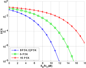
Bit-error rate curves for BPSK, QPSK, 8-PSK and 16-PSK, AWGN channel.

In a noisy channel, the BER is often expressed as a function of the normalized carrier-to-noise ratio measure denoted Eb/N0, (energy per bit to noise power spectral density ratio), or Es/N0 (energy per modulation symbol to noise spectral density).
For example, in the case of QPSK modulation and AWGN channel, the BER as function of the Eb/N0 is given by:
 .[2]
.[2]
People usually plot the BER curves to describe the performance of a digital communication system. In optical communication, BER(dB) vs. Received Power(dBm) is usually used; while in wireless communication, BER(dB) vs. SNR(dB) is used.
Measuring the bit error ratio helps people choose the appropriate forward error correction codes. Since most such codes correct only bit-flips, but not bit-insertions or bit-deletions, the Hamming distance metric is the appropriate way to measure the number of bit errors. Many FEC coders also continuously measure the current BER.
A more general way of measuring the number of bit errors is the Levenshtein distance.
The Levenshtein distance measurement is more appropriate for measuring raw channel performance before frame synchronization, and when using error correction codes designed to correct bit-insertions and bit-deletions, such as Marker Codes and Watermark Codes.[3]
Mathematical draft[edit]
The BER is the likelihood of a bit misinterpretation due to electrical noise  . Considering a bipolar NRZ transmission, we have
 for a «1» and
  for a «0». Each of
  and
and  has a period of
  .
.
Knowing that the noise has a bilateral spectral density  ,
,
is 
and is  .
.
Returning to BER, we have the likelihood of a bit misinterpretation  .
.
 and
and 
where  is the threshold of decision, set to 0 when
  .
.
We can use the average energy of the signal  to find the final expression :

±§
Bit error rate test[edit]
BERT or bit error rate test is a testing method for digital communication circuits that uses predetermined stress patterns consisting of a sequence of logical ones and zeros generated by a test pattern generator.
A BERT typically consists of a test pattern generator and a receiver that can be set to the same pattern. They can be used in pairs, with one at either end of a transmission link, or singularly at one end with a loopback at the remote end. BERTs are typically stand-alone specialised instruments, but can be personal computer–based. In use, the number of errors, if any, are counted and presented as a ratio such as 1 in 1,000,000, or 1 in 1e06.
Common types of BERT stress patterns[edit]
- PRBS (pseudorandom binary sequence) – A pseudorandom binary sequencer of N Bits. These pattern sequences are used to measure jitter and eye mask of TX-Data in electrical and optical data links.
- QRSS (quasi random signal source) – A pseudorandom binary sequencer which generates every combination of a 20-bit word, repeats every 1,048,575 words, and suppresses consecutive zeros to no more than 14. It contains high-density sequences, low-density sequences, and sequences that change from low to high and vice versa. This pattern is also the standard pattern used to measure jitter.
- 3 in 24 – Pattern contains the longest string of consecutive zeros (15) with the lowest ones density (12.5%). This pattern simultaneously stresses minimum ones density and the maximum number of consecutive zeros. The D4 frame format of 3 in 24 may cause a D4 yellow alarm for frame circuits depending on the alignment of one bits to a frame.
- 1:7 – Also referred to as 1 in 8. It has only a single one in an eight-bit repeating sequence. This pattern stresses the minimum ones density of 12.5% and should be used when testing facilities set for B8ZS coding as the 3 in 24 pattern increases to 29.5% when converted to B8ZS.
- Min/max – Pattern rapid sequence changes from low density to high density. Most useful when stressing the repeater’s ALBO feature.
- All ones (or mark) – A pattern composed of ones only. This pattern causes the repeater to consume the maximum amount of power. If DC to the repeater is regulated properly, the repeater will have no trouble transmitting the long ones sequence. This pattern should be used when measuring span power regulation. An unframed all ones pattern is used to indicate an AIS (also known as a blue alarm).
- All zeros – A pattern composed of zeros only. It is effective in finding equipment misoptioned for AMI, such as fiber/radio multiplex low-speed inputs.
- Alternating 0s and 1s — A pattern composed of alternating ones and zeroes.
- 2 in 8 – Pattern contains a maximum of four consecutive zeros. It will not invoke a B8ZS sequence because eight consecutive zeros are required to cause a B8ZS substitution. The pattern is effective in finding equipment misoptioned for B8ZS.
- Bridgetap — Bridge taps within a span can be detected by employing a number of test patterns with a variety of ones and zeros densities. This test generates 21 test patterns and runs for 15 minutes. If a signal error occurs, the span may have one or more bridge taps. This pattern is only effective for T1 spans that transmit the signal raw. Modulation used in HDSL spans negates the bridgetap patterns’ ability to uncover bridge taps.
- Multipat — This test generates five commonly used test patterns to allow DS1 span testing without having to select each test pattern individually. Patterns are: all ones, 1:7, 2 in 8, 3 in 24, and QRSS.
- T1-DALY and 55 OCTET — Each of these patterns contain fifty-five (55), eight bit octets of data in a sequence that changes rapidly between low and high density. These patterns are used primarily to stress the ALBO and equalizer circuitry but they will also stress timing recovery. 55 OCTET has fifteen (15) consecutive zeroes and can only be used unframed without violating one’s density requirements. For framed signals, the T1-DALY pattern should be used. Both patterns will force a B8ZS code in circuits optioned for B8ZS.
Bit error rate tester[edit]
A bit error rate tester (BERT), also known as a «bit error ratio tester»[4] or bit error rate test solution (BERTs) is electronic test equipment used to test the quality of signal transmission of single components or complete systems.
The main building blocks of a BERT are:
- Pattern generator, which transmits a defined test pattern to the DUT or test system
- Error detector connected to the DUT or test system, to count the errors generated by the DUT or test system
- Clock signal generator to synchronize the pattern generator and the error detector
- Digital communication analyser is optional to display the transmitted or received signal
- Electrical-optical converter and optical-electrical converter for testing optical communication signals
See also[edit]
- Burst error
- Error correction code
- Errored second
- Pseudo bit error ratio
- Viterbi Error Rate
References[edit]
- ^ Jit Lim (14 December 2010). «Is BER the bit error ratio or the bit error rate?». EDN. Retrieved 2015-02-16.
- ^
Digital Communications, John Proakis, Massoud Salehi, McGraw-Hill Education, Nov 6, 2007 - ^
«Keyboards and Covert Channels»
by Gaurav Shah, Andres Molina, and Matt Blaze (2006?) - ^ «Bit Error Rate Testing: BER Test BERT » Electronics Notes». www.electronics-notes.com. Retrieved 2020-04-11.
![]() This article incorporates public domain material from Federal Standard 1037C. General Services Administration. (in support of MIL-STD-188).
This article incorporates public domain material from Federal Standard 1037C. General Services Administration. (in support of MIL-STD-188).
External links[edit]
- QPSK BER for AWGN channel – online experiment
Качество сетей передачи данных. Транспорт
Время прочтения
8 мин
Просмотры 28K

В предыдущей статье были затронуты базовые метрики качества сетей и систем передачи данных. Также было обещано написать про то, как все работает изнутри. И намеренно не было упомянуто про качество среды передачи данных и ее характеристиках. Надеюсь, что новая статья даст ответы на эти вопросы.
Среда передачи
Начну, пожалуй, с последнего пункта — качества среды передачи. Как уже написано выше, про нее ничего не говорилось в предыдущем повествовании, поскольку само по себе количество сред и их характеристики очень сильно различаются и зависят от просто колоссального множества факторов. Разбираться во всем этом многообразии задача соответствующих специалистов. Всем очевидно использование радио-эфира в качестве среды передачи данных. Я же помню в конце 90-х начале 00-х особой популярностью у операторов связи стали пользоваться такие экзотические способы передачи, как лазерные атмосферные передатчики.  Выглядели они, в зависимости от производителя и конфигурации примерно как на картинке слева (да, почти такой себе светотелефон из радиолюбительского детства). Преимущество их было в том, что не надо было получать разрешение ГРКЧ, да и скорости, по сравнению с радиомостом были несколько больше, кроме того существовали модификации для организации каналов с временным разделением (E1 и т.п.), а подобное оборудование радио-доступа стоило непомерно дорого. Почему не оптический кабель? Потому что в те счастливые времена дикого провайдинга оптика еще была довольно дорогой, а за конвертер интерфейса или активное оборудование, способное принять оптический линк напрямую давали небольшой (а кто-то и большой) брусок золота. Были еще спутниковые каналы, но это вообще из области фантастики и позволить их себе могли разве что компании нефтяного сектора и прочего национального благосостояния. Но работа канала через спутник сводится к использованию радио-эфира, со всеми вытекающими и внесением огромной задержки.
Соответственно погружаясь в вопрос в результате будем иметь множество сред и ни одной обобщенной характеристики. Тем не менее для нас среда это всего лишь транспорт, передающий информацию из точки А в точку Б. А для транспорта (даже общественного) характеристикой отражающей его качество будет доставка всех битов (ну или пассажиров) без искажений и потерь (не хотелось бы лишиться части тела при перевозке, согласитесь). Т.е. мы приходим к такой обобщенной метрике качества транспорта как количество битовых ошибок, или BER (Bit error rate). В чисто пакетных сетях она практически не используется, поскольку ошибки передачи выявляются на уровне пакета, например подсчетом контрольных сумм: FCS (Frame check sequence) для L2 или сhecksum IP для L3. Если контрольная сумма не совпадает, то пакет целиком отбрасывается как невалидный. Если же рассмотреть гетерогенные сети, те в которых транспортом может служить непакетная сеть, а, например, один из вариантов описанных выше, либо вообще используется транзит через ATM, PDH, SDH и подобное без непосредственной (но с восстановлением) передачи пакета, то битовые ошибки транспорта могут значительно влиять, конечно в зависимости от технологии. Рассмотрим инкапсуляцию и передачу Ethernet-фрейма в HDLC. Другие технологии используют практически такую же технику.

Схема читается слева-направо (взята здесь).
- Какой-то узел сети А отправляет пакет в сторону какого-то узла сети Б
- Транспорт между сетями построен на сети PDH
- Узел на границе выхода сети А вырезает из Ethernet-фрейма область полезной нагрузки (поля от DestinationAddress до FCS включительно), оборачивает в HDLC заголовки, и отправляет на граничный узел входа сети Б
- Граничный узел входа сети Б выделяет область полезной нагрузки и восстанавливает Ethernet-фрейм
- Фрейм с граничного узла отправляется получателю
Как можно видеть, в данном случае контрольная передается корректно и в случае повреждения битового потока в процессе передачи восстановленный пакет с неверной FCS будет отброшен получателем. В данном случае механизм обнаружения ошибки налицо.
Но не всегда используется надстройка инкапсуляции, либо передается вообще не полноценный фрейм, а лишь поле payload. Т.е. вырезается область, оборачивается во внутренний протокол, а на другой стороне восстанавливаются недостающие данные, включая отсутствующие заголовки L2. Соответственно пропадает и FCS — она просто рассчитывается заново. Таким образом получается, если данные были повреждены, а FCS рассчитан на основании “испорченных” данных, то получатель принимает совсем не тот пакет, который ему отправляли. Это довольно часто встречается в спутниковой связи, чтобы повысить полезную утилизацию канала, избегая передачи условно “лишней” информации. Резюмируя, получается что метрика BER может быть интересна в случаях когда:
- необходимо проверить стабильность физического канала, например для оптики это 10E-12 (упоминается в IEEE802.3)
- Ethernet-фреймы упаковывают в SDH(GFP), PDH, ATM и другие транспортные сети.
- используются технологии xHSL, PPP протоколы в которые упаковывают IP пакеты
BER тест
Метрика известна — это отношение количество битовых ошибок к общему числу переданных битов. Методика измерения для сетей TDM известна как спецификация ITU-T G.821. Классически для проверки каналов используется BERT (BER Test) первого уровня, но с учетом специфики работы протоколов инкапсуляции пакетных сетей и самого принципа работы пакетных сетей необходимо иметь возможность проводить тесты на L1-L4. Немного далее будет рассмотрено подробнее. Ну а сейчас следует определиться что проверять и как проверять. На вопрос:” Что проверять?” Отвечает ITU-T 0.150. В его пункте 5 рассмотрены типы ПСП (псевдослучайных последовательностей), из которых просто берутся данные для формирования пакета. Т.е. нужно просто взять и заполнить соответствующий уровень пакета данными выбранной ПСП. У нас в приборах используются следующие ПСП:
- ПСП 2е9 (ITU-T 0.150 пункт 5.1)
- ПСП 2е11 (ITU-T 0.150 пункт 5.2)
- ПСП 2е15 (ITU-T 0.150 пункт 5.3)
- ПСП 2е23 (ITU-T 0.150 пункт 5.6)
- ПСП 2е31 (ITU-T 0.150 пункт 5.8)
- пользовательская последовательность (32 бита)
- все нули
- все единицы
- альтернативная последовательность (01010101)
Пользовательская последовательность введена для совместимости с приборами, которые существуют на рынке, т.е можно задать любую последовательность и проводить совместный тест.
Вопрос как проверять пока что открыт, попробуем разобраться. Допустим мы умеем генерировать определенные пакеты. Если отправить такой пакет на другой конец транспорта, то как понять, что он не изменился (следует абстрагироваться от пакетного принципа, поскольку у нас может не быть FCS и других типов контроля, как описано ранее)? Самый простой вариант — завернуть пакет обратно (в TDM называется “сделать петлю”, в Ethernet — установить шлейф). Заворот, во многих случаях, можно сделать на выходе канала без изменения среды передачи, т.е. реально поставить петлю на выходе E1 и все будет работать. Но т.к. данные проделывают двойной путь, то вероятность возникновения ошибки также возрастает в 2 раза. Да и каналы могут быть асимметричными или однонаправленными. Соответственно идеальным было бы иметь возможность обладать информацией о корректном следовании и сравнивать приходящие пакеты с уже известной информацией. Первый, и наиболее простой вариант, применимый когда оба выхода канала располагаются рядом (например такое возможно при TDM коммутации, или тестировании оптического “кольца”) заключается в том, что один порт прибора генерирует тестовый трафик, а другой порт этого же прибора его получает и сравнивает, а т.к. сравнение происходит в том же узле, что и генерация, то проблем со сравнением данных последовательности не возникает. Второй вариант предполагает восстановление первоначальной последовательности и сравнение ее с приходящими данными. В случае с полностью случайной последовательностью реализовать такое не представляется возможным, а вот если последовательность псевдослучайная, то вполне. Какое-то время затрачивается на синхронизацию в самом начале теста, но затем сравнение не представляет сложности. Поскольку ПСП первого прибора и ПСП второго известны и одинаковы, синхронизация сводится к поиску места начала сравнения в ПСП второго прибора. Таким образом существуют следующие топологии:
- «сам на себя» 1 — один прибор на одном порту, на другом конце транспорта стоит шлейф
- «сам на себя» 2 — один прибор с одного порта своего порта на другой свой порт
- с одного прибора на другой прибор, с синхронизацией
Еще раз стоит отметить, что тест BER не рекомендуется использовать на сетях лишь с пакетной коммутацией. Приведу пример. Допустим, уже идет тестовый поток и приборы синхронизированы (топология 3). В какой-то момент времени происходит следующее:
- формируется Ethernet-фрейм, содержащий данные ПСП
- для такого фрейма рассчитывается FCS и он укладывается в выходной буфер
- фрейм отправляется по сети на другой прибор
- по каким-то причинам происходит изменение всего одного бита внутри пакета
- получатель принимает пакет
- FCS принятого пакета не соответствует содержимому
- пакет отбрасывается (если между отправителем и получателем есть, например, коммутатор, то “кривой” пакет вообще не дойдет до получателя, т.к. будет уничтожен до него)
- отправитель формирует следующий пакет (все начинается с п.1)
В приведенном примере на шаге 8 произойдет срыв синхронизации на стороне получателя. Произойдет это потому, что отправитель возьмет следующий блок ПСП, а получатель будет сравнивать с тем блоком, который потерялся в предыдущем цикле (он ведь ничего не знает о потере). Срыв синхронизации приведет к необоснованно большому росту битовых ошибок, т.к. все вновь идущие блоки абсолютно не совпадают, что приведет к тому, что за один пакет число битовых ошибок будет увеличиваться на размер фрейма. Через какое-то время будет предпринята попытка восстановления синхронизации, но количество накопленных битовых ошибок будет сильно не соответствовать действительности.
А как в железе?
Как у других не знаю, но у наших приборов Беркут (ET, ETX, ETL, B100, а также модуль B5-GBE для MMT) дела обстоят следующим образом. Помня принцип о генерации и анализе трафика как можно ближе к физическому сегменту из первой статьи, все подобные задачи были возложены на FPGA. Упрощенная структурная схема выглядит так:
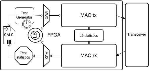
MAC ядро представлено двумя блоками: один на прием, другой на передачу. Это позволяет независимо принимать и отправлять пакеты, т.е. нет взаимовлияния очереди отправки на очередь приема и наоборот. Также с двух независимых блоков возможно вести общую статистику по полученному и отправленному трафику независимо от типа теста. Данные с блока передачи поступают на трансмиттер и отправляются в сеть, а входящие данные с трансивера поступают в блок приема.
Поскольку для некоторых топологий тестов необходим функционал шлейфа (loopback, петля), то он реализован отдельным блоком. Возможно установить шлейф уровня L1-L4:
- L1 — просто заворачивает трафик обратно (происходит это еще в трансивере)
- L2 — меняет DstMAC<->SrcMAC местами, пересчитывает FCS
- L3 — меняет DstMAC<->SrcMAC и DstIP<->SrcIP местами, пересчитывает FCS
- L4 — меняет DstMAC<->SrcMAC, DstIP<->SrcIP и DstPort<->SrcPort, пересчитывает FCS
Статистика по пакетам ведется и для режима шлейфа тоже, что позволяет грубо оценить соотношение отправленных и принятых пакетов.
Модуль генератора для каждого типа теста свой, для BERT он содержит генератор ПСП всех заявленных типов.
Работает это следующим образом. От генератора ПСП поступают данные на мультиплексор (проще говоря коммутатор), который, если не включен какой-то другой канал в данный момент, направляет поток в MAC tx модуль. MAC tx модуль, в соответствии с настройками теста (уровень BERT, размер пакета, данные полей) формирует из ПСП валидный Ethernet-фрейм и отправляет его в трансивер, который в свою очередь отправляет его в сеть. В зависимости от топологии теста фрейм либо заворачивается удаленной стороной, либо анализируется. В любом случае первичная обработка пакета не отличается. Фрейм попадает на MAC rx ядро, которое отправляет его на мультиплексор. Мультиплексор в зависимости от режима работы прибора направляет пакет либо в Loopback модуль, откуда после обработки он сразу же направляется в MAC tx для отправки, либо в модуль обработки и статистики теста, где, если потребуется, будет проведена попытка синхронизации ПСП и выполнено сравнение исходной последовательности с полученной. Результаты обработки отдаются в модуль вывода статистики.
Использование FPGA или ASIC позволяет все операции проводить параллельно, что не вносит какие либо задержки на обработку и исключает взаимовлияние модулей обработки.
Заключение
Несмотря на всю кажущуюся простоту алгоритмов и методик, за ними стоит много лет серьезных исследований. Огромное число факторов до сих пор влияет как на точность измерений, так и на стоимость приборов (прецизионные элементы, высокоскоростные ПЛИС). Например, приведенный выше BER тест не отличается значительной сложностью в общем алгоритмическом плане, но требует знаний в области математики, информатики и теории информации для разработки жизнеспособной модели. Модификация BER теста для пакетных сетей (поддержка уровней L2-L4) требует глубокого понимания принципов коммутации и маршрутизации. Надеюсь, что подобного рода статьи интересны и приносят пользу. В следующих публикациях планирую написать про сертифицированные тесты, генераторы трафика, фильтры и аналитические комплексы. Ведь как сказал Джон Фицджеральд Кеннеди на выступлении перед гражданами США перед стартом Лунной программы:
“И мы сделаем это. Не потому, что это легко, а потому что трудно.”
PS. Задавайте вопросы и предлагайте темы, в рамках нашей компетенции готовы на все 
Most modern Ethernet variants are designed for a bit error ratio (BER) of 10-12 or better. Early variants only had 10-10 or better, see IEEE 802.3 for details.
In term of packets/frames, it depends on their average size. A maximum sized, untagged Ethernet frame requires 1526 bytes or 12,208 bits on the wire, so a BER of 10-12 roughly translates to a frame error ratio of 1.2×10⁻⁷. That’s worst case, within specs — with decent, not maxed-out cabling, you’re usually quite a bit better, like 10-9 or so. The 4.83×10⁻³ frame error rate you’ve measured is very high — depending on the exact purpose of that cable you’d have to decide whether you can live with it or not.
However: if you fabricate your own cables you need to use a tester than can certify the cable ($1000+). Effectively, that Pockethernet tester of yours can only measure the error rate for a certain protocol. It doesn’t measure attenuation over the frequency range, the crosstalk varieties or the various other parameters.
It’s not enough to try-and-error because you might want to run other protocols on your cables later on — a Cat-5e DIY cable that’s running 1000BASE-T fine might give up on 2.5GBASE-T since that uses a larger frequency envelope. Certified cables are guaranteed to work in all specified scenarios.
 This article will be rather short in comparison with the others in the mini-series about various Ethernet/IP testing methods but it is one that is necessary as Bit Error Tests have a long tradition in telco environment (circuit based networks) but are still quite valid even in nowadays packet networks – at least for some specific cases. So without further delay let start with some theory behind the testing and some practical use followed by some use cases and best practices.
BERT introduction
As you can guess from the name this test is really to test physical layer traffic for any anomalies. This is a result from the test origins where T1/E1 circuits have been tested and each bit in each time-slot mattered as the providers were using those up to the limit as bandwidth was scarce. Also as most of the data being transferred were voice calls any pattern alterations had quite serious implications on the quality of service. This also led to the (in)famous reliability of five nines or the 99.999% which basically states that the link/device must be available 99.999% throughout a specified SLA period (normally a month or a year). One must remember that redundancy was rather rare so the requirements for hardware reliability was really high. But by the move away from the circuit-based TDM networks towards the packet-based IP networks the requirements changed. The bandwidth is now in abundance in most places and the wide deployment of advanced Ethernet and IP feature rich devices provides with plenty options for redundancy and QoS with packet-switched voice traffic on rise – one would think it is not really necessary to consider BERT as something one should use as test method but that would be huge mistake.
Why BERT
There are few considerations that can make BERT an interesting choice. I will list some I think are the most interesting.
- It has been designed to run for extended period of time which makes it ideal for acceptance testing which is still often required
- BERT is ideal for testing jitter as it was one of the primary design goals
- The different patters used in BERT can be used for packet optimization testing (I will discuss this later in more detail)
- Most of the BERT tests are smarter than just counting bit errors so the test can be used for other testing
BERT Physical setup and considerations
On Ethernet network you cannot run a simple L1 test unless you test just a piece of cable or potentially a hub as all other devices would require some address processing. This makes the test being different on Ethernet network from unframed E1 as unlike on E1 we need to set framing to Ethernet with the source and destination defined on the tester. Also as Ethernet must be looped on a logical level it is not possible to use simple RJ45 with pair of wires going from TX to RX as you could with E1 and either hardware or software loopback reflector is required. Most tester will actually allow you to specify even layer 3 and 4 for IP addresses and UDP ports. The reason is usually so the management traffic between tester and loopbacks can use this channel for internal communication.
Pattern selection options
As this test originates from the telco industry some interesting options are usually presented on the testers. The stream can generate these patterns:
- All zeros or all ones – which are specific patters originated from TDM environment
- 0101 pattern and 1010 pattern – patterns that can be easily compressed
- PRBS – Pseudo Random Bit Sequence – is an deterministic sequence that cannot be compressed/optimized the details and calculation can be found on wikipedia
- Inverted PRBS – the same as above but the calculation function is inversed to counter any “optimization” for the PRBS
The thing to remember is that PRBS will be applied to the payload of the frame/packet/datagram so it there is any sort of optimization present it will have no effect as PRBS is by design not compressible. There are various “strengths” of the pseudo-random pattern the higher the number the less repeating it will include. Normally it is possible to see two main variants: 2^15 which is 32,767 bits long and 2^23 which 8,388,607 bits long. Obviously the longer the pattern the better and more “random” behavior it emulates.
Error injecting Options
As this test originated in telco world injecting errors was a major thing but in Ethernet network it lost its importance. If you inject even a single bit error in an Ethernet frame the CRC should be incorrect and the whole frame should be dropped on first L2 equipment it will be passed through which should always result in alarm LoF(Loss of Frame)/LoP (Loss of Pattern).
Use cases, Best Practices and Conclusion
The most common use case for BERT in nowadays network would be in commissioning new links as you can run a fairly simple test for a long time that will give you a reasonable idea bout it’s quality in terms of frames drops and jitter.
The few recommendations about how to run this test would be as follows:
- Use the largest pattern you can.
- Remember that the line rate and L2 rates will be different because of the overheads.
- Remember that 99.999% of availability results in 0.8s outage in 24 hours (which can be quite a lot of frames)
- PRBS cannot be optimized
So as you can see BERT is rather simple and straight forward test that even though is in many ways deprecated by RFC2544 and others (like Y.156sam) it is still a very good test to know especially if you are in jitter sensitive environment e.g. where VoIP and IPTV is deployed.
Not all network engineers understand the impact of interface errors on TCP performance. Interface errors can cause a BIG impact, although it may not be intuitive at first glance.
We recently pointed out some interfaces with extremely high errors to a customer. We mentioned that the links with the highest percentage loss were likely getting very little useful data through them, and that they should investigate the cause of these errors. Initially the customer did not appear to be very concerned because the percent of errors was below 3%. We personally find error rates of greater than 0.001% to be a cause for concern.
Based on this experience, I thought I’d write up an article to illustrate the impact of interface errors.
Best TCP/IP Performance Expected
Perhaps the first question to consider is “What is the best TCP/IP performance you can expect on a Gigabit Ethernet link in the campus?”
First let’s look at the buffering required for TCP which is the bandwidth delay product (BDP). With a Gigabit Ethernet link, the buffering required in a receiving system for maximum performance is the amount of data that can be sent between ACKs. The bandwidth of a Gigabit link is 1000 Mbps. If the data exchange is inside a campus, say between a data center server and a user, the RTT should be very small, perhaps 2 milliseconds or .002 seconds. So for a Gigabit link, the receiving system needs to be able to buffer bandwidth * delay:
BDP = 1000 Mb/s * .002 seconds
BDP = 1000 Mb/s (1 byte/8 bits) * .002 seconds
BDP = 125,000,000 bytes * .002 seconds
BDP = 250,000 Bytes
When the BDP is less than the TCP window size, the path BW is the limiting factor in throughput. For a Gigabit Ethernet link, the BDP of 250,000 Bytes is greater than the default TCP window of 32,000 Bytes (the default TCP window size), so the path bandwidth will not be the limiting factor.
When the TCP window size is less than the buffering required to keep the pipe filled, the mechanics of TCP operation affect the maximum throughput. In this case, the sending system sends a full TCP window worth of data, waits for an acknowledgement from the receiver, then sends again. The application is not using the send-window mechanism that would allow TCP to fill the bandwidth pipe. Only when an ACK is received can more data can be sent. Therefore, the maximum throughput that can be achieved for a source and destination is the window size divided by the time it takes to get back an ACK (i.e., the round trip time). In this case, the best throughput you can achieve is the chunk size (amount of data sent per window) divided by the round trip time or
Max Throughput = chunk size / RTT
Max Throughput in bps = [Bytes * 8 (bits/byte) ] / RTT
Another question to consider is “What is the maximum throughput for a GE link in the data center?”
For this best case calculation, I assume the application sends a chunk of 64,000 Bytes of data across multiple TCP segments and waits for an ACK before sending more data. If the data exchange is inside a campus, say between a data center server and a user, the RTT should be very small, perhaps 2 milliseconds or .002 seconds. So the maximum rate for a single file transfer would be
64,000 * 8 / .002 =256,000,000 bps or 256 Mbps
Conclusion: If the RTT is 2ms, a maximum rate of about 256Mbps is possible in the campus across a Gigabit Ethernet link.
Expected TCP/IP Performance With Errors
A third question to consider is “What is the impact of errors on TCP/IP performance on a Gigabit Ethernet link in the campus?”
Note: There are several potential sources of interface errors, including interface discards when there is insufficient bandwidth to support the traffic volume, misconfigured duplex and speed settings, excessive buffering on interfaces, misconfigured EtherChannels, and faulty cables or hardware.
First we consider what is an acceptable error rate. Based on the IEEE 802.3ab standards, the Bit Error Rate (BER) considered acceptable for 1000BaseT circuits is 1 in 1*10^10 bits.
1 bit loss in 1*10^10 bits/sec = 1 bit loss in 1.25*10^9 bytes per second
If we assume an average packet is 1000 bytes long, the 1000BaseT BER would be 1 packet loss in 1.25*10^6 packets. On a percentage basis, 1 packet lost/1.25*10^6 = 8*10^-7 = .00008%
Therefore we could round this up and really expect to see at most .0001% packet loss on the Gigabit Ethernet cable.
Note: This is a very generous packet size, perhaps 300 to 450 bytes may be a more common average for enterprises including VoIP. However, the 1000 byte packet size was chosen for easier math.
However, the TCP path can experiences packet loss due to performance and configuration issues with the servers and network devices. TCP performance is degraded as packets are lost and need to be retransmitted. The Mathis equation is a formula that approximates the actual impact of loss on the maximum throughput rate:
Max Rate in bps < (MSS/RTT)*(1 / sqrt(p))
where
- MSS = maximum segment size in bytes
- RTT = round trip time in seconds
- p = the probability of packet loss
Note that this formula includes constant with a value that is approximately 1 that resolves the bytes to bits… The formula is known as the Mathis equation, from a 1997 paper titled The Macroscopic Behavior of the TCP Congestion Avoidance Algorithm.
Now we can apply the Mathis equation to the example GE link. For the MSS we will use 1460 bytes, since this will fit into one TCP packet (when the MTU of the network gear is 1500 bytes.) We assume that the application will send a chunk of 1460 Bytes of data and waits for an ACK before sending more data. Since this data exchange is inside the campus, we are again assuming that the RTT is.002 seconds. So the maximum rate will be for a single file transfer with standard BER for 1000BaseT cable of 0.0001% losses:
Mathis Max Rate in bps < (MSS/RTT)*(1 / sqrt(p))
Max rate in bps < (1460/.002)*(1/ sqrt(.000001))
Max rate in bps < 7.3*10^8 bps
Max rate in bps < 730 Mbps
The predicted Mathis rate exceeds the maximum rate of 256Mbps we calculated without losses, so the maximum rate will be the lesser of these two calculations or 256Mpbs. This result is reasonable, circuits that meet the acceptable BER for Gigabit Ethernet do not adversely impact TCP performance.
What happens at our threshold rate of concern? In this case, we have 0.001% losses, or 1 packet in 100,000.
Mathis Max Rate in bps < (MSS/RTT)*(1 / sqrt(p))
Max rate in bps < (1460/.002)*(1/ sqrt(.00001))
Max rate in bps < 2.3*10^8 bps
Max rate in bps < 231 Mbps
Since this is within 10% of the predicted 256Mbps, so we deem it as “acceptable.”
However, we then look at what happens if the line has 0.01% losses, or 1 lost packet in 10,0000 packets?
Mathis Max Rate in bps < (MSS/RTT)*(1 / sqrt(p))
Max rate in bps < (1460/.002)*(1/ sqrt(.0001))
Max rate in bps < 7.3*10^7 bps
Max rate in bps < 73 Mbps
This is significantly below the predicted 256Mbps. This reduced rate will cause a noticeable impact on application performance.
Looking back at the beginning of the article, what is the impact of less than 3% errors? If we use an error rate of 3%, the maximum throughput on the Gigabit Ethernet link is drastically reduced:
Mathis Max Rate in bps < (MSS/RTT)*(1 / sqrt(p))
Max rate in bps < (1460/.002)*(1/ sqrt(.02))
Max rate in bps < 4.2*10^6 bps
Max rate in bps < 4.2 Mbps
This drastically reduced rate could easily cause sluggish application performance.
Conclusion:
The following diagram illustrates the impact of interface errors on TCP throughput. We see that host-to-host system performance quickly degrades.

I believe that any interface error rates that exceed 0.01% should be a cause for alarm and immediate investigation/resolution. I hope this discussion helps explain why you should be very concerned about interface errors!
— cwr
_________________________________________________________________________________________
References on TCP Performance, Reliability, and the Mathis Equation
This article summarizes ideas from several sources of information:
- The Macroscopic Behavior of the TCP Congestion Avoidance Algorithm
- RFC 1323 – TCP Extensions for High Performance
- TCP/IP Performance Factors
- TCP Performance and the Mathis Equation
- Application Analysis Using TCP Retransmissions, Part 1
- Application Analysis Using TCP Retransmissions, Part 2
В цифровой передаче , количество битовых ошибок является количеством принятых бит одного потока данных над каналом связи , которые были изменены из — за шум , помехи , искажений или битой синхронизацию ошибок.
Коэффициент битовых ошибок ( BER ) — это количество битовых ошибок в единицу времени. Коэффициент битовых ошибок (также BER ) — это количество битовых ошибок, деленное на общее количество переданных битов за исследуемый интервал времени. Коэффициент битовых ошибок — это безразмерная мера производительности, часто выражаемая в процентах . [1]
Бита вероятность ошибка р е является ожидаемым значением коэффициента ошибок по битам. Коэффициент битовых ошибок можно рассматривать как приблизительную оценку вероятности битовых ошибок. Эта оценка точна для длительного интервала времени и большого количества битовых ошибок.
Пример
В качестве примера предположим, что эта переданная битовая последовательность:
0 1 1 0 0 0 1 0 1 1
и следующая полученная битовая последовательность:
0 0 1 0 1 0 1 0 0 1,
Количество битовых ошибок (подчеркнутые биты) в данном случае равно 3. BER — это 3 неверных бита, разделенных на 10 переданных битов, в результате чего BER составляет 0,3 или 30%.
Коэффициент ошибок пакета
Коэффициент ошибок пакетов (PER) — это количество неправильно принятых пакетов данных, деленное на общее количество принятых пакетов. Пакет объявляется некорректным, если хотя бы один бит ошибочен. Ожидаемое значение PER обозначается вероятностью ошибки пакета p p , которая для длины пакета данных N бит может быть выражена как
- ,
предполагая, что битовые ошибки не зависят друг от друга. Для малых вероятностей битовых ошибок и больших пакетов данных это примерно
Подобные измерения могут быть выполнены для передачи кадров , блоков или символов .
Факторы, влияющие на BER
В системе связи на BER на стороне приемника могут влиять шум канала передачи , помехи , искажения , проблемы битовой синхронизации , затухание , замирания из-за многолучевого распространения беспроводной связи и т. Д.
BER может быть улучшен путем выбора сильного уровня сигнала (если это не вызывает перекрестных помех и большего количества битовых ошибок), путем выбора медленной и надежной схемы модуляции или схемы линейного кодирования , а также путем применения схем канального кодирования , таких как избыточные коды прямого исправления ошибок. .
КОБ передачи является количество обнаруженных битов , которые являются неправильными до коррекции ошибок, разделенных на общее количество переданных битов ( в том числе избыточных кодов ошибок). Информация КОБ , примерно равна вероятности ошибки декодирования , это число декодированных битов , которые остаются неправильно после коррекции ошибок, деленное на общее число декодированных битов (полезная информация). Обычно BER передачи больше, чем BER информации. На информационный BER влияет сила кода прямого исправления ошибок.
Анализ BER
BER можно оценить с помощью стохастического ( Монте-Карло ) компьютерного моделирования. Если предполагается простая модель канала передачи и модель источника данных , BER также может быть вычислен аналитически. Примером такой модели источника данных является источник Бернулли .
Примеры простых моделей каналов, используемых в теории информации :
- Двоичный симметричный канал (используется при анализе вероятности ошибки декодирования в случае непакетных битовых ошибок в канале передачи)
- Канал аддитивного белого гауссова шума (AWGN) без замирания.
Наихудший сценарий — это полностью случайный канал, в котором шум полностью преобладает над полезным сигналом. Это приводит к BER передачи 50% (при условии, что предполагается источник двоичных данных Бернулли и двоичный симметричный канал, см. Ниже).


В канале с шумом BER часто выражается как функция нормированного показателя отношения несущей к шуму, обозначаемого Eb / N0 (отношение энергии на бит к спектральной плотности мощности шума) или Es / N0 (энергия на символ модуляции для спектральная плотность шума).
Например, в случае модуляции QPSK и канала AWGN, BER как функция Eb / N0 определяется следующим образом:
. [2]
Люди обычно строят кривые BER для описания производительности цифровой системы связи. В оптической связи обычно используется зависимость BER (дБ) от принимаемой мощности (дБм); в то время как в беспроводной связи используется BER (дБ) по сравнению с SNR (дБ).
Измерение коэффициента ошибок по битам помогает людям выбрать подходящие коды прямого исправления ошибок. Поскольку большинство таких кодов исправляют только перевороты битов, но не вставки или удаления битов, метрика расстояния Хэмминга является подходящим способом измерения количества битовых ошибок. Многие кодеры FEC также непрерывно измеряют текущий BER.
Более общий способ измерения количества битовых ошибок — это расстояние Левенштейна . Измерение расстояния Левенштейна больше подходит для измерения характеристик сырого канала перед кадровой синхронизацией , а также при использовании кодов коррекции ошибок, предназначенных для исправления вставки и удаления битов, таких как коды маркеров и коды водяных знаков. [3]
Математический черновик
BER — это вероятность неправильной интерпретации из-за электрического шума. . Рассматривая биполярную передачу NRZ, мы имеем
для «1» и за «0». Каждый из а также имеет период .
Зная, что шум имеет двустороннюю спектральную плотность ,
является
а также является .
Возвращаясь к BER, мы можем немного неверно истолковать .
а также
куда — порог принятия решения, установленный в 0, когда .
Мы можем использовать среднюю энергию сигнала чтобы найти окончательное выражение:
± §
Проверка коэффициента битовых ошибок
BERT или тест частоты ошибок по битам — это метод тестирования цифровых схем связи, в котором используются заранее определенные шаблоны нагрузки, состоящие из последовательности логических единиц и нулей, сгенерированных генератором тестовых шаблонов.
BERT обычно состоит из генератора тестовых шаблонов и приемника, который может быть настроен на один и тот же шаблон. Их можно использовать парами, по одному на любом конце линии передачи, или по отдельности на одном конце с кольцевой проверкой на удаленном конце. BERT обычно представляют собой автономные специализированные инструменты, но могут быть основаны на персональном компьютере . При использовании количество ошибок, если таковые имеются, подсчитывается и представляется в виде отношения, например 1 на 1 000 000 или 1 на 1e06.
Распространенные типы паттернов стресса BERT
- PRBS ( псевдослучайная двоичная последовательность ) — псевдослучайный двоичный секвенсор из N бит. Эти последовательности шаблонов используются для измерения джиттера и глаз-маски TX-данных в электрических и оптических каналах передачи данных.
- QRSS (квазислучайный источник сигнала) — псевдослучайный двоичный секвенсор, который генерирует каждую комбинацию 20-битного слова, повторяет каждые 1048 575 слов и подавляет последовательные нули не более чем до 14. Он содержит последовательности с высокой плотностью, последовательности с низкой плотностью, и последовательности, которые меняются от низкого к высокому и наоборот. Этот шаблон также является стандартным шаблоном, используемым для измерения джиттера.
- 3 из 24 — шаблон содержит самую длинную строку последовательных нулей (15) с самой низкой плотностью (12,5%). Этот шаблон одновременно подчеркивает минимальную плотность единиц и максимальное количество последовательных нулей. Формат кадра D4 3 из 24 может вызвать желтый аварийный сигнал D4 для цепей кадра в зависимости от выравнивания одного бита с кадром.
- 1: 7 — Также упоминается как 1 из 8 . Он имеет только один в восьмибитной повторяющейся последовательности. Этот шаблон подчеркивает минимальную плотность 12,5% и должен использоваться при тестировании средств, установленных для кодирования B8ZS, поскольку шаблон 3 из 24 увеличивается до 29,5% при преобразовании в B8ZS.
- Мин. / Макс. — последовательность быстрого перехода узора с низкой плотности на высокую. Наиболее полезно при усилении функции ALBO ретранслятора .
- Все единицы (или отметка) — шаблон, состоящий только из единиц. Этот шаблон заставляет повторитель потреблять максимальное количество энергии. Если постоянный ток к ретранслятору отрегулирован должным образом, ретранслятор не будет иметь проблем с передачей длинной последовательности. Этот образец следует использовать при измерении регулирования мощности диапазона. Шаблон «все единицы без рамки» используется для обозначения AIS (также известного как синий сигнал тревоги ).
- Все нули — шаблон, состоящий только из нулей. Это эффективно при поиске оборудования, неправильно настроенного для AMI , такого как низкоскоростные входы мультиплексного волокна / радио.
- Чередование нулей и единиц — шаблон, состоящий из чередующихся единиц и нулей.
- 2 из 8 — шаблон содержит не более четырех последовательных нулей. Он не вызовет последовательность B8ZS, потому что для подстановки B8ZS требуется восемь последовательных нулей. Этот шаблон эффективен при поиске оборудования, не использованного для B8ZS.
- Bridgetap — разветвления моста в пределах пролета можно обнаружить с помощью ряда тестовых шаблонов с различной плотностью единиц и нулей. Этот тест генерирует 21 тестовую таблицу и длится 15 минут. Если возникает ошибка сигнала, на участке может быть один или несколько ответвлений моста. Этот шаблон эффективен только для участков T1, которые передают необработанный сигнал. Модуляция, используемая в пролетах HDSL, сводит на нет способность шаблонов моста обнаруживать ответвления моста.
- Multipat — этот тест генерирует пять часто используемых тестовых шаблонов, позволяющих проводить тестирование диапазона DS1 без необходимости выбирать каждый тестовый шаблон отдельно. Шаблоны: все единицы, 1: 7, 2 из 8, 3 из 24 и QRSS.
- T1-DALY и 55 OCTET — Каждый из этих шаблонов содержит пятьдесят пять (55) восьмибитовых октетов данных в последовательности, которая быстро изменяется между низкой и высокой плотностью. Эти паттерны используются в первую очередь для нагрузки на схему ALBO и эквалайзера, но они также усиливают восстановление синхронизации. 55 OCTET имеет пятнадцать (15) последовательных нулей и может использоваться только без рамки без нарушения требований к плотности. Для сигналов с фреймами следует использовать шаблон T1-DALY. Оба шаблона вызовут код B8ZS в схемах с опцией для B8ZS.
Тестер коэффициента битовых ошибок
Тестер коэффициента ошибок по битам (BERT), также известный как «тестер коэффициента ошибок по битам» [4] или решение для тестирования коэффициента ошибок по битам (BERT), представляет собой электронное испытательное оборудование, используемое для проверки качества передачи сигнала отдельных компонентов или целых систем.
Основные строительные блоки BERT:
- Генератор шаблонов , который передает определенный тестовый шаблон в ИУ или тестовую систему.
- Детектор ошибок, подключенный к DUT или тестовой системе, для подсчета ошибок, генерируемых DUT или тестовой системой.
- Генератор тактовых сигналов для синхронизации генератора шаблонов и детектора ошибок
- Анализатор цифровой связи не является обязательным для отображения переданного или принятого сигнала.
- Электрооптический преобразователь и оптико-электрический преобразователь для проверки сигналов оптической связи.
См. Также
- Пакетная ошибка
- Код исправления ошибок
- Секунда с ошибками
- Частота ошибок Витерби
Ссылки
- ^ Джит Лим (14 декабря 2010). «Является ли BER коэффициентом ошибок по битам или коэффициентом ошибок по битам?» . EDN . Проверено 16 февраля 2015 .
- ^
Digital Communications, Джон Proakis Масуд Салехи, McGraw-Hill Образование, ноябрь 6, 2007 - ^ «Клавиатуры и скрытые каналы»
Гауравом Шахом, Андресом Молиной и Мэттом Блейзом (2006?)
- ^ «Тестирование частоты ошибок по битам: Тест BER BERT» Электроника » . www.electronics-notes.com . Проверено 11 апреля 2020 .
![]() Эта статья включает материалы, являющиеся общественным достоянием, из документа Управления общих служб : «Федеральный стандарт 1037C» .(в поддержку MIL-STD-188 )
Эта статья включает материалы, являющиеся общественным достоянием, из документа Управления общих служб : «Федеральный стандарт 1037C» .(в поддержку MIL-STD-188 )
Внешние ссылки
- QPSK BER для канала AWGN — онлайн-эксперимент

Performance of the transmission system is of crucial importance to communication quality of the whole communication network. Good performance can be achieved through proper control over Bit Error Rate & BERT. The major factors affecting the performance of SDH transmission network includes bit error, jitter and wander.
So, what are the Bit Errors? Why are they so important to control? Do the Bit errors affect my network performance?
These are some of the questions that every network engineer and optical transmission engineer must know. Let’s dissect these questions & their answers one by one.
“Bit Error is the amount of interference and interruptions in reception”. Therefore, bit errors are important for two major reasons. Firstly, it is a key parameter to assess systems that transmit digital data from one location to another. Secondly, it is the error of a single number between receiving and sending data signals.
Why Bit Error Rate & BERT Testing is so crucial?
BER is crucial for Ethernet, Gigabit Ethernet, Optical fiber systems and Radio links. The basis of BER are same in all of these systems with minor differences. Therefore, a good knowledge of the Bit Error Rate also enables us to adjust other features of the link like power and bandwidth. BER is important to consider in design & operation for any system that transmits data over a network of some form where noise, interference and phase jitter may cause degradation of the digital signal.
Generation and Distribution of Bit Error Rate & BERT
Bit errors are a great harm to IP networks & transmission system because they lower the system stability. Bit errors fall into two major categories in terms of network performance.
1. Bit errors due to internal mechanism
Various noise sources, jitter, multiplexer, cross-connection systems and inter-symbol interference causes this type of bit errors. Long term error performance of the system judges this type of error.
2. Bit errors due to pulse interference
Electromagnetic interference, equipment fault and transient interference of power supply generates this kind of bit errors. This kind of bit errors usually occurs to the system abruptly in large amount. Long term error performance of the system judges this type of error.
ITU-T Standards for Bit Error Rate & BERT
Below are relevant ITU-T recommendations related to Bit Errors, control, design & specifications:
G.828
It specifies Bit Error performance event, parameter and indices of CBR (international Constant Bit Rate) synchronous digital channel. Therefore, it is applicable to lower order and higher order paths borne by VC-n and VC-n-Xc. The difference from G.826 is that its index is more strict than that of G.826.
G.826
It specifies high bit rate channel Bit Error performance parameter, on the basis of block.
G.821
It specifies the Bit Error performance parameter connected with 64k bps, on the basis of bit.
In conclusion, the working principle of BER assessment is a bit different from other forms of assessment. BER method assesses the full end to end performance of a system. This includes the transmitter, receiver and the medium between the two. In this way, bit error rate, BER enables the actual performance of a system in operation to be tested. Additionally, Bit errors optimization is critical for stable network operations. To understand the Bit Errors in deep, we need a solid grip on factors that control BER, BER Events, Reporting Points of BER and Testing.
How to calculate Bit Error Rate (& BERT)?
Bit Error Rate can be simply calculated using below formula:

Conventional error performance measurement is to measure the error performance of end-to-end connected digital reference circuit of 64kbit/s channel for the whole 27500km distance based on the error conditions of the bits. As the transmission rate of the transmission network is increasing, measurement of system error performance with bit as the unit shows its limitation.
Bit Error Rate & BERT Availability Parameters
Unavailable time
When the BER of the digital signals in any transmission direction of the transmission system is inferior to 10^3 in every second of consecutive 10 seconds, the system will be considered as entering into the unavailable time since the first of the 10 seconds.
Available time
When the BER of the digital signals is better than 10^3, in every second of consecutive 10 seconds, the system will be considered as entering into the available time since the first of the 10 seconds.
Availability
Availability is the the percentage of available time against the total time. To ensure normal operation, the system must satisfy specific availability indexes.
Relationship of Bit Errors & Measurement Points
Below are important points in Transmission systems like SDH & they are very important to understand before we understand that how to measure performance of whole system. The optical synchronous transmission equipment makes an overall system check for bit errors by below sections and layers:
- B1 (regenerator section bit error)
- B2 (multiplex section bit error)
- B3 (higher-order path bit error)
- V5 (lower-order path bit error)

As shown in above figure, RST, MST, HPT and LPT indicate regenerator section terminal, multiplex section terminal, higher-order path terminal and lower-order path terminal respectively. B1, B2, B3 and V5 bit error are detected between these terminals.
Bit Error Performance Events
We usually measure the performance of an SDH or DWDM link by its parameters and events. Below are some of the important Bit Error Performance Events:
| Common Bit Error Performance Events | |
| BBE | Background Block Error Ratio |
| FEBBE | Far End Background Block Error |
| ES | Errored Seconds (A second is an errored second if one or more block has an error) |
| FEES | Far End Bit Error |
| SES | Severely Errored Seconds (A specific second during which has more than 30% block errors) |
| FECES | Far End Consecutive Errored Second |
| CSES | Consecutive Severely Errored Second |
| FECSES | Far End Consecutive Severely Errored Second |
| UAS | Unavailable Second |
Errored second (ES) and Errored second rate (ESR)
An ES is a specific second during which one or more block errors occurs. The ratio of total ESs to the total available time during a specified measurement time segment is called ESR.
Severely errored second (SES) and severely errored second rate (SESR)
A specific second during which not less than 30% block errors are contained or at least one severe disturbance period (SDP) occurs is called SES.SDP means that during measurement the BER of all consecutive blocks is 10-2 or signal loss occurs in the time segment equivalent to that of at least 4 consecutive blocks or 1ms (take the longer one of the two). The ratio of total SESs to total available time during measuring time segment is called severely errored second rate (SESR). Usually, SES is the burst block error generated by pulse interference, therefore, SESR often reflects the capability of the equipment against interference.
Background block error (BBE) and background block error rate (BBER)
The block error with errors appearing in the unavailable time and SES period deducted is called background block error (BBE). The ratio of total BBEs to the total block errors with block errors in the unavailable time and SES period deducted during a specific period of measuring time is called background block error rate (BBER).
Continue to part2 of this topic Bit Error Rate & BERT (Part2)
Bit Error Rate & BERT (part2)
Also check our free Online Quizzes on all IT topics and CCNA, CCNP, CCIE including new Python Automation Programming.
Free Online Quizzes (Best for Cisco CCNA, Huawei HCNA, N+)
You can also view free study notes (Cheat sheets) on all IT and Cisco CCNA/CCNP/CCIE topics for long term memory:
Networkwalks Summary Cheatsheets
Follow our Facebook Page & YouTube Channel for more updated Cheatsheets & Quizzes: