In digital transmission, the number of bit errors is the number of received bits of a data stream over a communication channel that have been altered due to noise, interference, distortion or bit synchronization errors.
The bit error rate (BER) is the number of bit errors per unit time. The bit error ratio (also BER) is the number of bit errors divided by the total number of transferred bits during a studied time interval. Bit error ratio is a unitless performance measure, often expressed as a percentage.[1]
The bit error probability pe is the expected value of the bit error ratio. The bit error ratio can be considered as an approximate estimate of the bit error probability. This estimate is accurate for a long time interval and a high number of bit errors.
ExampleEdit
As an example, assume this transmitted bit sequence:
1 1 0 0 0 1 0 1 1
and the following received bit sequence:
0 1 0 1 0 1 0 0 1,
The number of bit errors (the underlined bits) is, in this case, 3. The BER is 3 incorrect bits divided by 9 transferred bits, resulting in a BER of 0.333 or 33.3%.
Packet error ratioEdit
The packet error ratio (PER) is the number of incorrectly received data packets divided by the total number of received packets. A packet is declared incorrect if at least one bit is erroneous. The expectation value of the PER is denoted packet error probability pp, which for a data packet length of N bits can be expressed as
- ,
assuming that the bit errors are independent of each other. For small bit error probabilities and large data packets, this is approximately
Similar measurements can be carried out for the transmission of frames, blocks, or symbols.
The above expression can be rearranged to express the corresponding BER (pe) as a function of the PER (pp) and the data packet length N in bits:
Factors affecting the BEREdit
In a communication system, the receiver side BER may be affected by transmission channel noise, interference, distortion, bit synchronization problems, attenuation, wireless multipath fading, etc.
The BER may be improved by choosing a strong signal strength (unless this causes cross-talk and more bit errors), by choosing a slow and robust modulation scheme or line coding scheme, and by applying channel coding schemes such as redundant forward error correction codes.
The transmission BER is the number of detected bits that are incorrect before error correction, divided by the total number of transferred bits (including redundant error codes). The information BER, approximately equal to the decoding error probability, is the number of decoded bits that remain incorrect after the error correction, divided by the total number of decoded bits (the useful information). Normally the transmission BER is larger than the information BER. The information BER is affected by the strength of the forward error correction code.
Analysis of the BEREdit
The BER may be evaluated using stochastic (Monte Carlo) computer simulations. If a simple transmission channel model and data source model is assumed, the BER may also be calculated analytically. An example of such a data source model is the Bernoulli source.
Examples of simple channel models used in information theory are:
- Binary symmetric channel (used in analysis of decoding error probability in case of non-bursty bit errors on the transmission channel)
- Additive white Gaussian noise (AWGN) channel without fading.
A worst-case scenario is a completely random channel, where noise totally dominates over the useful signal. This results in a transmission BER of 50% (provided that a Bernoulli binary data source and a binary symmetrical channel are assumed, see below).
Bit-error rate curves for BPSK, QPSK, 8-PSK and 16-PSK, AWGN channel.
In a noisy channel, the BER is often expressed as a function of the normalized carrier-to-noise ratio measure denoted Eb/N0, (energy per bit to noise power spectral density ratio), or Es/N0 (energy per modulation symbol to noise spectral density).
For example, in the case of QPSK modulation and AWGN channel, the BER as function of the Eb/N0 is given by:
.[2]
People usually plot the BER curves to describe the performance of a digital communication system. In optical communication, BER(dB) vs. Received Power(dBm) is usually used; while in wireless communication, BER(dB) vs. SNR(dB) is used.
Measuring the bit error ratio helps people choose the appropriate forward error correction codes. Since most such codes correct only bit-flips, but not bit-insertions or bit-deletions, the Hamming distance metric is the appropriate way to measure the number of bit errors. Many FEC coders also continuously measure the current BER.
A more general way of measuring the number of bit errors is the Levenshtein distance.
The Levenshtein distance measurement is more appropriate for measuring raw channel performance before frame synchronization, and when using error correction codes designed to correct bit-insertions and bit-deletions, such as Marker Codes and Watermark Codes.[3]
Mathematical draftEdit
The BER is the likelihood of a bit misinterpretation due to electrical noise . Considering a bipolar NRZ transmission, we have
for a «1» and for a «0». Each of and has a period of .
Knowing that the noise has a bilateral spectral density ,
is
and is .
Returning to BER, we have the likelihood of a bit misinterpretation .
and
where is the threshold of decision, set to 0 when .
We can use the average energy of the signal to find the final expression :
±§
Bit error rate testEdit
BERT or bit error rate test is a testing method for digital communication circuits that uses predetermined stress patterns consisting of a sequence of logical ones and zeros generated by a test pattern generator.
A BERT typically consists of a test pattern generator and a receiver that can be set to the same pattern. They can be used in pairs, with one at either end of a transmission link, or singularly at one end with a loopback at the remote end. BERTs are typically stand-alone specialised instruments, but can be personal computer–based. In use, the number of errors, if any, are counted and presented as a ratio such as 1 in 1,000,000, or 1 in 1e06.
Common types of BERT stress patternsEdit
- PRBS (pseudorandom binary sequence) – A pseudorandom binary sequencer of N Bits. These pattern sequences are used to measure jitter and eye mask of TX-Data in electrical and optical data links.
- QRSS (quasi random signal source) – A pseudorandom binary sequencer which generates every combination of a 20-bit word, repeats every 1,048,575 words, and suppresses consecutive zeros to no more than 14. It contains high-density sequences, low-density sequences, and sequences that change from low to high and vice versa. This pattern is also the standard pattern used to measure jitter.
- 3 in 24 – Pattern contains the longest string of consecutive zeros (15) with the lowest ones density (12.5%). This pattern simultaneously stresses minimum ones density and the maximum number of consecutive zeros. The D4 frame format of 3 in 24 may cause a D4 yellow alarm for frame circuits depending on the alignment of one bits to a frame.
- 1:7 – Also referred to as 1 in 8. It has only a single one in an eight-bit repeating sequence. This pattern stresses the minimum ones density of 12.5% and should be used when testing facilities set for B8ZS coding as the 3 in 24 pattern increases to 29.5% when converted to B8ZS.
- Min/max – Pattern rapid sequence changes from low density to high density. Most useful when stressing the repeater’s ALBO feature.
- All ones (or mark) – A pattern composed of ones only. This pattern causes the repeater to consume the maximum amount of power. If DC to the repeater is regulated properly, the repeater will have no trouble transmitting the long ones sequence. This pattern should be used when measuring span power regulation. An unframed all ones pattern is used to indicate an AIS (also known as a blue alarm).
- All zeros – A pattern composed of zeros only. It is effective in finding equipment misoptioned for AMI, such as fiber/radio multiplex low-speed inputs.
- Alternating 0s and 1s — A pattern composed of alternating ones and zeroes.
- 2 in 8 – Pattern contains a maximum of four consecutive zeros. It will not invoke a B8ZS sequence because eight consecutive zeros are required to cause a B8ZS substitution. The pattern is effective in finding equipment misoptioned for B8ZS.
- Bridgetap — Bridge taps within a span can be detected by employing a number of test patterns with a variety of ones and zeros densities. This test generates 21 test patterns and runs for 15 minutes. If a signal error occurs, the span may have one or more bridge taps. This pattern is only effective for T1 spans that transmit the signal raw. Modulation used in HDSL spans negates the bridgetap patterns’ ability to uncover bridge taps.
- Multipat — This test generates five commonly used test patterns to allow DS1 span testing without having to select each test pattern individually. Patterns are: all ones, 1:7, 2 in 8, 3 in 24, and QRSS.
- T1-DALY and 55 OCTET — Each of these patterns contain fifty-five (55), eight bit octets of data in a sequence that changes rapidly between low and high density. These patterns are used primarily to stress the ALBO and equalizer circuitry but they will also stress timing recovery. 55 OCTET has fifteen (15) consecutive zeroes and can only be used unframed without violating one’s density requirements. For framed signals, the T1-DALY pattern should be used. Both patterns will force a B8ZS code in circuits optioned for B8ZS.
Bit error rate testerEdit
A bit error rate tester (BERT), also known as a «bit error ratio tester»[4] or bit error rate test solution (BERTs) is electronic test equipment used to test the quality of signal transmission of single components or complete systems.
The main building blocks of a BERT are:
- Pattern generator, which transmits a defined test pattern to the DUT or test system
- Error detector connected to the DUT or test system, to count the errors generated by the DUT or test system
- Clock signal generator to synchronize the pattern generator and the error detector
- Digital communication analyser is optional to display the transmitted or received signal
- Electrical-optical converter and optical-electrical converter for testing optical communication signals
See alsoEdit
- Burst error
- Error correction code
- Errored second
- Pseudo bit error ratio
- Viterbi Error Rate
ReferencesEdit
- ^ Jit Lim (14 December 2010). «Is BER the bit error ratio or the bit error rate?». EDN. Retrieved 2015-02-16.
- ^
Digital Communications, John Proakis, Massoud Salehi, McGraw-Hill Education, Nov 6, 2007 - ^
«Keyboards and Covert Channels»
by Gaurav Shah, Andres Molina, and Matt Blaze (2006?) - ^ «Bit Error Rate Testing: BER Test BERT » Electronics Notes». www.electronics-notes.com. Retrieved 2020-04-11.
This article incorporates public domain material from Federal Standard 1037C. General Services Administration. (in support of MIL-STD-188).
External linksEdit
- QPSK BER for AWGN channel – online experiment
Качество сетей передачи данных. Транспорт
Время прочтения
8 мин
Просмотры 28K

В предыдущей статье были затронуты базовые метрики качества сетей и систем передачи данных. Также было обещано написать про то, как все работает изнутри. И намеренно не было упомянуто про качество среды передачи данных и ее характеристиках. Надеюсь, что новая статья даст ответы на эти вопросы.
Среда передачи
Начну, пожалуй, с последнего пункта — качества среды передачи. Как уже написано выше, про нее ничего не говорилось в предыдущем повествовании, поскольку само по себе количество сред и их характеристики очень сильно различаются и зависят от просто колоссального множества факторов. Разбираться во всем этом многообразии задача соответствующих специалистов. Всем очевидно использование радио-эфира в качестве среды передачи данных. Я же помню в конце 90-х начале 00-х особой популярностью у операторов связи стали пользоваться такие экзотические способы передачи, как лазерные атмосферные передатчики.  Выглядели они, в зависимости от производителя и конфигурации примерно как на картинке слева (да, почти такой себе светотелефон из радиолюбительского детства). Преимущество их было в том, что не надо было получать разрешение ГРКЧ, да и скорости, по сравнению с радиомостом были несколько больше, кроме того существовали модификации для организации каналов с временным разделением (E1 и т.п.), а подобное оборудование радио-доступа стоило непомерно дорого. Почему не оптический кабель? Потому что в те счастливые времена дикого провайдинга оптика еще была довольно дорогой, а за конвертер интерфейса или активное оборудование, способное принять оптический линк напрямую давали небольшой (а кто-то и большой) брусок золота. Были еще спутниковые каналы, но это вообще из области фантастики и позволить их себе могли разве что компании нефтяного сектора и прочего национального благосостояния. Но работа канала через спутник сводится к использованию радио-эфира, со всеми вытекающими и внесением огромной задержки.
Соответственно погружаясь в вопрос в результате будем иметь множество сред и ни одной обобщенной характеристики. Тем не менее для нас среда это всего лишь транспорт, передающий информацию из точки А в точку Б. А для транспорта (даже общественного) характеристикой отражающей его качество будет доставка всех битов (ну или пассажиров) без искажений и потерь (не хотелось бы лишиться части тела при перевозке, согласитесь). Т.е. мы приходим к такой обобщенной метрике качества транспорта как количество битовых ошибок, или BER (Bit error rate). В чисто пакетных сетях она практически не используется, поскольку ошибки передачи выявляются на уровне пакета, например подсчетом контрольных сумм: FCS (Frame check sequence) для L2 или сhecksum IP для L3. Если контрольная сумма не совпадает, то пакет целиком отбрасывается как невалидный. Если же рассмотреть гетерогенные сети, те в которых транспортом может служить непакетная сеть, а, например, один из вариантов описанных выше, либо вообще используется транзит через ATM, PDH, SDH и подобное без непосредственной (но с восстановлением) передачи пакета, то битовые ошибки транспорта могут значительно влиять, конечно в зависимости от технологии. Рассмотрим инкапсуляцию и передачу Ethernet-фрейма в HDLC. Другие технологии используют практически такую же технику.

Схема читается слева-направо (взята здесь).
- Какой-то узел сети А отправляет пакет в сторону какого-то узла сети Б
- Транспорт между сетями построен на сети PDH
- Узел на границе выхода сети А вырезает из Ethernet-фрейма область полезной нагрузки (поля от DestinationAddress до FCS включительно), оборачивает в HDLC заголовки, и отправляет на граничный узел входа сети Б
- Граничный узел входа сети Б выделяет область полезной нагрузки и восстанавливает Ethernet-фрейм
- Фрейм с граничного узла отправляется получателю
Как можно видеть, в данном случае контрольная передается корректно и в случае повреждения битового потока в процессе передачи восстановленный пакет с неверной FCS будет отброшен получателем. В данном случае механизм обнаружения ошибки налицо.
Но не всегда используется надстройка инкапсуляции, либо передается вообще не полноценный фрейм, а лишь поле payload. Т.е. вырезается область, оборачивается во внутренний протокол, а на другой стороне восстанавливаются недостающие данные, включая отсутствующие заголовки L2. Соответственно пропадает и FCS — она просто рассчитывается заново. Таким образом получается, если данные были повреждены, а FCS рассчитан на основании “испорченных” данных, то получатель принимает совсем не тот пакет, который ему отправляли. Это довольно часто встречается в спутниковой связи, чтобы повысить полезную утилизацию канала, избегая передачи условно “лишней” информации. Резюмируя, получается что метрика BER может быть интересна в случаях когда:
- необходимо проверить стабильность физического канала, например для оптики это 10E-12 (упоминается в IEEE802.3)
- Ethernet-фреймы упаковывают в SDH(GFP), PDH, ATM и другие транспортные сети.
- используются технологии xHSL, PPP протоколы в которые упаковывают IP пакеты
BER тест
Метрика известна — это отношение количество битовых ошибок к общему числу переданных битов. Методика измерения для сетей TDM известна как спецификация ITU-T G.821. Классически для проверки каналов используется BERT (BER Test) первого уровня, но с учетом специфики работы протоколов инкапсуляции пакетных сетей и самого принципа работы пакетных сетей необходимо иметь возможность проводить тесты на L1-L4. Немного далее будет рассмотрено подробнее. Ну а сейчас следует определиться что проверять и как проверять. На вопрос:” Что проверять?” Отвечает ITU-T 0.150. В его пункте 5 рассмотрены типы ПСП (псевдослучайных последовательностей), из которых просто берутся данные для формирования пакета. Т.е. нужно просто взять и заполнить соответствующий уровень пакета данными выбранной ПСП. У нас в приборах используются следующие ПСП:
- ПСП 2е9 (ITU-T 0.150 пункт 5.1)
- ПСП 2е11 (ITU-T 0.150 пункт 5.2)
- ПСП 2е15 (ITU-T 0.150 пункт 5.3)
- ПСП 2е23 (ITU-T 0.150 пункт 5.6)
- ПСП 2е31 (ITU-T 0.150 пункт 5.8)
- пользовательская последовательность (32 бита)
- все нули
- все единицы
- альтернативная последовательность (01010101)
Пользовательская последовательность введена для совместимости с приборами, которые существуют на рынке, т.е можно задать любую последовательность и проводить совместный тест.
Вопрос как проверять пока что открыт, попробуем разобраться. Допустим мы умеем генерировать определенные пакеты. Если отправить такой пакет на другой конец транспорта, то как понять, что он не изменился (следует абстрагироваться от пакетного принципа, поскольку у нас может не быть FCS и других типов контроля, как описано ранее)? Самый простой вариант — завернуть пакет обратно (в TDM называется “сделать петлю”, в Ethernet — установить шлейф). Заворот, во многих случаях, можно сделать на выходе канала без изменения среды передачи, т.е. реально поставить петлю на выходе E1 и все будет работать. Но т.к. данные проделывают двойной путь, то вероятность возникновения ошибки также возрастает в 2 раза. Да и каналы могут быть асимметричными или однонаправленными. Соответственно идеальным было бы иметь возможность обладать информацией о корректном следовании и сравнивать приходящие пакеты с уже известной информацией. Первый, и наиболее простой вариант, применимый когда оба выхода канала располагаются рядом (например такое возможно при TDM коммутации, или тестировании оптического “кольца”) заключается в том, что один порт прибора генерирует тестовый трафик, а другой порт этого же прибора его получает и сравнивает, а т.к. сравнение происходит в том же узле, что и генерация, то проблем со сравнением данных последовательности не возникает. Второй вариант предполагает восстановление первоначальной последовательности и сравнение ее с приходящими данными. В случае с полностью случайной последовательностью реализовать такое не представляется возможным, а вот если последовательность псевдослучайная, то вполне. Какое-то время затрачивается на синхронизацию в самом начале теста, но затем сравнение не представляет сложности. Поскольку ПСП первого прибора и ПСП второго известны и одинаковы, синхронизация сводится к поиску места начала сравнения в ПСП второго прибора. Таким образом существуют следующие топологии:
- «сам на себя» 1 — один прибор на одном порту, на другом конце транспорта стоит шлейф
- «сам на себя» 2 — один прибор с одного порта своего порта на другой свой порт
- с одного прибора на другой прибор, с синхронизацией
Еще раз стоит отметить, что тест BER не рекомендуется использовать на сетях лишь с пакетной коммутацией. Приведу пример. Допустим, уже идет тестовый поток и приборы синхронизированы (топология 3). В какой-то момент времени происходит следующее:
- формируется Ethernet-фрейм, содержащий данные ПСП
- для такого фрейма рассчитывается FCS и он укладывается в выходной буфер
- фрейм отправляется по сети на другой прибор
- по каким-то причинам происходит изменение всего одного бита внутри пакета
- получатель принимает пакет
- FCS принятого пакета не соответствует содержимому
- пакет отбрасывается (если между отправителем и получателем есть, например, коммутатор, то “кривой” пакет вообще не дойдет до получателя, т.к. будет уничтожен до него)
- отправитель формирует следующий пакет (все начинается с п.1)
В приведенном примере на шаге 8 произойдет срыв синхронизации на стороне получателя. Произойдет это потому, что отправитель возьмет следующий блок ПСП, а получатель будет сравнивать с тем блоком, который потерялся в предыдущем цикле (он ведь ничего не знает о потере). Срыв синхронизации приведет к необоснованно большому росту битовых ошибок, т.к. все вновь идущие блоки абсолютно не совпадают, что приведет к тому, что за один пакет число битовых ошибок будет увеличиваться на размер фрейма. Через какое-то время будет предпринята попытка восстановления синхронизации, но количество накопленных битовых ошибок будет сильно не соответствовать действительности.
А как в железе?
Как у других не знаю, но у наших приборов Беркут (ET, ETX, ETL, B100, а также модуль B5-GBE для MMT) дела обстоят следующим образом. Помня принцип о генерации и анализе трафика как можно ближе к физическому сегменту из первой статьи, все подобные задачи были возложены на FPGA. Упрощенная структурная схема выглядит так:
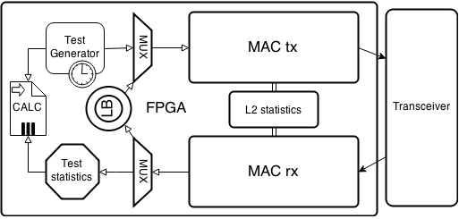
MAC ядро представлено двумя блоками: один на прием, другой на передачу. Это позволяет независимо принимать и отправлять пакеты, т.е. нет взаимовлияния очереди отправки на очередь приема и наоборот. Также с двух независимых блоков возможно вести общую статистику по полученному и отправленному трафику независимо от типа теста. Данные с блока передачи поступают на трансмиттер и отправляются в сеть, а входящие данные с трансивера поступают в блок приема.
Поскольку для некоторых топологий тестов необходим функционал шлейфа (loopback, петля), то он реализован отдельным блоком. Возможно установить шлейф уровня L1-L4:
- L1 — просто заворачивает трафик обратно (происходит это еще в трансивере)
- L2 — меняет DstMAC<->SrcMAC местами, пересчитывает FCS
- L3 — меняет DstMAC<->SrcMAC и DstIP<->SrcIP местами, пересчитывает FCS
- L4 — меняет DstMAC<->SrcMAC, DstIP<->SrcIP и DstPort<->SrcPort, пересчитывает FCS
Статистика по пакетам ведется и для режима шлейфа тоже, что позволяет грубо оценить соотношение отправленных и принятых пакетов.
Модуль генератора для каждого типа теста свой, для BERT он содержит генератор ПСП всех заявленных типов.
Работает это следующим образом. От генератора ПСП поступают данные на мультиплексор (проще говоря коммутатор), который, если не включен какой-то другой канал в данный момент, направляет поток в MAC tx модуль. MAC tx модуль, в соответствии с настройками теста (уровень BERT, размер пакета, данные полей) формирует из ПСП валидный Ethernet-фрейм и отправляет его в трансивер, который в свою очередь отправляет его в сеть. В зависимости от топологии теста фрейм либо заворачивается удаленной стороной, либо анализируется. В любом случае первичная обработка пакета не отличается. Фрейм попадает на MAC rx ядро, которое отправляет его на мультиплексор. Мультиплексор в зависимости от режима работы прибора направляет пакет либо в Loopback модуль, откуда после обработки он сразу же направляется в MAC tx для отправки, либо в модуль обработки и статистики теста, где, если потребуется, будет проведена попытка синхронизации ПСП и выполнено сравнение исходной последовательности с полученной. Результаты обработки отдаются в модуль вывода статистики.
Использование FPGA или ASIC позволяет все операции проводить параллельно, что не вносит какие либо задержки на обработку и исключает взаимовлияние модулей обработки.
Заключение
Несмотря на всю кажущуюся простоту алгоритмов и методик, за ними стоит много лет серьезных исследований. Огромное число факторов до сих пор влияет как на точность измерений, так и на стоимость приборов (прецизионные элементы, высокоскоростные ПЛИС). Например, приведенный выше BER тест не отличается значительной сложностью в общем алгоритмическом плане, но требует знаний в области математики, информатики и теории информации для разработки жизнеспособной модели. Модификация BER теста для пакетных сетей (поддержка уровней L2-L4) требует глубокого понимания принципов коммутации и маршрутизации. Надеюсь, что подобного рода статьи интересны и приносят пользу. В следующих публикациях планирую написать про сертифицированные тесты, генераторы трафика, фильтры и аналитические комплексы. Ведь как сказал Джон Фицджеральд Кеннеди на выступлении перед гражданами США перед стартом Лунной программы:
“И мы сделаем это. Не потому, что это легко, а потому что трудно.”
PS. Задавайте вопросы и предлагайте темы, в рамках нашей компетенции готовы на все 
 This article will be rather short in comparison with the others in the mini-series about various Ethernet/IP testing methods but it is one that is necessary as Bit Error Tests have a long tradition in telco environment (circuit based networks) but are still quite valid even in nowadays packet networks – at least for some specific cases. So without further delay let start with some theory behind the testing and some practical use followed by some use cases and best practices.
BERT introduction
As you can guess from the name this test is really to test physical layer traffic for any anomalies. This is a result from the test origins where T1/E1 circuits have been tested and each bit in each time-slot mattered as the providers were using those up to the limit as bandwidth was scarce. Also as most of the data being transferred were voice calls any pattern alterations had quite serious implications on the quality of service. This also led to the (in)famous reliability of five nines or the 99.999% which basically states that the link/device must be available 99.999% throughout a specified SLA period (normally a month or a year). One must remember that redundancy was rather rare so the requirements for hardware reliability was really high. But by the move away from the circuit-based TDM networks towards the packet-based IP networks the requirements changed. The bandwidth is now in abundance in most places and the wide deployment of advanced Ethernet and IP feature rich devices provides with plenty options for redundancy and QoS with packet-switched voice traffic on rise – one would think it is not really necessary to consider BERT as something one should use as test method but that would be huge mistake.
Why BERT
There are few considerations that can make BERT an interesting choice. I will list some I think are the most interesting.
- It has been designed to run for extended period of time which makes it ideal for acceptance testing which is still often required
- BERT is ideal for testing jitter as it was one of the primary design goals
- The different patters used in BERT can be used for packet optimization testing (I will discuss this later in more detail)
- Most of the BERT tests are smarter than just counting bit errors so the test can be used for other testing
BERT Physical setup and considerations
On Ethernet network you cannot run a simple L1 test unless you test just a piece of cable or potentially a hub as all other devices would require some address processing. This makes the test being different on Ethernet network from unframed E1 as unlike on E1 we need to set framing to Ethernet with the source and destination defined on the tester. Also as Ethernet must be looped on a logical level it is not possible to use simple RJ45 with pair of wires going from TX to RX as you could with E1 and either hardware or software loopback reflector is required. Most tester will actually allow you to specify even layer 3 and 4 for IP addresses and UDP ports. The reason is usually so the management traffic between tester and loopbacks can use this channel for internal communication.
Pattern selection options
As this test originates from the telco industry some interesting options are usually presented on the testers. The stream can generate these patterns:
- All zeros or all ones – which are specific patters originated from TDM environment
- 0101 pattern and 1010 pattern – patterns that can be easily compressed
- PRBS – Pseudo Random Bit Sequence – is an deterministic sequence that cannot be compressed/optimized the details and calculation can be found on wikipedia
- Inverted PRBS – the same as above but the calculation function is inversed to counter any “optimization” for the PRBS
The thing to remember is that PRBS will be applied to the payload of the frame/packet/datagram so it there is any sort of optimization present it will have no effect as PRBS is by design not compressible. There are various “strengths” of the pseudo-random pattern the higher the number the less repeating it will include. Normally it is possible to see two main variants: 2^15 which is 32,767 bits long and 2^23 which 8,388,607 bits long. Obviously the longer the pattern the better and more “random” behavior it emulates.
Error injecting Options
As this test originated in telco world injecting errors was a major thing but in Ethernet network it lost its importance. If you inject even a single bit error in an Ethernet frame the CRC should be incorrect and the whole frame should be dropped on first L2 equipment it will be passed through which should always result in alarm LoF(Loss of Frame)/LoP (Loss of Pattern).
Use cases, Best Practices and Conclusion
The most common use case for BERT in nowadays network would be in commissioning new links as you can run a fairly simple test for a long time that will give you a reasonable idea bout it’s quality in terms of frames drops and jitter.
The few recommendations about how to run this test would be as follows:
- Use the largest pattern you can.
- Remember that the line rate and L2 rates will be different because of the overheads.
- Remember that 99.999% of availability results in 0.8s outage in 24 hours (which can be quite a lot of frames)
- PRBS cannot be optimized
So as you can see BERT is rather simple and straight forward test that even though is in many ways deprecated by RFC2544 and others (like Y.156sam) it is still a very good test to know especially if you are in jitter sensitive environment e.g. where VoIP and IPTV is deployed.
Bit Error Rate Testing
This feature module describes how to configure a Bit Error Rate Test (BERT) and display the test results for channelized line
cards in the Cisco ASR 901 Series Aggregation Services Routers.
Finding Feature Information
Your software release may not support all the features documented in this module. For the latest feature information and caveats,
see the release notes for your platform and software release. To find information about the features documented in this module,
and to see a list of the releases in which each feature is supported, see the Feature Information for Bit Error Rate Testing.
Use Cisco Feature Navigator to find information about platform support and Cisco software image support. To access Cisco Feature
Navigator, go to
http://www.cisco.com/go/cfn
.
An account on Cisco.com is not required.
Prerequisites for
BERT
-
To run BERT in unframed mode on
a controller, you should set the “framing” configuration of the controller to
“unframed”. -
When running BERT, your system expects to receive the same pattern
that it is transmitting. If traffic is not being transmitted or received,
create a back-to-back loopback BERT on the link or in the network, and send out
a predictable stream to ensure that you receive the same data that was
transmitted. -
To determine if the remote serial port returns the BERT pattern
unchanged, you must manually enable network loopback at the remote serial port
while you configure a BERT pattern to use in the test at specified time
intervals on the local serial port.
Restrictions
-
BERT affects the functionality of any configured protocol on a controller on which it is initiated. The configured protocol
functionality is resumed after the BERT process is completed or successfully canceled. -
BERT is not supported for channelized E1/T1 (per time slot).
Feature Overview
The BERT feature is used to test the integrity of the physical layer. Using this feature, you can test cables and diagnose
signal problems in the field.
BERT generates a specific pattern on to the egress data stream of a E1/T1 controller and then analyzes the ingress data stream
for the same pattern. The bits that do not match the expected pattern are counted as bit errors.
The bit error rate (BER) is determined by comparing the erroneous bits received with the total number of bits received. You
can display and analyze the total number of error bits transmitted and the total number of bits received on the link. You
can retrieve error statistics anytime during the BERT.
The ASR 901 router uses Pseudo-Random Binary Sequences (PRBSs) for the BERT. The following table lists the PRBSs supported
on the ASR 901 routers.
|
BERT Pattern |
Description |
|---|---|
|
0’s |
Test pattern consisting of all 0’s that is used to test line coding |
|
1’s |
Test pattern consisting of all 1’s that is used to test alternating line volt and repeaters |
|
2^11 |
Pseudo-random repeating test pattern that consists of 2,048 bits |
|
2^15 |
Pseudo-random repeating test pattern that consists of 32,767 bits |
|
2^20 QRSS |
Pseudo-random repeating test pattern that consists of 1,048,575 bits |
|
Alt 0’s and 1’s |
Test pattern consisting of alternating 0’s and 1’s that is used to test the preamp and equalizer |
How to Configure BERT
The ASR 901 router supports BERT on all 16 E1/T1 controllers simultaneously. Additionally, you can cancel an already initiated
BERT.
This section describes how to configure and perform a BERT on E1/T1 controllers, and how to stop or verify the test:
Performing BERT on a
T1/E1 Line
To enable BERT
pattern on a T1 or E1 controller, perform the following steps.
Procedure
| Command or Action | Purpose | |
|---|---|---|
| Step 1 |
enable Example: |
Enables the
|
| Step 2 |
configure Example: |
Enters the |
| Step 3 |
controller Example: |
Selects a T1 or |
| Step 4 |
bert Example: |
Sends a BERT
|
Terminating BERT on
a T1/E1 Controller
Procedure
| Command or Action | Purpose | |
|---|---|---|
| Step 1 |
enable Example: |
Enables the
|
| Step 2 |
configure Example: |
Enters the |
| Step 3 |
controller Example: |
Selects a T1 or |
| Step 4 |
no Example: |
Terminates the |
Verifying BERT on a T1/E1 Controller
To verify that BERT is running on a T1/E1 controller, enter the show controllers command at any time during the test.
Router# show controllers e1 0/9
E1 0/9 is up.
Applique type is Channelized E1 - balanced
DSX1 BERT pattern : 2^15
DSX1 BERT sync : sync
DSX1 BERT sync count : 1
DSX1 BERT interval : 1
DSX1 BERT time remain : 49
DSX1 BERT total errs : 0
DSX1 BERT total k bits: 21068
DSX1 BERT errors (last): 0
DSX1 BERT k bits (last): 21068
Last clearing of BERT counters never
No alarms detected.
alarm-trigger is not set
Framing is crc4, Line Code is HDB3, Clock Source is Internal.
Data in current interval (68 seconds elapsed):
1 Line Code Violations, 0 Path Code Violations
0 Slip Secs, 0 Fr Loss Secs, 1 Line Err Secs, 1 Degraded Mins
0 Errored Secs, 0 Bursty Err Secs, 0 Severely Err Secs, 0 Unavail Secs
Configuration Examples
The following is a sample configuration of the BERT feature.
Router#configure terminal
Enter configuration commands, one per line.  End with CNTL/Z.
Router(config)#controller e1 0/9
Router(config-controller)#bert pattern 2^15 interval 1
Additional References
The following sections provide references related to bit error rate testing.
Related Documents
|
Related Topic |
Document Title |
|---|---|
|
Cisco IOS Commands |
Cisco IOS Master Commands List, All Releases |
|
ASR 901 Command Reference |
Cisco ASR 901 Series Aggregation Services Router Command Reference |
|
Cisco IOS Interface and Hardware Component Commands |
Cisco IOS Interface and Hardware Component Command Reference |
Standards
|
Standard |
Title |
|---|---|
|
None |
— |
MIBs
|
MIB |
MIBs Link |
|---|---|
|
None |
To locate and download MIBs for selected platforms, Cisco IOS releases, and feature sets, use Cisco MIB Locator found at the http://www.cisco.com/go/mibs |
RFCs
|
RFC |
Title |
|---|---|
|
None |
— |
Technical Assistance
|
Description |
Link |
|---|---|
|
The Cisco Technical Support website contains thousands of pages of searchable technical content, including links to products, |
http://www.cisco.com/techsupport |
Feature Information
for Bit Error Rate Testing
The following table
lists the features in this module and provides links to specific configuration
information.
Use Cisco Feature
Navigator to find information about platform support and software image
support. Cisco Feature Navigator enables you to determine which software images
support a specific software release, feature set, or platform. To access Cisco
Feature Navigator, go to
http://www.cisco.com/go/cfn . An account on Cisco.com is
not required.
 Note |
The following |
|
Feature |
Releases |
Feature |
|---|---|---|
|
Bit Error |
15.2(2)SNG |
This |