
-
#2
It was already found before, no solution was found.
ESP32 first try: works with Arduino, but not in B4R
HI, All Strange, my ESP8266 project works OK in B4R, but now i’m trying to start with ESP32 … with no success. Arduino IDE connects, starts the board OK, logging is OK, the reset button makes the reset OK. In B4R the flashing of the min template app is OK, but no log output. Sub…

www.b4x.com

-
#3
I also ordered the same board — waiting for it to arrive
check this:

-
#4
I also ordered the same board — waiting for it to arrive
check this:
Thank you all for the reply.
@f0raster0 I tried this in the CameraWebServer example and the result follows and it’s the same:
  // I have changed the code into the following according
  //to what is suggested in the page you provided

  // camera init
  esp_err_t err;
  err = esp_camera_init(&config);
  if (err != ESP_OK) {
    Serial.printf("Camera init failed with error 0x%x", err);
    return;
  }
The result is this (logged in Arduino) :
10:26:22.984 ->
10:26:22.984 -> rst:0x1 (POWERON_ESET),boot:0x13 (SPI_FAST_FLASH_BOOT)
10:26:22.984 -> configsip: 0, SPIWP:0xee
10:26:22.984 -> clk_drv:0x00,q_drv:0x00,d_drv:0x00,cs0_drv:0x00,hd_rv:0x00,p_drv:0x00
10:26:22.984 -> modeIO, clock div:1
10:26:22.984 -> load:0x3fff0030,len:1420
10:26:22.984 -> ho 0 tail 12 room 4
10:26:22.984 -> load:0x40078000,len:13540
10:26:22.984 -> load:0x40080400,len:3604
10:26:22.984 -> entry 0x400805f0
10:26:24.137 ->
10:26:24.182 -> E (929) camera: Camera probe failed with error 0x105(ESP_ERR_NOT_FOUND)
10:26:24.182 -> Camera init failed with error 0x105
-
#5
have you seen this:
Esp32 Cam with error in monitor
Hi, for anybody still struggling with a similar issue, I have the same hardware as the pics from tiny-james and I did make it work with the sample example (Webserver) just carefully selecting the correct camera module. In my case, the one in the uploaded picture. Hope this helps.

forum.arduino.cc
post #20 #21 #22
-
#6
have you seen this:

Esp32 Cam with error in monitor
Hi, for anybody still struggling with a similar issue, I have the same hardware as the pics from tiny-james and I did make it work with the sample example (Webserver) just carefully selecting the correct camera module. In my case, the one in the uploaded picture. Hope this helps.
forum.arduino.ccpost #20 #21 #22
Thanks @f0raster0 for your help and efforts. I have seen the video by «Dronebot Workshop» in youtube about ESP32CAM and I knew about this. I have tried all models and after not finding a solution i ended up asking for help here.
-
#7
I got my ESP32-CAM then we can run a couple test together if needed..
this is my «hello world» (esp32-cam from alliexpress)


Last edited: Jan 21, 2022
-
#8
1) Do you get logs in B4R?
2) Do you hard reset from the motherboard or from the board?
3) When it works it is on the motherboard right?
-
#9
1) Do you get logs in B4R?
2) Do you hard reset from the motherboard or from the board?
3) When it works it is on the motherboard right?
3) yes, like in the picture, together.
2) after programing just push the reset button
1) I don’t have any exmple to test using B4R, send me one and will do.. my understand is you can’t make it working in B4R or Arduino — i did the power up/test using Arduino.
Last edited: Jan 21, 2022
-
#10
For number 1 try this example:
ESP32 Camera Picture Capture and Video Streaming! (Updated with code!)
Hello! Last December I made a request for support for the ESP32 Camera support. Well, I finally found the time to work on it myself and here’s my initial attempt at implementing this with B4R. I’m using an ESP32CAM camera board with 4GB of PSRAM (like extended memory for the camera). I’m…
www.b4x.com
For number 2 can you please clarify which reset button? There are 2 reset buttons, one on the board and one on the motherboard.
-
#11
For number 1 try this example:
ESP32 Camera Picture Capture and Video Streaming! (Updated with code!)
Hello! Last December I made a request for support for the ESP32 Camera support. Well, I finally found the time to work on it myself and here’s my initial attempt at implementing this with B4R. I’m using an ESP32CAM camera board with 4GB of PSRAM (like extended memory for the camera). I’m…
www.b4x.comFor number 2 can you please clarify which reset button? There are 2 reset buttons, one on the board and one on the motherboard.
Why don’t you make it working with Arduino first?
To test your hardware using Arduino.. then use your B4R
Edit: RST — I saw just one button, I did the test in <10min then don’t remember.. will check tomorrow
Edit2: ahhhh that b4r example looks a lot more thst 10min 

 try Arduino first!!!
Last edited: Jan 22, 2022
-
#13
I installed B4R… (this is the second time trying to use this IDE)
1) I did a simple test:
#Region Project Attributes
    #AutoFlushLogs: True
    #CheckArrayBounds: True
    #StackBufferSize: 600
#End Region
'Ctrl+Click to open the C code folder: ide://run?File=%WINDIR%System32explorer.exe&Args=%PROJECT%ObjectsSrc

Sub Process_Globals
    Public Serial1 As Serial
    Private wifi As ESP8266WiFi
End Sub

Private Sub AppStart
    Serial1.Initialize(115200)
    Log("AppStart")
    'example of connecting to a local network
    If wifi.Connect2("HUAWEI", "doITsuper#SIMPLE123") Then
        Log("Connected to network")
    Else
        Log("Failed to connect to network")
    End If
End Sub
1.1) Reset the board
2) the board connects to my wifi without problems
3) Logs doesn’t work properly.. a way to see them:
Start Arduino IDE, Open Serial Monitor — connect to the port — then click «connect» in b4R IDE

EDIT: Now my board doesn’t work in Arduino
Camera init failed with error 0x20004 — Solved:
Last edited: Jan 22, 2022
-
#14
I have tried it in Arduino the first time I held it in my hands. In Arduino logs are ok but in B4R not. I told you to to use the B4R code to tell us if you see any logs.
-
#15
View attachment 124559
EDIT: Now my board doesn’t work in Arduino
Camera init failed with error 0x20004 — Solved:
Can you please share what was wrong and how did you manage to solve it?
-
#16
I have tried it in Arduino the first time I held it in my hands. In Arduino logs are ok but in B4R not. I told you to to use the B4R code to tell us if you see any logs.
if it work using Arduino then problem solved!!
then we b4r need to be checked, we have the same issue like @peacemaker wrote here
ESP32 first try: works with Arduino, but not in B4R
HI, All Strange, my ESP8266 project works OK in B4R, but now i’m trying to start with ESP32 … with no success. Arduino IDE connects, starts the board OK, logging is OK, the reset button makes the reset OK. In B4R the flashing of the min template app is OK, but no log output. Sub…
www.b4x.com
Can you please share what was wrong and how did you manage to solve it?
yes, removed B4R
EDIT: I just watched your video same situation here.. if you start Arduino you can see the logs. Anyway, I’m not going to install b4r again, sorry (until finish a project that I have to do)
Last edited: Jan 23, 2022
-
#17
I have bought from AliExpress some OV2640 Cameras. I connected one of them to the ESP32CAM and finally I got it working perfectly running the CameraWebServer example from the Arduino ESP32 Examples.

After releasing some projects with the ESP32-CAM, some readers reported issues when trying to use the ESP32-CAM. This guide is a compilation with the most common errors when using the ESP32-CAM and how to fix them.

We’ve released the following projects with the ESP32-CAM:
- Video Streaming, Face Detection and Face Recognition
- ESP32 IP CAM – Video Streaming (Home Assistant and Node-RED)
- Take Photo and Save to MicroSD Card
- PIR Motion Detector with Photo Capture
- Take Photo, Save to SPIFFS and Display in Web Server
Note: some of our readers reported errors when trying to follow the ESP32-CAM project with Home Assistant. We’ve modified some lines on the code, so most of the problems related with that project should be fixed.
Please note that we couldn’t reproduce some of the errors on our end. However, we’ve gathered all the information given by our readers to get answers to the most common issues.
If you have a different problem or a different solution to these issues, you can share your tips by writing a comment below.
Most common errors:
- Failed to connect to ESP32: Timed out waiting for packet header
- Camera init failed with error 0x20001 or similar
- Brownout detector or Guru meditation error
- Sketch too big error – Wrong partition scheme selected
- Board at COMX is not available – COM Port Not Selected
- Psram error: GPIO isr service is not installed
- Weak Wi-Fi Signal
- No IP Address in Arduino IDE Serial Monitor
- Can’t open web server
- The image lags/shows lots of latency
- esp_camera_fb_get(): Failed to get the frame on time!
1. Failed to connect to ESP32: Timed out waiting for packet header

This error means that the ESP32-CAM is not in flashing mode or it is not connected properly to the FTDI programmer.
Double-check the steps to upload code
Double-check that you’ve followed the exact steps to put your ESP32-CAM in flashing mode. Failing to complete one of the steps may result in that error. Here’s the steps you need to follow:
Connect the ESP32-CAM board to your computer using an FTDI programmer. Follow the next schematic diagram:

Important: GPIO 0 needs to be connected to GND so that you’re able to upload code.
Many FTDI programmers have a jumper that allows you to select 3.3V or 5V. Make sure the jumper is in the right place to select 5V.
Important: GPIO 0 needs to be connected to GND so that you’re able to upload code.
| ESP32-CAM | FTDI Programmer |
| GND | GND |
| 5V | VCC (5V) |
| U0R | TX |
| U0T | RX |
| GPIO 0 | GND |
To upload the code, follow the next steps:
1) Go to Tools > Board and select AI-Thinker ESP32-CAM.
2) Go to Tools > Port and select the COM port the ESP32 is connected to.
3) Then, click the upload button to upload the code.
4) When you start to see these dots on the debugging window as shown below, press the ESP32-CAM on-board RST button.

After a few seconds, the code should be successfully uploaded to your board.
GPIO 0 must be connected to GND
Important: if you can’t upload the code, double-check that GPIO 0 is connected to GND and that you selected the right settings in the Tools menu. You should also press the on-board Reset button to restart your ESP32 in flashing mode. Also, check that you have the FTDI programmer jumper cap set to 5V.
Check the FTDI programmer you are using
One of our readers reported the following: “found out that you can program the board with a USB-to-TTL module model CP2102 and that the CH340 model does NOT work“. This is the FTDI programmer we’re using.
Power the ESP32-CAM with 5V
Some of our readers reported that they could only upload code when the ESP32 was powered with 5V. So, power the ESP32-CAM with 5V.
FTDI Programmer 5V
Measure the output voltage of your FTDI programmer (VCC and GND) using a Multimeter to ensure it’s providing 5V to your ESP32-CAM.

2. Camera init failed with error 0x20001 or similar

If you get this exact error, it means that your camera OVX is not connected properly to your ESP32 board or you have the wrong pin assignment in the code.
Sometimes, unplugging and plugging the FTDI programmer multiple times or restart the board multiple times, might solve the issue.
Camera not connected properly
The camera has a tiny connector and you must ensure it’s connected in the the right away and with a secure fit, otherwise it will fail to establish a connection.
Wrong pin assignment in the code
When you get this error, it might also mean that you didn’t select the right board in the define section or the pin definition is wrong for your board.
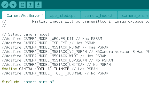
Make sure you select the right camera module in your projects. You just need to uncomment the right camera module and comment all the others:
//#define CAMERA_MODEL_WROVER_KIT
//#define CAMERA_MODEL_M5STACK_PSRAM
#define CAMERA_MODEL_AI_THINKER
In this example, we’re using the CAMERA_MODEL_AI_THINKER, so it’s the one that is enabled. Otherwise, it will fail the pin assignment and the camera will fail to init.
There are many esp32-cam boards being released (“fake boards”) that the wiring between the ESP32 and the OV camera might be different, so selecting the camera module, might not be enough. You might need to check each gpio declaration with your board pinout.
For example, M5Stack board without PSRAM has a different pin assignment than the M5STACK with PSRAM (defined on the code by default). So, you need to change the pin definition in the code accordingly to the board pinout.
Not enough power through USB source
If you’re powering your ESP32 through a USB port on your computer, it might not be supplying enough power.
Faulty FTDI programmer
Some readers also reported this problem was solved by replacing their actual FTDI programmer with this one.
The camera/connector is broken
If you get this error, it might also mean that your camera or the camera ribbon is broken. If that is the case, you may get a new OV2640 camera probe.
3. Brownout detector or Guru meditation error
When you open your Arduino IDE Serial monitor and the error message “Brownout detector was triggered” is constantly being printed over and over again. It means that there’s some sort of hardware problem.
It’s often related to one of the following issues:
- Poor quality USB cable;
- USB cable is too long;
- Board with some defect (bad solder joints);
- Bad computer USB port;
- Or not enough power provided by the computer USB port.
Solution:
- try a different shorter USB cable (with data wires)
- use a different computer USB port or use a USB hub with an external power supply
- some readers reported that when powering the ESP32-CAM with 5V, the issue was fixed.
Also, follow the suggestions described in issue 2.
4. Sketch too big error – Wrong partition scheme selected

When you get the following error:
Sketch too big; see http://www.arduino.cc/en/Guide/Troubleshooting#size for tips on reducing it.
Error compiling for board ESP32 Dev Module.
It means that you haven’t selected the right partition scheme. Make sure you select the right partition scheme. In your Arduino IDE, go to Tools > Partition Scheme, select “Huge APP (3MB No OTA)“.
5. Board at COMX is not available – COM Port Not Selected

If you get the following error or similar:
serial.serialutil.SerialException: could not open port 'COM8': WindowsError(2, 'The system cannot find the file specified.')
Failed to execute script esptool
the selected serial port Failed to execute script esptool
 does not exist or your board is not connected
Board at COM8 is not available
It means that you haven’t selected the COM port in the Tools menu. In your Arduino IDE, go to Tools > Port and select the COM port the ESP32 is connected to.
It might also mean that the ESP32-CAM is not establishing a serial connection with your computer or it is not properly connected to the USB connector.
6. Psram error: GPIO isr service is not installed

You are using a board without PSRAM and you get the following error or similar:
E (161) gpio: gpio_isr_handler_remove(380): GPIO isr service is not installed, call gpio_install_isr_service() first
Camera init failed with error 0x101
when the board was initialized with the following settings:
config.frame_size = FRAMESIZE_UXGA;
config.jpeg_quality = 10;
config.fb_count = 2;
Adding the following fixes the issues (it lowers the image resolution so it won’t need so much space to store images. However, as a result, you cannot get some high resolution formats due to the limited memory):
if(psramFound()){
  config.frame_size = FRAMESIZE_UXGA;
  config.jpeg_quality = 10;
  config.fb_count = 2;
} else {
  config.frame_size = FRAMESIZE_SVGA;
  config.jpeg_quality = 12;
  config.fb_count = 1;
}
Note: face recognition and detection doesn’t work with boards without PSRAM. However, you can still use all the other functionalities of the board. For example, although you can’t use the face recognition and detection features of this project (ESP32-CAM Video Streaming and Face Recognition with Arduino IDE), you can still play with the example and explore the board features as long as you have the right pin assignment in the code.
7. Weak Wi-Fi Signal
Some readers reported that after powering the ESP32-CAM with 5V, they’ve gotten a more stable Wi-Fi signal. You can read this dedicated guide to learn how to connect an external antenna to the ESP32-CAM and extend Wi-Fi coverage.
The ESP32-CAM has the option to use either the built-in antenna or an external antenna. If your ESP32-CAM AI-Thinker has no Wi-Fi connection or poor connection, it might have the external antenna enabled. If you connect an external antenna to the connector, it should work fine.
Check if the jumper 0K resistor by the antenna connector is in the proper position for the desired antenna. There are 3 little white squares laid out like a “<” with the middle position being common.

The following photo shows a closer look at that area. You can clearly see a small 0K resistor connecting to the built-in antenna.

With board turned so the the PCB antenna is up:
- To use the PCB antenna, the resistor must be on the top position, like this: /
- For the antenna connector, the resistor must be on the bottom position, like this:
So, to enable the on-board antenna:
- Unsolder the resistor that goes to the antenna, it’s in this position
- And solder together the two connections to enable the on-board antenna.
8. No IP Address in Arduino IDE Serial Monitor
f you just see dots printed in the serial monitor (……), it means that your ESP32-CAM is not establishing a Wi-Fi connection with your router.
Double-check your network credentials
You need to make sure that you’ve typed your exact network credentials (SSID and password) in the following variables:
const char* ssid = "REPLACE_WITH_YOUR_SSID";
const char* password = "REPLACE_WITH_YOUR_PASSWORD";
Select the right baud rate in the Arduino IDE Serial Monitor
If you don’t select the right baud rate in the Arduino IDE Serial Monitor, you won’t get your board IP address or you’ll just get garbage on the screen.
Make sure you select the right baud rate. In our examples with the ESP32-CAM, we use 115200 baud rate.
Reset the board multiple times
You might also need to press the ESP32-CAM on-board RESET button multiple times to restart your ESP and print the IP address during boot.
RX and TX swapped
Double-check the connections between your ESP32 board and the FTDI programmer. RX goes to TX and TX goes to RX. If these connections are swapped, the ESP32-CAM is not able to establish a serial communication with your computer.
Wi-Fi Range
If the router is far away from your ESP32 board, it might not be able to catch the Wi-Fi signal. Ensure that your ESP32-CAM is fairly close to your router.
9. Can’t open web server
If the ESP32-CAM is printing the IP address in your Arduino IDE Serial Monitor, but when you try to open the web server in your web browser you see a blank screen, it usually means that you are trying to access the ESP32-CAM web server with multiple web browser tabs.
At the moment, these ESP32-CAM sketches only work with one client connected at a time.
10. The image lags/shows lots of latency
Having some latency is normal for such a small and cheap camera. Some readers have suggested the following to reduce latency:
- Power the ESP32-CAM with a standalone 5V power supply
- Reduce the frame size with the following in your code:
config.frame_size = FRAMESIZE_SVGA or config.frame_size = FRAMESIZE_VGA - Use an external antenna.
11. esp_camera_fb_get(): Failed to get the frame on time!
We’ve personally never faced this issue. However, many readers are getting this error with their ESP32-CAM boards.
One of our readers (Fibula) suggested the following to solve this issue:
“Im using the ESP32-CAM Module 2MP OV2640 Camera sensor Module Type-C USB module from Aliexpress. Although not mentioned, It doesn’t have the extra PSRAM the other M5 models do, and the camera has one changed IO pin.
See here: https://github.com/m5stack/m5stack-cam-psram/blob/master/README.md and scroll down to Interface Comparison.
The CameraWebServer Arduino example we’re probably all using doesn’t have this ESP32-CAM model defined.
You need to add it yourself in the main tab add:
#define CAMERA_MODEL_M5STACK_NO_PSRAMAnd in the camera_pins.h tab add the following:
#elif defined(CAMERA_MODEL_M5STACK_NO_PSRAM)
#define PWDN_GPIO_NUM -1
#define RESET_GPIO_NUM 15
#define XCLK_GPIO_NUM 27
#define SIOD_GPIO_NUM 25
#define SIOC_GPIO_NUM 23
#define Y9_GPIO_NUM 19
#define Y8_GPIO_NUM 36
#define Y7_GPIO_NUM 18
#define Y6_GPIO_NUM 39
#define Y5_GPIO_NUM 5
#define Y4_GPIO_NUM 34
#define Y3_GPIO_NUM 35
#define Y2_GPIO_NUM 17
#define VSYNC_GPIO_NUM 22
#define HREF_GPIO_NUM 26
#define PCLK_GPIO_NUM 21
And you’re good to go.
Also note that the max resolution of the bare ESP32-CAM Module is XGA 1024×768, I assume also because of the lack of PSRAM. “
We hope this suggestion solves your issue. Let us know in the comments section.
Using larger microSD card sizes
According to he datasheet, the ESP32-CAM should only supports 4GB microSD cards.
However, we’ve tested with 16GB microSD card and it works well.
You might not be able to store more than 4GB, even though you have 16GB. We haven’t tested storing more than 4GB, so we’re not sure about this.
Are these projects compatible with M5Stack board?
Yes, the M5Stack ESP32 board is compatible with out projects. However, you must check your camera pinout to ensure you have the right assignment in the code.
You can check the M5Stack camera connections here.
How to set a fixed the IP Address
To set a static/fixed IP address, you can follow the next tutorial:
- ESP32 Static/Fixed IP Address
Setting ESP32-CAM as Access Point (AP)
You can set your ESP32-CAM as an Access Point (AP). This means you are able to connect to your ESP32-CAM directly without having to connect to your router. You can use the following code to set your video streaming web server as an Access Point:
/*********
  Rui Santos
  Complete project details at https://RandomNerdTutorials.com/esp32-cam-video-streaming-web-server-camera-home-assistant/

  IMPORTANT!!!
   - Select Board "AI Thinker ESP32-CAM"
   - GPIO 0 must be connected to GND to upload a sketch
   - After connecting GPIO 0 to GND, press the ESP32-CAM on-board RESET button to put your board in flashing mode

  Permission is hereby granted, free of charge, to any person obtaining a copy
  of this software and associated documentation files.

  The above copyright notice and this permission notice shall be included in all
  copies or substantial portions of the Software.
*********/

#include "esp_camera.h"
#include <WiFi.h>
#include "esp_timer.h"
#include "img_converters.h"
#include "Arduino.h"
#include "fb_gfx.h"
#include "soc/soc.h" //disable brownout problems
#include "soc/rtc_cntl_reg.h"  //disable brownout problems
#include "esp_http_server.h"

// Replace with your network credentials
const char* ssid     = "ESP32-Access-Point";
const char* password = "123456789";

#define PART_BOUNDARY "123456789000000000000987654321"

// This project was tested with the AI Thinker Model, M5STACK PSRAM Model and M5STACK WITHOUT PSRAM
#define CAMERA_MODEL_AI_THINKER
//#define CAMERA_MODEL_M5STACK_PSRAM
//#define CAMERA_MODEL_M5STACK_WITHOUT_PSRAM

// Not tested with this model
//#define CAMERA_MODEL_WROVER_KIT

#if defined(CAMERA_MODEL_WROVER_KIT)
  #define PWDN_GPIO_NUM    -1
  #define RESET_GPIO_NUM   -1
  #define XCLK_GPIO_NUM    21
  #define SIOD_GPIO_NUM    26
  #define SIOC_GPIO_NUM    27

  #define Y9_GPIO_NUM      35
  #define Y8_GPIO_NUM      34
  #define Y7_GPIO_NUM      39
  #define Y6_GPIO_NUM      36
  #define Y5_GPIO_NUM      19
  #define Y4_GPIO_NUM      18
  #define Y3_GPIO_NUM       5
  #define Y2_GPIO_NUM       4
  #define VSYNC_GPIO_NUM   25
  #define HREF_GPIO_NUM    23
  #define PCLK_GPIO_NUM    22

#elif defined(CAMERA_MODEL_M5STACK_PSRAM)
  #define PWDN_GPIO_NUM     -1
  #define RESET_GPIO_NUM    15
  #define XCLK_GPIO_NUM     27
  #define SIOD_GPIO_NUM     25
  #define SIOC_GPIO_NUM     23

  #define Y9_GPIO_NUM       19
  #define Y8_GPIO_NUM       36
  #define Y7_GPIO_NUM       18
  #define Y6_GPIO_NUM       39
  #define Y5_GPIO_NUM        5
  #define Y4_GPIO_NUM       34
  #define Y3_GPIO_NUM       35
  #define Y2_GPIO_NUM       32
  #define VSYNC_GPIO_NUM    22
  #define HREF_GPIO_NUM     26
  #define PCLK_GPIO_NUM     21

#elif defined(CAMERA_MODEL_M5STACK_WITHOUT_PSRAM)
  #define PWDN_GPIO_NUM     -1
  #define RESET_GPIO_NUM    15
  #define XCLK_GPIO_NUM     27
  #define SIOD_GPIO_NUM     25
  #define SIOC_GPIO_NUM     23

  #define Y9_GPIO_NUM       19
  #define Y8_GPIO_NUM       36
  #define Y7_GPIO_NUM       18
  #define Y6_GPIO_NUM       39
  #define Y5_GPIO_NUM        5
  #define Y4_GPIO_NUM       34
  #define Y3_GPIO_NUM       35
  #define Y2_GPIO_NUM       17
  #define VSYNC_GPIO_NUM    22
  #define HREF_GPIO_NUM     26
  #define PCLK_GPIO_NUM     21

#elif defined(CAMERA_MODEL_AI_THINKER)
  #define PWDN_GPIO_NUM     32
  #define RESET_GPIO_NUM    -1
  #define XCLK_GPIO_NUM      0
  #define SIOD_GPIO_NUM     26
  #define SIOC_GPIO_NUM     27

  #define Y9_GPIO_NUM       35
  #define Y8_GPIO_NUM       34
  #define Y7_GPIO_NUM       39
  #define Y6_GPIO_NUM       36
  #define Y5_GPIO_NUM       21
  #define Y4_GPIO_NUM       19
  #define Y3_GPIO_NUM       18
  #define Y2_GPIO_NUM        5
  #define VSYNC_GPIO_NUM    25
  #define HREF_GPIO_NUM     23
  #define PCLK_GPIO_NUM     22
#else
  #error "Camera model not selected"
#endif

static const char* _STREAM_CONTENT_TYPE = "multipart/x-mixed-replace;boundary=" PART_BOUNDARY;
static const char* _STREAM_BOUNDARY = "rn--" PART_BOUNDARY "rn";
static const char* _STREAM_PART = "Content-Type: image/jpegrnContent-Length: %urnrn";

httpd_handle_t stream_httpd = NULL;

static esp_err_t stream_handler(httpd_req_t *req){
  camera_fb_t * fb = NULL;
  esp_err_t res = ESP_OK;
  size_t _jpg_buf_len = 0;
  uint8_t * _jpg_buf = NULL;
  char * part_buf[64];

  res = httpd_resp_set_type(req, _STREAM_CONTENT_TYPE);
  if(res != ESP_OK){
    return res;
  }

  while(true){
    fb = esp_camera_fb_get();
    if (!fb) {
      Serial.println("Camera capture failed");
      res = ESP_FAIL;
    } else {
      if(fb->width > 400){
        if(fb->format != PIXFORMAT_JPEG){
          bool jpeg_converted = frame2jpg(fb, 80, &_jpg_buf, &_jpg_buf_len);
          esp_camera_fb_return(fb);
          fb = NULL;
          if(!jpeg_converted){
            Serial.println("JPEG compression failed");
            res = ESP_FAIL;
          }
        } else {
          _jpg_buf_len = fb->len;
          _jpg_buf = fb->buf;
        }
      }
    }
    if(res == ESP_OK){
      size_t hlen = snprintf((char *)part_buf, 64, _STREAM_PART, _jpg_buf_len);
      res = httpd_resp_send_chunk(req, (const char *)part_buf, hlen);
    }
    if(res == ESP_OK){
      res = httpd_resp_send_chunk(req, (const char *)_jpg_buf, _jpg_buf_len);
    }
    if(res == ESP_OK){
      res = httpd_resp_send_chunk(req, _STREAM_BOUNDARY, strlen(_STREAM_BOUNDARY));
    }
    if(fb){
      esp_camera_fb_return(fb);
      fb = NULL;
      _jpg_buf = NULL;
    } else if(_jpg_buf){
      free(_jpg_buf);
      _jpg_buf = NULL;
    }
    if(res != ESP_OK){
      break;
    }
    //Serial.printf("MJPG: %uBn",(uint32_t)(_jpg_buf_len));
  }
  return res;
}

void startCameraServer(){
  httpd_config_t config = HTTPD_DEFAULT_CONFIG();
  config.server_port = 80;

  httpd_uri_t index_uri = {
    .uri       = "/",
    .method    = HTTP_GET,
    .handler   = stream_handler,
    .user_ctx  = NULL
  };

  //Serial.printf("Starting web server on port: '%d'n", config.server_port);
  if (httpd_start(&stream_httpd, &config) == ESP_OK) {
    httpd_register_uri_handler(stream_httpd, &index_uri);
  }
}

void setup() {
  WRITE_PERI_REG(RTC_CNTL_BROWN_OUT_REG, 0); //disable brownout detector

  Serial.begin(115200);
  Serial.setDebugOutput(false);

  camera_config_t config;
  config.ledc_channel = LEDC_CHANNEL_0;
  config.ledc_timer = LEDC_TIMER_0;
  config.pin_d0 = Y2_GPIO_NUM;
  config.pin_d1 = Y3_GPIO_NUM;
  config.pin_d2 = Y4_GPIO_NUM;
  config.pin_d3 = Y5_GPIO_NUM;
  config.pin_d4 = Y6_GPIO_NUM;
  config.pin_d5 = Y7_GPIO_NUM;
  config.pin_d6 = Y8_GPIO_NUM;
  config.pin_d7 = Y9_GPIO_NUM;
  config.pin_xclk = XCLK_GPIO_NUM;
  config.pin_pclk = PCLK_GPIO_NUM;
  config.pin_vsync = VSYNC_GPIO_NUM;
  config.pin_href = HREF_GPIO_NUM;
  config.pin_sscb_sda = SIOD_GPIO_NUM;
  config.pin_sscb_scl = SIOC_GPIO_NUM;
  config.pin_pwdn = PWDN_GPIO_NUM;
  config.pin_reset = RESET_GPIO_NUM;
  config.xclk_freq_hz = 20000000;
  config.pixel_format = PIXFORMAT_JPEG;

  if(psramFound()){
    config.frame_size = FRAMESIZE_UXGA;
    config.jpeg_quality = 10;
    config.fb_count = 2;
  } else {
    config.frame_size = FRAMESIZE_SVGA;
    config.jpeg_quality = 12;
    config.fb_count = 1;
  }

  // Camera init
  esp_err_t err = esp_camera_init(&config);
  if (err != ESP_OK) {
    Serial.printf("Camera init failed with error 0x%x", err);
    return;
  }
  // Connect to Wi-Fi network with SSID and password
  Serial.print("Setting AP (Access Point)…");
  // Remove the password parameter, if you want the AP (Access Point) to be open
  WiFi.softAP(ssid, password);

  IPAddress IP = WiFi.softAPIP();
  Serial.print("Camera Stream Ready! Connect to the ESP32 AP and go to: http://");
  Serial.println(IP);

  // Start streaming web server
  startCameraServer();
}

void loop() {
  delay(1);
}
View raw code
To better understand how it works, you can read the next tutorial:
- ESP32 Access Point (AP) for Web Server
Wrapping Up
We hope you’ve found this troubleshooting guide useful and you were able to make your ESP32-CAM work with our projects.
If you have any other issues or suggestions on how to fix them, please post a comment below.
If you like this project, you may also like other projects with the ESP32-CAM:
- ESP32-CAM AI-Thinker Pinout Guide: GPIOs Usage Explained
- Video Streaming, Face Detection and Face Recognition
- Build ESP32-CAM Projects (eBook)
- Read all our ESP32-CAM Projects, Tutorials and Guides
Thank you for reading.
P.S. It is very difficult to understand what’s wrong with your project when we can’t reproduce the error on our end. However, if you post the error, there might be other readers with the same issue/solution, so we encourage you to interact in the comment’s section.
Содержание
- i have uploaded program on ESP32-CAM but at the end it is showing me 👇 #375
- Comments
- Camera init failed with error 0x105
- Re: ESP32 CAM: gpio_install_isr_service failed (105)
- Re: ESP32 CAM: gpio_install_isr_service failed (105)
- Re: ESP32 CAM: gpio_install_isr_service failed (105)
- B4R Question [SOLVED] Problems with ESP32-CAM-MB
- hatzisn
- 4.18US $ 12% OFF|Esp32-cam-mb Wifi Esp32 Cam Bluetooth Development Board With Ov2640 Camera Micro Usb To Serial Port Ch340g 4.75v-5.25v Nodemcu — Integrated Circuits — AliExpress
- Camera probe failed with error 0x105 about esp32-camera HOT 6 OPEN
- Comments (6)
- Related Issues (20)
- Recommend Projects
- React
- Vue.js
- Typescript
- TensorFlow
- Django
- Laravel
- Recommend Topics
- javascript
- server
- Machine learning
- Visualization
- Recommend Org
- Microsoft
- Camera init failed with error 0x105
- Re: gpio_install_isr_service() returns ESP_ERR_NOT_FOUND
- Re: gpio_install_isr_service() returns ESP_ERR_NOT_FOUND
- Re: gpio_install_isr_service() returns ESP_ERR_NOT_FOUND
- Re: gpio_install_isr_service() returns ESP_ERR_NOT_FOUND
- Re: gpio_install_isr_service() returns ESP_ERR_NOT_FOUND
i have uploaded program on ESP32-CAM but at the end it is showing me 👇 #375
E (894) camera: Camera probe failed with error 0x105(ESP_ERR_NOT_FOUND)
Camera init failed with error 0x105
The text was updated successfully, but these errors were encountered:
Setting PWDN_GPIO_NUM to LOW and then HIGH before calling esp_camera_init() helped me solve this error. Wrote the following wrapper with basic serial prints for it, see if it helps:
void initCam() <
digitalWrite(PWDN_GPIO_NUM, LOW);
delay(10);
digitalWrite(PWDN_GPIO_NUM, HIGH);
delay(10);
// camera init, if fails, reboot
esp_err_t err = esp_camera_init(&config);
if (err != ESP_OK) <
Serial.printf(«[initCam] camera init failed with error 0x%xn», err);
delay(1000);
ESP.restart();
>
else <
Serial.print(F(«[initCam] camera init succeededn»));
>
>
For the wrapper to work you have to (at least) define the config file somewhere as:
This issue appears to be stale. Please close it if its no longer valid.
In my case the issue was caused by the brownout triggering which means powering issue. I reconected the usb cable to power sharing usb socket and the error has to disappeared.
Mine too was a power issue. Feeding it with 5v directly to the module pin and using the GND pin next to the 5v input pin resolved my issues. Also the image quality was improved using 5v instead of 3.3v.
Источник
Camera init failed with error 0x105
Post by VadimKHL » Sat Mar 06, 2021 7:42 pm
There is a problem when initializing the camera:
E (1857) camera: gpio_install_isr_service failed (105)
E (1858) camera: Camera init failed with error 0x105
If you add a command before initializing the camera, this one:
gpio_install_isr_service(ESP_INTR_FLAG_IRAM);
The camera starts up, but with warnings:
E (1855) gpio: gpio_install_isr_service(438): GPIO isr service already installed
W (1856) camera: gpio_install_isr_service already installed
How to solve this problem?
Thanks to all!
Re: ESP32 CAM: gpio_install_isr_service failed (105)
Post by Mark_Son » Sat Jul 31, 2021 12:23 am
It seems like have some GPIO ISR init happening in camera_init routine.
To be more specific, gpio_isr_register is the problem. One is telling that you want a per-pin gpio interrupt and another is telling that you want just one event handler happening when any gpio interrupt happen.
To avoid this you need to replace the gpio_isr_register for gpio_isr_handler_add, but I can’t guide you through all steps because I’m still working on this.
Re: ESP32 CAM: gpio_install_isr_service failed (105)
Post by SkyLight » Tue Aug 03, 2021 1:06 pm
I also get this problem on Arduino IDE. when I creat firstly the interrupt for gpio_ISR and then init_camera() :
[E][camera.c:1327] camera_init(): gpio_install_isr_service failed (105)
[E][camera.c:1406] esp_camera_init(): Camera init failed with error 0x105
but I write these vice versa ,firsty init_camera() and then gpio_ISR(), :
WiFi connected
Starting web server on port: ’80’
Starting stream server on port: ’81’
Camera Ready! Use ‘http://192.168.0.25’ to connect
Guru Meditation Error: Core 1 panic’ed (LoadProhibited). Exception was unhandled.
Core 1 register dump:
PC : 0x401606b3 PS : 0x00060530 A0 : 0x800d2e86 A1 : 0x3ffb1ea0
A2 : 0x00000000 A3 : 0x00000000 A4 : 0x4008137c A5 : 0x00000000
A6 : 0x3ffc2e68 A7 : 0x3ffb0060 A8 : 0x8013db9a A9 : 0x3ffb1e50
A10 : 0x00000105 A11 : 0x0000040e A12 : 0x00000000 A13 : 0x00000000
A14 : 0x4008137c A15 : 0x00000000 SAR : 0x00000014 EXCCAUSE: 0x0000001c
EXCVADDR: 0x00000000 LBEG : 0x4008d6fd LEND : 0x4008d70d LCOUNT : 0xffffffff
ELF file SHA256: 0000000000000000
Backtrace: 0x401606b3:0x3ffb1ea0 0x400d2e83:0x3ffb1ec0 0x400d2ee1:0x3ffb1ef0 0x400d114d:0x3ffb1f10 0x400d394e:0x3ffb1fb0 0x4008ff8e:0x3ffb1fd0
and then rebooting and rebooting again.
To get rid of this problem I tried to deinitialize the cam,but I can’t use properly this function: esp_err_t esp_camera_deinit().
Re: ESP32 CAM: gpio_install_isr_service failed (105)
Post by Mark_Son » Fri Sep 24, 2021 5:42 am
Just updating my journay with this error.
I’m using enc28j60 as ethernet connection interface. Looking a little deep on his example code available on espressif’s repo on github, i found that inside esp-idf/examples/ethernet/enc28j60/main/enc28j60_example_main.c we have a ESP_ERROR_CHECK(gpio_install_isr_service(0)); where that according with the documentation is incompatible with gpio_isr_register() (that is callend on espCam logic).
So, to bypass that fact, i disabled the gpio_install_isr_service(0) on ethernet flow and inside esp-idf/examples/ethernet/enc28j60/components/eth_enc28j60/esp_eth_mac_enc28j60.c I replaced any interrupt pin initialization by a little task that constantly check if the interrupt pin is changing from high level to low level (falling edge)
When it happens is just calls enc28j60_isr_handler() passing the arg foward.
Isn’t the best but it connect and use the camera at the same time.
It’s a little bit instable yet, after a few minutes i get lost connection and reconnect doesn’t happen. I’m still validating if it isn’t my fault or if just a task checking the pin isn’t good enough to get this interrupt interaction.
Источник
B4R Question [SOLVED] Problems with ESP32-CAM-MB

hatzisn
Well-Known Member
Today I received my ESP32-CAM Board. This is it:
The version I purchased comes with a ESP32-CAM-MB on which the board docks in order to program it. I took it from AliExpress here:

4.18US $ 12% OFF|Esp32-cam-mb Wifi Esp32 Cam Bluetooth Development Board With Ov2640 Camera Micro Usb To Serial Port Ch340g 4.75v-5.25v Nodemcu — Integrated Circuits — AliExpress
The first thing I tried was to upload the ESP32 CameraWebServer example from the Arduino IDE. I have managed to do this successfully but I kept getting a «camera did not initialize err:0x105» error. I tried to dock better the camera in the receptor but nothing happened after a lot of tries. Once it worked but it kept printing «.» (dots) on the Serial Monitor in Arduino IDE which was a sign that it was trying to connect to the wifi. It couldn’t connect and the dots kept printing in the Arduino IDE.
Long story short, I was not able to initialize the cam so I switched to B4R to tried to create a sample project just to connect to the WiFi. There I discovered that nothing was printing in the logs even after upload and hard reset. I disconnected B4R and connected the Arduino Serial Monitor which displayed the data from serial correctly and I have successfully connected to the WiFi with the ESP32 board.
Cutting to the chase, I will say that I am not able to initialize the camera even if I tried the ESP32CamDemo from the relevant thread and secondly no logs are printing. I have double checked the bauds of communication. Here is what I did (see it maximized and change resolution) :
Any ideas on the two problems («camera initialization» and especially «seeing logs in B4R») are highly welcomed.
Источник
Camera probe failed with error 0x105 about esp32-camera HOT 6 OPEN
Before officially initializing the camera, ESP32 will send a command to the sensor through the I2C bus. Normally, the sensor should send an ACK, and then ESP32 can initialize the sensor through the I2C bus. The current log shows that the sensor has not sent an ACK. Therefore, the configuration of the ESP32 pin is abnormal, or the sensor is working in an abnormal state.
yashshukla99 commented on January 16, 2023
I’m also facing the same issue, even after the cam init ok.

WangYuxin-esp commented on January 16, 2023
@yashshukla99 Is the official development board currently used? Which sensor model is used? And it is recommended that you use the example here for testing.
yashshukla99 commented on January 16, 2023
Thanks @WangYuxin-esp , I will test above code and I am using this one with OV2640 sensor.
Jason2866 commented on January 16, 2023
@yashshukla99 I have several of this AI-Thinker (or faked clone?). The are borderline.
- without a very stable good power supply the always fail
- dont use a breadboard
- disconnect anything from GPIO 0 after flashing (clk for cam!)
if you are lucky you get a picture. Many of this boards do not work and just fail with 0x105
Every other Cam board i have does work without any issues
aroerina commented on January 16, 2023
I often face this problem, but it is usually due to a poor connection of the FPC connector, which can be solved by inserting the connector all the way to the back.
- your project is not properly setup. Please check ESP-IDF’s documentation on how to start a project and what it needs in it’s configuration files. HOT 2
- PlatformIO espressif/ [email protected] ^2.0.0 linker error on Ubuntu HOT 8
- 请问用ov5640摄像头发热严重是什么原因 HOT 6
- ov2640 in QQVGA frame size always cause «cam_hal: NO-EOI» and «cam_hal: FB-OVF» HOT 2
- 对idf 版本要求 HOT 3
- Custom camera integration HOT 4
- Complier Errors in the Examples HOT 6
- NT99141 sensor can not work on ESP32-S3-EYE HOT 2
- Any way to interface with the IMX219-160 Camera HOT 1
- https://github.com/espressif/esp32-camera/blob/master/test/CMakeLists.txt HOT 2
- Compilation Errors and unresolved inclusions HOT 12
- Jpeg EOI detection. HOT 4
- i2c_ll_disable_intr_mask Core 0 panic’ed (LoadProhibited) when calling esp_camera_init multiple times HOT 1
- cam_hal: FB-SIZE: 115200 != 129600
- cam_hal: Failed to get the frame on time! and multiple cam_hal: EV-VSYNC-OVF
- OV2640 `esp_camera_fb_get` causing panic: `(LoadStoreAlignment). Exception was unhandled.` HOT 9
- After initialize camera, WiFi cannot connect to Windows Mobile Hotspot but connect to my home router
- fast aid please::I have read all the related issues and still can’t fix this error😑😀 HOT 2
- Please upload versions on the PlatformIO libraries registry HOT 1
- Error while using it with Arduino IDE HOT 3
Recommend Projects
React
A declarative, efficient, and flexible JavaScript library for building user interfaces.
Vue.js
🖖 Vue.js is a progressive, incrementally-adoptable JavaScript framework for building UI on the web.
Typescript
TypeScript is a superset of JavaScript that compiles to clean JavaScript output.
TensorFlow
An Open Source Machine Learning Framework for Everyone
Django
The Web framework for perfectionists with deadlines.
Laravel
A PHP framework for web artisans
Bring data to life with SVG, Canvas and HTML. 📊📈🎉
Recommend Topics
javascript
JavaScript (JS) is a lightweight interpreted programming language with first-class functions.
Some thing interesting about web. New door for the world.
server
A server is a program made to process requests and deliver data to clients.
Machine learning
Machine learning is a way of modeling and interpreting data that allows a piece of software to respond intelligently.
Visualization
Some thing interesting about visualization, use data art
Some thing interesting about game, make everyone happy.
Recommend Org
We are working to build community through open source technology. NB: members must have two-factor auth.
Microsoft
Open source projects and samples from Microsoft.
Источник
Camera init failed with error 0x105
Post by edclombardo » Wed Jan 20, 2021 5:37 am
Hi,
I have ESP32 with ov2645 and OLED display (No PSRAM). I am using esp-idf v4.1.0. The code compiles successfully but when run on the board I get an error when initializing the ov2645 camera. The error occurs when gpio_install_isr_service(ESP_INTR_FLAG_LEVEL1 | ESP_INTR_FLAG_IRAM) is called. The return value is ESP_ERR_NOT_FOUND. What does this error mean? I looked in the eclipse sdkconfig for anything related to interrupts that may not be enabled with no success. I have spent couple days google searching with no success, so I am trying the forum in hope that someone can shed some light as to how to correct this error.
Log:
I (5015) camera: Searching for camera address
I (5035) camera: Detected camera at address=0x30
I (5035) camera: Resetting OV2640
I (5165) camera: Camera PID=0x26 VER=0x42 MIDL=0x7f MIDH=0xa2
I (5165) camera: Doing SW reset of sensor
I (6625) camera: camera_probe() PASS
I (6625) camera: Detected OV2640 camera
I (6625) camera: camera_init()
I (6635) camera: Allocating 1 frame buffers (37 KB total)
I (6635) camera: Allocating 37 KB frame buffer in OnBoard RAM
E (6635) camera: gpio_install_isr_service failed (0x105:ESP_ERR_NOT_FOUND)
E (6645) camera: Camera init failed with error 0x105
E (6645) camera: Camera Init Failed
Re: gpio_install_isr_service() returns ESP_ERR_NOT_FOUND
Post by WilliamR » Wed Jan 20, 2021 7:25 am
I ran into a similar error when using the latest source files for esp32-camera-master. I was only able to resolve it by downgrading my installation of camera.c, ov2640.c, etc to the historical revision from Aug 29, 2019. https://github.com/espressif/esp32-came . de1c24bb9a. I simply manually replaced all the source files for camera.c, ov2640.c, sensor.h, CMakeLists.txt, ect (every file in the linked directory) and was able to resolve the issue on my end.
In my installation, the source files were located under /esp-idf/components/esp32-camera-master
The next issue which popped up was that camera_fb_t* esp_camera_fb_get() in camera.c would sometimes fail to return, instead hanging on xSemaphoreTake, which never was fulfilled. To fix this, I simply copy and pasted the updated code for camera_fb_t* esp_camera_fb_get() from the current build (it has a timeout mechanism to escape xSemaphoreTake)
Someone with more background should feel free to correct me or recommend a better solution.
Re: gpio_install_isr_service() returns ESP_ERR_NOT_FOUND
Post by edclombardo » Sat Jan 23, 2021 8:51 pm
Re: gpio_install_isr_service() returns ESP_ERR_NOT_FOUND
Post by gibzwein » Sun Feb 14, 2021 12:05 pm
Re: gpio_install_isr_service() returns ESP_ERR_NOT_FOUND
Post by VadimKHL » Sat Mar 06, 2021 7:56 pm
Hello!
Same problem.
E (1857) camera: gpio_install_isr_service failed (105)
E (1858) camera: Camera init failed with error 0x105
Did you manage to solve it?
Re: gpio_install_isr_service() returns ESP_ERR_NOT_FOUND
Post by kraxor » Sun Apr 25, 2021 6:28 am
I’m not using the ov2645 camera but came across the same error while implementing a class that uses interrupts. Sharing my experience here because there aren’t many great google results out there.
Источник
After releasing some projects with the ESP32-CAM, some readers reported issues when trying to use the ESP32-CAM. This guide is a compilation with the most common errors when using the ESP32-CAM and how to fix them.

We’ve released the following projects with the ESP32-CAM:
- Video Streaming, Face Detection and Face Recognition
- ESP32 IP CAM – Video Streaming (Home Assistant and Node-RED)
- Take Photo and Save to MicroSD Card
- PIR Motion Detector with Photo Capture
- Take Photo, Save to SPIFFS and Display in Web Server
Note: some of our readers reported errors when trying to follow the ESP32-CAM project with Home Assistant. We’ve modified some lines on the code, so most of the problems related with that project should be fixed.
Please note that we couldn’t reproduce some of the errors on our end. However, we’ve gathered all the information given by our readers to get answers to the most common issues.
If you have a different problem or a different solution to these issues, you can share your tips by writing a comment below.
Most common errors:
- Failed to connect to ESP32: Timed out waiting for packet header
- Camera init failed with error 0x20001 or similar
- Brownout detector or Guru meditation error
- Sketch too big error – Wrong partition scheme selected
- Board at COMX is not available – COM Port Not Selected
- Psram error: GPIO isr service is not installed
- Weak Wi-Fi Signal
- No IP Address in Arduino IDE Serial Monitor
- Can’t open web server
- The image lags/shows lots of latency
- esp_camera_fb_get(): Failed to get the frame on time!
1. Failed to connect to ESP32: Timed out waiting for packet header

This error means that the ESP32-CAM is not in flashing mode or it is not connected properly to the FTDI programmer.
Double-check the steps to upload code
Double-check that you’ve followed the exact steps to put your ESP32-CAM in flashing mode. Failing to complete one of the steps may result in that error. Here’s the steps you need to follow:
Connect the ESP32-CAM board to your computer using an FTDI programmer. Follow the next schematic diagram:

Important: GPIO 0 needs to be connected to GND so that you’re able to upload code.
Many FTDI programmers have a jumper that allows you to select 3.3V or 5V. Make sure the jumper is in the right place to select 5V.
Important: GPIO 0 needs to be connected to GND so that you’re able to upload code.
| ESP32-CAM | FTDI Programmer |
| GND | GND |
| 5V | VCC (5V) |
| U0R | TX |
| U0T | RX |
| GPIO 0 | GND |
To upload the code, follow the next steps:
1) Go to Tools > Board and select AI-Thinker ESP32-CAM.
2) Go to Tools > Port and select the COM port the ESP32 is connected to.
3) Then, click the upload button to upload the code.

4) When you start to see these dots on the debugging window as shown below, press the ESP32-CAM on-board RST button.

After a few seconds, the code should be successfully uploaded to your board.
GPIO 0 must be connected to GND
Important: if you can’t upload the code, double-check that GPIO 0 is connected to GND and that you selected the right settings in the Tools menu. You should also press the on-board Reset button to restart your ESP32 in flashing mode. Also, check that you have the FTDI programmer jumper cap set to 5V.
Check the FTDI programmer you are using
One of our readers reported the following: “found out that you can program the board with a USB-to-TTL module model CP2102 and that the CH340 model does NOT work“. This is the FTDI programmer we’re using.
Power the ESP32-CAM with 5V
Some of our readers reported that they could only upload code when the ESP32 was powered with 5V. So, power the ESP32-CAM with 5V.
FTDI Programmer 5V
Measure the output voltage of your FTDI programmer (VCC and GND) using a Multimeter to ensure it’s providing 5V to your ESP32-CAM.

2. Camera init failed with error 0x20001 or similar

If you get this exact error, it means that your camera OVX is not connected properly to your ESP32 board or you have the wrong pin assignment in the code.
Sometimes, unplugging and plugging the FTDI programmer multiple times or restart the board multiple times, might solve the issue.
Camera not connected properly
The camera has a tiny connector and you must ensure it’s connected in the the right away and with a secure fit, otherwise it will fail to establish a connection.
Wrong pin assignment in the code
When you get this error, it might also mean that you didn’t select the right board in the define section or the pin definition is wrong for your board.
Make sure you select the right camera module in your projects. You just need to uncomment the right camera module and comment all the others:
//#define CAMERA_MODEL_WROVER_KIT
//#define CAMERA_MODEL_M5STACK_PSRAM
#define CAMERA_MODEL_AI_THINKER
In this example, we’re using the CAMERA_MODEL_AI_THINKER, so it’s the one that is enabled. Otherwise, it will fail the pin assignment and the camera will fail to init.
There are many esp32-cam boards being released (“fake boards”) that the wiring between the ESP32 and the OV camera might be different, so selecting the camera module, might not be enough. You might need to check each gpio declaration with your board pinout.
For example, M5Stack board without PSRAM has a different pin assignment than the M5STACK with PSRAM (defined on the code by default). So, you need to change the pin definition in the code accordingly to the board pinout.
Not enough power through USB source
If you’re powering your ESP32 through a USB port on your computer, it might not be supplying enough power.
Faulty FTDI programmer
Some readers also reported this problem was solved by replacing their actual FTDI programmer with this one.
The camera/connector is broken
If you get this error, it might also mean that your camera or the camera ribbon is broken. If that is the case, you may get a new OV2640 camera probe.
3. Brownout detector or Guru meditation error
When you open your Arduino IDE Serial monitor and the error message “Brownout detector was triggered” is constantly being printed over and over again. It means that there’s some sort of hardware problem.
It’s often related to one of the following issues:
- Poor quality USB cable;
- USB cable is too long;
- Board with some defect (bad solder joints);
- Bad computer USB port;
- Or not enough power provided by the computer USB port.
Solution:
- try a different shorter USB cable (with data wires)
- use a different computer USB port or use a USB hub with an external power supply
- some readers reported that when powering the ESP32-CAM with 5V, the issue was fixed.
Also, follow the suggestions described in issue 2.
4. Sketch too big error – Wrong partition scheme selected

When you get the following error:
Sketch too big; see http://www.arduino.cc/en/Guide/Troubleshooting#size for tips on reducing it.
Error compiling for board ESP32 Dev Module.
It means that you haven’t selected the right partition scheme. Make sure you select the right partition scheme. In your Arduino IDE, go to Tools > Partition Scheme, select “Huge APP (3MB No OTA)“.
5. Board at COMX is not available – COM Port Not Selected

If you get the following error or similar:
serial.serialutil.SerialException: could not open port 'COM8': WindowsError(2, 'The system cannot find the file specified.')
Failed to execute script esptool
the selected serial port Failed to execute script esptool
 does not exist or your board is not connected
Board at COM8 is not available
It means that you haven’t selected the COM port in the Tools menu. In your Arduino IDE, go to Tools > Port and select the COM port the ESP32 is connected to.
It might also mean that the ESP32-CAM is not establishing a serial connection with your computer or it is not properly connected to the USB connector.
6. Psram error: GPIO isr service is not installed

You are using a board without PSRAM and you get the following error or similar:
E (161) gpio: gpio_isr_handler_remove(380): GPIO isr service is not installed, call gpio_install_isr_service() first
Camera init failed with error 0x101
when the board was initialized with the following settings:
config.frame_size = FRAMESIZE_UXGA;
config.jpeg_quality = 10;
config.fb_count = 2;
Adding the following fixes the issues (it lowers the image resolution so it won’t need so much space to store images. However, as a result, you cannot get some high resolution formats due to the limited memory):
if(psramFound()){
  config.frame_size = FRAMESIZE_UXGA;
  config.jpeg_quality = 10;
  config.fb_count = 2;
} else {
  config.frame_size = FRAMESIZE_SVGA;
  config.jpeg_quality = 12;
  config.fb_count = 1;
}
Note: face recognition and detection doesn’t work with boards without PSRAM. However, you can still use all the other functionalities of the board. For example, although you can’t use the face recognition and detection features of this project (ESP32-CAM Video Streaming and Face Recognition with Arduino IDE), you can still play with the example and explore the board features as long as you have the right pin assignment in the code.
7. Weak Wi-Fi Signal
Some readers reported that after powering the ESP32-CAM with 5V, they’ve gotten a more stable Wi-Fi signal. You can read this dedicated guide to learn how to connect an external antenna to the ESP32-CAM and extend Wi-Fi coverage.
The ESP32-CAM has the option to use either the built-in antenna or an external antenna. If your ESP32-CAM AI-Thinker has no Wi-Fi connection or poor connection, it might have the external antenna enabled. If you connect an external antenna to the connector, it should work fine.
Check if the jumper 0K resistor by the antenna connector is in the proper position for the desired antenna. There are 3 little white squares laid out like a “<” with the middle position being common.

https://tpc.googlesyndication.com/safeframe/1-0-37/html/container.html
The following photo shows a closer look at that area. You can clearly see a small 0K resistor connecting to the built-in antenna.

With board turned so the the PCB antenna is up:
- To use the PCB antenna, the resistor must be on the top position, like this: /
- For the antenna connector, the resistor must be on the bottom position, like this:
So, to enable the on-board antenna:
- Unsolder the resistor that goes to the antenna, it’s in this position
- And solder together the two connections to enable the on-board antenna.
https://f8d327d1315c90359f020c74fd52ee39.safeframe.googlesyndication.com/safeframe/1-0-37/html/container.html
8. No IP Address in Arduino IDE Serial Monitor
f you just see dots printed in the serial monitor (……), it means that your ESP32-CAM is not establishing a Wi-Fi connection with your router.
Double-check your network credentials
You need to make sure that you’ve typed your exact network credentials (SSID and password) in the following variables:
const char* ssid = "REPLACE_WITH_YOUR_SSID";
const char* password = "REPLACE_WITH_YOUR_PASSWORD";
Select the right baud rate in the Arduino IDE Serial Monitor
If you don’t select the right baud rate in the Arduino IDE Serial Monitor, you won’t get your board IP address or you’ll just get garbage on the screen.
Make sure you select the right baud rate. In our examples with the ESP32-CAM, we use 115200 baud rate.
Reset the board multiple times
You might also need to press the ESP32-CAM on-board RESET button multiple times to restart your ESP and print the IP address during boot.
RX and TX swapped
Double-check the connections between your ESP32 board and the FTDI programmer. RX goes to TX and TX goes to RX. If these connections are swapped, the ESP32-CAM is not able to establish a serial communication with your computer.
Wi-Fi Range
If the router is far away from your ESP32 board, it might not be able to catch the Wi-Fi signal. Ensure that your ESP32-CAM is fairly close to your router.
9. Can’t open web server
If the ESP32-CAM is printing the IP address in your Arduino IDE Serial Monitor, but when you try to open the web server in your web browser you see a blank screen, it usually means that you are trying to access the ESP32-CAM web server with multiple web browser tabs.
At the moment, these ESP32-CAM sketches only work with one client connected at a time.
10. The image lags/shows lots of latency
Having some latency is normal for such a small and cheap camera. Some readers have suggested the following to reduce latency:
- Power the ESP32-CAM with a standalone 5V power supply
- Reduce the frame size with the following in your code:
config.frame_size = FRAMESIZE_SVGA or config.frame_size = FRAMESIZE_VGA - Use an external antenna.
https://tpc.googlesyndication.com/safeframe/1-0-37/html/container.html
11. esp_camera_fb_get(): Failed to get the frame on time!
We’ve personally never faced this issue. However, many readers are getting this error with their ESP32-CAM boards.
One of our readers (Fibula) suggested the following to solve this issue:
“Im using the ESP32-CAM Module 2MP OV2640 Camera sensor Module Type-C USB module from Aliexpress. Although not mentioned, It doesn’t have the extra PSRAM the other M5 models do, and the camera has one changed IO pin.
See here: https://github.com/m5stack/m5stack-cam-psram/blob/master/README.md and scroll down to Interface Comparison.
The CameraWebServer Arduino example we’re probably all using doesn’t have this ESP32-CAM model defined.
You need to add it yourself in the main tab add:
#define CAMERA_MODEL_M5STACK_NO_PSRAM
And in the camera_pins.h tab add the following:
#elif defined(CAMERA_MODEL_M5STACK_NO_PSRAM)
#define PWDN_GPIO_NUM -1
#define RESET_GPIO_NUM 15
#define XCLK_GPIO_NUM 27
#define SIOD_GPIO_NUM 25
#define SIOC_GPIO_NUM 23
#define Y9_GPIO_NUM 19
#define Y8_GPIO_NUM 36
#define Y7_GPIO_NUM 18
#define Y6_GPIO_NUM 39
#define Y5_GPIO_NUM 5
#define Y4_GPIO_NUM 34
#define Y3_GPIO_NUM 35
#define Y2_GPIO_NUM 17
#define VSYNC_GPIO_NUM 22
#define HREF_GPIO_NUM 26
#define PCLK_GPIO_NUM 21
And you’re good to go.
Also note that the max resolution of the bare ESP32-CAM Module is XGA 1024×768, I assume also because of the lack of PSRAM. “
We hope this suggestion solves your issue. Let us know in the comments section.https://f8d327d1315c90359f020c74fd52ee39.safeframe.googlesyndication.com/safeframe/1-0-37/html/container.html
Using larger microSD card sizes
According to he datasheet, the ESP32-CAM should only supports 4GB microSD cards.
However, we’ve tested with 16GB microSD card and it works well.
You might not be able to store more than 4GB, even though you have 16GB. We haven’t tested storing more than 4GB, so we’re not sure about this.
Are these projects compatible with M5Stack board?
Yes, the M5Stack ESP32 board is compatible with out projects. However, you must check your camera pinout to ensure you have the right assignment in the code.
You can check the M5Stack camera connections here.
How to set a fixed the IP Address
To set a static/fixed IP address, you can follow the next tutorial:
- ESP32 Static/Fixed IP Address
Setting ESP32-CAM as Access Point (AP)
You can set your ESP32-CAM as an Access Point (AP). This means you are able to connect to your ESP32-CAM directly without having to connect to your router. You can use the following code to set your video streaming web server as an Access Point:
/*********
  Rui Santos
  Complete project details at https://RandomNerdTutorials.com/esp32-cam-video-streaming-web-server-camera-home-assistant/

  IMPORTANT!!!
   - Select Board "AI Thinker ESP32-CAM"
   - GPIO 0 must be connected to GND to upload a sketch
   - After connecting GPIO 0 to GND, press the ESP32-CAM on-board RESET button to put your board in flashing mode

  Permission is hereby granted, free of charge, to any person obtaining a copy
  of this software and associated documentation files.

  The above copyright notice and this permission notice shall be included in all
  copies or substantial portions of the Software.
*********/

#include "esp_camera.h"
#include <WiFi.h>
#include "esp_timer.h"
#include "img_converters.h"
#include "Arduino.h"
#include "fb_gfx.h"
#include "soc/soc.h" //disable brownout problems
#include "soc/rtc_cntl_reg.h"  //disable brownout problems
#include "esp_http_server.h"

// Replace with your network credentials
const char* ssid     = "ESP32-Access-Point";
const char* password = "123456789";

#define PART_BOUNDARY "123456789000000000000987654321"

// This project was tested with the AI Thinker Model, M5STACK PSRAM Model and M5STACK WITHOUT PSRAM
#define CAMERA_MODEL_AI_THINKER
//#define CAMERA_MODEL_M5STACK_PSRAM
//#define CAMERA_MODEL_M5STACK_WITHOUT_PSRAM

// Not tested with this model
//#define CAMERA_MODEL_WROVER_KIT

#if defined(CAMERA_MODEL_WROVER_KIT)
  #define PWDN_GPIO_NUM    -1
  #define RESET_GPIO_NUM   -1
  #define XCLK_GPIO_NUM    21
  #define SIOD_GPIO_NUM    26
  #define SIOC_GPIO_NUM    27

  #define Y9_GPIO_NUM      35
  #define Y8_GPIO_NUM      34
  #define Y7_GPIO_NUM      39
  #define Y6_GPIO_NUM      36
  #define Y5_GPIO_NUM      19
  #define Y4_GPIO_NUM      18
  #define Y3_GPIO_NUM       5
  #define Y2_GPIO_NUM       4
  #define VSYNC_GPIO_NUM   25
  #define HREF_GPIO_NUM    23
  #define PCLK_GPIO_NUM    22

#elif defined(CAMERA_MODEL_M5STACK_PSRAM)
  #define PWDN_GPIO_NUM     -1
  #define RESET_GPIO_NUM    15
  #define XCLK_GPIO_NUM     27
  #define SIOD_GPIO_NUM     25
  #define SIOC_GPIO_NUM     23

  #define Y9_GPIO_NUM       19
  #define Y8_GPIO_NUM       36
  #define Y7_GPIO_NUM       18
  #define Y6_GPIO_NUM       39
  #define Y5_GPIO_NUM        5
  #define Y4_GPIO_NUM       34
  #define Y3_GPIO_NUM       35
  #define Y2_GPIO_NUM       32
  #define VSYNC_GPIO_NUM    22
  #define HREF_GPIO_NUM     26
  #define PCLK_GPIO_NUM     21

#elif defined(CAMERA_MODEL_M5STACK_WITHOUT_PSRAM)
  #define PWDN_GPIO_NUM     -1
  #define RESET_GPIO_NUM    15
  #define XCLK_GPIO_NUM     27
  #define SIOD_GPIO_NUM     25
  #define SIOC_GPIO_NUM     23

  #define Y9_GPIO_NUM       19
  #define Y8_GPIO_NUM       36
  #define Y7_GPIO_NUM       18
  #define Y6_GPIO_NUM       39
  #define Y5_GPIO_NUM        5
  #define Y4_GPIO_NUM       34
  #define Y3_GPIO_NUM       35
  #define Y2_GPIO_NUM       17
  #define VSYNC_GPIO_NUM    22
  #define HREF_GPIO_NUM     26
  #define PCLK_GPIO_NUM     21

#elif defined(CAMERA_MODEL_AI_THINKER)
  #define PWDN_GPIO_NUM     32
  #define RESET_GPIO_NUM    -1
  #define XCLK_GPIO_NUM      0
  #define SIOD_GPIO_NUM     26
  #define SIOC_GPIO_NUM     27

  #define Y9_GPIO_NUM       35
  #define Y8_GPIO_NUM       34
  #define Y7_GPIO_NUM       39
  #define Y6_GPIO_NUM       36
  #define Y5_GPIO_NUM       21
  #define Y4_GPIO_NUM       19
  #define Y3_GPIO_NUM       18
  #define Y2_GPIO_NUM        5
  #define VSYNC_GPIO_NUM    25
  #define HREF_GPIO_NUM     23
  #define PCLK_GPIO_NUM     22
#else
  #error "Camera model not selected"
#endif

static const char* _STREAM_CONTENT_TYPE = "multipart/x-mixed-replace;boundary=" PART_BOUNDARY;
static const char* _STREAM_BOUNDARY = "rn--" PART_BOUNDARY "rn";
static const char* _STREAM_PART = "Content-Type: image/jpegrnContent-Length: %urnrn";

httpd_handle_t stream_httpd = NULL;

static esp_err_t stream_handler(httpd_req_t *req){
  camera_fb_t * fb = NULL;
  esp_err_t res = ESP_OK;
  size_t _jpg_buf_len = 0;
  uint8_t * _jpg_buf = NULL;
  char * part_buf[64];

  res = httpd_resp_set_type(req, _STREAM_CONTENT_TYPE);
  if(res != ESP_OK){
    return res;
  }

  while(true){
    fb = esp_camera_fb_get();
    if (!fb) {
      Serial.println("Camera capture failed");
      res = ESP_FAIL;
    } else {
      if(fb->width > 400){
        if(fb->format != PIXFORMAT_JPEG){
          bool jpeg_converted = frame2jpg(fb, 80, &_jpg_buf, &_jpg_buf_len);
          esp_camera_fb_return(fb);
          fb = NULL;
          if(!jpeg_converted){
            Serial.println("JPEG compression failed");
            res = ESP_FAIL;
          }
        } else {
          _jpg_buf_len = fb->len;
          _jpg_buf = fb->buf;
        }
      }
    }
    if(res == ESP_OK){
      size_t hlen = snprintf((char *)part_buf, 64, _STREAM_PART, _jpg_buf_len);
      res = httpd_resp_send_chunk(req, (const char *)part_buf, hlen);
    }
    if(res == ESP_OK){
      res = httpd_resp_send_chunk(req, (const char *)_jpg_buf, _jpg_buf_len);
    }
    if(res == ESP_OK){
      res = httpd_resp_send_chunk(req, _STREAM_BOUNDARY, strlen(_STREAM_BOUNDARY));
    }
    if(fb){
      esp_camera_fb_return(fb);
      fb = NULL;
      _jpg_buf = NULL;
    } else if(_jpg_buf){
      free(_jpg_buf);
      _jpg_buf = NULL;
    }
    if(res != ESP_OK){
      break;
    }
    //Serial.printf("MJPG: %uBn",(uint32_t)(_jpg_buf_len));
  }
  return res;
}

void startCameraServer(){
  httpd_config_t config = HTTPD_DEFAULT_CONFIG();
  config.server_port = 80;

  httpd_uri_t index_uri = {
    .uri       = "/",
    .method    = HTTP_GET,
    .handler   = stream_handler,
    .user_ctx  = NULL
  };

  //Serial.printf("Starting web server on port: '%d'n", config.server_port);
  if (httpd_start(&stream_httpd, &config) == ESP_OK) {
    httpd_register_uri_handler(stream_httpd, &index_uri);
  }
}

void setup() {
  WRITE_PERI_REG(RTC_CNTL_BROWN_OUT_REG, 0); //disable brownout detector

  Serial.begin(115200);
  Serial.setDebugOutput(false);

  camera_config_t config;
  config.ledc_channel = LEDC_CHANNEL_0;
  config.ledc_timer = LEDC_TIMER_0;
  config.pin_d0 = Y2_GPIO_NUM;
  config.pin_d1 = Y3_GPIO_NUM;
  config.pin_d2 = Y4_GPIO_NUM;
  config.pin_d3 = Y5_GPIO_NUM;
  config.pin_d4 = Y6_GPIO_NUM;
  config.pin_d5 = Y7_GPIO_NUM;
  config.pin_d6 = Y8_GPIO_NUM;
  config.pin_d7 = Y9_GPIO_NUM;
  config.pin_xclk = XCLK_GPIO_NUM;
  config.pin_pclk = PCLK_GPIO_NUM;
  config.pin_vsync = VSYNC_GPIO_NUM;
  config.pin_href = HREF_GPIO_NUM;
  config.pin_sscb_sda = SIOD_GPIO_NUM;
  config.pin_sscb_scl = SIOC_GPIO_NUM;
  config.pin_pwdn = PWDN_GPIO_NUM;
  config.pin_reset = RESET_GPIO_NUM;
  config.xclk_freq_hz = 20000000;
  config.pixel_format = PIXFORMAT_JPEG;

  if(psramFound()){
    config.frame_size = FRAMESIZE_UXGA;
    config.jpeg_quality = 10;
    config.fb_count = 2;
  } else {
    config.frame_size = FRAMESIZE_SVGA;
    config.jpeg_quality = 12;
    config.fb_count = 1;
  }

  // Camera init
  esp_err_t err = esp_camera_init(&config);
  if (err != ESP_OK) {
    Serial.printf("Camera init failed with error 0x%x", err);
    return;
  }
  // Connect to Wi-Fi network with SSID and password
  Serial.print("Setting AP (Access Point)…");
  // Remove the password parameter, if you want the AP (Access Point) to be open
  WiFi.softAP(ssid, password);

  IPAddress IP = WiFi.softAPIP();
  Serial.print("Camera Stream Ready! Connect to the ESP32 AP and go to: http://");
  Serial.println(IP);

  // Start streaming web server
  startCameraServer();
}

void loop() {
  delay(1);
}
https://f8d327d1315c90359f020c74fd52ee39.safeframe.googlesyndication.com/safeframe/1-0-37/html/container.html
View raw code
To better understand how it works, you can read the next tutorial:
- ESP32 Access Point (AP) for Web Server
Learn how to program and build 17 projects with the ESP32-CAM using Arduino IDE DOWNLOAD »
Wrapping Up
We hope you’ve found this troubleshooting guide useful and you were able to make your ESP32-CAM work with our projects.
ESP-WHO (1) Анализ драйвера камеры ESP32
- Анализ драйвера камеры ESP32
- Инициализация камеры
Анализ драйвера камеры ESP32
Код камеры
Инициализация камеры
Step:
- Найдите камеру
- Обеспечение часов камеры, инициализация шины SCCB, аппаратный сброс камеры
- Считывание идентификатора камеры и другой информации по шине SCCB
- Измените идентификатор камеры, чтобы определить модель, и привяжите соответствующие связанные функции (функции, связанные с настройкой датчика камеры)
- Инициализировать камеру
- Инициализировать шину I2S и разрешить прерывание I2S_IN_DONE_INT: это прерывание запускается, когда текущий дескриптор связанного списка приема DMA обрабатывается
- Инициализировать переменные, связанные с DMA (дескрипторы связанных списков, связанный список буферов данных, используемых DMA, и т. Д.), DMA один раз до 4 КБ, каждая строка получения DMA несколько раз
- Инициализировать буфер данных для хранения изображений (добавить его в связанный список) и очистить
- Инициализировать связанные семафоры: очередь завершения сбора данных DMA, семафор завершения получения однокадровых изображений, вход в буфер данных изображения и семафор выхода
- Создайте
dma_filter_taskПреобразуйте данные DMA в данные пикселей и сохраните их в буфере изображения. Он также проверит, есть ли какие-либо грязные данные, и определит, был ли получен полный кадр изображения. - Инициализировать прерывание vsync io: изменение уровня происходит в начале и в конце каждого кадра
- Конфигурация датчика камеры (размер изображения, формат и т. Д.)
esp_err_t esp_camera_init(const camera_config_t* config)
{
    camera_model_t camera_model = CAMERA_NONE;
    esp_err_t err = camera_probe(config, &camera_model);
    if (err != ESP_OK) {
        ESP_LOGE(TAG, "Camera probe failed with error 0x%x", err);
        goto fail;
    }
    err = camera_init(config);
    if (err != ESP_OK) {
        ESP_LOGE(TAG, "Camera init failed with error 0x%x", err);
        return err;
    }
    return ESP_OK;

fail:
    free(s_state);
    s_state = NULL;
    camera_disable_out_clock();
    return err;
}
esp_err_t camera_init(const camera_config_t* config)
{
	……
	……
	……
    i2s_init();

    err = dma_desc_init();
    if (err != ESP_OK) {
        ESP_LOGE(TAG, "Failed to initialize I2S and DMA");
        goto fail;
    }

    //s_state->fb_size = 75 * 1024;
    err = camera_fb_init(s_state->config.fb_count);
    if (err != ESP_OK) {
        ESP_LOGE(TAG, "Failed to allocate frame buffer");
        goto fail;
    }

    s_state->data_ready = xQueueCreate(16, sizeof(size_t));
    if (s_state->data_ready == NULL) {
        ESP_LOGE(TAG, "Failed to dma queue");
        err = ESP_ERR_NO_MEM;
        goto fail;
    }

    if(s_state->config.fb_count == 1) {
        s_state->frame_ready = xSemaphoreCreateBinary();
        if (s_state->frame_ready == NULL) {
            ESP_LOGE(TAG, "Failed to create semaphore");
            err = ESP_ERR_NO_MEM;
            goto fail;
        }
    } else {
        s_state->fb_in = xQueueCreate(s_state->config.fb_count, sizeof(camera_fb_t *));
        s_state->fb_out = xQueueCreate(1, sizeof(camera_fb_t *));
        if (s_state->fb_in == NULL || s_state->fb_out == NULL) {
            ESP_LOGE(TAG, "Failed to fb queues");
            err = ESP_ERR_NO_MEM;
            goto fail;
        }
    }

    //ToDo: core affinity?
    if (!xTaskCreatePinnedToCore(&dma_filter_task, "dma_filter", 4096, NULL, 10, &s_state->dma_filter_task, 1)) {
        ESP_LOGE(TAG, "Failed to create DMA filter task");
        err = ESP_ERR_NO_MEM;
        goto fail;
    }

    vsync_intr_disable();
    gpio_install_isr_service(ESP_INTR_FLAG_LEVEL1 | ESP_INTR_FLAG_IRAM);
    err = gpio_isr_handler_add(s_state->config.pin_vsync, &vsync_isr, NULL);
    if (err != ESP_OK) {
        ESP_LOGE(TAG, "vsync_isr_handler_add failed (%x)", err);
        goto fail;
    }

    s_state->sensor.status.framesize = frame_size;
    s_state->sensor.pixformat = pix_format;
    ESP_LOGD(TAG, "Setting frame size to %dx%d", s_state->width, s_state->height);
    if (s_state->sensor.set_framesize(&s_state->sensor, frame_size) != 0) {
        ESP_LOGE(TAG, "Failed to set frame size");
        err = ESP_ERR_CAMERA_FAILED_TO_SET_FRAME_SIZE;
        goto fail;
    }
    s_state->sensor.set_pixformat(&s_state->sensor, pix_format);

    if (s_state->sensor.id.PID == OV2640_PID) {
        s_state->sensor.set_gainceiling(&s_state->sensor, GAINCEILING_2X);
        s_state->sensor.set_bpc(&s_state->sensor, false);
        s_state->sensor.set_wpc(&s_state->sensor, true);
        s_state->sensor.set_lenc(&s_state->sensor, true);
    }

    skip_frame();
    //todo: for some reason the first set of the quality does not work.
    if (pix_format == PIXFORMAT_JPEG) {
        (*s_state->sensor.set_quality)(&s_state->sensor, config->jpeg_quality);
    }
    s_state->sensor.init_status(&s_state->sensor);
    return ESP_OK;

fail:
    esp_camera_deinit();
    return err;
}