Содержание
- Видеокамера на ESP32.
- ESP32-CAM Troubleshooting Guide: Most Common Problems Fixed
- 1. Failed to connect to ESP32: Timed out waiting for packet header
- 2. Camera init failed with error 0x20001 or similar
- 3. Brownout detector or Guru meditation error
- 4. Sketch too big error – Wrong partition scheme selected
- 5. Board at COMX is not available – COM Port Not Selected
- 6. Psram error: GPIO isr service is not installed
- 7. Weak Wi-Fi Signal
- 8. No IP Address in Arduino IDE Serial Monitor
- 9. Can’t open web server
- 10. The image lags/shows lots of latency
- 11. esp_camera_fb_get(): Failed to get the frame on time!
- Using larger microSD card sizes
- Are these projects compatible with M5Stack board?
- How to set a fixed the IP Address
- Setting ESP32-CAM as Access Point (AP)
- Wrapping Up
Видеокамера на ESP32.
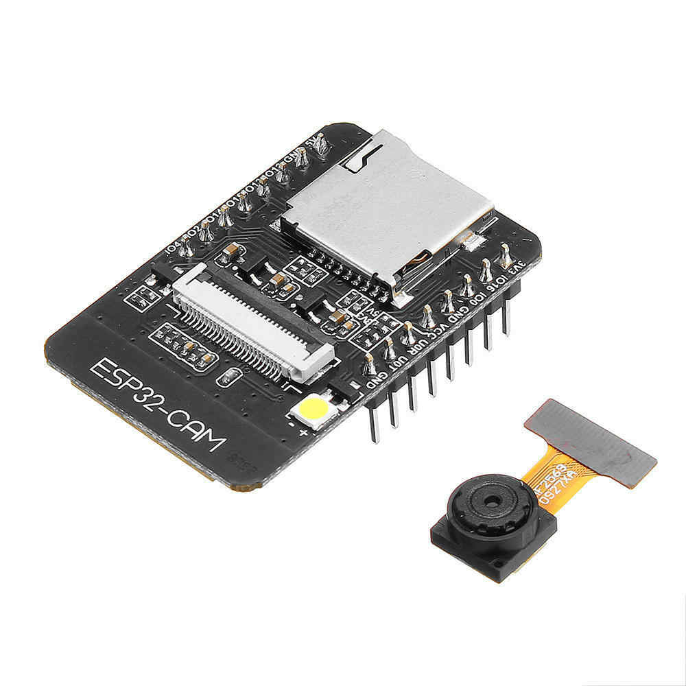
В этой статье речь пойдет об интересной плате на базе микроконтроллера ESP32. Плата называется ESP32-cam, она необычна тем, что на борту нее есть 2х мегапиксельная камера OV2640. Данную плату можно купить тут: http://ali.pub/3f04uj
Также понадобится usb/ttl преобразователь: http://ali.pub/3f156r
Обычно мощностей микроконтроллера не хватает для того чтоб обрабатывать видео поток. Но данная плата настолько мощная, что вполне себе тянет потоковое видео. Вот краткая табличка сравнения контроллеров ESP32 и ESP8266:
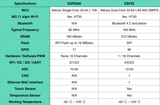
Как видно из таблички ESP32 на голову выше своего младшего брата ESP8266.
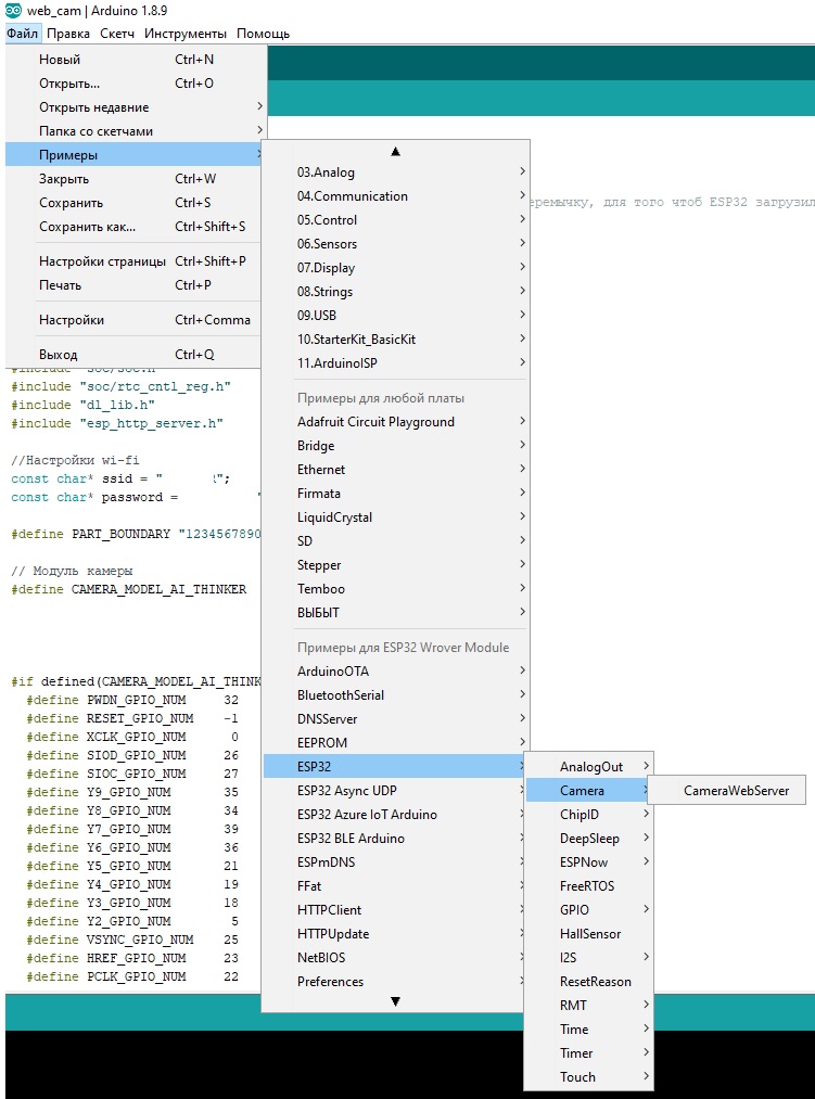
Чтож давайте посмотрим теперь, что же можно сделать с камерой. Если вы установили плату ESP32 в программе arduino ide допустим по моей инструкции, То в стандартных примерах Файл -> примеры -> ESP32 -> camera -> CameraWebServer
В данном примере нам нужно сделать три правки, чтоб камера начала показывать.
Во первых нужно закоментировать одну камеру и раскоментировать другую:
Далее нам нужно ввести SSID нашей wi-fi сети и пароль от нее:
Так как в модуле ESP32-cam нет гнезда под usb кабель, прошивать ее будем через usb/ttl адаптер. Вот схема подключения: 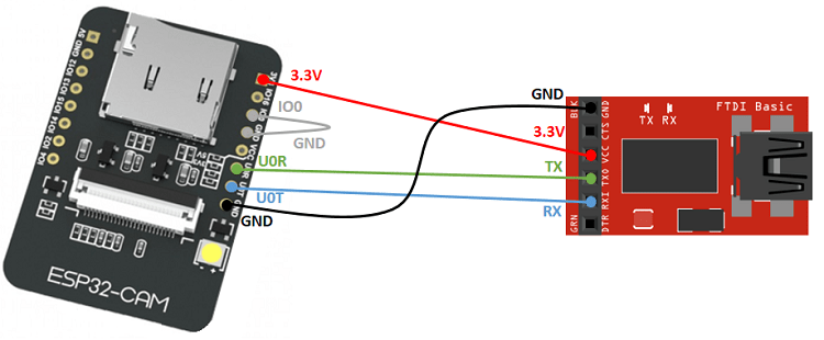
Обратите внимание, что для прошивки обязательно нужно замкнуть контакт IO0 и GND. Это обязательно иначе не зальется прошивка в ESP32. Также для заливки нужно выбрать плату “ESP32 Wrover Module” и Partition Scheme: ” Huge App (3MB no OTA)” . После того как вы все сделали так как я описал, скетч должен залиться без ошибок.
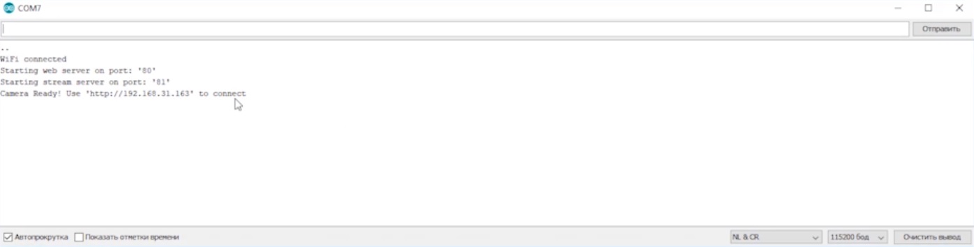
После заливки скетча нужно обязательно убрать перемычку IO0 и GND иначе ESP32 не загрузится в нормальном режиме. Итак включает плату и открываем монитор порта в программе Arduino ide. В мониторе порта должен показаться ip адрес устройства если ESP32 подключилась к wi-fi сети. Выглядит это так:
После этого вводим в браузер данный ip адрес и видим непосредственно настройки камеры и изображение с нее
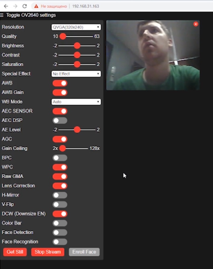
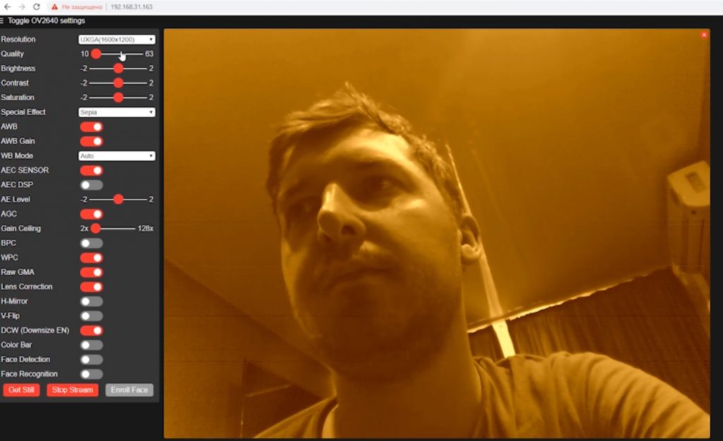
Здесь много всяких настроек нет смысла их описывать. Даже есть распознавание лица, но только почему-то у меня оно не заработало. Если вы думаете, что разрешение камеры слишком маленькое, то его можно увеличить и например сделать оранжевым:
Давайте теперь уберем все лишнее, оставим только воспроизведение видео с камеры, сделаем для нее корпус. И получим самодельную камеру для видеонаблюдения.
Сначала отредактируем скетч, я это конечно же уже сделал, теперь он выглядит так:
В данном скетче нужно указать только SSID wi-fi сети и пароль, остальное уже настроено под данный модуль. Выглядит изображение с него вот так:
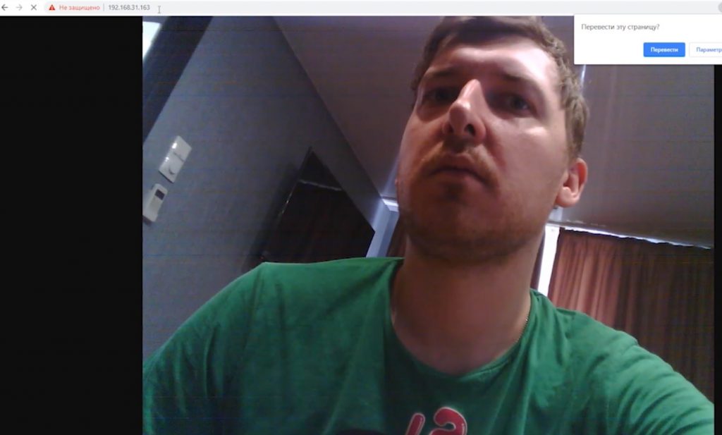
Как видим нет ничего лишнего просто изображение с довольно хорошим разрешением.
Чтож с выводом изображения разобрались, теперь нужно что-то придумать с корпусом. На ум пришла идея купить с Aliexpress муляж камеры и вмонтировать ее туда. Сама камера выглядит вот таким образом, от оригинала не отличить, только внутри пусто: 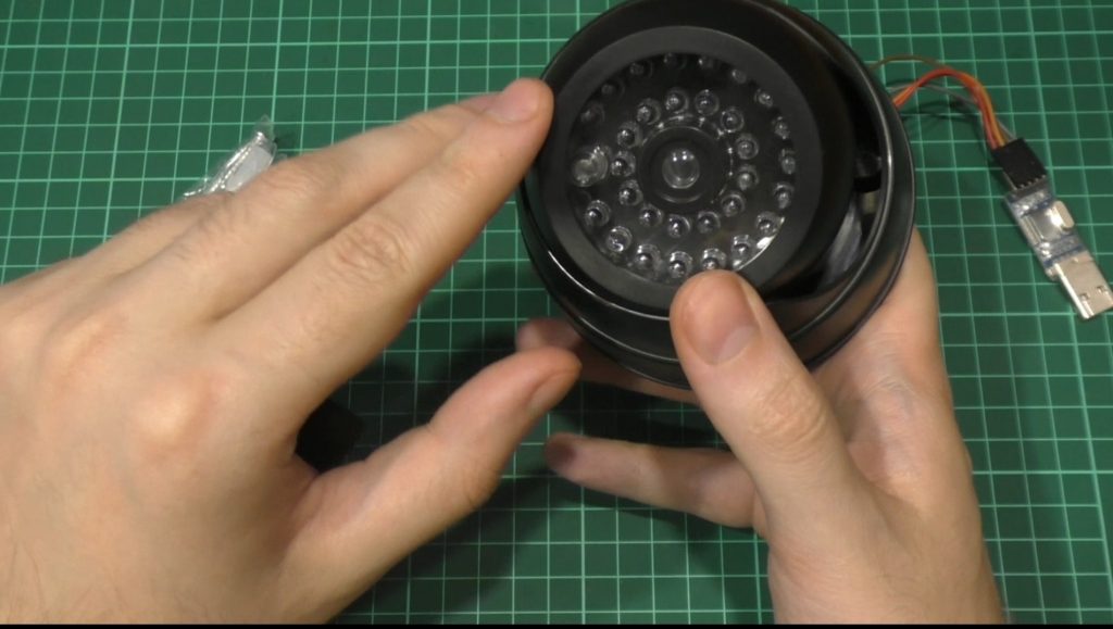
Разбирается камера без усилий, нужно открутить только 3 самореза. Так выглядит разобранный корпус:
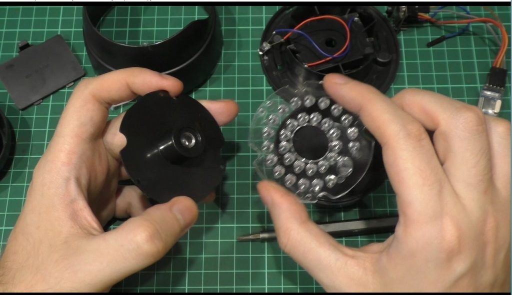
Та часть которая находится в левой руке, к ней и будем крепить нашу камеру, для этого рассверлим отверстие сквозное и приклеим камеру на термоклей.
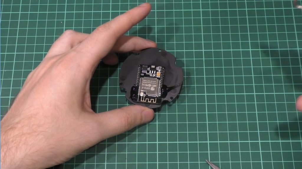
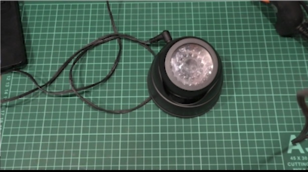
Я нашел блок питания 5В поэтому никаких dc-dc преобразователей ненужно. Так выглядит камера в сборе:
Ну и вот изображение с камеры уже из корпуса :
На этом собственно и все, как по мне так получилось довольно не плохо. Сделали из муляжа настоящую камеру, с которой при желании можно видеть изображение с любой точки планеты. Из минусов только то, что я пока не смог записывать с нее видео. Live стрим есть, а вот просмотреть запись пока нельзя.
Также я все это дело снял на видео и рассказал в нем.
Источник
ESP32-CAM Troubleshooting Guide: Most Common Problems Fixed
After releasing some projects with the ESP32-CAM, some readers reported issues when trying to use the ESP32-CAM. This guide is a compilation with the most common errors when using the ESP32-CAM and how to fix them.

We’ve released the following projects with the ESP32-CAM:
Note: some of our readers reported errors when trying to follow the ESP32-CAM project with Home Assistant. We’ve modified some lines on the code, so most of the problems related with that project should be fixed.
Please note that we couldn’t reproduce some of the errors on our end. However, we’ve gathered all the information given by our readers to get answers to the most common issues.
If you have a different problem or a different solution to these issues, you can share your tips by writing a comment below.
Most common errors:
- Failed to connect to ESP32: Timed out waiting for packet header
- Camera init failed with error 0x20001 or similar
- Brownout detector or Guru meditation error
- Sketch too big error – Wrong partition scheme selected
- Board at COMX is not available – COM Port Not Selected
- Psram error: GPIO isr service is not installed
- Weak Wi-Fi Signal
- No IP Address in Arduino IDE Serial Monitor
- Can’t open web server
- The image lags/shows lots of latency
- esp_camera_fb_get(): Failed to get the frame on time!
1. Failed to connect to ESP32: Timed out waiting for packet header

This error means that the ESP32-CAM is not in flashing mode or it is not connected properly to the FTDI programmer.
Double-check the steps to upload code
Double-check that you’ve followed the exact steps to put your ESP32-CAM in flashing mode. Failing to complete one of the steps may result in that error. Here’s the steps you need to follow:
Connect the ESP32-CAM board to your computer using an FTDI programmer. Follow the next schematic diagram:

Important: GPIO 0 needs to be connected to GND so that you’re able to upload code.
Many FTDI programmers have a jumper that allows you to select 3.3V or 5V. Make sure the jumper is in the right place to select 5V.
Important: GPIO 0 needs to be connected to GND so that you’re able to upload code.
| ESP32-CAM | FTDI Programmer |
| GND | GND |
| 5V | VCC (5V) |
| U0R | TX |
| U0T | RX |
| GPIO 0 | GND |
To upload the code, follow the next steps:
1) Go to Tools > Board and select AI-Thinker ESP32-CAM.
2) Go to Tools > Port and select the COM port the ESP32 is connected to.
3) Then, click the upload button to upload the code.
4) When you start to see these dots on the debugging window as shown below, press the ESP32-CAM on-board RST button.

After a few seconds, the code should be successfully uploaded to your board.
GPIO 0 must be connected to GND
Important: if you can’t upload the code, double-check that GPIO 0 is connected to GND and that you selected the right settings in the Tools menu. You should also press the on-board Reset button to restart your ESP32 in flashing mode. Also, check that you have the FTDI programmer jumper cap set to 5V.
Check the FTDI programmer you are using
One of our readers reported the following: “found out that you can program the board with a USB-to-TTL module model CP2102 and that the CH340 model does NOT work“. This is the FTDI programmer we’re using.
Power the ESP32-CAM with 5V
Some of our readers reported that they could only upload code when the ESP32 was powered with 5V. So, power the ESP32-CAM with 5V.
FTDI Programmer 5V
Measure the output voltage of your FTDI programmer (VCC and GND) using a Multimeter to ensure it’s providing 5V to your ESP32-CAM.

2. Camera init failed with error 0x20001 or similar

If you get this exact error, it means that your camera OVX is not connected properly to your ESP32 board or you have the wrong pin assignment in the code.
Sometimes, unplugging and plugging the FTDI programmer multiple times or restart the board multiple times, might solve the issue.
Camera not connected properly
The camera has a tiny connector and you must ensure it’s connected in the the right away and with a secure fit, otherwise it will fail to establish a connection.
Wrong pin assignment in the code
When you get this error, it might also mean that you didn’t select the right board in the define section or the pin definition is wrong for your board.
Make sure you select the right camera module in your projects. You just need to uncomment the right camera module and comment all the others:
In this example, we’re using the CAMERA_MODEL_AI_THINKER, so it’s the one that is enabled. Otherwise, it will fail the pin assignment and the camera will fail to init.
There are many esp32-cam boards being released (“fake boards”) that the wiring between the ESP32 and the OV camera might be different, so selecting the camera module, might not be enough. You might need to check each gpio declaration with your board pinout.
For example, M5Stack board without PSRAM has a different pin assignment than the M5STACK with PSRAM (defined on the code by default). So, you need to change the pin definition in the code accordingly to the board pinout.
Not enough power through USB source
If you’re powering your ESP32 through a USB port on your computer, it might not be supplying enough power.
Faulty FTDI programmer
Some readers also reported this problem was solved by replacing their actual FTDI programmer with this one.
The camera/connector is broken
If you get this error, it might also mean that your camera or the camera ribbon is broken. If that is the case, you may get a new OV2640 camera probe.
3. Brownout detector or Guru meditation error
When you open your Arduino IDE Serial monitor and the error message “Brownout detector was triggered” is constantly being printed over and over again. It means that there’s some sort of hardware problem.
It’s often related to one of the following issues:
- Poor quality USB cable;
- USB cable is too long;
- Board with some defect (bad solder joints);
- Bad computer USB port;
- Or not enough power provided by the computer USB port.
Solution:
- try a different shorter USB cable (with data wires)
- use a different computer USB port or use a USB hub with an external power supply
- some readers reported that when powering the ESP32-CAM with 5V, the issue was fixed.
Also, follow the suggestions described in issue 2.
4. Sketch too big error – Wrong partition scheme selected

When you get the following error:
It means that you haven’t selected the right partition scheme. Make sure you select the right partition scheme. In your Arduino IDE, go to Tools > Partition Scheme, select “Huge APP (3MB No OTA)“.

If you get the following error or similar:
It means that you haven’t selected the COM port in the Tools menu. In your Arduino IDE, go to Tools > Port and select the COM port the ESP32 is connected to.
It might also mean that the ESP32-CAM is not establishing a serial connection with your computer or it is not properly connected to the USB connector.
6. Psram error: GPIO isr service is not installed

You are using a board without PSRAM and you get the following error or similar:
when the board was initialized with the following settings:
Adding the following fixes the issues (it lowers the image resolution so it won’t need so much space to store images. However, as a result, you cannot get some high resolution formats due to the limited memory):
Note: face recognition and detection doesn’t work with boards without PSRAM. However, you can still use all the other functionalities of the board. For example, although you can’t use the face recognition and detection features of this project (ESP32-CAM Video Streaming and Face Recognition with Arduino IDE), you can still play with the example and explore the board features as long as you have the right pin assignment in the code.
7. Weak Wi-Fi Signal
Some readers reported that after powering the ESP32-CAM with 5V, they’ve gotten a more stable Wi-Fi signal. You can read this dedicated guide to learn how to connect an external antenna to the ESP32-CAM and extend Wi-Fi coverage.
The ESP32-CAM has the option to use either the built-in antenna or an external antenna. If your ESP32-CAM AI-Thinker has no Wi-Fi connection or poor connection, it might have the external antenna enabled. If you connect an external antenna to the connector, it should work fine.
Check if the jumper 0K resistor by the antenna connector is in the proper position for the desired antenna. There are 3 little white squares laid out like a “  Photo courtesy of Helmut Schoenborn
The following photo shows a closer look at that area. You can clearly see a small 0K resistor connecting to the built-in antenna.
 Photo courtesy of Helmut Schoenborn
With board turned so the the PCB antenna is up:
- To use the PCB antenna, the resistor must be on the top position, like this: /
- For the antenna connector, the resistor must be on the bottom position, like this:
So, to enable the on-board antenna:
- Unsolder the resistor that goes to the antenna, it’s in this position
- And solder together the two connections to enable the on-board antenna.
8. No IP Address in Arduino IDE Serial Monitor
f you just see dots printed in the serial monitor (……), it means that your ESP32-CAM is not establishing a Wi-Fi connection with your router.
Double-check your network credentials
You need to make sure that you’ve typed your exact network credentials (SSID and password) in the following variables:
Select the right baud rate in the Arduino IDE Serial Monitor
If you don’t select the right baud rate in the Arduino IDE Serial Monitor, you won’t get your board IP address or you’ll just get garbage on the screen.
Make sure you select the right baud rate. In our examples with the ESP32-CAM, we use 115200 baud rate.
Reset the board multiple times
You might also need to press the ESP32-CAM on-board RESET button multiple times to restart your ESP and print the IP address during boot.
RX and TX swapped
Double-check the connections between your ESP32 board and the FTDI programmer. RX goes to TX and TX goes to RX. If these connections are swapped, the ESP32-CAM is not able to establish a serial communication with your computer.
Wi-Fi Range
If the router is far away from your ESP32 board, it might not be able to catch the Wi-Fi signal. Ensure that your ESP32-CAM is fairly close to your router.
9. Can’t open web server
If the ESP32-CAM is printing the IP address in your Arduino IDE Serial Monitor, but when you try to open the web server in your web browser you see a blank screen, it usually means that you are trying to access the ESP32-CAM web server with multiple web browser tabs.
At the moment, these ESP32-CAM sketches only work with one client connected at a time.
10. The image lags/shows lots of latency
Having some latency is normal for such a small and cheap camera. Some readers have suggested the following to reduce latency:
- Power the ESP32-CAM with a standalone 5V power supply
- Reduce the frame size with the following in your code:
config.frame_size = FRAMESIZE_SVGA or config.frame_size = FRAMESIZE_VGA - Use an external antenna.
11. esp_camera_fb_get(): Failed to get the frame on time!
We’ve personally never faced this issue. However, many readers are getting this error with their ESP32-CAM boards.
One of our readers (Fibula) suggested the following to solve this issue:
“Im using the ESP32-CAM Module 2MP OV2640 Camera sensor Module Type-C USB module from Aliexpress. Although not mentioned, It doesn’t have the extra PSRAM the other M5 models do, and the camera has one changed IO pin.
The CameraWebServer Arduino example we’re probably all using doesn’t have this ESP32-CAM model defined.
You need to add it yourself in the main tab add:
And in the camera_pins.h tab add the following:
And you’re good to go.
Also note that the max resolution of the bare ESP32-CAM Module is XGA 1024×768, I assume also because of the lack of PSRAM. “
Using larger microSD card sizes
According to he datasheet, the ESP32-CAM should only supports 4GB microSD cards.
However, we’ve tested with 16GB microSD card and it works well.
You might not be able to store more than 4GB, even though you have 16GB. We haven’t tested storing more than 4GB, so we’re not sure about this.
Are these projects compatible with M5Stack board?
Yes, the M5Stack ESP32 board is compatible with out projects. However, you must check your camera pinout to ensure you have the right assignment in the code.
You can check the M5Stack camera connections here.
How to set a fixed the IP Address
To set a static/fixed IP address, you can follow the next tutorial:
Setting ESP32-CAM as Access Point (AP)
You can set your ESP32-CAM as an Access Point (AP). This means you are able to connect to your ESP32-CAM directly without having to connect to your router. You can use the following code to set your video streaming web server as an Access Point:
To better understand how it works, you can read the next tutorial:
Learn how to program and build 17 projects with the ESP32-CAM using Arduino IDE DOWNLOAD »
Wrapping Up
We hope you’ve found this troubleshooting guide useful and you were able to make your ESP32-CAM work with our projects.
Источник
After releasing some projects with the ESP32-CAM, some readers reported issues when trying to use the ESP32-CAM. This guide is a compilation with the most common errors when using the ESP32-CAM and how to fix them.

We’ve released the following projects with the ESP32-CAM:
- Video Streaming, Face Detection and Face Recognition
- ESP32 IP CAM – Video Streaming (Home Assistant and Node-RED)
- Take Photo and Save to MicroSD Card
- PIR Motion Detector with Photo Capture
- Take Photo, Save to SPIFFS and Display in Web Server
Note: some of our readers reported errors when trying to follow the ESP32-CAM project with Home Assistant. We’ve modified some lines on the code, so most of the problems related with that project should be fixed.
Please note that we couldn’t reproduce some of the errors on our end. However, we’ve gathered all the information given by our readers to get answers to the most common issues.
If you have a different problem or a different solution to these issues, you can share your tips by writing a comment below.
Most common errors:
- Failed to connect to ESP32: Timed out waiting for packet header
- Camera init failed with error 0x20001 or similar
- Brownout detector or Guru meditation error
- Sketch too big error – Wrong partition scheme selected
- Board at COMX is not available – COM Port Not Selected
- Psram error: GPIO isr service is not installed
- Weak Wi-Fi Signal
- No IP Address in Arduino IDE Serial Monitor
- Can’t open web server
- The image lags/shows lots of latency
- esp_camera_fb_get(): Failed to get the frame on time!
1. Failed to connect to ESP32: Timed out waiting for packet header

This error means that the ESP32-CAM is not in flashing mode or it is not connected properly to the FTDI programmer.
Double-check the steps to upload code
Double-check that you’ve followed the exact steps to put your ESP32-CAM in flashing mode. Failing to complete one of the steps may result in that error. Here’s the steps you need to follow:
Connect the ESP32-CAM board to your computer using an FTDI programmer. Follow the next schematic diagram:

Important: GPIO 0 needs to be connected to GND so that you’re able to upload code.
Many FTDI programmers have a jumper that allows you to select 3.3V or 5V. Make sure the jumper is in the right place to select 5V.
Important: GPIO 0 needs to be connected to GND so that you’re able to upload code.
| ESP32-CAM | FTDI Programmer |
| GND | GND |
| 5V | VCC (5V) |
| U0R | TX |
| U0T | RX |
| GPIO 0 | GND |
To upload the code, follow the next steps:
1) Go to Tools > Board and select AI-Thinker ESP32-CAM.
2) Go to Tools > Port and select the COM port the ESP32 is connected to.
3) Then, click the upload button to upload the code.
4) When you start to see these dots on the debugging window as shown below, press the ESP32-CAM on-board RST button.

After a few seconds, the code should be successfully uploaded to your board.
GPIO 0 must be connected to GND
Important: if you can’t upload the code, double-check that GPIO 0 is connected to GND and that you selected the right settings in the Tools menu. You should also press the on-board Reset button to restart your ESP32 in flashing mode. Also, check that you have the FTDI programmer jumper cap set to 5V.
Check the FTDI programmer you are using
One of our readers reported the following: “found out that you can program the board with a USB-to-TTL module model CP2102 and that the CH340 model does NOT work“. This is the FTDI programmer we’re using.
Power the ESP32-CAM with 5V
Some of our readers reported that they could only upload code when the ESP32 was powered with 5V. So, power the ESP32-CAM with 5V.
FTDI Programmer 5V
Measure the output voltage of your FTDI programmer (VCC and GND) using a Multimeter to ensure it’s providing 5V to your ESP32-CAM.

2. Camera init failed with error 0x20001 or similar

If you get this exact error, it means that your camera OVX is not connected properly to your ESP32 board or you have the wrong pin assignment in the code.
Sometimes, unplugging and plugging the FTDI programmer multiple times or restart the board multiple times, might solve the issue.
Camera not connected properly
The camera has a tiny connector and you must ensure it’s connected in the the right away and with a secure fit, otherwise it will fail to establish a connection.
Wrong pin assignment in the code
When you get this error, it might also mean that you didn’t select the right board in the define section or the pin definition is wrong for your board.
Make sure you select the right camera module in your projects. You just need to uncomment the right camera module and comment all the others:
//#define CAMERA_MODEL_WROVER_KIT
//#define CAMERA_MODEL_M5STACK_PSRAM
#define CAMERA_MODEL_AI_THINKER
In this example, we’re using the CAMERA_MODEL_AI_THINKER, so it’s the one that is enabled. Otherwise, it will fail the pin assignment and the camera will fail to init.
There are many esp32-cam boards being released (“fake boards”) that the wiring between the ESP32 and the OV camera might be different, so selecting the camera module, might not be enough. You might need to check each gpio declaration with your board pinout.
For example, M5Stack board without PSRAM has a different pin assignment than the M5STACK with PSRAM (defined on the code by default). So, you need to change the pin definition in the code accordingly to the board pinout.
Not enough power through USB source
If you’re powering your ESP32 through a USB port on your computer, it might not be supplying enough power.
Faulty FTDI programmer
Some readers also reported this problem was solved by replacing their actual FTDI programmer with this one.
The camera/connector is broken
If you get this error, it might also mean that your camera or the camera ribbon is broken. If that is the case, you may get a new OV2640 camera probe.
3. Brownout detector or Guru meditation error
When you open your Arduino IDE Serial monitor and the error message “Brownout detector was triggered” is constantly being printed over and over again. It means that there’s some sort of hardware problem.
It’s often related to one of the following issues:
- Poor quality USB cable;
- USB cable is too long;
- Board with some defect (bad solder joints);
- Bad computer USB port;
- Or not enough power provided by the computer USB port.
Solution:
- try a different shorter USB cable (with data wires)
- use a different computer USB port or use a USB hub with an external power supply
- some readers reported that when powering the ESP32-CAM with 5V, the issue was fixed.
Also, follow the suggestions described in issue 2.
4. Sketch too big error – Wrong partition scheme selected

When you get the following error:
Sketch too big; see http://www.arduino.cc/en/Guide/Troubleshooting#size for tips on reducing it.
Error compiling for board ESP32 Dev Module.
It means that you haven’t selected the right partition scheme. Make sure you select the right partition scheme. In your Arduino IDE, go to Tools > Partition Scheme, select “Huge APP (3MB No OTA)“.
5. Board at COMX is not available – COM Port Not Selected

If you get the following error or similar:
serial.serialutil.SerialException: could not open port 'COM8': WindowsError(2, 'The system cannot find the file specified.')
Failed to execute script esptool
the selected serial port Failed to execute script esptool
 does not exist or your board is not connected
Board at COM8 is not available
It means that you haven’t selected the COM port in the Tools menu. In your Arduino IDE, go to Tools > Port and select the COM port the ESP32 is connected to.
It might also mean that the ESP32-CAM is not establishing a serial connection with your computer or it is not properly connected to the USB connector.
6. Psram error: GPIO isr service is not installed

You are using a board without PSRAM and you get the following error or similar:
E (161) gpio: gpio_isr_handler_remove(380): GPIO isr service is not installed, call gpio_install_isr_service() first
Camera init failed with error 0x101
when the board was initialized with the following settings:
config.frame_size = FRAMESIZE_UXGA;
config.jpeg_quality = 10;
config.fb_count = 2;
Adding the following fixes the issues (it lowers the image resolution so it won’t need so much space to store images. However, as a result, you cannot get some high resolution formats due to the limited memory):
if(psramFound()){
  config.frame_size = FRAMESIZE_UXGA;
  config.jpeg_quality = 10;
  config.fb_count = 2;
} else {
  config.frame_size = FRAMESIZE_SVGA;
  config.jpeg_quality = 12;
  config.fb_count = 1;
}
Note: face recognition and detection doesn’t work with boards without PSRAM. However, you can still use all the other functionalities of the board. For example, although you can’t use the face recognition and detection features of this project (ESP32-CAM Video Streaming and Face Recognition with Arduino IDE), you can still play with the example and explore the board features as long as you have the right pin assignment in the code.
7. Weak Wi-Fi Signal
Some readers reported that after powering the ESP32-CAM with 5V, they’ve gotten a more stable Wi-Fi signal. You can read this dedicated guide to learn how to connect an external antenna to the ESP32-CAM and extend Wi-Fi coverage.
The ESP32-CAM has the option to use either the built-in antenna or an external antenna. If your ESP32-CAM AI-Thinker has no Wi-Fi connection or poor connection, it might have the external antenna enabled. If you connect an external antenna to the connector, it should work fine.
Check if the jumper 0K resistor by the antenna connector is in the proper position for the desired antenna. There are 3 little white squares laid out like a “<” with the middle position being common.

The following photo shows a closer look at that area. You can clearly see a small 0K resistor connecting to the built-in antenna.

With board turned so the the PCB antenna is up:
- To use the PCB antenna, the resistor must be on the top position, like this: /
- For the antenna connector, the resistor must be on the bottom position, like this:
So, to enable the on-board antenna:
- Unsolder the resistor that goes to the antenna, it’s in this position
- And solder together the two connections to enable the on-board antenna.
8. No IP Address in Arduino IDE Serial Monitor
f you just see dots printed in the serial monitor (……), it means that your ESP32-CAM is not establishing a Wi-Fi connection with your router.
Double-check your network credentials
You need to make sure that you’ve typed your exact network credentials (SSID and password) in the following variables:
const char* ssid = "REPLACE_WITH_YOUR_SSID";
const char* password = "REPLACE_WITH_YOUR_PASSWORD";
Select the right baud rate in the Arduino IDE Serial Monitor
If you don’t select the right baud rate in the Arduino IDE Serial Monitor, you won’t get your board IP address or you’ll just get garbage on the screen.
Make sure you select the right baud rate. In our examples with the ESP32-CAM, we use 115200 baud rate.
Reset the board multiple times
You might also need to press the ESP32-CAM on-board RESET button multiple times to restart your ESP and print the IP address during boot.
RX and TX swapped
Double-check the connections between your ESP32 board and the FTDI programmer. RX goes to TX and TX goes to RX. If these connections are swapped, the ESP32-CAM is not able to establish a serial communication with your computer.
Wi-Fi Range
If the router is far away from your ESP32 board, it might not be able to catch the Wi-Fi signal. Ensure that your ESP32-CAM is fairly close to your router.
9. Can’t open web server
If the ESP32-CAM is printing the IP address in your Arduino IDE Serial Monitor, but when you try to open the web server in your web browser you see a blank screen, it usually means that you are trying to access the ESP32-CAM web server with multiple web browser tabs.
At the moment, these ESP32-CAM sketches only work with one client connected at a time.
10. The image lags/shows lots of latency
Having some latency is normal for such a small and cheap camera. Some readers have suggested the following to reduce latency:
- Power the ESP32-CAM with a standalone 5V power supply
- Reduce the frame size with the following in your code:
config.frame_size = FRAMESIZE_SVGA or config.frame_size = FRAMESIZE_VGA - Use an external antenna.
11. esp_camera_fb_get(): Failed to get the frame on time!
We’ve personally never faced this issue. However, many readers are getting this error with their ESP32-CAM boards.
One of our readers (Fibula) suggested the following to solve this issue:
“Im using the ESP32-CAM Module 2MP OV2640 Camera sensor Module Type-C USB module from Aliexpress. Although not mentioned, It doesn’t have the extra PSRAM the other M5 models do, and the camera has one changed IO pin.
See here: https://github.com/m5stack/m5stack-cam-psram/blob/master/README.md and scroll down to Interface Comparison.
The CameraWebServer Arduino example we’re probably all using doesn’t have this ESP32-CAM model defined.
You need to add it yourself in the main tab add:
#define CAMERA_MODEL_M5STACK_NO_PSRAMAnd in the camera_pins.h tab add the following:
#elif defined(CAMERA_MODEL_M5STACK_NO_PSRAM)
#define PWDN_GPIO_NUM -1
#define RESET_GPIO_NUM 15
#define XCLK_GPIO_NUM 27
#define SIOD_GPIO_NUM 25
#define SIOC_GPIO_NUM 23
#define Y9_GPIO_NUM 19
#define Y8_GPIO_NUM 36
#define Y7_GPIO_NUM 18
#define Y6_GPIO_NUM 39
#define Y5_GPIO_NUM 5
#define Y4_GPIO_NUM 34
#define Y3_GPIO_NUM 35
#define Y2_GPIO_NUM 17
#define VSYNC_GPIO_NUM 22
#define HREF_GPIO_NUM 26
#define PCLK_GPIO_NUM 21
And you’re good to go.
Also note that the max resolution of the bare ESP32-CAM Module is XGA 1024×768, I assume also because of the lack of PSRAM. “
We hope this suggestion solves your issue. Let us know in the comments section.
Using larger microSD card sizes
According to he datasheet, the ESP32-CAM should only supports 4GB microSD cards.
However, we’ve tested with 16GB microSD card and it works well.
You might not be able to store more than 4GB, even though you have 16GB. We haven’t tested storing more than 4GB, so we’re not sure about this.
Are these projects compatible with M5Stack board?
Yes, the M5Stack ESP32 board is compatible with out projects. However, you must check your camera pinout to ensure you have the right assignment in the code.
You can check the M5Stack camera connections here.
How to set a fixed the IP Address
To set a static/fixed IP address, you can follow the next tutorial:
- ESP32 Static/Fixed IP Address
Setting ESP32-CAM as Access Point (AP)
You can set your ESP32-CAM as an Access Point (AP). This means you are able to connect to your ESP32-CAM directly without having to connect to your router. You can use the following code to set your video streaming web server as an Access Point:
/*********
  Rui Santos
  Complete project details at https://RandomNerdTutorials.com/esp32-cam-video-streaming-web-server-camera-home-assistant/

  IMPORTANT!!!
   - Select Board "AI Thinker ESP32-CAM"
   - GPIO 0 must be connected to GND to upload a sketch
   - After connecting GPIO 0 to GND, press the ESP32-CAM on-board RESET button to put your board in flashing mode

  Permission is hereby granted, free of charge, to any person obtaining a copy
  of this software and associated documentation files.

  The above copyright notice and this permission notice shall be included in all
  copies or substantial portions of the Software.
*********/

#include "esp_camera.h"
#include <WiFi.h>
#include "esp_timer.h"
#include "img_converters.h"
#include "Arduino.h"
#include "fb_gfx.h"
#include "soc/soc.h" //disable brownout problems
#include "soc/rtc_cntl_reg.h"  //disable brownout problems
#include "esp_http_server.h"

// Replace with your network credentials
const char* ssid     = "ESP32-Access-Point";
const char* password = "123456789";

#define PART_BOUNDARY "123456789000000000000987654321"

// This project was tested with the AI Thinker Model, M5STACK PSRAM Model and M5STACK WITHOUT PSRAM
#define CAMERA_MODEL_AI_THINKER
//#define CAMERA_MODEL_M5STACK_PSRAM
//#define CAMERA_MODEL_M5STACK_WITHOUT_PSRAM

// Not tested with this model
//#define CAMERA_MODEL_WROVER_KIT

#if defined(CAMERA_MODEL_WROVER_KIT)
  #define PWDN_GPIO_NUM    -1
  #define RESET_GPIO_NUM   -1
  #define XCLK_GPIO_NUM    21
  #define SIOD_GPIO_NUM    26
  #define SIOC_GPIO_NUM    27

  #define Y9_GPIO_NUM      35
  #define Y8_GPIO_NUM      34
  #define Y7_GPIO_NUM      39
  #define Y6_GPIO_NUM      36
  #define Y5_GPIO_NUM      19
  #define Y4_GPIO_NUM      18
  #define Y3_GPIO_NUM       5
  #define Y2_GPIO_NUM       4
  #define VSYNC_GPIO_NUM   25
  #define HREF_GPIO_NUM    23
  #define PCLK_GPIO_NUM    22

#elif defined(CAMERA_MODEL_M5STACK_PSRAM)
  #define PWDN_GPIO_NUM     -1
  #define RESET_GPIO_NUM    15
  #define XCLK_GPIO_NUM     27
  #define SIOD_GPIO_NUM     25
  #define SIOC_GPIO_NUM     23

  #define Y9_GPIO_NUM       19
  #define Y8_GPIO_NUM       36
  #define Y7_GPIO_NUM       18
  #define Y6_GPIO_NUM       39
  #define Y5_GPIO_NUM        5
  #define Y4_GPIO_NUM       34
  #define Y3_GPIO_NUM       35
  #define Y2_GPIO_NUM       32
  #define VSYNC_GPIO_NUM    22
  #define HREF_GPIO_NUM     26
  #define PCLK_GPIO_NUM     21

#elif defined(CAMERA_MODEL_M5STACK_WITHOUT_PSRAM)
  #define PWDN_GPIO_NUM     -1
  #define RESET_GPIO_NUM    15
  #define XCLK_GPIO_NUM     27
  #define SIOD_GPIO_NUM     25
  #define SIOC_GPIO_NUM     23

  #define Y9_GPIO_NUM       19
  #define Y8_GPIO_NUM       36
  #define Y7_GPIO_NUM       18
  #define Y6_GPIO_NUM       39
  #define Y5_GPIO_NUM        5
  #define Y4_GPIO_NUM       34
  #define Y3_GPIO_NUM       35
  #define Y2_GPIO_NUM       17
  #define VSYNC_GPIO_NUM    22
  #define HREF_GPIO_NUM     26
  #define PCLK_GPIO_NUM     21

#elif defined(CAMERA_MODEL_AI_THINKER)
  #define PWDN_GPIO_NUM     32
  #define RESET_GPIO_NUM    -1
  #define XCLK_GPIO_NUM      0
  #define SIOD_GPIO_NUM     26
  #define SIOC_GPIO_NUM     27

  #define Y9_GPIO_NUM       35
  #define Y8_GPIO_NUM       34
  #define Y7_GPIO_NUM       39
  #define Y6_GPIO_NUM       36
  #define Y5_GPIO_NUM       21
  #define Y4_GPIO_NUM       19
  #define Y3_GPIO_NUM       18
  #define Y2_GPIO_NUM        5
  #define VSYNC_GPIO_NUM    25
  #define HREF_GPIO_NUM     23
  #define PCLK_GPIO_NUM     22
#else
  #error "Camera model not selected"
#endif

static const char* _STREAM_CONTENT_TYPE = "multipart/x-mixed-replace;boundary=" PART_BOUNDARY;
static const char* _STREAM_BOUNDARY = "rn--" PART_BOUNDARY "rn";
static const char* _STREAM_PART = "Content-Type: image/jpegrnContent-Length: %urnrn";

httpd_handle_t stream_httpd = NULL;

static esp_err_t stream_handler(httpd_req_t *req){
  camera_fb_t * fb = NULL;
  esp_err_t res = ESP_OK;
  size_t _jpg_buf_len = 0;
  uint8_t * _jpg_buf = NULL;
  char * part_buf[64];

  res = httpd_resp_set_type(req, _STREAM_CONTENT_TYPE);
  if(res != ESP_OK){
    return res;
  }

  while(true){
    fb = esp_camera_fb_get();
    if (!fb) {
      Serial.println("Camera capture failed");
      res = ESP_FAIL;
    } else {
      if(fb->width > 400){
        if(fb->format != PIXFORMAT_JPEG){
          bool jpeg_converted = frame2jpg(fb, 80, &_jpg_buf, &_jpg_buf_len);
          esp_camera_fb_return(fb);
          fb = NULL;
          if(!jpeg_converted){
            Serial.println("JPEG compression failed");
            res = ESP_FAIL;
          }
        } else {
          _jpg_buf_len = fb->len;
          _jpg_buf = fb->buf;
        }
      }
    }
    if(res == ESP_OK){
      size_t hlen = snprintf((char *)part_buf, 64, _STREAM_PART, _jpg_buf_len);
      res = httpd_resp_send_chunk(req, (const char *)part_buf, hlen);
    }
    if(res == ESP_OK){
      res = httpd_resp_send_chunk(req, (const char *)_jpg_buf, _jpg_buf_len);
    }
    if(res == ESP_OK){
      res = httpd_resp_send_chunk(req, _STREAM_BOUNDARY, strlen(_STREAM_BOUNDARY));
    }
    if(fb){
      esp_camera_fb_return(fb);
      fb = NULL;
      _jpg_buf = NULL;
    } else if(_jpg_buf){
      free(_jpg_buf);
      _jpg_buf = NULL;
    }
    if(res != ESP_OK){
      break;
    }
    //Serial.printf("MJPG: %uBn",(uint32_t)(_jpg_buf_len));
  }
  return res;
}

void startCameraServer(){
  httpd_config_t config = HTTPD_DEFAULT_CONFIG();
  config.server_port = 80;

  httpd_uri_t index_uri = {
    .uri       = "/",
    .method    = HTTP_GET,
    .handler   = stream_handler,
    .user_ctx  = NULL
  };

  //Serial.printf("Starting web server on port: '%d'n", config.server_port);
  if (httpd_start(&stream_httpd, &config) == ESP_OK) {
    httpd_register_uri_handler(stream_httpd, &index_uri);
  }
}

void setup() {
  WRITE_PERI_REG(RTC_CNTL_BROWN_OUT_REG, 0); //disable brownout detector

  Serial.begin(115200);
  Serial.setDebugOutput(false);

  camera_config_t config;
  config.ledc_channel = LEDC_CHANNEL_0;
  config.ledc_timer = LEDC_TIMER_0;
  config.pin_d0 = Y2_GPIO_NUM;
  config.pin_d1 = Y3_GPIO_NUM;
  config.pin_d2 = Y4_GPIO_NUM;
  config.pin_d3 = Y5_GPIO_NUM;
  config.pin_d4 = Y6_GPIO_NUM;
  config.pin_d5 = Y7_GPIO_NUM;
  config.pin_d6 = Y8_GPIO_NUM;
  config.pin_d7 = Y9_GPIO_NUM;
  config.pin_xclk = XCLK_GPIO_NUM;
  config.pin_pclk = PCLK_GPIO_NUM;
  config.pin_vsync = VSYNC_GPIO_NUM;
  config.pin_href = HREF_GPIO_NUM;
  config.pin_sscb_sda = SIOD_GPIO_NUM;
  config.pin_sscb_scl = SIOC_GPIO_NUM;
  config.pin_pwdn = PWDN_GPIO_NUM;
  config.pin_reset = RESET_GPIO_NUM;
  config.xclk_freq_hz = 20000000;
  config.pixel_format = PIXFORMAT_JPEG;

  if(psramFound()){
    config.frame_size = FRAMESIZE_UXGA;
    config.jpeg_quality = 10;
    config.fb_count = 2;
  } else {
    config.frame_size = FRAMESIZE_SVGA;
    config.jpeg_quality = 12;
    config.fb_count = 1;
  }

  // Camera init
  esp_err_t err = esp_camera_init(&config);
  if (err != ESP_OK) {
    Serial.printf("Camera init failed with error 0x%x", err);
    return;
  }
  // Connect to Wi-Fi network with SSID and password
  Serial.print("Setting AP (Access Point)…");
  // Remove the password parameter, if you want the AP (Access Point) to be open
  WiFi.softAP(ssid, password);

  IPAddress IP = WiFi.softAPIP();
  Serial.print("Camera Stream Ready! Connect to the ESP32 AP and go to: http://");
  Serial.println(IP);

  // Start streaming web server
  startCameraServer();
}

void loop() {
  delay(1);
}
View raw code
To better understand how it works, you can read the next tutorial:
- ESP32 Access Point (AP) for Web Server
Wrapping Up
We hope you’ve found this troubleshooting guide useful and you were able to make your ESP32-CAM work with our projects.
If you have any other issues or suggestions on how to fix them, please post a comment below.
If you like this project, you may also like other projects with the ESP32-CAM:
- ESP32-CAM AI-Thinker Pinout Guide: GPIOs Usage Explained
- Video Streaming, Face Detection and Face Recognition
- Build ESP32-CAM Projects (eBook)
- Read all our ESP32-CAM Projects, Tutorials and Guides
Thank you for reading.
P.S. It is very difficult to understand what’s wrong with your project when we can’t reproduce the error on our end. However, if you post the error, there might be other readers with the same issue/solution, so we encourage you to interact in the comment’s section.
New issue
Have a question about this project? Sign up for a free GitHub account to open an issue and contact its maintainers and the community.
By clicking “Sign up for GitHub”, you agree to our terms of service and
privacy statement. We’ll occasionally send you account related emails.
Already on GitHub?
Sign in
to your account
Closed
JanBosNL opened this issue
Mar 19, 2019
· 4 comments
Comments
![]()
I bought the cheap 9$ ESP32-CAM board from alixpress
After searching and lots of reading I discovered its this board -> www.ai-thinker.com/esp32-cam
When I try and flash this board I get the following error.
SCCB_Write [23]=00 failed
E (740) camera: Failed to set frame size
E (740) camera: Camera init failed with error 0x20002
E (740) app_camera: Camera init failed with error 0x20002
I did get this Board with AF2569 camera module working with another project here on github https://github.com/donny681/ESP32_CAMERA_QR
Any suggestions how to be able to get esp-who working?
This is what I received through my make monitor
HP@5574cc35 MINGW32 ~/esp/esp-who/examples/single_chip/camera_web_server
$ make flash
Toolchain path: /opt/xtensa-esp32-elf/bin/xtensa-esp32-elf-gcc
Toolchain version: crosstool-ng-1.22.0-80-g6c4433a5
Compiler version: 5.2.0
Python requirements from C:/msys32/home/HP/esp/esp-idf/requirements.txt are satisfied.
App «camera_web_server» version: v0.9.1-15-g123ce3b
Flashing binaries to serial port COM5 (app at offset 0x10000)…
esptool.py v2.6
Serial port COM5
Connecting….
Chip is ESP32D0WDQ5 (revision 1)
Features: WiFi, BT, Dual Core, 240MHz, VRef calibration in efuse, Coding Scheme None
MAC: 24:0a:c4:ba:9f:1c
Uploading stub…
Running stub…
Stub running…
Changing baud rate to 921600
Changed.
Configuring flash size…
Auto-detected Flash size: 4MB
Compressed 26432 bytes to 15743…
Wrote 26432 bytes (15743 compressed) at 0x00001000 in 0.2 seconds (effective 1033.4 kbit/s)…
Hash of data verified.
Compressed 2250400 bytes to 1797823…
Wrote 2250400 bytes (1797823 compressed) at 0x00010000 in 24.6 seconds (effective 731.2 kbit/s)…
Hash of data verified.
Compressed 3072 bytes to 88…
Wrote 3072 bytes (88 compressed) at 0x00008000 in 0.0 seconds (effective 7048.2 kbit/s)…
Hash of data verified.
Leaving…
Hard resetting via RTS pin…
HP@5574cc35 MINGW32 ~/esp/esp-who/examples/single_chip/camera_web_server
$ make monitor
Toolchain path: /opt/xtensa-esp32-elf/bin/xtensa-esp32-elf-gcc
Toolchain version: crosstool-ng-1.22.0-80-g6c4433a5
Compiler version: 5.2.0
Python requirements from C:/msys32/home/HP/esp/esp-idf/requirements.txt are satisfied.
MONITOR
— idf_monitor on COM5 115200 —
— Quit: Ctrl+] | Menu: Ctrl+T | Help: Ctrl+T followed by Ctrl+H —
e.Rչ╔ 8 ╗:22HHH0x1 ]ON_QUIi0x1&BA%_FAe1║MH_Bϊj
confZ֥ 0, *]A0xeC,kE0x00)}:0x0d_d.0,czi0x0bhd_00,w}0x0C닕:DI k dZj
load’,le’SH+0x3fflenj
loa’00780,leK
0x480400
I (28) boot: ESP-IDF v4.0-dev-78-g8fbb63c2a 2nd stage bootloader
I (28) boot: compile time 13:11:30
I (28) boot: Enabling RNG early entropy source…
I (34) qio_mode: Enabling default flash chip QIO
I (39) boot: SPI Speed : 80MHz
I (44) boot: SPI Mode : QIO
I (48) boot: SPI Flash Size : 4MB
I (52) boot: Partition Table:
I (55) boot: ## Label Usage Type ST Offset Length
I (63) boot: 0 factory factory app 00 00 00010000 00300000
I (70) boot: 1 nvs WiFi data 01 02 00310000 00004000
I (78) boot: End of partition table
I (82) esp_image: segment 0: paddr=0x00010020 vaddr=0x3f400020 size=0x17fb5c (1571676) map
I (506) esp_image: segment 1: paddr=0x0018fb84 vaddr=0x3ffb0000 size=0x0048c ( 1164) load
I (507) esp_image: segment 2: paddr=0x00190018 vaddr=0x400d0018 size=0x8c598 (574872) map
0x400d0018: _stext at ??:?
I (665) esp_image: segment 3: paddr=0x0021c5b8 vaddr=0x3ffb048c size=0x02cdc ( 11484) load
I (668) esp_image: segment 4: paddr=0x0021f29c vaddr=0x40080000 size=0x00400 ( 1024) load
0x40080000: _WindowOverflow4 at C:/msys32/home/HP/esp/esp-idf/components/freertos/xtensa_vectors.S:1779
I (672) esp_image: segment 5: paddr=0x0021f6a4 vaddr=0x40080400 size=0x15fcc ( 90060) load
I (723) boot: Loaded app from partition at offset 0x10000
I (723) boot: Disabling RNG early entropy source…
I (724) spiram: Found 64MBit SPI RAM device
I (728) spiram: SPI RAM mode: flash 80m sram 80m
I (733) spiram: PSRAM initialized, cache is in low/high (2-core) mode.
I (740) cpu_start: Pro cpu up.
I (744) cpu_start: Application information:
I (749) cpu_start: Project name: camera_web_server
I (755) cpu_start: App version: v0.9.1-15-g123ce3b
I (761) cpu_start: Compile time: Mar 19 2019 13:11:55
I (767) cpu_start: ELF file SHA256: b705aedb8cf8efed…
I (773) cpu_start: ESP-IDF: v4.0-dev-78-g8fbb63c2a
I (779) cpu_start: Starting app cpu, entry point is 0x40081410
0x40081410: call_start_cpu1 at C:/msys32/home/HP/esp/esp-idf/components/esp32/cpu_start.c:267
I (0) cpu_start: App cpu up.
I (1274) spiram: SPI SRAM memory test OK
I (1274) heap_init: Initializing. RAM available for dynamic allocation:
I (1274) heap_init: At 3FFAE6E0 len 00001920 (6 KiB): DRAM
I (1281) heap_init: At 3FFBC328 len 00023CD8 (143 KiB): DRAM
I (1287) heap_init: At 3FFE0440 len 00003AE0 (14 KiB): D/IRAM
I (1293) heap_init: At 3FFE4350 len 0001BCB0 (111 KiB): D/IRAM
I (1300) heap_init: At 400963CC len 00009C34 (39 KiB): IRAM
I (1306) cpu_start: Pro cpu start user code
I (1311) spiram: Adding pool of 4096K of external SPI memory to heap allocator
I (213) cpu_start: Starting scheduler on PRO CPU.
I (0) cpu_start: Starting scheduler on APP CPU.
I (260) wifi: wifi driver task: 3ffc3d58, prio:23, stack:3584, core=0
I (260) wifi: wifi firmware version: 1f585c4
I (260) wifi: config NVS flash: enabled
I (270) wifi: config nano formating: disabled
I (270) system_api: Base MAC address is not set, read default base MAC address from BLK0 of EFUSE
I (280) system_api: Base MAC address is not set, read default base MAC address from BLK0 of EFUSE
I (300) wifi: Init dynamic tx buffer num: 32
I (310) wifi: Init data frame dynamic rx buffer num: 32
I (310) wifi: Init management frame dynamic rx buffer num: 32
I (310) wifi: Init management short buffer num: 32
I (310) wifi: Init static rx buffer size: 1600
I (320) wifi: Init static rx buffer num: 10
I (320) wifi: Init dynamic rx buffer num: 32
I (340) camera wifi: wifi_init_softap finished.SSID:ESP32-Camera password:
I (340) camera wifi: wifi_init_sta finished.
I (340) camera wifi: connect to ap SSID:FRITZ!Box Fon WLAN 7360 password:67357982247453841495
I (430) phy: phy_version: 4100, 6fa5e27, Jan 25 2019, 17:02:06, 0, 0
I (430) wifi: mode : sta (24:0a:c4:ba:9f:1c) + softAP (24:0a:c4:ba:9f:1d)
I (430) wifi: Init max length of beacon: 752/752
I (430) wifi: Init max length of beacon: 752/752
I (440) gpio: GPIO[32]| InputEn: 0| OutputEn: 1| OpenDrain: 0| Pullup: 0| Pulldown: 0| Intr:0
I (530) gpio: GPIO[35]| InputEn: 1| OutputEn: 0| OpenDrain: 0| Pullup: 1| Pulldown: 0| Intr:0
I (530) gpio: GPIO[34]| InputEn: 1| OutputEn: 0| OpenDrain: 0| Pullup: 1| Pulldown: 0| Intr:0
I (540) gpio: GPIO[39]| InputEn: 1| OutputEn: 0| OpenDrain: 0| Pullup: 1| Pulldown: 0| Intr:0
I (550) gpio: GPIO[36]| InputEn: 1| OutputEn: 0| OpenDrain: 0| Pullup: 1| Pulldown: 0| Intr:0
I (560) gpio: GPIO[21]| InputEn: 1| OutputEn: 0| OpenDrain: 0| Pullup: 1| Pulldown: 0| Intr:0
I (570) gpio: GPIO[19]| InputEn: 1| OutputEn: 0| OpenDrain: 0| Pullup: 1| Pulldown: 0| Intr:0
I (580) gpio: GPIO[18]| InputEn: 1| OutputEn: 0| OpenDrain: 0| Pullup: 1| Pulldown: 0| Intr:0
I (590) gpio: GPIO[5]| InputEn: 1| OutputEn: 0| OpenDrain: 0| Pullup: 1| Pulldown: 0| Intr:0
I (590) gpio: GPIO[25]| InputEn: 1| OutputEn: 0| OpenDrain: 0| Pullup: 1| Pulldown: 0| Intr:0
I (600) gpio: GPIO[23]| InputEn: 1| OutputEn: 0| OpenDrain: 0| Pullup: 1| Pulldown: 0| Intr:0
I (610) gpio: GPIO[22]| InputEn: 1| OutputEn: 0| OpenDrain: 0| Pullup: 1| Pulldown: 0| Intr:0
I (620) camera: Allocating 2 frame buffers (750 KB total)
I (630) camera: Allocating 375 KB frame buffer in PSRAM
I (690) camera: Allocating 375 KB frame buffer in PSRAM
SCCB_Write [23]=00 failed
E (740) camera: Failed to set frame size
E (740) camera: Camera init failed with error 0x20002
E (740) app_camera: Camera init failed with error 0x20002
I (750) camera_httpd: Starting web server on port: ’80’
I (760) camera_httpd: Starting stream server on port: ’81’
I (2880) camera wifi: retry to connect to the AP
I (2880) camera wifi: connect to the AP fail
I (5320) camera wifi: retry to connect to the AP
I (5320) camera wifi: connect to the AP fail
I (7760) camera wifi: retry to connect to the AP
I (7760) camera wifi: connect to the AP fail
I (10200) camera wifi: retry to connect to the AP
I (10200) camera wifi: connect to the AP fail
I (12640) camera wifi: retry to connect to the AP
I (12640) camera wifi: connect to the AP fail
I (15080) camera wifi: connect to the AP fail
![]()
JanBosNL
changed the title
Trying to get ESpp
Trying to get ESP32 AI-Thinker with AF2569 camera module working
Mar 19, 2019
![]()
When using the working code from the github repository https://github.com/donny681/ESP32_CAMERA_QR
I get this when monitoring the ESP32
rst’ (POWERON_RESEUI0x13 (SPI_FP*e1║M!} ==Q
c˥gsip: 0, SPIWP:�
clk_drv:0x00)}rv:0x00,d_drv:00,cs0_drv:0x00,hEv:0x00,wp_drv:00
mode:DIO, clo-«2
load:0x38,len:4
load’fff001c,len:64SH+0x40078000:11308
ho 0 tXZ
room 4
load’0080400,len:67&H0x4008076SHI (30) boot: ESP-IDF v4.0-dev-78-g8fbb63c2a 2nd stage bootloader
I (30) boot: compile time 11:58:46
I (30) boot: Enabling RNG early entropy source…
I (36) boot: SPI Speed : 40MHz
I (40) boot: SPI Mode : DIO
I (44) boot: SPI Flash Size : 4MB
I (48) boot: Partition Table:
I (52) boot: ## Label Usage Type ST Offset Length
I (59) boot: 0 nvs WiFi data 01 02 00009000 00006000
I (67) boot: 1 phy_init RF data 01 01 0000f000 00001000
I (74) boot: 2 factory factory app 00 00 00010000 00100000
I (82) boot: End of partition table
I (86) esp_image: segment 0: paddr=0x00010020 vaddr=0x3f400020 size=0x1c450 (115792) map
I (135) esp_image: segment 1: paddr=0x0002c478 vaddr=0x3ffb0000 size=0x02da4 ( 11684) load
I (140) esp_image: segment 2: paddr=0x0002f224 vaddr=0x40080000 size=0x00400 ( 1024) load
0x40080000: _WindowOverflow4 at C:/msys32/home/HP/esp/esp-idf/components/freertos/xtensa_vectors.S:1779
I (142) esp_image: segment 3: paddr=0x0002f62c vaddr=0x40080400 size=0x009e4 ( 2532) load
I (152) esp_image: segment 4: paddr=0x00030018 vaddr=0x400d0018 size=0x71a14 (465428) map
0x400d0018: _stext at ??:?
I (323) esp_image: segment 5: paddr=0x000a1a34 vaddr=0x40080de4 size=0x0f514 ( 62740) load
I (359) boot: Loaded app from partition at offset 0x10000
I (359) boot: Disabling RNG early entropy source…
I (359) cpu_start: Pro cpu up.
I (363) cpu_start: Application information:
I (368) cpu_start: Project name: esp32-cam-demo
I (373) cpu_start: App version: 964ba57-dirty
I (379) cpu_start: Compile time: Mar 19 2019 11:59:04
I (385) cpu_start: ELF file SHA256: 93f82ff032a82d68…
I (391) cpu_start: ESP-IDF: v4.0-dev-78-g8fbb63c2a
I (397) cpu_start: Starting app cpu, entry point is 0x400810d8
0x400810d8: call_start_cpu1 at C:/msys32/home/HP/esp/esp-idf/components/esp32/cpu_start.c:267
I (0) cpu_start: App cpu up.
I (407) heap_init: Initializing. RAM available for dynamic allocation:
I (414) heap_init: At 3FFAE6E0 len 00001920 (6 KiB): DRAM
I (420) heap_init: At 3FFB8D28 len 000272D8 (156 KiB): DRAM
I (427) heap_init: At 3FFE0440 len 00003AE0 (14 KiB): D/IRAM
I (433) heap_init: At 3FFE4350 len 0001BCB0 (111 KiB): D/IRAM
I (439) heap_init: At 400902F8 len 0000FD08 (63 KiB): IRAM
I (446) cpu_start: Pro cpu start user code
I (16) cpu_start: Starting scheduler on PRO CPU.
I (0) cpu_start: Starting scheduler on APP CPU.
I (62) I2S: DMA Malloc info, datalen=blocksize=256, dma_buf_count=8
I (62) I2S: PLL_D2: Req RATE: 39062, real rate: 39062.000, BITS: 16, CLKM: 16, BCK: 8, MCLK: 10000000.000, SCLK: 1249984.000000, diva: 64, divb: 0
I (72) camera_xclk: PIN_CTRL before:3ff,39062
I (82) camera_xclk: PIN_CTRL after:7fff
I (4142) camera_demo: Detected OV2640 camera, using JPEG format
I (4642) system_api: Base MAC address is not set, read default base MAC address from BLK0 of EFUSE
I (4642) system_api: Base MAC address is not set, read default base MAC address from BLK0 of EFUSE
I (4752) phy: phy_version: 4100, 6fa5e27, Jan 25 2019, 17:02:06, 0, 0
I (4752) camera_demo: Connecting to «MY SSID»
![]()
Got it to work for now, After resetting the ESP32 AI-Thinker board 3 times, suddenly she started working…
The Cam suplied seems to be a OV2640 eventhough the module itself only has the printed code AF2569 on it. Maybe this is somehow helpfull for someone here.
![]()
for thoses who have the same problem => i got it working by choosing CAMERA_MODEL_AI_THINKER AND changing my serial2usb cable, as mine fail to provide enough power
![]()
I have a ESP32-CAM with an OV2640 V2, but unfortunately I am not able to initialise it.. It gives the above code 0x20002 Init failed. When I remove the cam it fails with a code of 0x20004, so there is a difference. I tried Both the Esp Cam sketch as well as Tasmota ESP32 with cam support. Both give the same error 0x20002.
Looked up the Pin config form the seller (https://nl.aliexpress.com/item/4000589847400.html?spm=a2g0s.12269583.0.0.441c7528lgxaiB) and it matches the AI_THINKER setup..
Also running it from a stable 5v 2A+ power supply with no difference. Tried to reconnect the tiny cam cable a few times, cannot see any issues with that.
Anyone an idea??
I can successfully flash my ESP32-CAM to do the blink demo but when I try to run the code below I get the following error (b/t the asterisks/bar.)
It seems the «Serial Camera Control Bus» (SCCB) is not able to connect to write to the buffer in memory. I tried to double check the code I borrowed to see if pointer were coded with typos or errors but to be honest that is a little outside of my comprehension. Then there is the «camera_init(): Failed to set frame size» and the «esp_camera_init() failure error 0x20002»
After trying to trouble shoot and research online it seems as if the camera pins aren’t connecting properly or there is a failure to write to memory.
If anyone has a better grasp on C++ and could help me further troubleshoot or point me in the right direction I would greatly appreciate it.
[E][sccb.c:154] SCCB_Write(): SCCB_Write Failed addr:0x30, reg:0xe1, data:0x67, ret:263
[E][sccb.c:154] SCCB_Write(): SCCB_Write Failed addr:0x30, reg:0xff, data:0x01, ret:263
[E][camera.c:1215] camera_init(): Failed to set frame size
[E][camera.c:1270] esp_camera_init(): Camera init failed with error 0x20002
Code to send a JPEG image to my Apache server using php://input so they can be stored on my computer:
 #include "esp_http_client.h"
 #include "esp_camera.h"
 #include "WiFi.h"
 #include "Arduino.h"

 const char* ssid = "************";
 const char* password = "***************";
 int capture_interval = 20000; // Microseconds between captures
 const char *post_url = "***************/wifi/index.php";
 // Location where images are POSTED

 bool internet_connected = false;
 long current_millis;
 long last_capture_millis = 0;

 // CAMERA_MODEL_AI_THINKER
 #define PWDN_GPIO_NUM     32
 #define RESET_GPIO_NUM    -1
 #define XCLK_GPIO_NUM      0
 #define SIOD_GPIO_NUM     26
 #define SIOC_GPIO_NUM     27
 #define Y9_GPIO_NUM       35
 #define Y8_GPIO_NUM       34
 #define Y7_GPIO_NUM       39
 #define Y6_GPIO_NUM       36
 #define Y5_GPIO_NUM       21
 #define Y4_GPIO_NUM       19
 #define Y3_GPIO_NUM       18
 #define Y2_GPIO_NUM        5
 #define VSYNC_GPIO_NUM    25
 #define HREF_GPIO_NUM     23
 #define PCLK_GPIO_NUM     22

 void setup()
 {
   Serial.begin(115200);

   if (init_wifi()) { // Connected to WiFi
     internet_connected = true;
     Serial.println("Internet connected");
   }

   camera_config_t config;
   config.ledc_channel = LEDC_CHANNEL_0;
   config.ledc_timer = LEDC_TIMER_0;
   config.pin_d0 = Y2_GPIO_NUM;
   config.pin_d1 = Y3_GPIO_NUM;
   config.pin_d2 = Y4_GPIO_NUM;
   config.pin_d3 = Y5_GPIO_NUM;
   config.pin_d4 = Y6_GPIO_NUM;
   config.pin_d5 = Y7_GPIO_NUM;
   config.pin_d6 = Y8_GPIO_NUM;
   config.pin_d7 = Y9_GPIO_NUM;
   config.pin_xclk = XCLK_GPIO_NUM;
   config.pin_pclk = PCLK_GPIO_NUM;
   config.pin_vsync = VSYNC_GPIO_NUM;
   config.pin_href = HREF_GPIO_NUM;
   config.pin_sscb_sda = SIOD_GPIO_NUM;
   config.pin_sscb_scl = SIOC_GPIO_NUM;
   config.pin_pwdn = PWDN_GPIO_NUM;
   config.pin_reset = RESET_GPIO_NUM;
   config.xclk_freq_hz = 20000000;
   config.pixel_format = PIXFORMAT_JPEG;
   //init with high specs to pre-allocate larger buffers
   if (psramFound()) {
     config.frame_size = FRAMESIZE_UXGA;
     config.jpeg_quality = 10;
     config.fb_count = 2;
   } else {
     config.frame_size = FRAMESIZE_SVGA;
     config.jpeg_quality = 10;
     config.fb_count = 1;
   }

   // camera init
   esp_err_t err = esp_camera_init(&config);
   if (err != ESP_OK) {
     Serial.printf("Camera init failed with error 0x%x", err);
     return;
   }
 }

 bool init_wifi()
 {
   int connAttempts = 0;
   Serial.println("rnConnecting to: " + String(ssid));
   WiFi.begin(ssid, password);
   while (WiFi.status() != WL_CONNECTED ) {
     delay(500);
     Serial.print(".");
     if (connAttempts > 10) return false;
     connAttempts++;
   }
   return true;
 }


 esp_err_t _http_event_handler(esp_http_client_event_t *evt)
 {
   switch (evt->event_id) {
     case HTTP_EVENT_ERROR:
       Serial.println("HTTP_EVENT_ERROR");
       break;
     case HTTP_EVENT_ON_CONNECTED:
       Serial.println("HTTP_EVENT_ON_CONNECTED");
       break;
     case HTTP_EVENT_HEADER_SENT:
       Serial.println("HTTP_EVENT_HEADER_SENT");
       break;
     case HTTP_EVENT_ON_HEADER:
       Serial.println();
       Serial.printf("HTTP_EVENT_ON_HEADER, key=%s, value=%s", evt->header_key, evt->header_value);
       break;
     case HTTP_EVENT_ON_DATA:
       Serial.println();
       Serial.printf("HTTP_EVENT_ON_DATA, len=%d", evt->data_len);
       if (!esp_http_client_is_chunked_response(evt->client)) {
         // Write out data
         // printf("%.*s", evt->data_len, (char*)evt->data);
       }
       break;
     case HTTP_EVENT_ON_FINISH:
       Serial.println("");
       Serial.println("HTTP_EVENT_ON_FINISH");
       break;
     case HTTP_EVENT_DISCONNECTED:
       Serial.println("HTTP_EVENT_DISCONNECTED");
       break;
   }
   return ESP_OK;
 }

 static esp_err_t take_send_photo()
  {
    Serial.println("Taking picture...");
    camera_fb_t *fb = NULL;
    esp_err_t res = ESP_OK;

   fb = esp_camera_fb_get();
   if (!fb) {
     Serial.println("Camera capture failed");
     return ESP_FAIL;
   }

   esp_http_client_handle_t http_client;

   esp_http_client_config_t config_client = {0};
   config_client.url = post_url;
   config_client.event_handler = _http_event_handler;
   config_client.method = HTTP_METHOD_POST;

   http_client = esp_http_client_init(&config_client);

   esp_http_client_set_post_field(http_client, (const char *)fb->buf, fb->len);

   esp_http_client_set_header(http_client, "Content-Type", "image/jpg");

   esp_err_t err = esp_http_client_perform(http_client);
   if (err == ESP_OK) {
      Serial.print("esp_http_client_get_status_code: ");
     Serial.println(esp_http_client_get_status_code(http_client));
   }

   esp_http_client_cleanup(http_client);

   esp_camera_fb_return(fb);
 }

 void loop()
 {
   // TODO check Wifi and reconnect if needed

   current_millis = millis();
   if (current_millis - last_capture_millis > capture_interval) { // Take another picture
     last_capture_millis = millis();
     take_send_photo();
   }
 }
В этой статье речь пойдет об интересной плате на базе микроконтроллера ESP32. Плата называется ESP32-cam, она необычна тем, что на борту нее есть 2х мегапиксельная камера OV2640. Данную плату можно купить тут: http://ali.pub/3f04uj
Также понадобится usb/ttl преобразователь: http://ali.pub/3f156r
Ну и муляж камеры: http://ali.pub/3f1631
Обычно мощностей микроконтроллера не хватает для того чтоб обрабатывать видео поток. Но данная плата настолько мощная, что вполне себе тянет потоковое видео. Вот краткая табличка сравнения контроллеров ESP32 и ESP8266:
Как видно из таблички ESP32 на голову выше своего младшего брата ESP8266.
Чтож давайте посмотрим теперь, что же можно сделать с камерой. Если вы установили плату ESP32 в программе arduino ide допустим по моей инструкции, То в стандартных примерах Файл -> примеры -> ESP32 -> camera -> CameraWebServer
В данном примере нам нужно сделать три правки, чтоб камера начала показывать.
Во первых нужно закоментировать одну камеру и раскоментировать другую:
// Select camera model
//#define CAMERA_MODEL_WROVER_KIT
//#define CAMERA_MODEL_ESP_EYE
//#define CAMERA_MODEL_M5STACK_PSRAM
//#define CAMERA_MODEL_M5STACK_WIDE
#define CAMERA_MODEL_AI_THINKER
Далее нам нужно ввести SSID нашей wi-fi сети и пароль от нее:
const char* ssid = "*********";
const char* password = "*********";
Так как в модуле ESP32-cam нет гнезда под usb кабель, прошивать ее будем через usb/ttl адаптер. Вот схема подключения:
Обратите внимание, что для прошивки обязательно нужно замкнуть контакт IO0 и GND. Это обязательно иначе не зальется прошивка в ESP32. Также для заливки нужно выбрать плату “ESP32 Wrover Module” и Partition Scheme: ” Huge App (3MB no OTA)” . После того как вы все сделали так как я описал, скетч должен залиться без ошибок.
После заливки скетча нужно обязательно убрать перемычку IO0 и GND иначе ESP32 не загрузится в нормальном режиме. Итак включает плату и открываем монитор порта в программе Arduino ide. В мониторе порта должен показаться ip адрес устройства если ESP32 подключилась к wi-fi сети. Выглядит это так:
После этого вводим в браузер данный ip адрес и видим непосредственно настройки камеры и изображение с нее
Здесь много всяких настроек нет смысла их описывать. Даже есть распознавание лица, но только почему-то у меня оно не заработало. Если вы думаете, что разрешение камеры слишком маленькое, то его можно увеличить и например сделать оранжевым:
Давайте теперь уберем все лишнее, оставим только воспроизведение видео с камеры, сделаем для нее корпус. И получим самодельную камеру для видеонаблюдения.
Сначала отредактируем скетч, я это конечно же уже сделал, теперь он выглядит так:
/*********
- Выбираем плату "ESP32 Wrover Module"
- Выбираем в Partion Scheme "Huge APP (3MB No OTA)
- GPIO 0 и GND замыкаем перемычкой для заливки скетча
- Плсде заливки скетча, нужно отключить контроллер и разомкнуть перемычку, для того чтоб ESP32 загрузилась в стадартном режиме и заработала наша программ
*********/
#include "esp_camera.h"
#include &lt;WiFi.h&gt;
#include "esp_timer.h"
#include "img_converters.h"
#include "Arduino.h"
#include "fb_gfx.h"
#include "soc/soc.h"
#include "soc/rtc_cntl_reg.h"
#include "dl_lib.h"
#include "esp_http_server.h"
//Настройки wi-fi
const char* ssid = "******";
const char* password = "*******";
#define PART_BOUNDARY "123456789000000000000987654321"
// Модуль камеры
#define CAMERA_MODEL_AI_THINKER
#if defined(CAMERA_MODEL_AI_THINKER)
#define PWDN_GPIO_NUM 32
#define RESET_GPIO_NUM -1
#define XCLK_GPIO_NUM 0
#define SIOD_GPIO_NUM 26
#define SIOC_GPIO_NUM 27
#define Y9_GPIO_NUM 35
#define Y8_GPIO_NUM 34
#define Y7_GPIO_NUM 39
#define Y6_GPIO_NUM 36
#define Y5_GPIO_NUM 21
#define Y4_GPIO_NUM 19
#define Y3_GPIO_NUM 18
#define Y2_GPIO_NUM 5
#define VSYNC_GPIO_NUM 25
#define HREF_GPIO_NUM 23
#define PCLK_GPIO_NUM 22
#else
#error "Модель камеры не выбрана"
#endif
static const char* _STREAM_CONTENT_TYPE = "multipart/x-mixed-replace;boundary=" PART_BOUNDARY;
static const char* _STREAM_BOUNDARY = "rn--" PART_BOUNDARY "rn";
static const char* _STREAM_PART = "Content-Type: image/jpegrnContent-Length: %urnrn";
httpd_handle_t stream_httpd = NULL;
static esp_err_t stream_handler(httpd_req_t *req){
camera_fb_t * fb = NULL;
esp_err_t res = ESP_OK;
size_t _jpg_buf_len = 0;
uint8_t * _jpg_buf = NULL;
char * part_buf[64];
res = httpd_resp_set_type(req, _STREAM_CONTENT_TYPE);
if(res != ESP_OK){
return res;
}
while(true){
fb = esp_camera_fb_get();
if (!fb) {
Serial.println("Camera capture failed");
res = ESP_FAIL;
} else {
if(fb-&gt;width &gt; 400){
if(fb-&gt;format != PIXFORMAT_JPEG){
bool jpeg_converted = frame2jpg(fb, 80, &amp;_jpg_buf, &amp;_jpg_buf_len);
esp_camera_fb_return(fb);
fb = NULL;
if(!jpeg_converted){
Serial.println("JPEG compression failed");
res = ESP_FAIL;
}
} else {
_jpg_buf_len = fb-&gt;len;
_jpg_buf = fb-&gt;buf;
}
}
}
if(res == ESP_OK){
size_t hlen = snprintf((char *)part_buf, 64, _STREAM_PART, _jpg_buf_len);
res = httpd_resp_send_chunk(req, (const char *)part_buf, hlen);
}
if(res == ESP_OK){
res = httpd_resp_send_chunk(req, (const char *)_jpg_buf, _jpg_buf_len);
}
if(res == ESP_OK){
res = httpd_resp_send_chunk(req, _STREAM_BOUNDARY, strlen(_STREAM_BOUNDARY));
}
if(fb){
esp_camera_fb_return(fb);
fb = NULL;
_jpg_buf = NULL;
} else if(_jpg_buf){
free(_jpg_buf);
_jpg_buf = NULL;
}
if(res != ESP_OK){
break;
}
}
return res;
}
void startCameraServer(){
httpd_config_t config = HTTPD_DEFAULT_CONFIG();
config.server_port = 80;
httpd_uri_t index_uri = {
.uri = "/",
.method = HTTP_GET,
.handler = stream_handler,
.user_ctx = NULL
};
//Serial.printf("Starting web server on port: '%d'n", config.server_port);
if (httpd_start(&amp;stream_httpd, &amp;config) == ESP_OK) {
httpd_register_uri_handler(stream_httpd, &amp;index_uri);
}
}
void setup() {
WRITE_PERI_REG(RTC_CNTL_BROWN_OUT_REG, 0); //disable brownout detector
Serial.begin(115200);
Serial.setDebugOutput(false);
camera_config_t config;
config.ledc_channel = LEDC_CHANNEL_0;
config.ledc_timer = LEDC_TIMER_0;
config.pin_d0 = Y2_GPIO_NUM;
config.pin_d1 = Y3_GPIO_NUM;
config.pin_d2 = Y4_GPIO_NUM;
config.pin_d3 = Y5_GPIO_NUM;
config.pin_d4 = Y6_GPIO_NUM;
config.pin_d5 = Y7_GPIO_NUM;
config.pin_d6 = Y8_GPIO_NUM;
config.pin_d7 = Y9_GPIO_NUM;
config.pin_xclk = XCLK_GPIO_NUM;
config.pin_pclk = PCLK_GPIO_NUM;
config.pin_vsync = VSYNC_GPIO_NUM;
config.pin_href = HREF_GPIO_NUM;
config.pin_sscb_sda = SIOD_GPIO_NUM;
config.pin_sscb_scl = SIOC_GPIO_NUM;
config.pin_pwdn = PWDN_GPIO_NUM;
config.pin_reset = RESET_GPIO_NUM;
config.xclk_freq_hz = 20000000;
config.pixel_format = PIXFORMAT_JPEG;
config.frame_size = FRAMESIZE_UXGA;
config.jpeg_quality = 10;
config.fb_count = 2;
// Camera init
esp_err_t err = esp_camera_init(&amp;config);
if (err != ESP_OK) {
Serial.printf("Camera init failed with error 0x%x", err);
return;
}
// Wi-Fi connection
WiFi.begin(ssid, password);
while (WiFi.status() != WL_CONNECTED) {
delay(500);
Serial.print(".");
}
Serial.println("");
Serial.println("WiFi connected");
// Start streaming web server
startCameraServer();
Serial.print("Camera Stream Ready! Go to: http://");
Serial.print(WiFi.localIP());
}
void loop() {
delay(1);
}
Готовый скетч можно скачать тут: https://yadi.sk/d/i70M_y-DmaGdVA
В данном скетче нужно указать только SSID wi-fi сети и пароль, остальное уже настроено под данный модуль. Выглядит изображение с него вот так:
Как видим нет ничего лишнего просто изображение с довольно хорошим разрешением.
Чтож с выводом изображения разобрались, теперь нужно что-то придумать с корпусом. На ум пришла идея купить с Aliexpress муляж камеры и вмонтировать ее туда. Сама камера выглядит вот таким образом, от оригинала не отличить, только внутри пусто:
Разбирается камера без усилий, нужно открутить только 3 самореза. Так выглядит разобранный корпус:
Та часть которая находится в левой руке, к ней и будем крепить нашу камеру, для этого рассверлим отверстие сквозное и приклеим камеру на термоклей.
Я нашел блок питания 5В поэтому никаких dc-dc преобразователей ненужно. Так выглядит камера в сборе:
Ну и вот изображение с камеры уже из корпуса :
На этом собственно и все, как по мне так получилось довольно не плохо. Сделали из муляжа настоящую камеру, с которой при желании можно видеть изображение с любой точки планеты. Из минусов только то, что я пока не смог записывать с нее видео. Live стрим есть, а вот просмотреть запись пока нельзя.
Также я все это дело снял на видео и рассказал в нем.
This topic has been deleted. Only users with topic management privileges can see it.
Hi I am testing and playing around with the M5Cam. I use the esp32-cam-demo and mingw32. After setting up I get this Errors:
E (630) sccb: i2c write reg=0xff err=0xffffffff
.
.
.
E (38550) sccb: i2c write reg=0x05 err=0x107
E (38580) camera: Failed to set frame size
E (38580) camera_demo: Camera init failed with error 0x20002
But he detected the ov2640 and I activated it in menuconfig.
If I could fix the errors with the Firmware, which is including I dont know how to run it correctly.
Would be nice if someone knows the solution.
I also got same error when I use the code in Github(https://github.com/moononournation/esp32-cam-demo).
I (19) cpu_start: Starting scheduler on PRO CPU.
I (0) cpu_start: Starting scheduler on APP CPU.
E (696) sccb: i2c write reg=0x28 err=0xffffffff
…
E (25316) sccb: i2c write reg=0xe0 err=0xffffffff
I (25316) camera_demo: Detected OV2640 camera, using JPEG format
E (25326) sccb: i2c write reg=0xff err=0xffffffff
…
E (30566) camera: Failed to set frame size
E (30566) camera_demo: Camera init failed with error 0x20002
When I burn the firmware ‘M5Cam v0.02’ using the M5Burner, I could revert it to the out-of-box demo.
I just would like to let you know my status
- Burn ‘M5Cam v0.02’ firmware.
- git clone —recursive https://github.com/m5stack/esp32-cam-demo
- Then ‘make’ it
- plug off usb
Now it is working fine.
in my case, I think I pulled the code from wrong repository.
@aoyama_prod 在 M5Cam sccb error 中说:
git clone —recursive https://github.com/m5stack/esp32-cam-demo
I got same error =(. I compiled ‘esp32-cam-demo’ by PlatformIO in Visiual Studio Code…
I think, something wrong in compiler options..
I compile successfully with original esp-idf!
remark: you clone esp-idf.git master branch, that can be untested.
I checkout latest release commit:
git clone —recursive https://github.com/espressif/esp-idf.git
git checkout 3b92e85
git status
….remove newer folders
git clone https://github.com/moononournation/esp32-cam-demo.git
git submodule update —init —recursive
make menuconfig
make flash
it works!!
I’m getting this with the arduino code atm. looks like an issue with the esp32 not getting the ova’s vid and pid via the sda pins.
Any idea what the difference in the two sources is?
It not work
cd esp-idf
git checkout 3b92e85
git submodule update —init —recursive
cd esp32-cam-demo-m5cam
make
esp32-cam-demo-m5cam/main/app_main.c:35:29: fatal error: esp_http_server.h: No such file or directory
compilation terminated.
make[1]: *** [app_main.o] Error 1
make: *** [component-main-build] Error 2
I’m not seeing that folder.
Try WebServer.h
I’m trying to modify the arducam to work with the M5cam but having issues.
-
0
Q:
how about it’s quality
A:
la qualità, comparata al prezzo è molto buona. E’ un pò scadente con poca luce

xradiomusicx · answered on November 15,2021Quality of the microcontroller itself is fine, nothing seems to be noticeably cheap or poorly done. Camera quality is ok, with resolution up to 1600×1200. The images don’t look like anything amazing but are pretty good considering the size and cost of the unit.
BG354381950 · answered on August 31,2021Notso good. What you expect from device for 8 dollars? Omitting quality is one con: camera sometimes hanging on…
_PeTe_ · answered on March 30,2020I think it’s cheap, the packaging is acceptable, and it works well.
JHFDF3432 · answered on March 08,2020productwas bit a of damaged on the pins and the package was skecthy
markku · answered on March 06,2020
0
Q:
How can i power it
A:
5v 2 Amp power pack
ChrisN79 · answered on March 08,2022You can power it with a 5v power supply
xradiomusicx · answered on November 15,2021Lots of options for power. I use a Micro USB to DIP female adapter board and power it with an old cell phone adapter & cord.
Tinker · answered on February 04,2021Iencourage you to look videos in Youtube. There are several good clips.
lindfors.juha · answered on October 23,2019Power supply:5V
wujiahui · answered on September 09,2019
0
Q:
how does this connect to blue tooth?
A:
It depends on how the module is programmed. I use it in conjunction with HomeKit. There are different applications. Search GitHub for ESP Cam, where you will find it.
goddz · answered on October 14,2021to make various applications
doriop · answered on September 07,2021Youhave to program it. Arduino IDE can do it.
Zark · answered on August 01,2020ImArdunio IDE load the right sketch
MrWhoo · answered on April 06,2020github.com/donny681/ESP32_CAMERA_QR/wiki
Maybe you can find the answer
wujiahui · answered on August 26,2019
0
Q:
Is there a way to extend the cable? Or an other same kind product with a bigger cable?
A:
The cable could theoretically be extended using a custom PCB adapter with a flex cable, but it would be limited in terms of the length because of the EMF.
Justaviet · answered on October 30,2021sure you can find longer cables right here
BG401516171 · answered on September 13,2021You can purchase these on this site, I believe they come in 3 different lengths
BG810200227 · answered on January 14,2021Maybe you need an extender and a longer length FPC soft cable.
wujiahui · answered on April 21,2019Thank you for your suggestion, if we can follow up, we will improve.
wujiahui · answered on April 21,2019
0
Q:
Is this camera module compatible with Arduino 2560 Mega R3?
A:
Very good
Georgiafidelis · answered on April 05,2022Yes
Ellaberin · answered on December 20,2021Yes,it’s compatible.
BG435445144 · answered on August 16,2020Yeah,it is compatible with Arduino 2560 Mega R3.
wujiahui · answered on September 02,2019
0
Q:
I strictly follow the information in the video youtu.be/tzmcXZ-irIc but I always get the following errors:E][sccb.c:154] SCCB_Write(): SCCB_Write Failed addr:0x30, reg:0x35, data:0xda, ret:-1[E][sccb.c:154] SCCB_Write(): SCCB_Write Failed addr:0x30, reg:0xff, data:0x00, ret:263[E][sccb.c:154] SCCB_Write(): SCCB_Write Failed addr:0x30, reg:0x05, data:0x01, ret:-1[E][camera.c:1215] camera_init(): Failed to set frame size[E][camera.c:1270] esp_camera_init(): Camera init failed with error 0x20002I checked several times the connection of the camera to the ESP_CAM board: same results.On the other hand I can download and run simple program such as a web server or web client and use the wifi connection.Any idea ? DOA board / camera ?
A:
Dear, you can follow the tutorial below to check if there are any problems.
github.com/donny681/ESP32_CAMERA_QR/wiki
wujiahui · answered on June 11,2019Dear, you can follow the tutorial below to check if there are any problems.
github.com/donny681/ESP32_CAMERA_QR/wiki
wujiahui · answered on June 11,2019Dear, you can follow the tutorial below to check if there are any problems.
github.com/donny681/ESP32_CAMERA_QR/wiki
wujiahui · answered on June 11,2019Dear, you can follow the tutorial below to check if there are any problems.
github.com/donny681/ESP32_CAMERA_QR/wiki
wujiahui · answered on June 11,2019
0
Q:
What is the pixel resolution wxh ?
A:
1080
jonny786 · answered on November 22,20212mp may be I think so
BG107454159 · answered on November 16,2021The ov2640 sensor data says a bit over 1600 by 1200, but it usually is used to put out a 1600 by 1200 image.
robothacker · answered on August 02,2020OV2640 2 million pixels
wujiahui · answered on March 17,2019
0
Q:
Need documentation for this board. It Is NOT an AI Thinker as shown in the pics.
A:
The settings I have in Arduino IDE is DOIT ESP32 DEVKIT V1 and it works flawlessly.
Fabricole · answered on November 29,2021I ordered it yesterday
I haven’t played with one yet.
Kenubita · answered on November 28,2021Hi chagrin, the metal cage does not display the AI-Thinker emblem, but it does show the ESP-S model number, which is an AI-Thinker version of the ESP32, and seems to work with AI-Thinker sketches for me. What kind of issues are you running into?
shmookey · answered on November 28,2021


 I haven’t played with one yet.