The preview effect may be slightly different from that of the source document. You can download the document and view it on your local PC.
Contents
Issue Description
Background:
Huawei CE6800 stack is replacing an old CISCO stack. Now CE6800 should be interconnected with another CISCO stack as in the following picture.
The HUAWEI-CISCO devices are interconnected using an Eth-trunk/Port-channel.
Issue:
The eth-trunk/port channel cannot go UP.
Configuration is the same for both physical interfaces on each device.
CISCO:
interface GigabitEthernet0/0/1
switchport trunk encapsulation dot1q
switchport trunk allowed vlan x,y,z
switchport mode trunk
switchport nonegotiate
channel-group 1 mode active
interface Port-channel1
switchport trunk encapsulation dot1q
switchport trunk allowed vlan x,y,z
switchport mode trunk
switchport nonegotiate
Huawei:
interface Eth-Trunk9
port link-type trunk
port trunk allow-pass vlan x,y,z
mode lacp-static
interface GE1/0/9
eth-trunk 9
The ports on Huawei are in UP/UP state, but the eth-trunk is in DOWN state. No log/information present on Huawei. Instead in CISCO we can find the following:
%LINK-5-CHANGED: Interface GigabitEthernet0/0/1, changed state to administratively down
%LINK-3-UPDOWN: Interface GigabitEthernet0/0/1, changed state to up
%PM-4-ERR_DISABLE: channel-misconfig (STP) error detected on Gi 0/0/1, putting 0/0/1 in err-disable state
Solution
Steps that you might consider in bringing UP the eth-trunk:
1. Make sure that the eth-trunk and port-channel on CISCO are using the same protocol: LACP.
On Cisco
channel-group number mode active
channel-group number mode passive
On Huawei
mode lacp-static
2. By default Huawei is running MSTP while CISCO is running PVST+ (Per Vlan Spanning Tree). In order to assure interoperation between these two protocols , he have to reconfigure the STP mode of Huawei to VBST (equivalent to running STP or RSTP in each VLAN)
[Huawei] stp mode vbst
3. If a Huawei device is connected CISCO device they use different Proposal/Agreement mechanism (enhanced and common) by default and these two devices may fail to interoperate.
Configure on Huawei the common fast transition mode under the interface view:
[Huawei] stp no-agreement check
4. On CloudEngine 6868 the number of protected VLANs in VBST is 128 in versions earlier than V2R5 and 500 in versions later than V2R5. Pay attention to the number of VLANs allow on the interface.
If the number of VLANs exceeds the upper limit, there might appear a loop in one of the unprotected VLANs.
To disable part of the VLAN on Huawei:
[Huawei] stp vlan x,y,z disable
5. When the CISCO switch detects an EtherChannel misconfiguration, the EtherChannel Guard places the switch interface in the error-disabled state and displays an error message.
We can disable “ehterchannel guard misconfig” to see if the port-channel goes UP.
CISCO# no spanning-tree etherchannel guard misconfig
Please exercise with caution this command.
An example of a misconfiguration is when the channel parameters are not identical and do not match on both sides of the EtherChannel. Another example could be when only one side is configured with channel parameters. EtherChannel parameters must be the same on both sides for the guard to work.
6. Another issue that might cause channel-misconfig to put ports in err-disable:
A channel is supposed to be point to point and the feature is adding a consistency check based on the source mac address of the BPDU received.
If you keep receiving BPDUs from several source mac addresses, this feature will assume that you have a bundling problem and shut down the port.
You can configure the mac-address of BPDU:
[HUAWEI] mac-address bpdu 0100-0CCC-CCCD

I’ll be working between SW1 and SW3 for this lab, as it can work to cover both the lab topics of “EtherChannel Misconfig Guard” as well as Layer 3 EtherChannels, and reviewing some EtherChannel Load-Sharing and testing load-sharing to finish!
EtherChannel Misconfig Guard – Hiding in plain sight throughout all these labs!
Every time the Err-Disable would happen on one side of the EtherChannel while using the “channel-group # mode on” configuration (AKA manual EtherChannel), what was happening was Misconfig Guard placing ports into Err-Disable state, because the EtherChannel detected a possible loop.
Misconfig Guard is on by default, and is seen here in “show span summ” output, as it is an STP specific command for loop prevention:
SW1#sh span summ
Switch is in pvst mode
Root bridge for: VLAN0001
Extended system ID is enabled
Portfast Default is disabled
PortFast BPDU Guard Default is disabled
Portfast BPDU Filter Default is disabled
Loopguard Default is disabled
EtherChannel misconfig guard is enabled
UplinkFast is disabled
BackboneFast is disabled
EtherChannel Misconfig Guard was seen in this format several times while configuring static EtherChannel on the lab:
SW1(config-if-range)#channel-group 13 mode on
Creating a port-channel interface Port-channel 13
SW1(config-if-range)#
*Mar 1 00:07:42.027: %LINK-3-UPDOWN: Interface Port-channel13, changed state to up
*Mar 1 00:07:43.034: %LINEPROTO-5-UPDOWN: Line protocol on Interface Port-channel13, changed state to up
SW1(config-if-range)#
SW1(config-if-range)#
*Mar 1 00:08:23.710: %PM-4-ERR_DISABLE: channel-misconfig (STP) error detected on Fa1/0/1, putting Fa1/0/1 in err-disable state
*Mar 1 00:08:23.735: %PM-4-ERR_DISABLE: channel-misconfig (STP) error detected on Fa1/0/2, putting Fa1/0/2 in err-disable state
*Mar 1 00:08:23.752: %PM-4-ERR_DISABLE: channel-misconfig (STP) error detected on Fa1/0/3, putting Fa1/0/3 in err-disable state
*Mar 1 00:08:23.777: %PM-4-ERR_DISABLE: channel-misconfig (STP) error detected on Fa1/0/4, putting Fa1/0/4 in err-disable state
SW1(config-if-range)#
The closest I’ve seen to a semi-official time is 40 seconds while labbing, there is no official timer that I have found for this, and it works by detecting “Port IDs” from the remote interfaces on an EtherChannel.
How this works is Spanning-Tree sees the Port-Channel interface as one logical interface, and expects to receive a single Port ID / MAC Address / etc from the links bundled into that logical interface, so if it starts to see multiple Port IDs coming back on its bundled links it detects a loop is present and shuts everything down.
The reason a loop is detected is because of the switches operation in the flooding of frames, the Port-Channel is only going to flood a frame over one link in the bundle, and when the remote switch receives this frame it is going to flood it out all interfaces except the interface it rode in on!
To illustrate this, say SW3 receives a frame and floods it over to SW1:

When SW1 receives the frame on Fa1/0/1, it will flood it out Fa1/0/2 – 4 connected back to SW3, as per the normal frame forwarding nature of a layer 2 switch:
EtherChannel Misconfig Guard detects this issue, somewhere right around 40 seconds after the EtherChannel goes ‘Up’, and put all bundled links into an Err-Disable state:

Here is how the EtherChannel looks on the lab while in this Err-Disable state:

From this perspective, “channel-group 13 mode on” was configured on SW3, but not on SW1, so it shows the Amber ports indicating the Err-Disable state on SW3 – However SW1 ports are only logically down (No lights at all).
So only the side with the EtherChannel configured / having a problem will put its bundled links into Err-Disable, and this means the remote side of the links will go into a non-admin “Down” state, and do not need to get bounced to come back to an ‘Up’ state.
To remedy the situation on SW3, a quick shut / no shut can be done on the interfaces to bounce them out of Err-Disable, once the configuration is corrected on the remote side.
To enable or disable EtherChannel Misconfig Guard:
SW1(config)#span ?
backbonefast Enable BackboneFast Feature
etherchannel Spanning tree etherchannel specific configuration
extend Spanning Tree 802.1t extensions
logging Enable Spanning tree logging
loopguard Spanning tree loopguard options
mode Spanning tree operating mode
mst Multiple spanning tree configuration
pathcost Spanning tree pathcost options
portfast Spanning tree portfast options
transmit STP transmit parameters
uplinkfast Enable UplinkFast Feature
vlan VLAN Switch Spanning Tree
SW1(config)#span etherchannel ?
guard Configure guard features for etherchannel
SW1(config)#span etherchannel guard ?
misconfig Enable guard to protect against etherchannel misconfiguration
SW1(config)#span etherchannel guard misconfig ?
<cr>
Note that this is done from “Global Config” mode and not on an interface range or Port-Channel interface, and watch the configuration syntax because it is entered with those last two words backwards from its official Cisco name of Misconfig Guard.
This can be DISABLED in the same place:
SW1(config)#no span etherchannel guard misconfig
SW1(config)#do sh span summ
Switch is in pvst mode
Root bridge for: VLAN0001
Extended system ID is enabled
Portfast Default is disabled
PortFast BPDU Guard Default is disabled
Portfast BPDU Filter Default is disabled
Loopguard Default is disabled
EtherChannel misconfig guard is disabled
UplinkFast is disabled
BackboneFast is disabled
So to quickly review Misconfig Guard bullet point style:
- Misconfig Guard is Enabled by default on Cisco switches
- Misconfig Guard detects loops based on Port IDs received
- Puts links in bundle into Err-Disable, remote side goes logical down
- “span ether guard misconfig” at global level, “no” in front to disable
- “sh span summ” to verify if it is enabled or disabled
All there is to EtherChannel Misconfig Guard – Easy points on exam day!
Layer 3 EtherChannel fundamentals and configuration
Layer 3 EtherChannel is used as an alternative to a Layer 2 EtherChannel to limit the scope of of Broadcast traffic on the network, allowing for hosts a network to traverse the EtherChannel only when routed over it, while still providing link redundancy to the other side of the EtherChannel.
Separating Broadcast traffic can also be achieved by putting the EtherChannel ports in its own VLAN, however there are still Spanning-Tree impact on the logical link, such as Forward Delay timers and Path Cost that may cause the logical link to go into a non-FWD state.
Layer 3 EtherChannels do require a Layer 3 switch as will be seen below in the configuration, but it should be noted that only speed / duplex settings need to match across the interfaces, because the other Layer 2 information will not matter!
I labbed up a quick example of a layer 3 EtherChannel between SW1 and SW3:
SW1 Port-Channel Configuration
SW1(config)#int po13
*Mar 1 00:25:41.171: %LINK-3-UPDOWN: Interface Port-channel13, changed state to down
SW1(config-if)#no switchport
SW1(config-if)#ip add 10.0.0.1 255.255.255.252
The Port-Channel interface is created and configured before anything, and this logical interface must be configured with “no switchport” just like a physical interface, or there will be no option to apply “ip add x.x.x.x” to the logical interface.
SW1 Interface Range Configuration
SW1(config-if)#int ra fa1/0/1 – 4
SW1(config-if-range)#no switchport
SW1(config-if-range)#
(Fa1/0/1 – 4 all bounce Down and back Up)
SW1(config-if-range)#channel-group 13 mode on
SW1(config-if-range)#
*Mar 1 00:26:52.382: %LINK-3-UPDOWN: Interface Port-channel13, changed state to up
*Mar 1 00:26:53.389: %LINEPROTO-5-UPDOWN: Line protocol on Interface Port-channel13, changed state to up
SW1(config-if-range)#
I removed the flood of 4 physical interfaces bouncing from the “No switchport” command that turns them from a Layer 2 mode of operation to Layer 3, and only after the “channel-group” including the existing Port-Channel is applied does the Port-Channel interface come up.
A couple of important notes for configuration is that it goes backward from a Layer 2 EtherChannel, being you need to create the Port-Channel interface first, then apply it to the physical interfaces.
A very important note for exam day is that the channel-group # applied to the physical interfaces must match the Port-Channel #, and if the command “ip add x.x.x.x” is not being recognized on an interface, it needs “no switchport” command applied to it:
SW1(config-if)#ip add ?
% Unrecognized command
SW1(config-if)#no switchport
SW1(config-if)#
*Mar 1 00:25:41.171: %LINK-3-UPDOWN: Interface Port-channel13, changed state to down
SW1(config-if)#ip add 10.0.0.1 255.255.255.252
SW1(config-if)#
Be sure to watch for this on exam day!
SW3 Configuration
SW3(config)#int po31
SW3(config-if)#no switchport
SW3(config-if)#ip add 10.0.0.2 255.255.255.0
SW3(config-if)#int ra fa1/0/1 – 4
SW3(config-if-range)#no switchport
SW3(config-if-range)#
SW3(config-if-range)#channel-group 31 mode on
SW3(config-if-range)#
Verification from SW3 that we have a Layer 3 EtherChannel
SW3(config-if-range)#do ping 10.0.0.1
Type escape sequence to abort.
Sending 5, 100-byte ICMP Echos to 10.0.0.1, timeout is 2 seconds:
!!!!!
Success rate is 100 percent (5/5), round-trip min/avg/max = 16/218/1024 ms
SW3(config-if-range)#do sh span
No spanning tree instance exists.
SW3(config-if-range)#
SW3(config-if-range)#do sh ether summ
Flags: D – down P – bundled in port-channel
I – stand-alone s – suspended
H – Hot-standby (LACP only)
R – Layer3 S – Layer2
U – in use f – failed to allocate aggregator
M – not in use, minimum links not met
u – unsuitable for bundling
w – waiting to be aggregated
d – default port
Number of channel-groups in use: 1
Number of aggregators: 1
Group Port-channel Protocol Ports
——+————-+———–+———————————————–
31 Po31(RU) – Fa1/0/1(P) Fa1/0/2(P) Fa1/0/3(P)
Fa1/0/4(P)
SW3(config-if-range)#
Pings are returned between the two sides, no spanning-tree instance is shown for the EtherChannel, and the “sh ether summ” output shows it is an Active Layer 3 EC.
So easy a caveman can do it. On to the final topic of this post, load-sharing!
EtherChannel Load-Balancing / Load-Sharing fundamentals and configuration
EtherChannel does “Load sharing” rather than true “Load balancing” with traffic, as each flow of traffic is divided up over the available links and not individual packets or frames for a flow, so it is referred to as load-sharing because it distributes the load as it can.
The traffic flow of particular Hosts will always take the same port / link in the EtherChannel, as a Cisco hash algorithm will run on the criteria defined in the load-balancing configuration, which I will work with from the following output:
SW1(config)#
SW1(config)#port-channel ?
load-balance Load Balancing method
SW1(config)#port-channel load-balance ?
dst-ip Dst IP Addr
dst-mac Dst Mac Addr
src-dst-ip Src XOR Dst IP Addr
src-dst-mac Src XOR Dst Mac Addr
src-ip Src IP Addr
src-mac Src Mac Addr
SW1(config)#
Highlighted in blue shows load balancing by IP Address, highlighted in green shows load balancing by MAC Address, and both must define either the source / destination / both source and destination parameter be used in calculating the link to be used.
My switches are not running CatOS, so I don’t have a Layer 4 option to load balance by Port #, however it does exist on Cisco 6k / 6500 series Catalyst switches.
Also to note for exam day, this is done at global configuration level, so this will effect the entire switch and how it distributes traffic across links!
There is a Cisco Proprietary hashing algorithm is really a topic of its own that I won’t delve into for the sake of getting this topic finish, however to learn how to calculate the nuts and bolts of how links are chosen for traffic flows, there is an excellent Cisco documented regarding the selection process located here.
One important note for exam day is that XOR refers to the computing of both source and destination values by the hashing algorithm, and there is no mix-and-match with XOR, both source and destination types must be the same (MAC, IP, Etc).
Essentially it depends on the # of links present, how much load they are able to handle, and this is run against the last 3 bits of the MAC / IP Address to create a value between 0-7 which indicates the Port in the EtherChannel that traffic flow will take.
From that Cisco article, a general idea of load balancing can be seen here, as to how much each link will carry at different amounts of links in the EtherChannel:
8 – 1:1:1:1:1:1:1:1
7 – 2:1:1:1:1:1:1
6 – 2:2:1:1:1:1
5 – 2:2:2:1:1
4 – 2:2:2:2
3 – 3:3:2
2 – 4:4
This is not a percentage of traffic going over the link, but the ratio of how much traffic will go over the links, highlighted in red shows the only true load balancing ratios are at 8 / 4 / 2 links bundled in the Port-Channel.
The hashing algorithm cannot be changed or reconfigured, only how load-balancing is performed on the switch per the global config can it the distribution be manipulated!
To view the current load-balancing configured, “show ether load-balance” is issued:
SW1#sh ether ?
<1-48> Channel group number
detail Detail information
load-balance Load-balance/frame-distribution scheme among ports in
port-channel
port Port information
port-channel Port-channel information
protocol protocol enabled
summary One-line summary per channel-group
| Output modifiers
<cr>
SW1#sh ether load ?
| Output modifiers
<cr>
A lot of output, but the command is “show ether-channel load-balance” in full.
SW1#sh ether load
EtherChannel Load-Balancing Configuration:
src-mac
EtherChannel Load-Balancing Addresses Used Per-Protocol:
Non-IP: Source MAC address
IPv4: Source MAC address
IPv6: Source MAC address
SW1#
By default, the load balancing on a Cisco switch is by MAC Address, which means the same hosts will ALWAYS use the same Port in the EtherChannel, as the MAC Address will normally never change on a Host.
This means that any traffic flow from Host A to Host B across an EtherChannel will always use the same link, and the only chance of variation would be to use the XOR or “both” command to run against the hash algorithm to possibly produce a different value.
So to achieve as close to the closest thing to perfect load distribution (equal load distribution of traffic flows), either 8 / 4 / 2 links is required, however for scenarios it will take some planning demonstrated at the bottom of the post!
The EtherChannel can be tested with the command “test ether …” from user exec mode, either by IP or MAC Address, which will be demonstrated using the following Topology:

In this example I plugged R1 and R2 into Fa1/0/12 on each switch to represent IP Hosts, and sent a ping across the wire to confirm connectivity:
R1#ping 10.0.0.2
Type escape sequence to abort.
Sending 5, 100-byte ICMP Echos to 10.0.0.2, timeout is 2 seconds:
!!!!!
Success rate is 100 percent (5/5), round-trip min/avg/max = 1/2/4 ms
R1#
Connectivity!
To test the connectivity on a MAC or Layer 2 level, I first ran “sh mac add dyn” to get my dynamically learned MAC Address:
SW1#sh mac add dyn
Mac Address Table
——————————————-
Vlan Mac Address Type Ports
—- ———– ——– —–
1 001b.5336.f2cd DYNAMIC Po13
1 001e.f797.f14b DYNAMIC Fa1/0/12
1 5897.1eab.ce03 DYNAMIC Po13
1 5897.1eab.ce04 DYNAMIC Po13
1 5897.1eab.ce05 DYNAMIC Po13
1 5897.1eab.ce06 DYNAMIC Po13
Total Mac Addresses for this criterion: 6
SW1#
Pretty obvious from looking at this which MAC Addresses are part of the Port-Channel and which are unique, however using this information I ran through the following:
SW1#test ether ?
load-balance Load balancing information
SW1#test ether load ?
interface Port-channel interface
SW1#test ether load int po13 ?
ip IP address
ipv6 IPv6 address
mac Mac address
SW1#test ether load int po13 mac ?
H.H.H Source MAC address
SW1#test ether load int po13 mac 001e.f797.f14b ?
H.H.H Destination MAC address (egress value for routed unicast)
SW1#test ether load int po13 mac 001e.f797.f14b 001b.5336.f2cd ?
<cr>
The moment of truth:
SW1#test ether load int po13 mac 001e.f797.f14b 001b.5336.f2cd
Would select Fa1/0/2 of Po13
One good to know behavior for exam day, is this test can only be run on the criteria configured in terms of MAC / IP, when I try to test IP Load Balancing:
SW1#test ether load int po13 ip 10.0.0.1 10.0.0.2
Configured load-balance is “src-mac”, cannot select member of Po13 based on IP address
To test the IP load balancing to see if it selects the same Port for the communication, I configure the EtherChannel based on IP:
SW1(config)#port-channel ?
load-balance Load Balancing method
SW1(config)#port-channel load ?
dst-ip Dst IP Addr
dst-mac Dst Mac Addr
src-dst-ip Src XOR Dst IP Addr
src-dst-mac Src XOR Dst Mac Addr
src-ip Src IP Addr
src-mac Src Mac Addr
SW1(config)#port-channel load src-ip ?
<cr>
SW1(config)#port-channel load src-dst-ip ?
<cr>
SW1(config)#port-channel load src-ip
Highlighted in blue is to demonstrate all of these return only a <cr> after entering the load balancing parameter, whether it is source / destination or using both!
Now to perform a Layer 3 test to see if the traffic flow will hit the same port:
SW1#test ether load int po13 ip 10.0.0.1 10.0.0.2
Would select Fa1/0/3 of Po13
SW1#
Indeed it does hit a different port this time!
One good to note caveat with this, is that a source AND destination is required for the EtherChannel test command, whether its configured for only source or destination, both values are still required for the hash algorithm to determine which port is used.
The following is a scenario where you would want to change the default load balancing:

SW1 will need to be changed from the default “src-mac” as all traffic flows will be coming from the same source MAC of the email server, and thus taking the same single link every time.
In this scenario, the default “src-mac” could be left on SW2, but SW1 would need to be changed to “dst-mac” or src-dst-mac” to perform best practice load balancing!
Ideally you will use “src-dst-ip” on switches to get the closest to equal cost load balancing, however if presented with limited options, make sure to consider a situation like the one above where you can accomplish semi-equal cost load balancing with “dst-mac”!
That is it for this one, up next will be Multi-Layer switching!
Давненько ничего сюда не постил, сорри. Материалов достаточно, просто руки не доходят.
Постараюсь не уходить так надолго.
Пока свежо в памяти, расскажу, что у нас приключилось совсем недавно (а точнее — позавчера).
Ничто не предвещало беды, когда port-channel из нескольких 10GE интерфейсов (между cat6500 и extreme x650) упал с сообщением
Jan 17 16:07:01.581 marmot: %PM-SP-4-ERR_DISABLE: channel-misconfig error detected on Po2, putting Po2 in err-disable state
при том, что последнее изменение конфигурации этого шеститонника было за три дня до этого. Потом (через полминуты) он поднимался по autorecover и через пару минут падал опять с тем же сообщением. Пересоздание этого port-channel ситуацию не изменило. В дебаге тоже ничего путного.
На поиск причин и методов устранения ушло около часа.
Как оказалось, один из клиентов начал слать странные bpdu, а поскольку он был включен в x650, на его порту bpdu не фильтровались, а проходили дальше на 6500. А 6500 при этом укладывал port-channel со столь странной диагностикой.
Открыл для себя команду «no spanning-tree etherchannel guard misconfig«. Точнее, это  sha90w мне её открыл (и заодно себе). Всем рекомендую.
Выводы:
1. STP — зло. Если его использование необходимо, BPDU должны ходить только в пределах собственной сети, и фильтроваться на всех клиентских портах в обе стороны (не лениться делать это через mac acl, где более простых способов нет). Хотя даже в этом случае нельзя быть полностью спокойным.
2. Реализация L2 в Cisco IOS мягко говоря странная.
Приведу ещё один пример, на этот раз гипотетической ситуации, демонстрирующей эти два вывода.
Допустим, мы купили L2-транспорт у стороннего оператора, q-in-q. И этот оператор (по нашей просьбе или по своей инициативе) прописал для нас туннелирование bpdu, «l2protocol-tunnel stp» на каталистах. Мы аккуратно прописали bpdufilter на клиентских портах и используем stp на этом линке.
И тут один из наших клиентов прислал нам туннелированный bpdu-пакет (а фактически, произвольный пакет на мультикастовый мак 01:00:0c:cd:cd:d0). Этот пакет прошёл наш bpdufilter, потому что это не bpdu, и ушёл в этот транспорт. Тамошний каталист, туннелирующий bpdu, обнаруживает уже туннелированный пакет. Вместо того, чтобы его дропнуть, он что-то не очень внятное сообщает в лог и закрывает порт по err-disable, хоть там 8*10GE и 1000 виланов. И не сообщает, в каком вилане ему пришёл вызвавший такую его реакцию пакет. И этот errdisable не отключается.
Фактически имеем примерно то же самое, что в реальном позавчерашнем случае: незащищённость от активности с клиентских портов, крайне скудная диагностика свича и сложность диагностировать проблему вручную, укладывание всего порта (в т.ч. port-channel) из-за одного неожиданного пакета по err-disable вместо того, чтобы просто дропнуть этот пакет, на cisco ios (другие вендоры за этим не замечены).
Как-нибудь при случае расскажу ещё о всяких интересных граблях на mstp (из-за чего мы сейчас используем только pv-stp).
?
![]()
Log in
If this type of authorization does not work for you, convert your account using the link
-

-
November 9 2011, 11:27
- IT
- Компьютеры
- Cancel
Создание агрегированных каналов на оборудовании разных вендоров задача, как выяснилось, непростая. Для создания таких каналов может быть использован протокол:
- LACP (Link Aggregation Control Protocol) — стандартый протокол;
- PAgP (Port Aggregation Protocol) — закрытый Cisco;
- Статическое агрегирование (без протоколов).
Преимущества статического агрегирования:
- Нет дополнительных задержек при формировании канала.
Преимущества агрегирования с использованием специальных протоколов:
- Согласование настроек с удаленной стороной позволяет избежать ошибок и петель в сети.
- Поддержка standby-интерфейсов позволяет агрегировать до 16ти портов, 8 из которых будут активными, а остальные в режиме standby
Создание Etherchannel на Cisco (Layer 2), порты лучше выключить:
sw1(config)# interface range f0/11-12
sw1(config-if-range)# shutdown
sw1(config-if-range)# channel-group 1 active
sw1(config-if-range)# channel-protocol lacp
Переводим interface в режим trunk и пропускаем нужные vlan (интерфейсы, добавленные в etherchannel больше не трогаем):
sw1(config)# interface port-channel 1
sw1(config-if-range)# switchport
sw1(config-if-range)# sw mode trunk
sw1(config-if-range)# sw trunk allowed vlan 2
sw1(config-if-range)# sw trunk allowed vlan add 3
sw1(config-if-range)# no shutdown
Суммарная информация о состоянии Etherchannel:
sw1#sh etherchannel summary
Информация LACP об удаленном коммутаторе:
Информация LACP о локальном коммутаторе:
Создание Etherchannel на HP
Статическое агрегирование каналов с помощью LACP стоит использовать:
- когда устройство с другой стороны настроено для работы в режиме static LACP,
- когда необходимо настроить IGMP или STP для агрегированного канала с настройками не по умолчанию,
- когда необходимо чтобы агрегированный канал принадлежал не только VLAN 1, а GVRP отключен,
- когда необходимо зеркалировать трафик с агрегированного канала.
Статический транк LACP будет установлен, если с другой стороны настроен транк:
- Active LACP
- Passive LACP
- статический транк
Настройка статического агрегированного канала с помощью LACP:
sw(config)# trunk 20-21 trk1 lacp
sw(config)# vlan 2 tagged trk1
sw(config)# vlan 3 tagged trk1
Посмотреть на статус канала можно командами:
Вот, вроде бы, и все. Однако, тут выяснилось, что Etherchannel не может установиться, т.е. он устанавливается, но падает через несколько секунд с сообщением:
%PM-SP-4-ERR_DISABLE: channel-misconfig error detected on Po2, putting Po2 in err-disable state
Дело здесь в нашем любимом Spanning-tree protocol (STP). После долгих копаний выяснилось, что один из коммутаторов cisco, тоже подключенных к HP, шлет странные bpdu, на порту HP эти bpdu не фильтровались, а проходили дальше на нужную нам для Etherchannel cisco. Псоле чего блокировался порт и Etherchannel падал.
Если посмотреть в:
Sw1#show spanning-tree summary
то там есть:
EtherChannel misconfig guard is enabled
Эта функция включена по умолчанию. Ее можно, конечно, и отключить, но это не по-нашему, не по-бразильски.
На cisco включен PVST. Multicast mac-address для Cisco PVST+ BPDU — 01000ccccccd. Если на HP отфильтровать пакеты с этим MAC’ом, то все сразу станет хорошо:
sw(config)# filter multicast 01000c-cccccd drop trk1
Все существующие фильтры можно увидеть по команде:
Неоценимую помощь оказали ресурсы:
раз
два
Всем привет!
Коммутаторы SW1, SW2 и роутеры ASR1 и ASR1 являются частью VPLS. SW1 подключен через Port-channel интерфейс. Больше года все работало нормально но недавно на нем стал падать Port-channel интерфейс на SW1. В логах:
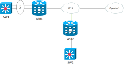
000080: Jan 20 12:21:54 MSK: %PM-4-ERR_DISABLE: channel-misconfig (STP) error detected on Gi1/0/26, putting Gi1/0/26 in err-disable state
000081: Jan 20 12:21:55 MSK: %PM-4-ERR_DISABLE: channel-misconfig (STP) error detected on Gi1/0/27, putting Gi1/0/27 in err-disable state
000082: Jan 20 12:21:55 MSK: %PM-4-ERR_DISABLE: channel-misconfig (STP) error detected on Gi1/0/28, putting Gi1/0/28 in err-disable state
000083: Jan 20 12:21:55 MSK: %PM-4-ERR_DISABLE: channel-misconfig (STP) error detected on Po1, putting Gi1/0/21 in err-disable state
000084: Jan 20 12:21:55 MSK: %PM-4-ERR_DISABLE: channel-misconfig (STP) error detected on Po1, putting Gi1/0/22 in err-disable state
000085: Jan 20 12:21:55 MSK: %PM-4-ERR_DISABLE: channel-misconfig (STP) error detected on Po1, putting Gi1/0/23 in err-disable state
000086: Jan 20 12:21:55 MSK: %PM-4-ERR_DISABLE: channel-misconfig (STP) error detected on Po1, putting Gi1/0/24 in err-disable state
000087: Jan 20 12:21:55 MSK: %PM-4-ERR_DISABLE: channel-misconfig (STP) error detected on Po1, putting Gi1/0/25 in err-disable state
000088: Jan 20 12:21:55 MSK: %PM-4-ERR_DISABLE: channel-misconfig (STP) error detected on Po1, putting Gi1/0/26 in err-disable state
000089: Jan 20 12:21:55 MSK: %PM-4-ERR_DISABLE: channel-misconfig (STP) error detected on Po1, putting Gi1/0/27 in err-disable state
000090: Jan 20 12:21:55 MSK: %PM-4-ERR_DISABLE: channel-misconfig (STP) error detected on Po1, putting Gi1/0/28 in err-disable state
000091: Jan 20 12:21:55 MSK: %PM-4-ERR_DISABLE: channel-misconfig (STP) error detected on Po1, putting Po1 in err-disable state
Возможно совпадение, но несколько недель назад мы подключили к данному VPLS еще и Operator1 (клиент, которому отдаем мультикаст). Есть подозрение, что он иногда присылает какой-то кривой BPDU и из за этого все падает. Просто заметил, что root-bridge для коммутатора SW1 была какая-то железка, которая явно не моя. Судя по OUI префиксу какой-то джунипер (у меня их нет). Сейчас я поменял root уже на свой коммутатор. Так же на коммутаторе SW1 включил «errdisable recovery cause channel-misconfig». Можно как-то на ASR отфильтровать все BDPU от Operator1? По аналогии со spanning-tree bpdufilter на коммутаторах? И можно повесить spanning-tree bpdufilter на интерфейсы коммутаторов, которыми они к VPLS подключены? Сейчас один из них является root-bridge
Изменено 21 января, 2022 пользователем fox_m
Recently I was trying to bring up a EtherChannel connection between a Catalyst 3750 and a Catalyst 4507.
I was going to join 4 ports together. One from each of the first 4 blades on the 4507. It is good to use several blades to protect against a blade failure.
However, when I went to bring up the bundle using LACP, within seconds all bundled ports were shut down and this logging message popped up:
%PM-4-ERR_DISABLE: channel-misconfig (STP) error detect on GigabitEthernet1/0/45.
I was really stumped as to what was causing this. Google searching did not really return any clear answers.
The message was stating that there error was somehow related to Spanning Tree Protocol. I turned on all Spanning Tree debugs and re-enabled just the first port again, but the debugs didn’t show anything unusual happening. What was interesting is that this error was only occurring on the 3750, no errors were showing up on the 4507. I double checked the STP root bridge priorities, etc.
I started to comb the running-config with a fine toothed comb on the 3750. It was then that I noticed this config towards the top:
spanning-tree etherchannel guard misconfig
This config intrigued me. I had not noticed it before and I was unclear as to what it might do. I no’d out the command and again tried to bring up just the first interface in the bundle. No cigar, same epic fail. At this point, I saved the config (write me) and reloaded the switch. Once the switch was back up, I again tried to bring the the bundle members, but in reverse order, starting with gi1/0/48 and moving towards gi1/0/45. One by one, they were each able to join the bundle. Finally, I went to bring up the last interface, gi1/0/45. It came up, however the command show etherchannel 2 summary showed that it was in the waiting state. This is indicated by state w. It seemed to stay in waiting for about a minute until it changed to I. The status I indicates that the port is individual and not part of the bundle.
I thought that it was strange for gi1/0/45 to go to individual mode. I then traced the cabling from gi1/0/45 on the 3750 to fa3/3 on the 4507. “Now just you wait a sec!” I found that I had accidentally cabled to port fa3/5 instead. This was the wrong port and was not configured to be part of the etherchannel.
Wow, so
spanning-tree etherchannel guard misconfig
Was trying to tell me that I had a mis-cabled port! That’s pretty sweet. I did a quick google search on the command and found that essentially it allows EtherChannel to use STP to attempt to find misconfigurations (including messed up cabling).
http://www.cisco.com/en/US/docs/switches/lan/catalyst6500/ios/12.2SXF/native/configuration/guide/stp_enha.html#wp1029499
This story has two morals:
1) Definitely configure STP etherchannel guard misconfig. That command is just another of those that will watch your back. You just gotta love those commands.
2) If your ports are going err-diable and your getting that odd STP misconfig error. Remember to go check your cabling and which ports are config’d.
Happy Routing!
Switch Port Aggregation with EtherChannel – LACP, PAgP and ON (manual)
EtherChannel provides fault-tolerant high-speed links between switches, routers, and servers. You can use it to increase the bandwidth between the wiring closets and the data center, and you can deploy it anywhere in the network where bottlenecks are likely to occur. EtherChannel provides automatic recovery for the loss of a link by redistributing the load across the remaining links. If a link fails, EtherChannel redirects traffic from the failed link to the remaining links in the channel without intervention.
Two to eight links of either FastEthernet (FE), Gigabit Ethernet (GE), or 10-Gigabit Ethernet (10GE) can be bundled as one logical link of Fast EtherChannel (FEC), Gigabit EtherChannel (GEC), or 10-GigabitEtherchannel (10GEC), respectively. This bundle provides a full-duplex bandwidth of up to 1600 Mbps (eight links of Fast Ethernet), 16 Gbps (eight links of GE), or 160 Gbps (eight links of 10GE).
This also provides an easy means to expand a link’s capacity between two switches, without having to continually purchase hardware for the next magnitude of throughput. A single FastEthernet link (200 Mbps throughput) can be incrementally expanded up to eight Fast Ethernet links (1600 Mbps) as a single FastEtherChannel. If the traffic load grows beyond that, the growth process can begin again with a single GE link (2 Gbps throughput), which can be expanded up to eight GE links as a Gigabit EtherChannel (16 Gbps). The process repeats again by moving to a single 10GE link, and so on.
Having multiple or parallel links between switches creates the possibility of bridging loops, running STP. EtherChannel avoids this situation by bundling parallel links into a single, logical link, which can act as either an access or a trunk link. Although an EtherChannel link is seen as a single logical link, the link does not necessarily have an inherent total bandwidth equal to the sum of its component physical links.
For example, a GEC link is made up of four full-duplex 1-Gbps GE links. Although it is possible for the GEC link to carry a total throughput of 8 Gbps (if each link becomes fully loaded), the single resulting GEC bundle does not operate at this speed.
Instead, traffic is distributed across the individual links within the EtherChannel. Each of these links operates at its inherent speed (2 Gbps full duplex for GE) but carries only the frames placed on it by the EtherChannel hardware. If the load-distribution algorithm favors one link within the bundle, that link will carry a disproportionate amount of traffic. In other words, the load is not always distributed equally among the individual links.
EtherChannel also provides redundancy with several bundled physical links. If one of the links within the bundle fails, traffic sent through that link is automatically moved to an adjacent link. Failover occurs in less than a few milliseconds and is transparent to the end user. As more links fail, more traffic is moved to further adjacent links. Likewise, as links are restored, the load automatically is redistributed among the active links.
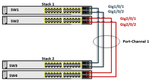
When planning an EtherChannel, you should give some thought to different failure scenarios. The failure of a single physical link within an EtherChannel is not catastrophic because the switches compensate by moving traffic to the other, still functioning, links. However, what if all of the physical links are connected to the same switch? The switch itself might fail someday, taking all of the physical links of the EtherChannel down with it.
A better solution involves distributing the physical links across multiple switches at each end of the EtherChannel. This is possible when the switches are configured as one logical or virtual switch, such as the Cisco stackable Catalyst switches or chassisbased Virtual Switching System (VSS) switch families. In the next figure, a four-port GEC is made up of two links connected to the first switch in a stack and two links connected to the second switch in a stack. This is known as a Multichassis EtherChannel (MEC). Even if one switch fails within a stack, the MEC will keep functioning thanks to the other stacked switch. Bellow a picture of an EtherChannel on a Chassis based Virtual Switching System (VSS).
Usually, all bundled ports first must belong to the same VLAN. If used as a trunk, bundled ports must be in trunking mode, have the same native VLAN, and pass the same set of VLANs. Each of the ports should have the same speed and duplex settings before being bundled. Bundled ports also must be configured with identical spanning-tree settings.
Port-Channel Interfaces
When you create an EtherChannel, a port-channel logical interface guideline is the following:
- With Layer 2 ports, use the channel-group interface configuration command to dynamically create the port-channel logical interface. You also can use the interface port-channel port-channel-number command to manually create the port-channel logical interface, but then you must use the channel-group channel-group-number command to bind the logical interface to a physical port. The channel-group-number can be the same as the port-channel-number, or you can use a new number. If you use a new number, the channel-group command dynamically creates a new port channel.
- With Layer 3 ports, you should manually create the logical interface by using the interface port-channel command followed by the no switchport command. Then you manually assign an interface to the EtherChannel by using the channel-group command.
For both Layer 2 and Layer 3 ports, the channel-group command binds the physical port and the logical interface together. Each EtherChannel has a port-channel logical interface numbered from 1 to 48. This port-channel interface number corresponds to the one specified with the channel-group command.
Note: After configuring an EtherChannel, configuration changes done to the port-channel interface apply to all the physical ports assigned to the port-channel interface. Configuration changes done to one physical port affect only the port where you apply the configuration. To change the parameters of all ports in an EtherChannel, apply configuration to the port-channel interface.
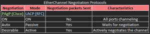
EtherChannel Negotiation Protocols
EtherChannels can be negotiated between two switches to provide some dynamic link configuration. Two protocols are available in Catalyst switches. Port Aggregation Protocol (PAgP) is a Cisco proprietary solution, and the Link Aggregation Control Protocol (LACP) is standards based. The following table shows the protocols and their negotiation characteristics.
Default EtherChannel Configuration

EtherChannel Configuration Guidelines
If improperly configured, some EtherChannel ports are automatically disabled to avoid network loops and other problems. Follow these guidelines to avoid configuration problems:
- Do not try to configure more than 48 EtherChannels on the switch.
- Configure a PAgP EtherChannel with up to eight Ethernet ports of the same type.
- Configure a LACP EtherChannel with up to16 Ethernet ports of the same type. Up to eight ports can be active, and up to eight ports can be in standby mode.
- Configure all ports in an EtherChannel to operate at the same speeds and duplex modes.
- Enable all ports in an EtherChannel. A port in an EtherChannel that is disabled by using the shutdown interface configuration command is treated as a link failure, and its traffic is transferred to one of the remaining ports in the EtherChannel.
- When a group is first created, all ports follow the parameters set for the first port to be added to the group. If you change the configuration of one of these parameters, you must also make the changes to all ports in the group:
–Allowed-VLAN list
–Spanning-tree path cost for each VLAN
–Spanning-tree port priority for each VLAN
–Spanning-tree Port Fast setting
- Do not configure a port to be a member of more than one EtherChannel group.
- Do not configure an EtherChannel in both the PAgP and LACP modes. EtherChannel groups running PAgP and LACP can coexist on the same switch. Individual EtherChannel groups can run either PAgP or LACP, but they cannot interoperate.
- Do not configure a Switched Port Analyzer (SPAN) destination port as part of an EtherChannel.
- Do not configure a secure port as part of an EtherChannel or the reverse.
- Do not configure a private-VLAN port as part of an EtherChannel.
Port Aggregation Protocol
PAgP packets are exchanged between switches over EtherChannel-capable ports. Neighbors are identified and port group capabilities are learned and compared with local switch capabilities. Ports that have the same neighbor device ID and port group capability are bundled together as a bidirectional, point-to-point EtherChannel link. PAgP forms an EtherChannel only on ports that are configured for either identical static VLANs or trunking.
PAgP also dynamically modifies parameters of the EtherChannel if one of the bundled ports is modified. If the configured VLAN, speed, or duplex mode of a port in an established bundle is changed, PAgP reconfigures that parameter for all ports in the bundle. PAgP can be configured in desirable, in which it actively asks a farend switch to negotiate an EtherChannel, or in auto, (default), in which it negotiates an EtherChannel only if the far end initiates it.
PAgP Negotiation Modes

Note: Switch ports exchange PAgP packets only with partner ports configured in the auto or desirable modes. Ports configured in the on mode do not exchange PAgP packets.
Ports can form an EtherChannel when they are in different PAgP modes as long as the modes are compatible.:
- Desirable can form an EtherChannel with another port that is in the desirable or auto mode.
- Auto can form an EtherChannel with another port in the desirable mode.
Note: Auto cannot form an EtherChannel with another port that is also in the auto mode because neither port starts PAgP negotiation.
Configure two ports as static-access ports in VLAN 10 to channel 5 with the PAgP mode desirable:
Switch# configure terminal
Switch(config)# interface range gigabitethernet0/1 - 2
Switch(config-if-range)# switchport mode access
Switch(config-if-range)# switchport access vlan 10
Switch(config-if-range)# channel-protocol pagp
Switch(config-if-range)# channel-group 5 mode desirable non-silent
Switch(config-if-range)# end
Configure two ports as trunk ports to channel 1 with the PAgP mode desirable:
Switch# configure terminal
Switch(config)# interface range gigabitethernet0/4 - 6
Switch(config-if-range)# switchport trunk encapsulation dot1q
Switch(config-if-range)# switchport mode trunk
Switch(config-if-range)# channel-protocol pagp
Switch(config-if-range)# channel-group 1 mode desirable non-silent
Switch(config-if-range)# end
Silent Command Option
non-silent – (Optional) If your switch is connected to a partner that is PAgP-capable, configure the switch port for nonsilent operation when the port is in auto or desirable mode. If you do not specify non-silent, silent is assumed.
silent – for connections to file servers or packet analyzers that are not generating traffic. This setting allows PAgP to operate, to attach the port to a channel group, and to use the port for transmission.
In this case, running PAgP on a physical port connected to a silent partner prevents that switch port from ever becoming operational. However, the silent setting allows PAgP to operate, to attach the port to a channel group, and to use the port for transmission.
PAgP Learn Method and Priority
Network devices are classified as PAgP Physical or Aggregate-port learners.
A device is a physical learner if it learns addresses by physical ports and directs transmissions based on that knowledge.
A device is an aggregate-port learner if it learns addresses by aggregate (logical) ports. The learn method must be configured the same at both ends of the link.
When a device and its partner are both aggregate-port learners, they learn the address on the logical port-channel. The device sends packets to the source by using any of the ports in the EtherChannel. With aggregate-port learning, it is not important on which physical port the packet arrives.
PAgP cannot automatically detect when the partner device is a physical learner and when the local device is an aggregate-port learner. You must manually set the learning method on the local device to learn addresses by physical ports.
Note: You also must set the load-distribution method to source-based distribution, so that any given source MAC address is always sent on the same physical port.
Configure PAgP learning method.
By default, aggregation-port learning is selected, which means the switch sends packets to the source by using any of the ports in the EtherChannel.
With aggregate-port learning, it is not important on which physical port the packet arrives.
Select physical-port to connect with another switch that is a physical learner. Make sure to configure the port-channel load-balance command to src-mac. The learning method must be configured the same at both ends of the link.
SW1# conf t
Enter configuration commands, one per line. End with CNTL/Z.
SW1(config)# int e0/0
SW1(config-if)# pagp learn-method ?
 aggregation-port   Learns the destination on the agport
 physical-port      Learns the destination on the physical port
SW1(config-if)# pagp learn-method
Configure PAgP Port Priority.
You also can configure a single port within the group for all transmissions and use other ports for hot standby. The unused ports in the group can be swapped into operation in just a few seconds if the selected single port loses hardware-signal detection.
You can configure which port is always selected for packet transmission by changing its priority with the pagp port-priority interface command. The higher the priority, the more likely that the port will be selected.
Manually assign a priority so that the selected port is chosen for packet transmission. For priority, the range is 0 to 255. The default is 128. The higher the priority, the more likely that the port will be used for PAgP transmission.
SW1# conf t
Enter configuration commands, one per line. End with CNTL/Z.
SW1(config)# interface e0/0
SW1(config-if)# pagp port-priority 150
SW1(config-if)# end
SW1#
*Dec 7 13:05:43.658: %SYS-5-CONFIG_I: Configured from console by console
SW1# show pagp 1 internal
Flags: S - Device is sending Slow hello. C - Device is in Consistent state.
 A - Device is in Auto mode. d - PAgP is down
Timers: H - Hello timer is running. Q - Quit timer is running.
 S - Switching timer is running. I - Interface timer is running.

Channel group 1
 Hello Partner PAgP Learning Group
Port Flags State  Timers  Interval Count Priority Method Ifindex
Et0/0 SC   U6/S7   H      30s       1     150      Any    18
Et0/1 SC   U6/S7   H      30s       1     128      Any    18
Et0/2 SC   U6/S7   H      30s       1     128      Any    18
Et0/3 SC   U6/S7   H      30s       1     128      Any    18
SW1#
Verify PAgP
Displays EtherChannel information in a brief, detailed, and one-line summary form. Also displays the load-balance or frame-distribution scheme, port, port-channel, and protocol information.
Switch# show etherchannel [channel-group-number {detail | port | port-channel | protocol | summary}] {detail | load-balance | port | port-channel | protocol | summary}
Displays PAgP information such as traffic information, the internal PAgP configuration, and neighbor information.
Switch# show pagp [channel-group-number] {counters | internal |neighbor}
Displays the dual-active detection status.
Switch# show pagp [channel-group-number] dual-active
Clear PAgP channel-group information and traffic counters
Switch# clear pagp {channel-group-number counters | counters}
PAgP Interaction with Other Features
DTP and CDP send and receive packets over the physical ports in the EtherChannel. Trunk ports send and receive PAgP protocol data units (PDUs) on the lowest numbered VLAN.
In Layer 2 EtherChannels, the first port in the channel that comes up provides its MAC address to the EtherChannel. If this port is removed from the bundle, one of the remaining ports in the bundle provides its MAC address to the EtherChannel.
For Layer 3 EtherChannels, the MAC address is allocated by the stack master as soon as the interface is created (through the interface port-channel command). PAgP sends and receives PAgP PDUs only from ports that are up and have PAgP enabled for the auto or desirable mode.
Link Aggregation Control Protocol
LACP is a standards-based defined in IEEE 802.3ad. LACP packets are exchanged between switches over EtherChannel-capable ports. As with PAgP, neighbors are identified and port group capabilities are learned and compared with local switch capabilities. However, LACP also assigns roles to the EtherChannel’s endpoints.
The switch with the lowest system priority (a 2-byte priority value followed by a 6-byte switch MAC address) is allowed to make decisions about what ports actively are participating in the EtherChannel at a given time. Ports are selected and become active according to their port priority value (a 2-byte priority followed by a 2-byte port number), where a low value indicates a higher priority.
A set of up to 16 potential links can be defined for each EtherChannel. Through LACP, a switch selects up to eight of these having the lowest port priorities as active EtherChannel links at any given time. The other links are placed in a standby state and will be enabled in the EtherChannel if one of the active links goes down. Like PAgP, LACP can be configured in active mode (active), in which a switch actively asks a far-end switch to negotiate an EtherChannel, or in passive mode (passive), in which a switch negotiates an EtherChannel only if the far end initiates it.
LACP Negotiation Modes

Active and passive LACP modes enable ports to negotiate with partner ports to an EtherChannel based on port speed and, for Layer 2 EtherChannels, trunking state and VLAN numbers.
Ports can form an EtherChannel when they are in different LACP modes as long as the modes are compatible
- Active mode can form an EtherChannel with another port that is in the active or passive mode.
- Passive mode cannot form an EtherChannel with another port that is also in the passive mode because neither port starts LACP negotiation.
LACP System and Port Priority and Hot-Standby Ports
When enabled, LACP tries to configure the maximum number of LACP-compatible ports in a channel, up to a maximum of 16 ports. Only eight LACP links can be active at one time. It places any additional links in a hot-standby mode. If one of the active links becomes inactive, a link that is in the hot-standby mode becomes active in its place.
If you configure more than eight links for an EtherChannel group, the software automatically decides which of the hot-standby ports to make active based on the LACP priority. To every link between systems that operate LACP, the software assigns a unique priority made up of these elements (in priority order):
- LACP system priority
- System ID (the switch MAC address)
- LACP port priority
- Port number
Numerically lower values have higher priority. The priority decides which ports should be put in standby mode when there is a hardware limitation that prevents all compatible ports from aggregating.
Determining which ports are active and which are hot standby is a two-step procedure. First the system with a numerically lower system priority and system-id is placed in charge of the decision. Next, that system decides which ports are active and which are hot standby, based on its values for port priority and port number. The port-priority and port-number values for the other system are not used.
LACP System Priority
- 1 to 65,535
- default 32,768
One switch should be assigned a lower system priority than the other so that it can make decisions about the EtherChannel’s makeup, otherwise both switches will have the same system priority (32,768), and the one with the lower MAC address will become the decision maker.
Each interface included in a single EtherChannel bundle must be assigned to the same unique channel group number (1 to 64).
Note: Channel negotiation must be set to ON , (no LACP negotiation).
You can configure more interfaces in the channel group number than are allowed to be active in the channel. This prepares extra standby interfaces to replace failed active ones.
LACP Port Priority , Active & Standby State
Use the lacp port-priority command to configure a lower port priority, default 32,768 , for any interfaces that must be Active
A higher priority for interfaces that might be held in the Standby state. Priority range from 1 to 65,535 (default 32,768)
Otherwise, just use the default scenario, in which all ports default to 32,768 and the lower port numbers (in interface number order) are used to select the active ports.
Suppose that you want to configure a switch to negotiate a Gigabit EtherChannel using interfaces Gigabit Ethernet 1/0/1 – 1/0/4 and 2/0/1 – 2/0/4.
Interfaces Gigabit Ethernet 1/0/5 – 1/0/8 and 2/0/5 – 2/0/8 are also available, so they can be used as Standby links to replace failed links in the channel. This switch should actively negotiate the channel and should be the decision maker about the channel operation.
SW1(config)# lacp system-priority 100
SW1(config)# interface range gig 1/0/1 – 4 , gig 2/0/1 – 4
SW1(config-if)# channel-protocol lacp
SW1(config-if)# channel-group 1 mode active
SW1(config-if)# lacp port-priority 100
SW1(config-if)# exit
SW1(config)# interface range gig 1/0/5 – 8 , gig 2/0/5 – 8
SW1(config-if)# channel-protocol lacp
SW1(config-if)# channel-group 1 mode active
Note: Notice that interfaces gig 1/0/5-8 and 2/0/5-8 have been left to their default port priorities of 32,768. This is higher than the others, which were configured for 100, so they will be held as standby interfaces.
Verify LACP
Displays LACP information such as traffic information, the internal LACP configuration, and neighbor information.
Switch# show lacp [channel-group-number] {counters | internal |neighbor}
LACP Interaction with Other Features
DTP and CDP send and receive packets over the physical ports in the EtherChannel. Trunk ports send and receive LACP PDUs on the lowest numbered VLAN.
In Layer 2 EtherChannels, the first port in the channel that comes up provides its MAC address to the EtherChannel. If this port is removed from the bundle, one of the remaining ports in the bundle provides its MAC address to the EtherChannel. For Layer 3 EtherChannels, the MAC address is allocated by the stack master as soon as the interface is created through the interface port-channel global configuration command.
LACP sends and receives LACP PDUs only from ports that are up and have LACP enabled for the active or passive mode.
EtherChannel On Mode
ON mode is used to manually configure an EtherChannel. The ON mode forces a port to join an EtherChannel without negotiations. It can be useful if the remote device does not support PAgP or LACP. In ON mode, a usable EtherChannel exists only when the switches at both ends of the link are configured in ON mode.
Ports that are configured in the ON mode in the same channel group must have compatible port characteristics, speed and duplex. Ports that are not compatible are suspended, even though they are configured in ON mode.
Note: Ports on both ends of the EtherChannel must have the same configuration. If the group is misconfigured, packet loss or spanning-tree loops can occur.
Configure four ports to bundle in channel 1 with mode ON
SW1(config)# interface range gig 0/0/0 – 4
SW1(config-if)# switchport
SW1(config-if)# switchport nonegotiate
SW1(config-if)# switchport trunk encapsulation dot1q
SW1(config-if)# switchport mode trunk
SW1(config-if)# channel-group 1 mode on
SW1(config-if)# no shut
Distributing Traffic in EtherChannel
Traffic in an EtherChannel is distributed across the individual bundled links in a deterministic fashion but the load is not necessarily balanced equally across all the links.
Instead, frames are forwarded on a specific link as a result of a hashing algorithm. The algorithm can use source IP, destination IP, or a combination of source and destination IP, source and destination MAC, or TCP/UDP port numbers. The hash algorithm computes a binary pattern that selects a link number in the bundle to carry each frame.
If only one address or port number is hashed, a switch forwards each frame by using one or more low-order bits of the hash value as an index into the bundled links.
If two addresses or port numbers are hashed, a switch performs an exclusive-OR (XOR) operation on one or more low-order bits of the addresses or TCP/UDP port numbers as an index into the bundled links.
An EtherChannel consisting of two links bundled together requires a 1-bit index. If the index is 0, link 0 is selected; if the index is 1, link 1 is used.
Either the lowest-order address bit or the XOR of the last bit of the addresses in the frame is used as the index. A four-link bundle uses a hash of the last 2 bits. Likewise, an eight-link bundle uses a hash of the last 3 bits. The hashing operation’s outcome selects the EtherChannel’s outbound link.
Bellow shows the results of an XOR on a two-link bundle, using the source and destination addresses.

On most of the CISCO switches platform, default ether-channel load-balance algorithm is “XOR source and destination IP ” to do the load-balance. The load-balancing is purely based on hashing provided by the hardware, which is in turn based on flows. You can essentially end up with a load balance setup that never changes links depending on your configured flows.
You can choose whether to hash on 3 Layers (L2, L3, L4) with Src or Dst MAC, IP Address, or Ports flow information, but hash algorithm cannot be configured or changed to load balance the traffic among the ports in an Etherchannel.
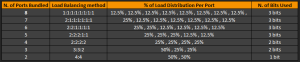
To understand at a low level view, Cisco’s proprietary hash algorithm computes a value in the range 0 to 7. With this value as a basis, a particular port in the EtherChannel is chosen. The port setup includes a mask which indicates which values the port accepts for transmission.
With the maximum number of ports in a single EtherChannel, (8 ports), each port accepts only one value. If you have four ports in the EtherChannel, each port accepts two values, and so forth. Bellow is the ratios of the values that each port accepts, which depends on the number of ports in the EtherChannel:
XOR Operation is performed independently on each bit position in the address value. If the two address values have the same bit value, the XOR result is always 0. If the two address bits differ, the XOR result is always 1.
1 0 = 0
1 1 = 1
In this way, frames can be distributed statistically among the links with the assumption that MAC or IP addresses themselves are distributed statistically throughout the network.
In a four-link EtherChannel, the XOR is performed on the lower 2 bits of the address values, resulting in a 2-bit XOR value (each bit is computed separately) or a link number from 0 to 3.
Consider a packet being sent from IP address 192.168.1.1 to 172.31.67.46. Because EtherChannels can be built from two to eight individual links, only the rightmost (least-significant) 3 bits are needed as a link index.
From the source and destination addresses, these bits are 001 (1) and 110 (6), respectively. For a two-link EtherChannel, a 1-bit XOR is performed on the rightmost address bit:
xxxxxxxx.xxxxxxxx.xxxxxxxx.xxxxx|xx1
1 XOR 0 = 1, causing Link 1 in the bundle to be used. 10 = 1
A four-link EtherChannel produces a 2-bit XOR:
01 XOR 10 = 11, causing Link 3 in the bundle to be used, 11 = 2+1=3
Finally, an eight-link EtherChannel requires a 3-bit XOR:
001 XOR 110 = 111, where Link 7 in the bundle is selected, 111 = 4+2+1=7
MAC Address Based Forwarding
With source-MAC, when packets are forwarded, they are distributed across the ports in the channel based on the incoming packet. Therefore, to provide load-balancing, packets from different hosts use different ports in the channel, but packets from the same host use the same port in the channel.
With destination-MAC, when packets are forwarded, they are distributed across the ports in the channel based on the destination host’s MAC address of the incoming packet. Therefore, packets to the same destination are forwarded over the same port, and packets to a different destination are sent on a different port in the channel.
With source-and-destination MAC, when packets are forwarded, they are distributed across the ports in the channel based on both the source and destination. This forwarding method, a combination source-MAC and destination-MAC address methods of load distribution, can be used if it is not clear whether source-MAC or destination-MAC address is better suited on a particular switch. With source-and-destination MAC, packets sent from host A to host B, host A to host C, and host C to host B could all use different ports in the channel.
IP Address Based Forwarding
With source-IP, when packets are forwarded, they are distributed across the ports based on the source-IP of the incoming packet. Therefore, to provide load-balancing, packets from different IPs use different ports in the channel, but packets from the same IP address use the same port in the channel.
With destination-IP, when packets are forwarded, they are distributed across the ports based on the destination-IP of the incoming packet. Therefore, to provide load-balancing, packets from the same IP source address sent to different IP destination addresses could be sent on different ports in the channel. But packets sent from different source IP addresses to the same destination IP address are always sent on the same port in the channel.
With source-and-destination IP, when packets are forwarded, they are distributed across the ports based on both the source and destination IP of the incoming packet. This combination of source-IP and destination-IP address-based forwarding, can be used if it is not clear whether source-IP or destination-IP based forwarding is better suited on a particular switch. Packets sent from the IP address A to IP address B, from IP address A to IP address C, and from IP address C to IP address B could all use different ports in the channel.
Different load-balancing methods have different advantages, and the choice of a particular load-balancing method should be based on the position of the switch in the network and the kind of traffic that needs to be load-distributed. An EtherChannel of four workstations communicates with a router.
Because the router is a single-MAC-address device, source-based forwarding on the switch EtherChannel ensures that the switch uses all available bandwidth to the router. The router is configured for destination-based forwarding because the large number of workstations ensures that the traffic is evenly distributed from the router EtherChannel. Bellow are the types of load-balancing methods.

Frame distribution for all EtherChannel switch links src-dst-mac (XOR) based forwarding:
Switch(config)# port-channel load-balance src-dst-mac
Verify Load Balancing Method
Switch# show etherchannel load-balance
EtherChannel    Load-Balancing    Configuration:
                 src-dst-mac

EtherChannel  Load-Balancing Addresses Used Per-Protocol:
Non-IP:    Source XOR Destination MAC address
IPv4:      Source XOR Destination MAC address
IPv6:      Source XOR Destination MAC address
Switch#

SW1# show etherchannel port-channel
 Channel-group listing:
 ----------------------

Group: 1
----------
 Port-channels in the group:
---------------------------
Port-channel: Po1  (Primary Aggregator)
------------

Age of the Port-channel = 0d:01h:00m:37s
Logical slot/port = 16/0 Number of ports = 4
GC = 0x00010001 HotStandBy port = null
Port state = Port-channel Ag-Inuse
Protocol = LACP
Port security = Disabled

Ports in the Port-channel:

Index   Load   Port      EC state       No of bits
------+------+------+------------------+-----------
 0       00    Et0/0   Active              0
 0       00    Et0/1   Active              0
 0       00    Et0/2   Passive             0
 0       00    Et0/3   Passive             0

Time since last port bundled: 0d:00h:33m:47s Et0/0
Time since last port Un-bundled: 0d:00h:33m:49s Et0/0
SW1#
Configuring Layer 3 EtherChannels
To configure Layer 3 EtherChannels, you first create the port-channel logical interface and then put the Ethernet ports into the port-channel as described next.
Creating Port-Channel Logical Interfaces
When configuring Layer 3 EtherChannels, you should first manually create the port-channel logical interface by using the interface port-channel command. Then you put the logical interface into the channel group by using the channel-group command.
Note: To move an IP address from a physical port to an EtherChannel, you must delete the IP address from the physical port before configuring it on the port-channel interface.
Configure the logical port channel 5 and assign 172.10.20.10 as its IP address:
Switch# configure terminal
Switch(config)# interface port-channel 5
Switch(config-if)# no switchport
Switch(config-if)# ip address 172.10.20.10 255.255.255.0
Switch(config-if)# end
Configuring the Physical Interfaces
Assigns two ports to channel 5 with the LACP mode active
Switch# configure terminal
Switch(config)# interface range gigabitethernet0/1 -2
Switch(config-if-range)# no ip address
Switch(config-if-range)# no switchport
Switch(config-if-range)# channel-group 5 mode active
Switch(config-if-range)# end
Assigns two ports to channel 1 with the PAgP mode desirable
Switch# configure terminal
Switch(config)# interface range gigabitethernet0/0 -1
Switch(config-if-range)# no ip address
Switch(config-if-range)# no switchport
Switch(config-if-range)# channel-protocol pagp (optional since 'desirable' defines pagp as the protocol)
Switch(config-if-range)# channel-group 1 mode desirable
Switch(config-if-range)# end
Preventing Misconfiguration with EtherChannel Guard
Once you configure a set of physical interfaces on one switch to participate in an EtherChannel, you should configure the corresponding interfaces on the neighboring switch. Your goal should be to keep the EtherChannel configurations as predictable as possible, so that nothing unexpected can happen.
Suppose that you configure two interfaces on Switch A to form an unconditional EtherChannel that carries all active VLANs. Your associate configures Switch B for the same set of two interfaces, but manages to plug the cables into the wrong two interfaces. It is entirely possible that a bridging loop might form over the dual links because an EtherChannel has not formed on both ends.
STP will not operate consistently on all interfaces because Switch A is expecting a working EtherChannel. If you decide to use PAgP or LACP to negotiate an EtherChannel, the chances of a misconfiguration are slim. An EtherChannel will not be built if it cannot be negotiated on all member links on the switches at both ends.
To reduce the chances of a misconfigured EtherChannel, Cisco switches run the EtherChannel Guard feature by default.
You can control the feature with the following command (to enble, or negate it to disable):
Switch(config)# [no] spanning-tree etherchannel guard misconfig
If a misconfiguration is detected once the interfaces are enabled, the switch will log the problem and will automatically shut the interfaces down and place them in the errdisable state.
two interfaces should have formed an EtherChannel, but a misconfiguration has been detected. Notice that both member interfaces, as well as the port channel 1 EtherChannel interface, have been errdisabled. To see the reason behind this action, use the show interfaces status err-disabled command.
Dec 8 05:02:16.073: %PM-4-ERR_DISABLE: channel-misconfig (STP) error detected on
Gi1/0/25, putting Gi1/0/25 in err-disable state
Dec 8 05:02:16.081: %PM-4-ERR_DISABLE: channel-misconfig (STP) error detected on
Gi1/0/26, putting Gi1/0/26 in err-disable state
Dec 8 05:02:16.115: %PM-4-ERR_DISABLE: channel-misconfig (STP) error detected on
Po1, putting Gi1/0/25 in err-disable state
Dec 8 05:02:16.115: %PM-4-ERR_DISABLE: channel-misconfig (STP) error detected on
Po1, putting Gi1/0/26 in err-disable stning-ate
Dec 8 05:02:16.115: %PM-4-ERR_DISABLE: channel-misconfig (STP) error detected on
Po1, putting Po1 in err-disable state
Dec 8 05:02:17.079: %LINEPROTO-5-UPDOWN: Line protocol on Interface GigabitEthernet1/0/25, changed state to down
Dec 8 05:02:17.096: %LINEPROTO-5-UPDOWN: Line protocol on Interface GigabitEthernet1/0/26, changed state to down
Dec 8 05:02:17.104: %LINEPROTO-5-UPDOWN: Line protocol on Interface Port-channel1,
changed state to down
Switch# show interface status err-disabled
Port Name Status Reason Err-disabled Vlans
Gi1/0/25 err-disabled channel-misconfig (STP)
Gi1/0/26 err-disabled channel-misconfig (STP)
Po1 err-disabled channel-misconfig (STP)
Switch#
To recover from a misconfigured EtherChannel, first review the interface configuration on both switches.
After you have corrected the problem, you must shut down the port channel interface and reenable it. The member interfaces will follow suit automatically.
Reenabling a Misconfigured EtherChannel
 Switch(config)# interface port-channel1
Switch(config-if)# shutdown
Switch(config-if)# no shutdown
Switch(config-if)# end
Switch#
Mar 30 05:09:21.518: %SYS-5-CONFIG_I: Configured from console by console
Mar 30 05:09:21.719: %LINK-3-UPDOWN: Interface GigabitEthernet1/0/25, changed state to up
Mar 30 05:09:21.736: %LINK-3-UPDOWN: Interface GigabitEthernet1/0/26, changed state to up
Mar 30 05:09:25.536: %LINEPROTO-5-UPDOWN: Line protocol on Interface GigabitEthernet1/0/25, changed state to up
Mar 30 05:09:25.544: %LINEPROTO-5-UPDOWN: Line protocol on Interface GigabitEthernet1/0/26, changed state to up
Mar 30 05:09:26.509: %LINK-3-UPDOWN: Interface Port-channel1, changed state to up
Mar 30 05:09:27.516: %LINEPROTO-5-UPDOWN: Line protocol on Interface Port-channel1, changed state to up
Switch#
Troubleshooting an EtherChannel
If you find that an EtherChannel is having problems, remember that the whole concept is based on consistent configurations on both ends of the channel.
Here are some reminders about EtherChannel operation and interaction:
EtherChannel on mode does not send or receive PAgP or LACP packets. Therefore, both ends should be set to on mode before the channel can form.
- EtherChannel desirable (PAgP) or active (LACP) mode attempts to ask the far end to bring up a channel. Therefore, the other end must be set to either desirable or auto mode.
- EtherChannel auto (PAgP) or passive (LACP) mode participates in the channel protocol, but only if the far end asks for participation. Therefore, two switches in the auto or passive mode will not form an EtherChannel.
- PAgP desirable and auto modes default to the silent submode, in which no PAgP packets are expected from the far end. If ports are set to non-silent submode, PAgP packets must be received before a channel will form.
First verify the EtherChannel state with the show etherchannel summary command. Each port in the channel is shown, along with flags indicating the port’s state, as shown bellow.
Switch# show etherchannel summary
Flags: D - down P - in port-channel
I - stand-alone s - suspended
H - Hot-standby (LACP only)
R - Layer3 S - Layer2
u - unsuitable for bundling
U - in use f - failed to allocate aggregator
d - default port
Number of channel-groups in use:  1
Number of aggregators:            1

 Group Port-channel Protocol     Ports
------+--------------+-----------+------------------------------------------------
1               Po1(SU)       LACP       Gi1/0/1(P) Gi1/0/2(P) Gi1/0/3(D) Gi1/0/4(P)
                                         Gi2/0/1(P) Gi2/0/2(P) Gi2/0/3(P) Gi2/0/4(P)
The status of the port channel shows the EtherChannel logical interface as a whole. This should show SU (Layer 2 channel, in use) if the channel is operational. You also can examine the status of each port within the channel. Notice that most of the channel ports have flags (P), indicating that they are active in the port-channel. One port shows (D) because it is physically not connected or down.
If a port is connected but not bundled in the channel, it will have an independent, or (I), flag. You can verify the channel negotiation mode with the show etherchannel port command.
The local switch interface Gigabit Ethernet 1/0/25 is shown using LACP active mode. Notice that you also verify each end’s negotiation mode under the Flags heading—the local switch as A (active mode) and the partner, or far end switch, as P (passive mode).
Switch# show etherchannel port
Channel-group listing:
----------------------
Group: 1
----------
Ports in the group:
-------------------
Port: Gi1/0/25
------------
Port state     = Up Mstr Assoc In-Bndl
Channel group  = 1 Mode = Active           Gcchange = -
Port-channel   = Po1 GC = -                Pseudo port-channel = Po1
Port index     = 0 Load = 0x00             Protocol = LACP

Flags: S - Device is sending Slow LACPDUs   F - Device is sending fast LACPDUs.
       A - Device is in active mode.        P - Device is in passive mode.

Local information:

                          LACP port        Admin        Oper        Port        Port
Port     Flags   State    Priority          Key         Key         Number      State
Gi1/0/25  SA      bndl    32768             0x1         0x1         0x11A       0x3D

Partner's information:

                   LACP port                         Admin        Oper       Port    Port
Port       Flags   Priority    Dev ID          Age   key          Key        Number  State
Gi1/0/25   SP      32768      aca0.164e.8280   21s   0x0          0x1        0x21A   0x3C
Age of the port in the current state: 0d:00h:02m:37s
---Output Omitted---
Note: Within a switch, an EtherChannel cannot form unless each of the component or member ports is configured consistently. Each must have the same switch mode (access or trunk), native VLAN, trunked VLANs, port speed, port duplex mode, and so on.
Verify a port’s configuration by looking at the
SW# show running-config interface gig0/0/0
SW# show interface gig0/0/0 etherchannel
If you configure a port inconsistently with others for an EtherChannel, you see error messages from the switch.
Some messages from the switch might look like errors but are part of the normal EtherChannel process. As a new port is configured as a member of an existing EtherChannel, you might see this message:
 4d00h: %EC-5-L3DONTBNDL2: GigabitEthernet1/0/11 suspended:
incompatible partner port with GigabitEthernet1/0/10
When the port is first added to the EtherChannel, it is incompatible because the STP runs on the channel and the new port. After STP takes the new port through its states, the port is automatically added into the EtherChannel.
Other messages do indicate a port-compatibility or error. In these cases, the cause of the error is shown. The following message announces that Gigabit Ethernet1/0/3 has a different duplex mode than the other ports in the EtherChannel:
 4d00h: %EC-5-CANNOT_BUNDLE2: GigabitEthernet1/0/3 is not compatible with
GigabitEthernet1/0/1 and will be suspended (duplex of Gi1/0/3 is full, Gi1/0/1 is half)
Finally, you can verify the EtherChannel hashing algorithm. Remember that the switches on either end of an EtherChannel can have different load-balancing methods. The only drawback to this is that the load balancing will be asymmetric in the two directions across the channel.
SW# show etherchannel load-balance
Challenge labs will come soon once I posted all the course contents. Hope this helps someone else!
-
- Forums
-
- Advancing Life & Work
- Alliances
- Around the Storage Block
- HPE Ezmeral: Uncut
- OEM Solutions
- Servers & Systems: The Right Compute
- Tech Insights
- The Cloud Experience Everywhere
- HPE Blog, Austria, Germany & Switzerland
- Blog HPE, France
- HPE Blog, Italy
- HPE Blog, Japan
- HPE Blog, Latin America
- HPE Blog, Poland
- HPE Blog, Hungary
- HPE Blog, UK, Ireland, Middle East & Africa
- Blogs
- Information
-
Forums
-
Blogs
- Advancing Life & Work
- Alliances
- Around the Storage Block
- HPE Ezmeral: Uncut
- OEM Solutions
- Servers & Systems: The Right Compute
- Tech Insights
- The Cloud Experience Everywhere
- HPE Blog, Austria, Germany & Switzerland
- Blog HPE, France
- HPE Blog, Italy
- HPE Blog, Japan
- HPE Blog, Latin America
- HPE Blog, UK, Ireland, Middle East & Africa
- HPE Blog, Poland
- HPE Blog, Hungary
-
Information
-
English
10 REPLIES 10
-
Previous
-
- 1
- 2
-
Next