 Частотные преобразователи относятся к сложной промышленной электронике достаточно дорогой и в тоже время широко распространенной по всему миру. На сегодняшний день трудно себе даже представить какое-либо производство, на котором бы не работало данное промышленное оборудование.
К сожалению, в процессе эксплуатации выходит из строя даже самое надежное промышленное оборудование. В данной статье мы разберем частотный преобразователь Mitsubishi, точнее коды ошибок частотного преобразователя Mitsubishi 700-ой серии (FR-D720S, FR-D720SC, FR-D720EC, FR-D740S, FR-D740SC, FR-D740EC), с полной расшифровкой. Частотники в наше время нашли широкое применения в абсолютно всех сферах промышленности управляя как мини моторами в оргтехнике, так и гигантскими двигателями в горнодобывающей промышленности.
Для простоты общения со столь сложной электроникой все частотные преобразователи оснащены небольшими дисплеями с помощью которых выводятся информационные сообщения с кодами ошибок, расшифровав которые можно сразу же узнать причину ее возникновения. Если учесть распространенность данной промышленной электроники, то появляется острая нужда в расшифровке кодов ошибок частотных преобразователей.
Данная статья даст вам возможность не совершать ошибок, и в добавок поможет самостоятельно определять и устранять ту или иную причину повлекшую за собой аварийную остановку частотных преобразователей Mitsubishi 700-ой серии.

Описание ошибок частотного преобразователя Mitsubishi
В частотных преобразователях Mitsubishi все серьезные сообщения (коды), связанные с ошибками, отображаются вместе с буквой “E” после которой указывается сама ошибка на дисплее преобразователя.
Остальные виды информационных кодов выводятся на дисплей преобразователя без дополнительных префиксов.
На картинке справа приведены все символы, из которых состоят кода ошибок частотных преобразователей Mitsubishi, а также их значения как цифровые, так и буквенные. А в таблицах ниже приведены все коды ошибок частотного преобразователя Mitsubishi с расшифровкой и способом устранения неисправности.
Коды ошибок частотного преобразователя Mitsubishi
|
Ошибка |
Расшифровка кода ошибки |
Устранение ошибки |
|
E— |
Просмотр сохраненных сообщений об ошибках. |
|
|
HOLD |
Блокировка панели управления. |
|
|
LOCD |
Защищено паролем. |
|
|
Er1 |
Ошибка при передаче параметров. |
|
|
Er2 |
|
|
|
Er3 |
|
|
|
Er4 |
|
|
|
Err. |
Сброс частотного преобразователя. |
|
Предупреждающие коды частотного преобразователя Mitsubishi
|
Ошибка |
Расшифровка кода ошибки |
Устранение ошибки |
|
OL |
Защита двигателя от опрокидывания активирована (в следствии тока перегрузки). |
|
|
oL |
Защита двигателя от опрокидывания активирована (в следствии превышения напряжения на промежуточном контуре). |
|
|
rB |
Перегрузка на тормозном сопротивлении. |
|
|
TH |
Предварительный сигнал тревоги электрической защиты двигателя от перегрева. |
|
|
PS |
Останов частотного преобразователя был произведён через панель управления. |
|
|
MT |
Сообщение о необходимости проведения работ по техобслуживанию. |
|
|
UV |
Превышено максимально допустимое напряжение. |
|
|
SA |
Безопасный останов. |
|
Коды ошибок частотного преобразователя Mitsubishi (серьезные неисправности)
|
Ошибка |
Расшифровка кода ошибки |
Устранение ошибки |
|
Fn |
Вентилятор не исправен. |
|
|
E.OC1 |
Отключение по превышению тока при разгоне. |
|
|
E.OC2 |
Отключение по превышению тока при постоянной скорости вращения. |
|
|
E.OC3 |
Отключение по превышению тока в процессе торможения или останова. |
|
|
E.OV1 |
Превышение напряжения при разгоне. |
|
|
E.OV2 |
Превышение напряжения при постоянной скорости вращения. |
|
|
E.OV3 |
Превышение напряжения в процессе торможения или останова. |
|
|
E.THT |
Защита от перегрузки (частотный преобразователь). |
|
|
E.THM |
Защита электродвигателя от перегрузки (срабатывание электрической тепловой защиты). |
|
|
E.FIN |
Перегрев радиатора. |
|
|
E.ILF* |
Рассогласование входных фаз. |
|
|
E.OLT |
Отключающая защита от опрокидывания двигателя. |
|
|
E. BE |
Неисправность встроенного тормозного транзистора. Неисправность во внутреннем электрическом контуре. |
|
|
E. GF |
Ток перегрузки вследствие замыкания на землю. |
|
|
E. LF |
Ошибка выходной фазы |
|
|
E.OHT |
Срабатывание внешней тепловой защиты двигателя (термоконтакта) |
|
|
E.PTC* |
Срабатывание термистора с ПТК |
|
|
E. PE |
Ошибка запоминающего устройства |
|
|
E.PUE |
Неисправность соединения с панелью управления |
|
|
E.rET |
Превышение допустимого количества попыток перезапуска |
|
|
E. 5 |
Ошибка центрального процессора |
|
|
E.CPU |
||
|
E.CDO* |
Превышение допустимого выходного тока |
|
|
E.IOH* |
Перегрев сопротивления включения |
|
|
E.AIE* |
Неисправный аналоговый вход |
|
|
E.SAF* |
Ошибка в защитном контуре |
|
*Если при применении пульта управления FR-PU04 происходит один из следующих сбоев в работе «E.ILF, E.PTC, E.CDO, E.IOH, E.AIE и E.SAF» на дисплее преобразователя появится сообщение об ошибке «Ошибка 14»
Если возникла какая-либо иная ошибка, не описанная выше, свяжитесь с региональным представителем компании Mitsubishi.
Просмотр и удаление списка кодов (сигналов) ошибок
|
Просмотр списка сигналов ошибок после появления серьезной неисправности |
Удаление списка кодов ошибок ПЧ Mitsubishi |
|
|

|

Сброс ошибок и Ремонт частотников Mitsubishi в сервисном центре
Компания «Кернел» производит ремонт промышленной электроники и оборудования с 2002 года. За это время мы накопили колоссальный опыт в том числе опыт в ремонте частотных преобразователей. ![]() Ремонт подобной промышленной электроники ответственное и сложное занятие, требующие максимальной отдачи, профессионализма и максимально полной материальной базе.
Ремонт подобной промышленной электроники ответственное и сложное занятие, требующие максимальной отдачи, профессионализма и максимально полной материальной базе.
Специалисты нашего сервисного центра уделяют максимальное внимание к качеству исполнения ремонта, программирования и настройке промышленного преобразователя частоты, не зависимо от производителя данного промышленного оборудования. Именно поэтому мы смело даем гарантию на все выполненные работы шесть месяцев.
Ремонт частотного преобразователя Mitsubishi производится исключительно с использованием оригинальных запасных частей, на компонентном уровне с применением высокотехнологичного оборудования, квалифицированным персоналом с инженерным образованием.
Если на вашем производстве появились проблемы с частотным преобразователем, которые вы не можете решить самостоятельно, мы всегда рады вам помочь. Обращайтесь в сервисный центр «Кернел». Специалисты нашей компании в минимальные сроки проведут глубокую диагностику и последующий ремонт частотного преобразователя. Оставьте заказ на ремонт оборудования используя форму на сайте, либо свяжетесь с нашими менеджерами, сделать это очень просто.
Как с нами связаться
У вас остались вопросы, связанные с ремонтом, сбросом ошибок, программированием и настройкой частотных преобразователей? Задайте их нашим менеджерам. Связаться с ними можно несколькими способами:

- Заказав обратный звонок (кнопка в правом нижнем углу сайта)
- Посредством чата (кнопка расположена с левой стороны сайта)
- Позвонив по номеру телефона: +7(8482) 79-78-54; +7(917) 121-53-01
- Написав на электронную почту: 89171215301@mail.ru
Далеко не полный список производителей промышленной электроники и оборудования, ремонтируемой в нашей компании.
13 февраля 2023 г. 08:41

При работе промышленной электроники Mitsubishi в системах вентиляции, теплоснабжения или автоматизированном производственном оборудовании часто возникают неисправности, распознать которые можно считав коды ошибок и произведя расшифровку этих кодов по инструкции на конкретную модель электронного оборудования. Наиболее частое использование в промышленном оборудовании получили следующие частотные преобразователи фирмы Mitsubishi: Mitsubishi FR-D700, Mitsubishi FR-E500, Mitsubishi FR-F700, Mitsubishi FR-A500. В свою очередь серия Mitsubishi FR-D700 включает в себя следующие модели: FR-D720-0.1K, FR-D720-0.2K, FR-D720-0.4K, FR-D720-0.75K, FR-D720-1.5K, FR-D720-2.2K, FR-D720-3.7K, FR-D720-5.5K, FR-D720-7.5K, FR-D720-11K, FR-D720-15K, FR-D740-0.4K, FR-D740-0.75K, FR-D740-1.5K, FR-D740-2.2K, FR-D740-3.7K, FR-D740-5.5K, FR-D740-7.5K, FR-D740-11K, FR-D740-15K, FR-D720S-0.1K, FR-D720S-0.2K, FR-D720S-0.4K, FR-D720S-0.75K, FR-D720S-1.5K, FR-D720S-2.2K, FR-D710W-0.1K, FR-D710W-0.2K, FR-D710W-0.4K, FR-D710W-0.75K. Своевременная расшифровка ошибок может значительно ускорить диагностику и ремонт преобразователей частоты, подробнее об этом написано здесь.
Частотные преобразователи Mitsubishi имеют следующие распространенные ошибки:
Наиболее частые ошибки преобразователей Mitsubishi D700 :
Ошибка Er1 (error Er1) — ошибка записи параметров;
Ошибка Er2 (error Er2) — ошибка записи параметров;
Ошибка Er3 (error Er3) — ошибка записи параметров;
Ошибка Er4 (error Er4) — ошибка записи параметров;
Ошибка OL (error OL)(отображается на дисплее, как «0L») — перегрузка по току;
Ошибка oL (error oL) — перенапряжение;
Ошибка rb (error rb) — ошибка торможения;
Ошибка TH (error TH)(отображается на дисплее, как «ГН») — перегрев ПЧ;
Ошибка PS (error PS)(отображается на дисплее, как «P5») — функция PU Stop;
Ошибка MT (error MT)(отображается на дисплее, как «ПГ») — таймер сервисного обслуживания;
Ошибка Uv (error Uv)(отображается на дисплее, как «Uu») — пониженное напряжение сети;
Ошибка SA (error SA)(отображается на дисплее, как «5A») — безопасная остановка;
Ошибка Fn (error Fn) — неисправность вентилятора охлаждения;
Ошибка E.OC1 (error E.OC1)(отображается на дисплее, как «E.0C1», «E.0Cl», «E.OCl») — перегрузка во время разгона;
Ошибка E.OC2 (error E.OC2)(отображается на дисплее, как «E.0C2») — перегрузка во время постоянной скорости;
Ошибка E.OC3 (error E.OC3)(отображается на дисплее, как «E.0C3») — перегрузка во время торможения;
Ошибка E.Ov1 (error E.Ov1)(отображается на дисплее, как «E.0u1», «E.Ou1») — перенапряжение во время разгона;
Ошибка E.Ov2 (error E.Ov2)(отображается на дисплее, как «E.0u2», «E.Ou2») — перенапряжение во время постоянной скорости;
Ошибка E.Ov3 (error E.Ov3)(отображается на дисплее, как «E.0u3», «E.Ou3») — перенапряжение во время торможения;
Ошибка E.THT (error E.THT)(отображается на дисплее, как «Е.ГНГ») — перегрев инвертора;
Ошибка E.THM (error E.THM)(отображается на дисплее, как «E.ГНП») — перегрев двигателя;
Ошибка E.FIn (error E.FIn)(отображается на дисплее, как «E.F1n», «E.Fln») — перегрев радиатора;
Ошибка E.ILF (error E.ILF)(отображается на дисплее, как «E.1LF», «E.lLF») — обрыв фазы на входе ПЧ;
Ошибка E.OLT (error E.OLT)(отображается на дисплее, как «E.OLГ», «E.0LT») — пониженная нагрузка, возможен обрыв фазы на выходе;
Ошибка E.bE (error E.bE) — ошибка тормозного транзистора;
Ошибка E.GF (error E.GF)(отображается на дисплее, как «E.CF», «E.6F») — короткое замыкание на землю на выходе ПЧ;
Ошибка E.LF (error E.LF) — обрыв фазы на выходе инвертора;
Ошибка E.OHT (error E.OHT)(отображается на дисплее, как «Е.ОНГ») — внешний перегрев;
Ошибка E.PTC (error E.PTC)(отображается на дисплее, как «Е.РГС») — срабатывание термистора PTC;
Ошибка E.PE (error E.PE) — неисправна схема сохранения параметров;
Ошибка E.PUE (error E.PUE) — пульт не подключен;
Ошибка E.rET (error E.rET)(отображается на дисплее, как «Е.гЕГ») — превышено количество попыток автоматического повторного включения — АПВ;
Ошибка E.5 (error E.5)(отображается на дисплее, как «Е.S») — ошибка микропроцессора;
Ошибка E.CPU (error E.CPU) — ошибка микропроцессора;
Ошибка E.CdO (error E.CdO) — перегрузка инвертора по уставкам Pr.150, 151, 166, 167;
Ошибка E.IOH (error E.IOH)(отображается на дисплее, как «E.lOH», «E.1OH», «E.l0H», «E.10H») — перегрев;
Ошибка E.AIE (error E.AIE)(отображается на дисплее, как «Е.A1E», «E.AlE») — ошибка аналогового входа;
Ошибка E.SAF (error E.SAF) — ошибка схемы безопасности;
Ошибка 14 (error 14, fault 14) — обрыв фазы на входе / перегрев термистора PTC / перегрузка / ошибка аналогового сигнала / ошибка схемы безопасности.
Контакты
Время выполнения запроса: 0,00318217277527 секунды.
Преобразователь Частоты Mitsubishi F700 Коды Ошибок • Аварийный сигнал 51 аад
Если на кондиционере Mitsubishi высветился один из представленных ниже кодов, позвоните в сервисный центр и сообщите о поломке.
Дренажный поддон переполнен, либо неисправен датчик, отвечающий за контроль уровня конденсата.
Неисправность в работе дренажной помпы.
Произошел перегрев или, наоборот, обмерзание.
Термодатчик на теплообменнике неисправен.
Компрессор остановлен, поскольку дренажная система переполнена. Требуется очистка дренажа.
Между кондиционером и пультом дистанционного управления нет связи.
Возникла неисправность в пульте управления.
Вышел из строя термодатчик теплообменника внутреннего блока.
Вышел из строя термодатчик, отслеживающий показатели в помещении.
Сработала защита от перегрузки в режиме «HEAT».
Какой бензин выгоднее?
А92А95
Между внутренним и наружными блоками нет связи, сбой произошел в наружном блоке.
Более 15 внутренних блоков управляются одним пультом ДУ.
Некорректная адресация между основным и вспомогательным блоками.
В одной сети смешалась ручная и автоматическая адресация.
Потеряна связь между основным и вспомогательным блоками.
Как рассчитать стоимость ОСАГО самостоятельно? Подбор самой выгодной страховки:
Рассчитать стоимость
Вышел из строя мотор вентилятора во внутреннем блоке.
Некорректная адресация между основным и вспомогательным блоками.
Вентилятор во внутреннем блоке работает при повышенной скорости.
Панель фильтра во внутреннем блоке не защелкнута.
Некорректное подключение к наружному блоку.
Неисправен термодатчик в пульте управления.
Нет связи между внутренним и внешним блоком.
У трубы нагнетания зафиксирована избыточная температура.
Термодатчик теплообменника в наружном блоке вышел из строя.
Сколько стоит ОСАГО на ваш автомобиль?
Поможем узнать стоимость и оформить полис без переплат с учетом скидок за КБМ! · Выбор лучшей цены. Скидка 50%. Официальный полис. Экономия времени. Узнайте цену страховки. Экономия до 3500 ₽.
Калькулятор
Термодатчик измерения показаний воздуха на улице вышел из строя.
Вышел из строй термодатчик трубы нагнетания.
Избыточная суммарная мощность подключённых блоков.
В одной сети смешалась ручная и автоматическая адресация.
Мотор вентилятора наружного блока вышел из строя.
Пониженное давление, либо датчик низкого давления вышел из строя.
Силовой транзистор перегрелся в течение 15-ти минут.
Термодатчик трубы всасывания вышел из строя.
Датчик повышенного или пониженного давления вышел из строя.
Термодатчик компрессора вышел из строя.
Нет связь между основным и вспомогательным наружными блоками.
Термодатчик у теплообменника внутреннего блока вышел из строя.
В режиме «HEAT» зафиксировано избыточное давление.
Между внутренним и наружными блоками нет связи.
Сработала защита от перегрева, либо зафиксировано избыточное давление.
В системе слишком мало фреона, либо давления нагнетания недостаточное.
Температура у конденсатора слишком высокая или, наоборот, слишком низкая.
Компрессор остановился из-за токовой перегрузки.
В системе слишком мало фреона, либо давления нагнетания недостаточное.

Устранение неисправностей Отключите и включите питание Убедитесь в правильности установки дополнительных устройств Убедитесь в надежности и полноте соединений Возможно, потребуется связаться с вашим поставщиком Danfoss или с сервисным отделом.
Коды ошибок частотных преобразователей Danfoss
Коды неисправности частотного преобразователя ABB ACS550
проверить Unom и Inom Значения напряжения двигателя, тока двигателя и мощности двигателя заданы неправильно. Проверьте значения параметров от 1–20 до 1–25.
Преобразователь Частоты Mitsubishi F700 Коды Ошибок • Распространённые неполадки
Частотные преобразователи M-Driver являются многофункциональными устройствами управления двигателями и могут быть внедрены в различные сферы промышленности. Распространённые неполадки Наружный блок работает с остановками, повторно запускаясь через несколько минут.
Настройка частотного преобразователя инстарт
- проверить качество формирования сигнала, проверить датчики на целостность, возможная причина, 0 — подгорели контакты реле включения, залипания контактов, неисправность пружины реле.
На панели управления устройством может отображаться до 32 параметров режима работы привода заданная частота, частота выхода, выходные ток и напряжение, входной сигнал, температура модуля, скорость двигателя и т. Задание частоты встроенными кнопками Вверх Вниз предустановленная выходная частота.
СХЕМЫ И РЕЖИМЫ УПРАВЛЕНИЯ ЧАСТОТНЫМ ПРЕОБРАЗОВАТЕЛЕМ M-DRIVER! НАСТРОЙКА РЕЖИМОВ РЕГУЛИРОВАНИЯ ЧАСТОТНОГО ПРИВОДА! Отклонение контура масляного насоса от нормы (A) 13 список кодов неисправностей, Список кодов неисправностей Инструкция по эксплуатации MITSUBISHI ELECTRIC GB-50ADA. Можем только сказать, что управление частотным преобразователем и задания по частоте можно производить по сети Modbus без использования клемм управления и других сигналов.
Сигнал на клемме 53 или 60 меньше, чем 50 от значения, выставленного в 6-10 Клемма 53, низкое напряжение, 6-12 Клемма 53, низкий ток, 6-22 Клемма 60, низкий ток Устранение неисправностей Руководство по программированию VLT Micro Drive FC 51 MG02C550 VLT является зарегистрированным товарным знаком компании Danfoss 71 6 6.
Преобразователи частоты FR-D700 — купить, цены в каталоге НТЦ «Приводная Техника» — Москва
Применяйте для подключения к дискретным входам только высококачественные коммутационные элементы, исключающие дребезг контактов. если сигналы не поданы на клеммы DI4 и DI5, то частота преобразователя будет равно 0Гц, так как Задание 0 PC-00 0Гц.
Реализация управления пуском, остановом, реверсом и скоростью вращения ПЧ Elhart EMD-Mini с внешних кнопок / переключателей
С помощью частотного преобразователя этой линейки можно решить несколько задач экономичное потребление энергии, минимум затрат на техобслуживание, постоянный контроль за технологическими процессами, увеличение эксплуатационного ресурса техники. Проверьте, нет ли механической перегрузки двигателя.
АВАРИЙНЫЙ СИГНАЛ 51, ААД Вышел из строя термодатчик теплообменника внутреннего блока. Установите, должен ли преобразователь частоты подавать сигнал предупреждения или АВАРИЙНЫЙ сигнал в 1-90 Motor Thermal Protection. Горит лампочка светодиода LD1 LED ON Компрессор директивы Светодиодная вспышка последовательности фаз обнаружить.

- Manuals
- Brands
- Mitsubishi Electric Manuals
- Inverter
- FR-D700 Series
- Instruction manual
-
Contents
-
Table of Contents
-
Troubleshooting
-
Bookmarks
Quick Links
MITSUBISHI ELECTRIC
Inverter
Instruction Manual
FR-D720S-008 to 100 — EC
FR-D740-012 to 160 — EC
Art. no. 226857
INDUSTRIAL AUTOMATION
MITSUBISHI ELECTRIC
01 04 2008
Version C
Related Manuals for Mitsubishi Electric FR-D700
Summary of Contents for Mitsubishi Electric FR-D700
-
Page 1: Instruction Manual
MITSUBISHI ELECTRIC Inverter Instruction Manual FR-D720S-008 to 100 — EC FR-D740-012 to 160 — EC Art. no. 226857 INDUSTRIAL AUTOMATION MITSUBISHI ELECTRIC 01 04 2008 Version C…
-
Page 2
Thank you for choosing this Mitsubishi Inverter. This Instruction Manual provides instructions for advanced use of the FR-D700 series inverters. Incorrect handling might cause an unexpected fault. Before using the inverter, always read this instruction manual and the Installation Guideline [IB-0600352ENG] packed with the product carefully to use the equipment to its optimum performance. -
Page 3
3.Injury Prevention (3) Trial run CAUTION CAUTION Apply only the voltage specified in the instruction manual Before starting operation, confirm and adjust the to each terminal. Otherwise, burst, damage, etc. may parameters. A failure to do so may cause some machines occur. -
Page 4
(5) Emergency stop CAUTION Provide a safety backup such as an emergency brake which will prevent the machine and equipment from hazardous conditions if the inverter fails. When the breaker on the inverter input side trips, check for the wiring fault (short circuit), damage to internal parts of the inverter, etc. -
Page 5: Table Of Contents
CONTENTS OUTLINE Product checking and parts identification……… 2 Inverter and peripheral devices…………3 1.2.1 Peripheral devices …………………….. 4 Removal and reinstallation of the cover ……….5 1.3.1 Front cover……………………….5 1.3.2 Wiring cover………………………. 6 Installation of the inverter and enclosure design ……7 1.4.1 Inverter installation environment…………………
-
Page 6
3.1.1 Leakage currents and countermeasures ………………34 3.1.2 EMC measures……………………..36 3.1.3 Power supply harmonics ………………….38 Installation of power factor improving reactor ……. 39 Power-off and magnetic contactor (MC) ………. 40 Inverter-driven 400V class motor ………… 41 Precautions for use of the inverter ……….42 Failsafe of the system which uses the inverter …… -
Page 7
4.7.1 Setting of the acceleration and deceleration time (Pr. 7, Pr. 8, Pr. 20, Pr. 44, Pr. 45) ………………… 91 4.7.2 Starting frequency and start-time hold function (Pr. 13, Pr. 571)……….93 4.7.3 Acceleration/deceleration pattern (Pr. 29) ………………. 94 Selection and protection of a motor……….95 4.8.1 Motor overheat protection (Electronic thermal O/L relay, PTC thermistor protection) (Pr. -
Page 8
4.14.1 Optimum excitation control (Pr. 60) ………………. 142 4.15 Motor noise, EMI measures, mechanical resonance….143 4.15.1 PWM carrier frequency and soft-PWM control (Pr. 72, Pr. 240, Pr. 260) ……..143 4.15.2 Speed smoothing control (Pr. 653)……………….. 144 4.16 Frequency setting by analog input (terminal 2, 4) ……. 145 4.16.1 Analog input selection (Pr. -
Page 9
4.21.5 Free parameter (Pr. 888, Pr. 889) ………………… 233 4.22 Setting from the parameter unit and operation panel ….234 4.22.1 RUN key rotation direction selection (Pr. 40)…………….234 4.22.2 PU display language selection(Pr.145)………………234 4.22.3 Operation panel frequency setting/key lock operation selection (Pr. 161)……… 235 4.22.4 Magnitude of frequency change setting (Pr. -
Page 10
6.1.4 Display of the life of the inverter parts ………………262 6.1.5 Checking the inverter and converter modules …………….262 6.1.6 Cleaning ……………………….. 262 6.1.7 Replacement of parts ……………………. 263 Measurement of main circuit voltages, currents and powers ..267 6.2.1 Measurement of powers …………………. -
Page 11
MEMO… -
Page 12
Installation of the inverter and enclosure design …… 7 <Abbreviations> /FR-PU07 PU ……….Operation panel and parameter unit (FR-PU04 Inverter ……….. Mitsubishi inverter FR-D700 series D700 ……..Mitsubishi inverter FR-D700 series Pr………… Parameter number PU operation ……..Operation using the PU (operation panel/FR-PU04/FR-PU07) External operation …… -
Page 13: Product Checking And Parts Identification
Product checking and parts identification Product checking and parts identification Unpack the inverter and check the capacity plate on the front cover and the rating plate on the inverter side face to ensure that the product agrees with your order and the inverter is intact. Inverter type FR — — EC…
-
Page 14: Inverter And Peripheral Devices
(Refer to page 175) (MCCB) or earth leakage circuit breaker (ELB), fuse The breaker must be selected carefully Inverter (FR-D700) since an in-rush current flows in the The life of the inverter is influenced by inverter at power on. surrounding temperature.
-
Page 15: Peripheral Devices
Inverter and peripheral devices 1.2.1 Peripheral devices Check the inverter type of the inverter you purchased. Appropriate peripheral devices must be selected according to the capacity. Refer to the following list and prepare appropriate peripheral devices: Moulded Case Circuit Breaker (MCCB) ∗1 Magnetic Contactor (MC) ∗3 Motor or Earth Leakage Circuit Breaker (ELB) ∗2…
-
Page 16: Removal And Reinstallation Of The Cover
Removal and reinstallation of the cover Removal and reinstallation of the cover 1.3.1 Front cover FR-D740-080 or less FR-D720S-008 to 100 Removal (Example of FR-D740-036) 1) Loosen the installation screws of the front cover. (The screws cannot be removed.) 2) Remove the front cover by pulling it like the direction of arrow. Installation screw Reinstallation (Example of FR-D740-036) 1) Place the front cover in front of the inverter, and install it straight.
-
Page 17: Wiring Cover
Removal and reinstallation of the cover Reinstallation (Example of FR-D740-160) 1) Insert the two fixed hooks on the lower side of the front cover into the sockets of the inverter. 2) Tighten the installation screws on the front cover. Installation screw Fixed hook Socket of the inverter NOTE…
-
Page 18: Installation Of The Inverter And Enclosure Design
Installation of the inverter and enclosure design Installation of the inverter and enclosure design When an inverter panel is to be designed and manufactured, heat generated by contained equipment, etc., the environment of an operating place, and others must be fully considered to determine the panel structure, size and equipment layout. The inverter unit uses many semiconductor devices.
-
Page 19
Installation of the inverter and enclosure design (3) Dust, dirt, oil mist Dust and dirt will cause such faults as poor contact of contact points, reduced insulation or reduced cooling effect due to moisture absorption of accumulated dust and dirt, and in-panel temperature rise due to clogged filter. In the atmosphere where conductive powder floats, dust and dirt will cause such faults as malfunction, deteriorated insulation and short circuit in a short time. -
Page 20: Cooling System Types For Inverter Panel
Installation of the inverter and enclosure design 1.4.2 Cooling system types for inverter panel From the panel that contains the inverter, the heat of the inverter and other equipment (transformers, lamps, resistors, etc.) and the incoming heat such as direct sunlight must be dissipated to keep the in-panel temperature lower than the permissible temperatures of the in-panel equipment including the inverter.
-
Page 21: Inverter Placement
Installation of the inverter and enclosure design 1.4.3 Inverter placement (1) Installation of the inverter Enclosure surface mounting FR-D720S-008 to 042 FR-D740-012 or more FR-D720S-070 and 100 Remove the front cover and wiring cover to fix the inverter to the surface. Front cover Front cover Wiring cover…
-
Page 22
Installation of the inverter and enclosure design Arrangement of multiple inverters When multiple inverters are placed in the same enclosure, generally arrange them horizontally as shown in the right figure (a). When it is inevitable to arrange Inverter Inverter Inverter Inverter them vertically to minimize space, take such measures as to provide guides since heat from the bottom inverters… -
Page 23
MEMO… -
Page 24: Wiring
WIRING This chapter describes the basic «WIRING» for use of this product. Always read the instructions before using the equipment Wiring………………… 14 Main circuit terminal specifications ……….15 Control circuit specifications …………19 Connection of stand-alone option unit ……..28…
-
Page 25: Terminal Connection Diagram
Wiring Wiring 2.1.1 Terminal connection diagram Source logic 1. DC reactor (FR-HEL) When connecting a DC reactor, remove the Main circuit terminal jumper across P1- Control circuit terminal Single-phase power input Brake unit *6 A brake transistor is not built-in to the (Option) FR-D720S-008 and 014.
-
Page 26: Main Circuit Terminal Specifications
Main circuit terminal specifications Main circuit terminal specifications 2.2.1 Specification of main circuit terminal Terminal Terminal Name Description Symbol R/L1, Connect to the commercial power supply. S/L2, AC power input Keep these terminals open when using the high power factor converter (FR-HC) or T/L3 * power regeneration common converter (FR-CV).
-
Page 27: Cables And Wiring Length
Main circuit terminal specifications 2.2.3 Cables and wiring length (1) Applied wire size Select the recommended cable size to ensure that a voltage drop will be 2% max. If the wiring distance is long between the inverter and motor, a main circuit cable voltage drop will cause the motor torque to decrease especially at the output of a low frequency.
-
Page 28
Main circuit terminal specifications Earthing (Grounding) precautions Always earth (ground) the motor and inverter. 1) Purpose of earthing (grounding) Generally, an electrical apparatus has an earth (ground) terminal, which must be connected to the ground before use. An electrical circuit is usually insulated by an insulating material and encased. However, it is impossible to manufacture an insulating material that can shut off a leakage current completely, and actually, a slight current flow into the case. -
Page 29
Main circuit terminal specifications (3) Total wiring length The overall wiring length for connection of a single motor or multiple motors should be within the value in the table below. 200V class Pr. 72 PWM frequency selection Setting or More (carrier frequency) 1 (1kHz) or less 200m… -
Page 30: Control Circuit Specifications
Control circuit specifications Control circuit specifications 2.3.1 Control circuit terminal indicates that terminal functions can be selected using Pr. 178 to Pr. 182, Pr. 190, Pr. 192 (I/O terminal function selection). (Refer to page 108). Input signal Terminal Refer to Type Terminal Name Description…
-
Page 31
Control circuit specifications NOTE Set Pr. 267 and a voltage/current input switch correctly, then input analog signals in accordance with the settings. Applying a voltage with voltage/current input switch in «I» position (current input is selected) or a current with switch in «V»… -
Page 32: Changing The Control Logic
Control circuit specifications 2.3.2 Changing the control logic The input signals are set to source logic (SOURCE) when shipped from the factory. To change the control logic, the jumper connector above the control terminal must be moved to the other position. To change to sink logic, change the jumper connector in the source logic (SOURCE) position to sink logic (SINK) position using tweezers, a pair of long-nose pliers etc.
-
Page 33
Control circuit specifications (1) Sink logic type and source logic type In sink logic, a signal switches on when a current flows from the corresponding signal input terminal. Terminal SD is common to the contact input signals. Terminal SE is common to the open collector output signals. In source logic, a signal switches on when a current flows into the corresponding signal input terminal. -
Page 34: Wiring Of Control Circuit
Control circuit specifications 2.3.3 Wiring of control circuit Standard control circuit terminal layout Recommend cable size: 0.3mm to 0.75mm RUN SE S1 S2 SC STF STR Wiring method Wiring Use a bar terminal and a cable with a sheath stripped off for the control circuit wiring. For a single wire, strip off the sheath of the cable and apply directly.
-
Page 35
Control circuit specifications 3) Insert the wire into a socket. When using a stranded wire without a bar terminal, push a open/close button all the way down with a flathead screw driver, and insert the wire. Open/close button Flathead screwdriver Note When using a stranded wire without a bar terminal, twist enough to avoid short circuit with a nearby terminals or wires. -
Page 36: Wiring Instructions
Control circuit specifications Signal inputs by contactless switches The contacted input terminals of the inverter (STF, STR, RH, RM, RL) can be controlled using a transistor Inverter instead of a contacted switch as shown on the right. +24V STF, etc. External signal input using transistor 2.3.4 Wiring instructions…
-
Page 37: Connection To The Pu Connector
Control circuit specifications 2.3.5 Connection to the PU connector Using the PU connector, you can perform communication operation from the FR-PU07, enclosure surface operation panel or a personal computer etc. Remove the inverter front cover when connecting. When connecting the parameter unit, enclosure surface operation panel using a connection cable Use the optional FR-CB2 or connector and cable available on the market.
-
Page 38
Pins No. 2 and 8 provide power to the parameter unit. Do not use these pins for RS-485 communication. When making RS-485 communication between the FR-D700 series, FR-E500 series and FR-S500 series, incorrect connection of pins No.2 and 8 (parameter unit power supply) of the above PU connector may result in the inverter malfunction or failure. -
Page 39: Connection Of Stand-Alone Option Unit
Connection of stand-alone option unit Connection of stand-alone option unit The inverter accepts a variety of stand-alone option units as required. Incorrect connection will cause inverter damage or accident. Connect and operate the option unit carefully in accordance with the corresponding option unit manual. 2.4.1 Connection of a dedicated external brake resistor (MRS type, FR-ABR) (FR-D740-012 or more, FR-D720S-025 or more)
-
Page 40
Connection of stand-alone option unit When using the brake resistor (MRS) and high-duty brake resistor (FR-ABR) It is recommended to configure a sequence, which shuts off power in the input side of the inverter by the external thermal relay as shown below, to prevent overheat and burnout of the brake resistor (MRS) and high duty brake resistor (FR-ABR) in case the regenerative brake transistor is damaged. -
Page 41: Connection Of The Brake Unit (Fr-Bu2)
Connection of stand-alone option unit 2.4.2 Connection of the brake unit (FR-BU2) Connect the brake unit (FR-BU2(-H)) as shown below to improve the braking capability at deceleration. If the transistors in the brake unit should become faulty, the resistor can be unusually hot. To prevent unusual overheat and fire, install a magnetic contactor on the inverter’s input side to configure a circuit so that a current is shut off in case of fault.
-
Page 42: Connection Of The High Power Factor Converter (Fr-Hc)
Connection of stand-alone option unit Connection example with the FR-BR(-H) type resistor ∗2 FR-BR MCCB Motor ∗4 R/L1 Three-phase AC S/L2 power supply T/L3 ∗3 FR-BU2 Inverter ∗1 ∗1 ∗5 ∗3 5m or less ∗1 Connect the inverter terminals (+ and -) and brake unit (FR-BU2) terminals so that their terminal names match with each other.
-
Page 43: Connection Of The Power Regeneration Common Converter (Fr-Cv)
Connection of stand-alone option unit 2.4.4 Connection of the power regeneration common converter (FR-CV) When connecting the power regeneration common converter (FR-CV), connect the inverter terminals (+ and -) and power regeneration common converter (FR-CV) terminals as shown below so that their symbols match with each other. R/L1 S/L2 T/L3…
-
Page 44: Precautions For Use Of The Inverter
PRECAUTIONS FOR USE OF THE INVERTER This chapter explains the «PRECAUTIONS FOR USE OF THE INVERTER» for use of this product. Always read the instructions before using the equipment EMC and leakage currents …………34 Installation of power factor improving reactor ……39 Power-off and magnetic contactor (MC) ……..
-
Page 45: Emc And Leakage Currents
EMC and leakage currents EMC and leakage currents 3.1.1 Leakage currents and countermeasures Capacitances exist between the inverter I/O cables, other cables and earth and in the motor, through which a leakage current flows. Since its value depends on the static capacitances, carrier frequency, etc., low acoustic noise operation at the increased carrier frequency of the inverter will increase the leakage current.
-
Page 46
EMC and leakage currents Selection of rated sensitivity current of earth (ground) leakage current breaker When using the earth leakage current breaker with the inverter circuit, select its rated sensitivity current as follows, independently of the PWM carrier frequency. Breaker designed for harmonic and Ig1, Ig2: Leakage currents in wire path during commercial surge suppression… -
Page 47: Emc Measures
EMC and leakage currents 3.1.2 EMC measures Some electromagnetic noises enter the inverter to malfunction it and others are radiated by the inverter to malfunction peripheral devices. Though the inverter is designed to have high immunity performance, it handles low-level signals, so it requires the following basic techniques.
-
Page 48
EMC and leakage currents Propagation Path Measures When devices that handle low-level signals and are liable to malfunction due to electromagnetic noises, e.g. instruments, receivers and sensors, are contained in the enclosure that contains the inverter or when their signal cables are run near the inverter, the devices may be malfunctioned by air-propagated electromagnetic noises. -
Page 49: Power Supply Harmonics
EMC and leakage currents 3.1.3 Power supply harmonics The inverter may generate power supply harmonics from its converter circuit to affect the power generator, power capacitor etc. Power supply harmonics are different from noise and leakage currents in source, frequency band and transmission path. Take the following countermeasure suppression techniques.
-
Page 50: Installation Of Power Factor Improving Reactor
Installation of power factor improving reactor Installation of power factor improving reactor When the inverter is connected near a large-capacity power transformer (500kVA or more) or when a power capacitor is to be switched over, an excessive peak current may flow in the power input circuit, damaging the converter circuit. To prevent this, always install an optional reactor (FR-HAL, FR-HEL).
-
Page 51: Power-Off And Magnetic Contactor (Mc)
Power-off and magnetic contactor (MC) Power-off and magnetic contactor (MC) (1) Inverter input side magnetic contactor (MC) On the inverter input side, it is recommended to provide an MC for the following purposes. (Refer to page 4 for selection.) 1) To release the inverter from the power supply when the fault occurs or when the drive is not functioning (e.g. emergency stop operation).
-
Page 52: Inverter-Driven 400V Class Motor
Inverter-driven 400V class motor Inverter-driven 400V class motor In the PWM type inverter, a surge voltage attributable to wiring constants is generated at the motor terminals. Especially for a 400V class motor, the surge voltage may deteriorate the insulation. When the 400V class motor is driven by the inverter, consider the following measures: Measures It is recommended to take either of the following measures:…
-
Page 53: Precautions For Use Of The Inverter
Precautions for use of the inverter Precautions for use of the inverter The FR-D700 series is a highly reliable product, but incorrect peripheral circuit making or operation/handling method may shorten the product life or damage the product. Before starting operation, always recheck the following items.
-
Page 54
Precautions for use of the inverter (12) Do not apply a voltage higher than the permissible voltage to the inverter I/O signal circuits. Application of a voltage higher than the permissible voltage to the inverter I/O signal circuits or opposite polarity may damage the I/O devices. -
Page 55: Failsafe Of The System Which Uses The Inverter
Failsafe of the system which uses the inverter Failsafe of the system which uses the inverter When a fault occurs, the inverter trips to output a fault signal. However, a fault output signal may not be output at an inverter fault occurrence when the detection circuit or output circuit fails, etc.
-
Page 56
Failsafe of the system which uses the inverter 4) Checking the motor operating status by the start signal input to the inverter and inverter output current detection signal. The output current detection signal (Y12 signal) is output when the inverter operates and currents flows in the motor. Check if Y12 signal is output when inputting the start signal to the inverter (forward signal is STF signal and reverse signal is STR signal). -
Page 57
MEMO… -
Page 58: Parameters
PARAMETERS This chapter explains the «PARAMETERS» for use of this product. Always read the instructions before using the equipment The abbreviations in the explanations below are as follows: ..V/F control, ..General-purpose magnetic-flux vector control GP MFVC GP MFVC GP MFVC (Parameters without any indication are valid for both control)
-
Page 59: Operation Panel
Operation panel Operation panel 4.1.1 Names and functions of the operation panel The operation panel cannot be removed from the inverter. Operating status display Operation mode indication Lit or flicker during inverter operation. ∗ PU: Lit to indicate PU operation mode. EXT: Lit to indicate external operation * On: Indicates…
-
Page 60: Basic Operation (Factory Setting)
Operation panel 4.1.2 Basic operation (factory setting) Operation mode switchover At powering on (external operation mode) PU Jog operation mode (Example) PU operation mode Value change and frequency flicker. (output frequency monitor) Frequency setting has been written and completed!! STOP Output current monitor Output voltage monitor Display the…
-
Page 61: Easy Operation Mode Setting (Easy Setting Mode)
Operation panel 4.1.3 Easy operation mode setting (easy setting mode) Setting of Pr. 79 Operation mode selection according to combination of the start command and speed command can be easily made. Operation Start command: external (STF/STR), frequency command: operate with example Operation Display…
-
Page 62: Change The Parameter Setting Value
Operation panel 4.1.4 Change the parameter setting value Changing Change the Pr. 1 Maximum frequency setting. example Operation Display Screen at powering on The monitor display appears. PU indication is lit. Press to choose the PU operation mode. PRM indication is lit. Press to choose the parameter setting mode.
-
Page 63: Parameter List
Parameter list Parameter list Parameter list 4.2.1 Parameter list For simple variable-speed operation of the inverter, the initial setting of the parameters may be used as they are. Set the necessary parameters to meet the load and operational specifications. Parameter setting, change and check can be made from the operation panel.
-
Page 64
Parameter list Parameter list Control Mode-based Minimum Refer Instruction Code Parameter Func- Initial Customer Correspondence Table Parameter Name Setting Range Setting Parameter Remarks tion Value Setting Increments Page Read Write Extended Copy Clear All clear GP MFVC GP MFVC GP MFVC 105, —… -
Page 65
Parameter list Parameter list Control Mode-based Minimum Refer Instruction Code Parameter Func- Initial Customer Correspondence Table Parameter Name Setting Range Setting Parameter Remarks tion Value Setting Increments Page Read Write Extended Copy Clear All clear GP MFVC GP MFVC GP MFVC ×… -
Page 66
Parameter list Parameter list Control Mode-based Minimum Refer Instruction Code Parameter Func- Initial Customer Correspondence Table Parameter Name Setting Range Setting Parameter Remarks tion Value Setting Increments Page Read Write Extended Copy Clear All clear GP MFVC GP MFVC GP MFVC Output current detection signal 0 to 10s, 9999 0.1s… -
Page 67
Parameter list Parameter list Control Mode-based Minimum Refer Instruction Code Parameter Func- Initial Customer Correspondence Table Parameter Name Setting Range Setting Parameter Remarks tion Value Setting Increments Page Read Write Extended Copy Clear All clear GP MFVC GP MFVC GP MFVC ×… -
Page 68
Parameter list Parameter list Control Mode-based Minimum Refer Instruction Code Parameter Func- Initial Customer Correspondence Table Parameter Name Setting Range Setting Parameter Remarks tion Value Setting Increments Page Read Write Extended Copy Clear All clear GP MFVC GP MFVC GP MFVC ×… -
Page 69
Parameter list Parameter list Control Mode-based Minimum Refer Instruction Code Parameter Func- Initial Customer Correspondence Table Parameter Name Setting Range Setting Parameter Remarks tion Value Setting Increments Page Read Write Extended Copy Clear All clear GP MFVC GP MFVC GP MFVC Pr.CL Parameter clear 0, 1… -
Page 70: Limit The Output Frequency
Parameters according to purposes Adjust the output torque (current) of the motor 4.3.1 Manual torque boost (Pr. 0, Pr. 46) ………………..69 4.3.2 General-purpose magnetic flux vector control (Pr. 71, Pr. 80) …………. 70 4.3.3 Slip compensation (Pr. 245 to Pr. 247)………………73 4.3.4 Stall prevention operation (Pr.
-
Page 71: Monitor Display And Monitor Output Signal
4.11 Monitor display and monitor output signal 4.11.1 Speed display and speed setting (Pr. 37)………………. 122 4.11.2 Monitor display selection of operation panel/PU and terminal AM (Pr. 52, Pr.158, Pr. 170, Pr. 171, Pr. 268, Pr. 563, Pr. 564, Pr. 891) ……… 123 4.11.3 Reference of the terminal AM (analog voltage output) (Pr.
-
Page 72: Special Operation And Frequency Control
4.19.4 Communication EEPROM write selection (Pr. 342) …………..182 4.19.5 Mitsubishi inverter protocol (computer link communication) …………183 4.19.6 Modbus RTU communication specifications (Pr. 117, Pr. 118, Pr. 120, Pr. 122, Pr. 343, Pr. 502, Pr. 549) ………… 195 4.20 Special operation and frequency control 4.20.1 PID control (Pr.
-
Page 73: Adjust The Output Torque (Current) Of The Motor
Adjust the output torque (current) of the motor Adjust the output torque (current) of the motor Purpose Parameter that should be Set Refer to Page Set starting torque manually Manual torque boost Pr. 0, Pr. 46 Automatically control output current General-purpose magnetic Pr.
-
Page 74: General-Purpose Magnetic Flux Vector Control (Pr. 71, Pr. 80)
Adjust the output torque (current) of the motor 4.3.2 General-purpose magnetic flux vector control (Pr. 71, Pr. 80) GP MFVC GP MFVC GP MFVC General-purpose magnetic flux vector control is available. Large starting torque and low speed torque are available with general-purpose magnetic flux vector control. What is general-purpose magnetic flux vector control ? The low speed torque can be improved by providing voltage compensation so that the motor current which meets the load torque to flow.
-
Page 75: Test Run
Adjust the output torque (current) of the motor Selection method of general-purpose magnetic flux vector control Perform secure wiring. (Refer to page 14) Display the extended function parameters. (Pr. 160) (Refer to page 157) Set «0» in Pr. 160 to display the extended function parameters. Set the motor.
-
Page 76
Adjust the output torque (current) of the motor (3) Control method switching by external terminals (X18 signal) Use the V/F switchover signal (X18) to change the control method (V/F control and general-purpose magnetic flux vector control) with external terminal. Turn the X18 signal on to change the currently selected control method (general-purpose magnetic flux vector control) to V/F control. -
Page 77: Slip Compensation (Pr. 245 To Pr. 247)
Adjust the output torque (current) of the motor 4.3.3 Slip compensation (Pr. 245 to Pr. 247) Inverter output current may be used to assume motor slip to keep the motor speed constant. Parameter Name Initial Value Setting Range Description Number 0.01 to 50% Rated motor slip.
-
Page 78: Stall Prevention Operation (Pr. 22, Pr. 23, Pr. 48, Pr. 66, Pr. 156, Pr. 157)
Adjust the output torque (current) of the motor 4.3.4 Stall prevention operation (Pr. 22, Pr. 23, Pr. 48, Pr. 66, Pr. 156, Pr. 157) This function monitors the output current and automatically changes the output frequency to prevent the inverter from coming to trip due to overcurrent, overvoltage, etc.
-
Page 79
Adjust the output torque (current) of the motor Setting of stall prevention operation level (Pr. 22) Pr. 22 Set in the percentage of the output current to the rated inverter current at which stall prevention operation will be Output current performed. -
Page 80
Adjust the output torque (current) of the motor (4) Setting of stall prevention operation in high frequency range (Pr. 22, Pr. 23, Pr. 66) Setting example Pr. 22 = 150% Pr. 22 Pr. 23 = 100% When Pr. 23 = 9999 Pr. -
Page 81
Adjust the output torque (current) of the motor Limit the stall prevention operation and fast-response current limit operation according to the operating status (Pr. 156) Refer to the following table and select whether fast-response current limit operation will be performed or not and the operation to be performed at OL signal output. -
Page 82: Limit The Output Frequency
Limit the output frequency Limit the output frequency Purpose Parameter that should be Set Refer to Page Set upper limit and lower limit of Maximum/minimum Pr. 1, Pr. 2, Pr. 18 output frequency frequency Perform operation by avoiding Frequency jump Pr.
-
Page 83: Avoid Mechanical Resonance Points (Frequency Jumps) (Pr. 31 To Pr. 36)
Limit the output frequency 4.4.2 Avoid mechanical resonance points (frequency jumps) (Pr. 31 to Pr. 36) When it is desired to avoid resonance attributable to the natural frequency of a mechanical system, these parameters allow resonant frequencies to be jumped. Parameter Name Initial Value…
-
Page 84: Set V/F Pattern
Set V/F pattern Set V/F pattern Purpose Parameter that should be Set Refer to Page Base frequency, Set motor ratings Pr. 3, Pr. 19, Pr. 47 Base frequency voltage Select a V/F pattern according to Load pattern selection Pr. 14 applications.
-
Page 85
Set V/F pattern Base frequency voltage setting (Pr. 19) Use Pr. 19 Base frequency voltage to set the base voltage (e.g. rated motor voltage). If the setting is less than the power supply voltage, the maximum output voltage of the inverter is as set in Pr. 19. Pr. -
Page 86: Load Pattern Selection (Pr. 14)
Set V/F pattern 4.5.2 Load pattern selection (Pr. 14) You can select the optimum output characteristic (V/F characteristic) for the application and load characteristics. Parameter Name Initial Value Setting Range Description Number For constant torque load For variable torque load For constant torque elevators Load pattern selection (at reverse rotation boost of 0%)
-
Page 87
Set V/F pattern Constant-torque load application Pr. 14 = 3 Pr. 14 = 2 (setting «2, 3») For vertical lift loads For vertical lift loads Set «2» when a vertical lift load is fixed as power At forward rotation boost…Pr. 0 (Pr. 46) At forward rotation boost…0% At reverse rotation boost…Pr. -
Page 88: Frequency Setting By External Terminals
Frequency setting by external terminals Frequency setting by external terminals Purpose Parameter that should be Set Refer to Page Make frequency setting by Pr. 4 to Pr. 6, Pr. 24 to Pr. 27, Multi-speed operation combination of terminals Pr. 232 to Pr. 239 Perform jog operation Jog operation Pr.
-
Page 89
Frequency setting by external terminals Multi-speed setting for 4 or more speeds (Pr. 24 to Pr. 27, Pr. 232 to Pr. 239) Frequency from 4 speed to 15 speed can be set according to the combination of the RH, RM, RL and REX signals. Set the running frequencies in Pr. -
Page 90: Jog Operation (Pr. 15, Pr. 16)
Frequency setting by external terminals 4.6.2 Jog operation (Pr. 15, Pr. 16) You can set the frequency and acceleration/deceleration time for jog operation. Jog operation can be performed in either of the external and the PU operation mode. This operation can be used for conveyor positioning, test operation, etc. Parameter Initial Name…
-
Page 91
Frequency setting by external terminals Jog operation from PU Selects Jog operation mode from the operation panel and PU (FR-PU04/FR-PU07). Operation is performed only while the start button is pressed. Inverter R/L1 Three-phase AC S/L2 Motor power supply T/L3 Operation panel Operation Display Confirmation of the RUN indication and… -
Page 92: Remote Setting Function (Pr. 59)
Frequency setting by external terminals NOTE When Pr. 29 Acceleration/deceleration pattern selection = «1» (S-pattern acceleration/deceleration A), the acceleration/ deceleration time is the period of time required to reach Pr. 3 Base frequency. The Pr. 15 setting should be equal to or higher than the Pr. 13 Starting frequency. The JOG signal can be assigned to the input terminal using any of Pr.
-
Page 93
Frequency setting by external terminals Remote setting function Use Pr. 59 to select whether the remote setting function is used or not and whether the frequency setting storage function in the remote setting mode is used or not. When Pr. 59 is set to any of «1 to 3» (remote setting function valid), the functions of the RH, RM and RL signals are changed to acceleration (RH), deceleration (RM) and clear (RL). -
Page 94
Frequency setting by external terminals REMARKS During jog operation or PID control operation, the remote setting function is invalid. Setting frequency is «0» Even when remotely-set frequency is cleared by turning on the RL (clear) signal after turn off Remotely-set frequency stored last time (on) of both the RH and RM Within 1 minute signals, the inverter operates at… -
Page 95: Setting Of Acceleration/Deceleration Time And Acceleration/ Deceleration Pattern
Setting of acceleration/deceleration time and acceleration/ deceleration pattern Setting of acceleration/deceleration time and acceleration/ deceleration pattern Purpose Parameter that should be Set Refer to Page Motor acceleration/deceleration Acceleration/deceleration Pr. 7, Pr. 8, Pr. 20, Pr. 44, Pr. 45 time setting times Starting frequency and Starting frequency…
-
Page 96
Setting of acceleration/deceleration time and acceleration/ deceleration pattern (2) Deceleration time setting (Pr. 8, Pr. 20) Use Pr. 8 Deceleration time to set the deceleration time required to reach 0Hz from Pr. 20 Acceleration/deceleration reference frequency. Set the deceleration time according to the following expression. Deceleration Pr. -
Page 97: Starting Frequency And Start-Time Hold Function (Pr. 13, Pr. 571)
Setting of acceleration/deceleration time and acceleration/ deceleration pattern 4.7.2 Starting frequency and start-time hold function (Pr. 13, Pr. 571) You can set the starting frequency and hold the set starting frequency for a certain period of time. Set these functions when you need the starting torque or want to smooth motor drive at a start. Parameter Name Initial Value…
-
Page 98: Acceleration/Deceleration Pattern (Pr. 29)
Setting of acceleration/deceleration time and acceleration/ deceleration pattern 4.7.3 Acceleration/deceleration pattern (Pr. 29) You can set the acceleration/deceleration pattern suitable for application. Parameter Name Initial Value Setting Range Description Number Linear acceleration/ deceleration Acceleration/deceleration S-pattern acceleration/deceleration A pattern selection S-pattern acceleration/deceleration B The above parameters can be set when Pr.
-
Page 99: Selection And Protection Of A Motor
Selection and protection of a motor Selection and protection of a motor Purpose Parameter that should be Set Refer to Page Electronic thermal O/L relay Motor protection from overheat Pr. 9, Pr. 51, Pr. 561 PTC thermistor protection Use the constant torque motor Applied motor Pr.
-
Page 100
Selection and protection of a motor (2) Set two different electronic thermal O/L relays (Pr. 51) Use this function when running two motors of different rated currents individually by a single inverter. (When running two motors together, use external thermal relays.) Set the rated current of the second motor to Pr. -
Page 101
Selection and protection of a motor PTC thermistor protection (Pr. 561) Inverter Motor Terminal 2 and terminal 10 are available for inputting of motor built-in PTC thermistor output. When the PTC thermistor input reaches to the resistance value set in Pr. 561 PTC thermistor protection level, inverter outputs PTC thermistor operation error signal (E.PTC) and trips. -
Page 102: Applied Motor (Pr. 71, Pr. 450)
Selection and protection of a motor 4.8.2 Applied motor (Pr. 71, Pr. 450) Setting of the used motor selects the thermal characteristic appropriate for the motor. Setting is required to use a constant-torque motor. Thermal characteristic of the electronic thermal relay function suitable for the motor is set.
-
Page 103
Selection and protection of a motor Use two motors (Pr. 450) Set Pr. 450 Second applied motor to use two different motors with one inverter. When «9999» (initial value) is set, no function is selected. When a value other than 9999 is set in Pr. 450, the second motor is valid when the RT signal turns on. For the RT signal, set «3»… -
Page 104: To Exhibit The Best Performance Of The Motor Performance (Offline Auto Tuning) (Pr. 71, Pr. 80, Pr. 82 To Pr. 84, Pr. 90, Pr. 96)
Selection and protection of a motor 4.8.3 To exhibit the best performance of the motor performance (offline auto tuning) (Pr. 71, Pr. 80, Pr. 82 to Pr. 84, Pr. 90, Pr. 96) The motor performance can be maximized with offline auto tuning. What is offline auto tuning? When performing general-purpose magnetic flux vector control, the motor can be run with the optimum operating characteristics by automatically measuring the motor constants (offline auto tuning) even when each motor constants…
-
Page 105
Selection and protection of a motor Before performing offline auto tuning POINT This function is made valid only when a value other than «9999» is set in Pr. 80 and general-purpose magnetic flux vector control is selected. You can copy the offline auto tuning data (motor constants) to another inverter with the PU (FR-PU07). Even when motors (other manufacturer’s motor, SF-JRC, etc.) other than Mitsubishi standard motor, high efficiency motor (SF-JR, SF-HR 0.2kW or more), and Mitsubishi constant-torque motor (SF-JRCA SF-HRCA four-pole 0.4kW to 7.5kW) are used or the wiring length is long, using the offline auto tuning function runs the… -
Page 106
Selection and protection of a motor (3) Execution of tuning POINT Before performing tuning, check the monitor display of the operation panel or parameter unit (FR-PU04/FR-PU07) if the inverter is in the status for tuning. (Refer to 2) below) When the start command is turned on under V/F control, the motor starts. -
Page 107
Selection and protection of a motor 3) When offline auto tuning ends, press of the operation panel during PU operation. For external operation, turn off the start signal (STF signal or STR signal) once. This operation resets the offline auto tuning and the PU’s monitor display returns to the normal indication. (Without this operation, next operation cannot be started.) 4) If offline auto tuning ended in error (see the table below), motor constants are not set. -
Page 108: Motor Brake And Stop Operation
Motor brake and stop operation Motor brake and stop operation Purpose Parameter that should be Set Refer to Page Motor braking torque adjustment DC Injection brake Pr. 10 to Pr. 12 Improve the motor braking torque with Selection of a Pr.
-
Page 109: Selection Of A Regenerative Brake (Pr. 30, Pr. 70)
Motor brake and stop operation REMARKS For the FR-D740-120 and 160, when the Pr. 12 setting is the following, changing the Pr. 71 Applied motor setting automatically changes the Pr. 12 setting. Therefore, it is not necessary to change the Pr. 12 setting. (a) When 4% (initial value) is set in Pr.
-
Page 110
Motor brake and stop operation (3) When a high power factor converter (FR-HC) is used and automatic restart after instantaneous power failure function is made valid. When automatic restart after instantaneous power failure function of both the FR-HC and inverter is made valid (when a value other than «9999»… -
Page 111: Stop Selection (Pr. 250)
Motor brake and stop operation 4.9.3 Stop selection (Pr. 250) Used to select the stopping method (deceleration to a stop or coasting) when the start signal turns off. Used to stop the motor with a mechanical brake, etc. together with switching off of the start signal. You can also select the operations of the start signals (STF/STR).
-
Page 112: Function Assignment Of External Terminal And Control
Function assignment of external terminal and control 4.10 Function assignment of external terminal and control Purpose Parameter that should be Set Refer to Page Input terminal function Assign function to input terminal Pr. 178 to Pr. 182 selection Set MRS signal (output shutoff) to MRS input selection Pr.
-
Page 113
Function assignment of external terminal and control Input terminal function assignment Using Pr. 178 to Pr. 182, set the functions of the input terminals. Refer to the following table and set the parameters: Refer to Setting Signal Function Related Parameters Page Pr. -
Page 114: Inverter Output Shutoff Signal (Mrs Signal, Pr. 17)
Function assignment of external terminal and control 4.10.2 Inverter output shutoff signal (MRS signal, Pr. 17) The inverter output can be shut off by the MRS signal. Also, logic for the MRS signal can be selected. Parameter Name Initial Value Setting Range Description Number…
-
Page 115: Condition Selection Of Function Validity By Second Function Selection Signal (Rt)
Function assignment of external terminal and control 4.10.3 Condition selection of function validity by second function selection signal (RT) You can select the second function using the RT signal. When the RT signal turns on, the second function becomes valid. For the RT signal, set «3»…
-
Page 116: Start Signal Operation Selection (Stf, Str, Stop Signal, Pr. 250)
Function assignment of external terminal and control 4.10.4 Start signal operation selection (STF, STR, STOP signal, Pr. 250) You can select the operation of the start signal (STF/STR). Used to select the stopping method (deceleration to a stop or coasting) when the start signal turns off. Used to stop the motor with a mechanical brake, etc.
-
Page 117
Function assignment of external terminal and control Three-wire type (STF, STR, STOP signal) The three-wire connection is shown below. Turning the STOP signal on makes start self-holding function valid. In this case, the forward/reverse rotation signal functions only as a start signal. If the start signal (STF or STR) is turned on and then off, the start signal is held and makes a start. -
Page 118: Output Terminal Function Selection (Pr. 190, Pr. 192)
Function assignment of external terminal and control 4.10.5 Output terminal function selection (Pr. 190, Pr. 192) You can change the functions of the open collector output terminal and relay output terminal. Parameter Initial Name Initial Signal Setting Range Number Value 0, 1, 3, 4, 7, 8, 11 to 16, 25, RUN terminal Open collector…
-
Page 119
Function assignment of external terminal and control Setting Refer Related Signal Function Operation Positive Negative Parameter Page logic logic Output when any of the control circuit capacitor, main Pr. 255 to Life alarm circuit capacitor and inrush current limit circuit or the Pr. -
Page 120
Function assignment of external terminal and control (2) Inverter operation ready signal (RY signal) and inverter running signal (RUN signal) Power supply DC injection brake operation point DC injection brake operation Pr. 13 Starting frequency Time Reset processing When the inverter is ready to operate, the output of the operation ready signal (RY) is on. (It is also on during inverter running.) When the output frequency of the inverter rises to or above Pr. -
Page 121
Function assignment of external terminal and control Fault output signal (ALM signal) Inverter fault occurrence If the inverter comes to trip, the ALM signal is output. (Trip) Output frequency Time ON OFF Reset processing (about 1s) Reset ON REMARKS The ALM signal is assigned to the ABC contact in the default setting. By setting «99 (positive logic) or 199 (negative logic) in Pr.190 or Pr.192 (output terminal function selection), the ALM signal can be assigned to the other signal. -
Page 122: Detection Of Output Frequency (Su, Fu Signal, Pr. 41 To Pr. 43)
Function assignment of external terminal and control 4.10.6 Detection of output frequency (SU, FU signal, Pr. 41 to Pr. 43) The inverter output frequency is detected and output at the output signals. Parameter Name Initial Value Setting Range Description Number Up-to-frequency 0 to 100% Level where the SU signal turns on.
-
Page 123: Output Current Detection Function (Y12 Signal, Y13 Signal, Pr. 150 To Pr. 153, Pr. 166, Pr. 167)
Function assignment of external terminal and control 4.10.7 Output current detection function (Y12 signal, Y13 signal, Pr. 150 to Pr. 153, Pr. 166, Pr. 167) The output current during inverter running can be detected and output to the output terminal. Parameter Setting Name…
-
Page 124
Function assignment of external terminal and control Zero current detection (Y13 signal, Pr. 152, Pr. 153) If the output current remains lower than the Pr. 152 setting during inverter operation for longer than the time set in Pr. 153, the zero current detection (Y13) signal is output from the inverter’s open collector or relay output terminal. -
Page 125: Remote Output Selection (Rem Signal, Pr. 495, Pr. 496)
Function assignment of external terminal and control 4.10.8 Remote output selection (REM signal, Pr. 495, Pr. 496) You can utilize the on/off of the inverter’s output signals instead of the remote output terminal of the programmable logic controller. Parameter Initial Setting Name Description…
-
Page 126: Monitor Display And Monitor Output Signal
Monitor display and monitor output signal 4.11 Monitor display and monitor output signal Refer to Purpose Parameter that should be Set Page Display motor speed Speed display and speed setting Pr. 37 Set speed Monitor display/PU main display Pr. 52, Pr. 158, Pr. 170, Pr. 171, Change PU monitor display data data selection Pr.
-
Page 127: Monitor Display Selection Of Operation Panel/Pu And Terminal Am (Pr. 52, Pr.158, Pr. 170, Pr. 171, Pr. 268, Pr. 563, Pr. 564, Pr. 891)
Monitor display and monitor output signal 4.11.2 Monitor display selection of operation panel/PU and terminal AM (Pr. 52, Pr.158, Pr. 170, Pr. 171, Pr. 268, Pr. 563, Pr. 564, Pr. 891) The monitor to be displayed on the main screen of the operation panel and parameter unit (FR-PU04/FR-PU07) can be selected.
-
Page 128
Monitor display and monitor output signal Pr. 52 Setting Operation Pr.158 (AM) Terminal AM Types of Monitor Unit Description panel main Setting Full Scale Value monitor Regenerative brake ∗1 0.1% Pr. 70 Brake duty set in Pr. 30, Pr. 70 duty Displays the thermal cumulative value on Electronic thermal… -
Page 129
Monitor display and monitor output signal ∗1 Frequency setting to output terminal status on the PU main monitor are selected by «other monitor selection» of the parameter unit (FR-PU04/FR-PU07). ∗2 The cumulative energization time and actual operation time are accumulated from 0 to 65535 hours, then cleared, and accumulated again from 0. When the operation panel is used, the time is displayed up to 65.53 (65530h) on the assumption that 1h = 0.001, and thereafter, it is added up from 0. -
Page 130
Monitor display and monitor output signal (3) Operation panel I/O terminal monitor (Pr. 52) When Pr. 52 = «55», the I/O terminal status can be monitored on the operation panel. The I/O terminal monitor is displayed on the third monitor. The LED is on when the terminal is on, and the LED is on when the terminal is off. -
Page 131
Monitor display and monitor output signal Cumulative energization time and actual operation time monitor (Pr. 171, Pr. 563, Pr. 564) Cumulative energization time monitor (Pr. 52 = «20») accumulates energization time from shipment of the inverter every one hour. On the actual operation time monitor (Pr. 52 = «23»), the inverter running time is added up every hour. (Time is not added up during a stop.) If the monitored value exceeds 65535, it is added up from 0. -
Page 132: Reference Of The Terminal Am (Analog Voltage Output) (Pr. 55, Pr. 56)
Monitor display and monitor output signal 4.11.3 Reference of the terminal AM (analog voltage output) (Pr. 55, Pr. 56) Analog voltage output from the terminal AM is available. Set the reference of the signal output from terminal AM. Parameter Name Initial Value Setting Range Description…
-
Page 133: Terminal Am Calibration (Calibration Parameter C1 (Pr.901))
Monitor display and monitor output signal 4.11.4 Terminal AM calibration (calibration parameter C1 (Pr.901)) By using the operation panel or parameter unit, you can calibrate terminal AM to full scale deflection. Parameter Name Initial Value Setting Range Description Number Calibrates the scale of the meter C1(901) AM terminal calibration —…
-
Page 134
Monitor display and monitor output signal (2) How to calibrate the terminal AM when using the operation panel Operation Display (When Pr. 158 = 1) Confirmation of the RUN indication and operation mode indication PRM indication is lit. Press to choose the parameter setting mode. -
Page 135: Operation Selection At Power Failure And Instantaneous Power Failure
Operation selection at power failure and instantaneous power failure 4.12 Operation selection at power failure and instantaneous power failure Purpose Parameter that should be Set Refer to Page At instantaneous power failure Automatic restart operation Pr. 30, Pr. 57, Pr. 58, Pr. 96, occurrence, restart inverter without after instantaneous power Pr.
-
Page 136
Operation selection at power failure and instantaneous power failure When Pr. 162 = 1, 11 (without frequency search) Automatic restart operation selection (Pr. 30, Pr. 162, Pr. 299) Instantaneous (power failure) time Without frequency search Power supply When Pr. 162 = «1» or «11», automatic restart operation is (R/L1, S/L2, T/L3) performed in a reduced voltage system, where the voltage is gradually risen with the output frequency… -
Page 137
Operation selection at power failure and instantaneous power failure NOTE When automatic restart operation after instantaneous power failure is activated while the motor is running at a low speed (less than 10Hz), the motor restarts in the direction prior to instantaneous power failure without detecting the rotation direction (Pr. 299 Rotation direction detection selection at restarting = «1»). -
Page 138
Operation selection at power failure and instantaneous power failure (5) Frequency search gain (Pr. 298), offline auto tuning (Pr. 96) When automatic restart after instantaneous power failure operation (with frequency search) is valid at V/F control, perform offline auto tuning. Perform offline auto tuning during V/F control in the following order to set Pr. -
Page 139
Operation selection at power failure and instantaneous power failure Execution of tuning POINT Before performing tuning, check the monitor display of the operation panel or parameter unit (FR-PU04/FR-PU07) if the inverter is in the status for tuning. (Refer to 2) below) 1) When performing PU operation, press of the operation panel. -
Page 140
Operation selection at power failure and instantaneous power failure 4) If offline auto tuning ended in error (see the table below), motor constants are not set. Perform an inverter reset and restart tuning. Error Error Cause Remedy Display Forced end Set «21»… -
Page 141: Power-Failure Deceleration Stop Function (Pr. 261)
Operation selection at power failure and instantaneous power failure 4.12.2 Power-failure deceleration stop function (Pr. 261) When a power failure or undervoltage occurs, the inverter can be decelerated to a stop or can be decelerated and re- accelerated to the set frequency. Parameter Initial Setting…
-
Page 142
Operation selection at power failure and instantaneous power failure (4) Operation continuation at instantaneous power failure function (Pr. 261 = «2») When power is restored during deceleration after a power failure, acceleration is made again up to the set frequency. When this function is used in combination with the automatic restart after instantaneous power failure function(Pr.57 ≠… -
Page 143: Operation Setting At Fault Occurrence
Operation setting at fault occurrence 4.13 Operation setting at fault occurrence Purpose Parameter that should be Set Refer to Page Recover by retry operation at fault Retry operation Pr. 65, Pr. 67 to Pr. 69 occurrence Do not output input/output phase Input/output phase failure Pr.
-
Page 144
Operation setting at fault occurrence Using Pr. 65, you can select the fault that will cause a retry to be executed. No retry will be made for the fault not indicated. (Refer to page 246 for the fault description.) indicates the faults selected for retry. Fault for Pr. -
Page 145: Input/Output Phase Loss Protection Selection (Pr. 251, Pr. 872)
Operation setting at fault occurrence 4.13.2 Input/output phase loss protection selection (Pr. 251, Pr. 872) You can choose whether to make Input/output phase loss protection valid or invalid. You can disable the output phase loss protection function that trips the inverter if one phase of the inverter output side (load side) three phases (U, V, W) is lost.
-
Page 146: Energy Saving Operation
Energy saving operation 4.14 Energy saving operation Purpose Parameter that should be Set Refer to Page Energy saving operation Optimum excitation control Pr. 60 4.14.1 Optimum excitation control (Pr. 60) Without a fine parameter setting, the inverter automatically performs energy saving operation. This inverter is optimum for fan and pump applications Parameter Name…
-
Page 147: Motor Noise, Emi Measures, Mechanical Resonance
Motor noise, EMI measures, mechanical resonance 4.15 Motor noise, EMI measures, mechanical resonance Purpose of Use Parameter that should be Set Refer to Page Reduction of the motor noise Carrier frequency and Measures against EMI and leakage Pr. 72, Pr. 240, Pr. 260 Soft-PWM selection currents Reduce mechanical resonance…
-
Page 148: Speed Smoothing Control (Pr. 653)
Motor noise, EMI measures, mechanical resonance 4.15.2 Speed smoothing control (Pr. 653) Vibration due to mechanical resonance influences the inverter control, causing the output current (torque) unstable. In this case, the output current (torque) fluctuation can be reduced to ease vibration by changing the output frequency. Parameter Name Initial Value…
-
Page 149: Frequency Setting By Analog Input (Terminal 2, 4)
Frequency setting by analog input (terminal 2, 4) 4.16 Frequency setting by analog input (terminal 2, 4) Purpose Parameter that should be Set Refer to Page Selection of voltage/current input (terminal 2, 4) Analog input selection Pr. 73, Pr. 267 Perform forward/reverse rotation by analog input.
-
Page 150
Frequency setting by analog input (terminal 2, 4) NOTE Set Pr. 267 and a voltage/current input switch correctly, then input an analog signal in accordance with the setting. Incorrect setting as in the table below could cause component damage. Incorrect settings other than below can cause abnormal operation. -
Page 151: Response Level Of Analog Input And Noise Elimination (Pr. 74)
Frequency setting by analog input (terminal 2, 4) Perform operation by analog input selection. Inverter When the pressure or temperature is controlled constant by a fan, Forward rotation pump, etc., automatic operation can be performed by inputting the output signal 4 to 20mADC of the adjuster to across the terminals 4-5. The AU signal must be turned on to use the terminal 4.
-
Page 152: Bias And Gain Of Frequency Setting Voltage (Current) (Pr. 125, Pr. 126, Pr. 241, C2 (Pr. 902) To C7 (Pr. 905))
Frequency setting by analog input (terminal 2, 4) 4.16.3 Bias and gain of frequency setting voltage (current) (Pr. 125, Pr. 126, Pr. 241, C2 (Pr. 902) to C7 (Pr. 905)) You can set the magnitude (slope) of the output frequency as desired in relation to the frequency setting signal (0 to 5V, 0 to 10V or 4 to 20mADC).
-
Page 153
Frequency setting by analog input (terminal 2, 4) Change frequency maximum analog input (Pr. 125, Pr. 126) Initial value 50Hz Set Pr. 125 (Pr. 126) when changing frequency setting (gain) of the maximum analog input voltage (current) only. (C2 (Pr. 902) to C7 (Pr.905) setting need not be changed) Gain Pr. -
Page 154
Frequency setting by analog input (terminal 2, 4) (4) Frequency setting signal (current) bias/gain adjustment method (a) Method to adjust any point by application of a voltage (current) to across terminals 2-5 (4-5). Operation Display Confirmation of the RUN indication and operation mode indication The inverter should be at a stop. -
Page 155
Frequency setting by analog input (terminal 2, 4) (b) Method to adjust any point without application of a voltage (current) to across terminals 2-5 (4-5) (To change from 4V (80%) to 5V (100%)) Operation Display Confirmation of the RUN indication and operation mode indication The inverter should be at a stop. -
Page 156
Frequency setting by analog input (terminal 2, 4) (c) Adjusting only the frequency without adjusting the gain voltage (current). (When changing the gain frequency from 50Hz to 40Hz) Operation Display Turn until (Pr. 125) or Terminal 2 input Terminal 4 input is (Pr. -
Page 157: Misoperation Prevention And Parameter Setting Restriction
Misoperation prevention and parameter setting restriction 4.17 Misoperation prevention and parameter setting restriction Purpose Parameter that should be Set Refer to Page Limits reset function Reset selection/disconnected PU Trips stop when PU is disconnected Pr. 75 detection/PU stop selection Stops from PU Prevention of parameter rewrite Parameter write disable selection Pr.
-
Page 158
Misoperation prevention and parameter setting restriction (3) PU stop selection In any of the PU operation, external operation and network operation modes, the motor can be stopped by pressing STOP key of the operation panel or parameter unit (FR-PU04/FR-PU07, operation panel for FR-E500 (PA02)). When the inverter is stopped by the PU stop function, «… -
Page 159
Misoperation prevention and parameter setting restriction Restart (PS reset) method when PU stop (PS display) is made during PU operation PU stop (PS display) is made when the motor is stopped from the unit where control command source is not selected (operation panel, parameter unit (FR-PU04/FR-PU07, operation panel for FR-E500 (PA02)) in the PU operation mode. -
Page 160: Parameter Write Disable Selection (Pr. 77)
Misoperation prevention and parameter setting restriction 4.17.2 Parameter write disable selection (Pr. 77) You can select whether write to various parameters can be performed or not. Use this function to prevent parameter values from being rewritten by misoperation. Parameter Name Initial Value Setting Range Description…
-
Page 161: Reverse Rotation Prevention Selection (Pr. 78)
Misoperation prevention and parameter setting restriction 4.17.3 Reverse rotation prevention selection (Pr. 78) This function can prevent reverse rotation fault resulting from the incorrect input of the start signal. Parameter Initial Name Setting Range Description Number Value Both forward and reverse rotations allowed Reverse rotation prevention Reverse rotation disabled selection…
-
Page 162: Password Function (Pr. 296, Pr. 297)
Misoperation prevention and parameter setting restriction 4.17.5 Password function (Pr. 296, Pr. 297) Registering 4-digit password can restrict parameter reading/writing. Parameter Name Initial Value Setting Range Description Number Select restriction level of parameter reading/ 1 to 6, 101 to 106 writing when a password is registered.
-
Page 163
Misoperation prevention and parameter setting restriction Password lock/unlock (Pr.296, Pr.297 ) <Lock> 1) Set parameter reading/writing restriction level.(Pr. 296 ≠ 9999) Setting «1» to «6»: Not display password unlock error count when reading Pr. 297 . Setting «101» to «106»: Displays password unlock error count when reading Pr. -
Page 164: Selection Of Operation Mode And Operation Location
Selection of operation mode and operation location 4.18 Selection of operation mode and operation location Purpose Parameter that should be Set Refer to Page Operation mode selection Operation mode selection Pr. 79 Started in network operation mode Operation mode at power-on Pr.
-
Page 165
Selection of operation mode and operation location Operation mode basics The operation mode specifies the souce of the start command and the frequency command for the inverter. Select the «external operation mode» when the start command and the frequency command are applied from a potentiometer, switches, etc. -
Page 166
Selection of operation mode and operation location (2) Operation mode switching method External operation When «0 or 1» is set in Pr. 340 Switching from the PU Switching from the network Press Switch to the external the PU to light operation mode from Press the network. -
Page 167
Selection of operation mode and operation location Operation mode selection flow In the following flowchart, select the basic parameter setting and terminal connection related to the operation mode. START Connection Parameter setting Operation Where is the start command source? From outside (STF/STR terminal) Where is the frequency command source? -
Page 168
Selection of operation mode and operation location (4) External operation mode (setting «0» (initial value), «2») Select the extenal operation mode when the start command and the frequency command are applied from a frequency setting potentiometer, start switch, etc. which are provided externally and connecting them to the control circuit terminals of the inverter. -
Page 169
Selection of operation mode and operation location PU/external combined operation mode 1 (setting «3») Select the PU/external combined operation mode 1 when applying frequency command from operation panel or parameter unit (FR-PU04/FR- PU07) and inputting the start command with the external start switch. -
Page 170
Selection of operation mode and operation location (8) Switch-over mode (setting «6») While continuing operation, you can switch between the PU operation, external operation and network operation (NET operation). Operation Mode Switching Operation/Operating Status Switching Select the PU operation mode with the operation panel or parameter unit. External operation Rotation direction is the same as that of external operation. -
Page 171
Selection of operation mode and operation location NOTE If the X12 (MRS) signal is on, the operation mode cannot be switched to the PU operation mode when the start signal (STF, STR) is on. When the MRS signal is used as the PU interlock signal, the MRS signal serves as the normal MRS function (output stop) by turning on the MRS signal and then changing the Pr. -
Page 172
Selection of operation mode and operation location (11) Switching of operation mode by external signals (X65, X66 signals) When Pr. 79 = any of «0, 2, 6», the operation mode switching signals (X65, X66) can be used to change the PU or external operation mode to the network operation mode during a stop (during a motor stop or start command off). -
Page 173
Selection of operation mode and operation location Parameters referred to Pr. 15 Jog frequency Refer to page 86 Pr. 4 to 6, Pr. 24 to 27, Pr. 232 to Pr. 239 Multi-speed operation Refer to page 84 Pr. 75 Reset selection/disconnected PU detection/PU stop selection Refer to page 153 Pr. -
Page 174: Operation Mode At Power-On (Pr. 79, Pr. 340)
Selection of operation mode and operation location 4.18.2 Operation mode at power-on (Pr. 79, Pr. 340) When power is switched on or when power comes back on after instantaneous power failure, the inverter can be started up in the network operation mode. After the inverter has started up in the network operation mode, parameter write and operation can be performed from a program.
-
Page 175: Start Command Source And Frequency Command Source During Communication Operation (Pr. 338, Pr. 339, Pr. 551)
Selection of operation mode and operation location 4.18.3 Start command source and frequency command source during communication operation (Pr. 338, Pr. 339, Pr. 551) When the RS-485 communication with the PU connector is used, the external start command and frequency command can be made valid.
-
Page 176
Selection of operation mode and operation location (2) Controllability through communication Controllability through communcation in each operation mode is shown below. Monitoring and parameter read can be performed from any operation regardless of operation mode. Operation External/PU External/PU Mode Operation Condition External Combined… -
Page 177
Selection of operation mode and operation location Selection of control source in network operation mode (Pr. 338, Pr. 339) As control sources, there are the operation command source that controls the signals related to the inverter start command and function selection and the speed command source that controls the signals related to frequency setting. In network operation mode, the commands from the external terminals and communication are as listed below. -
Page 178
Selection of operation mode and operation location (5) Switching of command source by external terminal (X67) In the network operation mode, the command source switching signal (X67) can be used to switch the start command source and speed command source. Set «67»… -
Page 179: Communication Operation And Setting
Communication operation and setting 4.19 Communication operation and setting Purpose Parameter that should be Set Refer to Page Initial setting of computer link Pr. 117 to Pr. 124 Communication operation from PU communication (PU connector) connector Modbus-RTU communication Pr. 117, Pr. 118, Pr. 120, Pr. specifications 122, Pr.
-
Page 180
Communication operation and setting (2) PU connector communication system configuration Connection of a computer to the inverter (1:1 connection) Station 0 Station 0 Computer Computer Inverter Inverter Inverter RS-232C connector FR-PU07 RS-485 RS-232C connector Maximum connector connector interface/terminals cable RS-232C RS-485 RJ-45 connector converter… -
Page 181
Do not use pins No. 2, 8 of the 10BASE-T cable. (Refer to page 175) When making RS-485 communication between the FR-D700 series, FR-E500 series and FR-S500 series, incorrect connection of pins No.2 and 8 (parameter unit power supply) of the above PU connector may result in the inverter malfunction or failure. -
Page 182: Initial Settings And Specifications Of Rs-485 Communication (Pr. 117 To Pr. 120, Pr. 123, Pr. 124, Pr. 549)
Communication operation and setting 4.19.2 Initial settings and specifications of RS-485 communication (Pr. 117 to Pr. 120, Pr. 123, Pr. 124, Pr. 549) Used to perform required settings for RS-485 communication between the inverter and personal computer. Use PU connector of the inverter for communication. You can perform parameter setting, monitoring, etc.
-
Page 183: Operation Selection At Communication Error Occurrence (Pr. 121, Pr. 122, Pr. 502)
Communication operation and setting 4.19.3 Operation selection at communication error occurrence (Pr. 121, Pr. 122, Pr. 502) You can select the inverter operation when a communication line error occurs during RS-485 communication from the PU connector. Parameter Initial Setting Name Description Number Value…
-
Page 184
Communication operation and setting (2) Signal loss detection (Pr.122) If a signal loss (communication stop) is detected between the inverter and master as a result of a signal loss detection, a communication fault (E.PUE) occurs and the inverter trips. (as set in Pr. 502). When the setting is «9999», communication check (signal loss detection) is not made. -
Page 185
Communication operation and setting Stop operation selection at occurrence of communication fault (Pr. 502) Stop operation when retry count excess (Mitsubishi inverter protocol only) or signal loss detection error occurs can be selected. Operation at fault occurrence Pr. 502 Setting Operation Indication Fault Output… -
Page 186: Communication Eeprom Write Selection (Pr. 342)
Communication operation and setting 4.19.4 Communication EEPROM write selection (Pr. 342) When parameter write is performed from RS-485 comuunication with the inverter PU connector, parameters storage device can be changed from EEPROM + RAM to RAM only. Set when a frequent parameter change is necessary. Parameter Name Initial Value…
-
Page 187: Mitsubishi Inverter Protocol (Computer Link Communication)
Communication operation and setting 4.19.5 Mitsubishi inverter protocol (computer link communication) You can perform parameter setting, monitor, etc. from the PU connector of the inverter using the Mitsubishi inverter protocol (computer link communication). Communication The communication specifications are given below. Related Item Description…
-
Page 188
Communication operation and setting (3) Communication operation presence/absence and data format types Data communication between the computer and inverter is made in ASCII code (hexadecimal code). Communication operation presence/absence and data format types are as follows: Operation Multi Parameter Inverter Parameter Operation Monitor… -
Page 189
Communication operation and setting Data reading format Communication request data from the computer to the inverter 1) Number of Characters Format Inverter ∗3 ∗4 Instruction code ∗1 ∗2 station number check Reply data from the inverter to the computer 3) (No data error detected) Number of Characters Format Inverter… -
Page 190
Communication operation and setting (4) Data definitions 1) Control code Signal ASCII Code Description Start of Text (Start of data) End of Text (End of data) Enquiry (Communication request) Acknowledge (No data error detected) Line Feed Carriage Return Negative Acknowledge (Data error detected) 2) Inverter station number Specify the station number of the inverter which communicates with the computer. -
Page 191
Communication operation and setting 7) Error code If any error is found in the data received by the inverter, its definition is sent back to the computer together with the NAK code. Error Error Item Error Description Inverter Operation Code The number of errors consecutively detected in communication request Computer NAK error data from the computer is greater than allowed number of retries. -
Page 192
Communication operation and setting (6) Instructions for the program 1) When data from the computer has any error, the inverter does not accept that data. Hence, in the user program, always insert a retry program for data error. 2) All data communication, e.g. run command or monitoring, are started when the computer gives a communication request. The inverter does not return any data without the computer’s request. -
Page 193
Communication operation and setting General flowchart Port open Communication setting Time out setting Send data processing Data setting Sum code calculation Data transmission Receive data waiting Receive data processing Data retrieval Screen display CAUTION Always set the communication check time interval before starting operation to prevent hazardous conditions. Data communication is not started automatically but is made only once when the computer provides a communication request. -
Page 194
Communication operation and setting (7) Setting items and set data After completion of parameter settings, set the instruction codes and data then start communication from the computer to allow various types of operation control and monitoring. Number of Read/ Instruction Item Data Definition Data Digits… -
Page 195
Communication operation and setting Number of Read/ Instruction Item Data Definition Data Digits Write Code (Format) H9696: Inverter reset 4 digits As the inverter is reset at start of communication by the computer, (A, C/D) the inverter cannot send reply data back to the computer. Inverter reset Write H9666: Inverter reset… -
Page 196
Communication operation and setting REMARKS Set 65520 (HFFF0) as a parameter value «8888» and 65535 (HFFFF) as «9999». For the instruction codes HFF, HEC and HF3, their values are held once written but cleared to zero when an inverter reset or all clear is performed. -
Page 197: Run Command
Communication operation and setting [Fault data] Refer to page 245 for details of fault description Fault definition display example (instruction code H74) Data Definition Data Definition Data Definition For read data H3010 No fault E.THM E.PE (Previous fault ..THT) E.FIN E.PUE present…
-
Page 198
Communication operation and setting [Multi command (HF0)] Sending data format from computer to inverter Number of Characters Format Inverter Send Receive Instruction Data2 Waiting ∗ station data data Code Data1 CR/LF ∗ time check ∗ ∗ (HF0) number type type Reply data format from inverter to computer (No data error detected) Number of Characters Format… -
Page 199: Modbus Rtu Communication Specifications (Pr. 117, Pr. 118, Pr. 120, Pr. 122, Pr. 343, Pr. 502, Pr. 549)
Communication operation and setting 4.19.6 Modbus RTU communication specifications (Pr. 117, Pr. 118, Pr. 120, Pr. 122, Pr. 343, Pr. 502, Pr. 549) Using the Modbus RTU communication protocol, communication operation or parameter setting can be performed from the PU connector of the inverter. Parameter Setting Name…
-
Page 200
Communication operation and setting (1) Communication The communication specifications are given below. Related Item Description Parameter Communication protocol Modbus-RTU protocol Pr. 549 Conforming standard EIA-485(RS-485) — Number of connectable 1:N (maximum 32 units), setting is 0 to 247 stations Pr. 117 devices Communication speed Selected from among 4800/9600/19200 and 38400bps… -
Page 201
Communication operation and setting Message format Inverter response time Query communication (Refer to the following table for the data check time) Query message PLC (master) Response message Inverter (slave) Data absence time (3.5 bytes or more) Broadcast communication Query message PLC (master) No Response Inverter (slave) -
Page 202
Communication operation and setting (4) Message frame (protocol) Communication method Basically, the master sends a query message (question) and the slave returns a response message (response). When communication is normal, Device Address and Function Code are copied as they are, and when communication is abnormal (function code or data code is illegal), bit 7 (= 80h) of Function Code is turned on and the error code is set to Data Bytes. -
Page 203
Communication operation and setting Message format types The message formats corresponding to the function codes in Table 1 on page 198 will be explained. Read holding register data (H03 or 03) Can read the description of 1) system environment variables, 2) real-time monitor, 3) faults history, and 4) inverter parameters assigned to the holding register area (refer to the register list (page 204)) Query message 1) Slave… -
Page 204
Communication operation and setting Write holding register data (H06 or 06) Can write the description of 1) system environment variabls and 4) inverter parameters assigned to the holding register area (refer to the register list ( page 204)). Query message 1) Slave Address 2) Function 3) Register Address… -
Page 205
Communication operation and setting Function diagnosis (H08 or 08) A communication check can be made since the query message sent is returned unchanged as a response message (function of sub function code H00). Sub function code H00 (Return Query Data) Query message 1) Slave Address 2) Function… -
Page 206
Communication operation and setting Description of normal response 1) to 4) (including CRC check) of the normal response are the same as those of the query message. Example: To write 0.5s (H05) to 41007 (Pr. 7) at the slave address 25 (H19) and 1s (H0A) to 41008 (Pr.8). Query message Slave Starting… -
Page 207
Communication operation and setting Error response An error response is returned if the query message received from the master has an illegal function, address or data. No response is returned for a parity, CRC, overrun, framing or busy error. NOTE No response message is sent in the case of broadcast communication also. -
Page 208
Communication operation and setting (6) Modbus registers System environment variable Register Definition Read/write Remarks 40002 Inverter reset Write Any value can be written 40003 Parameter clear Write Set H965A as a written value. 40004 All Parameter clear Write Set H99AA as a written value. Parameter clear ∗1 40006 Write… -
Page 209
Communication operation and setting Parameter Read/ Parameter Register Parameter Name Remarks Write 41000 to Refer to the parameter list (page The parameter number + 41000 is the register 0 to 999 Read/write 41999 52) for the parameter names. number. Terminal 2 frequency setting C2(902) 41902 Read/write… -
Page 210
Communication operation and setting NOTE The number of communication errors is temporarily stored into the RAM. As it is not stored into the EEPROM performing a power supply reset or inverter reset clears the value to 0. (8) Output terminal LF «alarm output (communication error warnings)» During a communication error, the alarm signal (LF signal) is output by open collector output. -
Page 211: Special Operation And Frequency Control
Special operation and frequency control 4.20 Special operation and frequency control Purpose Parameter that should be Set Refer to Page Perform process control such as Pr. 127 to Pr. 134, Pr. 575 PID control pump and air volume. to Pr. 577 PID control (dancer control Dancer control Pr.
-
Page 212
Special operation and frequency control Parameter Initial Setting Name Description Number Value Range Output interruption 900 to Set the level (Pr. 577 minus 1000%) at which the PID output interruption 1000% cancel level 1100% function is canceled. The above parameters can be set when Pr. 160 Extended function display selection =»0″. (Refer to page 157) ∗1 Pr. -
Page 213
Special operation and frequency control 3)PID action The PI action and PD action are combined to utilize the advantages of both Set point actions for control. Deviation (Note) PID action is the sum of P, I and D actions. Measured value action Time action… -
Page 214
Special operation and frequency control (3) Connection diagram Source logic Pr. 128 = 20 Inverter Pr. 182 = 14 MCCB Pump Motor R/L1 Pr. 190 = 15 Power supply S/L2 Pr. 192 = 16 T/L3 Forward rotation Reverse rotation RH(X14) PID control selection 2-wire type 3-wire type… -
Page 215
Special operation and frequency control I/O signals and parameter setting Set «20, 21» in Pr. 128 to perform PID operation. Set «14» in any of Pr. 178 to Pr. 182 (input terminal function selection) to assign PID control selection signal (X14) to turn the X14 signal on. -
Page 216
Special operation and frequency control (5) PID automatic switchover control (Pr. 127) The system can be started up without PID control only at a start. When the frequency is set to Pr. 127 PID control automatic switchover frequency within the range 0 to 400Hz, the inverter starts up without PID control from a start until output frequency is reached to the set frequency of Pr. -
Page 217
Special operation and frequency control Adjustment procedure Parameter setting Adjust the PID control parameters, Pr. 127 to Pr. 134. Set the I/O terminals for PID control (Pr. 178 to Pr. 182 (input terminal Terminal setting function selection), Pr. 190 , Pr. 192 (output terminal function selection)) When X14 signal is not assigned, setting a value other than «0»… -
Page 218
Special operation and frequency control <Set point input calibration> 1. Apply the input voltage of 0% set point setting (e.g. 0V) across terminals 2-5. 2. Enter in C2 (Pr. 902) the frequency which should be output by the inverter at the deviation of 0% (e.g. 0Hz). 3. -
Page 219: Dancer Control (Pr. 44, Pr. 45, Pr. 128 To Pr. 134)
Special operation and frequency control 4.20.2 Dancer control (Pr. 44, Pr. 45, Pr. 128 to Pr. 134) Performs PID control by feedbacking the position detection of the dancer roller, controlling the dancer roller is in the specified position. Parameter Setting Name Initial Value Description…
-
Page 220
Special operation and frequency control (1) Dancer control block diagram Acceleration/deceleration of main speed Main speed command Target frequency Ratio PID deviation Acceleration/ Limit deceleration Pr. 128 = 42, 43 PID control Dancer roll setting point + Td S) Kp(1+ Ti S Pr. -
Page 221
Special operation and frequency control Dancer control overview Performs dancer control by setting 40 to 43 in Pr. 128 PID action selection.The main speed command is the speed command of each operation mode (external, PU, communication). Performs PID control by the position detection signal of the dancer roller, then the result is added to the main speed command. -
Page 222
Special operation and frequency control (4) I/O signals and parameter setting Set «40 to 43» in Pr. 128 to perform dancer control. Set «14» in any of Pr. 178 to Pr. 182 (input terminal function selection) to assign PID control selection signal (X14) to turn the X14 signal on. -
Page 223
Special operation and frequency control Parameter details When ratio (Pr. 128 = «42, 43») is selected for addition method, PID Initial value 50Hz control × (ratio of main speed) is added to the main speed. The ratio is determined by the Pr. 125 Terminal 2 frequency setting gain frequency and C2 (Pr. -
Page 224
Special operation and frequency control (9) Adjustment procedure Dancer roller position detection signal adjustment When terminal 4 input is voltage input, 0V is minimum position and 5V(10V) is maximum position. When current is input, 4mA is minimum position and 20mA is maximum position. (initial value) When 0 to 7V is output from the potentiometer, it is necessary to calibrate C7 (Pr .905) at 7V. -
Page 225: Traverse Function (Pr. 592 To Pr. 597)
Special operation and frequency control 4.20.3 Traverse function (Pr. 592 to Pr. 597) Traverse operation which varies the amplitude of the frequency in a constant cycle can be performed. Parameter Initial Setting Name Description Number Value Range Traverse function invalid Traverse function Traverse function is valid only in the external operation mode selection…
-
Page 226
Special operation and frequency control REMARKS When the second function signal (RT) is on, normal acceleration/deceleration time (Pr. 7, Pr. is the same as second acceleration/deceleration time (Pr. 44, Pr. 45). Output frequency(Hz) f0 is rewritten at this point. Reflected on the action If the set frequency (f0) and traverse operation parameters (Pr.
 -
Page 227: Regeneration Avoidance Function (Pr. 665, Pr. 882, Pr. 883, Pr. 885, Pr. 886)
Special operation and frequency control 4.20.4 Regeneration avoidance function (Pr. 665, Pr. 882, Pr. 883, Pr. 885, Pr. 886) This function detects a regeneration status and increases the frequency to avoid the regenerative status. Possible to avoid regeneration by automatically increasing the frequency and continue operation if the fan happens to rotate faster than the set speed due to the effect of another fan in the same duct.
-
Page 228
Special operation and frequency control REMARKS The accel/decel ramp while the regeneration avoidance function is operating changes depending on the regeneration load. The DC bus voltage of the inverter is about times as input voltage. When the input voltage is 220VAC, bus voltage is approximately 311VDC. When the input voltage is 440VAC, bus voltage is approximately 622VDC. -
Page 229: Useful Functions
Useful functions 4.21 Useful functions Purpose Parameter that should be Set Refer to Page Cooling fan operation Increase cooling fan life Pr. 244 selection Inverter part life display Pr. 255 to Pr. 259 Maintenance output To determine the maintenance time Pr.
-
Page 230: Display Of The Life Of The Inverter Parts (Pr. 255 To Pr. 259)
Useful functions 4.21.2 Display of the life of the inverter parts (Pr. 255 to Pr. 259) Degrees of deterioration of main circuit capacitor, control circuit capacitor, cooling fan and inrush current limit circuit can be diagnosed by monitor. When any part has approached the end of its life, an alarm can be output by self diagnosis to prevent a fault. (Use the life check of this function as a guideline since the life except the main circuit capacitor is calculated theoretically.) For the life check of the main circuit capacitor, the alarm signal (Y90) will not be output if a measuring method of (4) is…
-
Page 231
Useful functions Life alarm display and signal output (Y90 signal, Pr. 255) Whether any of the control circuit capacitor, main circuit capacitor, cooling fan and inrush current limit circuit has reached the life alarm output level or not can be checked by Pr. 255 Life alarm status display and life alarm signal (Y90). 0 0 0 0 0 0 0 0 0 0 0 0 1 0 0 Pr. -
Page 232
Useful functions (4) Main circuit capacitor life display (Pr. 258, Pr. 259) The deterioration degree of the control circuit capacitor is displayed in Pr. 258 as a life. On the assumption that the main circuit capacitor capacitance at factory shipment is 100%, the capacitor life is displayed in Pr. -
Page 233
Useful functions Cooling fan life display The cooling fan speed of 50% or less is detected and «FN» is displayed on the operation panel and parameter unit (FR- PU04/FR-PU07). As an alarm display, Pr. 255 bit2 is turned on and also an alarm is output to the Y90 signal. REMARKS When the inverter is mounted with two or more cooling fans, the life of even one cooling fan is diagnosed. -
Page 234: Maintenance Timer Alarm (Pr. 503, Pr. 504)
Useful functions 4.21.3 Maintenance timer alarm (Pr. 503, Pr. 504) When the cumulative energization time of the inverter reaches the parameter set time, the maintenance timer output signal (Y95) is output. (MT) is displayed on the operation panel. This can be used as a guideline for the maintenance time of peripheral devices. Parameter Name Initial Value…
-
Page 235: Current Average Value Monitor Signal (Pr. 555 To Pr. 557)
Useful functions 4.21.4 Current average value monitor signal (Pr. 555 to Pr. 557) The average value of the output current during Programmable controller constant speed operation and the maintenance timer Input unit Output unit Inverter value are output as a pulse to the current average value monitor signal (Y93).
-
Page 236
Useful functions 3) Setting of Pr.557 Current average value monitor signal output reference current Set the reference (100%) for outputting the signal of the current average value. Obtain the time to output the signal from the following calculation. Output current average value ×… -
Page 237: Free Parameter (Pr. 888, Pr. 889)
Useful functions 4.21.5 Free parameter (Pr. 888, Pr. 889) You can input any number within the setting range 0 to 9999. For example, the number can be used: As a unit number when multiple units are used. As a pattern number for each operation application when multiple units are used. As the year and month of introduction or inspection.
-
Page 238: Setting From The Parameter Unit And Operation Panel
Setting from the parameter unit and operation panel 4.22 Setting from the parameter unit and operation panel Purpose Parameter that should be Set Refer to Page Selection of rotation direction by RUN key rotation Pr. 40 direction selection of the operation panel Switch the display language of the PU display language Pr.
-
Page 239: Operation Panel Frequency Setting/Key Lock Operation Selection (Pr. 161)
Setting from the parameter unit and operation panel 4.22.3 Operation panel frequency setting/key lock operation selection (Pr. 161) The setting dial of the operation panel can be used for setting like a potentiometer. The key operation of the operation panel can be disabled. Parameter Setting Name…
-
Page 240
Setting from the parameter unit and operation panel REMARKS If the display changes from flickering «50.00» to «0.00», the setting of Pr. 161 Frequency setting/key lock operation selection may not be «1». Independently of whether the inverter is running or at a stop, the frequency can be set by merely turning the dial. When the frequency is changed, it will be stored in EEPROM as the set frequency after 10s. -
Page 241: Magnitude Of Frequency Change Setting (Pr. 295)
Setting from the parameter unit and operation panel 4.22.4 Magnitude of frequency change setting (Pr. 295) When setting the set frequency with the setting dial, frequency changes in 0.01Hz increments in the initial status. Setting this parameter increases the magnitude of frequency which changes according to the rotated amount of the setting dial, improving operability.
-
Page 242: Buzzer Control (Pr. 990)
Setting from the parameter unit and operation panel 4.22.5 Buzzer control (Pr. 990) You can make the buzzer «beep» when you press the key of the parameter unit (FR-PU04/FR-PU07). Parameter Name Initial Value Setting Range Description Number Without buzzer PU buzzer control With buzzer The above parameters can be set when Pr.
-
Page 243: Parameter Clear/ All Parameter Clear
Parameter clear/ All parameter clear 4.23 Parameter clear/ All parameter clear POINT Set «1» in Pr.CL Parameter clear, ALLC all parameter clear to initialize all parameters. (Parameters are not cleared when «1» is set in Pr. 77Parameter write selection.) Refer to the extended parameter list on page 52 for parameters cleared with this operation. Operation Display Screen at powering on…
-
Page 244: Initial Value Change List
Initial value change list 4.24 Initial value change list Displays and sets the parameters changed from the initial value. Operation Display Screen at powering on The monitor display appears. PU indication is lit. Press to choose the PU operation mode. PRM indication is lit.
-
Page 245: Check And Clear Of The Faults History
Check and clear of the faults history 4.25 Check and clear of the faults history Check for the faults history Monitor/frequency setting Parameter setting [Operation panel is [Parameter setting change] used for operation] Faults history [Operation for displaying the faults history] Eight past faults can be displayed with the setting dial.
-
Page 246
Check and clear of the faults history (2) Clearing procedure POINT Set «1» in Er.CL Fault history clear to clear the faults history. Parameters are not cleared when «1» is set in Pr. 77 Parameter write selection. Operation Display Screen at powering on The monitor display appears. -
Page 247: Troubleshooting
TROUBLESHOOTING This chapter provides the «TROUBLESHOOTING» of this product. Always read the instructions before using the equipment Reset method of protective function ……… 244 List of fault or alarm indications ……….245 Causes and corrective actions ……….. 246 Correspondences between digital and actual characters ..254 Check first when you have some troubles ……..
-
Page 248: Reset Method Of Protective Function
Reset method of protective function When a fault occurs in the inverter, the inverter trips and the PU display automatically changes to any of the following fault or alarm indications. If the fault does not correspond to any of the following faults or if you have any other problem, please contact your sales representative.
-
Page 249: List Of Fault Or Alarm Indications
List of fault or alarm indications List of fault or alarm indications Refer Refer Operation Panel Operation Panel Name Name Indication Indication Page Page E.ILF ∗ Input phase loss E— Faults history E.OLT Stall prevention HOLD Operation panel lock Brake transistor alarm E.
-
Page 250: Causes And Corrective Actions
Causes and corrective actions Causes and corrective actions (1) Error message A message regarding operational troubles is displayed. Output is not shutoff. Operation panel HOLD indication Name Operation panel lock Description Operation lock mode is set. Operation other than is made invalid. (Refer to page 236) Check point — — —- — — Corrective action…
-
Page 251
Causes and corrective actions Operation panel Err. indication Name Inverter reset Executing reset using RES signal, or reset command from communication or PU Description Displays at powering off. Corrective action Turn off the reset command (2) Warnings When a warning occurs, the output is not shut off. Operation panel FR-PU04 indication… -
Page 252
Causes and corrective actions Operation panel FR-PU04 indication FR-PU07 Name PU stop Stop with of the PU is set in Pr. 75 Reset selection/disconnected PU detection/PU stop selection. (For Pr. 75 refer to Description page 153 .) Check point Check for a stop made by pressing of the operation panel. -
Page 253
Causes and corrective actions (3) Alarm When an alarm occurs, the output is not shut off. You can also output an alarm signal by making parameter setting. (Set «98» in Pr. 190 or Pr. 192 (output terminal function selection). Refer to page 114 ). Operation panel FR-PU04 indication… -
Page 254
Causes and corrective actions Operation panel FR-PU04 OV During Acc E.OV1 indication FR-PU07 Name Regenerative overvoltage trip during acceleration If regenerative energy causes the inverter’s internal main circuit DC voltage to reach or exceed the specified value, Description the protective circuit is activated and the inverter trips. The circuit may also be activated by a surge voltage produced in the power supply system. -
Page 255
Causes and corrective actions Operation panel FR-PU04 E.THM Motor Ovrload indication FR-PU07 Name Motor overload trip (electronic thermal relay function) ∗1 The electronic thermal relay function in the inverter detects motor overheat due to overload or reduced cooling capability during constant-speed operation and pre-alarm (TH display) is output when the integrated value reaches 85% of the Pr. -
Page 256
Causes and corrective actions Operation panel FR-PU04 E.GF Ground Fault indication FR-PU07 Name Output side earth (ground) fault overcurrent at start The inverter trips if an earth (ground) fault overcurrent flows at start due to an earth (ground) fault that occurred on Description the inverter’s output side (load side). -
Page 257
Causes and corrective actions Operation panel FR-PU04 E.PUE PU Leave Out indication FR-PU07 Name PU disconnection This function stops the inverter output if communication between the inverter and PU is suspended, e.g. the parameter unit (FR-PU04/FR-PU07) is disconnected, when «2», «3», «16» or «17» was set in Pr. 75 Reset selection/ disconnected PU detection/PU stop selection. -
Page 258: Correspondences Between Digital And Actual Characters
Correspondences between digital and actual characters Correspondences between digital and actual characters There are the following correspondences between the actual alphanumeric characters and the digital characters displayed on the operation panel: Actual Digital Actual Digital Actual Digital…
-
Page 259: Check First When You Have Some Troubles
Check first when you have some troubles Check first when you have some troubles POINT If the cause is still unknown after every check, it is recommended to initialize the parameters (initial value) then re- set the required parameter values and check again. 5.5.1 Motor will not start 1) Check the Pr.
-
Page 260: Motor Generates Heat Abnormally
Check first when you have some troubles 5.5.3 Motor generates heat abnormally Is the fan for the motor is running? (Check for dust accumulated.) Check that the load is not too heavy. Lighten the load. Are the inverter output voltages (U, V, W) balanced? Check that the Pr.
-
Page 261: Speed Varies During Operation
Check first when you have some troubles 5.5.9 Speed varies during operation When slip compensation is set, the output frequency varies with load fluctuation between 0 and 2Hz. This is a normal operation and is not a fault. 1) Inspection of load Check that the load is not varying.
-
Page 262
MEMO… -
Page 263
PRECAUTIONS FOR MAINTENANCE AND INSPECTION This chapter provides the «PRECAUTIONS FOR MAINTENANCE AND INSPECTION» of this product. Always read the instructions before using the equipment Inspection items…………….260 Measurement of main circuit voltages, currents and powers .. 267… -
Page 264: Precautions For Maintenance And Inspection
Inspection items The inverter is a static unit mainly consisting of semiconductor devices. Daily inspection must be performed to prevent any fault from occurring due to the adverse effects of the operating environment, such as temperature, humidity, dust, dirt and vibration, changes in the parts with time, service life, and other factors.
-
Page 265: Daily And Periodic Inspection
Inspection items 6.1.3 Daily and periodic inspection Interval Area of Corrective Action at Customer’s Inspection Item Description Periodic Daily Inspection Alarm Occurrence Check ∗2 Surrounding Check the surrounding air temperature, Improve environment environment humidity, dirt, corrosive gas, oil mist, etc. Check alarm location and General Overall unit…
-
Page 266: Display Of The Life Of The Inverter Parts
Inspection items 6.1.4 Display of the life of the inverter parts The self-diagnostic alarm is output when the life span of the control circuit capacitor, cooling fan and each parts of the inrush current limit circuit is near to give an indication of replacement time. The life alarm output can be used as a guideline for life judgement.
-
Page 267: Replacement Of Parts
Inspection items 6.1.7 Replacement of parts The inverter consists of many electronic parts such as semiconductor devices. The following parts may deteriorate with age because of their structures or physical characteristics, leading to reduced performance or fault of the inverter. For preventive maintenance, the parts must be replaced periodically. Use the life check function as a guidance of parts replacement.
-
Page 268
Inspection items Removal 1) Push the hooks from above and remove the fan cover. FR-D740-080 or less FR-D740-120 or more FR-D720S-070 and 100 2) Disconnect the fan connectors. 3) Remove the fan. FR-D740-080 or less FR-D740-120 or more FR-D720S-070 and 100 Fan cover Fan cover Fan connector… -
Page 269
Inspection items Reinstallation 1) After confirming the orientation of the fan, reinstall the fan so that the arrow on the left of «AIR FLOW» faces up. AIR FLOW <Fan side face> 2) Reconnect the fan connectors. 3) When wiring, use care to avoid the cables being caught by the fan. FR-D740-080 or less FR-D740-120 or more FR-D720S-070 and 100… -
Page 270
Inspection items (2) Smoothing capacitors A large-capacity aluminum electrolytic capacitor is used for smoothing in the main circuit DC section, and an aluminum electrolytic capacitor is used for stabilizing the control power in the control circuit. Their characteristics are deteriorated by the adverse effects of ripple currents, etc. -
Page 271: Measurement Of Main Circuit Voltages, Currents And Powers
Measurement of main circuit voltages, currents and powers Measurement of main circuit voltages, currents and powers Since the voltages and currents on the inverter power supply and output sides include harmonics, measurement data depends on the instruments used and circuits measured. When instruments for commercial frequency are used for measurement, measure the following circuits with the instruments given on the next page.
-
Page 272
Measurement of main circuit voltages, currents and powers Measuring Points and Instruments Item Measuring Point Measuring Instrument Remarks (Reference Measured Value) R/L1-S/L2 Commercial power supply Power supply voltage Moving-iron type AC S/L2-T/L3 Within permissible AC voltage fluctuation (Refer to voltmeter T/L3-R/L1 page 274) Power supply side… -
Page 273: Measurement Of Powers
Measurement of main circuit voltages, currents and powers 6.2.1 Measurement of powers Using an electro-dynamometer type meter, measure the power in both the input and output sides of the inverter using the two- or three-wattmeter method. As the current is liable to be imbalanced especially in the input side, it is recommended to use the three-wattmeter method.
-
Page 274: Measurement Of Currents
Measurement of main circuit voltages, currents and powers 6.2.3 Measurement of currents Use a moving-iron type meter on both the input and output sides of the inverter. However, if the carrier frequency exceeds 5kHz, do not use that meter since an overcurrent losses produced in the internal metal parts of the meter will increase and the meter may burn out.
-
Page 275: Insulation Resistance Test Using Megger
Measurement of main circuit voltages, currents and powers 6.2.7 Insulation resistance test using megger For the inverter, conduct the insulation resistance test on the main circuit only as shown below and do not perform the test on the control circuit. (Use a 500VDC megger.) Motor R/L1 Power…
-
Page 276
MEMO… -
Page 277: Specifications
SPECIFICATIONS This chapter provides the «SPECIFICATIONS» of this product. Always read the instructions before using the equipment Rating………………… 274 Common specifications …………… 275 Outline dimension drawings…………276…
-
Page 278: Rating
Rating Rating 7.1.1 Inverter rating Three-phase 400V power supply Model FR-D740- -EC Applicable motor capacity (kW) 0.75 ∗1 Rated capacity (kVA) 13.0 ∗2 Rated current (A) 12.0 16.0 Overload current rating 150% 60s, 200% 0.5s (inverse-time characteristics) ∗3 Voltage Three-phase 380 to 480V ∗4 Rated input voltage/frequency Three-phase 380 to 480V 50Hz/60Hz…
-
Page 279: Common Specifications
Common specifications Common specifications Soft-PWM control/high carrier frequency PWM control (V/F control, general-purpose magnetic flux vector control, Control method optimum excitation control can be selected) Output frequency range 0.2 to 400Hz 0.06Hz/60Hz (terminal2, 4: 0 to 10V/10bit) Analog input 0.12Hz/60Hz (terminal2, 4: 0 to 5V/9bit) Frequency setting 0.06Hz/60Hz (terminal4: 0 to 20mA/10bit) resolution…
-
Page 280: Outline Dimension Drawings
Outline dimension drawings Outline dimension drawings FR-D720S-008 to 042 1- φ 5 hole Rating plate Inverter Type FR-D720S-008 to 014 80.5 FR-D720S-025 142.5 FR-D720S-042 162.5 (Unit: mm) FR-D740-012 to 080 FR-D720S-070 2- φ 5 hole Rating plate ∗ FR-D740-012, 022 are not provided with the cooling fan. Inverter Type FR-D740-012, 022 129.5…
-
Page 281
Outline dimension drawings FR-D720S-100 2- φ 5 hole Rating plate (Unit: mm) FR-D740-120, 160 2-φ5 hole Rating plate (Unit: mm) -
Page 282
Outline dimension drawings Parameter unit (option) (FR-PU07) Outline drawing > Panel cut dimension drawing < < > 25.05 (14.2) (11.45) Air-bleeding hole 4-R1 4-φ4 hole 26.5 26.5 Effective depth of the installation screw hole 5.0) M3 screw *2 80.3 ∗1 When installing the FR-PU07 on the enclosure, etc., remove screws or fix the screws to the FR-PU07 with M3 nuts. -
Page 283: Appendix
APPENDIX This chapter provides the «APPENDIX» of this product. Always read the instructions before using the equipment.
-
Page 284: Appendix1 Index
Appendix1 Index Numerics 15-speed selection (combination with three speeds RL, RM, Earth (ground) fault detection at start (Pr. 249)….141 RH)(REX signal) ………….84, 108 Easy operation mode setting (easy setting mode) ….50 Electronic thermal O/L relay pre-alarm (TH)….95, 248 Electronic thermal O/L relay pre-alarm (THP signal)..
-
Page 285
Periodic inspection …………..260 Peripheral devices…………….4 Magnitude of frequency change setting (Pr. 295)….237 PID control (Pr. 127 to Pr. 134, Pr. 575, Pr. 577)….207 Maintenance signal output (MT)……..230, 248 PID control valid terminal (X14 signal)….108, 207, 215 Maintenance timer alarm (Pr. 503, Pr. 504) ……230 PID Deviation …………123, 207, 215 Maintenance timer signal (Y95 signal) …… -
Page 286
156, Pr. 157, Pr. 277)………….74 Start command source and frequency command source during communication operation (Pr. 338, Pr. 339, Pr. 551) Start self-holding selection (STOP signal)….108, 112 Start signal operation selection (STF, STR, STOP signal, Pr. 250)………………112 Starting frequency and start-time hold function (Pr. 13, Pr. 571)……………….93 Stop selection (Pr. -
Page 287
MEMO… -
Page 288
REVISIONS *The manual number is given on the bottom left of the back cover. ∗Manual Number Print Date Revision Dec., 2007 IB(NA)-0600353ENG-A First edition Mar., 2008 IB(NA)-0600353ENG-B Partial modification Introduced products on bar terminals Instruction Code (Multi command, Inverter type monitor) Apr., 2008 IB(NA)-0600353ENG-C Additions… -
Page 290
Phone: +370 (0)5 / 232 3101 Fax: +370 (0)5 / 232 2980 Mitsubishi Electric Europe B.V. /// FA — European Business Group /// Gothaer Straße 8 /// D-40880 Ratingen /// Germany Tel.: +49(0)2102-4860 /// Fax: +49(0)2102-4861120 /// info@mitsubishi-automation.com /// www.mitsubishi-automation.com…
 is the same as second acceleration/deceleration time (Pr. 44, Pr. 45). Output frequency(Hz) f0 is rewritten at this point. Reflected on the action If the set frequency (f0) and traverse operation parameters (Pr.
- Manuals
- Brands
- Mitsubishi Electric Manuals
- Inverter
- FR-D700 Series
- Instruction manual
-
Contents
-
Table of Contents
-
Troubleshooting
-
Bookmarks
Quick Links
MITSUBISHI ELECTRIC
Inverter
Instruction Manual
FR-D720S-008 to 100 — EC
FR-D740-012 to 160 — EC
Art. no. 226857
INDUSTRIAL AUTOMATION
MITSUBISHI ELECTRIC
01 04 2008
Version C
Related Manuals for Mitsubishi Electric FR-D700
Summary of Contents for Mitsubishi Electric FR-D700
-
Page 1: Instruction Manual
MITSUBISHI ELECTRIC Inverter Instruction Manual FR-D720S-008 to 100 — EC FR-D740-012 to 160 — EC Art. no. 226857 INDUSTRIAL AUTOMATION MITSUBISHI ELECTRIC 01 04 2008 Version C…
-
Page 2
Thank you for choosing this Mitsubishi Inverter. This Instruction Manual provides instructions for advanced use of the FR-D700 series inverters. Incorrect handling might cause an unexpected fault. Before using the inverter, always read this instruction manual and the Installation Guideline [IB-0600352ENG] packed with the product carefully to use the equipment to its optimum performance. -
Page 3
3.Injury Prevention (3) Trial run CAUTION CAUTION Apply only the voltage specified in the instruction manual Before starting operation, confirm and adjust the to each terminal. Otherwise, burst, damage, etc. may parameters. A failure to do so may cause some machines occur. -
Page 4
(5) Emergency stop CAUTION Provide a safety backup such as an emergency brake which will prevent the machine and equipment from hazardous conditions if the inverter fails. When the breaker on the inverter input side trips, check for the wiring fault (short circuit), damage to internal parts of the inverter, etc. -
Page 5: Table Of Contents
CONTENTS OUTLINE Product checking and parts identification……… 2 Inverter and peripheral devices…………3 1.2.1 Peripheral devices …………………….. 4 Removal and reinstallation of the cover ……….5 1.3.1 Front cover……………………….5 1.3.2 Wiring cover………………………. 6 Installation of the inverter and enclosure design ……7 1.4.1 Inverter installation environment…………………
-
Page 6
3.1.1 Leakage currents and countermeasures ………………34 3.1.2 EMC measures……………………..36 3.1.3 Power supply harmonics ………………….38 Installation of power factor improving reactor ……. 39 Power-off and magnetic contactor (MC) ………. 40 Inverter-driven 400V class motor ………… 41 Precautions for use of the inverter ……….42 Failsafe of the system which uses the inverter …… -
Page 7
4.7.1 Setting of the acceleration and deceleration time (Pr. 7, Pr. 8, Pr. 20, Pr. 44, Pr. 45) ………………… 91 4.7.2 Starting frequency and start-time hold function (Pr. 13, Pr. 571)……….93 4.7.3 Acceleration/deceleration pattern (Pr. 29) ………………. 94 Selection and protection of a motor……….95 4.8.1 Motor overheat protection (Electronic thermal O/L relay, PTC thermistor protection) (Pr. -
Page 8
4.14.1 Optimum excitation control (Pr. 60) ………………. 142 4.15 Motor noise, EMI measures, mechanical resonance….143 4.15.1 PWM carrier frequency and soft-PWM control (Pr. 72, Pr. 240, Pr. 260) ……..143 4.15.2 Speed smoothing control (Pr. 653)……………….. 144 4.16 Frequency setting by analog input (terminal 2, 4) ……. 145 4.16.1 Analog input selection (Pr. -
Page 9
4.21.5 Free parameter (Pr. 888, Pr. 889) ………………… 233 4.22 Setting from the parameter unit and operation panel ….234 4.22.1 RUN key rotation direction selection (Pr. 40)…………….234 4.22.2 PU display language selection(Pr.145)………………234 4.22.3 Operation panel frequency setting/key lock operation selection (Pr. 161)……… 235 4.22.4 Magnitude of frequency change setting (Pr. -
Page 10
6.1.4 Display of the life of the inverter parts ………………262 6.1.5 Checking the inverter and converter modules …………….262 6.1.6 Cleaning ……………………….. 262 6.1.7 Replacement of parts ……………………. 263 Measurement of main circuit voltages, currents and powers ..267 6.2.1 Measurement of powers …………………. -
Page 11
MEMO… -
Page 12
Installation of the inverter and enclosure design …… 7 <Abbreviations> /FR-PU07 PU ……….Operation panel and parameter unit (FR-PU04 Inverter ……….. Mitsubishi inverter FR-D700 series D700 ……..Mitsubishi inverter FR-D700 series Pr………… Parameter number PU operation ……..Operation using the PU (operation panel/FR-PU04/FR-PU07) External operation …… -
Page 13: Product Checking And Parts Identification
Product checking and parts identification Product checking and parts identification Unpack the inverter and check the capacity plate on the front cover and the rating plate on the inverter side face to ensure that the product agrees with your order and the inverter is intact. Inverter type FR — — EC…
-
Page 14: Inverter And Peripheral Devices
(Refer to page 175) (MCCB) or earth leakage circuit breaker (ELB), fuse The breaker must be selected carefully Inverter (FR-D700) since an in-rush current flows in the The life of the inverter is influenced by inverter at power on. surrounding temperature.
-
Page 15: Peripheral Devices
Inverter and peripheral devices 1.2.1 Peripheral devices Check the inverter type of the inverter you purchased. Appropriate peripheral devices must be selected according to the capacity. Refer to the following list and prepare appropriate peripheral devices: Moulded Case Circuit Breaker (MCCB) ∗1 Magnetic Contactor (MC) ∗3 Motor or Earth Leakage Circuit Breaker (ELB) ∗2…
-
Page 16: Removal And Reinstallation Of The Cover
Removal and reinstallation of the cover Removal and reinstallation of the cover 1.3.1 Front cover FR-D740-080 or less FR-D720S-008 to 100 Removal (Example of FR-D740-036) 1) Loosen the installation screws of the front cover. (The screws cannot be removed.) 2) Remove the front cover by pulling it like the direction of arrow. Installation screw Reinstallation (Example of FR-D740-036) 1) Place the front cover in front of the inverter, and install it straight.
-
Page 17: Wiring Cover
Removal and reinstallation of the cover Reinstallation (Example of FR-D740-160) 1) Insert the two fixed hooks on the lower side of the front cover into the sockets of the inverter. 2) Tighten the installation screws on the front cover. Installation screw Fixed hook Socket of the inverter NOTE…
-
Page 18: Installation Of The Inverter And Enclosure Design
Installation of the inverter and enclosure design Installation of the inverter and enclosure design When an inverter panel is to be designed and manufactured, heat generated by contained equipment, etc., the environment of an operating place, and others must be fully considered to determine the panel structure, size and equipment layout. The inverter unit uses many semiconductor devices.
-
Page 19
Installation of the inverter and enclosure design (3) Dust, dirt, oil mist Dust and dirt will cause such faults as poor contact of contact points, reduced insulation or reduced cooling effect due to moisture absorption of accumulated dust and dirt, and in-panel temperature rise due to clogged filter. In the atmosphere where conductive powder floats, dust and dirt will cause such faults as malfunction, deteriorated insulation and short circuit in a short time. -
Page 20: Cooling System Types For Inverter Panel
Installation of the inverter and enclosure design 1.4.2 Cooling system types for inverter panel From the panel that contains the inverter, the heat of the inverter and other equipment (transformers, lamps, resistors, etc.) and the incoming heat such as direct sunlight must be dissipated to keep the in-panel temperature lower than the permissible temperatures of the in-panel equipment including the inverter.
-
Page 21: Inverter Placement
Installation of the inverter and enclosure design 1.4.3 Inverter placement (1) Installation of the inverter Enclosure surface mounting FR-D720S-008 to 042 FR-D740-012 or more FR-D720S-070 and 100 Remove the front cover and wiring cover to fix the inverter to the surface. Front cover Front cover Wiring cover…
-
Page 22
Installation of the inverter and enclosure design Arrangement of multiple inverters When multiple inverters are placed in the same enclosure, generally arrange them horizontally as shown in the right figure (a). When it is inevitable to arrange Inverter Inverter Inverter Inverter them vertically to minimize space, take such measures as to provide guides since heat from the bottom inverters… -
Page 23
MEMO… -
Page 24: Wiring
WIRING This chapter describes the basic «WIRING» for use of this product. Always read the instructions before using the equipment Wiring………………… 14 Main circuit terminal specifications ……….15 Control circuit specifications …………19 Connection of stand-alone option unit ……..28…
-
Page 25: Terminal Connection Diagram
Wiring Wiring 2.1.1 Terminal connection diagram Source logic 1. DC reactor (FR-HEL) When connecting a DC reactor, remove the Main circuit terminal jumper across P1- Control circuit terminal Single-phase power input Brake unit *6 A brake transistor is not built-in to the (Option) FR-D720S-008 and 014.
-
Page 26: Main Circuit Terminal Specifications
Main circuit terminal specifications Main circuit terminal specifications 2.2.1 Specification of main circuit terminal Terminal Terminal Name Description Symbol R/L1, Connect to the commercial power supply. S/L2, AC power input Keep these terminals open when using the high power factor converter (FR-HC) or T/L3 * power regeneration common converter (FR-CV).
-
Page 27: Cables And Wiring Length
Main circuit terminal specifications 2.2.3 Cables and wiring length (1) Applied wire size Select the recommended cable size to ensure that a voltage drop will be 2% max. If the wiring distance is long between the inverter and motor, a main circuit cable voltage drop will cause the motor torque to decrease especially at the output of a low frequency.
-
Page 28
Main circuit terminal specifications Earthing (Grounding) precautions Always earth (ground) the motor and inverter. 1) Purpose of earthing (grounding) Generally, an electrical apparatus has an earth (ground) terminal, which must be connected to the ground before use. An electrical circuit is usually insulated by an insulating material and encased. However, it is impossible to manufacture an insulating material that can shut off a leakage current completely, and actually, a slight current flow into the case. -
Page 29
Main circuit terminal specifications (3) Total wiring length The overall wiring length for connection of a single motor or multiple motors should be within the value in the table below. 200V class Pr. 72 PWM frequency selection Setting or More (carrier frequency) 1 (1kHz) or less 200m… -
Page 30: Control Circuit Specifications
Control circuit specifications Control circuit specifications 2.3.1 Control circuit terminal indicates that terminal functions can be selected using Pr. 178 to Pr. 182, Pr. 190, Pr. 192 (I/O terminal function selection). (Refer to page 108). Input signal Terminal Refer to Type Terminal Name Description…
-
Page 31
Control circuit specifications NOTE Set Pr. 267 and a voltage/current input switch correctly, then input analog signals in accordance with the settings. Applying a voltage with voltage/current input switch in «I» position (current input is selected) or a current with switch in «V»… -
Page 32: Changing The Control Logic
Control circuit specifications 2.3.2 Changing the control logic The input signals are set to source logic (SOURCE) when shipped from the factory. To change the control logic, the jumper connector above the control terminal must be moved to the other position. To change to sink logic, change the jumper connector in the source logic (SOURCE) position to sink logic (SINK) position using tweezers, a pair of long-nose pliers etc.
-
Page 33
Control circuit specifications (1) Sink logic type and source logic type In sink logic, a signal switches on when a current flows from the corresponding signal input terminal. Terminal SD is common to the contact input signals. Terminal SE is common to the open collector output signals. In source logic, a signal switches on when a current flows into the corresponding signal input terminal. -
Page 34: Wiring Of Control Circuit
Control circuit specifications 2.3.3 Wiring of control circuit Standard control circuit terminal layout Recommend cable size: 0.3mm to 0.75mm RUN SE S1 S2 SC STF STR Wiring method Wiring Use a bar terminal and a cable with a sheath stripped off for the control circuit wiring. For a single wire, strip off the sheath of the cable and apply directly.
-
Page 35
Control circuit specifications 3) Insert the wire into a socket. When using a stranded wire without a bar terminal, push a open/close button all the way down with a flathead screw driver, and insert the wire. Open/close button Flathead screwdriver Note When using a stranded wire without a bar terminal, twist enough to avoid short circuit with a nearby terminals or wires. -
Page 36: Wiring Instructions
Control circuit specifications Signal inputs by contactless switches The contacted input terminals of the inverter (STF, STR, RH, RM, RL) can be controlled using a transistor Inverter instead of a contacted switch as shown on the right. +24V STF, etc. External signal input using transistor 2.3.4 Wiring instructions…
-
Page 37: Connection To The Pu Connector
Control circuit specifications 2.3.5 Connection to the PU connector Using the PU connector, you can perform communication operation from the FR-PU07, enclosure surface operation panel or a personal computer etc. Remove the inverter front cover when connecting. When connecting the parameter unit, enclosure surface operation panel using a connection cable Use the optional FR-CB2 or connector and cable available on the market.
-
Page 38
Pins No. 2 and 8 provide power to the parameter unit. Do not use these pins for RS-485 communication. When making RS-485 communication between the FR-D700 series, FR-E500 series and FR-S500 series, incorrect connection of pins No.2 and 8 (parameter unit power supply) of the above PU connector may result in the inverter malfunction or failure. -
Page 39: Connection Of Stand-Alone Option Unit
Connection of stand-alone option unit Connection of stand-alone option unit The inverter accepts a variety of stand-alone option units as required. Incorrect connection will cause inverter damage or accident. Connect and operate the option unit carefully in accordance with the corresponding option unit manual. 2.4.1 Connection of a dedicated external brake resistor (MRS type, FR-ABR) (FR-D740-012 or more, FR-D720S-025 or more)
-
Page 40
Connection of stand-alone option unit When using the brake resistor (MRS) and high-duty brake resistor (FR-ABR) It is recommended to configure a sequence, which shuts off power in the input side of the inverter by the external thermal relay as shown below, to prevent overheat and burnout of the brake resistor (MRS) and high duty brake resistor (FR-ABR) in case the regenerative brake transistor is damaged. -
Page 41: Connection Of The Brake Unit (Fr-Bu2)
Connection of stand-alone option unit 2.4.2 Connection of the brake unit (FR-BU2) Connect the brake unit (FR-BU2(-H)) as shown below to improve the braking capability at deceleration. If the transistors in the brake unit should become faulty, the resistor can be unusually hot. To prevent unusual overheat and fire, install a magnetic contactor on the inverter’s input side to configure a circuit so that a current is shut off in case of fault.
-
Page 42: Connection Of The High Power Factor Converter (Fr-Hc)
Connection of stand-alone option unit Connection example with the FR-BR(-H) type resistor ∗2 FR-BR MCCB Motor ∗4 R/L1 Three-phase AC S/L2 power supply T/L3 ∗3 FR-BU2 Inverter ∗1 ∗1 ∗5 ∗3 5m or less ∗1 Connect the inverter terminals (+ and -) and brake unit (FR-BU2) terminals so that their terminal names match with each other.
-
Page 43: Connection Of The Power Regeneration Common Converter (Fr-Cv)
Connection of stand-alone option unit 2.4.4 Connection of the power regeneration common converter (FR-CV) When connecting the power regeneration common converter (FR-CV), connect the inverter terminals (+ and -) and power regeneration common converter (FR-CV) terminals as shown below so that their symbols match with each other. R/L1 S/L2 T/L3…
-
Page 44: Precautions For Use Of The Inverter
PRECAUTIONS FOR USE OF THE INVERTER This chapter explains the «PRECAUTIONS FOR USE OF THE INVERTER» for use of this product. Always read the instructions before using the equipment EMC and leakage currents …………34 Installation of power factor improving reactor ……39 Power-off and magnetic contactor (MC) ……..
-
Page 45: Emc And Leakage Currents
EMC and leakage currents EMC and leakage currents 3.1.1 Leakage currents and countermeasures Capacitances exist between the inverter I/O cables, other cables and earth and in the motor, through which a leakage current flows. Since its value depends on the static capacitances, carrier frequency, etc., low acoustic noise operation at the increased carrier frequency of the inverter will increase the leakage current.
-
Page 46
EMC and leakage currents Selection of rated sensitivity current of earth (ground) leakage current breaker When using the earth leakage current breaker with the inverter circuit, select its rated sensitivity current as follows, independently of the PWM carrier frequency. Breaker designed for harmonic and Ig1, Ig2: Leakage currents in wire path during commercial surge suppression… -
Page 47: Emc Measures
EMC and leakage currents 3.1.2 EMC measures Some electromagnetic noises enter the inverter to malfunction it and others are radiated by the inverter to malfunction peripheral devices. Though the inverter is designed to have high immunity performance, it handles low-level signals, so it requires the following basic techniques.
-
Page 48
EMC and leakage currents Propagation Path Measures When devices that handle low-level signals and are liable to malfunction due to electromagnetic noises, e.g. instruments, receivers and sensors, are contained in the enclosure that contains the inverter or when their signal cables are run near the inverter, the devices may be malfunctioned by air-propagated electromagnetic noises. -
Page 49: Power Supply Harmonics
EMC and leakage currents 3.1.3 Power supply harmonics The inverter may generate power supply harmonics from its converter circuit to affect the power generator, power capacitor etc. Power supply harmonics are different from noise and leakage currents in source, frequency band and transmission path. Take the following countermeasure suppression techniques.
-
Page 50: Installation Of Power Factor Improving Reactor
Installation of power factor improving reactor Installation of power factor improving reactor When the inverter is connected near a large-capacity power transformer (500kVA or more) or when a power capacitor is to be switched over, an excessive peak current may flow in the power input circuit, damaging the converter circuit. To prevent this, always install an optional reactor (FR-HAL, FR-HEL).
-
Page 51: Power-Off And Magnetic Contactor (Mc)
Power-off and magnetic contactor (MC) Power-off and magnetic contactor (MC) (1) Inverter input side magnetic contactor (MC) On the inverter input side, it is recommended to provide an MC for the following purposes. (Refer to page 4 for selection.) 1) To release the inverter from the power supply when the fault occurs or when the drive is not functioning (e.g. emergency stop operation).
-
Page 52: Inverter-Driven 400V Class Motor
Inverter-driven 400V class motor Inverter-driven 400V class motor In the PWM type inverter, a surge voltage attributable to wiring constants is generated at the motor terminals. Especially for a 400V class motor, the surge voltage may deteriorate the insulation. When the 400V class motor is driven by the inverter, consider the following measures: Measures It is recommended to take either of the following measures:…
-
Page 53: Precautions For Use Of The Inverter
Precautions for use of the inverter Precautions for use of the inverter The FR-D700 series is a highly reliable product, but incorrect peripheral circuit making or operation/handling method may shorten the product life or damage the product. Before starting operation, always recheck the following items.
-
Page 54
Precautions for use of the inverter (12) Do not apply a voltage higher than the permissible voltage to the inverter I/O signal circuits. Application of a voltage higher than the permissible voltage to the inverter I/O signal circuits or opposite polarity may damage the I/O devices. -
Page 55: Failsafe Of The System Which Uses The Inverter
Failsafe of the system which uses the inverter Failsafe of the system which uses the inverter When a fault occurs, the inverter trips to output a fault signal. However, a fault output signal may not be output at an inverter fault occurrence when the detection circuit or output circuit fails, etc.
-
Page 56
Failsafe of the system which uses the inverter 4) Checking the motor operating status by the start signal input to the inverter and inverter output current detection signal. The output current detection signal (Y12 signal) is output when the inverter operates and currents flows in the motor. Check if Y12 signal is output when inputting the start signal to the inverter (forward signal is STF signal and reverse signal is STR signal). -
Page 57
MEMO… -
Page 58: Parameters
PARAMETERS This chapter explains the «PARAMETERS» for use of this product. Always read the instructions before using the equipment The abbreviations in the explanations below are as follows: ..V/F control, ..General-purpose magnetic-flux vector control GP MFVC GP MFVC GP MFVC (Parameters without any indication are valid for both control)
-
Page 59: Operation Panel
Operation panel Operation panel 4.1.1 Names and functions of the operation panel The operation panel cannot be removed from the inverter. Operating status display Operation mode indication Lit or flicker during inverter operation. ∗ PU: Lit to indicate PU operation mode. EXT: Lit to indicate external operation * On: Indicates…
-
Page 60: Basic Operation (Factory Setting)
Operation panel 4.1.2 Basic operation (factory setting) Operation mode switchover At powering on (external operation mode) PU Jog operation mode (Example) PU operation mode Value change and frequency flicker. (output frequency monitor) Frequency setting has been written and completed!! STOP Output current monitor Output voltage monitor Display the…
-
Page 61: Easy Operation Mode Setting (Easy Setting Mode)
Operation panel 4.1.3 Easy operation mode setting (easy setting mode) Setting of Pr. 79 Operation mode selection according to combination of the start command and speed command can be easily made. Operation Start command: external (STF/STR), frequency command: operate with example Operation Display…
-
Page 62: Change The Parameter Setting Value
Operation panel 4.1.4 Change the parameter setting value Changing Change the Pr. 1 Maximum frequency setting. example Operation Display Screen at powering on The monitor display appears. PU indication is lit. Press to choose the PU operation mode. PRM indication is lit. Press to choose the parameter setting mode.
-
Page 63: Parameter List
Parameter list Parameter list Parameter list 4.2.1 Parameter list For simple variable-speed operation of the inverter, the initial setting of the parameters may be used as they are. Set the necessary parameters to meet the load and operational specifications. Parameter setting, change and check can be made from the operation panel.
-
Page 64
Parameter list Parameter list Control Mode-based Minimum Refer Instruction Code Parameter Func- Initial Customer Correspondence Table Parameter Name Setting Range Setting Parameter Remarks tion Value Setting Increments Page Read Write Extended Copy Clear All clear GP MFVC GP MFVC GP MFVC 105, —… -
Page 65
Parameter list Parameter list Control Mode-based Minimum Refer Instruction Code Parameter Func- Initial Customer Correspondence Table Parameter Name Setting Range Setting Parameter Remarks tion Value Setting Increments Page Read Write Extended Copy Clear All clear GP MFVC GP MFVC GP MFVC ×… -
Page 66
Parameter list Parameter list Control Mode-based Minimum Refer Instruction Code Parameter Func- Initial Customer Correspondence Table Parameter Name Setting Range Setting Parameter Remarks tion Value Setting Increments Page Read Write Extended Copy Clear All clear GP MFVC GP MFVC GP MFVC Output current detection signal 0 to 10s, 9999 0.1s… -
Page 67
Parameter list Parameter list Control Mode-based Minimum Refer Instruction Code Parameter Func- Initial Customer Correspondence Table Parameter Name Setting Range Setting Parameter Remarks tion Value Setting Increments Page Read Write Extended Copy Clear All clear GP MFVC GP MFVC GP MFVC ×… -
Page 68
Parameter list Parameter list Control Mode-based Minimum Refer Instruction Code Parameter Func- Initial Customer Correspondence Table Parameter Name Setting Range Setting Parameter Remarks tion Value Setting Increments Page Read Write Extended Copy Clear All clear GP MFVC GP MFVC GP MFVC ×… -
Page 69
Parameter list Parameter list Control Mode-based Minimum Refer Instruction Code Parameter Func- Initial Customer Correspondence Table Parameter Name Setting Range Setting Parameter Remarks tion Value Setting Increments Page Read Write Extended Copy Clear All clear GP MFVC GP MFVC GP MFVC Pr.CL Parameter clear 0, 1… -
Page 70: Limit The Output Frequency
Parameters according to purposes Adjust the output torque (current) of the motor 4.3.1 Manual torque boost (Pr. 0, Pr. 46) ………………..69 4.3.2 General-purpose magnetic flux vector control (Pr. 71, Pr. 80) …………. 70 4.3.3 Slip compensation (Pr. 245 to Pr. 247)………………73 4.3.4 Stall prevention operation (Pr.
-
Page 71: Monitor Display And Monitor Output Signal
4.11 Monitor display and monitor output signal 4.11.1 Speed display and speed setting (Pr. 37)………………. 122 4.11.2 Monitor display selection of operation panel/PU and terminal AM (Pr. 52, Pr.158, Pr. 170, Pr. 171, Pr. 268, Pr. 563, Pr. 564, Pr. 891) ……… 123 4.11.3 Reference of the terminal AM (analog voltage output) (Pr.
-
Page 72: Special Operation And Frequency Control
4.19.4 Communication EEPROM write selection (Pr. 342) …………..182 4.19.5 Mitsubishi inverter protocol (computer link communication) …………183 4.19.6 Modbus RTU communication specifications (Pr. 117, Pr. 118, Pr. 120, Pr. 122, Pr. 343, Pr. 502, Pr. 549) ………… 195 4.20 Special operation and frequency control 4.20.1 PID control (Pr.
-
Page 73: Adjust The Output Torque (Current) Of The Motor
Adjust the output torque (current) of the motor Adjust the output torque (current) of the motor Purpose Parameter that should be Set Refer to Page Set starting torque manually Manual torque boost Pr. 0, Pr. 46 Automatically control output current General-purpose magnetic Pr.
-
Page 74: General-Purpose Magnetic Flux Vector Control (Pr. 71, Pr. 80)
Adjust the output torque (current) of the motor 4.3.2 General-purpose magnetic flux vector control (Pr. 71, Pr. 80) GP MFVC GP MFVC GP MFVC General-purpose magnetic flux vector control is available. Large starting torque and low speed torque are available with general-purpose magnetic flux vector control. What is general-purpose magnetic flux vector control ? The low speed torque can be improved by providing voltage compensation so that the motor current which meets the load torque to flow.
-
Page 75: Test Run
Adjust the output torque (current) of the motor Selection method of general-purpose magnetic flux vector control Perform secure wiring. (Refer to page 14) Display the extended function parameters. (Pr. 160) (Refer to page 157) Set «0» in Pr. 160 to display the extended function parameters. Set the motor.
-
Page 76
Adjust the output torque (current) of the motor (3) Control method switching by external terminals (X18 signal) Use the V/F switchover signal (X18) to change the control method (V/F control and general-purpose magnetic flux vector control) with external terminal. Turn the X18 signal on to change the currently selected control method (general-purpose magnetic flux vector control) to V/F control. -
Page 77: Slip Compensation (Pr. 245 To Pr. 247)
Adjust the output torque (current) of the motor 4.3.3 Slip compensation (Pr. 245 to Pr. 247) Inverter output current may be used to assume motor slip to keep the motor speed constant. Parameter Name Initial Value Setting Range Description Number 0.01 to 50% Rated motor slip.
-
Page 78: Stall Prevention Operation (Pr. 22, Pr. 23, Pr. 48, Pr. 66, Pr. 156, Pr. 157)
Adjust the output torque (current) of the motor 4.3.4 Stall prevention operation (Pr. 22, Pr. 23, Pr. 48, Pr. 66, Pr. 156, Pr. 157) This function monitors the output current and automatically changes the output frequency to prevent the inverter from coming to trip due to overcurrent, overvoltage, etc.
-
Page 79
Adjust the output torque (current) of the motor Setting of stall prevention operation level (Pr. 22) Pr. 22 Set in the percentage of the output current to the rated inverter current at which stall prevention operation will be Output current performed. -
Page 80
Adjust the output torque (current) of the motor (4) Setting of stall prevention operation in high frequency range (Pr. 22, Pr. 23, Pr. 66) Setting example Pr. 22 = 150% Pr. 22 Pr. 23 = 100% When Pr. 23 = 9999 Pr. -
Page 81
Adjust the output torque (current) of the motor Limit the stall prevention operation and fast-response current limit operation according to the operating status (Pr. 156) Refer to the following table and select whether fast-response current limit operation will be performed or not and the operation to be performed at OL signal output. -
Page 82: Limit The Output Frequency
Limit the output frequency Limit the output frequency Purpose Parameter that should be Set Refer to Page Set upper limit and lower limit of Maximum/minimum Pr. 1, Pr. 2, Pr. 18 output frequency frequency Perform operation by avoiding Frequency jump Pr.
-
Page 83: Avoid Mechanical Resonance Points (Frequency Jumps) (Pr. 31 To Pr. 36)
Limit the output frequency 4.4.2 Avoid mechanical resonance points (frequency jumps) (Pr. 31 to Pr. 36) When it is desired to avoid resonance attributable to the natural frequency of a mechanical system, these parameters allow resonant frequencies to be jumped. Parameter Name Initial Value…
-
Page 84: Set V/F Pattern
Set V/F pattern Set V/F pattern Purpose Parameter that should be Set Refer to Page Base frequency, Set motor ratings Pr. 3, Pr. 19, Pr. 47 Base frequency voltage Select a V/F pattern according to Load pattern selection Pr. 14 applications.
-
Page 85
Set V/F pattern Base frequency voltage setting (Pr. 19) Use Pr. 19 Base frequency voltage to set the base voltage (e.g. rated motor voltage). If the setting is less than the power supply voltage, the maximum output voltage of the inverter is as set in Pr. 19. Pr. -
Page 86: Load Pattern Selection (Pr. 14)
Set V/F pattern 4.5.2 Load pattern selection (Pr. 14) You can select the optimum output characteristic (V/F characteristic) for the application and load characteristics. Parameter Name Initial Value Setting Range Description Number For constant torque load For variable torque load For constant torque elevators Load pattern selection (at reverse rotation boost of 0%)
-
Page 87
Set V/F pattern Constant-torque load application Pr. 14 = 3 Pr. 14 = 2 (setting «2, 3») For vertical lift loads For vertical lift loads Set «2» when a vertical lift load is fixed as power At forward rotation boost…Pr. 0 (Pr. 46) At forward rotation boost…0% At reverse rotation boost…Pr. -
Page 88: Frequency Setting By External Terminals
Frequency setting by external terminals Frequency setting by external terminals Purpose Parameter that should be Set Refer to Page Make frequency setting by Pr. 4 to Pr. 6, Pr. 24 to Pr. 27, Multi-speed operation combination of terminals Pr. 232 to Pr. 239 Perform jog operation Jog operation Pr.
-
Page 89
Frequency setting by external terminals Multi-speed setting for 4 or more speeds (Pr. 24 to Pr. 27, Pr. 232 to Pr. 239) Frequency from 4 speed to 15 speed can be set according to the combination of the RH, RM, RL and REX signals. Set the running frequencies in Pr. -
Page 90: Jog Operation (Pr. 15, Pr. 16)
Frequency setting by external terminals 4.6.2 Jog operation (Pr. 15, Pr. 16) You can set the frequency and acceleration/deceleration time for jog operation. Jog operation can be performed in either of the external and the PU operation mode. This operation can be used for conveyor positioning, test operation, etc. Parameter Initial Name…
-
Page 91
Frequency setting by external terminals Jog operation from PU Selects Jog operation mode from the operation panel and PU (FR-PU04/FR-PU07). Operation is performed only while the start button is pressed. Inverter R/L1 Three-phase AC S/L2 Motor power supply T/L3 Operation panel Operation Display Confirmation of the RUN indication and… -
Page 92: Remote Setting Function (Pr. 59)
Frequency setting by external terminals NOTE When Pr. 29 Acceleration/deceleration pattern selection = «1» (S-pattern acceleration/deceleration A), the acceleration/ deceleration time is the period of time required to reach Pr. 3 Base frequency. The Pr. 15 setting should be equal to or higher than the Pr. 13 Starting frequency. The JOG signal can be assigned to the input terminal using any of Pr.
-
Page 93
Frequency setting by external terminals Remote setting function Use Pr. 59 to select whether the remote setting function is used or not and whether the frequency setting storage function in the remote setting mode is used or not. When Pr. 59 is set to any of «1 to 3» (remote setting function valid), the functions of the RH, RM and RL signals are changed to acceleration (RH), deceleration (RM) and clear (RL). -
Page 94
Frequency setting by external terminals REMARKS During jog operation or PID control operation, the remote setting function is invalid. Setting frequency is «0» Even when remotely-set frequency is cleared by turning on the RL (clear) signal after turn off Remotely-set frequency stored last time (on) of both the RH and RM Within 1 minute signals, the inverter operates at… -
Page 95: Setting Of Acceleration/Deceleration Time And Acceleration/ Deceleration Pattern
Setting of acceleration/deceleration time and acceleration/ deceleration pattern Setting of acceleration/deceleration time and acceleration/ deceleration pattern Purpose Parameter that should be Set Refer to Page Motor acceleration/deceleration Acceleration/deceleration Pr. 7, Pr. 8, Pr. 20, Pr. 44, Pr. 45 time setting times Starting frequency and Starting frequency…
-
Page 96
Setting of acceleration/deceleration time and acceleration/ deceleration pattern (2) Deceleration time setting (Pr. 8, Pr. 20) Use Pr. 8 Deceleration time to set the deceleration time required to reach 0Hz from Pr. 20 Acceleration/deceleration reference frequency. Set the deceleration time according to the following expression. Deceleration Pr. -
Page 97: Starting Frequency And Start-Time Hold Function (Pr. 13, Pr. 571)
Setting of acceleration/deceleration time and acceleration/ deceleration pattern 4.7.2 Starting frequency and start-time hold function (Pr. 13, Pr. 571) You can set the starting frequency and hold the set starting frequency for a certain period of time. Set these functions when you need the starting torque or want to smooth motor drive at a start. Parameter Name Initial Value…
-
Page 98: Acceleration/Deceleration Pattern (Pr. 29)
Setting of acceleration/deceleration time and acceleration/ deceleration pattern 4.7.3 Acceleration/deceleration pattern (Pr. 29) You can set the acceleration/deceleration pattern suitable for application. Parameter Name Initial Value Setting Range Description Number Linear acceleration/ deceleration Acceleration/deceleration S-pattern acceleration/deceleration A pattern selection S-pattern acceleration/deceleration B The above parameters can be set when Pr.
-
Page 99: Selection And Protection Of A Motor
Selection and protection of a motor Selection and protection of a motor Purpose Parameter that should be Set Refer to Page Electronic thermal O/L relay Motor protection from overheat Pr. 9, Pr. 51, Pr. 561 PTC thermistor protection Use the constant torque motor Applied motor Pr.
-
Page 100
Selection and protection of a motor (2) Set two different electronic thermal O/L relays (Pr. 51) Use this function when running two motors of different rated currents individually by a single inverter. (When running two motors together, use external thermal relays.) Set the rated current of the second motor to Pr. -
Page 101
Selection and protection of a motor PTC thermistor protection (Pr. 561) Inverter Motor Terminal 2 and terminal 10 are available for inputting of motor built-in PTC thermistor output. When the PTC thermistor input reaches to the resistance value set in Pr. 561 PTC thermistor protection level, inverter outputs PTC thermistor operation error signal (E.PTC) and trips. -
Page 102: Applied Motor (Pr. 71, Pr. 450)
Selection and protection of a motor 4.8.2 Applied motor (Pr. 71, Pr. 450) Setting of the used motor selects the thermal characteristic appropriate for the motor. Setting is required to use a constant-torque motor. Thermal characteristic of the electronic thermal relay function suitable for the motor is set.
-
Page 103
Selection and protection of a motor Use two motors (Pr. 450) Set Pr. 450 Second applied motor to use two different motors with one inverter. When «9999» (initial value) is set, no function is selected. When a value other than 9999 is set in Pr. 450, the second motor is valid when the RT signal turns on. For the RT signal, set «3»… -
Page 104: To Exhibit The Best Performance Of The Motor Performance (Offline Auto Tuning) (Pr. 71, Pr. 80, Pr. 82 To Pr. 84, Pr. 90, Pr. 96)
Selection and protection of a motor 4.8.3 To exhibit the best performance of the motor performance (offline auto tuning) (Pr. 71, Pr. 80, Pr. 82 to Pr. 84, Pr. 90, Pr. 96) The motor performance can be maximized with offline auto tuning. What is offline auto tuning? When performing general-purpose magnetic flux vector control, the motor can be run with the optimum operating characteristics by automatically measuring the motor constants (offline auto tuning) even when each motor constants…
-
Page 105
Selection and protection of a motor Before performing offline auto tuning POINT This function is made valid only when a value other than «9999» is set in Pr. 80 and general-purpose magnetic flux vector control is selected. You can copy the offline auto tuning data (motor constants) to another inverter with the PU (FR-PU07). Even when motors (other manufacturer’s motor, SF-JRC, etc.) other than Mitsubishi standard motor, high efficiency motor (SF-JR, SF-HR 0.2kW or more), and Mitsubishi constant-torque motor (SF-JRCA SF-HRCA four-pole 0.4kW to 7.5kW) are used or the wiring length is long, using the offline auto tuning function runs the… -
Page 106
Selection and protection of a motor (3) Execution of tuning POINT Before performing tuning, check the monitor display of the operation panel or parameter unit (FR-PU04/FR-PU07) if the inverter is in the status for tuning. (Refer to 2) below) When the start command is turned on under V/F control, the motor starts. -
Page 107
Selection and protection of a motor 3) When offline auto tuning ends, press of the operation panel during PU operation. For external operation, turn off the start signal (STF signal or STR signal) once. This operation resets the offline auto tuning and the PU’s monitor display returns to the normal indication. (Without this operation, next operation cannot be started.) 4) If offline auto tuning ended in error (see the table below), motor constants are not set. -
Page 108: Motor Brake And Stop Operation
Motor brake and stop operation Motor brake and stop operation Purpose Parameter that should be Set Refer to Page Motor braking torque adjustment DC Injection brake Pr. 10 to Pr. 12 Improve the motor braking torque with Selection of a Pr.
-
Page 109: Selection Of A Regenerative Brake (Pr. 30, Pr. 70)
Motor brake and stop operation REMARKS For the FR-D740-120 and 160, when the Pr. 12 setting is the following, changing the Pr. 71 Applied motor setting automatically changes the Pr. 12 setting. Therefore, it is not necessary to change the Pr. 12 setting. (a) When 4% (initial value) is set in Pr.
-
Page 110
Motor brake and stop operation (3) When a high power factor converter (FR-HC) is used and automatic restart after instantaneous power failure function is made valid. When automatic restart after instantaneous power failure function of both the FR-HC and inverter is made valid (when a value other than «9999»… -
Page 111: Stop Selection (Pr. 250)
Motor brake and stop operation 4.9.3 Stop selection (Pr. 250) Used to select the stopping method (deceleration to a stop or coasting) when the start signal turns off. Used to stop the motor with a mechanical brake, etc. together with switching off of the start signal. You can also select the operations of the start signals (STF/STR).
-
Page 112: Function Assignment Of External Terminal And Control
Function assignment of external terminal and control 4.10 Function assignment of external terminal and control Purpose Parameter that should be Set Refer to Page Input terminal function Assign function to input terminal Pr. 178 to Pr. 182 selection Set MRS signal (output shutoff) to MRS input selection Pr.
-
Page 113
Function assignment of external terminal and control Input terminal function assignment Using Pr. 178 to Pr. 182, set the functions of the input terminals. Refer to the following table and set the parameters: Refer to Setting Signal Function Related Parameters Page Pr. -
Page 114: Inverter Output Shutoff Signal (Mrs Signal, Pr. 17)
Function assignment of external terminal and control 4.10.2 Inverter output shutoff signal (MRS signal, Pr. 17) The inverter output can be shut off by the MRS signal. Also, logic for the MRS signal can be selected. Parameter Name Initial Value Setting Range Description Number…
-
Page 115: Condition Selection Of Function Validity By Second Function Selection Signal (Rt)
Function assignment of external terminal and control 4.10.3 Condition selection of function validity by second function selection signal (RT) You can select the second function using the RT signal. When the RT signal turns on, the second function becomes valid. For the RT signal, set «3»…
-
Page 116: Start Signal Operation Selection (Stf, Str, Stop Signal, Pr. 250)
Function assignment of external terminal and control 4.10.4 Start signal operation selection (STF, STR, STOP signal, Pr. 250) You can select the operation of the start signal (STF/STR). Used to select the stopping method (deceleration to a stop or coasting) when the start signal turns off. Used to stop the motor with a mechanical brake, etc.
-
Page 117
Function assignment of external terminal and control Three-wire type (STF, STR, STOP signal) The three-wire connection is shown below. Turning the STOP signal on makes start self-holding function valid. In this case, the forward/reverse rotation signal functions only as a start signal. If the start signal (STF or STR) is turned on and then off, the start signal is held and makes a start. -
Page 118: Output Terminal Function Selection (Pr. 190, Pr. 192)
Function assignment of external terminal and control 4.10.5 Output terminal function selection (Pr. 190, Pr. 192) You can change the functions of the open collector output terminal and relay output terminal. Parameter Initial Name Initial Signal Setting Range Number Value 0, 1, 3, 4, 7, 8, 11 to 16, 25, RUN terminal Open collector…
-
Page 119
Function assignment of external terminal and control Setting Refer Related Signal Function Operation Positive Negative Parameter Page logic logic Output when any of the control circuit capacitor, main Pr. 255 to Life alarm circuit capacitor and inrush current limit circuit or the Pr. -
Page 120
Function assignment of external terminal and control (2) Inverter operation ready signal (RY signal) and inverter running signal (RUN signal) Power supply DC injection brake operation point DC injection brake operation Pr. 13 Starting frequency Time Reset processing When the inverter is ready to operate, the output of the operation ready signal (RY) is on. (It is also on during inverter running.) When the output frequency of the inverter rises to or above Pr. -
Page 121
Function assignment of external terminal and control Fault output signal (ALM signal) Inverter fault occurrence If the inverter comes to trip, the ALM signal is output. (Trip) Output frequency Time ON OFF Reset processing (about 1s) Reset ON REMARKS The ALM signal is assigned to the ABC contact in the default setting. By setting «99 (positive logic) or 199 (negative logic) in Pr.190 or Pr.192 (output terminal function selection), the ALM signal can be assigned to the other signal. -
Page 122: Detection Of Output Frequency (Su, Fu Signal, Pr. 41 To Pr. 43)
Function assignment of external terminal and control 4.10.6 Detection of output frequency (SU, FU signal, Pr. 41 to Pr. 43) The inverter output frequency is detected and output at the output signals. Parameter Name Initial Value Setting Range Description Number Up-to-frequency 0 to 100% Level where the SU signal turns on.
-
Page 123: Output Current Detection Function (Y12 Signal, Y13 Signal, Pr. 150 To Pr. 153, Pr. 166, Pr. 167)
Function assignment of external terminal and control 4.10.7 Output current detection function (Y12 signal, Y13 signal, Pr. 150 to Pr. 153, Pr. 166, Pr. 167) The output current during inverter running can be detected and output to the output terminal. Parameter Setting Name…
-
Page 124
Function assignment of external terminal and control Zero current detection (Y13 signal, Pr. 152, Pr. 153) If the output current remains lower than the Pr. 152 setting during inverter operation for longer than the time set in Pr. 153, the zero current detection (Y13) signal is output from the inverter’s open collector or relay output terminal. -
Page 125: Remote Output Selection (Rem Signal, Pr. 495, Pr. 496)
Function assignment of external terminal and control 4.10.8 Remote output selection (REM signal, Pr. 495, Pr. 496) You can utilize the on/off of the inverter’s output signals instead of the remote output terminal of the programmable logic controller. Parameter Initial Setting Name Description…
-
Page 126: Monitor Display And Monitor Output Signal
Monitor display and monitor output signal 4.11 Monitor display and monitor output signal Refer to Purpose Parameter that should be Set Page Display motor speed Speed display and speed setting Pr. 37 Set speed Monitor display/PU main display Pr. 52, Pr. 158, Pr. 170, Pr. 171, Change PU monitor display data data selection Pr.
-
Page 127: Monitor Display Selection Of Operation Panel/Pu And Terminal Am (Pr. 52, Pr.158, Pr. 170, Pr. 171, Pr. 268, Pr. 563, Pr. 564, Pr. 891)
Monitor display and monitor output signal 4.11.2 Monitor display selection of operation panel/PU and terminal AM (Pr. 52, Pr.158, Pr. 170, Pr. 171, Pr. 268, Pr. 563, Pr. 564, Pr. 891) The monitor to be displayed on the main screen of the operation panel and parameter unit (FR-PU04/FR-PU07) can be selected.
-
Page 128
Monitor display and monitor output signal Pr. 52 Setting Operation Pr.158 (AM) Terminal AM Types of Monitor Unit Description panel main Setting Full Scale Value monitor Regenerative brake ∗1 0.1% Pr. 70 Brake duty set in Pr. 30, Pr. 70 duty Displays the thermal cumulative value on Electronic thermal… -
Page 129
Monitor display and monitor output signal ∗1 Frequency setting to output terminal status on the PU main monitor are selected by «other monitor selection» of the parameter unit (FR-PU04/FR-PU07). ∗2 The cumulative energization time and actual operation time are accumulated from 0 to 65535 hours, then cleared, and accumulated again from 0. When the operation panel is used, the time is displayed up to 65.53 (65530h) on the assumption that 1h = 0.001, and thereafter, it is added up from 0. -
Page 130
Monitor display and monitor output signal (3) Operation panel I/O terminal monitor (Pr. 52) When Pr. 52 = «55», the I/O terminal status can be monitored on the operation panel. The I/O terminal monitor is displayed on the third monitor. The LED is on when the terminal is on, and the LED is on when the terminal is off. -
Page 131
Monitor display and monitor output signal Cumulative energization time and actual operation time monitor (Pr. 171, Pr. 563, Pr. 564) Cumulative energization time monitor (Pr. 52 = «20») accumulates energization time from shipment of the inverter every one hour. On the actual operation time monitor (Pr. 52 = «23»), the inverter running time is added up every hour. (Time is not added up during a stop.) If the monitored value exceeds 65535, it is added up from 0. -
Page 132: Reference Of The Terminal Am (Analog Voltage Output) (Pr. 55, Pr. 56)
Monitor display and monitor output signal 4.11.3 Reference of the terminal AM (analog voltage output) (Pr. 55, Pr. 56) Analog voltage output from the terminal AM is available. Set the reference of the signal output from terminal AM. Parameter Name Initial Value Setting Range Description…
-
Page 133: Terminal Am Calibration (Calibration Parameter C1 (Pr.901))
Monitor display and monitor output signal 4.11.4 Terminal AM calibration (calibration parameter C1 (Pr.901)) By using the operation panel or parameter unit, you can calibrate terminal AM to full scale deflection. Parameter Name Initial Value Setting Range Description Number Calibrates the scale of the meter C1(901) AM terminal calibration —…
-
Page 134
Monitor display and monitor output signal (2) How to calibrate the terminal AM when using the operation panel Operation Display (When Pr. 158 = 1) Confirmation of the RUN indication and operation mode indication PRM indication is lit. Press to choose the parameter setting mode. -
Page 135: Operation Selection At Power Failure And Instantaneous Power Failure
Operation selection at power failure and instantaneous power failure 4.12 Operation selection at power failure and instantaneous power failure Purpose Parameter that should be Set Refer to Page At instantaneous power failure Automatic restart operation Pr. 30, Pr. 57, Pr. 58, Pr. 96, occurrence, restart inverter without after instantaneous power Pr.
-
Page 136
Operation selection at power failure and instantaneous power failure When Pr. 162 = 1, 11 (without frequency search) Automatic restart operation selection (Pr. 30, Pr. 162, Pr. 299) Instantaneous (power failure) time Without frequency search Power supply When Pr. 162 = «1» or «11», automatic restart operation is (R/L1, S/L2, T/L3) performed in a reduced voltage system, where the voltage is gradually risen with the output frequency… -
Page 137
Operation selection at power failure and instantaneous power failure NOTE When automatic restart operation after instantaneous power failure is activated while the motor is running at a low speed (less than 10Hz), the motor restarts in the direction prior to instantaneous power failure without detecting the rotation direction (Pr. 299 Rotation direction detection selection at restarting = «1»). -
Page 138
Operation selection at power failure and instantaneous power failure (5) Frequency search gain (Pr. 298), offline auto tuning (Pr. 96) When automatic restart after instantaneous power failure operation (with frequency search) is valid at V/F control, perform offline auto tuning. Perform offline auto tuning during V/F control in the following order to set Pr. -
Page 139
Operation selection at power failure and instantaneous power failure Execution of tuning POINT Before performing tuning, check the monitor display of the operation panel or parameter unit (FR-PU04/FR-PU07) if the inverter is in the status for tuning. (Refer to 2) below) 1) When performing PU operation, press of the operation panel. -
Page 140
Operation selection at power failure and instantaneous power failure 4) If offline auto tuning ended in error (see the table below), motor constants are not set. Perform an inverter reset and restart tuning. Error Error Cause Remedy Display Forced end Set «21»… -
Page 141: Power-Failure Deceleration Stop Function (Pr. 261)
Operation selection at power failure and instantaneous power failure 4.12.2 Power-failure deceleration stop function (Pr. 261) When a power failure or undervoltage occurs, the inverter can be decelerated to a stop or can be decelerated and re- accelerated to the set frequency. Parameter Initial Setting…
-
Page 142
Operation selection at power failure and instantaneous power failure (4) Operation continuation at instantaneous power failure function (Pr. 261 = «2») When power is restored during deceleration after a power failure, acceleration is made again up to the set frequency. When this function is used in combination with the automatic restart after instantaneous power failure function(Pr.57 ≠… -
Page 143: Operation Setting At Fault Occurrence
Operation setting at fault occurrence 4.13 Operation setting at fault occurrence Purpose Parameter that should be Set Refer to Page Recover by retry operation at fault Retry operation Pr. 65, Pr. 67 to Pr. 69 occurrence Do not output input/output phase Input/output phase failure Pr.
-
Page 144
Operation setting at fault occurrence Using Pr. 65, you can select the fault that will cause a retry to be executed. No retry will be made for the fault not indicated. (Refer to page 246 for the fault description.) indicates the faults selected for retry. Fault for Pr. -
Page 145: Input/Output Phase Loss Protection Selection (Pr. 251, Pr. 872)
Operation setting at fault occurrence 4.13.2 Input/output phase loss protection selection (Pr. 251, Pr. 872) You can choose whether to make Input/output phase loss protection valid or invalid. You can disable the output phase loss protection function that trips the inverter if one phase of the inverter output side (load side) three phases (U, V, W) is lost.
-
Page 146: Energy Saving Operation
Energy saving operation 4.14 Energy saving operation Purpose Parameter that should be Set Refer to Page Energy saving operation Optimum excitation control Pr. 60 4.14.1 Optimum excitation control (Pr. 60) Without a fine parameter setting, the inverter automatically performs energy saving operation. This inverter is optimum for fan and pump applications Parameter Name…
-
Page 147: Motor Noise, Emi Measures, Mechanical Resonance
Motor noise, EMI measures, mechanical resonance 4.15 Motor noise, EMI measures, mechanical resonance Purpose of Use Parameter that should be Set Refer to Page Reduction of the motor noise Carrier frequency and Measures against EMI and leakage Pr. 72, Pr. 240, Pr. 260 Soft-PWM selection currents Reduce mechanical resonance…
-
Page 148: Speed Smoothing Control (Pr. 653)
Motor noise, EMI measures, mechanical resonance 4.15.2 Speed smoothing control (Pr. 653) Vibration due to mechanical resonance influences the inverter control, causing the output current (torque) unstable. In this case, the output current (torque) fluctuation can be reduced to ease vibration by changing the output frequency. Parameter Name Initial Value…
-
Page 149: Frequency Setting By Analog Input (Terminal 2, 4)
Frequency setting by analog input (terminal 2, 4) 4.16 Frequency setting by analog input (terminal 2, 4) Purpose Parameter that should be Set Refer to Page Selection of voltage/current input (terminal 2, 4) Analog input selection Pr. 73, Pr. 267 Perform forward/reverse rotation by analog input.
-
Page 150
Frequency setting by analog input (terminal 2, 4) NOTE Set Pr. 267 and a voltage/current input switch correctly, then input an analog signal in accordance with the setting. Incorrect setting as in the table below could cause component damage. Incorrect settings other than below can cause abnormal operation. -
Page 151: Response Level Of Analog Input And Noise Elimination (Pr. 74)
Frequency setting by analog input (terminal 2, 4) Perform operation by analog input selection. Inverter When the pressure or temperature is controlled constant by a fan, Forward rotation pump, etc., automatic operation can be performed by inputting the output signal 4 to 20mADC of the adjuster to across the terminals 4-5. The AU signal must be turned on to use the terminal 4.
-
Page 152: Bias And Gain Of Frequency Setting Voltage (Current) (Pr. 125, Pr. 126, Pr. 241, C2 (Pr. 902) To C7 (Pr. 905))
Frequency setting by analog input (terminal 2, 4) 4.16.3 Bias and gain of frequency setting voltage (current) (Pr. 125, Pr. 126, Pr. 241, C2 (Pr. 902) to C7 (Pr. 905)) You can set the magnitude (slope) of the output frequency as desired in relation to the frequency setting signal (0 to 5V, 0 to 10V or 4 to 20mADC).
-
Page 153
Frequency setting by analog input (terminal 2, 4) Change frequency maximum analog input (Pr. 125, Pr. 126) Initial value 50Hz Set Pr. 125 (Pr. 126) when changing frequency setting (gain) of the maximum analog input voltage (current) only. (C2 (Pr. 902) to C7 (Pr.905) setting need not be changed) Gain Pr. -
Page 154
Frequency setting by analog input (terminal 2, 4) (4) Frequency setting signal (current) bias/gain adjustment method (a) Method to adjust any point by application of a voltage (current) to across terminals 2-5 (4-5). Operation Display Confirmation of the RUN indication and operation mode indication The inverter should be at a stop. -
Page 155
Frequency setting by analog input (terminal 2, 4) (b) Method to adjust any point without application of a voltage (current) to across terminals 2-5 (4-5) (To change from 4V (80%) to 5V (100%)) Operation Display Confirmation of the RUN indication and operation mode indication The inverter should be at a stop. -
Page 156
Frequency setting by analog input (terminal 2, 4) (c) Adjusting only the frequency without adjusting the gain voltage (current). (When changing the gain frequency from 50Hz to 40Hz) Operation Display Turn until (Pr. 125) or Terminal 2 input Terminal 4 input is (Pr. -
Page 157: Misoperation Prevention And Parameter Setting Restriction
Misoperation prevention and parameter setting restriction 4.17 Misoperation prevention and parameter setting restriction Purpose Parameter that should be Set Refer to Page Limits reset function Reset selection/disconnected PU Trips stop when PU is disconnected Pr. 75 detection/PU stop selection Stops from PU Prevention of parameter rewrite Parameter write disable selection Pr.
-
Page 158
Misoperation prevention and parameter setting restriction (3) PU stop selection In any of the PU operation, external operation and network operation modes, the motor can be stopped by pressing STOP key of the operation panel or parameter unit (FR-PU04/FR-PU07, operation panel for FR-E500 (PA02)). When the inverter is stopped by the PU stop function, «… -
Page 159
Misoperation prevention and parameter setting restriction Restart (PS reset) method when PU stop (PS display) is made during PU operation PU stop (PS display) is made when the motor is stopped from the unit where control command source is not selected (operation panel, parameter unit (FR-PU04/FR-PU07, operation panel for FR-E500 (PA02)) in the PU operation mode. -
Page 160: Parameter Write Disable Selection (Pr. 77)
Misoperation prevention and parameter setting restriction 4.17.2 Parameter write disable selection (Pr. 77) You can select whether write to various parameters can be performed or not. Use this function to prevent parameter values from being rewritten by misoperation. Parameter Name Initial Value Setting Range Description…
-
Page 161: Reverse Rotation Prevention Selection (Pr. 78)
Misoperation prevention and parameter setting restriction 4.17.3 Reverse rotation prevention selection (Pr. 78) This function can prevent reverse rotation fault resulting from the incorrect input of the start signal. Parameter Initial Name Setting Range Description Number Value Both forward and reverse rotations allowed Reverse rotation prevention Reverse rotation disabled selection…
-
Page 162: Password Function (Pr. 296, Pr. 297)
Misoperation prevention and parameter setting restriction 4.17.5 Password function (Pr. 296, Pr. 297) Registering 4-digit password can restrict parameter reading/writing. Parameter Name Initial Value Setting Range Description Number Select restriction level of parameter reading/ 1 to 6, 101 to 106 writing when a password is registered.
-
Page 163
Misoperation prevention and parameter setting restriction Password lock/unlock (Pr.296, Pr.297 ) <Lock> 1) Set parameter reading/writing restriction level.(Pr. 296 ≠ 9999) Setting «1» to «6»: Not display password unlock error count when reading Pr. 297 . Setting «101» to «106»: Displays password unlock error count when reading Pr. -
Page 164: Selection Of Operation Mode And Operation Location
Selection of operation mode and operation location 4.18 Selection of operation mode and operation location Purpose Parameter that should be Set Refer to Page Operation mode selection Operation mode selection Pr. 79 Started in network operation mode Operation mode at power-on Pr.
-
Page 165
Selection of operation mode and operation location Operation mode basics The operation mode specifies the souce of the start command and the frequency command for the inverter. Select the «external operation mode» when the start command and the frequency command are applied from a potentiometer, switches, etc. -
Page 166
Selection of operation mode and operation location (2) Operation mode switching method External operation When «0 or 1» is set in Pr. 340 Switching from the PU Switching from the network Press Switch to the external the PU to light operation mode from Press the network. -
Page 167
Selection of operation mode and operation location Operation mode selection flow In the following flowchart, select the basic parameter setting and terminal connection related to the operation mode. START Connection Parameter setting Operation Where is the start command source? From outside (STF/STR terminal) Where is the frequency command source? -
Page 168
Selection of operation mode and operation location (4) External operation mode (setting «0» (initial value), «2») Select the extenal operation mode when the start command and the frequency command are applied from a frequency setting potentiometer, start switch, etc. which are provided externally and connecting them to the control circuit terminals of the inverter. -
Page 169
Selection of operation mode and operation location PU/external combined operation mode 1 (setting «3») Select the PU/external combined operation mode 1 when applying frequency command from operation panel or parameter unit (FR-PU04/FR- PU07) and inputting the start command with the external start switch. -
Page 170
Selection of operation mode and operation location (8) Switch-over mode (setting «6») While continuing operation, you can switch between the PU operation, external operation and network operation (NET operation). Operation Mode Switching Operation/Operating Status Switching Select the PU operation mode with the operation panel or parameter unit. External operation Rotation direction is the same as that of external operation. -
Page 171
Selection of operation mode and operation location NOTE If the X12 (MRS) signal is on, the operation mode cannot be switched to the PU operation mode when the start signal (STF, STR) is on. When the MRS signal is used as the PU interlock signal, the MRS signal serves as the normal MRS function (output stop) by turning on the MRS signal and then changing the Pr. -
Page 172
Selection of operation mode and operation location (11) Switching of operation mode by external signals (X65, X66 signals) When Pr. 79 = any of «0, 2, 6», the operation mode switching signals (X65, X66) can be used to change the PU or external operation mode to the network operation mode during a stop (during a motor stop or start command off). -
Page 173
Selection of operation mode and operation location Parameters referred to Pr. 15 Jog frequency Refer to page 86 Pr. 4 to 6, Pr. 24 to 27, Pr. 232 to Pr. 239 Multi-speed operation Refer to page 84 Pr. 75 Reset selection/disconnected PU detection/PU stop selection Refer to page 153 Pr. -
Page 174: Operation Mode At Power-On (Pr. 79, Pr. 340)
Selection of operation mode and operation location 4.18.2 Operation mode at power-on (Pr. 79, Pr. 340) When power is switched on or when power comes back on after instantaneous power failure, the inverter can be started up in the network operation mode. After the inverter has started up in the network operation mode, parameter write and operation can be performed from a program.
-
Page 175: Start Command Source And Frequency Command Source During Communication Operation (Pr. 338, Pr. 339, Pr. 551)
Selection of operation mode and operation location 4.18.3 Start command source and frequency command source during communication operation (Pr. 338, Pr. 339, Pr. 551) When the RS-485 communication with the PU connector is used, the external start command and frequency command can be made valid.
-
Page 176
Selection of operation mode and operation location (2) Controllability through communication Controllability through communcation in each operation mode is shown below. Monitoring and parameter read can be performed from any operation regardless of operation mode. Operation External/PU External/PU Mode Operation Condition External Combined… -
Page 177
Selection of operation mode and operation location Selection of control source in network operation mode (Pr. 338, Pr. 339) As control sources, there are the operation command source that controls the signals related to the inverter start command and function selection and the speed command source that controls the signals related to frequency setting. In network operation mode, the commands from the external terminals and communication are as listed below. -
Page 178
Selection of operation mode and operation location (5) Switching of command source by external terminal (X67) In the network operation mode, the command source switching signal (X67) can be used to switch the start command source and speed command source. Set «67»… -
Page 179: Communication Operation And Setting
Communication operation and setting 4.19 Communication operation and setting Purpose Parameter that should be Set Refer to Page Initial setting of computer link Pr. 117 to Pr. 124 Communication operation from PU communication (PU connector) connector Modbus-RTU communication Pr. 117, Pr. 118, Pr. 120, Pr. specifications 122, Pr.
-
Page 180
Communication operation and setting (2) PU connector communication system configuration Connection of a computer to the inverter (1:1 connection) Station 0 Station 0 Computer Computer Inverter Inverter Inverter RS-232C connector FR-PU07 RS-485 RS-232C connector Maximum connector connector interface/terminals cable RS-232C RS-485 RJ-45 connector converter… -
Page 181
Do not use pins No. 2, 8 of the 10BASE-T cable. (Refer to page 175) When making RS-485 communication between the FR-D700 series, FR-E500 series and FR-S500 series, incorrect connection of pins No.2 and 8 (parameter unit power supply) of the above PU connector may result in the inverter malfunction or failure. -
Page 182: Initial Settings And Specifications Of Rs-485 Communication (Pr. 117 To Pr. 120, Pr. 123, Pr. 124, Pr. 549)
Communication operation and setting 4.19.2 Initial settings and specifications of RS-485 communication (Pr. 117 to Pr. 120, Pr. 123, Pr. 124, Pr. 549) Used to perform required settings for RS-485 communication between the inverter and personal computer. Use PU connector of the inverter for communication. You can perform parameter setting, monitoring, etc.
-
Page 183: Operation Selection At Communication Error Occurrence (Pr. 121, Pr. 122, Pr. 502)
Communication operation and setting 4.19.3 Operation selection at communication error occurrence (Pr. 121, Pr. 122, Pr. 502) You can select the inverter operation when a communication line error occurs during RS-485 communication from the PU connector. Parameter Initial Setting Name Description Number Value…
-
Page 184
Communication operation and setting (2) Signal loss detection (Pr.122) If a signal loss (communication stop) is detected between the inverter and master as a result of a signal loss detection, a communication fault (E.PUE) occurs and the inverter trips. (as set in Pr. 502). When the setting is «9999», communication check (signal loss detection) is not made. -
Page 185
Communication operation and setting Stop operation selection at occurrence of communication fault (Pr. 502) Stop operation when retry count excess (Mitsubishi inverter protocol only) or signal loss detection error occurs can be selected. Operation at fault occurrence Pr. 502 Setting Operation Indication Fault Output… -
Page 186: Communication Eeprom Write Selection (Pr. 342)
Communication operation and setting 4.19.4 Communication EEPROM write selection (Pr. 342) When parameter write is performed from RS-485 comuunication with the inverter PU connector, parameters storage device can be changed from EEPROM + RAM to RAM only. Set when a frequent parameter change is necessary. Parameter Name Initial Value…
-
Page 187: Mitsubishi Inverter Protocol (Computer Link Communication)
Communication operation and setting 4.19.5 Mitsubishi inverter protocol (computer link communication) You can perform parameter setting, monitor, etc. from the PU connector of the inverter using the Mitsubishi inverter protocol (computer link communication). Communication The communication specifications are given below. Related Item Description…
-
Page 188
Communication operation and setting (3) Communication operation presence/absence and data format types Data communication between the computer and inverter is made in ASCII code (hexadecimal code). Communication operation presence/absence and data format types are as follows: Operation Multi Parameter Inverter Parameter Operation Monitor… -
Page 189
Communication operation and setting Data reading format Communication request data from the computer to the inverter 1) Number of Characters Format Inverter ∗3 ∗4 Instruction code ∗1 ∗2 station number check Reply data from the inverter to the computer 3) (No data error detected) Number of Characters Format Inverter… -
Page 190
Communication operation and setting (4) Data definitions 1) Control code Signal ASCII Code Description Start of Text (Start of data) End of Text (End of data) Enquiry (Communication request) Acknowledge (No data error detected) Line Feed Carriage Return Negative Acknowledge (Data error detected) 2) Inverter station number Specify the station number of the inverter which communicates with the computer. -
Page 191
Communication operation and setting 7) Error code If any error is found in the data received by the inverter, its definition is sent back to the computer together with the NAK code. Error Error Item Error Description Inverter Operation Code The number of errors consecutively detected in communication request Computer NAK error data from the computer is greater than allowed number of retries. -
Page 192
Communication operation and setting (6) Instructions for the program 1) When data from the computer has any error, the inverter does not accept that data. Hence, in the user program, always insert a retry program for data error. 2) All data communication, e.g. run command or monitoring, are started when the computer gives a communication request. The inverter does not return any data without the computer’s request. -
Page 193
Communication operation and setting General flowchart Port open Communication setting Time out setting Send data processing Data setting Sum code calculation Data transmission Receive data waiting Receive data processing Data retrieval Screen display CAUTION Always set the communication check time interval before starting operation to prevent hazardous conditions. Data communication is not started automatically but is made only once when the computer provides a communication request. -
Page 194
Communication operation and setting (7) Setting items and set data After completion of parameter settings, set the instruction codes and data then start communication from the computer to allow various types of operation control and monitoring. Number of Read/ Instruction Item Data Definition Data Digits… -
Page 195
Communication operation and setting Number of Read/ Instruction Item Data Definition Data Digits Write Code (Format) H9696: Inverter reset 4 digits As the inverter is reset at start of communication by the computer, (A, C/D) the inverter cannot send reply data back to the computer. Inverter reset Write H9666: Inverter reset… -
Page 196
Communication operation and setting REMARKS Set 65520 (HFFF0) as a parameter value «8888» and 65535 (HFFFF) as «9999». For the instruction codes HFF, HEC and HF3, their values are held once written but cleared to zero when an inverter reset or all clear is performed. -
Page 197: Run Command
Communication operation and setting [Fault data] Refer to page 245 for details of fault description Fault definition display example (instruction code H74) Data Definition Data Definition Data Definition For read data H3010 No fault E.THM E.PE (Previous fault ..THT) E.FIN E.PUE present…
-
Page 198
Communication operation and setting [Multi command (HF0)] Sending data format from computer to inverter Number of Characters Format Inverter Send Receive Instruction Data2 Waiting ∗ station data data Code Data1 CR/LF ∗ time check ∗ ∗ (HF0) number type type Reply data format from inverter to computer (No data error detected) Number of Characters Format… -
Page 199: Modbus Rtu Communication Specifications (Pr. 117, Pr. 118, Pr. 120, Pr. 122, Pr. 343, Pr. 502, Pr. 549)
Communication operation and setting 4.19.6 Modbus RTU communication specifications (Pr. 117, Pr. 118, Pr. 120, Pr. 122, Pr. 343, Pr. 502, Pr. 549) Using the Modbus RTU communication protocol, communication operation or parameter setting can be performed from the PU connector of the inverter. Parameter Setting Name…
-
Page 200
Communication operation and setting (1) Communication The communication specifications are given below. Related Item Description Parameter Communication protocol Modbus-RTU protocol Pr. 549 Conforming standard EIA-485(RS-485) — Number of connectable 1:N (maximum 32 units), setting is 0 to 247 stations Pr. 117 devices Communication speed Selected from among 4800/9600/19200 and 38400bps… -
Page 201
Communication operation and setting Message format Inverter response time Query communication (Refer to the following table for the data check time) Query message PLC (master) Response message Inverter (slave) Data absence time (3.5 bytes or more) Broadcast communication Query message PLC (master) No Response Inverter (slave) -
Page 202
Communication operation and setting (4) Message frame (protocol) Communication method Basically, the master sends a query message (question) and the slave returns a response message (response). When communication is normal, Device Address and Function Code are copied as they are, and when communication is abnormal (function code or data code is illegal), bit 7 (= 80h) of Function Code is turned on and the error code is set to Data Bytes. -
Page 203
Communication operation and setting Message format types The message formats corresponding to the function codes in Table 1 on page 198 will be explained. Read holding register data (H03 or 03) Can read the description of 1) system environment variables, 2) real-time monitor, 3) faults history, and 4) inverter parameters assigned to the holding register area (refer to the register list (page 204)) Query message 1) Slave… -
Page 204
Communication operation and setting Write holding register data (H06 or 06) Can write the description of 1) system environment variabls and 4) inverter parameters assigned to the holding register area (refer to the register list ( page 204)). Query message 1) Slave Address 2) Function 3) Register Address… -
Page 205
Communication operation and setting Function diagnosis (H08 or 08) A communication check can be made since the query message sent is returned unchanged as a response message (function of sub function code H00). Sub function code H00 (Return Query Data) Query message 1) Slave Address 2) Function… -
Page 206
Communication operation and setting Description of normal response 1) to 4) (including CRC check) of the normal response are the same as those of the query message. Example: To write 0.5s (H05) to 41007 (Pr. 7) at the slave address 25 (H19) and 1s (H0A) to 41008 (Pr.8). Query message Slave Starting… -
Page 207
Communication operation and setting Error response An error response is returned if the query message received from the master has an illegal function, address or data. No response is returned for a parity, CRC, overrun, framing or busy error. NOTE No response message is sent in the case of broadcast communication also. -
Page 208
Communication operation and setting (6) Modbus registers System environment variable Register Definition Read/write Remarks 40002 Inverter reset Write Any value can be written 40003 Parameter clear Write Set H965A as a written value. 40004 All Parameter clear Write Set H99AA as a written value. Parameter clear ∗1 40006 Write… -
Page 209
Communication operation and setting Parameter Read/ Parameter Register Parameter Name Remarks Write 41000 to Refer to the parameter list (page The parameter number + 41000 is the register 0 to 999 Read/write 41999 52) for the parameter names. number. Terminal 2 frequency setting C2(902) 41902 Read/write… -
Page 210
Communication operation and setting NOTE The number of communication errors is temporarily stored into the RAM. As it is not stored into the EEPROM performing a power supply reset or inverter reset clears the value to 0. (8) Output terminal LF «alarm output (communication error warnings)» During a communication error, the alarm signal (LF signal) is output by open collector output. -
Page 211: Special Operation And Frequency Control
Special operation and frequency control 4.20 Special operation and frequency control Purpose Parameter that should be Set Refer to Page Perform process control such as Pr. 127 to Pr. 134, Pr. 575 PID control pump and air volume. to Pr. 577 PID control (dancer control Dancer control Pr.
-
Page 212
Special operation and frequency control Parameter Initial Setting Name Description Number Value Range Output interruption 900 to Set the level (Pr. 577 minus 1000%) at which the PID output interruption 1000% cancel level 1100% function is canceled. The above parameters can be set when Pr. 160 Extended function display selection =»0″. (Refer to page 157) ∗1 Pr. -
Page 213
Special operation and frequency control 3)PID action The PI action and PD action are combined to utilize the advantages of both Set point actions for control. Deviation (Note) PID action is the sum of P, I and D actions. Measured value action Time action… -
Page 214
Special operation and frequency control (3) Connection diagram Source logic Pr. 128 = 20 Inverter Pr. 182 = 14 MCCB Pump Motor R/L1 Pr. 190 = 15 Power supply S/L2 Pr. 192 = 16 T/L3 Forward rotation Reverse rotation RH(X14) PID control selection 2-wire type 3-wire type… -
Page 215
Special operation and frequency control I/O signals and parameter setting Set «20, 21» in Pr. 128 to perform PID operation. Set «14» in any of Pr. 178 to Pr. 182 (input terminal function selection) to assign PID control selection signal (X14) to turn the X14 signal on. -
Page 216
Special operation and frequency control (5) PID automatic switchover control (Pr. 127) The system can be started up without PID control only at a start. When the frequency is set to Pr. 127 PID control automatic switchover frequency within the range 0 to 400Hz, the inverter starts up without PID control from a start until output frequency is reached to the set frequency of Pr. -
Page 217
Special operation and frequency control Adjustment procedure Parameter setting Adjust the PID control parameters, Pr. 127 to Pr. 134. Set the I/O terminals for PID control (Pr. 178 to Pr. 182 (input terminal Terminal setting function selection), Pr. 190 , Pr. 192 (output terminal function selection)) When X14 signal is not assigned, setting a value other than «0»… -
Page 218
Special operation and frequency control <Set point input calibration> 1. Apply the input voltage of 0% set point setting (e.g. 0V) across terminals 2-5. 2. Enter in C2 (Pr. 902) the frequency which should be output by the inverter at the deviation of 0% (e.g. 0Hz). 3. -
Page 219: Dancer Control (Pr. 44, Pr. 45, Pr. 128 To Pr. 134)
Special operation and frequency control 4.20.2 Dancer control (Pr. 44, Pr. 45, Pr. 128 to Pr. 134) Performs PID control by feedbacking the position detection of the dancer roller, controlling the dancer roller is in the specified position. Parameter Setting Name Initial Value Description…
-
Page 220
Special operation and frequency control (1) Dancer control block diagram Acceleration/deceleration of main speed Main speed command Target frequency Ratio PID deviation Acceleration/ Limit deceleration Pr. 128 = 42, 43 PID control Dancer roll setting point + Td S) Kp(1+ Ti S Pr. -
Page 221
Special operation and frequency control Dancer control overview Performs dancer control by setting 40 to 43 in Pr. 128 PID action selection.The main speed command is the speed command of each operation mode (external, PU, communication). Performs PID control by the position detection signal of the dancer roller, then the result is added to the main speed command. -
Page 222
Special operation and frequency control (4) I/O signals and parameter setting Set «40 to 43» in Pr. 128 to perform dancer control. Set «14» in any of Pr. 178 to Pr. 182 (input terminal function selection) to assign PID control selection signal (X14) to turn the X14 signal on. -
Page 223
Special operation and frequency control Parameter details When ratio (Pr. 128 = «42, 43») is selected for addition method, PID Initial value 50Hz control × (ratio of main speed) is added to the main speed. The ratio is determined by the Pr. 125 Terminal 2 frequency setting gain frequency and C2 (Pr. -
Page 224
Special operation and frequency control (9) Adjustment procedure Dancer roller position detection signal adjustment When terminal 4 input is voltage input, 0V is minimum position and 5V(10V) is maximum position. When current is input, 4mA is minimum position and 20mA is maximum position. (initial value) When 0 to 7V is output from the potentiometer, it is necessary to calibrate C7 (Pr .905) at 7V. -
Page 225: Traverse Function (Pr. 592 To Pr. 597)
Special operation and frequency control 4.20.3 Traverse function (Pr. 592 to Pr. 597) Traverse operation which varies the amplitude of the frequency in a constant cycle can be performed. Parameter Initial Setting Name Description Number Value Range Traverse function invalid Traverse function Traverse function is valid only in the external operation mode selection…
-
Page 226
Special operation and frequency control REMARKS When the second function signal (RT) is on, normal acceleration/deceleration time (Pr. 7, Pr. is the same as second acceleration/deceleration time (Pr. 44, Pr. 45). Output frequency(Hz) f0 is rewritten at this point. Reflected on the action If the set frequency (f0) and traverse operation parameters (Pr. -
Page 227: Regeneration Avoidance Function (Pr. 665, Pr. 882, Pr. 883, Pr. 885, Pr. 886)
Special operation and frequency control 4.20.4 Regeneration avoidance function (Pr. 665, Pr. 882, Pr. 883, Pr. 885, Pr. 886) This function detects a regeneration status and increases the frequency to avoid the regenerative status. Possible to avoid regeneration by automatically increasing the frequency and continue operation if the fan happens to rotate faster than the set speed due to the effect of another fan in the same duct.
-
Page 228
Special operation and frequency control REMARKS The accel/decel ramp while the regeneration avoidance function is operating changes depending on the regeneration load. The DC bus voltage of the inverter is about times as input voltage. When the input voltage is 220VAC, bus voltage is approximately 311VDC. When the input voltage is 440VAC, bus voltage is approximately 622VDC. -
Page 229: Useful Functions
Useful functions 4.21 Useful functions Purpose Parameter that should be Set Refer to Page Cooling fan operation Increase cooling fan life Pr. 244 selection Inverter part life display Pr. 255 to Pr. 259 Maintenance output To determine the maintenance time Pr.
-
Page 230: Display Of The Life Of The Inverter Parts (Pr. 255 To Pr. 259)
Useful functions 4.21.2 Display of the life of the inverter parts (Pr. 255 to Pr. 259) Degrees of deterioration of main circuit capacitor, control circuit capacitor, cooling fan and inrush current limit circuit can be diagnosed by monitor. When any part has approached the end of its life, an alarm can be output by self diagnosis to prevent a fault. (Use the life check of this function as a guideline since the life except the main circuit capacitor is calculated theoretically.) For the life check of the main circuit capacitor, the alarm signal (Y90) will not be output if a measuring method of (4) is…
-
Page 231
Useful functions Life alarm display and signal output (Y90 signal, Pr. 255) Whether any of the control circuit capacitor, main circuit capacitor, cooling fan and inrush current limit circuit has reached the life alarm output level or not can be checked by Pr. 255 Life alarm status display and life alarm signal (Y90). 0 0 0 0 0 0 0 0 0 0 0 0 1 0 0 Pr. -
Page 232
Useful functions (4) Main circuit capacitor life display (Pr. 258, Pr. 259) The deterioration degree of the control circuit capacitor is displayed in Pr. 258 as a life. On the assumption that the main circuit capacitor capacitance at factory shipment is 100%, the capacitor life is displayed in Pr. -
Page 233
Useful functions Cooling fan life display The cooling fan speed of 50% or less is detected and «FN» is displayed on the operation panel and parameter unit (FR- PU04/FR-PU07). As an alarm display, Pr. 255 bit2 is turned on and also an alarm is output to the Y90 signal. REMARKS When the inverter is mounted with two or more cooling fans, the life of even one cooling fan is diagnosed. -
Page 234: Maintenance Timer Alarm (Pr. 503, Pr. 504)
Useful functions 4.21.3 Maintenance timer alarm (Pr. 503, Pr. 504) When the cumulative energization time of the inverter reaches the parameter set time, the maintenance timer output signal (Y95) is output. (MT) is displayed on the operation panel. This can be used as a guideline for the maintenance time of peripheral devices. Parameter Name Initial Value…
-
Page 235: Current Average Value Monitor Signal (Pr. 555 To Pr. 557)
Useful functions 4.21.4 Current average value monitor signal (Pr. 555 to Pr. 557) The average value of the output current during Programmable controller constant speed operation and the maintenance timer Input unit Output unit Inverter value are output as a pulse to the current average value monitor signal (Y93).
-
Page 236
Useful functions 3) Setting of Pr.557 Current average value monitor signal output reference current Set the reference (100%) for outputting the signal of the current average value. Obtain the time to output the signal from the following calculation. Output current average value ×… -
Page 237: Free Parameter (Pr. 888, Pr. 889)
Useful functions 4.21.5 Free parameter (Pr. 888, Pr. 889) You can input any number within the setting range 0 to 9999. For example, the number can be used: As a unit number when multiple units are used. As a pattern number for each operation application when multiple units are used. As the year and month of introduction or inspection.
-
Page 238: Setting From The Parameter Unit And Operation Panel
Setting from the parameter unit and operation panel 4.22 Setting from the parameter unit and operation panel Purpose Parameter that should be Set Refer to Page Selection of rotation direction by RUN key rotation Pr. 40 direction selection of the operation panel Switch the display language of the PU display language Pr.
-
Page 239: Operation Panel Frequency Setting/Key Lock Operation Selection (Pr. 161)
Setting from the parameter unit and operation panel 4.22.3 Operation panel frequency setting/key lock operation selection (Pr. 161) The setting dial of the operation panel can be used for setting like a potentiometer. The key operation of the operation panel can be disabled. Parameter Setting Name…
-
Page 240
Setting from the parameter unit and operation panel REMARKS If the display changes from flickering «50.00» to «0.00», the setting of Pr. 161 Frequency setting/key lock operation selection may not be «1». Independently of whether the inverter is running or at a stop, the frequency can be set by merely turning the dial. When the frequency is changed, it will be stored in EEPROM as the set frequency after 10s. -
Page 241: Magnitude Of Frequency Change Setting (Pr. 295)
Setting from the parameter unit and operation panel 4.22.4 Magnitude of frequency change setting (Pr. 295) When setting the set frequency with the setting dial, frequency changes in 0.01Hz increments in the initial status. Setting this parameter increases the magnitude of frequency which changes according to the rotated amount of the setting dial, improving operability.
-
Page 242: Buzzer Control (Pr. 990)
Setting from the parameter unit and operation panel 4.22.5 Buzzer control (Pr. 990) You can make the buzzer «beep» when you press the key of the parameter unit (FR-PU04/FR-PU07). Parameter Name Initial Value Setting Range Description Number Without buzzer PU buzzer control With buzzer The above parameters can be set when Pr.
-
Page 243: Parameter Clear/ All Parameter Clear
Parameter clear/ All parameter clear 4.23 Parameter clear/ All parameter clear POINT Set «1» in Pr.CL Parameter clear, ALLC all parameter clear to initialize all parameters. (Parameters are not cleared when «1» is set in Pr. 77Parameter write selection.) Refer to the extended parameter list on page 52 for parameters cleared with this operation. Operation Display Screen at powering on…
-
Page 244: Initial Value Change List
Initial value change list 4.24 Initial value change list Displays and sets the parameters changed from the initial value. Operation Display Screen at powering on The monitor display appears. PU indication is lit. Press to choose the PU operation mode. PRM indication is lit.
-
Page 245: Check And Clear Of The Faults History
Check and clear of the faults history 4.25 Check and clear of the faults history Check for the faults history Monitor/frequency setting Parameter setting [Operation panel is [Parameter setting change] used for operation] Faults history [Operation for displaying the faults history] Eight past faults can be displayed with the setting dial.
-
Page 246
Check and clear of the faults history (2) Clearing procedure POINT Set «1» in Er.CL Fault history clear to clear the faults history. Parameters are not cleared when «1» is set in Pr. 77 Parameter write selection. Operation Display Screen at powering on The monitor display appears. -
Page 247: Troubleshooting
TROUBLESHOOTING This chapter provides the «TROUBLESHOOTING» of this product. Always read the instructions before using the equipment Reset method of protective function ……… 244 List of fault or alarm indications ……….245 Causes and corrective actions ……….. 246 Correspondences between digital and actual characters ..254 Check first when you have some troubles ……..
-
Page 248: Reset Method Of Protective Function
Reset method of protective function When a fault occurs in the inverter, the inverter trips and the PU display automatically changes to any of the following fault or alarm indications. If the fault does not correspond to any of the following faults or if you have any other problem, please contact your sales representative.
-
Page 249: List Of Fault Or Alarm Indications
List of fault or alarm indications List of fault or alarm indications Refer Refer Operation Panel Operation Panel Name Name Indication Indication Page Page E.ILF ∗ Input phase loss E— Faults history E.OLT Stall prevention HOLD Operation panel lock Brake transistor alarm E.
-
Page 250: Causes And Corrective Actions
Causes and corrective actions Causes and corrective actions (1) Error message A message regarding operational troubles is displayed. Output is not shutoff. Operation panel HOLD indication Name Operation panel lock Description Operation lock mode is set. Operation other than is made invalid. (Refer to page 236) Check point — — —- — — Corrective action…
-
Page 251
Causes and corrective actions Operation panel Err. indication Name Inverter reset Executing reset using RES signal, or reset command from communication or PU Description Displays at powering off. Corrective action Turn off the reset command (2) Warnings When a warning occurs, the output is not shut off. Operation panel FR-PU04 indication… -
Page 252
Causes and corrective actions Operation panel FR-PU04 indication FR-PU07 Name PU stop Stop with of the PU is set in Pr. 75 Reset selection/disconnected PU detection/PU stop selection. (For Pr. 75 refer to Description page 153 .) Check point Check for a stop made by pressing of the operation panel. -
Page 253
Causes and corrective actions (3) Alarm When an alarm occurs, the output is not shut off. You can also output an alarm signal by making parameter setting. (Set «98» in Pr. 190 or Pr. 192 (output terminal function selection). Refer to page 114 ). Operation panel FR-PU04 indication… -
Page 254
Causes and corrective actions Operation panel FR-PU04 OV During Acc E.OV1 indication FR-PU07 Name Regenerative overvoltage trip during acceleration If regenerative energy causes the inverter’s internal main circuit DC voltage to reach or exceed the specified value, Description the protective circuit is activated and the inverter trips. The circuit may also be activated by a surge voltage produced in the power supply system. -
Page 255
Causes and corrective actions Operation panel FR-PU04 E.THM Motor Ovrload indication FR-PU07 Name Motor overload trip (electronic thermal relay function) ∗1 The electronic thermal relay function in the inverter detects motor overheat due to overload or reduced cooling capability during constant-speed operation and pre-alarm (TH display) is output when the integrated value reaches 85% of the Pr. -
Page 256
Causes and corrective actions Operation panel FR-PU04 E.GF Ground Fault indication FR-PU07 Name Output side earth (ground) fault overcurrent at start The inverter trips if an earth (ground) fault overcurrent flows at start due to an earth (ground) fault that occurred on Description the inverter’s output side (load side). -
Page 257
Causes and corrective actions Operation panel FR-PU04 E.PUE PU Leave Out indication FR-PU07 Name PU disconnection This function stops the inverter output if communication between the inverter and PU is suspended, e.g. the parameter unit (FR-PU04/FR-PU07) is disconnected, when «2», «3», «16» or «17» was set in Pr. 75 Reset selection/ disconnected PU detection/PU stop selection. -
Page 258: Correspondences Between Digital And Actual Characters
Correspondences between digital and actual characters Correspondences between digital and actual characters There are the following correspondences between the actual alphanumeric characters and the digital characters displayed on the operation panel: Actual Digital Actual Digital Actual Digital…
-
Page 259: Check First When You Have Some Troubles
Check first when you have some troubles Check first when you have some troubles POINT If the cause is still unknown after every check, it is recommended to initialize the parameters (initial value) then re- set the required parameter values and check again. 5.5.1 Motor will not start 1) Check the Pr.
-
Page 260: Motor Generates Heat Abnormally
Check first when you have some troubles 5.5.3 Motor generates heat abnormally Is the fan for the motor is running? (Check for dust accumulated.) Check that the load is not too heavy. Lighten the load. Are the inverter output voltages (U, V, W) balanced? Check that the Pr.
-
Page 261: Speed Varies During Operation
Check first when you have some troubles 5.5.9 Speed varies during operation When slip compensation is set, the output frequency varies with load fluctuation between 0 and 2Hz. This is a normal operation and is not a fault. 1) Inspection of load Check that the load is not varying.
-
Page 262
MEMO… -
Page 263
PRECAUTIONS FOR MAINTENANCE AND INSPECTION This chapter provides the «PRECAUTIONS FOR MAINTENANCE AND INSPECTION» of this product. Always read the instructions before using the equipment Inspection items…………….260 Measurement of main circuit voltages, currents and powers .. 267… -
Page 264: Precautions For Maintenance And Inspection
Inspection items The inverter is a static unit mainly consisting of semiconductor devices. Daily inspection must be performed to prevent any fault from occurring due to the adverse effects of the operating environment, such as temperature, humidity, dust, dirt and vibration, changes in the parts with time, service life, and other factors.
-
Page 265: Daily And Periodic Inspection
Inspection items 6.1.3 Daily and periodic inspection Interval Area of Corrective Action at Customer’s Inspection Item Description Periodic Daily Inspection Alarm Occurrence Check ∗2 Surrounding Check the surrounding air temperature, Improve environment environment humidity, dirt, corrosive gas, oil mist, etc. Check alarm location and General Overall unit…
-
Page 266: Display Of The Life Of The Inverter Parts
Inspection items 6.1.4 Display of the life of the inverter parts The self-diagnostic alarm is output when the life span of the control circuit capacitor, cooling fan and each parts of the inrush current limit circuit is near to give an indication of replacement time. The life alarm output can be used as a guideline for life judgement.
-
Page 267: Replacement Of Parts
Inspection items 6.1.7 Replacement of parts The inverter consists of many electronic parts such as semiconductor devices. The following parts may deteriorate with age because of their structures or physical characteristics, leading to reduced performance or fault of the inverter. For preventive maintenance, the parts must be replaced periodically. Use the life check function as a guidance of parts replacement.
-
Page 268
Inspection items Removal 1) Push the hooks from above and remove the fan cover. FR-D740-080 or less FR-D740-120 or more FR-D720S-070 and 100 2) Disconnect the fan connectors. 3) Remove the fan. FR-D740-080 or less FR-D740-120 or more FR-D720S-070 and 100 Fan cover Fan cover Fan connector… -
Page 269
Inspection items Reinstallation 1) After confirming the orientation of the fan, reinstall the fan so that the arrow on the left of «AIR FLOW» faces up. AIR FLOW <Fan side face> 2) Reconnect the fan connectors. 3) When wiring, use care to avoid the cables being caught by the fan. FR-D740-080 or less FR-D740-120 or more FR-D720S-070 and 100… -
Page 270
Inspection items (2) Smoothing capacitors A large-capacity aluminum electrolytic capacitor is used for smoothing in the main circuit DC section, and an aluminum electrolytic capacitor is used for stabilizing the control power in the control circuit. Their characteristics are deteriorated by the adverse effects of ripple currents, etc. -
Page 271: Measurement Of Main Circuit Voltages, Currents And Powers
Measurement of main circuit voltages, currents and powers Measurement of main circuit voltages, currents and powers Since the voltages and currents on the inverter power supply and output sides include harmonics, measurement data depends on the instruments used and circuits measured. When instruments for commercial frequency are used for measurement, measure the following circuits with the instruments given on the next page.
-
Page 272
Measurement of main circuit voltages, currents and powers Measuring Points and Instruments Item Measuring Point Measuring Instrument Remarks (Reference Measured Value) R/L1-S/L2 Commercial power supply Power supply voltage Moving-iron type AC S/L2-T/L3 Within permissible AC voltage fluctuation (Refer to voltmeter T/L3-R/L1 page 274) Power supply side… -
Page 273: Measurement Of Powers
Measurement of main circuit voltages, currents and powers 6.2.1 Measurement of powers Using an electro-dynamometer type meter, measure the power in both the input and output sides of the inverter using the two- or three-wattmeter method. As the current is liable to be imbalanced especially in the input side, it is recommended to use the three-wattmeter method.
-
Page 274: Measurement Of Currents
Measurement of main circuit voltages, currents and powers 6.2.3 Measurement of currents Use a moving-iron type meter on both the input and output sides of the inverter. However, if the carrier frequency exceeds 5kHz, do not use that meter since an overcurrent losses produced in the internal metal parts of the meter will increase and the meter may burn out.
-
Page 275: Insulation Resistance Test Using Megger
Measurement of main circuit voltages, currents and powers 6.2.7 Insulation resistance test using megger For the inverter, conduct the insulation resistance test on the main circuit only as shown below and do not perform the test on the control circuit. (Use a 500VDC megger.) Motor R/L1 Power…
-
Page 276
MEMO… -
Page 277: Specifications
SPECIFICATIONS This chapter provides the «SPECIFICATIONS» of this product. Always read the instructions before using the equipment Rating………………… 274 Common specifications …………… 275 Outline dimension drawings…………276…
-
Page 278: Rating
Rating Rating 7.1.1 Inverter rating Three-phase 400V power supply Model FR-D740- -EC Applicable motor capacity (kW) 0.75 ∗1 Rated capacity (kVA) 13.0 ∗2 Rated current (A) 12.0 16.0 Overload current rating 150% 60s, 200% 0.5s (inverse-time characteristics) ∗3 Voltage Three-phase 380 to 480V ∗4 Rated input voltage/frequency Three-phase 380 to 480V 50Hz/60Hz…
-
Page 279: Common Specifications
Common specifications Common specifications Soft-PWM control/high carrier frequency PWM control (V/F control, general-purpose magnetic flux vector control, Control method optimum excitation control can be selected) Output frequency range 0.2 to 400Hz 0.06Hz/60Hz (terminal2, 4: 0 to 10V/10bit) Analog input 0.12Hz/60Hz (terminal2, 4: 0 to 5V/9bit) Frequency setting 0.06Hz/60Hz (terminal4: 0 to 20mA/10bit) resolution…
-
Page 280: Outline Dimension Drawings
Outline dimension drawings Outline dimension drawings FR-D720S-008 to 042 1- φ 5 hole Rating plate Inverter Type FR-D720S-008 to 014 80.5 FR-D720S-025 142.5 FR-D720S-042 162.5 (Unit: mm) FR-D740-012 to 080 FR-D720S-070 2- φ 5 hole Rating plate ∗ FR-D740-012, 022 are not provided with the cooling fan. Inverter Type FR-D740-012, 022 129.5…
-
Page 281
Outline dimension drawings FR-D720S-100 2- φ 5 hole Rating plate (Unit: mm) FR-D740-120, 160 2-φ5 hole Rating plate (Unit: mm) -
Page 282
Outline dimension drawings Parameter unit (option) (FR-PU07) Outline drawing > Panel cut dimension drawing < < > 25.05 (14.2) (11.45) Air-bleeding hole 4-R1 4-φ4 hole 26.5 26.5 Effective depth of the installation screw hole 5.0) M3 screw *2 80.3 ∗1 When installing the FR-PU07 on the enclosure, etc., remove screws or fix the screws to the FR-PU07 with M3 nuts. -
Page 283: Appendix
APPENDIX This chapter provides the «APPENDIX» of this product. Always read the instructions before using the equipment.
-
Page 284: Appendix1 Index
Appendix1 Index Numerics 15-speed selection (combination with three speeds RL, RM, Earth (ground) fault detection at start (Pr. 249)….141 RH)(REX signal) ………….84, 108 Easy operation mode setting (easy setting mode) ….50 Electronic thermal O/L relay pre-alarm (TH)….95, 248 Electronic thermal O/L relay pre-alarm (THP signal)..
-
Page 285
Periodic inspection …………..260 Peripheral devices…………….4 Magnitude of frequency change setting (Pr. 295)….237 PID control (Pr. 127 to Pr. 134, Pr. 575, Pr. 577)….207 Maintenance signal output (MT)……..230, 248 PID control valid terminal (X14 signal)….108, 207, 215 Maintenance timer alarm (Pr. 503, Pr. 504) ……230 PID Deviation …………123, 207, 215 Maintenance timer signal (Y95 signal) …… -
Page 286
156, Pr. 157, Pr. 277)………….74 Start command source and frequency command source during communication operation (Pr. 338, Pr. 339, Pr. 551) Start self-holding selection (STOP signal)….108, 112 Start signal operation selection (STF, STR, STOP signal, Pr. 250)………………112 Starting frequency and start-time hold function (Pr. 13, Pr. 571)……………….93 Stop selection (Pr. -
Page 287
MEMO… -
Page 288
REVISIONS *The manual number is given on the bottom left of the back cover. ∗Manual Number Print Date Revision Dec., 2007 IB(NA)-0600353ENG-A First edition Mar., 2008 IB(NA)-0600353ENG-B Partial modification Introduced products on bar terminals Instruction Code (Multi command, Inverter type monitor) Apr., 2008 IB(NA)-0600353ENG-C Additions… -
Page 290
Phone: +370 (0)5 / 232 3101 Fax: +370 (0)5 / 232 2980 Mitsubishi Electric Europe B.V. /// FA — European Business Group /// Gothaer Straße 8 /// D-40880 Ratingen /// Germany Tel.: +49(0)2102-4860 /// Fax: +49(0)2102-4861120 /// info@mitsubishi-automation.com /// www.mitsubishi-automation.com…
- Manuals
- Brands
- Mitsubishi Electric Manuals
- Inverter
- FR-D700 Series
Manuals and User Guides for Mitsubishi Electric FR-D700 Series. We have 13 Mitsubishi Electric FR-D700 Series manuals available for free PDF download: Technical Manual, Instruction Manual, Installation Manuallines, Manual, Safety Stop Function Instruction Manual

Mitsubishi Electric FR-D700 Series Technical Manual (550 pages)
Brand: Mitsubishi Electric
|
Category: Inverter
|
Size: 25.55 MB
Table of Contents
-
3 Selection 475
6
-
Table of Contents
6
-
Common Specifications
15
-
Internal Block Diagram
31
-
Control Circuit
32
-
Wiring and Configuration of Pu Connector
88
-
Usb Connector
92
-
Protective Functions
103
-
Precautions for Use of the Inverter
121
-
-
2 Parameter
126
-
Parameter
127
-
Parameter List
127
-
List of Parameters Classified by Purpose of Use
168
-
Operation Mode
175
-
Frequency Setting
180
-
Analog Input
187
-
Initial Setting
190
-
-
Output Frequency and Acceleration/Deceleration Time
198
-
Setting Output Voltage (V/F Control)
210
-
Selection of Control Method
218
-
Vector Control
222
-
Flux Vector Control
223
-
Inverter Type
230
-
-
-
Applied Motor Selection and Auto Tuning
232
-
Speed Control by Real Sensorless Vector Control and Vector Control
246
-
Torque Control by Real Sensorless Vector Control and Vector Control
264
-
Position Control by Vector Control
274
-
Adjustment of Real Sensorless Vector Control, Vector Control
286
-
Selection of DC Injection Brake and Regenerative Brake
294
-
Stall Prevention Operation and Regeneration Avoidance Operation
301
-
Monitor Display and Monitor Output Signal
309
-
Operation Selection at Power Failure and Instantaneous Power Failure
333
-
Parameter Setting
337
-
-
Alarm Function
342
-
Misoperation Prevention and Parameter Setting and PU Setting
348
-
Frequency Compensation Function
357
-
Other Function
361
-
Specification List
397
-
Communication Operation
400
-
Rating
447
-
-
Motor Characteristics
457
-
Motor Types According to Protection Structure
460
-
Constant-Torque Motor
460
-
Brake Motor
463
-
Pole Changing Motor
463
-
Submersible Motor
463
-
Explosion-Proof Motor
464
-
Vector Control Dedicated Motor
467
-
Geared Motor
469
-
Synchronous Motor
470
-
Single Phase Motor
470
-
Permissible Maximum Frequency of General-Purpose Motor
470
-
Inverter-Driven 400V Motor
470
-
Inverter Input Current and Power Factor
471
-
Improvement of Power Factor
472
-
Inrush Current
472
-
Power Supply Voltage Variation
473
-
Imbalanced Power Supply Voltage
473
-
Coordination with Power Supply
473
-
Differences between Emi and Harmonics
474
-
Power Harmonics and Their Reduction Techniques
474
-
Inverter-Generated Emi and Their Reduction Techniques
484
-
Leakage Currents and Countermeasures
490
-
-
Selection of Peripheral Devices
492
-
Moulded Case Circuit Breaker
494
-
Magnetic Contactor (MC)
495
-
Thermal Relay
495
-
Cable Size and Wiring Distance
496
-
Earth Leakage Circuit Breaker (Nv)
497
-
Start/Stop Switch
499
-
Frequency Setting Potentiometer
500
-
Frequency Meter and Calibration Resistor
500
-
Twisted/Shielded Cables
501
-
Notes on Installation of Inverter in an Enclosure
502
-
-
Enclosure Design
509
-
Inverter Installation Environment
509
-
Heat Generated by Inverter and Related Devices
511
-
Specification of Enclosed Enclosure
514
-
Cooling of Inverter Enclosure
515
-
Measurement of Powers
516
-
Measurement of Voltages and Use of Pt
516
-
-
Meters and Measurement Methods
516
-
Measurement of Currents
517
-
Use of Ct and Transducer
517
-
Measurement of Inverter Input Power Factor
517
-
Measurement of Converter Output Voltage (Across Terminals P-N)
517
-
Measurement of Inverter Output Frequency
517
-
Compliance with the Ul and Csa Standards
518
-
Compliance with the Eu Directives
520
-
Instantaneous Power Failure
536
-
Frequency Setting Potentiometer
538
-
-
Advertisement
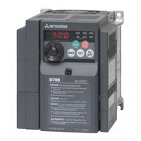
Mitsubishi Electric FR-D700 Series Instruction Manual (290 pages)
Brand: Mitsubishi Electric
|
Category: Inverter
|
Size: 14.63 MB
Table of Contents
-
Instruction Manual
1
-
Table of Contents
5
-
1 Outline
13
-
Product Checking and Parts Identification
13
-
Front Cover
13
-
Inverter and Peripheral Devices
14
-
Peripheral Devices
15
-
-
Removal and Reinstallation of the Cover
16
-
Front Cover
16
-
Wiring Cover
17
-
-
Installation of the Inverter and Enclosure Design
18
-
Inverter Installation Environment
18
-
Cooling System Types for Inverter Panel
20
-
Inverter Placement
21
-
-
-
2 Wiring
24
-
Terminal Connection Diagram
25
-
Wiring
25
-
Main Circuit Terminal Specifications
26
-
Specification of Main Circuit Terminal
26
-
Terminal Arrangement of the Main Circuit Terminal, Power Supply and the Motor Wiring
26
-
Cables and Wiring Length
27
-
-
Control Circuit Specifications
30
-
Control Circuit Terminal
30
-
Changing the Control Logic
32
-
Connection of Stand-Alone Option Unit
32
-
Wiring of Control Circuit
34
-
Wiring Instructions
36
-
Connection to the PU Connector
37
-
-
Connection of Stand-Alone Option Unit
39
-
Connection of a Dedicated External Brake Resistor (MRS Type, FR-ABR) (FR-D740-012 or More, FR-D720S-025 or More)
39
-
Connection of the Brake Unit (FR-BU2)
41
-
Connection of the High Power Factor Converter (FR-HC)
42
-
Connection of the Power Regeneration Common Converter (FR-CV)
43
-
Connection of a DC Reactor (FR-HEL)
43
-
-
-
3 Precautions for Use of the Inverter
44
-
EMC and Leakage Currents
45
-
Leakage Currents and Countermeasures
45
-
Inverter-Driven 400V Class Motor
45
-
EMC Measures
47
-
Power Supply Harmonics
49
-
Installation of Power Factor Improving Reactor
50
-
Power-Off and Magnetic Contactor (MC)
51
-
Inverter-Driven 400V Class Motor
52
-
Precautions for Use of the Inverter
53
-
Failsafe of the System Which Uses the Inverter
55
-
-
4 Parameters
58
-
Operation Panel
59
-
Names and Functions of the Operation Panel
59
-
Basic Operation (Factory Setting)
60
-
Easy Operation Mode Setting (Easy Setting Mode)
61
-
Change the Parameter Setting Value
62
-
Setting Dial Push
62
-
-
Parameter List
63
-
Limit the Output Frequency
70
-
Frequency Setting by External Terminals
70
-
Selection and Protection of a Motor
70
-
Motor Brake and Stop Operation
70
-
Function Assignment of External Terminal and Control
70
-
Monitor Display and Monitor Output Signal
71
-
Operation Setting at Fault Occurrence
71
-
Selection of Operation Mode and Operation Location
71
-
Special Operation and Frequency Control
72
-
Initial Value Change List
72
-
Check and Clear of the Faults History
72
-
-
Adjust the Output Torque (Current) of the Motor
73
-
Manual Torque Boost (Pr. 0, Pr. 46)
73
-
General-Purpose Magnetic Flux Vector Control (Pr. 71, Pr. 80)
74
-
Test Run
75
-
Slip Compensation (Pr. 245 to Pr. 247)
77
-
Stall Prevention Operation (Pr. 22, Pr. 23, Pr. 48, Pr. 66, Pr. 156, Pr. 157)
78
-
-
Limit the Output Frequency
82
-
Maximum/Minimum Frequency (Pr. 1, Pr. 2, Pr. 18)
82
-
Avoid Mechanical Resonance Points (Frequency Jumps) (Pr. 31 to Pr. 36)
83
-
-
Set V/F Pattern
84
-
Base Frequency, Voltage (Pr. 3, Pr. 19, Pr. 47)
84
-
Load Pattern Selection (Pr. 14)
86
-
-
Frequency Setting by External Terminals
88
-
Operation by Multi-Speed Operation (Pr. 4 to Pr. 6, Pr. 24 to Pr. 27, Pr. 232 to Pr. 239)
88
-
Jog Operation (Pr. 15, Pr. 16)
90
-
Remote Setting Function (Pr. 59)
92
-
-
Setting of Acceleration/Deceleration Time and Acceleration/ Deceleration Pattern
95
-
Setting of the Acceleration and Deceleration Time (Pr. 7, Pr. 8, Pr. 20, Pr. 44, Pr. 45)
95
-
Starting Frequency and Start-Time Hold Function (Pr. 13, Pr. 571)
97
-
Acceleration/Deceleration Pattern (Pr. 29)
98
-
Selection and Protection of a Motor
99
-
Motor Overheat Protection (Electronic Thermal O/L Relay, PTC Thermistor Protection) (Pr. 9, Pr. 51, Pr. 561)
99
-
Applied Motor (Pr. 71, Pr. 450)
102
-
To Exhibit the Best Performance of the Motor Performance (Offline Auto Tuning) (Pr. 71, Pr. 80, Pr. 82 to Pr. 84, Pr. 90, Pr. 96)
104
-
-
Motor Brake and Stop Operation
108
-
DC Injection Brake (Pr. 10 to Pr. 12)
108
-
Selection of a Regenerative Brake (Pr. 30, Pr. 70)
109
-
Stop Selection (Pr. 250)
111
-
-
Function Assignment of External Terminal and Control
112
-
Input Terminal Function Selection (Pr. 178 to Pr. 182)
112
-
Inverter Output Shutoff Signal (MRS Signal, Pr. 17)
114
-
Condition Selection of Function Validity by Second Function Selection Signal (RT)
115
-
Start Signal Operation Selection (STF, STR, STOP Signal, Pr. 250)
116
-
Output Terminal Function Selection (Pr. 190, Pr. 192)
118
-
Detection of Output Frequency (SU, FU Signal, Pr. 41 to Pr. 43)
122
-
Output Current Detection Function (Y12 Signal, Y13 Signal, Pr. 150 to Pr. 153, Pr. 166, Pr. 167)
123
-
Remote Output Selection (REM Signal, Pr. 495, Pr. 496)
125
-
-
Monitor Display and Monitor Output Signal
126
-
Speed Display and Speed Setting (Pr. 37)
126
-
Monitor Display Selection of Operation Panel/Pu and Terminal am (Pr. 52, Pr.158, Pr. 170, Pr. 171, Pr. 268, Pr. 563, Pr. 564, Pr. 891)
127
-
Reference of the Terminal am (Analog Voltage Output) (Pr. 55, Pr. 56)
132
-
Terminal am Calibration (Calibration Parameter C1 (Pr.901))
133
-
-
Operation Selection at Power Failure and Instantaneous Power Failure
135
-
Automatic Restart after Instantaneous Power Failure/Flying Start (Pr. 30, Pr. 57, Pr. 58, Pr. 96, Pr. 162, Pr. 165, Pr. 298, Pr. 299, Pr. 611)
135
-
Power-Failure Deceleration Stop Function (Pr. 261)
141
-
-
Operation Setting at Fault Occurrence
143
-
Retry Function (Pr. 65, Pr. 67 to Pr. 69)
143
-
Input/Output Phase Loss Protection Selection (Pr. 251, Pr. 872)
145
-
Earth (Ground) Fault Detection at Start (Pr. 249)
145
-
-
Energy Saving Operation
146
-
Optimum Excitation Control (Pr. 60)
146
-
-
-
Motor Noise, EMI Measures, Mechanical Resonance
147
-
PWM Carrier Frequency and Soft-PWM Control (Pr. 72, Pr. 240, Pr. 260)
147
-
Speed Smoothing Control (Pr. 653)
148
-
-
Frequency Setting by Analog Input (Terminal 2, 4)
149
-
Analog Input Selection (Pr. 73, Pr. 267)
149
-
Response Level of Analog Input and Noise Elimination (Pr. 74)
151
-
Bias and Gain of Frequency Setting Voltage (Current) (Pr. 125, Pr. 126, Pr. 241, C2 (Pr. 902) to C7 (Pr. 905))
152
-
-
Misoperation Prevention and Parameter Setting Restriction
157
-
Reset Selection/Disconnected PU Detection/Pu Stop Selection (Pr. 75)
157
-
Parameter Write Disable Selection (Pr. 77)
157
-
Parameter Write Disable Selection (Pr. 77)
160
-
Reverse Rotation Prevention Selection (Pr. 78)
161
-
Extended Parameter Display (Pr. 160)
161
-
Password Function (Pr. 296, Pr. 297)
162
-
-
Selection of Operation Mode and Operation Location
164
-
Operation Mode Selection (Pr. 79)
164
-
Operation Mode at Power-On (Pr. 79, Pr. 340)
164
-
Operation Mode at Power-On (Pr. 79, Pr. 340)
174
-
Start Command Source and Frequency Command Source During Communication Operation (Pr. 338, Pr. 339, Pr. 551)
175
-
-
Communication Operation and Setting
179
-
Wiring and Configuration of PU Connector
179
-
Initial Settings and Specifications of RS-485 Communication (Pr. 117 to Pr. 120, Pr. 123, Pr. 124, Pr. 549)
182
-
Operation Selection at Communication Error Occurrence (Pr. 121, Pr. 122, Pr. 502)
183
-
Communication EEPROM Write Selection (Pr. 342)
186
-
Mitsubishi Inverter Protocol (Computer Link Communication)
187
-
Run Command
197
-
Modbus RTU Communication Specifications (Pr. 117, Pr. 118, Pr. 120, Pr. 122, Pr. 343, Pr. 502, Pr. 549)
199
-
Modbus RTU Communication Specifications
199
-
-
Special Operation and Frequency Control
211
-
PID Control (Pr. 127 to Pr. 134, Pr. 575 to Pr. 577)
211
-
Dancer Control (Pr. 44, Pr. 45, Pr. 128 to Pr. 134)
219
-
Traverse Function (Pr. 592 to Pr. 597)
225
-
Regeneration Avoidance Function (Pr. 665, Pr. 882, Pr. 883, Pr. 885, Pr. 886)
227
-
-
Useful Functions
229
-
Cooling Fan Operation Selection (Pr. 244)
229
-
Display of the Life of the Inverter Parts (Pr. 255 to Pr. 259)
230
-
Maintenance Timer Alarm (Pr. 503, Pr. 504)
234
-
Current Average Value Monitor Signal (Pr. 555 to Pr. 557)
235
-
Free Parameter (Pr. 888, Pr. 889)
237
-
-
Setting from the Parameter Unit and Operation Panel
238
-
RUN Key Rotation Direction Selection (Pr. 40)
238
-
PU Display Language Selection(Pr.145)
238
-
Operation Panel Frequency Setting/Key Lock Operation Selection (Pr. 161)
239
-
Magnitude of Frequency Change Setting (Pr. 295)
241
-
Buzzer Control (Pr. 990)
242
-
PU Contrast Adjustment (Pr. 991)
242
-
-
Parameter Clear/ All Parameter Clear
243
-
Initial Value Change List
244
-
Check and Clear of the Faults History
245
-
-
5 Troubleshooting
247
-
Reset Method of Protective Function
248
-
List of Fault or Alarm Indications
249
-
Causes and Corrective Actions
250
-
Correspondences between Digital and Actual Characters
258
-
Check First When You Have some Troubles
259
-
Motor will Not Start
259
-
Motor Generates Abnormal Noise
259
-
Motor Generates Heat Abnormally
260
-
Motor Rotates in Opposite Direction
260
-
Speed Greatly Differs from the Setting
260
-
Acceleration/Deceleration Is Not Smooth
260
-
Motor Current Is Large
260
-
Speed Does Not Increase
260
-
Speed Varies During Operation
261
-
Operation Mode Is Not Changed Properly
261
-
Operation Panel Display Is Not Operating
261
-
Parameter Write Cannot be Performed
261
-
-
-
6 Precautions for Maintenance and Inspection
264
-
Inspection Items
264
-
Daily Inspection
264
-
Periodic Inspection
264
-
Daily and Periodic Inspection
265
-
Display of the Life of the Inverter Parts
266
-
Checking the Inverter and Converter Modules
266
-
Cleaning
266
-
Replacement of Parts
267
-
-
Measurement of Main Circuit Voltages, Currents and Powers
271
-
Measurement of Powers
273
-
Measurement of Voltages and Use of PT
273
-
Measurement of Currents
274
-
Use of CT and Transducer
274
-
Measurement of Inverter Input Power Factor
274
-
Measurement of Converter Output Voltage (Across Terminals + and -)
274
-
Insulation Resistance Test Using Megger
275
-
Pressure Test
275
-
-
-
7 Specifications
277
-
Rating
278
-
Inverter Rating
278
-
-
Common Specifications
279
-
Outline Dimension Drawings
280
-
-
Appendix
283
-
Appendix1 Index
284
-
-
Mitsubishi Electric FR-D700 Series Installation Manuallines (104 pages)
EMC
Brand: Mitsubishi Electric
|
Category: Inverter
|
Size: 3.11 MB
Table of Contents
-
Table of Contents
3
-
Introduction
4
-
Compliance to the EMC Directive of the Inverter
5
-
EMC Measures
8
-
Basics of the EMC Measures
8
-
Precaution for Inverter Mounting to the Enclosure
9
-
Precaution for Wiring
11
-
Others Precautions
15
-
-
EMC Measure Options
16
-
EMC Directive Compliant EMC Filter
16
-
Other Precautions
19
-
List of the EMC Directive Compliant Filters and Their Applicable Inverters
22
-
-
EMC Data
24
-
Fr-A720
24
-
Fr-A740
32
-
Fr-A741
44
-
Fr-F720
51
-
Fr-F740
59
-
Fr-E720
71
-
Fr-E740
78
-
Fr-E720S
84
-
Fr-D720
88
-
Fr-D740
93
-
Fr-D720S
99
-
Advertisement

Mitsubishi Electric FR-D700 Series Manual (34 pages)
Brand: Mitsubishi Electric
|
Category: Inverter
|
Size: 3.5 MB
Table of Contents
-
New Standard of Inverter
2
-
Mitsubishi’s New Standard
2
-
Contents
2
-
Easy Use and Time Saving Built-In as Standard
3
-
Easy Maintenance
3
-
Environment Consciousness in Global Standard
3
-
Lineup
3
-
Standard Specifications
4
-
Rating
4
-
Three-Phase 200V Power Supply
4
-
Three-Phase 400V Power Supply
4
-
Single-Phase 200V Power Supply
5
-
Single-Phase 100V Power Supply
5
-
Common Specifications
6
-
Outline Dimension Drawings
7
-
Parameter Unit (Option) (FR-PU07)
9
-
Parameter Unit with Battery Pack (Option) (FR-PU07BB (-L))
9
-
Enclosure Surface Operation Panel (Option) (FR-PA07)
9
-
Terminal Connection Diagram
10
-
Control Circuit
10
-
Terminal Specification Explanation
11
-
Explanation of the Operation Panel
12
-
Basic Operation of the Operation Panel
13
-
Explanations of Parameter Unit
14
-
Parameter Unit (FR-PU07), Parameter Unit with Battery Pack (FR-PU07BB(-L) (Available Soon))
14
-
Main Functions
14
-
Parameter List
15
-
Protective Functions
22
-
Option and Peripheral Devices
23
-
Option List
23
-
Peripheral Devices/Cable Size List
24
-
Selecting the Rated Sensitivity Current for the Earth Leakage Current Breaker
25
-
Precautions for Operation/Selection
26
-
Precautions for Use of the Inverter
26
-
Power Supply
26
-
Setting
26
-
Precautions for Selection
27
-
Precautions for Peripheral Device Selection
28
-
Installation and Selection of Moulded Case Circuit Breaker
28
-
Handling of the Inverter Input Side Magnetic Contactor
28
-
Wire Thickness and Wiring Distance
28
-
Earth (Ground)
29
-
Noise
29
-
Leakage Currents
29
-
Harmonic Suppression Guideline
30
-
Calculation of Outgoing Harmonic Current
30
-
FR-D700 Series Specification Difference List
31
-
International FA Center
33
Mitsubishi Electric FR-D700 Series Instruction Manual (60 pages)
Brand: Mitsubishi Electric
|
Category: Inverter
|
Size: 4.54 MB
Table of Contents
-
Table of Contents
1
-
1 Outline
5
-
Installation and Wiring
9
-
-
3 Precautions for Use of the Inverter
23
-
Failsafe of the System Which Uses the Inverter
26
-
Driving the Motor
27
-
-
6 Energy Saving Operation for Fans and Pumps
35
-
Parameters
36
-
Troubleshooting
40
-
-
9 Precautions for Maintenance and Inspection
45
-
10 Specifications
47
Mitsubishi Electric FR-D700 Series Installation Manuallines (28 pages)
Brand: Mitsubishi Electric
|
Category: Inverter
|
Size: 2.09 MB
Table of Contents
-
Table of Contents
1
-
Product Checking and Parts Identification
4
-
Outline Dimension Drawings
6
-
Wiring
7
-
Main Circuit Terminal Specifications
8
-
Cables and Wiring Length
9
-
Control Circuit Specifications
11
-
-
Precautions for Use of the Inverter
13
-
Failsafe of the System Which Uses the Inverter
15
-
Parameter List
16
-
Troubleshooting
21
-
List of Fault or Alarm Indications
22
-
Appendix 2 Instructions for Ul and Cul
26
-
Motor Overload Protection
27
-
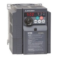
Mitsubishi Electric FR-D700 Series Installation Manuallines (28 pages)
Brand: Mitsubishi Electric
|
Category: Inverter
|
Size: 2.11 MB
Table of Contents
-
Table of Contents
1
-
Product Checking and Parts Identification
4
-
Outline Dimension Drawings
6
-
Wiring
7
-
Precautions for Use of the Inverter
13
-
Failsafe of the System Which Uses the Inverter
15
-
Parameter List
16
-
Troubleshooting
21
Mitsubishi Electric FR-D700 Series Safety Stop Function Instruction Manual (14 pages)
Brand: Mitsubishi Electric
|
Category: Inverter
|
Size: 0.36 MB
Table of Contents
-
Table of Contents
1
-
General Description
3
-
Installation and Wiring
4
-
Example of Safety System Configuration
7
-
Test and Checking Failure
11
-
Safety Parameters of FR-D700
12
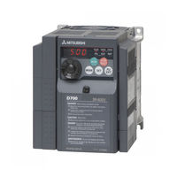
Mitsubishi Electric FR-D700 Series Instruction Manual (14 pages)
INVERTER
Brand: Mitsubishi Electric
|
Category: Inverter
|
Size: 0.33 MB
Table of Contents
-
General Description
3
-
Installation and Wiring
4
-
Example of Safety System Configuration
7
-
Test and Checking Failure
11

Mitsubishi Electric FR-D700 Series Instruction Manual (13 pages)
Brand: Mitsubishi Electric
|
Category: Inverter
|
Size: 0.48 MB
Table of Contents
-
Instruction Manual
1
-
General Description
4
-
Installation and Wiring
5
-
Example of Safety System Configuration
8
-
Test and Checking Failure
11

Mitsubishi Electric FR-D700 Series Instruction Manual (11 pages)
Brand: Mitsubishi Electric
|
Category: Inverter
|
Size: 1.48 MB
Table of Contents
-
Product Checking and Parts Identification
5
-
Changing the Parameter Setting Value
8
-
Operation Display
8
-
Installation and Wiring
10
Mitsubishi Electric FR-D700 Series Instruction Manual (11 pages)
Safety stop function
Brand: Mitsubishi Electric
|
Category: Inverter
|
Size: 0.22 MB
Table of Contents
-
General Description
3
-
Installation and Wiring
4
-
Example of Safety System Configuration
7
-
Test and Checking Failure
10

Mitsubishi Electric FR-D700 Series Instruction Manual (4 pages)
Brand: Mitsubishi Electric
|
Category: DC Drives
|
Size: 1.07 MB
Advertisement
Related Products
-
Mitsubishi Electric FR-D740-7.5K-EA
-
Mitsubishi Electric FR-D720-2.2K
-
Mitsubishi Electric FR-D720-7.5K
-
Mitsubishi Electric FR-D740-15K
-
Mitsubishi Electric FR-D740-7.5K
-
Mitsubishi Electric FR-D740-11K
-
Mitsubishi Electric FR-D740-022-EC
-
Mitsubishi Electric FR-D720S-100-EC
-
Mitsubishi Electric FR-D720S-025-EC
-
Mitsubishi Electric FR-D740-012-EC
Mitsubishi Electric Categories
![]()
Air Conditioner
Controller
![]()
Projector
Inverter
Heat Pump
More Mitsubishi Electric Manuals
- Manuals
- Brands
- Mitsubishi Electric Manuals
- Inverter
- FR-D700 Series
Manuals and User Guides for Mitsubishi Electric FR-D700 Series. We have 13 Mitsubishi Electric FR-D700 Series manuals available for free PDF download: Technical Manual, Instruction Manual, Installation Manuallines, Manual, Safety Stop Function Instruction Manual
Mitsubishi Electric FR-D700 Series Technical Manual (550 pages)
Brand: Mitsubishi Electric
|
Category: Inverter
|
Size: 25.55 MB
Table of Contents
-
3 Selection 475
6
-
Table of Contents
6
-
Common Specifications
15
-
Internal Block Diagram
31
-
Control Circuit
32
-
Wiring and Configuration of Pu Connector
88
-
Usb Connector
92
-
Protective Functions
103
-
Precautions for Use of the Inverter
121
-
-
2 Parameter
126
-
Parameter
127
-
Parameter List
127
-
List of Parameters Classified by Purpose of Use
168
-
Operation Mode
175
-
Frequency Setting
180
-
Analog Input
187
-
Initial Setting
190
-
-
Output Frequency and Acceleration/Deceleration Time
198
-
Setting Output Voltage (V/F Control)
210
-
Selection of Control Method
218
-
Vector Control
222
-
Flux Vector Control
223
-
Inverter Type
230
-
-
-
Applied Motor Selection and Auto Tuning
232
-
Speed Control by Real Sensorless Vector Control and Vector Control
246
-
Torque Control by Real Sensorless Vector Control and Vector Control
264
-
Position Control by Vector Control
274
-
Adjustment of Real Sensorless Vector Control, Vector Control
286
-
Selection of DC Injection Brake and Regenerative Brake
294
-
Stall Prevention Operation and Regeneration Avoidance Operation
301
-
Monitor Display and Monitor Output Signal
309
-
Operation Selection at Power Failure and Instantaneous Power Failure
333
-
Parameter Setting
337
-
-
Alarm Function
342
-
Misoperation Prevention and Parameter Setting and PU Setting
348
-
Frequency Compensation Function
357
-
Other Function
361
-
Specification List
397
-
Communication Operation
400
-
Rating
447
-
-
Motor Characteristics
457
-
Motor Types According to Protection Structure
460
-
Constant-Torque Motor
460
-
Brake Motor
463
-
Pole Changing Motor
463
-
Submersible Motor
463
-
Explosion-Proof Motor
464
-
Vector Control Dedicated Motor
467
-
Geared Motor
469
-
Synchronous Motor
470
-
Single Phase Motor
470
-
Permissible Maximum Frequency of General-Purpose Motor
470
-
Inverter-Driven 400V Motor
470
-
Inverter Input Current and Power Factor
471
-
Improvement of Power Factor
472
-
Inrush Current
472
-
Power Supply Voltage Variation
473
-
Imbalanced Power Supply Voltage
473
-
Coordination with Power Supply
473
-
Differences between Emi and Harmonics
474
-
Power Harmonics and Their Reduction Techniques
474
-
Inverter-Generated Emi and Their Reduction Techniques
484
-
Leakage Currents and Countermeasures
490
-
-
Selection of Peripheral Devices
492
-
Moulded Case Circuit Breaker
494
-
Magnetic Contactor (MC)
495
-
Thermal Relay
495
-
Cable Size and Wiring Distance
496
-
Earth Leakage Circuit Breaker (Nv)
497
-
Start/Stop Switch
499
-
Frequency Setting Potentiometer
500
-
Frequency Meter and Calibration Resistor
500
-
Twisted/Shielded Cables
501
-
Notes on Installation of Inverter in an Enclosure
502
-
-
Enclosure Design
509
-
Inverter Installation Environment
509
-
Heat Generated by Inverter and Related Devices
511
-
Specification of Enclosed Enclosure
514
-
Cooling of Inverter Enclosure
515
-
Measurement of Powers
516
-
Measurement of Voltages and Use of Pt
516
-
-
Meters and Measurement Methods
516
-
Measurement of Currents
517
-
Use of Ct and Transducer
517
-
Measurement of Inverter Input Power Factor
517
-
Measurement of Converter Output Voltage (Across Terminals P-N)
517
-
Measurement of Inverter Output Frequency
517
-
Compliance with the Ul and Csa Standards
518
-
Compliance with the Eu Directives
520
-
Instantaneous Power Failure
536
-
Frequency Setting Potentiometer
538
-
-
Advertisement
Mitsubishi Electric FR-D700 Series Instruction Manual (290 pages)
Brand: Mitsubishi Electric
|
Category: Inverter
|
Size: 14.63 MB
Table of Contents
-
Instruction Manual
1
-
Table of Contents
5
-
1 Outline
13
-
Product Checking and Parts Identification
13
-
Front Cover
13
-
Inverter and Peripheral Devices
14
-
Peripheral Devices
15
-
-
Removal and Reinstallation of the Cover
16
-
Front Cover
16
-
Wiring Cover
17
-
-
Installation of the Inverter and Enclosure Design
18
-
Inverter Installation Environment
18
-
Cooling System Types for Inverter Panel
20
-
Inverter Placement
21
-
-
-
2 Wiring
24
-
Terminal Connection Diagram
25
-
Wiring
25
-
Main Circuit Terminal Specifications
26
-
Specification of Main Circuit Terminal
26
-
Terminal Arrangement of the Main Circuit Terminal, Power Supply and the Motor Wiring
26
-
Cables and Wiring Length
27
-
-
Control Circuit Specifications
30
-
Control Circuit Terminal
30
-
Changing the Control Logic
32
-
Connection of Stand-Alone Option Unit
32
-
Wiring of Control Circuit
34
-
Wiring Instructions
36
-
Connection to the PU Connector
37
-
-
Connection of Stand-Alone Option Unit
39
-
Connection of a Dedicated External Brake Resistor (MRS Type, FR-ABR) (FR-D740-012 or More, FR-D720S-025 or More)
39
-
Connection of the Brake Unit (FR-BU2)
41
-
Connection of the High Power Factor Converter (FR-HC)
42
-
Connection of the Power Regeneration Common Converter (FR-CV)
43
-
Connection of a DC Reactor (FR-HEL)
43
-
-
-
3 Precautions for Use of the Inverter
44
-
EMC and Leakage Currents
45
-
Leakage Currents and Countermeasures
45
-
Inverter-Driven 400V Class Motor
45
-
EMC Measures
47
-
Power Supply Harmonics
49
-
Installation of Power Factor Improving Reactor
50
-
Power-Off and Magnetic Contactor (MC)
51
-
Inverter-Driven 400V Class Motor
52
-
Precautions for Use of the Inverter
53
-
Failsafe of the System Which Uses the Inverter
55
-
-
4 Parameters
58
-
Operation Panel
59
-
Names and Functions of the Operation Panel
59
-
Basic Operation (Factory Setting)
60
-
Easy Operation Mode Setting (Easy Setting Mode)
61
-
Change the Parameter Setting Value
62
-
Setting Dial Push
62
-
-
Parameter List
63
-
Limit the Output Frequency
70
-
Frequency Setting by External Terminals
70
-
Selection and Protection of a Motor
70
-
Motor Brake and Stop Operation
70
-
Function Assignment of External Terminal and Control
70
-
Monitor Display and Monitor Output Signal
71
-
Operation Setting at Fault Occurrence
71
-
Selection of Operation Mode and Operation Location
71
-
Special Operation and Frequency Control
72
-
Initial Value Change List
72
-
Check and Clear of the Faults History
72
-
-
Adjust the Output Torque (Current) of the Motor
73
-
Manual Torque Boost (Pr. 0, Pr. 46)
73
-
General-Purpose Magnetic Flux Vector Control (Pr. 71, Pr. 80)
74
-
Test Run
75
-
Slip Compensation (Pr. 245 to Pr. 247)
77
-
Stall Prevention Operation (Pr. 22, Pr. 23, Pr. 48, Pr. 66, Pr. 156, Pr. 157)
78
-
-
Limit the Output Frequency
82
-
Maximum/Minimum Frequency (Pr. 1, Pr. 2, Pr. 18)
82
-
Avoid Mechanical Resonance Points (Frequency Jumps) (Pr. 31 to Pr. 36)
83
-
-
Set V/F Pattern
84
-
Base Frequency, Voltage (Pr. 3, Pr. 19, Pr. 47)
84
-
Load Pattern Selection (Pr. 14)
86
-
-
Frequency Setting by External Terminals
88
-
Operation by Multi-Speed Operation (Pr. 4 to Pr. 6, Pr. 24 to Pr. 27, Pr. 232 to Pr. 239)
88
-
Jog Operation (Pr. 15, Pr. 16)
90
-
Remote Setting Function (Pr. 59)
92
-
-
Setting of Acceleration/Deceleration Time and Acceleration/ Deceleration Pattern
95
-
Setting of the Acceleration and Deceleration Time (Pr. 7, Pr. 8, Pr. 20, Pr. 44, Pr. 45)
95
-
Starting Frequency and Start-Time Hold Function (Pr. 13, Pr. 571)
97
-
Acceleration/Deceleration Pattern (Pr. 29)
98
-
Selection and Protection of a Motor
99
-
Motor Overheat Protection (Electronic Thermal O/L Relay, PTC Thermistor Protection) (Pr. 9, Pr. 51, Pr. 561)
99
-
Applied Motor (Pr. 71, Pr. 450)
102
-
To Exhibit the Best Performance of the Motor Performance (Offline Auto Tuning) (Pr. 71, Pr. 80, Pr. 82 to Pr. 84, Pr. 90, Pr. 96)
104
-
-
Motor Brake and Stop Operation
108
-
DC Injection Brake (Pr. 10 to Pr. 12)
108
-
Selection of a Regenerative Brake (Pr. 30, Pr. 70)
109
-
Stop Selection (Pr. 250)
111
-
-
Function Assignment of External Terminal and Control
112
-
Input Terminal Function Selection (Pr. 178 to Pr. 182)
112
-
Inverter Output Shutoff Signal (MRS Signal, Pr. 17)
114
-
Condition Selection of Function Validity by Second Function Selection Signal (RT)
115
-
Start Signal Operation Selection (STF, STR, STOP Signal, Pr. 250)
116
-
Output Terminal Function Selection (Pr. 190, Pr. 192)
118
-
Detection of Output Frequency (SU, FU Signal, Pr. 41 to Pr. 43)
122
-
Output Current Detection Function (Y12 Signal, Y13 Signal, Pr. 150 to Pr. 153, Pr. 166, Pr. 167)
123
-
Remote Output Selection (REM Signal, Pr. 495, Pr. 496)
125
-
-
Monitor Display and Monitor Output Signal
126
-
Speed Display and Speed Setting (Pr. 37)
126
-
Monitor Display Selection of Operation Panel/Pu and Terminal am (Pr. 52, Pr.158, Pr. 170, Pr. 171, Pr. 268, Pr. 563, Pr. 564, Pr. 891)
127
-
Reference of the Terminal am (Analog Voltage Output) (Pr. 55, Pr. 56)
132
-
Terminal am Calibration (Calibration Parameter C1 (Pr.901))
133
-
-
Operation Selection at Power Failure and Instantaneous Power Failure
135
-
Automatic Restart after Instantaneous Power Failure/Flying Start (Pr. 30, Pr. 57, Pr. 58, Pr. 96, Pr. 162, Pr. 165, Pr. 298, Pr. 299, Pr. 611)
135
-
Power-Failure Deceleration Stop Function (Pr. 261)
141
-
-
Operation Setting at Fault Occurrence
143
-
Retry Function (Pr. 65, Pr. 67 to Pr. 69)
143
-
Input/Output Phase Loss Protection Selection (Pr. 251, Pr. 872)
145
-
Earth (Ground) Fault Detection at Start (Pr. 249)
145
-
-
Energy Saving Operation
146
-
Optimum Excitation Control (Pr. 60)
146
-
-
-
Motor Noise, EMI Measures, Mechanical Resonance
147
-
PWM Carrier Frequency and Soft-PWM Control (Pr. 72, Pr. 240, Pr. 260)
147
-
Speed Smoothing Control (Pr. 653)
148
-
-
Frequency Setting by Analog Input (Terminal 2, 4)
149
-
Analog Input Selection (Pr. 73, Pr. 267)
149
-
Response Level of Analog Input and Noise Elimination (Pr. 74)
151
-
Bias and Gain of Frequency Setting Voltage (Current) (Pr. 125, Pr. 126, Pr. 241, C2 (Pr. 902) to C7 (Pr. 905))
152
-
-
Misoperation Prevention and Parameter Setting Restriction
157
-
Reset Selection/Disconnected PU Detection/Pu Stop Selection (Pr. 75)
157
-
Parameter Write Disable Selection (Pr. 77)
157
-
Parameter Write Disable Selection (Pr. 77)
160
-
Reverse Rotation Prevention Selection (Pr. 78)
161
-
Extended Parameter Display (Pr. 160)
161
-
Password Function (Pr. 296, Pr. 297)
162
-
-
Selection of Operation Mode and Operation Location
164
-
Operation Mode Selection (Pr. 79)
164
-
Operation Mode at Power-On (Pr. 79, Pr. 340)
164
-
Operation Mode at Power-On (Pr. 79, Pr. 340)
174
-
Start Command Source and Frequency Command Source During Communication Operation (Pr. 338, Pr. 339, Pr. 551)
175
-
-
Communication Operation and Setting
179
-
Wiring and Configuration of PU Connector
179
-
Initial Settings and Specifications of RS-485 Communication (Pr. 117 to Pr. 120, Pr. 123, Pr. 124, Pr. 549)
182
-
Operation Selection at Communication Error Occurrence (Pr. 121, Pr. 122, Pr. 502)
183
-
Communication EEPROM Write Selection (Pr. 342)
186
-
Mitsubishi Inverter Protocol (Computer Link Communication)
187
-
Run Command
197
-
Modbus RTU Communication Specifications (Pr. 117, Pr. 118, Pr. 120, Pr. 122, Pr. 343, Pr. 502, Pr. 549)
199
-
Modbus RTU Communication Specifications
199
-
-
Special Operation and Frequency Control
211
-
PID Control (Pr. 127 to Pr. 134, Pr. 575 to Pr. 577)
211
-
Dancer Control (Pr. 44, Pr. 45, Pr. 128 to Pr. 134)
219
-
Traverse Function (Pr. 592 to Pr. 597)
225
-
Regeneration Avoidance Function (Pr. 665, Pr. 882, Pr. 883, Pr. 885, Pr. 886)
227
-
-
Useful Functions
229
-
Cooling Fan Operation Selection (Pr. 244)
229
-
Display of the Life of the Inverter Parts (Pr. 255 to Pr. 259)
230
-
Maintenance Timer Alarm (Pr. 503, Pr. 504)
234
-
Current Average Value Monitor Signal (Pr. 555 to Pr. 557)
235
-
Free Parameter (Pr. 888, Pr. 889)
237
-
-
Setting from the Parameter Unit and Operation Panel
238
-
RUN Key Rotation Direction Selection (Pr. 40)
238
-
PU Display Language Selection(Pr.145)
238
-
Operation Panel Frequency Setting/Key Lock Operation Selection (Pr. 161)
239
-
Magnitude of Frequency Change Setting (Pr. 295)
241
-
Buzzer Control (Pr. 990)
242
-
PU Contrast Adjustment (Pr. 991)
242
-
-
Parameter Clear/ All Parameter Clear
243
-
Initial Value Change List
244
-
Check and Clear of the Faults History
245
-
-
5 Troubleshooting
247
-
Reset Method of Protective Function
248
-
List of Fault or Alarm Indications
249
-
Causes and Corrective Actions
250
-
Correspondences between Digital and Actual Characters
258
-
Check First When You Have some Troubles
259
-
Motor will Not Start
259
-
Motor Generates Abnormal Noise
259
-
Motor Generates Heat Abnormally
260
-
Motor Rotates in Opposite Direction
260
-
Speed Greatly Differs from the Setting
260
-
Acceleration/Deceleration Is Not Smooth
260
-
Motor Current Is Large
260
-
Speed Does Not Increase
260
-
Speed Varies During Operation
261
-
Operation Mode Is Not Changed Properly
261
-
Operation Panel Display Is Not Operating
261
-
Parameter Write Cannot be Performed
261
-
-
-
6 Precautions for Maintenance and Inspection
264
-
Inspection Items
264
-
Daily Inspection
264
-
Periodic Inspection
264
-
Daily and Periodic Inspection
265
-
Display of the Life of the Inverter Parts
266
-
Checking the Inverter and Converter Modules
266
-
Cleaning
266
-
Replacement of Parts
267
-
-
Measurement of Main Circuit Voltages, Currents and Powers
271
-
Measurement of Powers
273
-
Measurement of Voltages and Use of PT
273
-
Measurement of Currents
274
-
Use of CT and Transducer
274
-
Measurement of Inverter Input Power Factor
274
-
Measurement of Converter Output Voltage (Across Terminals + and -)
274
-
Insulation Resistance Test Using Megger
275
-
Pressure Test
275
-
-
-
7 Specifications
277
-
Rating
278
-
Inverter Rating
278
-
-
Common Specifications
279
-
Outline Dimension Drawings
280
-
-
Appendix
283
-
Appendix1 Index
284
-
-
Mitsubishi Electric FR-D700 Series Installation Manuallines (104 pages)
EMC
Brand: Mitsubishi Electric
|
Category: Inverter
|
Size: 3.11 MB
Table of Contents
-
Table of Contents
3
-
Introduction
4
-
Compliance to the EMC Directive of the Inverter
5
-
EMC Measures
8
-
Basics of the EMC Measures
8
-
Precaution for Inverter Mounting to the Enclosure
9
-
Precaution for Wiring
11
-
Others Precautions
15
-
-
EMC Measure Options
16
-
EMC Directive Compliant EMC Filter
16
-
Other Precautions
19
-
List of the EMC Directive Compliant Filters and Their Applicable Inverters
22
-
-
EMC Data
24
-
Fr-A720
24
-
Fr-A740
32
-
Fr-A741
44
-
Fr-F720
51
-
Fr-F740
59
-
Fr-E720
71
-
Fr-E740
78
-
Fr-E720S
84
-
Fr-D720
88
-
Fr-D740
93
-
Fr-D720S
99
-
Advertisement
Mitsubishi Electric FR-D700 Series Manual (34 pages)
Brand: Mitsubishi Electric
|
Category: Inverter
|
Size: 3.5 MB
Table of Contents
-
New Standard of Inverter
2
-
Mitsubishi’s New Standard
2
-
Contents
2
-
Easy Use and Time Saving Built-In as Standard
3
-
Easy Maintenance
3
-
Environment Consciousness in Global Standard
3
-
Lineup
3
-
Standard Specifications
4
-
Rating
4
-
Three-Phase 200V Power Supply
4
-
Three-Phase 400V Power Supply
4
-
Single-Phase 200V Power Supply
5
-
Single-Phase 100V Power Supply
5
-
Common Specifications
6
-
Outline Dimension Drawings
7
-
Parameter Unit (Option) (FR-PU07)
9
-
Parameter Unit with Battery Pack (Option) (FR-PU07BB (-L))
9
-
Enclosure Surface Operation Panel (Option) (FR-PA07)
9
-
Terminal Connection Diagram
10
-
Control Circuit
10
-
Terminal Specification Explanation
11
-
Explanation of the Operation Panel
12
-
Basic Operation of the Operation Panel
13
-
Explanations of Parameter Unit
14
-
Parameter Unit (FR-PU07), Parameter Unit with Battery Pack (FR-PU07BB(-L) (Available Soon))
14
-
Main Functions
14
-
Parameter List
15
-
Protective Functions
22
-
Option and Peripheral Devices
23
-
Option List
23
-
Peripheral Devices/Cable Size List
24
-
Selecting the Rated Sensitivity Current for the Earth Leakage Current Breaker
25
-
Precautions for Operation/Selection
26
-
Precautions for Use of the Inverter
26
-
Power Supply
26
-
Setting
26
-
Precautions for Selection
27
-
Precautions for Peripheral Device Selection
28
-
Installation and Selection of Moulded Case Circuit Breaker
28
-
Handling of the Inverter Input Side Magnetic Contactor
28
-
Wire Thickness and Wiring Distance
28
-
Earth (Ground)
29
-
Noise
29
-
Leakage Currents
29
-
Harmonic Suppression Guideline
30
-
Calculation of Outgoing Harmonic Current
30
-
FR-D700 Series Specification Difference List
31
-
International FA Center
33
Mitsubishi Electric FR-D700 Series Instruction Manual (60 pages)
Brand: Mitsubishi Electric
|
Category: Inverter
|
Size: 4.54 MB
Table of Contents
-
Table of Contents
1
-
1 Outline
5
-
Installation and Wiring
9
-
-
3 Precautions for Use of the Inverter
23
-
Failsafe of the System Which Uses the Inverter
26
-
Driving the Motor
27
-
-
6 Energy Saving Operation for Fans and Pumps
35
-
Parameters
36
-
Troubleshooting
40
-
-
9 Precautions for Maintenance and Inspection
45
-
10 Specifications
47
Mitsubishi Electric FR-D700 Series Installation Manuallines (28 pages)
Brand: Mitsubishi Electric
|
Category: Inverter
|
Size: 2.09 MB
Table of Contents
-
Table of Contents
1
-
Product Checking and Parts Identification
4
-
Outline Dimension Drawings
6
-
Wiring
7
-
Main Circuit Terminal Specifications
8
-
Cables and Wiring Length
9
-
Control Circuit Specifications
11
-
-
Precautions for Use of the Inverter
13
-
Failsafe of the System Which Uses the Inverter
15
-
Parameter List
16
-
Troubleshooting
21
-
List of Fault or Alarm Indications
22
-
Appendix 2 Instructions for Ul and Cul
26
-
Motor Overload Protection
27
-
Mitsubishi Electric FR-D700 Series Installation Manuallines (28 pages)
Brand: Mitsubishi Electric
|
Category: Inverter
|
Size: 2.11 MB
Table of Contents
-
Table of Contents
1
-
Product Checking and Parts Identification
4
-
Outline Dimension Drawings
6
-
Wiring
7
-
Precautions for Use of the Inverter
13
-
Failsafe of the System Which Uses the Inverter
15
-
Parameter List
16
-
Troubleshooting
21
Mitsubishi Electric FR-D700 Series Safety Stop Function Instruction Manual (14 pages)
Brand: Mitsubishi Electric
|
Category: Inverter
|
Size: 0.36 MB
Table of Contents
-
Table of Contents
1
-
General Description
3
-
Installation and Wiring
4
-
Example of Safety System Configuration
7
-
Test and Checking Failure
11
-
Safety Parameters of FR-D700
12
Mitsubishi Electric FR-D700 Series Instruction Manual (14 pages)
INVERTER
Brand: Mitsubishi Electric
|
Category: Inverter
|
Size: 0.33 MB
Table of Contents
-
General Description
3
-
Installation and Wiring
4
-
Example of Safety System Configuration
7
-
Test and Checking Failure
11
Mitsubishi Electric FR-D700 Series Instruction Manual (13 pages)
Brand: Mitsubishi Electric
|
Category: Inverter
|
Size: 0.48 MB
Table of Contents
-
Instruction Manual
1
-
General Description
4
-
Installation and Wiring
5
-
Example of Safety System Configuration
8
-
Test and Checking Failure
11
Mitsubishi Electric FR-D700 Series Instruction Manual (11 pages)
Brand: Mitsubishi Electric
|
Category: Inverter
|
Size: 1.48 MB
Table of Contents
-
Product Checking and Parts Identification
5
-
Changing the Parameter Setting Value
8
-
Operation Display
8
-
Installation and Wiring
10
Mitsubishi Electric FR-D700 Series Instruction Manual (11 pages)
Safety stop function
Brand: Mitsubishi Electric
|
Category: Inverter
|
Size: 0.22 MB
Table of Contents
-
General Description
3
-
Installation and Wiring
4
-
Example of Safety System Configuration
7
-
Test and Checking Failure
10
Mitsubishi Electric FR-D700 Series Instruction Manual (4 pages)
Brand: Mitsubishi Electric
|
Category: DC Drives
|
Size: 1.07 MB
Advertisement
Related Products
-
Mitsubishi Electric FR-D740-7.5K-EA
-
Mitsubishi Electric FR-D720-2.2K
-
Mitsubishi Electric FR-D720-7.5K
-
Mitsubishi Electric FR-D740-15K
-
Mitsubishi Electric FR-D740-7.5K
-
Mitsubishi Electric FR-D740-11K
-
Mitsubishi Electric FR-D740-022-EC
-
Mitsubishi Electric FR-D720S-100-EC
-
Mitsubishi Electric FR-D720S-025-EC
-
Mitsubishi Electric FR-D740-012-EC
Mitsubishi Electric Categories
![]()
Air Conditioner
Controller
![]()
Projector
Inverter
Heat Pump
More Mitsubishi Electric Manuals