В
1977 году Международная организация по
стандартизации (МОС, ISO),
состоящая из представителей индустрии
информационных и телекоммуникационных
технологий, создала комитет по разработке
коммуникационных стандартов в целях
обеспечения универсального взаимодействия
программных и аппаратных средств
множества производителей. Результатом
его работы стала эталонная модель
взаимодействия открытых систем ЭМВОС.
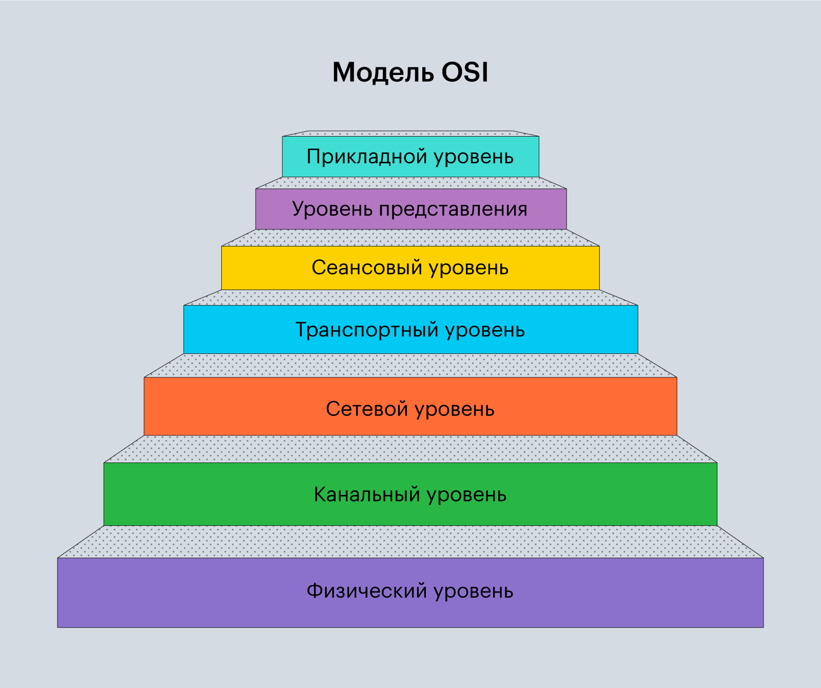
Модель определяет уровни взаимодействия
в компьютерных сетях (Рис. 1), описывает
функции, которые выполняются каждым
уровнем, но не описывает стандарты на
выполнение этих задач.
|
7 |
Прикладной (или |
|
6 |
Представительный |
|
5 |
Сеансовый (или |
|
4 |
Транспортный |
|
3 |
Сетевой (Network) |
|
2 |
Канальный (или |
|
1 |
Физический |
Рис. 2.1. Уровни
взаимодействия в сети в соответствии
с ЭМВОС (OSI)
Поскольку различные
компьютеры имеют различные скорости
передачи данных, различные форматы
данных, различные типы разъемов, разные
способы хранения и доступа к данным
(методы доступа), разные операционные
системы и организацию видов памяти, то
возникает масса не очевидных проблем
их соединения. Все эти проблемы
классифицировали и распределили по
функциональным группам – уровням ЭМВОС.
Уровни организуются
в виде вертикального стека (Рис.2.2).
Каждый уровень выполняет некоторую
группу близких функций, требуемых для
организации связи компьютеров. В
реализации более примитивных функций
он полагается на нижележащий уровень
(пользуется его услугами) и не интересуется
подробностями этой реализации. Кроме
того, каждый уровень предлагает услуги
вышестоящему уровню.
Пусть прикладной
процесс пользователя, который выполняется
в оконечной системе «А», обращается с
запросом к прикладному уровню
(Application),
например, к файловой службе. На основании
этого запроса программное обеспечение
прикладного уровня формирует сообщение
стандартного формата, которое обычно
состоит из заголовка (header)
и поля данных. Заголовок содержит
служебную информацию, которую надо
передать через сеть прикладному уровню
другого компьютера (оконечная система
«В»), чтобы сообщить ему, какие действия
требуется выполнить. Например, заголовок
должен содержать информацию о
местонахождении файла и о типе операции,
которую необходимо над ним выполнить.
Поле данных может быть пустым или
содержать какие-либо данные, например
те, которые надо записать в удаленный
файл. Для того чтобы доставить эту
информацию по назначению, предстоит
решить много задач. Но за них несут
ответственность другие нижележащие
уровни.
Рис.2.2. Архитектура
процессов в сети в соответствии с ЭМВОС
Сформированное
сообщение прикладной уровень направляет
вниз по стеку представительному уровню
(Presentation).
Программный модуль представительного
уровня на основании информации, полученной
из заголовка прикладного уровня,
выполняет требуемые действия и добавляет
к сообщению свою служебную информацию
– заголовок представительного уровня,
в котором содержатся указания для модуля
представительного уровня компьютера
– получателя. Сформированный блок
данных передается вниз по стеку сеансовому
уровню (Session),
который в свою очередь добавляет свой
заголовок и т.д. Когда сообщение достигает
нижнего физического уровня (Physical),
оно «обрастает» заголовками всех
уровней. Физический уровень обеспечивает
передачу сообщения по линии связи, то
есть через физическую среду передачи.
Когда сообщение
поступает на компьютер – получатель,
оно принимается физическим уровнем и
последовательно перемещается вверх по
стеку с уровня на уровень. Каждый уровень
анализирует и обрабатывает свой
заголовок, выполняет свои функции, затем
удаляет этот заголовок и передает
оставшийся блок данных смежному
вышележащему уровню.
Правила
(спецификации), по которым взаимодействуют
компоненты систем, называются протоколами.
В модели ЭМВОС различают два основных
типа протоколов. В протоколах
с установлением
соединения
(connection-oriented
network
service)
перед обменом данными отправитель и
получатель (сетевые компоненты одного
уровня в удаленных системах) должны
сначала установить логическое соединение
и, возможно, выбрать протокол, который
будут использовать. После завершения
диалога они должны разорвать соединение.
В протоколах
без
предварительного
установления
соединения
(connectionless
network
service)
отправитель просто передает данные.
Эти протоколы также называются
дейтаграммными.
Иерархически
организованный набор протоколов,
достаточный для организации взаимодействия
узлов в сети, называется стеком
коммуникационных
протоколов.
Для обозначения
блока данных, с которым имеют дело модули
определенного уровня, в модели ЭМВОС
используется общее название протокольный
блок
данных
(Protocol
Data
Unit,
PDU).
В то же время блок данных определенного
уровня имеет и специальное название
(Рис.2.3).
-
7
Прикладной
Сообщение
(Message)6
Представительный
Пакет (Packet)
5
Сеансовый
Пакет (Packet)
4
Транспортный
Пакет (Packet)
Сегмент
(Segment)3
Сетевой
Пакет (Packet)
Дейтаграмма
(Datagram)2
Канальный
Кадр, фрейм
(Frame)1
Физический
Бит (Bit)
Рис.2.3. Уровни ЭМВОС
и протокольные блоки данных
Кратко рассмотрим
функции, отнесенные к разным уровням
ЭМВОС.
Физический
уровень
Обеспечивает
передачу потока бит в физическую среду
передачи информации. В основном определяет
спецификацию на кабель и разъемы, т.е.
механические, электрические и
функциональные характеристики сетевой
среды и интерфейсов.
На этом уровне
определяется:
—
физическая среда передачи – тип кабеля
для соединения устройств;
—
механические параметры – количество
пинов (тип разъема);
—
электрические параметры (напряжение,
длительность единичного импульса
сигнала);
—
функциональные параметры (для чего
используется каждый пин сетевого
разъема, как устанавливается начальное
физическое соединение и как оно
разрывается).
Примерами реализации
протоколов физического уровня являются
RS-232, RS-449, RS-530 и множество спецификаций
МСЭ-Т серии V и X (например, V.35, V.24, X.21).
Канальный уровень
На этом уровне
биты организуются в группы (фреймы,
кадры). Кадр – это блок информации,
имеющий логический смысл для передачи
от одного компьютера другому. Каждый
кадр снабжается адресами физических
устройств (источника и получателя),
между которыми он пересылается.
Протокол канального
уровня локальной сети обеспечивает
доставку кадра между любыми узлами
(node)
этой сети. Если в локальной сети
используется разделяемая среда передачи,
протокол канального уровня выполняет
проверку доступности среды передачи,
то есть реализует определенный метод
доступа в канал передачи данных.
В глобальных сетях,
которые редко обладают регулярной
топологией, канальный уровень обеспечивает
обмен кадрами между соседними в сети
узлами, соединенными индивидуальной
линией связи.
Кроме пересылки
кадров с необходимой синхронизацией
канальный уровень выполняет контроль
ошибок, контроль соединения и управление
потоком данных. Начало и конец каждого
кадра обозначаются специальной битовой
последовательностью (например, флаг –
01111110). Каждый кадр содержит контрольную
последовательность, которая позволяет
принимающей стороне обнаруживать
возможные ошибки. Канальный уровень
может не только обнаруживать, но и
исправлять поврежденные кадры за счет
повторной передачи.
В заголовке
канального уровня содержится информация
об адресах взаимодействующих устройств,
типе кадра, длине кадра, информация для
управления потоком данных и сведения
о протоколах вышестоящего уровня,
принимающих пакет, размещенный в кадре.
Сетевой уровень
Основной задачей
этого уровня является передача информации
по сложной сети, состоящей из множества
островков (сегментов). Внутри сегментов
могут использоваться совершенно разные
принципы передачи сообщений между
конечными узлами – компьютерами. Сеть,
состоящую из многих сегментов, мы
называем Интернет.
Передача данных
(пакетов) между сегментами выполняется
при помощи маршрутизаторов (router,
роутер). Можно представить себе
маршрутизатор как устройство, в котором
функционируют два процесса. Один из них
обрабатывает приходящие пакеты и
выбирает для них по таблице маршрутизации
исходящую линию. Второй процесс отвечает
за заполнение и обновление таблиц
маршрутизации и определяется алгоритмом
выбора маршрута. Алгоритмы выбора
маршрута можно разбить на два основных
класса: адаптивные и неадаптивные.
Неадаптивные
алгоритмы
(статическая маршрутизация) не учитывают
топологию и текущее состояние сети и
не измеряют трафик на линиях связи.
Список маршрутов загружается в память
маршрутизатора заранее и не изменяется
при изменении состояния сети. Адаптивные
алгоритмы
(динамическая маршрутизация) изменяют
решение о выборе маршрутов при изменении
топологии сети и в зависимости от
загруженности линий.

Рис.2.4. Передача
информации между сегментами сложной
сети
Наиболее популярны
в современных сетях два метода динамической
маршрутизации: маршрутизация по вектору
расстояния (протокол RIP,
который минимизирует число переходов
через промежуточные маршрутизаторы –
число хопов) и маршрутизация с учетом
состояния каналов (протокол OSPF,
который минимизирует время достижения
нужного сегмента сети).
На сетевом уровне
может потребоваться разбить полученный
фрейм на более мелкие фрагменты(дейтаграммы
), прежде чем передать их дальше.
Примерами протоколов
сетевого уровня являются протокол
межсетевого взаимодействия IP стека
TCP/IP
и протокол межсетевого обмена пакетами
IPX стека компании Novell
IPX/SPX.
Транспортный
уровень
Транспортный
уровень – это сердцевина иерархии
протоколов. Он предназначен для
оптимизации передачи данных от отправителя
к получателю, управления потоком данных,
организации приложению или верхним
уровням стека необходимой степени
надежности передачи данных вне зависимости
от физических характеристик использующейся
сети или сетей. Начиная с транспортного
уровня, все вышележащие протоколы
реализуются программными средствами,
обычно включаемыми в состав сетевой
операционной системы.
Осуществляется
несколько классов сервиса. Например,
защищенный от ошибок канал между
конечными узлами (отправителем и
получателем), поставляющий получателю
сообщения или байты в том порядке, как
они были отправлены. Может предоставляться
другой тип сервиса, например, пересылка
отдельных сообщений без гарантии
соблюдения порядка их доставки. Примерами
протоколов этого уровня являются
протоколы TCP, SPX, UDP.
Сеансовый уровень
(уровень сессии)
Уровень позволяет
пользователям различных компьютеров
устанавливать сеансы связи друг с
другом. При этом обеспечивается открытие
сеанса, управление диалогом устройств
(например, выделение места для файла на
диске принимающего устройства) и
завершение взаимодействия. Это делается
с помощью специальных программных
библиотек (например, RPC-remote procedure calls от
Sun Microsystems). На практике немногие приложения
используют сеансовый уровень.
У
ровень
представления
Уровень выполняет
преобразование данных между компьютерами
с различными форматами кодов символов,
например ASCII и EBCDIC, то есть преодолевает
синтаксические различия в представлении
данных. На этом уровне может выполняться
шифрование и дешифрирование и сжатие
данных, благодаря чему секретность
обмена данными обеспечивается сразу
для всех прикладных служб.
Прикладной
уровень (уровень приложения)
Прикладной уровень
– это набор разнообразных протоколов,
с помощью которых пользователи сети
получают доступ к разделяемым ресурсам,
таким как файлы, электронная почта,
гипертекстовые WEB-страницы,
принтеры.
На этом уровне
происходит взаимодействие не между
компьютерами, а между приложениями:
определяется модель, по которой будет
происходить обмен файлами, устанавливаются
правила, по которым мы будем пересылать
почту, организовывать виртуальный
терминал, сетевое управление, директории.
Примерами протоколов
этого уровня являются: Telnet, X.400, FTP, HTTP.
Выводы
Модель ЭМВОС –
это средство для создания и понимания
средств передачи данных, классификации
функций сетевых устройств и программного
обеспечения. В соответствии с ЭМВОС эти
функции разбиты на семь уровней.
Реализуются они при помощи спецификаций
– протоколов.
Разработчики
модели полагали, что ЭМВОС и протоколы,
разрабатываемые в ее рамках, будут
преобладать в средствах компьютерной
связи, и, в конце концов, вытеснят
фирменные протоколы и конкурирующие
модели, такие как TCP/IP.
Но этого не произошло, хотя в рамках
модели были созданы полезные протоколы.
В настоящее время большинство поставщиков
сетевого оборудования определяют свои
продукты в терминах ЭМВОС (OSI).
Дополнительная
информация
International
Organization for Standardization, Information Processing Systems-Open
System Interconnection-Basic Reference Model, ISO7498-1984
Контрольные
вопросы
1. Модель
OSI
является:
А) Международным
стандартом.
В) Паневропейским
стандартом.
С) Национальным
стандартом.
D)
Фирменным стандартом.
2. Что определяет
модель OSI
(исключите ошибочное утверждение):
А) Правила
взаимодействия двух сетевых объектов,
последовательность и форматы сообщений,
которыми они обмениваются.
В) Количество
уровней.
С) Названия уровней.
D)
Функции, относящиеся к каждому уровню.
3. Можно ли представить
себе другой вариант модели взаимодействия
открытых систем с другим количеством
уровней, например, 12 или 4:
A)
Нет, природа сетей требует определения
именно семи уровней.
B)
Уже существует новая версия модели OSI
из 12 уровней.
C)
Уже существует новая версия модели OSI
из 4 уровней.
D)
Да, 7 уровней – это только одно из
возможных решений.
4. Зачем нужен
заголовок (header) в протокольных блоках
данных ЭМВОС?
А) Для обеспечения
синхронизации между передающим и
принимающим компьютером.
В) Для размещения
управляющей информации протоколов.
С) Для размещения
открывающего флага блока данных.
D) В
частности для размещения адресов сетевых
устройств или процессов.
Соседние файлы в предмете [НЕСОРТИРОВАННОЕ]
- #
03.05.2015484.5 Кб681.pdf
- #
- #
- #
- #
- #
- #
- #
- #
- #
- #
Тест на тему: Уровни модели OSI
1. Модель OSI
описывает:
А) правила и процедуры передачи данных в различных
сетевых средах при организации сеанса связи;
Б) только правила передачи данных в различных сетевых
средах при организации сеанса связи;
В) только процедуры передачи данных в различных
сетевых средах при организации сеанса связи.
2. На сколько уровней модель OSI разделяет
коммуникационные функции:
А) 5;
Б) 8;
В) 7.
3. Какие задачи выполняют уровни OSI в
процессе передачи данных по сети:
А) уровни выполняют одинаковые задачи, постоянно
повторяя передающие сигналы по сети;
Б) каждый уровень выполняет свою определенную задачу;
В) первых три уровня выполняют одинаковые задачи,
последующие выполняют определенные задачи.
4. Выбрать правильное расположение уровней
модели OSI от 7 до
1:
А) прикладной, канальный, представительский,
сеансовый, транспортный, сетевой, физический;
Б) представительский, прикладной, сеансовый,
транспортный, сетевой, канальный, физический;
В) прикладной, представительский, сеансовый,
транспортный, сетевой, канальный, физический.
5. Верно ли утверждение: «Каждый уровень
модели выполняет свою функции. Чем выше уровень, тем более сложную задачу он
решает»:
А) верно;
Б) не верно.
6. На базе протоколов, обеспечивающих
механизм взаимодействия программ и процессов на различных машинах, строится:
А) горизонтальная модель;
Б) вертикальная модель;
В) сетевая модель.
7. На основе услуг, обеспечиваемых
соседними уровнями друг другу на одной машине строится:
А) горизонтальная модель;
Б) вертикальная модель;
В) сетевая модель.
8. Какой уровень представляет собой набор
интерфейсов, позволяющим получить доступ к сетевым службам:
А) представительский;
Б) прикладной;
В) сеансовый.
9. Какой уровень обеспечивает контроль
логической связи и контроль доступа к среде:
А) представительский;
Б) прикладной;
В) канальный.
10. Какой уровень преобразует данные в
общий формат для передачи по сети:
А) сетевой;
Б) представительский;
В) сеансовый.
11. Какой уровень обеспечивает битовые
протоколы передачи информации:
А) сетевой;
Б) транспортный;
В) физический.
12. Какой уровень управляет передачей
данных по сети и обеспечивает подтверждение передачи:
А) транспортный;
Б) канальный;
В) сеансовый.
13. Какой уровень поддерживает
взаимодействие между удаленными процессами:
А) транспортный;
Б) канальный;
В) сеансовый.
14. Какой уровень управляет потоками
данных, преобразует логические сетевые адреса и имена в соответствующие им
физические:
А) сетевой;
Б) представительский;
В) транспортный.
15. Единица данных, которой оперирует
прикладной уровень, называется:
А) пакетом;
Б) сообщением;
В) потоком.
16. При какой передаче прикладные процессы
будут передавать данные, и принимать их одновременно?
А) дуплексная передача;
Б) полудуплексная передача.
17. При какой передаче прикладные процессы
будут передавать и принимать данные по очереди?
А) дуплексная передача;
Б) полудуплексная передача.
18. Единицей информации канального уровня
являются:
А) сообщения;
Б) потоки;
В) кадры.
19. Под физической средой понимают:
А) материальную субстанцию, через которую
осуществляется передача сигнала;
Б) материальную субстанцию, из которой состоит
материнская плата;
В) совокупность сигналов.
20. Основными элементами модели OSI являются:
А) уровни;
Б) уровни и прикладные процессы;
В) уровни, прикладные процессы и физические средства
соединения.
Ответы на тест:
|
1-А |
6-А |
11-В |
16-А |
|
2-В |
7-Б |
12-А |
17-Б |
|
3-Б |
8-Б |
13-В |
18-В |
|
4-В |
9-В |
14-А |
19-А |
|
5-А |
10-Б |
15-Б |
20-В |
Открыть меню
Поиск
Ответы на тесты
- Блог
- Тесты
- Русский язык
- Литература
- История
- География
- Информатика
- Физ культура
- Экономика
- Психология
Главная › Сети и телекоммуникации — ответы на вопросы теста › Какие два утверждения о цели модели OSI являются верными? (Выберите два варианта.) — ответ на тест
15.10.2020 · 0
Вопрос: Какие два утверждения о цели модели OSI являются верными? (Выберите два варианта.)
Ответ: Эталонная модель OSI определяет функции сети, реализуемые на каждом уровне.
Модель OSI облегчает понимание передачи данных по сети.
Похожие вопросы и ответы:
- Какие три утверждения относительно протокола IP являются…
- Какие компоненты модели OSI и стека протоколов TCP/IP…
- Сколько бит содержит IPv4 адрес? — ответ на тест
- Каково назначение маршрутизатора? — ответ на тест
- Укажите неправильную характеристику сети с коммутацией…
- Какое утверждение относительно логических топологий сети…
- Какое утверждение относительно физических топологий сети…
- Какое из этих событий произошло позже других: — ответ на…
- Каково назначение коммутатора? — ответ на тест
Модуль 1 по предмету сети и телекоммуникации
Оставить комментарий
Ваш адрес email не будет опубликован. Обязательные поля помечены *
Комментарий *
Имя *
Email *
Сохранить моё имя, email и адрес сайта в этом браузере для последующих моих комментариев.
Популярные тесты
- Тест с ответами: “Пенсне” М.А.Осоргин
- Тест с ответами: “Как я стал писателем” И.С.Шмелев
- Тест с ответами: “Юшка” А.П.Платонов
- Тест по пьесе Б. Шоу «Пигмалион»
- Тест с ответами: “Кусака” Л.Н.Андреев
- Тест с ответами: “Хаджи-Мурат” Л.Н.Толстой
- Тест с ответами: «Золотой ключик»
- Тест с ответами: А.И.Солженицын «Матрёнин двор»
- Тест с ответами: Поэма “Двенадцать” А.А.Блока
- Тест с ответами по биографии А.Н. Островского
- Тест с ответами: “Рассказы В.Шукшина”
- Тест с ответами: “Скотный двор царя Авгия”
- Тест с ответами: “Тапер” А.И.Куприн
- Тест с ответами: В. П. Астафьев «Васюткино озеро»
© 2023 Ответы на тесты · Ответы на тесты на все предметы в одном месте.
Ни один курс по сетевым технологиям не обходится без модели Open Systems Interconnection или попросту OSI. Как говорится, «это баааза», на принципах которой создавались другие современные модели. Хотя сегодня она не особо применяется на практике, это не значит, что сетевым специалистам не нужно понимать ее принципы.
История модели OSI задокументирована не полностью, но нам известны имена людей и названия организаций, вовлеченных в ее создание. Поэтому в этой статье были собраны известные факты об OSI на основе материалов из Интернета, например, онлайн-книги Джеймса Пелки «History And Development Of The Osi Model» и данных из интервью 1 и интервью 2 с Чарльзом Бакманом. Также на Habr я наткнулась на перевод статьи «OSI: Интернет, которого не было», где представлена история о моделях OSI и TCP/IP. Однако я решила самостоятельно изучить истоки OSI и больше углубится в этот период. Если вам интересно понять, что же тогда происходило, то приступим.
Ключевые герои в истории OSI
Начнем с главных героев этой истории. Honeywell Information System – американская корпорация, производящая электронные системы управления и автоматизации. Именно здесь была собрана группа ученых, работающая над созданием семиуровневой модели.

Майк Канепа (Mike Canepa) и Чарльз Бакман (Charles Bachman) – ученые и главы группы разработки модели OSI в компании Honeywell Information System. К сожалению, о Майке Канепа известно мало, но он часто упоминается в этой истории. А вот Чарльз Бакман является известным специалистом, интервью которого позволяют понять, что происходило в период разработки OSI. Он был пионером в области управления компьютерными системами и разработки баз данных. В группе создания OSI Чарльз также являлся главным техническим специалистом.
Юбер Циммерманн (Hubert Zimmerman) – французский инженер-программист, специалист по компьютерным сетям и один из председателей группы ISO. Был одной из ключевых фигур, продвигающей идею эталонной модели OSI.
Следующая и важнейшая компания в этой истории – это Международная организация по стандартизации (ISO). Независимая неправительственная организация, которая занимается разработкой международных стандартов. Здесь также стоит упомянуть американское объединение ANSI, поддерживающее деятельность ISO.
История разработки модели OSI
История разработки OSI началась с небольшой группы ученых, во главе которой стояли Майк Канепа и Чарльз Бакман. В начале и середине 1970-х годов основное внимание группы было сосредоточено на проектировании и разработке прототипов систем для компании Honeywell Information System. А в середине 1970-х группа поняла, что для поддержки машин с базами данных распределенного доступа и их взаимодействия необходима более структурированная коммуникационная архитектура.

Ученые стали изучать некоторые из существующих тогда решений, в том числе и многоуровневую сетевую архитектуру IBM (SNA). Уже тогда они поняли, что будут конкурировать с ней, так как модель оказалась схожа с той, что разрабатывали в Honeywell. SNA (Systems Network Architecture) была создана IBM для определения общих соглашений связи и передачи данных между аппаратными и программными продуктами IBM. Она представляла собой иерархический подход к системам и имела архитектуру терминал-компьютер. В одном из своих интервью Чарльз Бакман отмечает, что у SNA были фундаментальные проблемы, связанные с ее иерархической системой, поэтому группа работала над собственной моделью.
 Yen")
Возвращаемся к истории. Результатом исследований и работы над проектированием собственного решения стала разработка в 1977 году многоуровневой архитектуры, известной как архитектура распределенных систем HDSA (Honeywell Distributed System Architecture). Этот проект создавался, чтобы предоставить виды протоколов «процессор-процессор» и «процессор-терминал», необходимые для взаимодействия произвольного количества машин и произвольного количества людей. Это должно было стать основой для создания системных приложений (Чарльз Бакман, интервью Джеймса Л.Пелки).
Создание комитета OSI
В 1977 году Британский институт стандартов предложил Международной организации по стандартизации (ISO) создать стандарты для открытого взаимодействия между устройствами. Новые стандарты должны были предложить альтернативу закрытым системам традиционных компьютеров, разработанных без возможности взаимодействия друг с другом.
В результате ISO сформировала комитет по взаимосвязи открытых систем (OSI). А американскому национальному институту стандартов (ANSI), входящему в ISO, было поручено разработать предложения для первого заседания комитета. Бакман принял участие во встречах ANSI и представил многоуровневую модель. Она была выбрана как единственное предложение, которое представили комитету ISO SC-16.
Вашингтон, округ Колумбия, март 1978 года
С 28 февраля по 2 марта 1978 года в Вашингтоне проходило собрание ISO, где команда Honeywell презентовала свое решение ISO. На встрече собралось множество делегатов из десяти стран и наблюдатели из 4 международных организаций. На этом совещании было достигнуто соглашение, что многоуровневая архитектура HDSA удовлетворяет большинству требований и что ее можно будет расширить позже.
Для дальнейшей работы над усовершенствованием модели было решено собрать рабочие группы. Их главной целью было составление общего международного архитектурного положения.

Модель, которую представили на собрании, состояла из шести слоев, куда изначально не входил нижний, физический уровень. И здесь вступает в игру Юбер Циммерманн, председатель OSI и глава архитектурной группы, который и предложил включить в модель физический уровень. Необходимо было узнать, как подавать импульсы на провода. Чарльз Бакман отмечает, что Юбер был одним из самых важных людей в этом комитете, с точки зрения его вклада в работу.
Принятие модели как стандарта
Ученые проводили собрания каждые шесть месяцев и укладывались в очень жесткие графики. В интервью Бакман вспоминает, что все ночи, в которые проходили встречи и велись работы, были долгими и поздними, группы стремились достичь главной цели и создать международное предложение по стандартизации.
Следующая встреча была в Париже. Перед ней группа ученых в 2 или 3 часа ночи обновляла и копировала текст документа (вспоминаются студенты перед сессией). Забавный факт: 6 или 7 человек группы Бакмана поместились, а точнее навалились друг на друга, в маленькую французскую машину Юбера Citroën 2CV (Deux Chevaux), чтобы успеть на собрание. Цель, которая двигала Бакмана и его коллег вперед – это возможность использовать модель на практике, познакомить всех с понятием многоуровневой архитектуры.
Бакман отмечает, что каждая встреча была важна, на всех из них добивались прогресса. Однако на каждом собрании всегда присутствовали новые люди, поэтому часть времени тратилась на то, чтобы вовлечь их в процесс.
Начиная с 1977 года, ISO провела программу по разработке общих стандартов и методов создания сетей, но аналогичный процесс появился в некоммерческой организации по стандартизации информационных и коммуникационных систем (ECMA) и Международном консультативном комитете по телеграфу и телефону (CCITT). Делегаты от этих групп присутствовали на собраниях ISO, и все они работали над одной целью. Позже CCITT приняла документы, которые почти идентичны документам ISO, и группа стала сотрудничать с ISO.
В 1983 году документы CCITT и ISO были объединены, чтобы сформировать Базовую эталонную модель взаимодействия открытых систем или просто модель OSI. Общий документ был опубликован в 1984 году как стандарт ISO 7498.
Теперь немного подробнее о самой модели OSI и ее принципах.
Сетевая модель OSI – «это баааза»
Как вы поняли из истории, это набор правил, который описывает процесс взаимодействия устройств по сети. OSI выступает первой стандартной моделью в области сетевых коммуникаций.

По модели процесс передачи данных по сети происходит постепенно от одного уровня к другому. На каждом из них используются информация с прошлого уровня и определенные протоколы. Главными героями здесь выступают устройства отправителя и получателя, а также сами передаваемые данные. И как раз процесс обмена информации между устройствами определяет модель OSI.
На физическом уровне информация предстает в виде битов, а на прикладном она отражается в более привычном для нас виде, в виде данных. Существует два процесса перехода от первого уровня к седьмому и наоборот. Первый – это инкапсуляция, когда данные отправляются с устройства и переводятся в биты. Второй – декапсуляция, обратный переход, когда биты трансформируются в данные.
Разбираемся, что конкретно делают уровни, и что же там происходит. Смотрим на модель снизу вверх.
Уровень 1: Физический
Начнем (кто бы удивился) с уровня 1. Здесь происходит обмен оптическими, электрическими или радиосигналами между устройствами отправителя и получателя.
На этом уровне железо не распознает данные в классическом для нас виде (картинки, текст, видео), но оно понимает биты (единицы и нули) и работает только с сигналами. Таким оборудованием выступают концентраторы, медиаконвертеры или репитеры. Здесь информация или биты передаются либо по проводам, кабелям, либо без них, например через Bluetooth, Wi-Fi.
Когда возникает проблема с сетью, многие специалисты сразу же обращаются к физическому уровню, чтобы проверить, например, не отключен ли сетевой кабель от устройства.
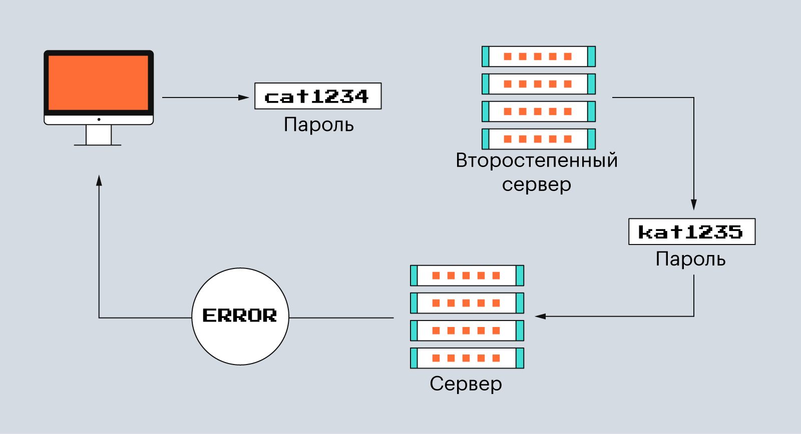
Уровень 2: Канальный
Мы прошли первый уровень. Что же дальше? Если в локальной сети находится более двух устройств, то необходимо определить, куда конкретно направлять информацию. Этим занимается как раз канальный уровень, принимающий на себя важную роль адресации.
Второй уровень принимает биты и трансформирует их в кадры (фреймы). Здесь существуют MAC-адреса (Media Access Control), которые необходимы для идентификации устройств. На втором уровне происходит еще проверка на ошибки, и исправление информации, а также управление ее передачей. Этим занимается LLC (Logical Link Control).
На канальном уровне работают уже более умные железки – коммутаторы. Их задачей является передача кадров от одного устройства другому, используя MAC-адреса.
Уровень 3: Сетевой
На третьем уровне происходит маршрутизация трафика. Этим занимаются такие устройства, как роутеры или маршрутизаторы.
На сетевом уровне работает протокол ARP (Address Resolution Protocol), который определяет соответствие между логическим адресом сетевого уровня (IP) и физическим адресом устройства (MAC). Здесь пересылаемая информация выступает уже в виде пакетов, состоящих из заголовка и поля данных.
Информация об известных IP и MAC-адресах хранится в виде таблицы (ARP-таблица) с данными, что позволяет устройствам не тратить время на повторную идентификацию.
Уровень 4: Транспортный
Четвертый уровень получает пакеты и передает их по сети. Он отвечает за установку соединения, надежность и управление потоком. Блоки данных делятся на отдельные фрагменты, размеры которых зависят от используемого протокола. Главными героями тут выступают 2 протокола TCP (Transmission Control Protocol) и UDP (User Datagram Protocol). В чем их отличие и когда их применять?
При транспортировке данных, наиболее восприимчивых к потерям, например, web-страницы, задействуется протокол TCP с установлением соединения. Он контролирует целостность информации, в данном случае нашей страницы, ибо потеря какого-то контента заставит задуматься пользователя о его полезности. Чтобы сделать передачу более эффективной и быстрой, транспортный уровень разбивает данные на более мелкие сегменты.
UDP-протокол используется с данными, для которых потери не так критичны, например, мультимедиа-трафик. Для них более заметна будет задержка, поэтому UDP обеспечивает связь без установки соединения. Во время передачи данных с помощью протокола UDP, пакеты делятся уже на автономные датаграммы. Они могут доставляться по разным маршрутам и в разной последовательности.
Уровень 5: Сеансовый
Уровни с пятого по седьмой уже работают с чистыми данными. И здесь за дело берутся не сетевые инженеры, а разработчики.
Сеансовый уровень, исходя из названия, отвечает за поддержание сеанса или сессии. Он координирует коммуникацию между приложениями и отвечает за установление, поддержание и завершение связи, синхронизацию задач и сам обмен информацией. Примером для пятого уровня можно назвать созвон в Zoom или прямой эфир на YouTube. Во время сессии необходимо обеспечивать синхронизированную передачу аудио и видео для всех участников, а также поддерживать саму связь. За это как раз отвечают протоколы сеансового уровня (RPC, H.245, RTCP).
Уровень 6: Уровень представления
Шестой уровень подготавливает информацию для последнего и преобразует (сжимает, кодирует, шифрует) их в понятный язык для пользователя или машины. Например, если вы отправляете картинку, то она сначала приходит в виде битов, а потом трансформируются в JPEG, GIF или другой формат.
Уровень 7: Прикладной
Верхний уровень модели OSI – это прикладной. С помощью своих протоколов он отображает данные в понятном конечному пользователю формате. Сюда входят такие технологии, как HTTP, DNS, FTP, SSH и многое другое. Почти каждый человек ежедневно взаимодействует с протоколами прикладного уровня.
Как это все работает?
Чтобы информация могла быть передана по сети от устройства к устройству, данные должны пройти семь кругов, а точнее уровней по модели OSI. Информация передается с уровня 7 вниз на уровень 1 от отправителя, а затем передается с уровня 1 на уровень 7 на устройстве получателя.
Примером передачи данных по модели OSI является приложение электронной почты. Когда пользователь отправляет письмо, оно приходит на уровень представления с использованием определенного протокола (SMTP для исходящей электронной почты). Уровень представления сжимает информацию и отправляет сообщение на сеансовый, который открывает сессию для связи между устройством отправителя и исходящим сервером.
Далее вступает в силу транспортный уровень, где сегментируются полученные данные. Затем сетевой уровень разбивает сегменты на пакеты и отправляет их на канальный уровень, где они разбиваются на фреймы. Фреймы переходят на физический уровень, где информация преобразуется в биты и передается через физическую среду, беспроводные соединения или кабели.
Когда сообщение доходит до получателя, происходит обратный процесс, где информация переходит из битовых единиц и нулей в сообщение на почте получателя. Как-то так.
Что же дальше?
Если кратко разбирать, что произошло дальше, то в 1970-90-х существовало два конкурирующих стандарта: протокол TCP/IP и OSI. Несмотря на годы разработки, серьезные усилия со стороны лидеров отрасли, правительств и ученых, OSI была отвергнута на практике, и TCP/IP стал стандартом де-факто для всего интернет-трафика.
OSI была попыткой отрасли убедить участников согласовать общие сетевые стандарты. В течение периода в конце 1980-х и начале 1990-х инженеры, организации и страны поляризовались по вопросу о том, какой стандарт, модель OSI или TCP/IP сделает компьютерные сети надежными. Однако в то время как OSI разработала свои сетевые стандарты в конце 1980-х, TCP/IP стал широко использоваться для межсетевого взаимодействия. Строгую многоуровневую структуру OSI интернет-защитники считали неэффективной.
Модель OSI все еще используется в качестве эталона, однако протоколы, изначально задуманные для этой модели, не приобрели популярности. Некоторые инженеры утверждают, что эталонная модель по-прежнему актуальна для облачных вычислений. Другие говорят, что исходная модель OSI не соответствует сегодняшним сетевым протоколам, и предлагают вместо этого упрощенный подход.
В статье была описана история появления модели OSI и принцип ее работы. Она подходит для теоретического понимания сетевого стека, поскольку это базовая и обязательная технология для работы с сетями, но ее, на самом деле, не так просто использовать на практике. В настоящее время применяют модель TCP/IP, на которой работает Интернет. Она имеет аналогичную многоуровневую структуру, но не такую сложную, потому что объединяет некоторые уровни OSI.
Если нашли неточности или знаете дополнительные факты об истории OSI, буду рада видеть их в комментариях.
Материалы
Здесь собраны материалы, которые использовались в статье и которые можно почитать/посмотреть, чтобы еще больше углубится в историю:
-
Почитать об отличиях модели SNA и OSI можно в статье «SNA and OSI: Three Strategies for Interconnection» от Мэтью Тилмана (Matthew A. Tillman) и Дэвида Йена (David Chi-Chung Yen).
-
В интервью Джеймса Пелки Чарльз Бакман отвечает на вопросы о модели OSI, рассказывает о собраниях ISO и их участниках.
-
Веб-сайт, созданный на основе книги Джеймса Пелки «The History of Computer Communications». Тут собраны личные рассказы людей, участвовавших в развитии компьютерных коммуникаций.
-
В публикации на Habr представлен перевод статьи «OSI: Интернет, которого не было» Эндрю Л. Рассела. Если вы хотите узнать, как же TCP/IP превзошел OSI, то вам сюда.
-
В видеоинтервью Гарденера Хендри Чарльз Бакман рассказывает про «Проект интегрированных систем 2» General Electric, который был предназначен для создания общей «Производственной информации и системы управления» или MIACS. Этот проект, в свою очередь, создал интегрированное хранилище данных (IDS), первую систему управления базами данных. Здесь он также упоминает и про OSI.
UPD: Citroën 2CV (Deux Chevaux) — это французский автомобиль, а не британский.
#статьи
- 2 сен 2022
-

0
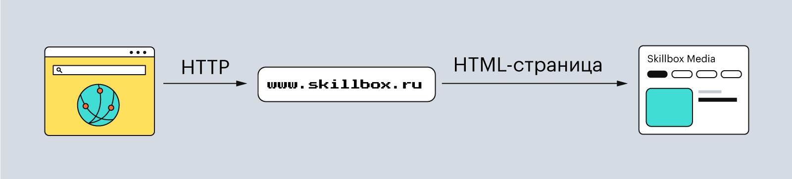
Рассказываем, по каким механизмам работает интернет, как устройства обмениваются данными и почему вы можете сёрфить в соцсетях.
Иллюстрация: Оля Ежак для Skillbox Media

Любитель научной фантастики и технологического прогресса. Хорошо сочетает в себе заумного технаря и утончённого гуманитария. Пишет про IT и радуется этому.
Что происходит, когда вы нажимаете «отправить сообщение» где-нибудь в Telegram? Понятно, что Telegram отправляет это сообщение. Но как это происходит? Куда летят ваши файлы и как они понимают, что нужно лететь именно туда? Разберёмся вместе в этой статье.
Модель OSI (Open System Interconnection) полностью описывает, как работают сетевые устройства. Это набор инструкций (протоколов), которые помогают компьютерам обмениваться данными внутри локальных сетей и всего интернета.
Сама по себе модель OSI — не стандарт интернета, как, например, TCP/IP; её можно сравнить скорее с фреймворками в мире языков программирования: в OSI «из коробки» доступны разные веб-стандарты — UDP, HTTP, FTP, Telnet и другие.
Модель OSI включает семь слоёв, или уровней, — причём каждый из них выполняет определённую функцию: например, передать данные или представить их в понятном для человека виде на компьютере. Кстати, у каждого слоя — свой набор протоколов.
Слои ничего не знают о том, как устроены другие слои. Это называется абстракцией.
Изображение: Skillbox Media
Нижний слой отвечает за физическое представление данных, то есть за то, как данные передаются по проводам или с помощью радиоволн, а самый верхний отвечает за то, как приложения взаимодействуют с сетью.
Нижний слой оперирует такими понятиями, как «тип кабеля» или «тип коннектора», а верхний — такими, как HTTP или API.
Рассмотрим каждый слой подробнее.
На самом нижнем уровне модели OSI данные представляют собой физические объекты — ток, свет или радиоволны. Они передаются по проводам или с помощью беспроводных сигналов.
Этот слой работает с кабелями, контактами в разъёмах, модуляцией сигнала, кодированием единиц и нулей и другими низкоуровневыми штуками. По сути, первый уровень — это уровень проводов и физических способов передачи сигнала. Минимальная абстракция.
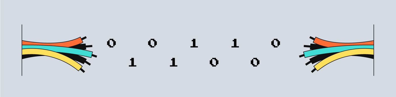
Изображение: Skillbox Media
Самый известный протокол на физическом уровне — Ethernet. Он описывает, как сигналы кодируются и передаются по проводам. Кроме него, есть Bluetooth, Wi-Fi и ИК-порт, которые также содержат инструкции для передачи данных.
Устройства физического уровня — концентраторы и репитеры. Они не вникают в логику сигнала: получили данные — передали их дальше по проводу.
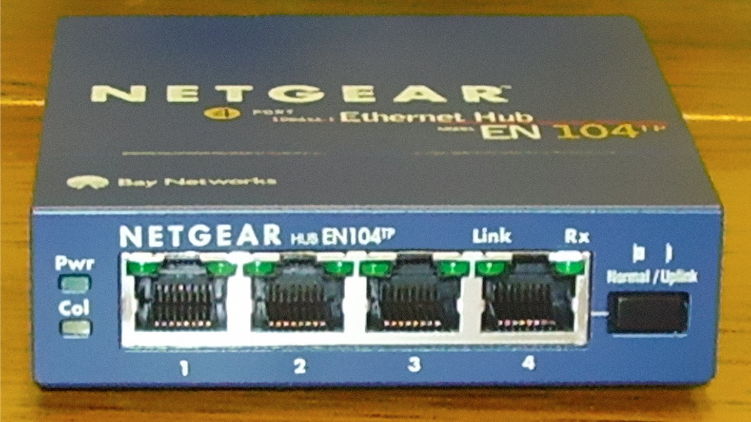
Фото: Wikimedia Commons
Над физическим уровнем располагается канальный. Его задача — проверить целостность полученных данных и исправить ошибки. Этот уровень «поумнее» предыдущего: он уже понимает, что разные амплитуды напряжений отвечают разным битам — нулям и единицам. А ещё канальный уровень умеет кодировать сигналы в биты и передавать их дальше.
Полученные с нижнего уровня данные делятся на фреймы, или кадры. Каждый фрейм состоит из служебной информации — например, адреса отправителя и адреса получателя, — а также самих данных.
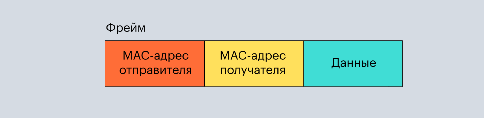
Изображение: Skillbox Media
Получается что-то вроде почтового конверта. На лицевой стороне у него написано, от кого пришло письмо, а внутри находится само письмо (в нашем случае данные).
Лицевая сторона конверта — это MAC-адрес устройства, которое отправило нам информацию. Он нужен, чтобы идентифицировать устройства в одной сети, состоит из 48 или 64 бит и выглядит примерно так:

Изображение: Skillbox Media
Ещё один важный факт о MAC-адресах: когда на заводе собирают ноутбук или смартфон, ему сразу же присваивают определённый MAC-адрес, который потом уже никак нельзя поменять. MAC-адрес настольных ПК зашит в сетевую карту, поэтому его можно изменить, только заменив эту самую карту.
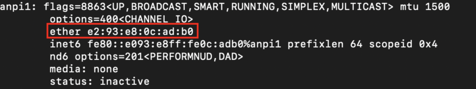
С помощью команды ifconfig можно узнать MAC-адрес вашего Macbook или компьютера на Linux. В Windows нужно ввести команду ipconfig.
Канальный уровень не так прост — он делится ещё на два подуровня:
- уровень управления логическим каналом — LLC (Logical Link Control);
- уровень управления доступом к среде — тот самый MAC (Media Access Control).
Первый подуровень нужен для взаимодействия с верхним уровнем, сетевым, а второй — для взаимодействия с нижним, физическим.
Устройства канального уровня — коммутаторы и мосты. Они нужны, чтобы передавать фреймы нужному адресату. Протоколы канального уровня — PPP, CDP.
Этот уровень отвечает за маршрутизацию данных внутри сети между компьютерами. Здесь уже появляются такие термины, как «маршрутизаторы» и «IP-адреса».
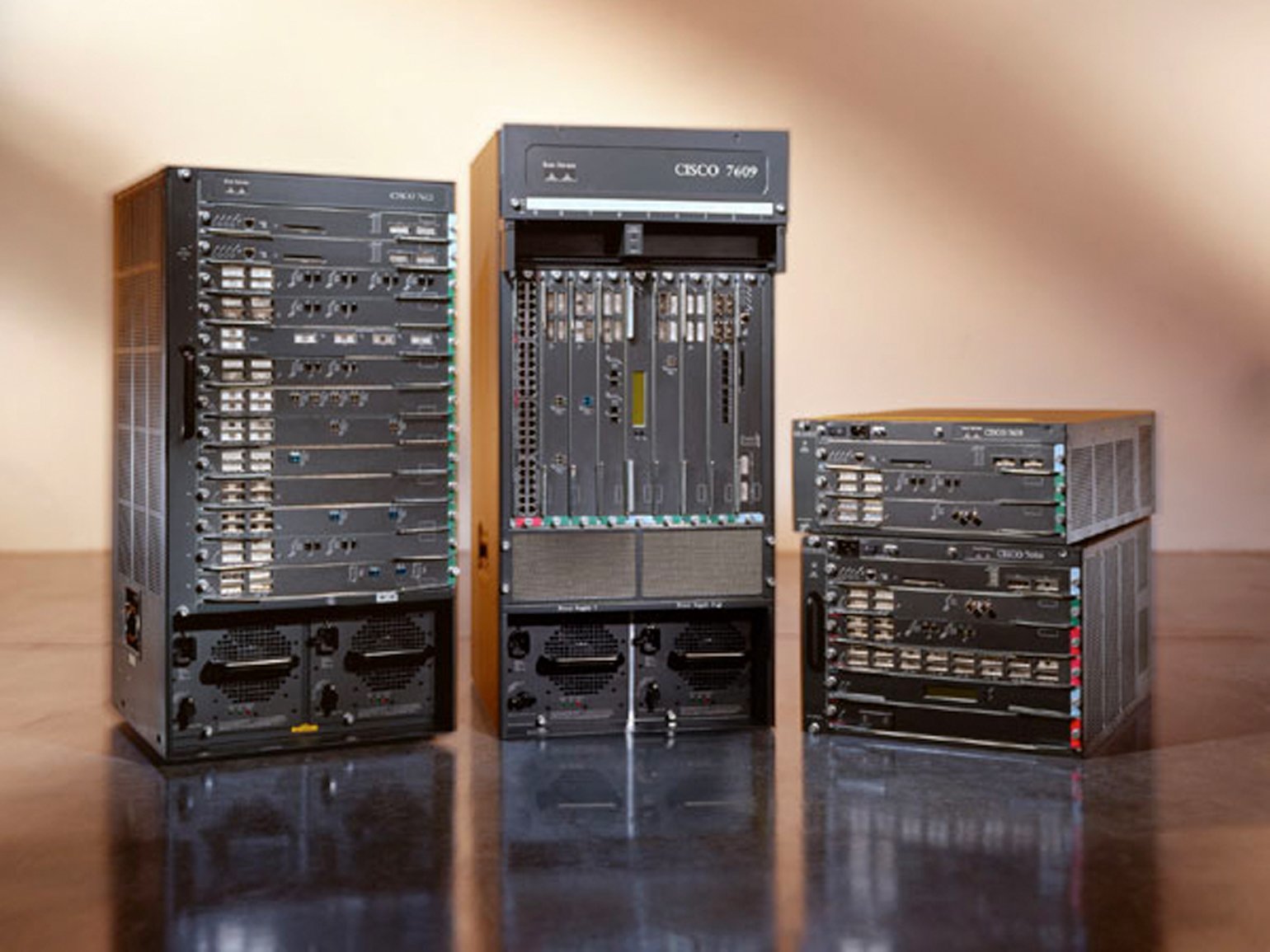
Фото: Wikimedia Commons
Маршрутизаторы позволяют разным сетям общаться друг с другом: они используют MAC-адреса, чтобы построить путь от одного устройства к другому.
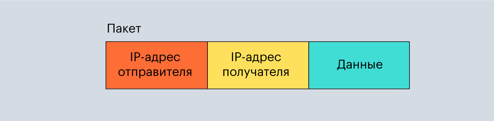
Данные на сетевом уровне представляются в виде пакетов. Такие пакеты похожи на фреймы из канального уровня, но используют другие адреса получателя и отправителя — IP-адреса.
Чтобы получить IP-адрес обоих устройств (отправителя и получателя), используется протокол ARP (Address Resolution Protocol). Он умеет конвертировать MAC- в IP-адрес и наоборот.
Из названия понятно, что на этом уровне происходит передача данных по сети. Так и есть. Два главных протокола здесь — TCP и UDP. Они как раз и отвечают за то, как именно будут передаваться данные.
TCP (Transmission Control Protocol) — это протокол, который гарантирует доставку данных в корректном виде. Он жёстко следит за каждым битом информации, но работает гораздо медленнее UDP.
Например, когда вы вводите логин и пароль при входе в социальную сеть, очень важно, чтобы все символы отправились в определённой последовательности. Если какие-то потеряются или изменятся, вы просто не сможете авторизоваться. Поэтому протокол TCP использует разные методы проверок — например, контрольные суммы.
Изображение: Skillbox Media
А вот в видео или аудио небольшие потери некритичны, зато важна скорость передачи данных. Для таких задач как раз и придумали протокол UDP (User Datagram Protocol). Он уже не проверяет цельность битов, его задача — как можно быстрее передать данные с одного устройства на другое.
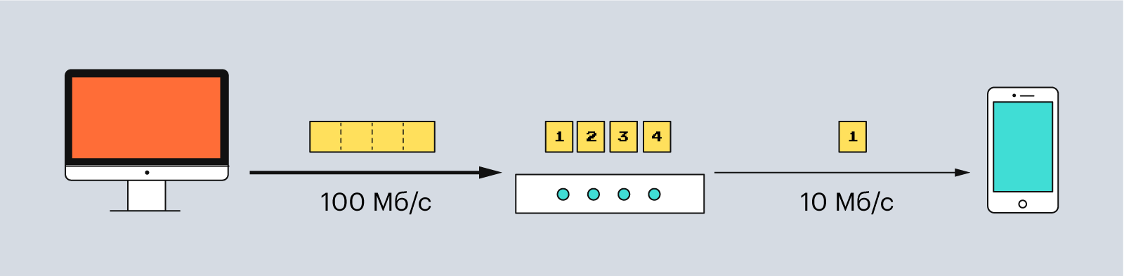
В протоколе TCP данные делятся на сегменты. Каждый сегмент — часть пакета. Сегменты нужны, чтобы передавать информацию по сети, учитывая её пропускную способность.
Например, если вы передаёте данные с компьютера, у которого пропускная способность 100 Мб/c, на смартфон с пропускной способность 10 Мб/c, то данные разделятся так, чтобы не застревать в самом медленном устройстве.
Изображение: Skillbox Media
Ещё сегментация важна для надёжности. Один большой пакет может быть потерян или направлен не тому адресату. А маленькие пакеты снижают риск подобных ошибок и даже позволяют проверять их количество. Если какой-то сегмент не получилось доставить, протокол TCP может запросить его у отправителя снова. Так обеспечивается надёжность.
В UDP данные делятся на датаграммы — это примерно то же, что и пакет, только датаграммы автономны. Каждая датаграмма содержит всё необходимое, чтобы дойти до получателя. Поэтому они не зависят от сети и могут доставляться разными маршрутами и в произвольном порядке.
Начиная с этого уровня и выше, данные имеют уже нормальный вид — например, привычных нам JPEG- или MP3-файлов. Задача сети на этих уровнях — представить информацию в понятном для человека виде и сделать так, чтобы пользователь мог её как-то «потрогать».
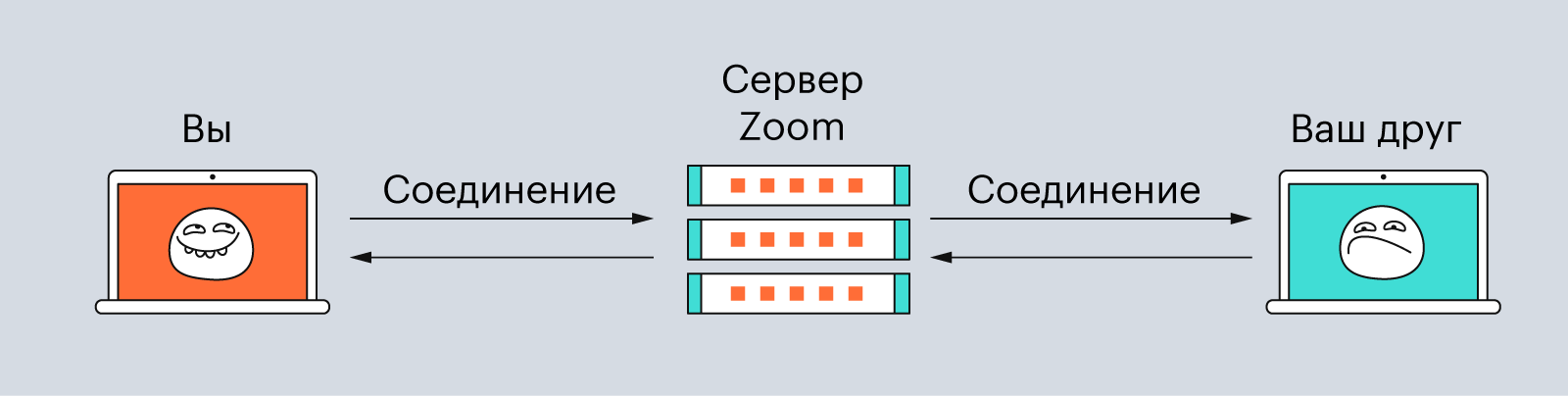
Сеансовый уровень управляет соединениями, или сессиями. Типичный пример — звонок по Skype или Zoom. Когда вы звоните другому человеку, между вашими компьютерами устанавливается соединение, по которому передаётся аудио и видео. Если такое соединение разорвать, то и ваш звонок прервётся.
На сеансовом уровне очень важно, чтобы соединение правильно установилось и поддерживалось. То есть механизмы протоколов должны проверить, что у обоих собеседников есть нужные кодеки и сигнал между устройствами присутствует.
Изображение: Skillbox Media
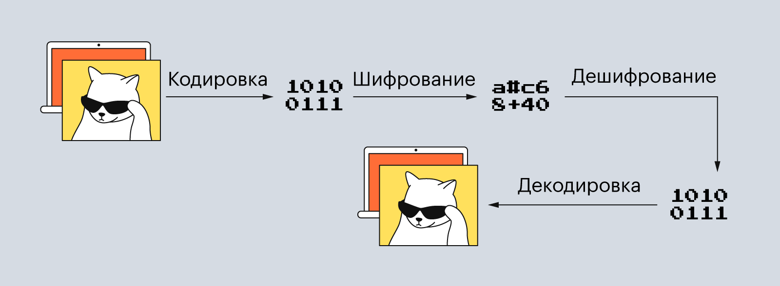
На этом уровне происходит преобразование форматов данных — их кодирование и сжатие. Например, полученные данные могут превратиться в GIF- или MP4-файл. То же самое происходит и в обратном порядке: когда пользователь отправляет файл другому человеку, данные сначала конвертируются в биты и сжимаются, а потом уже передаются на транспортный уровень.
Помимо кодировки и сжатия на уровне представления, данные могут шифроваться — если, конечно, это необходимо.
Изображение: Skillbox Media
Последний уровень модели OSI — прикладной. На нём находятся сетевые службы, которые помогают без проблем сёрфить в интернете.
Прикладной уровень похож на некий графический интерфейс для всей модели OSI — с его помощью пользователь взаимодействует с другими уровнями, даже не подозревая об этом. Этот интерфейс называется сетевым.
Самые популярные из сетевых интерфейсов — это HTTP, HTTPS, FTP и SMTP. А «устройства» здесь — это уже программы: Zoom, Telegram, браузеры.
Изображение: Skillbox Media
Модель OSI описывает, как работает весь интернет: как электрические сигналы преобразуются в картинки с котиками и как устройства обмениваются этими данными.
Модель включает семь уровней:
- физический;
- канальный;
- сетевой;
- транспортный;
- сеансный;
- представления;
- прикладной.
На каждом уровне находятся определённые протоколы, которые помогают данным перемещаться или превращаться в удобный для пользователей формат.

Учись бесплатно:
вебинары по программированию, маркетингу и дизайну.
Участвовать
Школа дронов для всех
Учим программировать беспилотники и управлять ими.
Узнать больше
The Open Systems Interconnection model (OSI model) is a conceptual model that ‘provides a common basis for the coordination of [ISO] standards development for the purpose of systems interconnection’.[2] In the OSI reference model, the communications between a computing system are split into seven different abstraction layers: Physical, Data Link, Network, Transport, Session, Presentation, and Application.[3]
The model partitions the flow of data in a communication system into seven abstraction layers to describe networked communication from the physical implementation of transmitting bits across a communications medium to the highest-level representation of data of a distributed application. Each intermediate layer serves a class of functionality to the layer above it and is served by the layer below it. Classes of functionality are realized in all software development through all and any standardized communication protocols.
Each layer in the OSI model has its own well-defined functions, and the functions of each layer communicate and interact with the layers immediately above and below it, unless the layer does not have layers below or above.
The Internet protocol suite has a separate model, the layers of which are mentioned in RFC 1122 and RFC 1123. That model combines the physical and data link layers of the OSI model into a single link layer, and has a single application layer for all protocols above the transport layer, as opposed to the separate application, presentation and session layers of the OSI model.
In comparison, several networking models have sought to create an intellectual framework for clarifying networking concepts and activities,[citation needed] but none have been as successful as the OSI reference model in becoming the standard model for discussing, teaching, and learning for the networking procedures in the field of Information technology. Additionally, the model allows transparent communication through equivalent exchange of protocol data units (PDUs) between two parties, through what is known as peer-to-peer networking (also known as peer-to-peer communication). As a result, the OSI reference model has not only become an important piece among professionals and non-professionals alike, but also in all networking between one or many parties, due in large part to its commonly accepted user-friendly framework.[4]
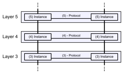
Communication in the OSI-Model (example with layers 3 to 5)
History[edit]
The development of the OSI model started in the late 1970s to support the emergence of the diverse computer networking methods that were competing for application in the large national networking efforts in the world (see Protocol Wars). In the 1980s, the model became a working product of the Open Systems Interconnection group at the International Organization for Standardization (ISO). While attempting to provide a comprehensive description of networking, the model failed to garner reliance during the design of the Internet, which is reflected in the less prescriptive Internet Protocol Suite, principally sponsored under the auspices of the Internet Engineering Task Force (IETF).
In the early- and mid-1970s, networking was largely either government-sponsored (NPL network in the UK, ARPANET in the US, CYCLADES in France) or vendor-developed with proprietary standards, such as IBM’s Systems Network Architecture and Digital Equipment Corporation’s DECnet. Public data networks were only just beginning to emerge, and these began to use the X.25 standard in the late 1970s.[5][6]
The Experimental Packet Switched System in the UK circa 1973–1975 identified the need for defining higher level protocols.[5] The UK National Computing Centre publication ‘Why Distributed Computing’ which came from considerable research into future configurations for computer systems,[7] resulted in the UK presenting the case for an international standards committee to cover this area at the ISO meeting in Sydney in March 1977.[8][9]
Beginning in 1977, the ISO initiated a program to develop general standards and methods of networking. A similar process evolved at the International Telegraph and Telephone Consultative Committee (CCITT, from French: Comité Consultatif International Téléphonique et Télégraphique). Both bodies developed documents that defined similar networking models. The British Department of Trade and Industry acted as the secretariat and universities in the United Kingdom developed prototypes of the standards.[10]
The OSI model was first defined in raw form in Washington, DC, in February 1978 by Hubert Zimmermann of France and the refined but still draft standard was published by the ISO in 1980.[11]
The drafters of the reference model had to contend with many competing priorities and interests. The rate of technological change made it necessary to define standards that new systems could converge to rather than standardizing procedures after the fact; the reverse of the traditional approach to developing standards.[12] Although not a standard itself, it was a framework in which future standards could be defined.[13]
In 1983, the CCITT and ISO documents were merged to form The Basic Reference Model for Open Systems Interconnection, usually referred to as the Open Systems Interconnection Reference Model, OSI Reference Model, or simply OSI model. It was published in 1984 by both the ISO, as standard ISO 7498, and the renamed CCITT (now called the Telecommunications Standardization Sector of the International Telecommunication Union or ITU-T) as standard X.200.
OSI had two major components, an abstract model of networking, called the Basic Reference Model or seven-layer model, and a set of specific protocols. The OSI reference model was a major advance in the standardisation of network concepts. It promoted the idea of a consistent model of protocol layers, defining interoperability between network devices and software.
The concept of a seven-layer model was provided by the work of Charles Bachman at Honeywell Information Systems.[14] Various aspects of OSI design evolved from experiences with the NPL network, ARPANET, CYCLADES, EIN, and the International Networking Working Group (IFIP WG6.1). In this model, a networking system was divided into layers. Within each layer, one or more entities implement its functionality. Each entity interacted directly only with the layer immediately beneath it and provided facilities for use by the layer above it.
The OSI standards documents are available from the ITU-T as the X.200-series of recommendations.[15] Some of the protocol specifications were also available as part of the ITU-T X series. The equivalent ISO/IEC standards for the OSI model were available from ISO. Not all are free of charge.[16]
OSI was an industry effort, attempting to get industry participants to agree on common network standards to provide multi-vendor interoperability.[17] It was common for large networks to support multiple network protocol suites, with many devices unable to interoperate with other devices because of a lack of common protocols. For a period in the late 1980s and early 1990s, engineers, organizations and nations became polarized over the issue of which standard, the OSI model or the Internet protocol suite, would result in the best and most robust computer networks.[9][18][19] However, while OSI developed its networking standards in the late 1980s,[20][21] TCP/IP came into widespread use on multi-vendor networks for internetworking.
The OSI model is still used as a reference for teaching and documentation;[22] however, the OSI protocols originally conceived for the model did not gain popularity. Some engineers argue the OSI reference model is still relevant to cloud computing.[23] Others say the original OSI model doesn’t fit today’s networking protocols and have suggested instead a simplified approach.[24][25]
Definitions[edit]
Communication protocols enable an entity in one host to interact with a corresponding entity at the same layer in another host. Service definitions, like the OSI Model, abstractly describe the functionality provided to an (N)-layer by an (N-1) layer, where N is one of the seven layers of protocols operating in the local host.
At each level N, two entities at the communicating devices (layer N peers) exchange protocol data units (PDUs) by means of a layer N protocol. Each PDU contains a payload, called the service data unit (SDU), along with protocol-related headers or footers.
Data processing by two communicating OSI-compatible devices proceeds as follows:
- The data to be transmitted is composed at the topmost layer of the transmitting device (layer N) into a protocol data unit (PDU).
- The PDU is passed to layer N-1, where it is known as the service data unit (SDU).
- At layer N-1 the SDU is concatenated with a header, a footer, or both, producing a layer N-1 PDU. It is then passed to layer N-2.
- The process continues until reaching the lowermost level, from which the data is transmitted to the receiving device.
- At the receiving device the data is passed from the lowest to the highest layer as a series of SDUs while being successively stripped from each layer’s header or footer until reaching the topmost layer, where the last of the data is consumed.
Standards documents[edit]
The OSI model was defined in ISO/IEC 7498 which consists of the following parts:
- ISO/IEC 7498-1 The Basic Model
- ISO/IEC 7498-2 Security Architecture
- ISO/IEC 7498-3 Naming and addressing
- ISO/IEC 7498-4 Management framework
ISO/IEC 7498-1 is also published as ITU-T Recommendation X.200.
Layer architecture[edit]
The recommendation X.200 describes seven layers, labelled 1 to 7. Layer 1 is the lowest layer in this model.
| Layer | Protocol data unit (PDU) | Function[26] | ||
|---|---|---|---|---|
| Host layers |
7 | Application | Data | High-level protocols such as for resource sharing or remote file access, e.g. HTTP. |
| 6 | Presentation | Translation of data between a networking service and an application; including character encoding, data compression and encryption/decryption | ||
| 5 | Session | Managing communication sessions, i.e., continuous exchange of information in the form of multiple back-and-forth transmissions between two nodes | ||
| 4 | Transport | Segment, Datagram | Reliable transmission of data segments between points on a network, including segmentation, acknowledgement and multiplexing | |
| Media layers |
3 | Network | Packet | Structuring and managing a multi-node network, including addressing, routing and traffic control |
| 2 | Data link | Frame | Transmission of data frames between two nodes connected by a physical layer | |
| 1 | Physical | Bit, Symbol | Transmission and reception of raw bit streams over a physical medium |
Layer 1: Physical layer[edit]
The Physical Layer is responsible for the transmission and reception of unstructured raw data between a device, such as a network interface controller, Ethernet hub, or network switch, and a physical transmission medium. It converts the digital bits into electrical, radio, or optical signals. Layer specifications define characteristics such as voltage levels, the timing of voltage changes, physical data rates, maximum transmission distances, modulation scheme, channel access method and physical connectors. This includes the layout of pins, voltages, line impedance, cable specifications, signal timing and frequency for wireless devices. Bit rate control is done at the physical layer and may define transmission mode as simplex, half duplex, and full duplex. The components of a physical layer can be described in terms of a network topology. Physical layer specifications are included in the specifications for the ubiquitous Bluetooth, Ethernet, and USB standards. An example of a less well-known physical layer specification would be for the CAN standard.
The Physical Layer also specifies how encoding occurs over a physical signal, such as electrical voltage or a light pulse. For example, a 1 bit might be represented on a copper wire by the transition from a 0-volt to a 5-volt signal, whereas a 0 bit might be represented by the transition from a 5-volt signal to 0-volt signal. As a result, common problems occurring at the Physical Layer are often related to the incorrect media termination, EMI or noise scrambling, and NICs and hubs that are misconfigured or do not work correctly.
Layer 2: Data link layer[edit]
The data link layer provides node-to-node data transfer—a link between two directly connected nodes. It detects and possibly corrects errors that may occur in the physical layer.
It defines the protocol to establish and terminate a connection between two physically connected devices. It also defines the protocol for flow control between them.
IEEE 802 divides the data link layer into two sublayers:[27]
- Medium access control (MAC) layer – responsible for controlling how devices in a network gain access to a medium and permission to transmit data.
- Logical link control (LLC) layer – responsible for identifying and encapsulating network layer protocols, and controls error checking and frame synchronization.
The MAC and LLC layers of IEEE 802 networks such as 802.3 Ethernet, 802.11 Wi-Fi, and 802.15.4 Zigbee operate at the data link layer.
The Point-to-Point Protocol (PPP) is a data link layer protocol that can operate over several different physical layers, such as synchronous and asynchronous serial lines.
The ITU-T G.hn standard, which provides high-speed local area networking over existing wires (power lines, phone lines and coaxial cables), includes a complete data link layer that provides both error correction and flow control by means of a selective-repeat sliding-window protocol.
Security, specifically (authenticated) encryption, at this layer can be applied with MACSec.
Layer 3: Network layer[edit]
The network layer provides the functional and procedural means of transferring packets from one node to another connected in «different networks». A network is a medium to which many nodes can be connected, on which every node has an address and which permits nodes connected to it to transfer messages to other nodes connected to it by merely providing the content of a message and the address of the destination node and letting the network find the way to deliver the message to the destination node, possibly routing it through intermediate nodes. If the message is too large to be transmitted from one node to another on the data link layer between those nodes, the network may implement message delivery by splitting the message into several fragments at one node, sending the fragments independently, and reassembling the fragments at another node. It may, but does not need to, report delivery errors.
Message delivery at the network layer is not necessarily guaranteed to be reliable; a network layer protocol may provide reliable message delivery, but it need not do so.
A number of layer-management protocols, a function defined in the management annex, ISO 7498/4, belong to the network layer. These include routing protocols, multicast group management, network-layer information and error, and network-layer address assignment. It is the function of the payload that makes these belong to the network layer, not the protocol that carries them.[28]
Layer 4: Transport layer[edit]
The transport layer provides the functional and procedural means of transferring variable-length data sequences from a source host to a destination host from one application to another across a network, while maintaining the quality-of-service functions. Transport protocols may be connection-oriented or connectionless.
This may require breaking large protocol data units or long data streams into smaller chunks called «segments», since the network layer imposes a maximum packet size called the maximum transmission unit (MTU), which depends on the maximum packet size imposed by all data link layers on the network path between the two hosts. The amount of data in a data segment must be small enough to allow for a network-layer header and a transport-layer header. For example, for data being transferred across Ethernet, the MTU is 1500 bytes, the minimum size of a TCP header is 20 bytes, and the minimum size of an IPv4 header is 20 bytes, so the maximum segment size is 1500-(20+20) bytes, or 1460 bytes. The process of dividing data into segments is called segmentation; it is an optional function of the transport layer. Some connection-oriented transport protocols, such as TCP and the OSI connection-oriented transport protocol (COTP), perform segmentation and reassembly of segments on the receiving side; connectionless transport protocols, such as UDP and the OSI connectionless transport protocol (CLTP), usually do not.
The transport layer also controls the reliability of a given link between a source and destination host through flow control, error control, and acknowledgments of sequence and existence. Some protocols are state- and connection-oriented. This means that the transport layer can keep track of the segments and retransmit those that fail delivery through the acknowledgment hand-shake system. The transport layer will also provide the acknowledgement of the successful data transmission and sends the next data if no errors occurred.
Reliability, however, is not a strict requirement within the transport layer. Protocols like UDP, for example, are used in applications that are willing to accept some packet loss, reordering, errors or duplication. Streaming media, real-time multiplayer games and voice over IP (VoIP) are examples of applications in which loss of packets is not usually a fatal problem.
The OSI connection-oriented transport protocol defines five classes of connection-mode transport protocols ranging from class 0 (which is also known as TP0 and provides the fewest features) to class 4 (TP4, designed for less reliable networks, similar to the Internet). Class 0 contains no error recovery and was designed for use on network layers that provide error-free connections. Class 4 is closest to TCP, although TCP contains functions, such as the graceful close, which OSI assigns to the session layer. Also, all OSI TP connection-mode protocol classes provide expedited data and preservation of record boundaries. Detailed characteristics of TP0-4 classes are shown in the following table:[29]
| Feature name | TP0 | TP1 | TP2 | TP3 | TP4 |
|---|---|---|---|---|---|
| Connection-oriented network | Yes | Yes | Yes | Yes | Yes |
| Connectionless network | No | No | No | No | Yes |
| Concatenation and separation | No | Yes | Yes | Yes | Yes |
| Segmentation and reassembly | Yes | Yes | Yes | Yes | Yes |
| Error recovery | No | Yes | Yes | Yes | Yes |
| Reinitiate connectiona | No | Yes | No | Yes | No |
| Multiplexing / demultiplexing over single virtual circuit | No | No | Yes | Yes | Yes |
| Explicit flow control | No | No | Yes | Yes | Yes |
| Retransmission on timeout | No | No | No | No | Yes |
| Reliable transport service | No | Yes | No | Yes | Yes |
| a If an excessive number of PDUs are unacknowledged. |
An easy way to visualize the transport layer is to compare it with a post office, which deals with the dispatch and classification of mail and parcels sent. A post office inspects only the outer envelope of mail to determine its delivery. Higher layers may have the equivalent of double envelopes, such as cryptographic presentation services that can be read by the addressee only. Roughly speaking, tunnelling protocols operate at the transport layer, such as carrying non-IP protocols such as IBM’s SNA or Novell’s IPX over an IP network, or end-to-end encryption with IPsec. While Generic Routing Encapsulation (GRE) might seem to be a network-layer protocol, if the encapsulation of the payload takes place only at the endpoint, GRE becomes closer to a transport protocol that uses IP headers but contains complete Layer 2 frames or Layer 3 packets to deliver to the endpoint. L2TP carries PPP frames inside transport segments.
Although not developed under the OSI Reference Model and not strictly conforming to the OSI definition of the transport layer, the Transmission Control Protocol (TCP) and the User Datagram Protocol (UDP) of the Internet Protocol Suite are commonly categorized as layer-4 protocols within OSI.
Transport Layer Security (TLS) does not strictly fit inside the model either. It contains characteristics of the transport and presentation layers.[30][31]
Layer 5: Session layer[edit]
The Session Layer creates the setup, controls the connections, and ends the teardown, between two or more computers, which is called a «session». Since DNS and other Name Resolution Protocols operate in this part of the layer, common functions of the Session Layer include user logon (establishment), name lookup (management), and user logoff (termination) functions. Including this matter, authentication protocols are also built into most client software, such as FTP Client and NFS Client for Microsoft Networks. Therefore, the Session layer establishes, manages and terminates the connections between the local and remote application. The Session Layer also provides for full-duplex, half-duplex, or simplex operation, and establishes procedures for checkpointing, suspending, restarting, and terminating a session between two related streams of data, such as an audio and a video stream in a web-conferencing application. Therefore, the session layer is commonly implemented explicitly in application environments that use remote procedure calls.
Layer 6: Presentation layer[edit]
The Presentation Layer establishes data formatting and data translation into a format specified by the application layer during the encapsulation of outgoing messages while being passed down the protocol stack, and possibly reversed during the deencapsulation of incoming messages when being passed up the protocol stack. For this very reason, outgoing messages during encapsulation are converted into a format specified by the application layer, while the conversation for incoming messages during deencapsulation are reversed.
The Presentation Layer handles protocol conversion, data encryption, data decryption, data compression, data decompression, incompatibility of data representation between OSs, and graphic commands. The presentation layer transforms data into the form that the application layer accepts, to be sent across a network. Since the presentation layer converts data and graphics into a display format for the Application Layer, the Presentation Layer is sometimes called the syntax layer.[32] For this reason, the Presentation Layer negotiates the transfer of syntax structure through the Basic Encoding Rules of Abstract Syntax Notation One (ASN.1), with capabilities such as converting an EBCDIC-coded text file to an ASCII-coded file, or serialization of objects and other data structures from and to XML.[4]
Layer 7: Application layer[edit]
The application layer is the layer of the OSI model that is closest to the end user, which means both the OSI Application Layer and the user interact directly with software application that implements a component of communication between the client and server, such as File Explorer and Microsoft Word. Such application programs fall outside the scope of the OSI model unless they are directly integrated into the Application layer through the functions of communication, as is the case with applications such as Web Browsers and Email Programs. Other examples of software are Microsoft Network Software for File and Printer Sharing and Unix/Linux Network File System Client for access to shared file resources.
Application-layer functions typically include file sharing, message handling, and database access, through the most common protocols at the application layer, known as HTTP, FTP, SMB/CIFS, TFTP, and SMTP. When identifying communication partners, the application layer determines the identity and availability of communication partners for an application with data to transmit. The most important distinction in the application layer is the distinction between the application-entity and the application. For example, a reservation website might have two application-entities: one using HTTP to communicate with its users, and one for a remote database protocol to record reservations. Neither of these protocols have anything to do with reservations. That logic is in the application itself. The application layer has no means to determine the availability of resources in the network.[4]
Cross-layer functions[edit]
Cross-layer functions are services that are not tied to a given layer, but may affect more than one layer.[33] Some orthogonal aspects, such as management and security, involve all of the layers (See ITU-T X.800 Recommendation[34]). These services are aimed at improving the CIA triad—confidentiality, integrity, and availability—of the transmitted data.
Cross-layer functions are the norm, in practice, because the availability of a communication service is determined by the interaction between network design and network management protocols.
Specific examples of cross-layer functions include the following:
- Security service (telecommunication)[34] as defined by ITU-T X.800 recommendation.
- Management functions, i.e. functions that permit to configure, instantiate, monitor, terminate the communications of two or more entities: there is a specific application-layer protocol, Common Management Information Protocol (CMIP) and its corresponding service, Common Management Information Service (CMIS), they need to interact with every layer in order to deal with their instances.
- Multiprotocol Label Switching (MPLS), ATM, and X.25 are 3a protocols. OSI subdivides the Network Layer into three sublayers: 3a) Subnetwork Access, 3b) Subnetwork Dependent Convergence and 3c) Subnetwork Independent Convergence.[35] It was designed to provide a unified data-carrying service for both circuit-based clients and packet-switching clients which provide a datagram-based service model. It can be used to carry many different kinds of traffic, including IP packets, as well as native ATM, SONET, and Ethernet frames. Sometimes one sees reference to a Layer 2.5.
- Cross MAC and PHY Scheduling is essential in wireless networks because of the time-varying nature of wireless channels. By scheduling packet transmission only in favourable channel conditions, which requires the MAC layer to obtain channel state information from the PHY layer, network throughput can be significantly improved and energy waste can be avoided.[36]
Programming interfaces[edit]
Neither the OSI Reference Model, nor any OSI protocol specifications, outline any programming interfaces, other than deliberately abstract service descriptions. Protocol specifications define a methodology for communication between peers, but the software interfaces are implementation-specific.
For example, the Network Driver Interface Specification (NDIS) and Open Data-Link Interface (ODI) are interfaces between the media (layer 2) and the network protocol (layer 3).
Comparison to other networking suites[edit]
The table below presents a list of OSI layers, the original OSI protocols, and some approximate modern matches. It is very important to note that this correspondence is rough: the OSI model contains idiosyncrasies not found in later systems such as the IP stack in modern Internet.[25]
| Layer | OSI protocols | TCP/IP protocols | Signaling System 7[37] |
AppleTalk | IPX | SNA | UMTS | Miscellaneous examples | |
|---|---|---|---|---|---|---|---|---|---|
| No. | Name | ||||||||
| 7 | Application |
|
|
|
|
|
|
|
|
| 6 | Presentation |
|
|
|
|
||||
| 5 | Session |
|
Sockets (session establishment in TCP / RTP / PPTP) |
|
|
|
|
||
| 4 | Transport |
|
|
|
|
|
|||
| 3 | Network |
|
|
|
ATP (TokenTalk / EtherTalk) |
|
|
|
|
| 2 | Data link |
|
|
|
|
IEEE 802.3 framing Ethernet II framing |
|
|
|
| 1 | Physical |
|
TCP/IP stack does not care about the physical medium, as long as it provides a way to communicate octets |
|
|
|
UMTS air interfaces |
|
Comparison with TCP/IP model[edit]
The design of protocols in the TCP/IP model of the Internet does not concern itself with strict hierarchical encapsulation and layering. RFC 3439 contains a section entitled «Layering considered harmful».[42] TCP/IP does recognize four broad layers of functionality which are derived from the operating scope of their contained protocols: the scope of the software application; the host-to-host transport path; the internetworking range; and the scope of the direct links to other nodes on the local network.[43]
Despite using a different concept for layering than the OSI model, these layers are often compared with the OSI layering scheme in the following manner:
- The Internet application layer maps to the OSI application layer, presentation layer, and most of the session layer.
- The TCP/IP transport layer maps to the graceful close function of the OSI session layer as well as the OSI transport layer.
- The internet layer performs functions as those in a subset of the OSI network layer.
- The link layer corresponds to the OSI data link layer and may include similar functions as the physical layer, as well as some protocols of the OSI’s network layer.
These comparisons are based on the original seven-layer protocol model as defined in ISO 7498, rather than refinements in the internal organization of the network layer.
The OSI protocol suite that was specified as part of the OSI project was considered by many as too complicated and inefficient, and to a large extent unimplementable.[44] Taking the «forklift upgrade» approach to networking, it specified eliminating all existing networking protocols and replacing them at all layers of the stack. This made implementation difficult and was resisted by many vendors and users with significant investments in other network technologies. In addition, the protocols included so many optional features that many vendors’ implementations were not interoperable.[44]
Although the OSI model is often still referenced, the Internet protocol suite has become the standard for networking. TCP/IP’s pragmatic approach to computer networking and to independent implementations of simplified protocols made it a practical methodology.[44] Some protocols and specifications in the OSI stack remain in use, one example being IS-IS, which was specified for OSI as ISO/IEC 10589:2002 and adapted for Internet use with TCP/IP as RFC 1142.
See also[edit]
- Government Open Systems Interconnection Profile
- Hierarchical internetworking model
- History of the Internet
- Layer 8
- List of information technology initialisms
- Management plane
- Recursive Internetwork Architecture
- Service layer
- Session multiplexing
Further reading[edit]
- John Day, «Patterns in Network Architecture: A Return to Fundamentals» (Prentice Hall 2007, ISBN 978-0-13-225242-3)
- Marshall Rose, «The Open Book» (Prentice-Hall, Englewood Cliffs, 1990)
- David M. Piscitello, A. Lyman Chapin, Open Systems Networking (Addison-Wesley, Reading, 1993)
- Andrew S. Tanenbaum, Computer Networks, 4th Edition, (Prentice-Hall, 2002) ISBN 0-13-066102-3
- Gary Dickson; Alan Lloyd (July 1992). Open Systems Interconnection/Computer Communications Standards and Gossip Explained. Prentice-Hall. ISBN 978-0136401117.
- Russell, Andrew L. (2014). Open Standards and the Digital Age: History, Ideology, and Networks. Cambridge University Press. ISBN 978-1-139-91661-5.
References[edit]
- ^ «X.225 : Information technology – Open Systems Interconnection – Connection-oriented Session protocol: Protocol specification». Archived from the original on 1 February 2021. Retrieved 24 November 2021.
- ^ ISO/IEC 7498-1:1994 Information technology — Open Systems Interconnection — Basic Reference Model: The Basic Model. June 1999. Introduction. Retrieved 26 August 2022.
- ^ «What is the OSI Model?». Forcepoint. 10 August 2018. Retrieved 20 May 2022.
- ^ a b c Tomsho, Greg (2016). Guide to Networking Essentials (7th ed.). Cengage. Retrieved 3 April 2022.
- ^ a b Davies, Howard; Bressan, Beatrice (26 April 2010). A History of International Research Networking: The People who Made it Happen. John Wiley & Sons. pp. 2–3. ISBN 978-3-527-32710-2.
- ^ Roberts, Dr. Lawrence G. (November 1978). «The Evolution of Packet Switching» (PDF). IEEE Invited Paper. Retrieved 26 February 2022.
- ^ Down, Peter John; Taylor, Frank Edward (1976). Why distributed computing?: An NCC review of potential and experience in the UK. NCC Publications. ISBN 9780850121704.
- ^ Radu, Roxana (2019). «Revisiting the Origins: The Internet and its Early Governance». Negotiating Internet Governance. Oxford University Press. doi:10.1093/oso/9780198833079.003.0003. ISBN 9780191871405.
- ^ a b Andrew L. Russell (30 July 2013). «OSI: The Internet That Wasn’t». IEEE Spectrum. Vol. 50, no. 8.
- ^ Campbell-Kelly, Martin; Garcia-Swartz, Daniel D (2013). «The History of the Internet: The Missing Narratives». Journal of Information Technology. 28 (1): 18–33. doi:10.1057/jit.2013.4. ISSN 0268-3962.
- ^ «OSI The Internet That Wasn’t». IEEE Spectrum. March 2017.
- ^ Sunshine, Carl A. (1989). Computer Network Architectures and Protocols. Springer Science & Business Media. p. 35. ISBN 978-1-4613-0809-6.
- ^ Hasman, A. (1995). Education and Training in Health Informatics in Europe: State of the Art, Guidelines, Applications. IOS Press. p. 251. ISBN 978-90-5199-234-2.
- ^ J. A. N. Lee. «Computer Pioneers by J. A. N. Lee». IEEE Computer Society.
- ^
«ITU-T X-Series Recommendations». - ^ «Publicly Available Standards». Standards.iso.org. 30 July 2010. Retrieved 11 September 2010.
- ^ Russell, Andrew L. (28 April 2014). Open Standards and the Digital Age: History, Ideology, and Networks. Cambridge University Press. ISBN 978-1-139-91661-5.
- ^ Russell, Andrew L. «Rough Consensus and Running Code’ and the Internet-OSI Standards War» (PDF). IEEE Annals of the History of Computing.
- ^ «Standards Wars» (PDF). 2006.
- ^ Network World. IDG Network World Inc. 15 February 1988.
- ^ Network World. IDG Network World Inc. 10 October 1988.
- ^ Shaw, Keith (22 October 2018). «The OSI model explained: How to understand (and remember) the 7 layer network model». Network World. Retrieved 16 May 2020.
- ^ «An OSI Model for Cloud». Cisco Blogs. 24 February 2017. Retrieved 16 May 2020.
- ^ Taylor, Steve; Metzler, Jim (23 September 2008). «Why it’s time to let the OSI model die». Network World. Retrieved 16 May 2020.
- ^ a b Crawford, JB (27 March 2021). «The actual OSI model».
- ^ «Windows Network Architecture and the OSI Model». Microsoft Documentation. Retrieved 24 June 2020.
- ^ «5.2 RM description for end stations». IEEE Std 802-2014, IEEE Standard for Local and Metropolitan Area Networks: Overview and Architecture. ieee. doi:10.1109/IEEESTD.2014.6847097. ISBN 978-0-7381-9219-2.
- ^ International Organization for Standardization (15 November 1989). «ISO/IEC 7498-4:1989 — Information technology — Open Systems Interconnection — Basic Reference Model: Naming and addressing». ISO Standards Maintenance Portal. ISO Central Secretariat. Retrieved 17 August 2015.
- ^ «ITU-T Recommendation X.224 (11/1995) ISO/IEC 8073, Open Systems Interconnection — Protocol for providing the connection-mode transport service«. ITU.
- ^ Hooper, Howard (2012). CCNP Security VPN 642-648 Official Cert Guide (2 ed.). Cisco Press. p. 22. ISBN 9780132966382.
- ^ Spott, Andrew; Leek, Tom; et al. «What layer is TLS?». Information Security Stack Exchange.
- ^ Grigonis, Richard (2000). Computer telephony- encyclopaedia. CMP. p. 331. ISBN 9781578200450.
- ^ Mao, Stephen (13 November 2009). «Chapter 8: Fundamentals of communication networks». In Wyglinski, Alexander; Nekovee, Maziar; Hou, Thomas (eds.). Cognitive Radio Communications and Networks: Principles and Practice. Elsevier. p. 201. ISBN 978-0-08-087932-1.
- ^ a b «ITU-T Recommendation X.800 (03/91), Security architecture for Open Systems Interconnection for CCITT applications«. ITU. Retrieved 14 August 2015.
- ^ Hegering, Heinz-Gerd (24 August 1999). Integrated management of networked systems: concepts, architectures, and their operational application. Morgan Kaufmann. p. 54. ISBN 978-1558605718.
- ^ Miao, Guowang; Song, Guocong (2014). Energy and spectrum efficient wireless network design. Cambridge University Press. ISBN 978-1107039889.
- ^ «ITU-T Recommendation Q.1400 (03/1993)], Architecture framework for the development of signaling and OA&M protocols using OSI concepts«. ITU. pp. 4, 7.
- ^ ITU Rec. X.227 (ISO 8650), X.217 (ISO 8649).
- ^ X.700 series of recommendations from the ITU-T (in particular X.711) and ISO 9596.
- ^ a b «Internetworking Technology Handbook — Internetworking Basics [Internetworking]». Cisco. 15 January 2014. Retrieved 14 August 2015.
- ^ «3GPP specification: 36.300». 3gpp.org. Retrieved 14 August 2015.
- ^ «Layering Considered Harmful». Some Internet Architectural Guidelines and Philosophy. December 2002. sec. 3. doi:10.17487/RFC3439. RFC 3439. Retrieved 25 April 2022.
- ^
Walter Goralski (2009). The Illustrated Network: How TCP/IP Works in a Modern Network (PDF). Morgan Kaufmann. p. 26. ISBN 978-0123745415. - ^ a b c Andrew S. Tanenbaum, Computer Networks, § 1.4.4.
External links[edit]
![]()
Wikimedia Commons has media related to OSI model.
- Microsoft Knowledge Base: The OSI Model’s Seven Layers Defined and Functions Explained
- ISO/IEC standard 7498-1:1994 (PDF document inside ZIP archive) (requires HTTP cookies in order to accept licence agreement)
- ITU-T X.200 (the same contents as from ISO)
- «INFormation CHanGe Architectures and Flow Charts powered by Google App Engine». infchg.appspot.com. The ISO OSI Reference Model, Beluga graph of data units and groups of layers. Archived from the original on 26 May 2012.
{{cite web}}: CS1 maint: others (link) - Zimmermann, Hubert (April 1980). «OSI Reference Model — The ISO Model of Architecture for Open Systems Interconnection». IEEE Transactions on Communications. 28 (4): 425–432. CiteSeerX 10.1.1.136.9497. doi:10.1109/TCOM.1980.1094702. S2CID 16013989.
- Cisco Systems Internetworking Technology Handbook
- What is the OSI Model – 7 Layers of OSI Model Explained
- Guide to Networking Essentials, 7th Edition — Cengage
The Open Systems Interconnection model (OSI model) is a conceptual model that ‘provides a common basis for the coordination of [ISO] standards development for the purpose of systems interconnection’.[2] In the OSI reference model, the communications between a computing system are split into seven different abstraction layers: Physical, Data Link, Network, Transport, Session, Presentation, and Application.[3]
The model partitions the flow of data in a communication system into seven abstraction layers to describe networked communication from the physical implementation of transmitting bits across a communications medium to the highest-level representation of data of a distributed application. Each intermediate layer serves a class of functionality to the layer above it and is served by the layer below it. Classes of functionality are realized in all software development through all and any standardized communication protocols.
Each layer in the OSI model has its own well-defined functions, and the functions of each layer communicate and interact with the layers immediately above and below it, unless the layer does not have layers below or above.
The Internet protocol suite has a separate model, the layers of which are mentioned in RFC 1122 and RFC 1123. That model combines the physical and data link layers of the OSI model into a single link layer, and has a single application layer for all protocols above the transport layer, as opposed to the separate application, presentation and session layers of the OSI model.
In comparison, several networking models have sought to create an intellectual framework for clarifying networking concepts and activities,[citation needed] but none have been as successful as the OSI reference model in becoming the standard model for discussing, teaching, and learning for the networking procedures in the field of Information technology. Additionally, the model allows transparent communication through equivalent exchange of protocol data units (PDUs) between two parties, through what is known as peer-to-peer networking (also known as peer-to-peer communication). As a result, the OSI reference model has not only become an important piece among professionals and non-professionals alike, but also in all networking between one or many parties, due in large part to its commonly accepted user-friendly framework.[4]
Communication in the OSI-Model (example with layers 3 to 5)
History[edit]
The development of the OSI model started in the late 1970s to support the emergence of the diverse computer networking methods that were competing for application in the large national networking efforts in the world (see Protocol Wars). In the 1980s, the model became a working product of the Open Systems Interconnection group at the International Organization for Standardization (ISO). While attempting to provide a comprehensive description of networking, the model failed to garner reliance during the design of the Internet, which is reflected in the less prescriptive Internet Protocol Suite, principally sponsored under the auspices of the Internet Engineering Task Force (IETF).
In the early- and mid-1970s, networking was largely either government-sponsored (NPL network in the UK, ARPANET in the US, CYCLADES in France) or vendor-developed with proprietary standards, such as IBM’s Systems Network Architecture and Digital Equipment Corporation’s DECnet. Public data networks were only just beginning to emerge, and these began to use the X.25 standard in the late 1970s.[5][6]
The Experimental Packet Switched System in the UK circa 1973–1975 identified the need for defining higher level protocols.[5] The UK National Computing Centre publication ‘Why Distributed Computing’ which came from considerable research into future configurations for computer systems,[7] resulted in the UK presenting the case for an international standards committee to cover this area at the ISO meeting in Sydney in March 1977.[8][9]
Beginning in 1977, the ISO initiated a program to develop general standards and methods of networking. A similar process evolved at the International Telegraph and Telephone Consultative Committee (CCITT, from French: Comité Consultatif International Téléphonique et Télégraphique). Both bodies developed documents that defined similar networking models. The British Department of Trade and Industry acted as the secretariat and universities in the United Kingdom developed prototypes of the standards.[10]
The OSI model was first defined in raw form in Washington, DC, in February 1978 by Hubert Zimmermann of France and the refined but still draft standard was published by the ISO in 1980.[11]
The drafters of the reference model had to contend with many competing priorities and interests. The rate of technological change made it necessary to define standards that new systems could converge to rather than standardizing procedures after the fact; the reverse of the traditional approach to developing standards.[12] Although not a standard itself, it was a framework in which future standards could be defined.[13]
In 1983, the CCITT and ISO documents were merged to form The Basic Reference Model for Open Systems Interconnection, usually referred to as the Open Systems Interconnection Reference Model, OSI Reference Model, or simply OSI model. It was published in 1984 by both the ISO, as standard ISO 7498, and the renamed CCITT (now called the Telecommunications Standardization Sector of the International Telecommunication Union or ITU-T) as standard X.200.
OSI had two major components, an abstract model of networking, called the Basic Reference Model or seven-layer model, and a set of specific protocols. The OSI reference model was a major advance in the standardisation of network concepts. It promoted the idea of a consistent model of protocol layers, defining interoperability between network devices and software.
The concept of a seven-layer model was provided by the work of Charles Bachman at Honeywell Information Systems.[14] Various aspects of OSI design evolved from experiences with the NPL network, ARPANET, CYCLADES, EIN, and the International Networking Working Group (IFIP WG6.1). In this model, a networking system was divided into layers. Within each layer, one or more entities implement its functionality. Each entity interacted directly only with the layer immediately beneath it and provided facilities for use by the layer above it.
The OSI standards documents are available from the ITU-T as the X.200-series of recommendations.[15] Some of the protocol specifications were also available as part of the ITU-T X series. The equivalent ISO/IEC standards for the OSI model were available from ISO. Not all are free of charge.[16]
OSI was an industry effort, attempting to get industry participants to agree on common network standards to provide multi-vendor interoperability.[17] It was common for large networks to support multiple network protocol suites, with many devices unable to interoperate with other devices because of a lack of common protocols. For a period in the late 1980s and early 1990s, engineers, organizations and nations became polarized over the issue of which standard, the OSI model or the Internet protocol suite, would result in the best and most robust computer networks.[9][18][19] However, while OSI developed its networking standards in the late 1980s,[20][21] TCP/IP came into widespread use on multi-vendor networks for internetworking.
The OSI model is still used as a reference for teaching and documentation;[22] however, the OSI protocols originally conceived for the model did not gain popularity. Some engineers argue the OSI reference model is still relevant to cloud computing.[23] Others say the original OSI model doesn’t fit today’s networking protocols and have suggested instead a simplified approach.[24][25]
Definitions[edit]
Communication protocols enable an entity in one host to interact with a corresponding entity at the same layer in another host. Service definitions, like the OSI Model, abstractly describe the functionality provided to an (N)-layer by an (N-1) layer, where N is one of the seven layers of protocols operating in the local host.
At each level N, two entities at the communicating devices (layer N peers) exchange protocol data units (PDUs) by means of a layer N protocol. Each PDU contains a payload, called the service data unit (SDU), along with protocol-related headers or footers.
Data processing by two communicating OSI-compatible devices proceeds as follows:
- The data to be transmitted is composed at the topmost layer of the transmitting device (layer N) into a protocol data unit (PDU).
- The PDU is passed to layer N-1, where it is known as the service data unit (SDU).
- At layer N-1 the SDU is concatenated with a header, a footer, or both, producing a layer N-1 PDU. It is then passed to layer N-2.
- The process continues until reaching the lowermost level, from which the data is transmitted to the receiving device.
- At the receiving device the data is passed from the lowest to the highest layer as a series of SDUs while being successively stripped from each layer’s header or footer until reaching the topmost layer, where the last of the data is consumed.
Standards documents[edit]
The OSI model was defined in ISO/IEC 7498 which consists of the following parts:
- ISO/IEC 7498-1 The Basic Model
- ISO/IEC 7498-2 Security Architecture
- ISO/IEC 7498-3 Naming and addressing
- ISO/IEC 7498-4 Management framework
ISO/IEC 7498-1 is also published as ITU-T Recommendation X.200.
Layer architecture[edit]
The recommendation X.200 describes seven layers, labelled 1 to 7. Layer 1 is the lowest layer in this model.
| Layer | Protocol data unit (PDU) | Function[26] | ||
|---|---|---|---|---|
| Host layers |
7 | Application | Data | High-level protocols such as for resource sharing or remote file access, e.g. HTTP. |
| 6 | Presentation | Translation of data between a networking service and an application; including character encoding, data compression and encryption/decryption | ||
| 5 | Session | Managing communication sessions, i.e., continuous exchange of information in the form of multiple back-and-forth transmissions between two nodes | ||
| 4 | Transport | Segment, Datagram | Reliable transmission of data segments between points on a network, including segmentation, acknowledgement and multiplexing | |
| Media layers |
3 | Network | Packet | Structuring and managing a multi-node network, including addressing, routing and traffic control |
| 2 | Data link | Frame | Transmission of data frames between two nodes connected by a physical layer | |
| 1 | Physical | Bit, Symbol | Transmission and reception of raw bit streams over a physical medium |
Layer 1: Physical layer[edit]
The Physical Layer is responsible for the transmission and reception of unstructured raw data between a device, such as a network interface controller, Ethernet hub, or network switch, and a physical transmission medium. It converts the digital bits into electrical, radio, or optical signals. Layer specifications define characteristics such as voltage levels, the timing of voltage changes, physical data rates, maximum transmission distances, modulation scheme, channel access method and physical connectors. This includes the layout of pins, voltages, line impedance, cable specifications, signal timing and frequency for wireless devices. Bit rate control is done at the physical layer and may define transmission mode as simplex, half duplex, and full duplex. The components of a physical layer can be described in terms of a network topology. Physical layer specifications are included in the specifications for the ubiquitous Bluetooth, Ethernet, and USB standards. An example of a less well-known physical layer specification would be for the CAN standard.
The Physical Layer also specifies how encoding occurs over a physical signal, such as electrical voltage or a light pulse. For example, a 1 bit might be represented on a copper wire by the transition from a 0-volt to a 5-volt signal, whereas a 0 bit might be represented by the transition from a 5-volt signal to 0-volt signal. As a result, common problems occurring at the Physical Layer are often related to the incorrect media termination, EMI or noise scrambling, and NICs and hubs that are misconfigured or do not work correctly.
Layer 2: Data link layer[edit]
The data link layer provides node-to-node data transfer—a link between two directly connected nodes. It detects and possibly corrects errors that may occur in the physical layer.
It defines the protocol to establish and terminate a connection between two physically connected devices. It also defines the protocol for flow control between them.
IEEE 802 divides the data link layer into two sublayers:[27]
- Medium access control (MAC) layer – responsible for controlling how devices in a network gain access to a medium and permission to transmit data.
- Logical link control (LLC) layer – responsible for identifying and encapsulating network layer protocols, and controls error checking and frame synchronization.
The MAC and LLC layers of IEEE 802 networks such as 802.3 Ethernet, 802.11 Wi-Fi, and 802.15.4 Zigbee operate at the data link layer.
The Point-to-Point Protocol (PPP) is a data link layer protocol that can operate over several different physical layers, such as synchronous and asynchronous serial lines.
The ITU-T G.hn standard, which provides high-speed local area networking over existing wires (power lines, phone lines and coaxial cables), includes a complete data link layer that provides both error correction and flow control by means of a selective-repeat sliding-window protocol.
Security, specifically (authenticated) encryption, at this layer can be applied with MACSec.
Layer 3: Network layer[edit]
The network layer provides the functional and procedural means of transferring packets from one node to another connected in «different networks». A network is a medium to which many nodes can be connected, on which every node has an address and which permits nodes connected to it to transfer messages to other nodes connected to it by merely providing the content of a message and the address of the destination node and letting the network find the way to deliver the message to the destination node, possibly routing it through intermediate nodes. If the message is too large to be transmitted from one node to another on the data link layer between those nodes, the network may implement message delivery by splitting the message into several fragments at one node, sending the fragments independently, and reassembling the fragments at another node. It may, but does not need to, report delivery errors.
Message delivery at the network layer is not necessarily guaranteed to be reliable; a network layer protocol may provide reliable message delivery, but it need not do so.
A number of layer-management protocols, a function defined in the management annex, ISO 7498/4, belong to the network layer. These include routing protocols, multicast group management, network-layer information and error, and network-layer address assignment. It is the function of the payload that makes these belong to the network layer, not the protocol that carries them.[28]
Layer 4: Transport layer[edit]
The transport layer provides the functional and procedural means of transferring variable-length data sequences from a source host to a destination host from one application to another across a network, while maintaining the quality-of-service functions. Transport protocols may be connection-oriented or connectionless.
This may require breaking large protocol data units or long data streams into smaller chunks called «segments», since the network layer imposes a maximum packet size called the maximum transmission unit (MTU), which depends on the maximum packet size imposed by all data link layers on the network path between the two hosts. The amount of data in a data segment must be small enough to allow for a network-layer header and a transport-layer header. For example, for data being transferred across Ethernet, the MTU is 1500 bytes, the minimum size of a TCP header is 20 bytes, and the minimum size of an IPv4 header is 20 bytes, so the maximum segment size is 1500-(20+20) bytes, or 1460 bytes. The process of dividing data into segments is called segmentation; it is an optional function of the transport layer. Some connection-oriented transport protocols, such as TCP and the OSI connection-oriented transport protocol (COTP), perform segmentation and reassembly of segments on the receiving side; connectionless transport protocols, such as UDP and the OSI connectionless transport protocol (CLTP), usually do not.
The transport layer also controls the reliability of a given link between a source and destination host through flow control, error control, and acknowledgments of sequence and existence. Some protocols are state- and connection-oriented. This means that the transport layer can keep track of the segments and retransmit those that fail delivery through the acknowledgment hand-shake system. The transport layer will also provide the acknowledgement of the successful data transmission and sends the next data if no errors occurred.
Reliability, however, is not a strict requirement within the transport layer. Protocols like UDP, for example, are used in applications that are willing to accept some packet loss, reordering, errors or duplication. Streaming media, real-time multiplayer games and voice over IP (VoIP) are examples of applications in which loss of packets is not usually a fatal problem.
The OSI connection-oriented transport protocol defines five classes of connection-mode transport protocols ranging from class 0 (which is also known as TP0 and provides the fewest features) to class 4 (TP4, designed for less reliable networks, similar to the Internet). Class 0 contains no error recovery and was designed for use on network layers that provide error-free connections. Class 4 is closest to TCP, although TCP contains functions, such as the graceful close, which OSI assigns to the session layer. Also, all OSI TP connection-mode protocol classes provide expedited data and preservation of record boundaries. Detailed characteristics of TP0-4 classes are shown in the following table:[29]
| Feature name | TP0 | TP1 | TP2 | TP3 | TP4 |
|---|---|---|---|---|---|
| Connection-oriented network | Yes | Yes | Yes | Yes | Yes |
| Connectionless network | No | No | No | No | Yes |
| Concatenation and separation | No | Yes | Yes | Yes | Yes |
| Segmentation and reassembly | Yes | Yes | Yes | Yes | Yes |
| Error recovery | No | Yes | Yes | Yes | Yes |
| Reinitiate connectiona | No | Yes | No | Yes | No |
| Multiplexing / demultiplexing over single virtual circuit | No | No | Yes | Yes | Yes |
| Explicit flow control | No | No | Yes | Yes | Yes |
| Retransmission on timeout | No | No | No | No | Yes |
| Reliable transport service | No | Yes | No | Yes | Yes |
| a If an excessive number of PDUs are unacknowledged. |
An easy way to visualize the transport layer is to compare it with a post office, which deals with the dispatch and classification of mail and parcels sent. A post office inspects only the outer envelope of mail to determine its delivery. Higher layers may have the equivalent of double envelopes, such as cryptographic presentation services that can be read by the addressee only. Roughly speaking, tunnelling protocols operate at the transport layer, such as carrying non-IP protocols such as IBM’s SNA or Novell’s IPX over an IP network, or end-to-end encryption with IPsec. While Generic Routing Encapsulation (GRE) might seem to be a network-layer protocol, if the encapsulation of the payload takes place only at the endpoint, GRE becomes closer to a transport protocol that uses IP headers but contains complete Layer 2 frames or Layer 3 packets to deliver to the endpoint. L2TP carries PPP frames inside transport segments.
Although not developed under the OSI Reference Model and not strictly conforming to the OSI definition of the transport layer, the Transmission Control Protocol (TCP) and the User Datagram Protocol (UDP) of the Internet Protocol Suite are commonly categorized as layer-4 protocols within OSI.
Transport Layer Security (TLS) does not strictly fit inside the model either. It contains characteristics of the transport and presentation layers.[30][31]
Layer 5: Session layer[edit]
The Session Layer creates the setup, controls the connections, and ends the teardown, between two or more computers, which is called a «session». Since DNS and other Name Resolution Protocols operate in this part of the layer, common functions of the Session Layer include user logon (establishment), name lookup (management), and user logoff (termination) functions. Including this matter, authentication protocols are also built into most client software, such as FTP Client and NFS Client for Microsoft Networks. Therefore, the Session layer establishes, manages and terminates the connections between the local and remote application. The Session Layer also provides for full-duplex, half-duplex, or simplex operation, and establishes procedures for checkpointing, suspending, restarting, and terminating a session between two related streams of data, such as an audio and a video stream in a web-conferencing application. Therefore, the session layer is commonly implemented explicitly in application environments that use remote procedure calls.
Layer 6: Presentation layer[edit]
The Presentation Layer establishes data formatting and data translation into a format specified by the application layer during the encapsulation of outgoing messages while being passed down the protocol stack, and possibly reversed during the deencapsulation of incoming messages when being passed up the protocol stack. For this very reason, outgoing messages during encapsulation are converted into a format specified by the application layer, while the conversation for incoming messages during deencapsulation are reversed.
The Presentation Layer handles protocol conversion, data encryption, data decryption, data compression, data decompression, incompatibility of data representation between OSs, and graphic commands. The presentation layer transforms data into the form that the application layer accepts, to be sent across a network. Since the presentation layer converts data and graphics into a display format for the Application Layer, the Presentation Layer is sometimes called the syntax layer.[32] For this reason, the Presentation Layer negotiates the transfer of syntax structure through the Basic Encoding Rules of Abstract Syntax Notation One (ASN.1), with capabilities such as converting an EBCDIC-coded text file to an ASCII-coded file, or serialization of objects and other data structures from and to XML.[4]
Layer 7: Application layer[edit]
The application layer is the layer of the OSI model that is closest to the end user, which means both the OSI Application Layer and the user interact directly with software application that implements a component of communication between the client and server, such as File Explorer and Microsoft Word. Such application programs fall outside the scope of the OSI model unless they are directly integrated into the Application layer through the functions of communication, as is the case with applications such as Web Browsers and Email Programs. Other examples of software are Microsoft Network Software for File and Printer Sharing and Unix/Linux Network File System Client for access to shared file resources.
Application-layer functions typically include file sharing, message handling, and database access, through the most common protocols at the application layer, known as HTTP, FTP, SMB/CIFS, TFTP, and SMTP. When identifying communication partners, the application layer determines the identity and availability of communication partners for an application with data to transmit. The most important distinction in the application layer is the distinction between the application-entity and the application. For example, a reservation website might have two application-entities: one using HTTP to communicate with its users, and one for a remote database protocol to record reservations. Neither of these protocols have anything to do with reservations. That logic is in the application itself. The application layer has no means to determine the availability of resources in the network.[4]
Cross-layer functions[edit]
Cross-layer functions are services that are not tied to a given layer, but may affect more than one layer.[33] Some orthogonal aspects, such as management and security, involve all of the layers (See ITU-T X.800 Recommendation[34]). These services are aimed at improving the CIA triad—confidentiality, integrity, and availability—of the transmitted data.
Cross-layer functions are the norm, in practice, because the availability of a communication service is determined by the interaction between network design and network management protocols.
Specific examples of cross-layer functions include the following:
- Security service (telecommunication)[34] as defined by ITU-T X.800 recommendation.
- Management functions, i.e. functions that permit to configure, instantiate, monitor, terminate the communications of two or more entities: there is a specific application-layer protocol, Common Management Information Protocol (CMIP) and its corresponding service, Common Management Information Service (CMIS), they need to interact with every layer in order to deal with their instances.
- Multiprotocol Label Switching (MPLS), ATM, and X.25 are 3a protocols. OSI subdivides the Network Layer into three sublayers: 3a) Subnetwork Access, 3b) Subnetwork Dependent Convergence and 3c) Subnetwork Independent Convergence.[35] It was designed to provide a unified data-carrying service for both circuit-based clients and packet-switching clients which provide a datagram-based service model. It can be used to carry many different kinds of traffic, including IP packets, as well as native ATM, SONET, and Ethernet frames. Sometimes one sees reference to a Layer 2.5.
- Cross MAC and PHY Scheduling is essential in wireless networks because of the time-varying nature of wireless channels. By scheduling packet transmission only in favourable channel conditions, which requires the MAC layer to obtain channel state information from the PHY layer, network throughput can be significantly improved and energy waste can be avoided.[36]
Programming interfaces[edit]
Neither the OSI Reference Model, nor any OSI protocol specifications, outline any programming interfaces, other than deliberately abstract service descriptions. Protocol specifications define a methodology for communication between peers, but the software interfaces are implementation-specific.
For example, the Network Driver Interface Specification (NDIS) and Open Data-Link Interface (ODI) are interfaces between the media (layer 2) and the network protocol (layer 3).
Comparison to other networking suites[edit]
The table below presents a list of OSI layers, the original OSI protocols, and some approximate modern matches. It is very important to note that this correspondence is rough: the OSI model contains idiosyncrasies not found in later systems such as the IP stack in modern Internet.[25]
| Layer | OSI protocols | TCP/IP protocols | Signaling System 7[37] |
AppleTalk | IPX | SNA | UMTS | Miscellaneous examples | |
|---|---|---|---|---|---|---|---|---|---|
| No. | Name | ||||||||
| 7 | Application |
|
|
|
|
|
|
|
|
| 6 | Presentation |
|
|
|
|
||||
| 5 | Session |
|
Sockets (session establishment in TCP / RTP / PPTP) |
|
|
|
|
||
| 4 | Transport |
|
|
|
|
|
|||
| 3 | Network |
|
|
|
ATP (TokenTalk / EtherTalk) |
|
|
|
|
| 2 | Data link |
|
|
|
|
IEEE 802.3 framing Ethernet II framing |
|
|
|
| 1 | Physical |
|
TCP/IP stack does not care about the physical medium, as long as it provides a way to communicate octets |
|
|
|
UMTS air interfaces |
|
Comparison with TCP/IP model[edit]
The design of protocols in the TCP/IP model of the Internet does not concern itself with strict hierarchical encapsulation and layering. RFC 3439 contains a section entitled «Layering considered harmful».[42] TCP/IP does recognize four broad layers of functionality which are derived from the operating scope of their contained protocols: the scope of the software application; the host-to-host transport path; the internetworking range; and the scope of the direct links to other nodes on the local network.[43]
Despite using a different concept for layering than the OSI model, these layers are often compared with the OSI layering scheme in the following manner:
- The Internet application layer maps to the OSI application layer, presentation layer, and most of the session layer.
- The TCP/IP transport layer maps to the graceful close function of the OSI session layer as well as the OSI transport layer.
- The internet layer performs functions as those in a subset of the OSI network layer.
- The link layer corresponds to the OSI data link layer and may include similar functions as the physical layer, as well as some protocols of the OSI’s network layer.
These comparisons are based on the original seven-layer protocol model as defined in ISO 7498, rather than refinements in the internal organization of the network layer.
The OSI protocol suite that was specified as part of the OSI project was considered by many as too complicated and inefficient, and to a large extent unimplementable.[44] Taking the «forklift upgrade» approach to networking, it specified eliminating all existing networking protocols and replacing them at all layers of the stack. This made implementation difficult and was resisted by many vendors and users with significant investments in other network technologies. In addition, the protocols included so many optional features that many vendors’ implementations were not interoperable.[44]
Although the OSI model is often still referenced, the Internet protocol suite has become the standard for networking. TCP/IP’s pragmatic approach to computer networking and to independent implementations of simplified protocols made it a practical methodology.[44] Some protocols and specifications in the OSI stack remain in use, one example being IS-IS, which was specified for OSI as ISO/IEC 10589:2002 and adapted for Internet use with TCP/IP as RFC 1142.
See also[edit]
- Government Open Systems Interconnection Profile
- Hierarchical internetworking model
- History of the Internet
- Layer 8
- List of information technology initialisms
- Management plane
- Recursive Internetwork Architecture
- Service layer
- Session multiplexing
Further reading[edit]
- John Day, «Patterns in Network Architecture: A Return to Fundamentals» (Prentice Hall 2007, ISBN 978-0-13-225242-3)
- Marshall Rose, «The Open Book» (Prentice-Hall, Englewood Cliffs, 1990)
- David M. Piscitello, A. Lyman Chapin, Open Systems Networking (Addison-Wesley, Reading, 1993)
- Andrew S. Tanenbaum, Computer Networks, 4th Edition, (Prentice-Hall, 2002) ISBN 0-13-066102-3
- Gary Dickson; Alan Lloyd (July 1992). Open Systems Interconnection/Computer Communications Standards and Gossip Explained. Prentice-Hall. ISBN 978-0136401117.
- Russell, Andrew L. (2014). Open Standards and the Digital Age: History, Ideology, and Networks. Cambridge University Press. ISBN 978-1-139-91661-5.
References[edit]
- ^ «X.225 : Information technology – Open Systems Interconnection – Connection-oriented Session protocol: Protocol specification». Archived from the original on 1 February 2021. Retrieved 24 November 2021.
- ^ ISO/IEC 7498-1:1994 Information technology — Open Systems Interconnection — Basic Reference Model: The Basic Model. June 1999. Introduction. Retrieved 26 August 2022.
- ^ «What is the OSI Model?». Forcepoint. 10 August 2018. Retrieved 20 May 2022.
- ^ a b c Tomsho, Greg (2016). Guide to Networking Essentials (7th ed.). Cengage. Retrieved 3 April 2022.
- ^ a b Davies, Howard; Bressan, Beatrice (26 April 2010). A History of International Research Networking: The People who Made it Happen. John Wiley & Sons. pp. 2–3. ISBN 978-3-527-32710-2.
- ^ Roberts, Dr. Lawrence G. (November 1978). «The Evolution of Packet Switching» (PDF). IEEE Invited Paper. Retrieved 26 February 2022.
- ^ Down, Peter John; Taylor, Frank Edward (1976). Why distributed computing?: An NCC review of potential and experience in the UK. NCC Publications. ISBN 9780850121704.
- ^ Radu, Roxana (2019). «Revisiting the Origins: The Internet and its Early Governance». Negotiating Internet Governance. Oxford University Press. doi:10.1093/oso/9780198833079.003.0003. ISBN 9780191871405.
- ^ a b Andrew L. Russell (30 July 2013). «OSI: The Internet That Wasn’t». IEEE Spectrum. Vol. 50, no. 8.
- ^ Campbell-Kelly, Martin; Garcia-Swartz, Daniel D (2013). «The History of the Internet: The Missing Narratives». Journal of Information Technology. 28 (1): 18–33. doi:10.1057/jit.2013.4. ISSN 0268-3962.
- ^ «OSI The Internet That Wasn’t». IEEE Spectrum. March 2017.
- ^ Sunshine, Carl A. (1989). Computer Network Architectures and Protocols. Springer Science & Business Media. p. 35. ISBN 978-1-4613-0809-6.
- ^ Hasman, A. (1995). Education and Training in Health Informatics in Europe: State of the Art, Guidelines, Applications. IOS Press. p. 251. ISBN 978-90-5199-234-2.
- ^ J. A. N. Lee. «Computer Pioneers by J. A. N. Lee». IEEE Computer Society.
- ^
«ITU-T X-Series Recommendations». - ^ «Publicly Available Standards». Standards.iso.org. 30 July 2010. Retrieved 11 September 2010.
- ^ Russell, Andrew L. (28 April 2014). Open Standards and the Digital Age: History, Ideology, and Networks. Cambridge University Press. ISBN 978-1-139-91661-5.
- ^ Russell, Andrew L. «Rough Consensus and Running Code’ and the Internet-OSI Standards War» (PDF). IEEE Annals of the History of Computing.
- ^ «Standards Wars» (PDF). 2006.
- ^ Network World. IDG Network World Inc. 15 February 1988.
- ^ Network World. IDG Network World Inc. 10 October 1988.
- ^ Shaw, Keith (22 October 2018). «The OSI model explained: How to understand (and remember) the 7 layer network model». Network World. Retrieved 16 May 2020.
- ^ «An OSI Model for Cloud». Cisco Blogs. 24 February 2017. Retrieved 16 May 2020.
- ^ Taylor, Steve; Metzler, Jim (23 September 2008). «Why it’s time to let the OSI model die». Network World. Retrieved 16 May 2020.
- ^ a b Crawford, JB (27 March 2021). «The actual OSI model».
- ^ «Windows Network Architecture and the OSI Model». Microsoft Documentation. Retrieved 24 June 2020.
- ^ «5.2 RM description for end stations». IEEE Std 802-2014, IEEE Standard for Local and Metropolitan Area Networks: Overview and Architecture. ieee. doi:10.1109/IEEESTD.2014.6847097. ISBN 978-0-7381-9219-2.
- ^ International Organization for Standardization (15 November 1989). «ISO/IEC 7498-4:1989 — Information technology — Open Systems Interconnection — Basic Reference Model: Naming and addressing». ISO Standards Maintenance Portal. ISO Central Secretariat. Retrieved 17 August 2015.
- ^ «ITU-T Recommendation X.224 (11/1995) ISO/IEC 8073, Open Systems Interconnection — Protocol for providing the connection-mode transport service«. ITU.
- ^ Hooper, Howard (2012). CCNP Security VPN 642-648 Official Cert Guide (2 ed.). Cisco Press. p. 22. ISBN 9780132966382.
- ^ Spott, Andrew; Leek, Tom; et al. «What layer is TLS?». Information Security Stack Exchange.
- ^ Grigonis, Richard (2000). Computer telephony- encyclopaedia. CMP. p. 331. ISBN 9781578200450.
- ^ Mao, Stephen (13 November 2009). «Chapter 8: Fundamentals of communication networks». In Wyglinski, Alexander; Nekovee, Maziar; Hou, Thomas (eds.). Cognitive Radio Communications and Networks: Principles and Practice. Elsevier. p. 201. ISBN 978-0-08-087932-1.
- ^ a b «ITU-T Recommendation X.800 (03/91), Security architecture for Open Systems Interconnection for CCITT applications«. ITU. Retrieved 14 August 2015.
- ^ Hegering, Heinz-Gerd (24 August 1999). Integrated management of networked systems: concepts, architectures, and their operational application. Morgan Kaufmann. p. 54. ISBN 978-1558605718.
- ^ Miao, Guowang; Song, Guocong (2014). Energy and spectrum efficient wireless network design. Cambridge University Press. ISBN 978-1107039889.
- ^ «ITU-T Recommendation Q.1400 (03/1993)], Architecture framework for the development of signaling and OA&M protocols using OSI concepts«. ITU. pp. 4, 7.
- ^ ITU Rec. X.227 (ISO 8650), X.217 (ISO 8649).
- ^ X.700 series of recommendations from the ITU-T (in particular X.711) and ISO 9596.
- ^ a b «Internetworking Technology Handbook — Internetworking Basics [Internetworking]». Cisco. 15 January 2014. Retrieved 14 August 2015.
- ^ «3GPP specification: 36.300». 3gpp.org. Retrieved 14 August 2015.
- ^ «Layering Considered Harmful». Some Internet Architectural Guidelines and Philosophy. December 2002. sec. 3. doi:10.17487/RFC3439. RFC 3439. Retrieved 25 April 2022.
- ^
Walter Goralski (2009). The Illustrated Network: How TCP/IP Works in a Modern Network (PDF). Morgan Kaufmann. p. 26. ISBN 978-0123745415. - ^ a b c Andrew S. Tanenbaum, Computer Networks, § 1.4.4.
External links[edit]
![]()
Wikimedia Commons has media related to OSI model.
- Microsoft Knowledge Base: The OSI Model’s Seven Layers Defined and Functions Explained
- ISO/IEC standard 7498-1:1994 (PDF document inside ZIP archive) (requires HTTP cookies in order to accept licence agreement)
- ITU-T X.200 (the same contents as from ISO)
- «INFormation CHanGe Architectures and Flow Charts powered by Google App Engine». infchg.appspot.com. The ISO OSI Reference Model, Beluga graph of data units and groups of layers. Archived from the original on 26 May 2012.
{{cite web}}: CS1 maint: others (link) - Zimmermann, Hubert (April 1980). «OSI Reference Model — The ISO Model of Architecture for Open Systems Interconnection». IEEE Transactions on Communications. 28 (4): 425–432. CiteSeerX 10.1.1.136.9497. doi:10.1109/TCOM.1980.1094702. S2CID 16013989.
- Cisco Systems Internetworking Technology Handbook
- What is the OSI Model – 7 Layers of OSI Model Explained
- Guide to Networking Essentials, 7th Edition — Cengage

![]()
16.02.2021.
Тест. Информатика, 11 класс
Внимание! Все тесты в этом разделе разработаны пользователями сайта для собственного
использования.
Администрация сайта не
проверяет возможные ошибки,
которые могут встретиться в тестах.
Тест к практическому заданию «Эталонная модель OSI» содержит 20 вопросов. Время выполнения 25 мин.
Список вопросов теста
Вопрос 1
Модель OSI описывает
Варианты ответов
- правила и процедуры передачи данных в различных сетевых средах при организации сеанса связи
- только правила передачи данных в различных сетевых средах при организации сеанса связи
- только процедуры передачи данных в различных сетевых средах при организации сеанса связи
Вопрос 2
На сколько уровней модель OSI разделяет коммуникационные функции
Вопрос 3
Какие задачи выполняют уровни OSI в процессе передачи данных по сети
Варианты ответов
- уровни выполняют одинаковые задачи, постоянно повторяя передающие сигналы по сети
- каждый уровень выполняет свою определенную задачу
- первых три уровня выполняют одинаковые задачи, последующие выполняют определенные задачи
Вопрос 4
Выбрать правильное расположение уровней модели OSI от 7 до 1
Варианты ответов
- прикладной, канальный, представительский, сеансовый, транспортный, сетевой, физический
- представительский, прикладной, сеансовый, транспортный, сетевой, канальный, физический
- прикладной, представительский, сеансовый, транспортный, сетевой, канальный, физический
Вопрос 5
Верно ли утверждение: «Каждый уровень модели выполняет свою функции. Чем выше уровень, тем более сложную задачу он решает»
Варианты ответов
- верно
- не верно
- отчасти не верно
Вопрос 6
На базе протоколов, обеспечивающих механизм взаимодействия программ и процессов на различных машинах, строится
Варианты ответов
- горизонтальная модель
- вертикальная модель
- сетевая модель
Вопрос 7
На основе услуг, обеспечиваемых соседними уровнями друг другу на одной машине строится
Варианты ответов
- горизонтальная модель
- вертикальная модель
- сетевая модель
Вопрос 8
Какой уровень представляет собой набор интерфейсов, позволяющим получить доступ к сетевым службам
Варианты ответов
- представительский
- прикладной
- сеансовый
Вопрос 9
Какой уровень обеспечивает контроль логической связи и контроль доступа к среде
Варианты ответов
- представительский
- прикладной
- канальный
Вопрос 10
Какой уровень преобразует данные в общий формат для передачи по сети
Варианты ответов
- сетевой
- представительский
- сеансовый
Вопрос 11
Какой уровень обеспечивает битовые протоколы передачи информации
Варианты ответов
- сетевой
- транспортный
- физический
Вопрос 12
Какой уровень управляет передачей данных по сети и обеспечивает подтверждение передачи
Варианты ответов
- транспортный
- канальный
- сеансовый
Вопрос 13
Какой уровень поддерживает взаимодействие между удаленными процессами
Варианты ответов
- транспортный
- канальный
- сеансовый
Вопрос 14
Какой уровень управляет потоками данных, преобразует логические сетевые адреса и имена в соответствующие им физические
Варианты ответов
- сетевой
- представительский
- транспортный
Вопрос 15
Единица данных, которой оперирует прикладной уровень, называется
Варианты ответов
- пакетом
- сообщением
- потоком
Вопрос 16
При какой передаче прикладные процессы будут передавать данные, и принимать их одновременно
Варианты ответов
- дуплексная передача
- полудуплексная передача
- дуплексная передача и полудуплексная передача
Вопрос 17
При какой передаче прикладные процессы будут передавать и принимать данные по очереди
Варианты ответов
- дуплексная передача
- полудуплексная передача
- дуплексная передача и полудуплексная передача
Вопрос 18
Единицей информации канального уровня являются
Варианты ответов
- сообщения
- потоки
- кадры
Вопрос 19
Под физической средой понимают
Варианты ответов
- материальную субстанцию, через которую осуществляется передача сигнала
- материальную субстанцию, из которой состоит материнская плата
- совокупность сигналов
Вопрос 20
Основными элементами модели OSI являются
Варианты ответов
- уровни
- уровни и прикладные процессы
- уровни, прикладные процессы и физические средства соединения