
-
#61
maksimrjaba,
Это не SOS а 505 ошибка.
-
#62
По ходу дела у меня колодка диагностическая не работает. Сегодня стал пробовать — нифига. Ещё раз проверил + на колодке, а его и нету  индикатор ничего не показывает. Посмотрел предохранители, все впорядке. Куда + мог пропасть?
Последнее редактирование: 29 Янв 2015
-
#63
А что за ошибка? А то у меня когда включено зажигание и квадр не заведен, через мин 5 выскакивает SOS. Я думал это говорит о просадке АКБ.

-
#64
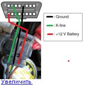
+ и — можно взять от аккумулятора, нужна только к-линия
-
#65
+ и — можно взять от аккумулятора, нужна только к-линия
Побежал попробую 
-
#66
Подключил. Pchud вобще не видит. Может куда нажимать надо в программе при подключении? Или там всё автоматом? Другая программа подключилась один раз и всё.
— — — Добавлено — — —
На колодке правильно у меня подключено? Потому что на остальных пишет связь прервана.
-
#67
регулятор холостого хода барахлит или плохой контакт
— — — Добавлено — — —
на приборке показывает историю ошибок. если сбой не повторяется то ошибка со временем пропадает
текущие ошибки можно посмотреть сканером или с помощью компа и кабеля http://forum.atvclub.ru/showthread.php?103072-Компьютерная-диагностика-Stels-500h-700h-efi-soft!
-
#68
Не правильно! на картинке правыйнижний, а у тебя левыйверхний. Как можно так не внимательно смотреть?
— — — Добавлено — — —
наверняка ты и +- поэтому не нашел
Последнее редактирование модератором: 29 Янв 2015
-
#69
Правый нижний тоже пробовал, результат тотже. Подключается через раз, но в другой программе. Pchud молчит.
-
#71
Только пар. Где худ указывать, так и не нашёл.
-
#73
)))) уже всё меню облазил.
-
#74
fileopen — это HUD
setupparametеr file — это PAR
файлы в папках надеюсь сам найдёшь
-
#75
Ооо, нашёл. График появился, но не подключается до сих пор.
-
#76
попробуй на заглушенном двигателе и включенном зажигании
— — — Добавлено — — —
кнопка глушилки должна быть нажата
-
#77
Тоже самое. Снизу программы постоянно висит com timeout error. И не пытается подключится.
Что за кнопка глушилки?
-
#78
провод куда вставил?
— — — Добавлено — — —
перезапускай прогу вставляй вытаскивай кабель
— — — Добавлено — — —
ещё проверь номер com порта т.к. для каждого usb задаётся свой номер com порта. Если воткнул не в тот usb то работать не будет.
кстати какая прога у тебя подключилась?
-
#79
Автоматом у меня устанавливает на 7,8, или 9 ком порт. Я в ручную переставляю на 1 ком порт. Пробовал и на заведёную и на просто с включёным зажиганием. Программа kwp2000. Она подключает иногда, через некоторое время после считывания данных, сбасывает связь.
Может что с мозгами на квадрике? Такое ощущение, что они не дают считывать информацию.
-
#80
попробуй другой com порт не первый. 1й com может быть изначально занят системным com портом.
-
#77
PCHUD.zip
В качестве к-лайн адаптера использовал vag-com kkl , только он смог непревывно держать связь с эбу
Настройка проги
-
#78
Какой протокол используется KWP2000 или ISO-9141-2 ???
-
#79
KWP2000. Неужели трудно посмотреть ролик по настройке ПО, специально выложенный.
Последнее редактирование: 24 Дек 2020
-
#80
Смотрел спасибо, пока непонятно зачем разные эбу выбирали для чтения ошибок.
-
#81
PCHUD корректно отображает параметры и ошибки, но НЕ всегда удаляет ошибки (хз почему.)
OpenDiag PRO удаляет ошибки, но не корректно отображать параметры. Я не стал подключаться
этой прогой, да и сохраненных, как и текущих ошибок у меня не было.
ХЗ, что она сует в ЭБУ при выборе Боша.
-
#82
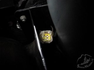
Доброго дня. Подскажите , Росомаха 2014 года, в диагностической фишке на снежинке 4 пин пустой. В нем нет разъема. Как понять которая K- line?
-

321,9 KB
Просмотры: 125
-
#83
РМ начали наши мозги ставить
-
#84
Доброго дня. Подскажите , Росомаха 2014 года, в диагностической фишке на снежинке 4 пин пустой. В нем нет разъема. Как понять которая K- line?
-
#85
Нет. У меня «-» как на фото, а «+» где нарисован «к-лайн» между ними 12 вольт ,а где нарисован «+» по идее должен быть «к-лайн» , но в ней нет контакта, разъем пустой, написал же.
-
#86
Всем привет подскажите пожалуйста блоки управления викинга и викинга 2.0 есть разница говорит что там программное обеспечение новое Что изменилось. Можно поставить Блок управления двигателем с викинга 2.0 на Ермак
-
#87
Всем привет подскажите пожалуйста блоки управления викинга и викинга 2.0 есть разница говорит что там программное обеспечение новое Что изменилось. Можно поставить Блок управления двигателем с викинга 2.0 на Ермак
У ермака и росомахи сильно отличались. Перепрошивали когда только ермак вышел.
Но заводится и ездить думаю будет. На сайте дилера посмотри в каталоге и сравни номера, одного и другого.
-
#89
У ермака и росомахи сильно отличались. Перепрошивали когда только ермак вышел.
Но заводится и ездить думаю будет. На сайте дилера посмотри в каталоге и сравни номера, одного и другого.
На сайте я посмотрел номера разные на Ермак продают три вида мозгов одни для Ермака двое для викинга немогу понять в чем разница мож кто-нибудь обяснит По-русски ? кто-то же разбирается программном обеспечения В чем отличие Дилеры никто не может ответить на вопрос. Заранее буду благодарен!
-
#90
Раздница в программе так ермак заводился с ключа а росомаха нет. Это прописано в эбу. И так далее.
-
#91
Коллеги.Доброго.
Стоит вот такое ЭБУ(Викинг V800 2.0 выпуск 2019г):

Предлагают такое…,в чём разница? подойдёт ко мне?

-
#92
предлагают более продвинутое
памяти больше
а прошивка хрен знает какая залита
-
#93
Доброго времени. Стала выскакивать ошибка 1693, после запуска загорается секунд 30. Запуск хороший, работает ровно, датчик коленвала менял. Что еще посмотреть?
-
#94
Есть софтинка получше чем древняя PCHUD и вроде как умеет удалять ошибки. Кто владеет английским или Гугл-переводчиком — смотреть здесь — https://netcult.ch/elmue/HUD ECU Hacker/
Перевод для программы. Файлы сменить разрешение на xml. Первый закинуть в папку C:Program Files (x86)HUD ECU HackerTranslation. Второй файл убрать 0 и закинуть в папку C:Program Files (x86)HUD ECU HackerECUMT05Translation.
-
71,3 KB
Просмотры: 205 -
62 KB
Просмотры: 198
-
#95
Доброго времени. Может кто повытаскивать флеш-файл прошивки этой программкой, для сравнительного анализа. Прошитые, стоковые. Интересует какая производительность форсунок в разных прошивках.
-
#96
этой программкой никто не вытащит то что назвал. если у тебя двигатель ругается на неисправность — сначала надо удалить неисправность. на такие редкие движки калибровщика и программу для изменения коррекций не найдешь никогда, залив прошивку другого движка получишь говно, мозгов с большей чем необходимо для управления движком памятью НЕ БЫВАЕТ
-
#97
через 30 секунд после запуска движка может загораться только первый лямбда-зонд из-за неисправности цепи его подогрева (кислородный датчик в глушителе тот что ближе к цилиндрам)
-
#98
забыл уже все по бензинкам, через 30 секунд ваш эбу начинает ругаться по поводу незапланированного количества кислорода в выхлопе. тут может быть что угодно — масложор, маленькое давление в топливной рампе, ссат форсы, нет компрессии, дырка во впускном или выпускном коллекторах, может еще что. вам диагност нужен.
-
#99
этой программкой никто не вытащит то что назвал. если у тебя двигатель ругается на неисправность — сначала надо удалить неисправность. на такие редкие движки калибровщика и программу для изменения коррекций не найдешь никогда, залив прошивку другого движка получишь говно, мозгов с большей чем необходимо для управления движком памятью НЕ БЫВАЕТ
Сам пробовал? Все вытаскивается и корректируется. Файлы нужны для сравнения таблиц, а не для заливки.
Последнее редактирование: 12 Дек 2021
-
#100
через 30 секунд после запуска движка может загораться только первый лямбда-зонд из-за неисправности цепи его подогрева (кислородный датчик в глушителе тот что ближе к цилиндрам)
Какие 30 сек? Если по моей ошибке, она горит 30 сек после запуска и пропадает. Ошибка моя к данному вопросу отношения не имеет.

 Ваши права в разделе |
|
Вы можете скачивать файлы скор. 128.0 Кб/s. Вы не можете загружать файлы на сервер Вы не можете загружать изображения к файлам Вы не можете редактировать свои файлы Вы не можете удалять свои файлы Вы не можете использовать докачку файлов |
Общие правила
-
Вы скачиваете и используете выложенные здесь материалы, программы и файлы «как есть», на свой страх и риск.
-
Администрация не несет ответственности за материалы, загруженные посетителями форума. Администрация не несет ответственности в случае любого ущерба, вызванного нуемалым или некорректным использованием материалов или программ, выложенных в архиве. Всегда проверяйте содержимое архивов антивирусным ПО после скачивания.
-
Перед тем как закачивать файл, пожалуйста, убедитесь в том, что данной информации нет в файловом архиве. Постарайтесь максимально ёмко описать вложение и сделать скриншот (несколько), где это возможно. Проверьте архив антивирусным ПО перед закачиванием на сервер.
-
Строжайше запрещены для выкладывания хаки, кряки и взломанные версии программ российского производства. Загрузка на файловый архив данного контента наказывается перманентным баном в архиве и на форуме без обсуждения и предупреждения.
-
О всех нарушениях авторских прав, несоответствии выложенной информации описанию, некорректно оформленных загрузок или обнаружении вредоносного ПО сообщайте администрации.
-
Модераторы имеют право удалять файлы, нарушающие правила архива, переносить их в другой раздел, редактировать описания к файлам и пр.
Быстрый переход
Текущее время: 13:07. Часовой пояс GMT +4.
разобрался)
тут
http://forum.atvclub.ru/index.php?threa … st-4245090
подробности,как подключаться к стелс с похожими мозгами …. у нас все тоже самое. только разъем на квадре у нас несколько иной = провода от переходника с его 16 пинового разъема …. сначала подключаем минус к зеленому проводу в нашей колодке …. потом плюс к красному в нашей колодке …. и К-линия к оставшемуся сиреневому в нашей колодке. Если все правильно, то на адаптере ККL загорится крас. диод. Именно в такой последовательности, чтобы ничего не сжечь. У нас + на колодке есть всегда. После этого только втыкаем USB в комп. Естественно там предварительно должны быть правильно установлены дрова адаптера и иметься описанное в ссылке ПО. Отключаем все на заглушенном квадре с выкл. зажиганием в обратной последовательности, предварительно закрыв все По на ПК, чтобы не было обмена данными.

по поводу адаптера … если будите покупать дешевые китайские варианты (а большего и не надо — работают любые), то есть один нюанс с дровами …. ставьте те, что идут в комплекте с адаптером, если по каким — либо причинам потребуется обновления, то ищите в нете дрова для вашей ОС и имейте ввиду.
Драйвер (последний официальный), который есть на официальном сайте FTDI (это основной чип адаптера) не устанавливайте, ставьте с диска, бывают случаи, когда слетает настройка чипа FTDI (относится ко всем китайским адаптерам на клонах официального чипа FTDI). Если не пойдет драйвер с диска, то попробуйте установить старые драйверы версии 2.8.14 (по тестированиям это последние драйверы, которые работают стабильно с китайскими адаптерами на аналогах чипа FTDI).
драйверы версии FTDI 2.8.14
https://yadi.sk/d/VGyPJp-Wia7pu
для чипов «FTDI»
если попался китайский адаптер на совсем бюджетном чипе ch340t то при проблеме с дровами можно попробовать эти
https://yadi.sk/d/Wb9tHOrpia837
Then you can either use a crimping plier or solder the wires to the contacts
and build your cable as shown in this video.
If you have time you can also buy a complete cable in China. Shipping may take between 1 and 3 months.
The red cable from Taobao has a very limited support of baudrates.
In the window «Configure Adapter» you must switch to Fast Init Mode 2 otherwise you get a timeout when connecting.
Therefore I implented the Echo Test into HUD ECU Hacker. It sends data to the K-Line adapter and verifies the echo.
You can execute the echo test after connecting the K-Line / VAG adapter to the motorbike.
But turn the ingnition key OFF so the ECU switches to sleep mode.
The echo test will fail if you connect only the adapter over USB to the computer. The +12V are required.
The +12V at the ECM plug are connected directly to the battery and are not affected by the ignition key.
You can also test the pure USB to RS232 adapter by connecting RxD (pin 2) directly to TxD (pin 3).
J2534 adapters are the recommended choice. They support K-Line and CAN bus.
J2534 (PassThru) is an international standard for reprogramming ECU’s.
If you are interested in the details read the API Documentation (PDF) for programmers.
There are also chinese clones like the VISLONE Tactrix Scanner for 30€ which have been reported to work fine.
ATTENTION: Do not buy XHorse Mini-VCI adapters. They are Chinese fake garbage.
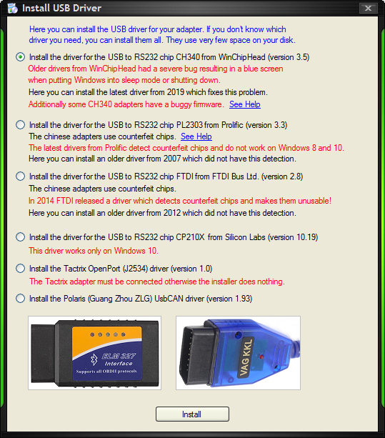
When you plug in the adapter for the first time Windows installs a default driver and assigns a COM port.
ATTENTION: This is the wrong driver and the COM port will never work.
In the HUD ECU Hacker toolbar (button «Install USB driver») you can install the original Tactrix driver.
After installing the correct driver the COM port will disappear and a J2534 device will show up in Control Panel:
ELM327 / ObdLink /Scantool adapters support K-Line and CAN bus.
Do NOT buy any of the cheap Chinese ELM327 adapters which are sold on Amazon or eBay!
They are all fake and work only partially. Many ELM327 commands are buggy or even not implemented at all.
If you see one of the following errors in the HUD ECU Hacker Trace pane, the Chinese have betrayed you:
The buffer of the fake adapters is so tiny that it cannot even receive a 128 byte ECU response!
So you can only scan the OBD2 commands which give few information, but not the detailed vendor specific commands.
You will see none of the above errors if you use a genuine OBDLink adapter.
Some chinese USB adapters use a counterfeit PL2303 chip (right photo) which converts from USB to RS232.
On Windows XP and Windows 7 this works perfectly.
But on Windows 8 and 10 the latest drivers from Prolific detect the counterfeit chip and refuse to work.
The driver returns the undocumented Error 433: «A device which does not exist was specified.»
If you connect the adapter and Windows 10 does not find an installed driver it downloads the latest version 3.8
from Windows Update and you will see a yellow exclamation mark or a ‘PHASED OUT’ error:
On the right photo you see that there are several SMD parts missing (4 transistors and 16 passive components).
This means that the J1850 bus will not work. Only CAN and K-Line are implemented.
If a vendor sells this as a universal ELM327 adapter, this is a fraud.
However, the J1850 bus was used by older GM and Ford vehicles, but is not used in modern cars anymore.
Follow these steps on Windows 10 to add a bluetooth adapter: (on Windows 7 it is similar)
One of the COM ports will work while the other one will not be functional.
Simply open the COM ports in HUD ECU Hacker and try them (the LED «PC» on the adapter should flash).
These adapters are the most stupid design because they represent a WIFI access point.
Mostly they respond on the fix IP address 192.168.0.10 and port 35000 without WIFI password.
The problem is that you must disconnect your notebook from your router to connect it to the adapter.
So after connecting to the OBD adapter you lose internet access.
The signal strength and maximum distance between computer and adapter are worse than with Bluetooth adapters.
The adapter uses the most used Wifi Channel 11. So conficts with your or your neighbour’s router are probable.
There is absolutely no reason why should buy these adapters.
If you already have a Chinese ZLG (Polaris) UsbCAN adapter, you can use it with HUD ECU Hacker.
However, do not buy one because it supports only CAN bus and the driver is worst Chinese ‘quality’ with many bugs.
Most of the pins are fake. Only the uppermost (CAN0H and CAN0L) are connected internally.
The LED’s are extremely stupid: Red LED blinking means OK. Green LED illuminated means CAN bus error.
To install the driver click the toolbar button Install USB driver in HUD ECU Hacker.
The ISO 9141 protocol is quite old and primitive.
The data transfer on K-Line (Pin 7) is like RS-232, sending the least significant bit first, but the voltage is inverted.
ISO 9141 uses the extremely slow 5 Baud Init to wake up the ECU. It takes 2 seconds to transmit the address byte (0x33).
Some ECU’s require this 5 Baud Init to be sent additionally on L-Line (Pin 15).
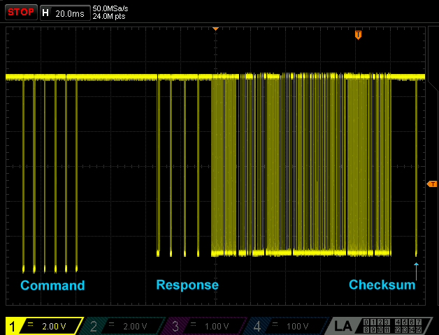
Here you see the first OBD2 command 01 00 (Request supported PID’s) and the response from the ECU.
The command is embedded into a packet which starts with a header and ends with a checksum.
ISO 9141 does not define error codes.
The ECU simply does not respond when it does not understand a command.
The Keyword 2000 protocol (KWP 2000) is defined in ISO 14230. It offers much more functionality than ISO 9141.
ISO 14230 normally uses Fast Init to wake up the ECU.
Fast Init means that the K-Line goes low for exactly 25 ms and then high for 25 ms. After that the communication starts with 10400 baud.
However, there are a few ECU’s which combine the ISO 14230 protocol with 5-Baud Init.
On the left you see the fast init, followed by the command ‘Start Communication’ and the response from the ECU.
On the right you see that ISO 14230 demands long pauses between the bytes because some old ECUs are very slow.
The Delphi MT05 uses the address 11. The application on the PC (the tester) uses the address F1.
The MT05 responds with 2 key bytes EF and 8F which define how the ECU wants the commands to be formatted.
They define how to transmit the packet length and if the source/target addresses are to be sent.
You see the meaning of the key bytes in the Trace pane in magenta when connecting.
The first header byte is called format byte.
It may contain the packet length and it’s bits define if addresses are sent and the type of addresses (physical, functional).
To simplify reading the binary data HUD ECU Hacker displays the data bytes in parenthesis in the Trace pane:
The other bytes are not really interesting as they are generated automatically.
The following table shows a long response (102 data bytes) which contains an additional length byte (header 4).
HUD ECU Hacker tries first to connect with the physical address defined in the parameter XML file (Default = 0x11).
If this fails it waits 5 seconds and tries again with the functional address 0x33.
A physical address (format byte contains 0x80) means that one specific device on a bus is addressed.
A functional address (format byte contains 0xC0) is like a broadcast address to a group of devices.
There are functional addresses for Steering Controllers, ABS Systems, Air Condition, Audio, Lightning, etc.
The functional address 0x33 is used to address «Engine Controllers» (ECUs).
As normally only one ECU is connected this can be used when the physical ECU address is unknown.
As you see here the ECU responds to the functional address 0x33 with it’s physical address 0x11:
The Delphi MT05 does not need functional addressing, but there are strange ECU’s which do not respond to their own physical address!
ISO 14230 defines several error codes which the ECU can return.
If the ECU does not understand a command it sends 7F (failure) followed by the service and the error code.
If the ECU does not receive commands it switches to sleep mode after 5 seconds.
While HUD ECU Hacker is polling data this will never happen because polling takes place 3 to 5 times per second.
Only if you switch to manually enter commands (in the Trace pane), polling stops and HUD ECU Hacker sends a Keep-Alive every 3 seconds.
Newer vehicles are equipped with CAN bus which uses 2 wires (CAN Hi and CAN Lo) and runs mostly at 250 or 500 kbaud.
Many controllers and sensors may be connected to the same bus. Each endpoint has a unique ID.
The neutral voltage on CAN bus is 2.5 Volt. Each endpoint has a transmitter which pulls CAN Hi up and CAN Lo down.
The receiver measures the difference between CAN Hi and CAN Lo which makes CAN robust against electromagnetic interference.
Below you see a raw CAN frame which contains the identifier (11 bit or 29 bit) and max 8 data bytes.
Data transfer is very robust because a 15 bit CRC assures that each frame is received without error.
The ISO 15765 protocol can transmit a payload of up to 4095 bytes in multiple raw CAN frames of 8 bytes.
It occupies the first data byte of each CAN frame as a control byte.
The first byte may define that the frame is a SF (Single Frame) which transmits only 7 data bytes.
Or a FF (First Frame) followed by multiple CF (Consecutive Frames) and FC (Flow Control Frames) transport a larger payload.
Mostly (but not always) ECU’s use 2 different CAN ID’s: One for receiving and one for sending.
OBD2 compliant ECU’s with 11 bit ID should respond to the functional broadcast ID 7DF.
They use a phyical ID between 7E0 … 7E7 for receiving commands and 7E8 … 7EF for sending the response.
If only HUD ECU Hacker and the ECU are connected to the CAN bus you do not need CAN filters.
But if you sniff the CAN bus traffic in a car or a truck you may get a tremendous amount of data.
A filter and a mask can be used to exclude all the other traffic on the CAN bus except to the ECU.
The filtering also tells the adapter which packets to acknowledge (set the bit in the ACK slot of the CAN frame).
If HUD ECU Hacker runs in sniff mode it will never modify the ACK bit.
Otherwise, when communicating with the ECU or in Emulator mode the received packets must be ACKnowledged.
If a CAN packet is not ACK’ed by the receiver the sender assumes that it was not received and sends it again.
If a CAN packet is not ACK’ed mutiple times the sender generates an error and stops the communication.
For Can Raw protocol you must enter RespFilter and RespMask in the parameter XML file.
For ISO 15765 these are not needed. You enter a fix RespID instead.
In the field ‘Response ID’ enter an ID on which the ECU responds and the filter and mask will be calculated automatically.
If you know the ECU ID enter it into the field ‘Response ID’.
If you enter 7E8, the filter and mask will be calculated as 7E8 and 7FF.
Otherwise use the letter ‘X’ to specify that a digit does not matter (e.g. 7EX). A digit corresponds to 4 bits.
If you enter 7EX, the filter and mask will be calculated as 7E0 and 7F0.
If the precision of 1 digit = 4 bits = 16 matches is not enough you must enter filter and mask manually.
| Example 1 | Example 2 | Example 3 | |
|---|---|---|---|
| Response ID | 7E8 = 111 1110 1000 | 7EX = 111 1110 XXXX | empty |
| Response Filter | 7E8 = 111 1110 1000 | 7E0 = 111 1110 0000 | 7E8 = 111 1110 1000 |
| Response Mask | 7FF = 111 1111 1111 | 7F0 = 111 1111 0000 | 7FC = 111 1111 1100 |
| Received ID’s that match the filter and mask |
7E8 = 111 1110 1000
only 1 ID matches |
7E0 = 111 1110 0000 7E1 = 111 1110 0001 7E2 = 111 1110 0010 7E3 = 111 1110 0011 7E4 = 111 1110 0100 7E5 = 111 1110 0101 7E6 = 111 1110 0110 7E7 = 111 1110 0111 7E8 = 111 1110 1000 7E9 = 111 1110 1001 7EA = 111 1110 1010 7EB = 111 1110 1011 7EC = 111 1110 1100 7ED = 111 1110 1101 7EE = 111 1110 1110 7EF = 111 1110 1111 16 ID’s match |
7E8 = 111 1110 1000 7E9 = 111 1110 1001 7EA = 111 1110 1010 7EB = 111 1110 1011 4 ID’s match |
Each bit in the mask which is one defines that the same bit in the filter must match the same bit in the ID of the received CAN frame.
Each bit in the mask which is zero defines that the same bit does not matter, neither in the filter nor in the ID of the received CAN frame.
PCHUD & Diag Tool
The Delphi manuals for MT05 and for MT20 explain a software PCHUD.
PCHUD (‘Heads Up Display’ for PC) is a very old program from Delco Electronics written in 1993 for Windows 3.
The manual for the MC21 explains a software Diag Tool from LITEON written in 2009.
Previously these were the
only
programs that could communicate with these ECU’s.
Today it is practically impossible to find this software in internet.
I found lots of dead links and a fake PCHUD download on a chinese website which was a trojan.
But in the forum China Riders I found a thread from the (ex)user ‘katflap’ talking about PCHUD.
Only thanks to ‘katfalp’ I could still in the year 2020 download and analyze this software.
The ancient 16 bit program PCHUD does not run on 64 bit Windows because Microsoft has removed the support for 16 bit applications on 64 bit platforms.
Running it on a 32 bit Windows in the 16 bit emulator (NTVDM.exe) I notice that it permanently occupies 100% of one CPU core.
While PCHUD is displaying the data from the ECU it sends every 200 ms the same command (21 01) which the ECU responds with a data block of 100 bytes.
This ‘parameter polling’ looks like this:
 |
| Show Full Size |
It was a lot of work to analyze which meaning has each of the 100 bytes in the response
and to find the formulas which convert the raw values into temperature, voltage and pressure.
HUD ECU Hacker
The ancient PCHUD from Delco is obsolete because
- it supports only one ECU model (MT05)
- it does not run on 64 bit Windows
- it occupies permanently 100% of a CPU core
- it cannot be connected over an ELM327 or J2534 adapter
- it cannot clear DTC fault codes (the menu is permanently grayed out)
- it can only display 36 parameters at the same time
- it shows the gauge for negative values wrongly
- it is clumsy to use and uses undocumented PAR, HUD, SLW, LGC, LGG, SCR, CFG and PLY files
The Diag Tool from LITEON is obsolete because
- it supports only one ECU model (MC21)
- it is a very sloppy software with ugly bugs
- it cannot be connected over an ELM327 or J2534 adapter
- it shows definitely wrong data for some parameters
- it can only display 36 parameters at the same time
- in the english version many translations (from Chinese) are missing
The new HUD ECU Hacker from ElmüSoft
- runs on Windows XP, 7, 8, 10 and 11 (not on Linux)
- runs on 32 bit and 64 bit Windows
- supports K-Line, J2534, ELM327 (USB, Bluetooth, Wifi) and UsbCAN adapters
- can install the Windows drivers for all supported adapters
- supports multiple ECU models over K-Line and CAN bus
- automatically detects protocol, baudrate, bus init when using parameter file ‘Autodetect OBD2.xml’
- shows fault codes (DTC) with a text explanation
- can clear fault codes (if supported by the ECU model)
- shows all ECU parameters at once in a user-configurable dashboard (90 params for the MT05)
- shows detailed tooltips for all parameters and their meaning
- can be adapted to any ISO 9141 / 14230 / 15765 / CAN Raw ECU by editing 3 XML files
- the user can enter formulas to convert raw data into temperature, voltage or pressure
- can capture the parameter data from the ECU in a logfile
- can export a logfile to a CSV file
- can create graphs from a logfile
- shows the entire communication with the adapter in the Trace pane
- allows you to manually enter commands and send them to the ECU for testing
- has a built-in CAN bus debugger / analyzer
- can emulate any ISO 14230 or ISO 9141 or ISO 15765 or CAN Raw ECU
- the emulator has a built-in formula finder
- can sniff the data traffic on the bus (for example from a scan tool or from another OBD software)
- can sniff ISO protocols, CAN Raw, Honda Keihin and KW 1281
- can extract vendor specific PAC files for MT05, MT05.2, MT05.3, SE08, MSE6.0, MSE8.0, Athena, MC10, MC21
- can decode hexadecimal S19, CAL, HEX, CUT, PTP, EFT files
- is optimized in each line of it’s code for the highest possible speed
- has multi-language support. You can translate the user interface and scan parameters into any language.
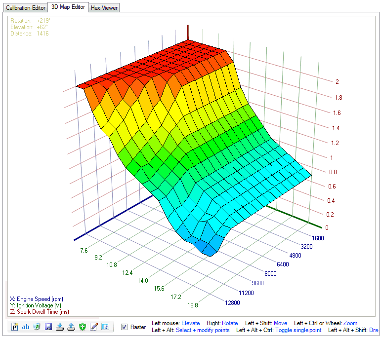
MT05 specific: - has full tuning support (editing calibration maps, tables, scalars), also with 3D Editor
- can download the flash memory from the Delphi MT05
- automatically detects the addresses and types of maps, tables, scalars and DTC codes in the flash memory
- has a built-in Hex viewer which shows the binary flash memory
- can program the flash memory with the calibration tables and ECU firmware into the MT05
- the user can create Patch files which contain the changes to be applied to a flash file before uploading
|
In contrast to all other OBD2 software HUD ECU Hacker is not commercial paid software. Also, HUD ECU Hacker will never show you any advertising. HUD ECU Hacker is the result of more than a year intense programming. There is absolutely no documentation about the internals of the MT05. All information you see in HUD ECU Hacker is based on a huge work which costs a lot of time. However, this program is charityware, which means that the author does not earn any money with it. But if this program has helped you saving money by not needing expensive commercial software Like for example Shanti Bavan, a project which gives education for free to the poorest of the poor in India. There is an excellent documentary about this very special residential school on Netflix: Daugthers of Destiny |
 |
Apart from that HUD ECU Hacker has been designed to be community software.
Every user can adapt the program to his needs.
When you have adapted the XML parameter file for another ECU, you are asked to send it to me for publishing it.
HUD ECU Hacker — Control
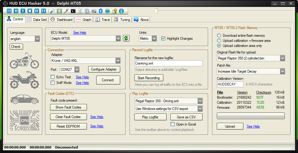
This screenshot shows the playback of the logfile Regal Raptor 350 — Error Clearing.xml
- I disconnected the plug of one oxygen sensor.
The plug has 4 pins: Two for the sensor and two for the heater. (See circuit diagram of MT05 above) - After turning on the ignition key the ECU immediately alerted error P0037. I did not even start the motor.
HUD ECU Hacker translates the fault codes into human understandable messages. - The error was first reported as Current.
- Then I turnd off the ignition, reconnected the oxygen sensor and turned on ignition again.
- Now the ECU detected that the error is not present anymore and reported it as Historic.
- Then I recorded the logfile
- At 00:00:10.200 I clicked the button Clear Fault Codes which removed the fault code.
Clearing Fault Codes (DTC)
The button «Clear Fault Codes» clears the historic fault code(s) from the non-volatile ECU memory.
But if a fault is still present it will not be cleared: You click the button and nothing happens.
This button will clear only historic fault codes which are not present anymore.
The MIL / EFI lamp is only on if there is a current fault present. It is off if there are only historic DTC’s.
Some current faults disapear immediately when the fault has been fixed (e.g. Oxygen sensor cable disconnected).
Other current faults will disapear alone after driving some minutes.
Some historic fault codes are erased automatically after driving 30 times without further faults.
The ECU can report multiple Current DTC’s at once and it can store multiple Historic DTC’s.
If there are multiple DTC’s present, they are displayed alternating once a second in the Dashboard.
You see all faults at once with their status when you click the button Show Fault Codes.
If you get the fault codes P0171 or P0172 please read the chapter Self-Learning.
HUD ECU Hacker — Data Grid
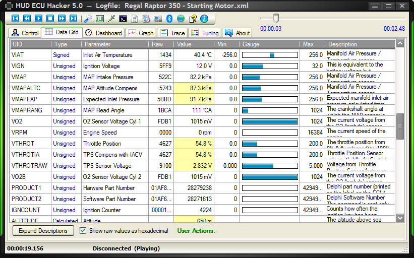
This screenshot shows the playback of the logfile Regal Raptor 350 — Starting Motor.xml
At 00:00:16.831 I turned the throttle up to the maximum with the motor not running.
At 00:00:32.712 I started the motor. You see that the ignition voltage drops down to 9.2 Volt.
At 00:01:55.106 I turned the throttle again, now with the motor running.
At 00:02:25.260 I pressed the kill switch (red button). The ignition voltage goes down to 0 Volt.
While recording this logfile the motorbike was standing still (not driving).
For each parameter you see the raw value and it’s meaning and the minimum and maximum values.
A gauge displays the value graphically. If the value can also be negative, the gauge starts in the middle.
Values that have changed since the previous sample have a yellow background. You can turn off this highlighting.
HUD ECU Hacker — Dashboard
The left screenshot shows the playback of the logfile Regal Raptor 350 — Driving.xml
At 00:00:35.878 I started the motor. The ignition voltage drops down to 7.7 Volt
At 00:00:39.488 the motor turned off alone because it ran too slow.
At 00:00:42.113 I started the motor again and drove around the block (not fast, ony first and second gear).
At 00:02:57.941 I pressed the kill switch.
On the screenshot above you see a tooltip which appears when you hold the mouse over a parameter.
Some parameters have a wrench icon. ![]() You can click on it and modify these values in the ECU. See Data Slewing.
You can click on it and modify these values in the ECU. See Data Slewing.
The dashboard can be configured 100% by the user after checking the checkbox Edit Mode below.
You can create, edit and delete groups and assign parameters to them.
You can move around the groups, change the order of parameters and drag and drop them to another group.
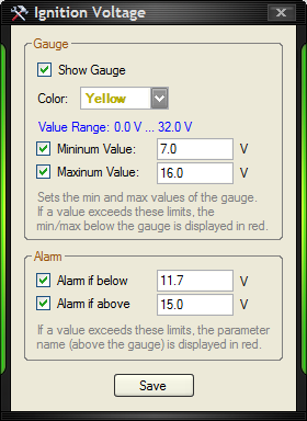
In this dialog you can configure a value parameter.
The ignition voltage has a minimum of 0 Volt and a maximum of 32 Volt.
You can restrict the range of the gauge to something more useful like 7 V to 16 V.
When you set an alarm the parameter will be displayed in red if the value exceeds the given limits.
HUD ECU Hacker — Graph
These images are graphs created from the logfile Regal Raptor 350 — Driving.xml
You can chose the parameters that you want to include.
If you want more sophisticated graphics you can export the data to CSV and
load it into the LiveLink Gen-II software (70 MB).
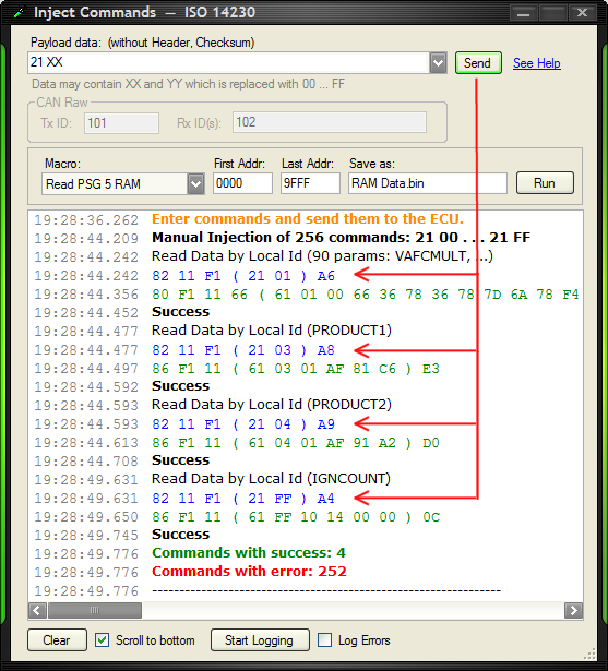
HUD ECU Hacker — Manual Command Injection
 |
| Show Full Size |
HUD ECU Hacker allows to send commands manually to the ECU and study the response.
For the purpose of hacking you can also enter XX, YY, which will be replaced with all values from 00 to FF.
In the example above entering ’21 XX’ has sent 256 commands from ’21 00′ to ’21 FF’ to the ECU.
Here the ECU (a Delphi MT05) has only answered 4 of the 256 commands, for the others it has returned an error.
Entering ’22 XX YY’ will send 65536 commands from ’22 00 00′ to ’22 FF FF’ to the ECU.
For the CAN Raw protocol you must also specify the Tx CAN ID for sending the command and the Rx ID for receiving the response.
Some ECU’s send multiple responses on multiple CAN ID’s to one command. In this case enter all Rx ID’s separated by commas.
Recording Logfiles
Below in the Trace pane with the button Start Logging you can create logfiles after connecting to the ECU.
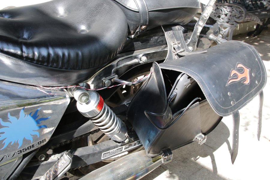
You can also record a log file while you are driving.
Connect the cables and put a notebook into a saddlebag or backpack.
 |
| Show Full Size |
Data Slewing
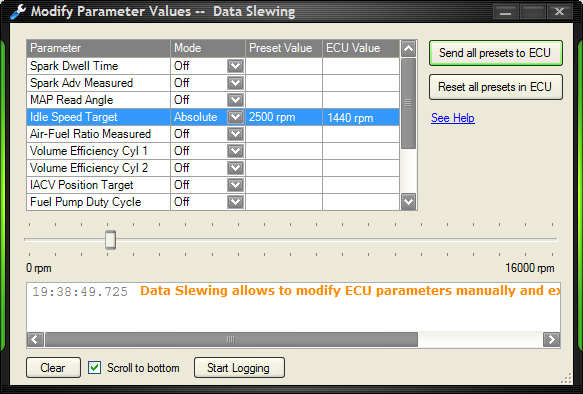
The MT05 allows to manually modify some of the parameter values which have been measured or calculated.
The purpose of data slewing is to analyze an engine which is not running correctly.
You can set absolute (fix) preset values or you can add a delta (± offset) to the current ECU values.
First set all the preset values that you want to change in the list then click ‘Send all presets to ECU’.
These changes have effect on the running motor.
Idle Speed
When the motor is runing idle and you set Idle RPM Target to 2500 rpm you will hear how it slowly becomes faster.
 |
| Show Full Size |
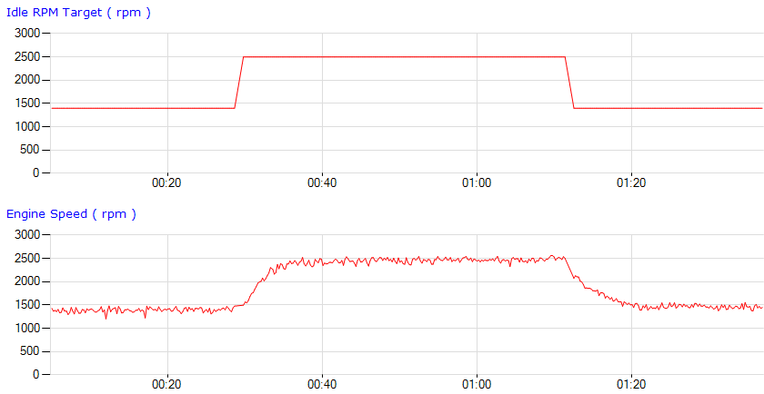
This graph shows the logfile Regal Raptor 350 — Data Slewing.xml where the engine was running idle with 1400 rpm.
At 00:00:29.806 I have set the slew parameter Idle RPM Target to 2500 rpm. The ECU slowly adapted the idle speed.
At 00:01:12.480 I have clicked the button Reset all presets in ECU.
NOTE: On a Benelli TRK251 (1 cylinder) you can set the idle speed target but the engine speed is not adjusted correctly.
Fuel Pump
When the engine is off and you set Fuel Pump Duty Cycle to 15% you will hear the fuel pump running quietly.
IACV
You can control the Idle Air Control Valve with the slew parameter IACV Target Step.
If you have problems with the idle speed read appendix IACV Calibration.
The modified slew values are not stored in the non-volatile memory of the ECU.
However this feature is for experts only. Wrong values can produce knocking or stall the motor.
I saw that the ECU does not go to sleep mode after changing some of the values.
Do not forget to click ‘Reset all presets in ECU’ when you are finished with your testing.
ATTENTION:
Data Slewing does not work with my chinese ELM327 adapters. But J2534 and K-Line adapters do work.
The ELM327 Datasheet says (page 31) that the ELM327 limits the bytes that can be sent to the maximum for OBD2.
Therefore HUD ECU Hacker sends the command ATAL which allows longer commands.
My chinese adapter answers ATAL with ‘OK’, but it still refuses to send more than 4 data bytes.
You will see a timeout error in HUD ECU Hacker.
ELM327 Terminal
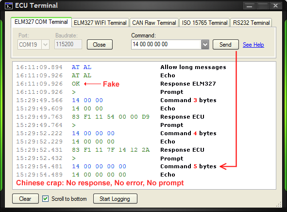
As there are so many problems with chinese ELM327 clones I implemented the ELM327 Terminal.
Here you can test your adapter by sending commands and studying the responses.
The screenshot shows that my ELM327 clone sends commands only up to 4 data bytes.
If I send 5 data bytes or more (like the Slewing commands) there is no response, no error and no prompt.
I verified on the oscilloscope that the adapter indeed does not send anything.
The command ATAL is simply ignored although it was answered with a fake ‘OK’.
It is a fraud to sell this crap.
By the way: It is completely irrelevant if a chinese adapter claims to be version 1.5 or 2.1. They are all crap.
And I saw people complaining in internet about ELM327 adapters which have even less functionality than mine.
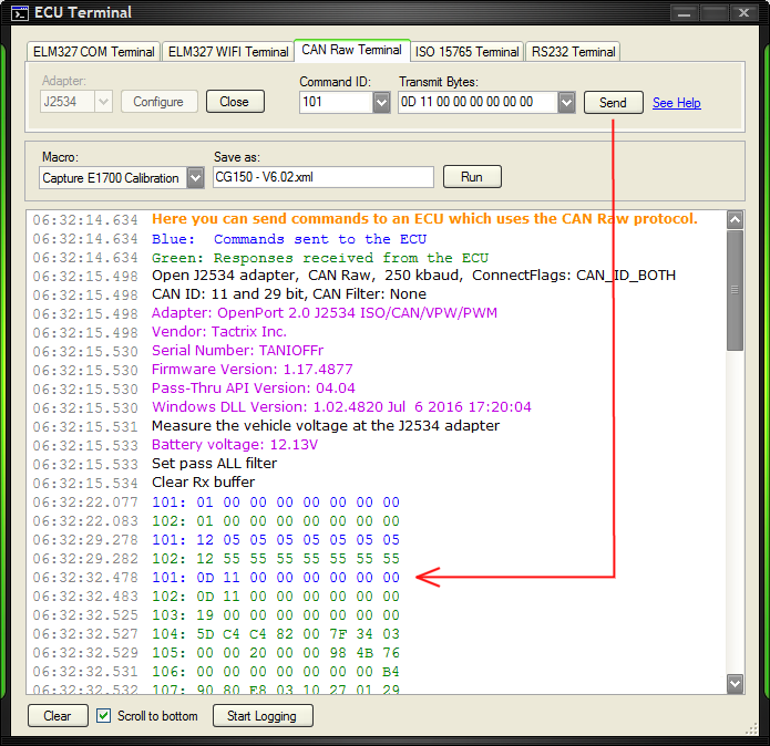
CAN Bus Debugger
 |
| Show Full Size |
HUD ECU Hacker can also be used as CAN Bus Analyzer / CAN Bus Debugger / CAN Bus Terminal.
In Sniff Mode you can see the entire traffic on the CAN Bus (not only to the ECU) in real time.
You can set filters to show only the packets which you are interested in.
And the CAN Raw Terminal allows to send commands directly to any device on the CAN bus.
Normally you must buy expensive proprietary adapters for professional CAN bus analyzer software.
HUD ECU Hacker allows to use a cheap chinese J2534 clone or a UsbCAN adpter.
Download / Upload Flash Memory (MT05 / MT05.2 only)
The heart of the the Delphi MT05 is a 16 bit Infineon processor.
The flash memory in the processor is divided into 4 areas:
- The Bootloader is required to start up the ECU.
It will never be overwritten when flashing. This is a protected area. - The Configuration Data will always change when you turn off the ignition key.
The ECU stores non-volatile data here when you turn the ignition key off, like:
fault codes, ignition counter, statistics, fuel learning (BLM), airflow learning and throttle learning.
HUD ECU Hacker does not write into this area, but you can erase the content of this erea. See Reset EEPROM. - The Calibration Tables are used to calculate the optimal operation of the motor depending on
factors like speed, engine load and temperature, etc. They control fuel injection, spark timing, etc. - The Firmware area contains the executable program code.
You should normally not overwrite this area except you know exactly what you are doing.
| Processor | Delphi MT05 | Delphi MT05.2 | ||
|---|---|---|---|---|
| Model | SAK-XC164CM-16F40F | SAK-XC164CS-32F40BB | ||
| Flash Memory | 128 kB | 256 kB | ||
| RAM | 8 kB | 12 kB | ||
| Clock | 32 MHz | 32 MHz | ||
| Flash Memory | Delphi MT05 | Delphi MT05.2 | ||
| Bootloader | 000000 — 003FFF | 16 kB | 000000 — 003FFF | 16 kB |
| Configuration Data | 004000 — 004FFF | 4 kB | 004000 — 004FFF | 4 kB |
| Calibration Tables | 005000 — 007FFF | 12 kB | 005000 — 00AFFF | 24 kB |
| Firmware | 008000 — 01FFFF | 96 kB | 00B000 — 03FFFF | 212 kB |
HUD ECU Hacker can download the flash memory into a file (flash download).
HUD ECU Hacker can also program the flash memory from a file (flash upload).
In the main window you see the versions and the checksums of the flash memory areas.
Green means the checksum is correct. Red means it is wrong and will be fixed when uploading.
ATTENTION:
If you use a K-Line adapter execute the Echo Test to assure that it works correctly.
If you use an ELM327 adapter it must be a genuine OBDLink adapter.
Before flashing for the first time store your original flash file in a secure place!
If flashing of only the calibration tables goes wrong your ECU may still communicate over K-Line.
But if flashing the firmware area goes wrong your ECU will probably be bricked.
See Rescue a bricked MT05.
Tuning (MT05 / MT05.2 only)
Tuning with Commercial Software
Tuning means to modify the calibration tables to get more power, cleaner emissions, or better fuel efficiency.
For tuning you normally have to purchase 2 expensive programs:
1.)
One program which only downloads and uploads the flash memory:
BitBox (250€, english) or
CombiLoader (base: 21500 rouble + MT05: 8000 rouble)
2.)
Another program for editing the calibration tables:
BitEdit (100€, english) or
ChipTuningPro (base: 2400 rouble + MT05: 10000 rouble)
Additionally you have to buy an USB dongle (30€) which protects their software from piracy.
BitEdit does not support all MT05 versions. Click here for a list of supported calibration versions.
While BitEdit shows 36 tables for the MT05 (in english), ChipTuningPro shows more than 200 tables.
BitEdit is compared with ChipTuningPro like a toy. It has bugs and shows some data and axis wrongly.
3.)
Other tuning software like ECM Titanium is even more expensive (> $1000 USD).
4.)
If you have a MT05 from Kohler or from Briggs & Stratton they sell you diagnostic software that is very restricted.
You are forced to buy their proprietary adapter (> $300 USD) which acts like a dongle.
Each time you start the software, it connects with their server and checks if you have a valid license.
The license is only valid for one year.
As you see clearly: All the tuning and even ECU scanning is a very profitable business. All these companies want your money.
IMPORTANT: A time consuming analysis must be done to get the correct meaning of scalars, tables, maps and their axes.
The companies which sell expensive tuning software do not invest the required time to do this tremendous work.
Doing a real analysis of each and every firmware version of each and every ECU model would result in a price that nobody is willing to pay.
So they enter much of the data by guessing and by copying it from other firmware versions, which results in a lot of wrong information.
Tuning with HUD ECU Hacker
With the charityware HUD ECU Hacker you save a lot of money by not having to buy commercial software.
Flash download, checksum correction and flash upload can also be done with HUD ECU Hacker.
Please do not forget to give a donation for using HUD ECU Hacker.
An issue with the MT05 is that each ECU firmware version stores the calibration tables at another address in the flash memory.
This means that there is no easy way to know how many tables exist and where each table starts and where it ends.
But HUD ECU Hacker analyzes the ECU assembler code and finds automatically 200 calibration tables and 500 scalar values.
It even finds the values and meaning of the axes of nearly all tables and maps by auto detection.
This works with all firmware versions and takes less than one second. The result is 100% reliable.
|
|
|
Whenever you load a new flash memory BIN file it will be automatically analyzed and the result is written into a file.
This file has a name like «Firmware_5D06BA79.definitions» and contains the maps, tables, scalars and axes that were found.
The hex number in the filename «5D06BA79» is a CRC (similar to a checksum) of the firmware area in the flash memory.
Each firmware version will generate it’s own definition file because each firmware version stores the calibrations at different addresses.
HUD ECU Hacker also detects the count of rows and columns and if the table data is 8 bit or 16 bit and if the data is signed or unsigned.
The auto-detection analyzes the assembler code in the ECU which gives reliable results independent of the firmware version.
The assembler code in the ECU is eternally long (printed on paper it would be one kilometer).
However HUD ECU Hacker does this analysis in less than a second. Here you see a snippet of the huge Delphi code:
c1768ef2 fc f8 f7 mov r12,[0xF7F8]c17692f2 fd fc f7 mov r13,[0xF7FC]c17696d7 40 01 03 extp #0x301, #1c1769af2 fe 22 29 mov r14,[0x2922]c1769eda c1 f8 14 calls FUN_c114f8c176a2f0 c4 mov r12,r4c176a4f6 fc f8 f7 mov [0xF7F8],r12c176a8f2 fd fc f7 mov r13,[0xF7FC]c176ac42 fd f8 f7 cmp r13,[0xF7F8]c176b0fd 08 jmpr cc_ULE,LAB_c176c2c176b222 fd f8 f7 sub r13,[0xF7F8]c176b6f6 fd f6 f7 mov [0xF7F6],r13c176bae1 12 movb RL1,#0x1c176bcf7 f2 e6 f7 movb [0xF7E6],RL1c176c00d 08 jmpr cc_UC,LAB_c176d2
As you see, assembler code is extremely cryptic. I spend several weeks in understanding what the ECU does internally.
I hope that you honor this tremendous work and be so honest to respect the charityware policy of HUD ECU Hacker.
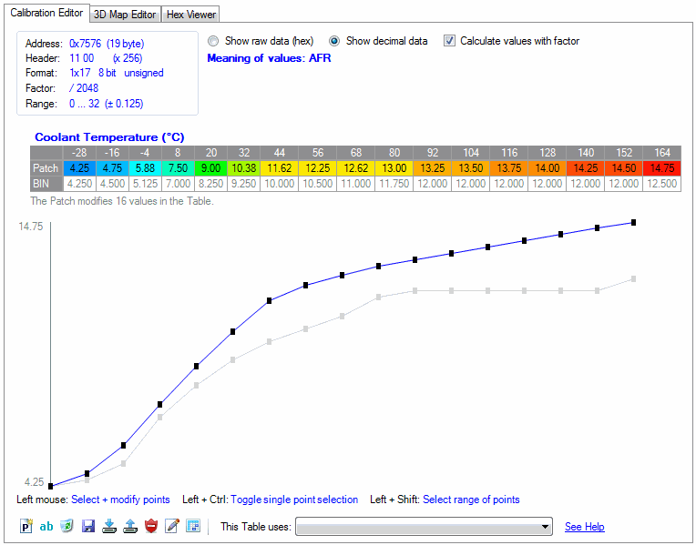
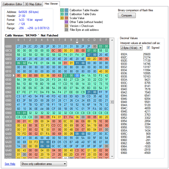
Hex Viewer
The Hex Viewer shows how scalars, tables and maps are lined up in the calibration area of the flash memory.
Reverse Lookup tables appear with bold text.
Axis values are calculated by a formula. The parameters for the formula are not stored in the calibration area.
You will see mostly two white areas of approx 30 bytes at the beginning of the calibration area.
All white areas contain tables which are never used by the firmware or they are filled with zeroes.
These tables are orphans. They contain data, that may be used in other firmware versions.
There are other tables which don’t have a header, so the length and type of data cannot be auto-detected.
They appear purple in the Hex Viewer.
The Hex Viewer can also compare two BIN files and show the differences.
Delphi Calibration Data
Please read this chapter in the help file.
Completing Auto-Detection Results
Please read this chapter in the help file.
Editing Calibrations
Please read this chapter in the help file.
Working with Patches
Please read this chapter in the help file.
Adapting to other ECU’s
HUD ECU Hacker can be adapted to any ECU which uses the ISO 9141 / 14230 / 15765 protocol.
This is a process in 5 steps.
You need the ECU and a scantool or software from the vendor which understands the vendor specific ECU data.
The traffic between ECU and scantool must be captured and reverse engineered. Doing this is not illegal.
IMPORTANT: A Universal OBD2 Scantool which only shows OBD2 data is useless. HUD ECU Hacker can already display OBD2 data.
The OBD2 standard has been designed to verify that a vehicle complies the emission laws.
OBD2 gives very limited information because the manufacturers implement only few commands, just the minimum to fulfil the law.
OBD2 may only show you Vehicle Speed, Engine Speed, Coolant Temperature, O2 Sensor and Throttle Position, and that’s it.
Generally ECU’s can report much more details to the service technician, but in a proprietary and secret data format of the manufacturer.
Only an expensive scantool or software from the ECU vendor may give you this information, but not a «universal» OBD2 scantool for all vehicles.
For example for the Delphi MT05 the vendor specific command 30 allows data slewing.
And the vendor specific command 21 returns details like crankshaft errors, stepper motor position, block learning (BLM) and much more.
These details (90 scan parameters) can not be obtained with a «universal» OBD2 scantool or OBD2 computer software.
The response of command 21 01 is a proprietary and undocumented data packet from Delphi.
I obtained the meaning of this 100 byte packet by analyzing the ancient PCHUD software.
You can do the same for any other ECU if you have a scantool or software which shows these details.
Step 1. Sniff Data
When you enable the checkbox ‘Sniff Mode’ you can capture the traffic between the ECU and a scantool / OBD software.
Connecting an additional sniff adapter over a splitter cable to the K-Line will mostly not work.
The reason is that each adapter has a pull-up resistor (mostly 510 Ω) between K-Line and +12V.
When you connect 2 adapters the parallel pull-up resistor becomes 255 Ω.
Adapters and ECU have a current limitation to protect them from shortcuts.
Most adapters don’t provide enough current (50 mA) to pull K-Line to ground over 255 Ω.
Depending on the pull-up resistor and the current limitation you will not capture anything or the scantool stops working.
Here you see the result of connecting two adapters at the same time. The voltage does not reach 0V anymore.
It may also happen that you can sniff data as long as the motor is off.
But when the motor runs the battery voltage rises to 15V and now you don’t capture data anymore or get crippled data.
The higher the battery voltage the more current is required to pull K-Line to ground.
However, there are also adapters with an internal pull up resistor of 1 kΩ. They may function unchanged.
The only bullet-proof solution is to modify an adapter and remove the SMD pull-up resistor between pin 7 and 16.
You can either convert an adapter into a sniff adapter by removing this resistor completely
or you can insert a switch into the adapter which allows to chose between normal mode and sniff mode.
No modification in the adapter is required for CAN bus sniffing.
The J2534 and ObdLink adapters require 4 pins to be connected.
If you use the UsbCAN adapter only 2 pins must be connected: CAN0H and CAN0L.
Store the sniffed data into a logfile by clicking the button ‘Start Logging’ in the Trace pane.
Navigate through all menus of the scantool to capture all commands.
IMPORTANT: If the logfile has many «Invalid Data» you have the wrong baudrate or the wrong protocol.
Step 2. Test the ECU Emulator
Connect HUD ECU Hacker to it’s own Emulator to learn how to use it.
You can use a battery or the 12 Volt from a cheap computer power supply (yellow wire).
ATTENTION:
ELM327 / OBDLink adapters do not have the functionality required for the emulator.
J2534 adapters will not work with any protocol that uses the 5-baud initialization.
Use a K-Line adapter for K-Line Emulation.
For CAN Bus an additional 100 Ω or 120 Ω resistor between CAN Hi and CAN Lo is indispensable because adapters do not have it built-in.
For K-Line select «Delphi + Rongmao MT05.xml». For CAN bus select «Delphi MT05.3.xml».
Then in the Emulator window click «Open», then in the main window click «Connect».
Now you should see the data coming from the emulated ECU in the dashboard.
Change the values of command 21 01 or 22 21 01 in the emulator and study their effect on the display in the dashboard.
Step 3. Simulate the ECU
Please read this chapter in the help file.
Step 4. Enter the XML Commands and Parameters
Please read this chapter in the help file.
Step 5. Enter the XML Names and Descriptions
Please read this chapter in the help file.
Download and Installation
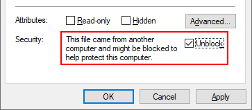
Windows may block the installer in the downloaded ZIP file because it has no digital certificate.
Please right click the ZIP file, select ‘Properties’ and check ‘Unblock’.
You need the .NET framework 4.0 or higher. On Windows 10 this is already installed.

In the toolbar at the top you can then install the drivers.
The toolbar also has a button that brings you with one click to the Device Manager, where you see all COM ports.
The toolbar has a tooltip for each button which appears when you hold the mouse over it.
 |
| Show Full Size |
Trouble Shooting
First try to connect with the parameter file Autodetect OBD2.xml which auto-detects the ECU’s protocol, init mode and address.
All newer ECUs will respond to OBD2 commands.
Errors when connecting to the ECU:
- The ignition key must be on.
- The kill switch must be in the position where it allows the motor to run.
- Some motorbikes (Benelli) require the side stand to be up otherwise the ECU will not respond.
- It is not necessary to start the motor to establish a connection.
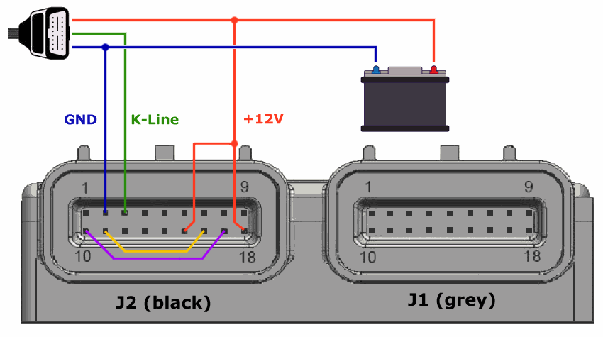
- Check that you have connected the 3 wires correctly as shown in this diagram.
- The voltage of the K-Line wire MUST be +12 Volt while the adapter is connected to the ECU.
Some adapters do not enable the pull up resistor when they are in power safe mode.
Measure the voltage after clicking the «Connect» button in HUD ECU Hacker which will activate the adapter. - If you use the K-Line or VAG adapter ecxecute the Echo Test to check the adapter.
- There are 2 types of timeout errors which indicate different errors:
- Timeout waiting for echo means always that you have a hardware problem or the wrong COM port.
- Timeout waiting for response (or received garbage characters) with ELM327 adapter may mean that the baudrate is wrong.
You can change the baudrate in the window «Configure Adapter». Normally the ELM327 has a default baudrate of 38400 baud.
However my genuine OBDLink adapter has a default baudrate of 115200 baud. - Timeout waiting for response with K-Line / VAG adapter may happen rarely.
The reason is that the ISO 14230 protocol is very time critical. It demands 50 ±1 ms for the fast init.
But Windows as a multitasking OS is not very precise and the interval seen on an oscilloscope may vary from 45 ms up to 70 ms.
If the interval between fast init and the command ‘Start Communication’ exceeds the limits the ECU does not respond.
K-Line adapters are the only adapters where timing depends on the computer. J2534 and ELM327 adapters create a precise timing.
If you get this type of timeout error, try the following:- Click ‘Connect’ several times until it works. It may work 8 of 10 times.
- Some adapters (e.g. some SiliconLabs chips) do not support the way how HUD ECU normally generates the fast init pulse.
Try switching Fast Init Mode 1 / Fast Init Mode 2 in the window «Configure Adapter». - For slow computers you can enter in the same window a K-Line timing correction which is added to the 50 ms interval:

ATTENTION: If you enter an invalid value here you may screw up the fast initialization forever.
If changing this value did not solve your problem, reset the correction to zero otherwise you may never be able to connect.
To verify the timing you need a digital oscilloscope, otherwise it is pure try and error.
- BUSINIT: ERROR from an ELM327 adapter means that the adapter did not receive a valid response from the ECU.
- If your ECU is a Delphi MT05 the voltage at pins J2-18 and J2-15 (black plug) must be +12V otherwise you will never connect.
- If your ECU is not the Delphi MT05, use the parameter file Autodetect OBD2.xml which tries to auto detect the protocol.
- You can also change the configuration in the parameter XML file. Some older ECU’s use 9600 baud.
- If you have tried everything and the ECU still does not respond, test your adapter: Connect HUD ECU Hacker to it’s own emulator.
Therefore you need a second adapter. See Emulator
If you have any problem you can send me a log file of the Trace pane with the error message.
You can write me in english, german or spanish.
But first read this help!
You find my email at the end of the help file.
Appendix
Delphi MT05.3
Delphi does not produce the MT05 and MT05.2 anymore because the very old microprocessor is end of life.
Delphi sells now the successor MT05.3 which is Euro 5 compliant and uses CAN bus.
This ECU is a complely new development, using a modern 32 bit processor.
The consequence is that all my endless work for flashing the MT05 / MT05.2 is completely useless now for the MT05.3
May be some day in the future I will add support for flashing the MT05.3.
But this requires the work of another entire year of reverse engineering!
Rongmao MT05
The Rongmao MT05 sends the same scan parameters as the Delphi MT05, so it can be scanned with HUD ECU Hacker.
But apart from the identical case and the scan parameters this ECU has absolutely NOTHING in common with the Delphi MT05.
It has another PCB, different chips and processor and logically also another firmware than the Delphi MT05.
 |
| Show Full Size |
Rongmao has cut away the text on the processor so the model is unknown and reverse engineering is more difficult.
As you see this is a COMPLETELY different ECU, so flashing the Rongmao MT05 is not possible.
Rongmao has also changed the commands for flash upload/download and the security key.
Until today nobody was able to flash this ECU. I never heard of any PC software nor any scantool which can do this.
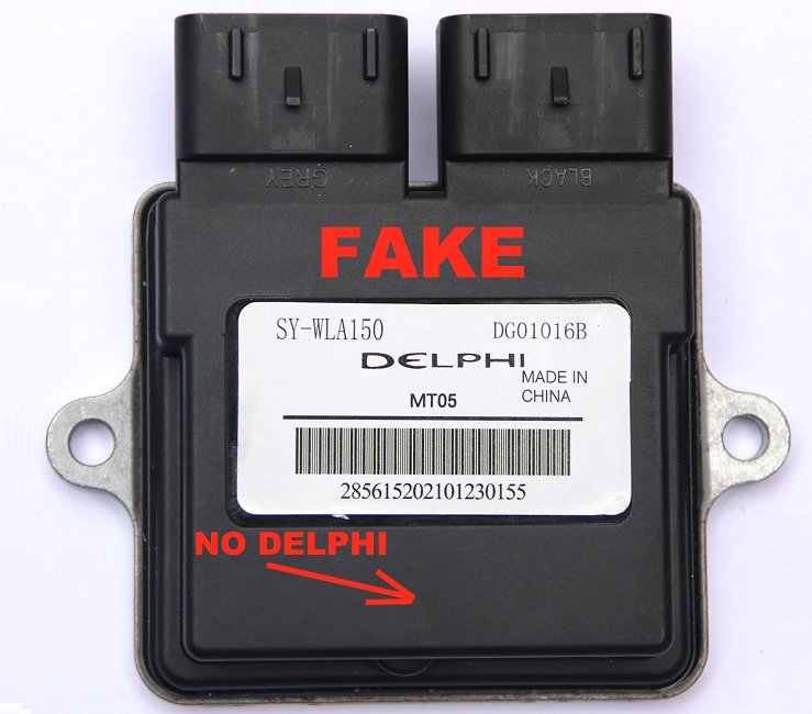
Chinese Fake MT05
Chinese fake clones of the MT05 or MT05.2 have appeared in the market which are garbage.
They are full of bugs and only the very basic OBD2 commands are implemented.
These ECU’s are so extremely buggy that they are not even able to send a correctly formatted DTC response!
Detailed scan data is not available, Data Slewing and flashing are not supported.
There are even fake MT05 which respond only on CAN bus instead of K-Line. (The real MT05 / MT05.2 does not respond on CAN bus)
HUD ECU Hacker will detect when you have connected a fake ECU and show an error message.
On the real ECU’s you see that «DELPHI» is engraved in the plastic of the cover. The fake does not have this.
 |
| Show Full Size |
Overheating Risk
A big problem of all combustion motors is overheating. If cooling fails, the motor will be damaged.
A water cooled motor will reach 80 degree Celsius, max 95 degree.
If the motor is air cooled the temperature may reach 140 degree.
- The first damaged part will be the cylinder head gasket. As a result coolant will enter into the cylinders and vaporize.
You will lose coolant through the exaust pipe. A vicious circle accelerating the damage.
Replacing the gasket is expensive because the motor must be opened. - If you drive longer with an overheated motor the cylinders will be ruined and you need a new motor.
The cause of overheating is a failure in the cooling system. This may be due to a defective ventilator or lack of coolant.
Some motorbikes (like my Regal Raptor) neither have a temperature display nor an overheating lamp.
This is a severe problem because the owner has no chance to check the temperature of the motor.
ATTENTION: The Delphi MT05 is so stupidly programmed that it does NOT protect the motor from overheating!
Although the ECU has a temperature sensor and knows the exact temperature, it will not turn the motor off when it becomes too hot.
The MIL/EFI light may turn on when it is already too late (Error P0117 at approx 200 degree) or it never turns on.
Check regularly if your motorbike has sufficient coolant! Use HUD ECU Hacker to check the current temperature.
If coolant disappears within a few days or weeks without a leak your motor is probably already damaged.
IACV Calibration
The IACV (Idle Air Control Valve) is like a bypass for the throttle valve.
It allows a small amount of air to enter into the engine while the throttle is closed.
If the IACV does not work correctly you may have the following problems:
- The engine cannot be started
- The engine goes off alone while running idle (especially when it is cold)
- The idle speed is irregular
- The ECU may generate fault code P0505.
The IACV has a stepper motor which moves a pintle precisely to a position between 0 and 255.
| Position 0 | Position 255 |
|---|---|
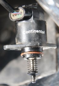 |
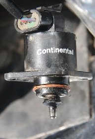 |
To maintain the stepper motor in the desired position a current must flow permanently which generates a magnetic field.
Therefore the stepper motor becomes warm although it does not move.
- Position 0: The valve is fully closed. Air can only enter through the throttle into the intake manifold.
- Position 168: The valve is in the parking position for the next cranking. (Defined in the calibration IAC Park Position).
- Position 200: The maximum position that the ECU will use. (Defined in the calibration IAC Position Max).
- Position 255: The valve is fully open.
You can use the Data Slewing window to test the IACV while the engine runs.
If you enter a delta value of +30 steps, more air enters and you notice that the idle speed increases.
If you enter a delta value of -30 steps, less air enters, the idle speed decreases and the engine may stall.
Aprox 5 seconds after turning the ignition key off the ECU parks the IACV and stores the pintle position in flash memory.
The IACV has no sensor which reports the current mechanical position to the ECU.
The ECU simply trusts that the position stored in the flash memory is the same as the real mechanical position.
But the range which the stepper motor can move is wider than the programmable range from 0 to 255.
So if the ECU loses synchronisation with the mechanical position you will have one of the problems listed above.
I found the following way to calibrate the IACV (while the engine is off) with the older MT05 ECU.
- Take the IACV out so you can see the pintle position.
- Connect HUD ECU Hacker.
- In the Data Slewing window move the IACV to the absolute position 255.
- Now disconnect the battery so the ECU cannot store this position in the flash memory.
- Reconnect the battery. You should hear the fuel pump running. Now the ECU assumes the IACV in parking position.
- Repeat steps 2 to 5 until the pintle does not move anymore. The spring must be completely compressed.
- Now you have the pintle in the real mechanical position 255.
- In the Data Slewing window click Reset all presets in ECU which moves the pintle to the parking position.
- Turn off the ignition key. Now the ECU stores the correct parking position in flash memory.
- Mount the IACV back into it’s place.
- When driving the next time the airflow self-learnig will adapt to the new conditions.
The newer MT05.2 already has the EEPROM Reset, which also adjusts the IACV, but in a different way.
The ICAV must be mounted in the throttle body while executing the EEPROM Reset.
The ECU will move the stepper motor until the pintle is mechanically blocked when the IACV is fully closed.
This will be the new position 0.
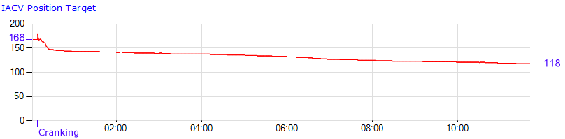
Play the logfile Regal Raptor 350 — IACV Idle Warmup.xml and create a graph with the preset IACV and Idle.
Here you see how the MT05 slowly adjusts the IACV during a 12 minute idle warm-up from 18 °C to 80 °C:
Self Learning
The ECU adapts to changing load, atmospheric pressure and fuel quality to keep the emissions at a minimum while running in closed loop.
It also compensates a worn out fuel pump or a dirty air filter.
Based on the O2 sensor feedback, the short term adaption increases (> 0) or decreases (< 0) the amount of fuel to get the optimal air/fuel mix.
If the short term adaption (Integrator) deviates too much, the long term adaption will be adjusted.
The long term fuel adjustment is stored in a table which contains Block Learn Multipliers (BLM).
Multipliers have values between 0.0 and 2.0 where values > 1.0 mean more fuel and values < 1.0 mean less fuel.
The Delphi MT05 uses a table with 36 cells (16 bit) for each cylinder which is stored in the flash memory.
|
|
The X and Y axis values come from the lookup tables ‘BLM MAP Boundary’, ‘BLM TPS Boundary’, and ‘BLM RPM Boundary’.
The Y axis may be based on MAP compensated pressure or throttle position. This is defined by scalar ‘BLM Load Option’.
The rolling idle cells are used when the engine is idling.
While the engine is running you see in the dashboard which cell the ECU is currently using and what is the value of this cell:
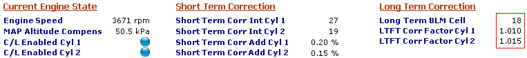
This capture is from logfile ‘Regal Raptor 350 — Driving.xml’ at 01:16:246
A long term correction factor of 1.015 means adding 1.5% more fuel.
The ECU also learns automatically which voltage of the throttle sensor corresponds to 0% throttle position (TPS auto-zero).
Reset EEPROM (NVRAM)
If some BLM cells reach the minimum or maximum adaption limit, the fault codes P0171 or P0172 will be generated.
These errors mean that there is a defect (IACV, injector, fuel pump, air filter) which the ECU cannot correct anymore.
If you get these errors you must reset the self learning data in the configuration area with the button Reset EEPROM which will:
- Erase the fuel self-learning data (BLM Table). All correction factors will be reset to 1.0 (no correction).
- Erase the airflow self-learning data (Airflow Table). All correction factors will be reset to 1.0 (no correction).
- Erase the throttle self-learning data (Auto-Zero). The throttle zero will be set to the default in the scalar ‘TPS Raw Intercept’.
- Erase all statistics. This will reset all time counters (except total runtime), max temperature, max batt voltage, max speed,…
- Erase all historic DTC fault codes
- Reset the IACV pintle position
ATTENTION: If you do not repair the underlying hardware defect the errors P0171 / P0172 will come back soon.
You need the EEPROM reset also after replacing the throttle sensor.
After erasing the configuration data the ECU will write fresh data the next time you turn the ignition key off.
Some older MT05 firmware versions do not implement the command which HUD ECU Hacker uses when you click the button Reset EEPROM.
In this case you may have luck trying one of the following two options:
- Turn the ignition key off while pin 5 of the ECM plug is connected to ground (pin 2), then wait 10 seconds.
This will only work if the scalar ‘J1-16 Input Usage’ is 1. - Or turn the ignition key off, wait 10 seconds, turn the key 5 times on/off within 5 seconds, then (while off) wait another 10 seconds.
This will only work if the scalar ‘J1-16 Input Usage’ is not 1.
Rescue a bricked MT05
If you have uploaded a wrong flash file or interrupted the upload you may have ‘bricked’ your ECU.
A ‘bricked’ ECU will neither allow to start the motor nor will it respond on K-Line.
‘Bricked’ means that your ECU is now as useful as a brick. Congratulations!
In this case you have to switch the ECU into ‘bootloader mode’ and then you can connect again.
Unplug the plugs J1 and J2 and connect the ECU only to the battery and the K-Line or J2534 or ELM327 adapter:
 |
| Show Full Size |
You need one jumper between pins 10 and 17 and another jumper between pins 11 and 16.
This switches the ECU into ‘bootloader mode’ and allows to upload a valid flash file.
Additionally you connect +12V to pins 15 and 18, Ground to pin 2 and K-Line to pin 3.
The first 16 kB of the flash memory contain the bootloader.
This memory area will never be overwritten when you upload a flash file.
This assures that the bootloader stays always intact even when flashing goes wrong.
Crankshaft Position Sensor
The crankshaft position sensor reports the exact position of the crankshaft to the ECU.
The ECU needs this to calculate the moment of spark generation and of measuring the Intake Air Pressure sensor.
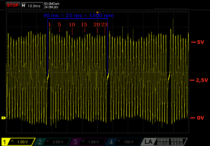
On the crankshaft there is a flywheel with teeth every 15 degree. Each tooth induces a pulse in a fixed pick up coil.
There are 24 positions on the 360 degree rotation. One of them is missing, so there are 23 pulses per rotation.
The gap from the missing tooth indicates the position near BDC (Bottom Dead Center) of cylinder 1.
Example: The motor runs with 1500 rpm. This is 1500 / 60 = 25 rotations per second = 40 ms per rotation.
This oscilloscope capture measured at ECU pin J2-04 shows the 25 * 23 = 575 pulses/second.
 |
| Show Full Size |
The faster the motor runs the higher becomes the voltage.
The logfile Benelli TRK 251 (1 Cylinder).xml shows several CKP Sensor Errors which are increasing with the time.
But they are still not enough to turn the MIL/EFI indicator light on.
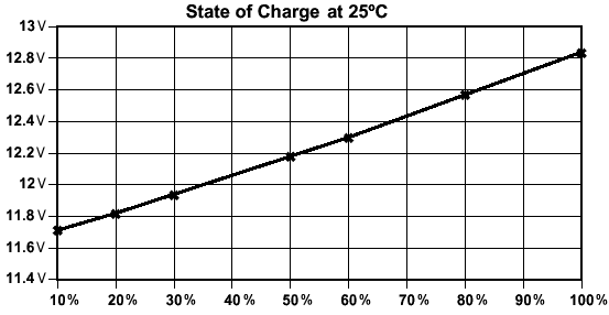
Battery
Lead-Acid batteries allow to easily detect their charge status by simply measuring the voltage while the ignition key is off.
At 12.8 Volt it is completely full.
Very detailed information about batteries can be found at the Battery University.
The lifetime of a motorbike battery is approx one year when used frequently.
When the voltage of the fully charged battery drops below 9 Volt while cranking the battery should be replaced.
If the alternator / generator works correctly the voltage should be between 13.5 and 14.5 Volt while the engine is running.
If the regulator is defective and the voltage rises to more than 15 Volt the battery will be damaged.