
Topic: I can’t get the board outline to gerber (Read 11905 times)
0 Members and 1 Guest are viewing this topic.
I can’t seem to find how to output the board outline in:
FILE — FABRICATION OUTPUTS — GERBER FILES — Drill drawing tab
Does anyone know how I can get the board outline in the gerber of the drill drawing.
I’m really wasting my day on this and have better things to do.
Thanks in advance,
Brian

Logged
draw the outline on a mechanical layer. in the project outputs create a ‘final’ project. there you can add the board outline to the plot.
Logged
Professional Electron Wrangler.
Any comments, or points of view expressed, are my own and not endorsed , induced or compensated by my employer(s).
I can’t seem to find how to output the board outline in:
FILE — FABRICATION OUTPUTS — GERBER FILES — Drill drawing tabDoes anyone know how I can get the board outline in the gerber of the drill drawing.
I’m really wasting my day on this and have better things to do.Thanks in advance,
Brian
I had the same problem, here you can consider the reason and solution.
https://www.eevblog.com/forum/altium-designer/altium-gerber-export-board-outline/
Logged
Free_Electron gave you the exact answer. Not knowing your level of experience with Altium, I’ll spell out the steps a bit more explicitly:
1. Use «Design->Board Shape->Create Primitives from Board Shape». Create the primitives in a mechanical layer, and make sure nothing else is in that layer.
2. You should be using an OutJob to create the Gerbers. Right click the «Gerbers» line, select config, go to the «layers» tab, and check the mechanical layer containing your outline.
3. Document your convention, including the name of the outline Gerber, in your README file.
Dave
« Last Edit: May 09, 2012, 01:39:14 pm by dfnr2 »
Logged
Here is another technique : i simply draw the outline on the keepout layer.
S-y. ( select all on layer )
Define board from selected objects.
Do design
In gerber. Export job , the keep out layer will automatically be injected as a separate plot.
If. You draw it on a mechanical layer , make sure the ‘add to plot’ is turned off, or it appears on every single gerber file. Board houses don’t like that as they have to remove it …
Logged
Professional Electron Wrangler.
Any comments, or points of view expressed, are my own and not endorsed , induced or compensated by my employer(s).
Thanks all. I finally figured this out after about four hours searching.
From now on I will put a copy of the board outline on the Drill Fabrication layer. That way I can get it on my gerber of the fab, but not on the other layers.
Brian
Logged
Contents
- Summary
- Availability
- Interactively Defining and Editing the Board Shape
- Defining the Board Shape from Selected Objects
- Board Shape Demonstration when using Standard Rigid-Flex Mode
- Board Shape Demonstration when using Advanced Rigid-Flex Mode
- Importing an Outline to Use for the Board Shape
- Defining the Board Shape from a 3D Body
- Creating Primitives from the Board Shape
- Cutting a Hole in the Board Shape
- Important Design Considerations When Using Board Cutouts
- Keeping a Polygon Back from the Edge of a Board Cutout
- Defining a Route Tool Path Around the Edge of the Board and Cutouts
- Important Design Considerations When Using Board Cutouts
- Keepouts and the Board Shape
All Contents
Parent page: Pre-layout Stage
There are two rigid-flex design modes available in Altium’s PCB design software. The original, or standard mode, referred to as Rigid-Flex, supports simple rigid-flex designs. If your design has more complex rigid-flex requirements, such as overlapping flex regions, then you need the Advanced Rigid-Flex mode (also known as rigid-flex 2.0). The mode is chosen in Tools menu in the Layer Stack Manager.
► Learn more about Rigid-Flex Design
The Board Shape defines the overall shape of the finished board. Click through the slides to see the three Board Regions that make up the rigid-flex shape, and the finished board in 3D.
Summary
The Board Shape, also referred to as the board outline, is a closed polygonal shape that defines the overall extents of the board. The Board Shape can be made up of a single Board Region (for a traditional rigid PCB) or multiple board regions (for a rigid-flex PCB). The Board Shape is used by the software for:
- Providing a visual guide of the extents of the space available for the placement and routing of the design.
- Power plane edge pullback, and edge references for splitting a power plane into separate voltage zones. Learn more about Defining and Managing Copper Areas.
- Calculating the board edge when outputting design data to other tools.
Availability
The Board Shape is only available in the PCB editor. When a new PCB file is created, it opens with a rectangular Board Shape created from a single Board Region.
The overall Board Shape can be created by:
- Interactively defining the Board Shape in Board Planning Mode.
- Creating the Board Shape from selected track/arc objects that form a closed boundary. If you are working in Advanced Rigid-Flex mode, then multiple Board Regions can be created from objects selected in the design space.
- For a Rigid-Flex design (Standard or Advanced Mode), the Board Shape can be sliced into the various Board Regions needed in the design.
- Placing one or more Board Regions to build up the overall Board Shape (Advanced Rigid-Flex mode).
The default Board Shape in a new PCB document is a rectangular shape (6 inch x 4 inch, or 6000mil x 4000mil, or 152.4mm x 101.6mm). For specific project templates that can be used when creating a new PCB project, the associated PCB document in each case has a specific Board Shape according to the form factor of the board.
The current viewing mode for the PCB document can be changed using the corresponding commands from the main View menu. Alternatively, change views quickly using the 1 (Board Planning Mode), 2 (2D) and 3 (3D) keyboard shortcuts.
Interactively Defining and Editing the Board Shape
The Board Shape is created from one or more Board Regions. For designers working on a single-region board design, the following commands can be used to define the Board Shape:
- Board Planning Mode (standard Rigid-Flex mode):
- Design » Redefine Board Shape — use this command to interactively redraw the current Board Shape.
- Design » Edit Board Shape — use this command to move and reshape the edges of the Board Shape, using standard polygonal object editing techniques.
- Board Planning Mode (Advanced Rigid-Flex mode):
- Place » Board Region — use this command to interactively define the Board Region (for a single-region board, the Board Region defines the Board Shape). Learn more about the Board Region object.
- 2D Layout Mode:
- Design » Board Shape » Define Board Shape from Selected Objects — select a set of line and/or arc primitives that define a closed shape then use this command to redefine the Board Shape to match the shape.
- Design » Board Shape » Create Primitives from Board Shape — create a set of primitives along the Board Shape boundary, in accordance with the settings configured in the Line/Arc Primitives from Board Shape dialog.
- 3D Layout Mode:
- Design » Board Shape » Define Board Shape from 3D body — use this command to define the Board Shape by selecting the desired surface of a 3D model.
Additionally, you can use the following commands when in Board Planning Mode:
- Design » Modify Board Shape — use this command to modify the existing board shape by placing additional vertex points, and so define additional shaping for the border.
- Design » Move Board Shape — use this command to move the board shape to another position in the current document. Only the board shape is moved using this command. The actual design and constituent objects remain unmoved.
- Design » Move Board — use this command to move the entire board — the board shape, plus all design objects within that shape — to another position in the current document.
- To interactively define (and edit) the Board Shape, switch to Board Planning Mode where you can place a Board Region. Learn more about placing and editing a Board Region.
- There are also a number of commands for working with Board Regions, learn more about the commands for converting between drawing primitives and board definition objects.
The difference between the Define Board Shape from Selected Objects command and the Create Board Region from Selected Objects command is that the first command replaces all existing Board Regions with the new region that is created when the command is run, whereas the second command creates an additional Board Region, without removing any existing Board Region(s).
Defining the Board Shape from Selected Objects
The Board Shape can also be defined from selected objects (in 2D Layout Mode). Typically this will be a set of lines and/or arcs placed on the Keepout layer or a mechanical layer.
Use the following sequence of steps:
- Set the View mode to 2D Layout Mode (View menu).
- Open the View Configuration panel and double-click to edit the mechanical layer that holds the board shape. The Edit Layer dialog will open, where you can set the Layer Type to
Board Shape, as shown in the video below. - Make the mechanical layer that holds the shape the active layer, and select the objects. The Edit » Select » All on Layer command is ideal for this; the selection set must only include the tracks and arcs that form the shape of the board outline.
- Once all the objects are selected, run the Design » Board Shape » Define Board Shape from Selected Objects command. The Board Shape will update to follow the path defined by the selected lines. A warning dialog will appear if the software is unable to follow the centerline of the selected objects. The View mode will change to Board Planning Mode.
Board Shape Demonstration when using Standard Rigid-Flex Mode
The video demonstrates creating the Board Shape from selected objects and then placing Split Lines to create the three regions needed.
Board Shape Demonstration when using Advanced Rigid-Flex Mode
The video first demonstrates creating the Board Shape from selected objects and then slicing the shape to create the three regions needed. Then it shows an alternate approach, where
the three Board Regions are defined from selected objects. Note that these demonstrations are using Rigid-Flex 2.0 features, as described at the start of this page.
The software will attempt to find the shape based on the centerline of the selected objects. If the coordinates for the end of one track/arc segment do not exactly match the coordinates of the next track/arc segment, the boundary identification algorithm will fail and a message will be displayed showing the failure location. It will offer to use a tracing algorithm instead. Note that the tracing algorithm follows the outer edge of the track/arc objects, so the Board Shape will be slightly different than the one created from the centerlines. Only choose this option if your design can accept the impact of this difference.
Importing an Outline to Use for the Board Shape
The Board Shape can be defined from a closed outline imported as DXF/DWG data.
By combining the ability to import DXF / DWG data into a mechanical layer and then defining the board shape from selected objects, a shape defined in a mechanical CAD package can be transferred into the PCB editor.
To prepare the new board for import:
- Select File » New » PCB. A new blank PCB will open; the black region represents the current Board Shape.
- Before importing a new shape, set the following as required to suit the requirements of your design and the shape being imported:
- The Units — set the units as required in the Other section of the Properties panel in Board mode (show image).
- The Grid — double-click on the Global Board Snap Grid and set it as required in the Grid Manager section of the Properties panel in Board mode (show image).
- The Origin — For a new PCB the default location for the user-definable origin is at the absolute origin, the bottom left of the design space. Select Edit » Origin » Set from the main menus then click to define the location of the user-definable origin, for example, the bottom left corner of the current board shape. It helps to set this to suit the location of the origin in the incoming outline.
The next step is to import the board’s shape as a .DXF or .DWG file. Note that the shape to be imported must be a closed shape and internal cutouts are not automatically created (but can be defined later from imported objects).
- Select File » Import » DXF/DWG to open the Import File dialog then ensure the File Type on the bottom right of the dialog is AutoCAD Files (*.DXF, *.DWG) then browse to find the required file.
- When the Open button is clicked the Import from AutoCAD dialog will open (show image).
- Set the Scale, Default Line Width and Layer Mappings as required then click OK.
- Each DXF/DWG object will be mapped to an object and will be displayed in the design space.
- Make the mechanical layer that holds the board shape objects the active layer, then select all objects on that layer (Edit » Select » All on Layer).
- To update the Board Shape to match the selected outline, run the Design » Board Shape » Define from Selected Objects command.
- If the board includes board cutouts, these can be created by selecting the outline of the cutout and running the Tools » Convert » Create Board Cutout from Selected Primitives command.
The software will attempt to find the shape based on the centerline of the selected objects. If the coordinates for the end of one track/arc segment do not exactly match the coordinates of the next track/arc segment then the boundary identification algorithm will fail and a message will be displayed showing the failure location. It will offer to use a tracing algorithm instead. Note that the tracing algorithm follows the outer edge of the track/arc objects so the board shape will be slightly different than the one created from the centerlines. Only choose this option if your design can accept the impact of this difference.
Defining the Board Shape from a 3D Body
This feature redefines the board shape based on a surface (face) of an imported 3D model. Supported model formats includes: STEP (*.Stp or *.STEP), Parasolid (*.x_t or *x_b), or a SOLIDWORKS Part File (*.SldPrt). It can be used to quickly create a complex board shape and helps integration between electronic and mechanical design areas. This is a two-stage process: first the STEP model is imported, then the required shape is selected from the STEP model.
Only a flat (planar) surface can be used to define the board shape.
To do this:
- Switch to View » 3D Layout Mode (shortcut: 3).
- To import the 3D model, place a 3D body (Place » 3D Body).
- In the Choose Model dialog, locate and select the model file. The 3D model will be imported into the PCB editor and stored inside a 3D Body object. Note that this model can be deleted from the PCB once the board shape has been redefined if required.
- Select Design » Board Shape » Define Board Shape from 3D body.
- The Status bar will prompt you to Pick a 3D body. Click the imported 3D body to select it. The model will become transparent.
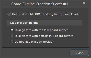
- The cursor will change to a crosshair and the Status bar will prompt you to Choose Face. As you hover the cursor over each face, it will be outlined. Where a flat surface is found under the cursor, it will become opaque with a thin blue border. Click to select the correct face.
- The Board Outline Creation Successful dialog will appear, displaying options for which PCB surface should align with the selected surface (typically the top layer), and if the 3D model should be hidden from view and design rule checking. The hide and disable behavior can be changed later if required, in the 3D Models mode of the PCB panel.
Note that if you keep the STEP model embedded in or linked to the PCB file, you will be notified whenever the STEP file changes. You will also be prompted to update the shape, which helps if the shape is still under development and updates are expected.
Only surfaces aligned with the X-Y plane can be used to create the board shape. If you select a model surface that requires alignment in the X-Y plane, you will be asked in a Confirm dialog to align the surface before you can continue. This dialog also allows you to place the model using the selected face in relation to either the top or bottom surface of the board. This means that the vertical position of the model can also be set at the same time. After alignment, you will need to select Design » Board Shape » Define from 3D Body again. After the board shape has been redefined, you will be given the option to hide the 3D body.
Creating Primitives from the Board Shape
As well as defining the Board Shape from selected primitives, it also is possible to create primitives from the Board Shape using the Design » Board Shape » Create Primitives from Board Shape command. This command will open the Line/Arc Primitives from Board dialog.

The Line/Arc Primitives From Board Shape dialog
- Width — specify the width of the generated Line/Arc primitives.
- Layer — choose a layer from drop-down list for the generated Line/Arc primitives.
- Include Cutouts — enable to include cutouts when generating outline primitives.
- Include layer stack regions — enable to include layer stack regions when generating outline primitives. A layer stack region is a user-defined area of a PCB that can have a unique layer stack assigned to it. A board can be split into multiple regions with each region assigned an individual layer stack arrangement. The layer stackups (defined in the Layer Stack Manager) can be configured to cater for both rigid and flexible regions of the board, facilitating rigid-flex PCB design. Layer stack regions can be browsed through the PCB panel configured in Layer Stack Regions mode.
- Route Tool Outline — the default behavior is to place the outline primitives so that their centerline is on the edge of the board shape. When this option is enabled the line/arc objects are instead placed so their edge touches the edge of the board shape and the edge of the cutout, as required for a route (rout) tool outline.
- Delete Existing Non-Net Lines/Arcs On Layer — enable to delete existing Lines/Arcs that are not associated with a specific net on the selected layer.
Use this command when the Board Shape exists but there are currently no objects along the boundary. Situations where this command can be useful include:
- When you want to modify the Board Shape (or board cutouts) by modifying track and arc primitives first.
-
When you need a keepout boundary for the board or keepout boundaries for board cutouts on the Keep-Out layer. This is discussed in more detail below in the Important Design Considerations When Using Board Cutouts section.
If the target layer is specified to be the Keep-Out layer, object specific keepout objects will be placed directly on the layer (keepout track and keepout arcs).
Cutting a Hole in the Board Shape
A board cutout can be placed anywhere in the Board Shape. To place a cutout, switch to view the board in 2D Layout Mode then use the Design » Board Shape » Define Board Cutout command from the main menus (alternatively, you can also use the Place » Define Board Cutout command in Board Planning Mode). Note that the cutout is actually a Region object configured to be a negative object.
 A Board Cutout has been placed on the Board Shape.
If the board cutout is an unusual shape, such as a circle, it can be easier to create an outline of the cutout shape using tracks and arcs (for example, Place » Arc » Full Circle), select the shape, and then convert it to a Board Cutout (Tools » Convert » Create Board Cutout from Selected Primitives).
Important Design Considerations When Using Board Cutouts
Keeping a Polygon Back from the Edge of a Board Cutout
Polygons that overlay a solid region board cutout will pour as close to the edge of the cutout as allowed by the applicable Clearance design rule. A specific Clearance design rule can be created if required, which could, for example, be scoped to apply between IsBoardCutoutRegion and InPolygon.
Defining a Route Tool Path Around the Edge of the Board and Cutouts
A common approach used to cut the finished board from the fabrication panel is to mill or route the board out of the panel. Board cutouts can also be routed out. A Route Tool path is defined by placing Line and/or Arc objects on a mechanical layer. This can be done manually or automatically by the software.
To define a Route Tool path for the board and any board cutouts:
- With the board in 2D Layout Mode, run the Design » Board Shape » Create Primitives From Board Shape command. The Line/Arc Primitives From Board Shape dialog will open.
- Define a suitable Width for the objects that will define the Rout Tool path. Consult with your fabricator if you are unsure of this.
- Select an available mechanical layer. This layer should be reserved for just the Rout Tool path definition.
- Enable the Include Cutouts option if the board has cutouts in it.
- Enable the Route Tool Outline option. When this option is enabled the line/arc objects are placed so their edge touches the edge of the Board Shape and the edge of the cutout.
- Click OK to create the Route Tool objects on the chosen mechanical layer.
- The mechanical layer used must be set as the Route Tool layer. To do this, access the Layers & Colors tab of the View Configuration panel. Right-click within a layers grid and choose the Add Mechanical Layer command. In the Edit Layer dialog that opens, set the Layer Type to Route Tool Path. This layer type is used to indicate the layer that contains the mechanical routing information. Note that a user-defined name is not permitted when the Layer Type is set to Route Tool Path. The reason for this is that older versions of the software use the name of the Route Tool Path layer to identify the layer that contains the route information (also referred to as rout information). Fixing the naming of this layer ensures that the design will continue to function correctly in an older version.
The images below show the Route Tool path defined on a mechanical layer.

 A Board Cutout in the first image, with a Route Tool path defined in the second image.
Keepouts and the Board Shape
As well as the Board Shape, you also should define a placement and routing boundary around the edge of the board. This can be created automatically from the Board Shape itself using the Design » Board Shape » Create Primitives From Board Shape command (in 2D Layout Mode), and setting the Layer in the Line/Arc Primitives from Board dialog to the Keep-Out Layer.
Alternatively, this can be done manually by placing objects on the keepout layer. Objects placed on this layer define a no-crossing-allowed boundary for components and routing. Typically you want objects such as components and routing to be a certain distance from the edge of the board; this distance can be controlled by setting the applicable routing and component placement design rules. You can also define other routing and component keepout areas for mechanical objects, such as screw heads or other mounting requirements.
 layer.") A keepout boundary defined by placing standard line objects on the keepout (purple) layer.
A keepout boundary defined by placing standard line objects on the keepout (purple) layer.
- Keepout boundaries can be defined by placing any standard design objects, such as lines, arcs, fills, and regions on the Keepout layer. Objects placed on the Keepout layer create a keepout on all signal layers.
- You also can define layer-specific keepouts on any copper layer. To do this:
- Click on the layer tab of the required layer.
- Define the boundary or area of the keepout area by placing layer-specific keepout objects (Place » Keepout submenu). Layer specific keepouts are standard objects with the Keepout attribute enabled. They are displayed in the same color as the layer with a keepout colored edge. Note that layer-specific keepout objects are not included in Gerber or ODB++ output files.
Skip to main content
![]()
![]()
Welcome to EDAboard.com
Welcome to our site! EDAboard.com is an international Electronics Discussion Forum focused on EDA software, circuits, schematics, books, theory, papers, asic, pld, 8051, DSP, Network, RF, Analog Design, PCB, Service Manuals… and a whole lot more! To participate you need to register. Registration is free. Click here to register now.
-
Hardware and PCB Design
-
PCB Routing Schematic Layout software and Simulation programs
You should upgrade or use an alternative browser.
Altium Designer: How to generate Gerber board outline?
-
Thread starterJohnG300c
-
Start dateJan 9, 2008
- Status
- Not open for further replies.
-
#1

- Joined
- Dec 5, 2006
- Messages
- 117
- Helped
- 2
- Reputation
-
4
- Reaction score
- 2
- Trophy points
- 1,298
- Activity points
-
2,228
I have not managed to automatically generate the board outline. Must I manually draw the board outline on one of the mechanica layers?
-
#2
fala
Full Member level 5

- Joined
- Sep 18, 2005
- Messages
- 249
- Helped
- 19
- Reputation
-
38
- Reaction score
- 4
- Trophy points
- 1,298
- Activity points
-
3,569
in PCB first choose Keep-Out Layer, then place >> line (it should be place in keep-out layer), draw your board outline. then select all the lines you drew to determine board outline(note that All the lines should have been selected ANDtheir end point should exactly overlap on the next lineANDaltogether they should be a closed shape then go to desgn>> redefine board shape>> define from selected objects. then generate gerber. if you do all the steps correctly you will get what you want.
cheers
-
#3

- Joined
- Feb 21, 2002
- Messages
- 1,369
- Helped
- 406
- Reputation
-
812
- Reaction score
- 97
- Trophy points
- 1,328
- Location
-
USA
- Activity points
-
16,416
When generating Gerber files, you have to select the layer that contains your board outline in the Gerber Setup Dialog. Unlike some other EDA programs, Altium Designer doesn’t have a special «Board Outline» layer. You either have to use your «Keepout Layer» or some other layer on which you’ve drawn your outline.
I like to use mechanical layer 3 for my board outline, other users have their own favourite layer they reserve for the outline. Note that you can rename the layer to «Board Outline» in the «Layers and Colors» dialog (shortcut «L»). However, the Gerber file output will still have the standard Altium Designer suffix.
The short answer to your question is — Yes, you have to have your board outline drawn on some layer, and use that layer to generate the Geber file for your board outline.
-
#4
- Joined
- Dec 5, 2006
- Messages
- 117
- Helped
- 2
- Reputation
-
4
- Reaction score
- 2
- Trophy points
- 1,298
- Activity points
-
2,228
Thanks Fala and House cat. I now have border outline gerbers.
- Status
- Not open for further replies.
Similar threads
-
Hardware and PCB Design
-
PCB Routing Schematic Layout software and Simulation programs
-
This site uses cookies to help personalise content, tailor your experience and to keep you logged in if you register.
By continuing to use this site, you are consenting to our use of cookies.