Построение кодов
Хемминга базируется на принципе проверки
на чётность веса W
(числа единичных символов) в информационной
группе кодового блока.
Поясним идею
проверки на чётность на примере
простейшего корректирующего кода,
который так и называется, кодом с
проверкой на чётность или кодом с
проверкой по паритету (равенству).
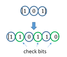
В таком коде к
кодовым комбинациям безызбыточного
первичного двоичного k-разрядного
кода добавляется один дополнительный
разряд (символ проверки на чётность,
называемый проверочным, или контрольным).
Если число символов «1» в исходной
кодовой комбинации чётное, то в
дополнительном разряде формируют
контрольный символ «0», а если число
символов «1» нечётное, то в дополнительном
разряде формируют символ «1». В результате
общее число символов «1» в любой
передаваемой кодовой комбинации всегда
будет чётным.
Таким образом,
правило формирования проверочного
символа cводится
к следующему:
r1
= i1
![]()
i2
![]()
. . .
![]()
ik,
где i
–
соответствующий информационный символ
(0 или 1); k –
общее их число, а под операцией
![]()
здесь и далее понимается сложение по
модулю 2.
Очевидно, что
добавление дополнительного разряда
увеличивает общее число возможных
комбинаций вдвое по сравнению с числом
комбинаций исходного первичного кода,
а условие чётности разделяет все
комбинации на разрешённые и неразрешённые.
Код с проверкой на чётность позволяет
обнаруживать одиночную ошибку при
приёме кодовой комбинации, так как такая
ошибка нарушает условие чётности,
переводя разрешённую комбинацию в
запрещённую.
Критерием
правильности принятой комбинации
является равенство нулю результата S
суммирования по модулю 2 всех n
символов кода, включая проверочный
символ ri.
При наличии одиночной ошибки S
принимает значение 1:
S = r1
![]()
i1
![]()
i2
![]()
. . .
![]()
ik
= 0
– ошибки
нет;
S
= r1
![]()
i1
![]()
i2
![]()
. . .
![]()
ik
= 1
– однократная ошибка.
Этот код является
(k + 1,
k)-кодом, или
(n, n — 1)-кодом.
Минимальное расстояние кода равно двум
(dmin
= 2), и,
следовательно, никакие ошибки не могут
быть исправлены. Простой код с проверкой
на чётность может использоваться только
для обнаружения (но не исправления)
однократных ошибок.
Увеличивая число
дополнительных проверочных разрядов
и формируя по определённым правилам
проверочные символы r,
равные 0 или 1, можно усилить корректирующие
свойства кода так, чтобы он позволял не
только обнаруживать, но и исправлять
ошибки. На этом и основано построение
кодов Хемминга.
Рассмотрим эти коды, позволяющие
исправлять одиночную ошибку, с помощью
непосредственного описания. Для каждого
числа проверочных символов r
= 3, 4, 5…
существует классический код Хемминга
с маркировкой
(n,
k)
= (2r
– 1,
2r
– 1
— r),
(4.24)
т. е. – (7,4),
(15,11), (31,26).
При других значениях
числа информационных символов k
получаются так
называемые усечённые
(укороченные) коды Хемминга. Так, для
международного телеграфного кода МТК-2,
имеющего 5 информационных символов,
потребуется использование корректирующего
кода (9,5), являющегося усечённым от
классического кода Хемминга (15,11), так
как число символов в этом коде уменьшается
(укорачивается) на 6. Для примера рассмотрим
классический код Хемминга (7,4), который
можно сформировать и описать с помощью
кодера, представленного на рис. 4.2.

Рис. 4.2
В простейшем
варианте при заданных четырёх (k
= 4) информационных
символах (i1,
i2,
i3,
i4)
будем полагать, что они сгруппированы
в начале кодового слова, хотя это и не
обязательно. Дополним эти информационные
символы тремя проверочными символами
(r
= 3), задавая их следующими равенствами
проверки на чётность, которые определяются
соответствующими алгоритмами
r1
= i1
![]()
i2
![]()
i3;
r2
= i2
![]()
i3
![]()
i4;
r3
= i1
![]()
i2
![]()
i4,
где знак «![]() »
»
означает сложение по модулю 2.
На рис. 4.3 приведена
схема декодера для (7,4)-кода Хемминга,
на вход которого поступает кодовое
слово:
V =
(i′1,
i′2,
i′3,
i′4
,
r′1,
r′2,
r
′3).
Апостроф означает,
что любой символ слова может быть искажён
помехой в канале передачи.

Рис. 4.3
В декодере, в режиме
исправления ошибок, строится
последовательность:
s1
= r1’
![]()
i1’
![]()
i2’
![]()
i3’;
s2
= r2’
![]()
i2’
![]()
i3’
![]()
i4’;
s3
= r3’
![]()
i1’
![]()
i2’
![]()
i4’.
Трёхсимвольная
последовательность (s1,
s2,
s3)
называется синдромом. Термин «синдром»
используется и в медицине, где он
обозначает сочетание признаков,
характерных для определённого заболевания.
В данном случае синдром S
= (s1,
s2,
s3)
представляет собой сочетание результатов
проверки на чётность соответствующих
символов кодовой группы и характеризует
определённую конфигурацию ошибок
(шумовой вектор).
Кодовые слова кода
Хемминга для k
= 4 и r
= 3 приведены в табл. 4.1.
Число возможных
синдромов определяется выражением
S = 2r.
(4.25)
При числе проверочных
символов r
= 3, имеется восемь возможных синдромов
(23
= 8). Нулевой синдром (000) указывает на то,
что ошибки при приёме отсутствуют или
не обнаружены. Всякому ненулевому
синдрому соответствует определённая
конфигурация ошибок, которая и
исправляется. Классические коды Хемминга
(4.20) имеют число синдромов, точно равное
их необходимому числу, позволяют
исправить все однократные ошибки в
любом информативном и проверочном
символах и включают один нулевой синдром.
Такие коды называются плотноупакованными.
Таблица 4.1
|
k |
r |
|||||
|
i1 |
i2 |
i3 |
i4 |
r1 |
r2 |
r3 |
|
0 |
0 |
0 |
0 |
0 |
0 |
0 |
|
0 |
0 |
0 |
1 |
0 |
1 |
1 |
|
0 |
0 |
1 |
0 |
1 |
1 |
0 |
|
0 |
0 |
1 |
1 |
1 |
0 |
1 |
|
0 |
1 |
0 |
0 |
1 |
1 |
1 |
|
0 |
1 |
0 |
1 |
1 |
0 |
0 |
|
0 |
1 |
1 |
0 |
0 |
0 |
1 |
|
0 |
1 |
1 |
1 |
0 |
1 |
0 |
|
1 |
0 |
0 |
0 |
1 |
0 |
1 |
|
1 |
0 |
0 |
1 |
1 |
1 |
0 |
|
1 |
0 |
1 |
0 |
0 |
1 |
1 |
|
1 |
0 |
1 |
1 |
0 |
0 |
0 |
|
1 |
1 |
0 |
0 |
0 |
1 |
0 |
|
1 |
1 |
0 |
1 |
0 |
0 |
1 |
|
1 |
1 |
1 |
1 |
1 |
0 |
0 |
|
1 |
1 |
1 |
1 |
1 |
1 |
1 |
Усечённые коды
являются неплотноупакованными, так как
число синдромов у них превышает
необходимое. Так, в коде (9,5) при четырёх
проверочных символах число синдромов
будет равно 24
= 16, в то время как необходимо всего 10.
Лишние 6 синдромов свидетельствуют о
неполной упаковке кода (9,5).
Для рассматриваемого
кода (7,4) в табл. 4.2 представлены ненулевые
синдромы и соответствующие конфигурации
ошибок.
Таблица 4.2
|
Синдром |
001 |
010 |
011 |
100 |
101 |
110 |
111 |
|
Конфигурация |
0000001 |
0000010 |
0001000 |
0000100 |
1000000 |
0010000 |
0100000 |
|
Ошибка |
r3 |
r2 |
i4 |
r1 |
i1 |
i3 |
i2 |
Таким образом, код
(7,4) позволяет исправить все одиночные
ошибки. Простая проверка показывает,
что каждая из ошибок имеет свой
единственный синдром. При этом возможно
создание такого цифрового корректора
ошибок (дешифратора синдрома), который
по соответствующему синдрому исправляет
соответствующий символ в принятой
кодовой группе. После внесения исправления
проверочные символы
ri
можно на выход декодера не выводить.
Две или более
ошибки превышают возможности
корректирующего кода Хемминга, и декодер
будет ошибаться. Это означает, что он
будет вносить неправильные исправления
и выдавать искажённые информационные
символы.
Идея построения
подобного корректирующего кода,
естественно, не меняется при перестановке
позиций символов в кодовых словах. Все
такие варианты также называются (7,4) –
кодами Хемминга.
Соседние файлы в предмете [НЕСОРТИРОВАННОЕ]
- #
- #
- #
- #
- #
- #
- #
- #
- #
- #
- #
Изобретение относится к вычислительной технике, в частности к устройствам обнаружения и исправления ошибок, возникающих при хранении или передаче цифровой информации. Целью изобретения является повышение быстродействия устройства . Указанная цель достигается путем устранения избыточной коррекции, контрольных символов за счет введения в корректор блока селекции ошибок контрольных символов с информацией, указывающей, в каком месте кодового слова — в поле информационных или в поле контрольных символов произошла ошибка. Корректор ошибок содержит синдромный регистр, блок обратной связи, детектор ошибки, блок фиксации местоположения ошибки, буфер данных, блок коррекции ошибки, блок управления и блок селекции ошибок контрольных символов . 2 ил. С/)
СОЮЗ СОВЕТСКИХ
СОЦИАЛИСТИЧЕСКИХ
РЕСПУБЛИК (я)5 G 11 С 29/00
ГОСУДАРСТВЕННОЕ ПАТЕНТНОЕ
ВЕДОМСТВО СССР (ГОСПАТЕНТ СССР) ОПИСАНИЕ ИЗОБРЕТЕНИЯ
К АВТОРСКОМУ СВИДЕТЕЛ ЬСТВУ (21) 4761070/24 (22) 21,11.89 (46) 23.04.93. Бюл. N 15 (71) Институт кибернетики им, В.М.Глушкова (72) В.В.Звягинцев (56) Кларк Дж., Кейн Дж. Кодирование с исправлением ошибок в системах цифровой связи. — M.: Радио и связь, 1987, с. 71-85, Блейхут P. Теория и практика кодов, контролирующих ошибки, — M.: Мир, 1986, с, 174. (54) КОРРЕКТОР ОШИБОК (57) Изобретение относится к вычислительной технике, в частности к устройствам обнаружения и исправления ошибок, возникающих при хранении или передаче
Настоящее изобретение относится к области вычислительной техники; в частности, к устройствам обнаружения и исправления ошибок, возникающих при хранении или передаче цифровой информации.
В настоящее время в вычислительной. технике при кодировании информации ши.рокое применение получили циклические коды — коды Хэмминга, Файра и др. Помехоустойчивость указанных кодов обеспечивается за счет. введения избыточности, достигаемой посредством добавления так .называемых проверочных или контрольных символов к информационным символам кодируемого сообщения. В процессе кодирования исходное сообщение разбивается на информационные слова v
СО мационного слова по определенному алго-: ритму формируются. контрольные символы
Укон р. После присоединения контрольных символов к информационному слову получа-: ется кодовое слово чк0д циклического блокового систематического (n, k) — кода; где п — Р общее количество символов в кодовом слове, k — количество информационных симво-; ° лов: m = n — k — количество контрольных символов. При этом часто пользуются пол- иноминальным представлением кодовых векторов, что позволяет задавать циклический код математически с помощью так называемых порождающих многочленов. Например, порождающий многочлен У=х +х+1 над полем символов алфавита GF2 задает(31, 26) — код Хэмминга, исправляющий одну случайную ошибку.
1810909
Формирование контрольных символов в процессе кодирования осуществляется путем вычисления остаточного многочлена чконтр = чинф. х modY с испол ьзованием арифметики полей Галуа. При приеме сообщения осуществляют его декодирование с целью обнаружения и исправления ошибок, возникающих при хранении или передаче, Принятое слово может быть представлено в . виде суммы передаваемого кодового слова чк д и вектора ошибки vp . Вычисление при декодировании остаточного многочлена нконтр = (чкод+ чош) х mod Y позволЯет пол учить контрольные символы вектора ошибки, называемые синдромом. Располагая известным значением синдрома, можно, используя специальные устройства, называемые декодерами или корректорами ошибок, сформировать вектор ошибки и воссоздать в первоначальном виде переданное кодовое слово.
Известно устройство для коррекции независимых ошибок (см.Питерсон У., Уэлдон
Э. Коды. исправляющие ошибки, — М,: Мир, 1976, с. 191). Для этого корректора характерно недостаточное быстродействие, что обусловлено потерями времени на коррекцию кодовых слов, у которых искажены контрольные символы, Этот же недостаток присущ и корректору пачек ошибок (см.Портной С.А., Анкудинов Д.P. Кодеки корректирующих блочных кодов, — Зарубежная радиоэлектроника, 1985, N. 7, с. 3 — 27).
Известен корректор ошибок с неалгебраическим последовательным декодированием символов циклического систематического кода, в частности кода
Хэмминга (см,Блейхут P., Теория и практика кодов, контролирующих ошибки. — М,; Мир, 1986, стр. 174). Это устройство выбрано в качестве прототипа.
Схема прототипа приведена на фиг. 1.
Она содержит синдромный регистр 1, блок обратной связи 2, детектор ошибки 3. блок фиксации местоположения ошибки 4, буфер данных 5, блок коррекции ошибки 6 и блок управления 7; выход блока обратной связи
2 соединен с информационным входом синдромного регистра 1, выходы которого соединены с соответствующими информационными входами детектора ошибки 3 и блока фиксации местоположения ошибки 4, выход которого соединен со входами коррекции блока обратной связи 2 и блока коррекции ошибки 6, выход которого подключен к выходу 17 устройства и является информационным выходом корректора ошибок, выход детектора ошибки 3 подключен к выходу 16 устройства и является управляющим выходом корректора ошибок, информационные входы блока обратной связи 2; буфера данных 5 и первый информационный вход блока коррекции ошибки 6 объединены и подключены к входу
8 устройства, являющемуся информационным входом корректора ошибок, управляющие входы блока фиксации местоположения ошибки 4, детектора ошибки 3, блока коррекции ошибки 6 и блока обратной связи 2 подключены к управляющему выходу регистра синдрома 1, входы сброса и сдвига которого соединены соответственно с первым и вторым выходами блока управления 7, третий выход которого соединен с входом разрешения работы блока фиксации местоположения ошибки 4, второй информационный вход блока коррекции ошибки 6 соединен с выходом буфера данных 5, адресные входы и входы чтения, записи, обращения которого соединены соответственно с четвертым, пятым, шестым и седьмым выходами блока управления 7, восьмой, девятый и десятый выходы которого подключены к выходам 14, 15, 13 устройства и являются соответственно выходом синхронизации источника информации, выходом синхронизации приемника информации и выходом готовности корректора ошибок, входы начальной установки, сброса ошибки, чтения и коррекции блока управления 7 подключены к входам 9, 10, 11, 12 устройства и являются соответственно входом начальной установки, входом сброса ошибки, входом чтения и входом коррекции корректора ошибок.
Синдромный регистр 1 при приеме сообщений обеспечивает формирование контрольных символов (синдрома) кодового слова, поступающего с входа 8 устройства на информационный вход блока 2 обратной связи и с выхода последнего — на информационный вход регистра 1. Формирование синдрома осуществляется посредством посимвольного деления кодового слова qa по,рождающий многочлен. Прием и деление кодового слова на порождающий многочлен начинается с его,старших символов, Остатки от деления отдельных символов накапливаются в синдромном регистре 1, Окончательный результат получается после приема последнего (младшего) символа кодового слова. При обнаружении ошибки и принятом сообщении (синдром не равен нулю) регистр 1 и содержащийся в нем синдром используются для построения вектора
1810909 ошибки. Это осуществляется посредством модульного умножения синдрома. что обес печивается сдвигом вправо регистра синдрома 1. Сдвиг и сброс синдромного регистра
1 производится сигналами из блока управления 7, поступающими на входы сдвига и сброса регистра 1.
Блок 2 обратной связи обеспечивает формирование входных сигналов для синд. ромного регистра 1, используя для этого символы кодового слова, поступающие с входа 8 устройства, а также выходные.сигналы (сигналы обратной связи), освобождающиеся при сдвиге старшего разряда синдромного регистра 1. При этом в зависимости от значения сигнала на выходе блока фиксации местоположения ошибки 4, блок
2 разрешает или запрещает прохождение сигналов обратной связи на информационный вход регистра 1.
Детектор ошибки 3 вырабатывает сигнал «1», если содержимое синдромного регистра 1 не равно О. В режиме чтения это свидетельствует. о присутствии обнаруживаемых ошибок, а в режиме коррекции— неисправимых ошибок в принятом сообщении. Блок фиксации местоположения ошибки 4 в режиме коррекции вырабатывает выходной сигнал в момент завершения формирования синдромным регистром 1 вектора ошибки. Сигнал коррекции с выхода блока 4 поступает в блоки 6 и 2 для коррекции обнаруженной ошибки и соответствующего ей синдрома.
Буфер данных 5 предназначен для вре.менного. хранения принятого кодового слова на случай, если в дальнейшем потребуется исправление ошибок.
В блоке коррекции ошибки 6 происходит непосредственное исправление ошибок принятого кодового слова путем его посимвольного сложения (в случае двоичных кодов — по модулю два) с вектором ошибки, Блок управления 7 обеспечивает взаимодействие и синхронизацию работы узлов устройства. Блок 7 формирует сигналы сброса и сдвига синдромного регистра 1, сигнал управления блоком фиксации местоположения ошибки 4, сигналы записи. чтения, обращения, а также адресные сигналы буфера данных 5; сигналы готовности устройства, синхронизации источника и приемника информации.
Устройство-прототип работает следующим образом. Перед чтением в блок управления 7-от приемника информации через входы 9″ и 10 корректора ошибок поступают сигналы начальной установки устройства и сброса ошибки, осуществляющее сброс синдромного регистра 1 и подготовку к работе блока управления. Затем на вход 11 устройства приемник информации подает сигнал чтения и блок управления сбрасывает сигнал готовности на выходе 13 устройства и формирует последовательность сигналов синхронизации, которые с выхода
14 поступают к источнику кодированных со»0 общений. 3а одну команду чтения обеспечивается прием одного кодового слова. В ответ на каждый синхросигнэл источник сообщений передает один символ, Эти симво.лы ccr âxoäà 8 корректора ошибок без изменений через блок коррекции ошибок 6 поступают на информационный выход 17 и далее — к приемнику информации в сопровождении сигналов синхронизации на выхо20 де 15 устройства, Одновременно принимаемые символы записываются в буфер данных 5 и поступают в блок обратной связи 2 для деления на порождающий многочлен, После приема очередного символа блок управления 7 сдвигает вправо на.один разряд синдромный регистр 1 и инкрементирует на 1 код адреса на адресных входах буфера данных 5. Таким образом s процессе последовательного посимвольного деления принятого кодового слова в регистре 1 накапливаются частичные остатки от деления всех символов кодового слова, образую щие в конечном итоге умножений на х синдром ошибки S = (шкод+ ош) х п обУ.
35 После приема всех и символов кодового слова блок управления 7 останавливается и выдает на выход 13 устройства сигнал готовности. Если содержимое синдромного регистра 1 в этот момент не будет равно О, 40 то детектор ошибки 3 сформирует сигнал ошибки, который поступит на выход 16 устройства. Восприняв сигнал готовности корректора ошибок, приемник информации анализирует значение сигнала ошибки на выходе 16 корректора ошибок, Если сигнал ошибки отсутствует, то чтение кодового слова закончено. и приемник информации выдает вышеописанную последовательность команд для чтения следующего кодового слова, При наличии сигнала ошибки работа . устройства по декодированию принятого кодового слова должна быть продолжена с целью осуществления коррекции ошибоч55 ных символов. Для этого от приемника информации на входы 9 и 12 устройства подаются сигналы начальной установки и коррекции. Блок управления 7 при этом разрешает работу блока фиксации местоположения ошибки 4, переводит буфер данных 5
s режим чтения и сбрасывает сигнал готовности. Затем блок управления 7 формирует сигналы обращения к буферу данных 5, сдвига синдромного регистра 1, инкрементирования кода адреса на адресных входах буфера данных. Считываемое из буфера данных 5 искаженное кодовое слово посимвольно поступает в блок коррекции ошибки
6 и при отсутствии сигнала на выходе блока фиксации местополо>кения ошибки 4 без изменений передается через блок 6 на выход
17 устройства. Выдаваемые сигналы сопровождаются сигналами синхронизации на выходе 15 устройства. Одновременно с выдачей очередного символа сдвигается на один разряд вправо синдромный регистр 1 для умножения на х содер>кащегося в нем синдрома, После того, как в процессе последовательного умножения синдрома в регистре 1 будет сформирован вектор ошибки, блок 4 вырабатывает выходной сигнал, который поступит на вход коррекции блока 2 и разорвет обратную связь синдромного регистра 1, обеспечивая тем самым сохранность остающихся в нем при последующих сдвигах символов вектора ошибки. Этот же сигнал поступит на вход коррекции блока 6 и разрешит передачу вектора ошибки с управляющего выхода синдромного регистра
1 в блок 6. В блоке 6 происходит сложение искаженных символов кодового, слова, поступающих из буфера данных 5..-с символами вектора ошибки. Исправленные таким образом символы кодового слова с выхода
17 и сопровождающие их сигналы синхронизации с выхода 15 корректора ошибок поступают в приемник информации. После окончания передачи исправленного сообщения блок управления 7 останавливается и выдает на выход 13 устройства сигнал готовности. Если процесс исправления ошибок прошел успешно, то на выходе 16 устройства в этот момент будет отсутствовать сигнал ошибки. В противном случае, а это бывает при обнаружении неисправимых ошибок. на выходе 16 устройства будет присутствовать сигнал ошибки, и уже дело приемника информации решать, что делать в этом случае — оперировать и искаженной информацией, осуществить повторное чтение кодового слова или вообще прекратить дальнейшую рабату.
Устройству-прототипу присущ недостаток, заключающийся в недостаточном быстродействии. что обусловлено затратами времени на коррекцию контрольных символов. В большинстве случаев коррекция указанных символов не является необходимой, так как в дальнейшем при обработке информации в вычислительном устройстве они все равно не используются.
Целью настоящего изобретения является повышение быстродействия корректора ошибок за счет устранения избыточной коррекции контрольных символов. Технически это достигается путем введения в корректор ошибок блока селекции ошибок контрольных символов, информационные входы ко-. торого соединены с выходами синдромного регистра, а управляющий вход — с выходом узла управления; выход введенного в корректор ошибок блока является управляющим выходом устройства.
В известных корректорах ошибок повы.шение быстродействия достигается за счет использования более быстродействующей элементной базы, позволяющей увеличить скорость передачи информации при коррекции. Однако в этом случае быстродействие корректора ограничено пропускной способностью линий связи, а также временем вы- . борки информации из буфера данных, В.отличие от известных технических решений в предлагаемом устройстве за счет признаков, указанных в отличительной части формулы, устройству придается качественно новое свойство, а именно: устраняется избыточная коррекция контрольных символов. Следовательно этот признак является существенным.
Предлагаемое устройство изображено
35 на фиг. 2, Оно .содержит синдромный регйстр 1, включающий одноразрядные сдвигающие регистры 2, связанные через схемы.
3 сложения по модулю два, и ключи 4 задания коэффициентов порождающего много40 члена, блок обратной связи 5, детектор ошибки 9, блок фиксации местоположения ошибки 10, буфер данных 11, блок коррекции ошибки 12, блок селекции ошибок контрольных символов 16 и блок управления 17;
45 выход блока обратной связи 5 соединен с информационным входом синромного регистра 1, выходы которого соединены с соответствующими информационными входами детектора ошибки 9, блока селекции ошибок контрольных символов 16 и блока фиксации местоположения ошибки 10, выход которого соединен со входом коррекции блока обратной связи 5 и блока коррекции ошибки 12, 55 выход которого подключен к выходу 27 устройства и является информационным выходом корректора ошибок, выход детектора ошибки 9 соединен с выходом 26 устройства и является первым управляющим выходом корректора ошибок, информационные вхо1810909
10 ды блока обратной связи 5. буфера данных
11 и первый информационной вход блока коррекции ошибки 12 обьединены и подключены к входу 18 устройства, являющемуся информационным входом корректора ошибок, управляющие входы блока фиксации местоположения ошибки 10, детектора ошибки 9, блока коррекции ошибки 12 и блока обратной связи 5 подключены к управляющему выходу регистра синдрома 1, входы сброса и сдвига которого соединены соответственно с первым и вторым выходами блока управления 17, третий выход которого соединен с входом разрешения работы блока фиксации местоположения ошибки
10, второй информационный вход блока коррекции ошибки 12 соединен с выходом буфера данных 11. адресные входы и входы чтения, записи, обращения которого соединены соответственно с четвертым, пятым, шестым и седьмым выходами блока управления 17, восьмой, девятый и десятый выходы которого подключены к выходам 24, 25, 23 устройства и являются соответственно выходом синхронизации источника информации, выходом синхронизации приемника информации и выходом готовности корректора ошибок, входы начальной установки, . сброса ошибки, чтения и коррекции блока управления 17 подключены к входам 19, 20, 21, 22 устройства и являются соответственно входом начальной установки, входоM сброса ошибки, входом чтения и входом коррекции корректора ошибок, одиннадцатый выход блока управления 17 соединен с управляющим входом блока селекции ошибок контрольных символов 16, выход которого подключен к выходу 28 устройства и является вторым управляющим выходом корректора ошибок.
Сдвигающие регистры 2, схемы 3 сложения по модулю два и ключи 4 задания коэффициентов многочлена, порождающего циклический код, образуют синдромный регистр 1. Этот регистр при приеме сообщений обеспечивает формирование контрольных символов (синдрома) кодового слова, поступающего с выхода блока 5 на информационный вход регистра 1. Формирование синдрома осуществляется путем посимвольного деления на порождающий многочлен кодового слова, начиная с его старших символов, Остатки от деления отдельных символов накапливаются в синдромном регистре 1. Окончательный результат получается после приема последнего (младшего) символа кодового слова. При обнаружении ошибки в принятом сообщении (синдром не равен нулю) регистр 1 и содержащийся в нем синдром используются для построения вектора ошибки, которое осуществляется посредством модульного умножения синдрома при сдвигах вправо регистра синдрома 1. Сдвиг и сброс регистра 1 производится сигналами, поступающими из блока управления 17, В случае двоичных циклических кодов для полиномиального представления порождающего многочлена и кодового слова в виде
O х используется алфавит из двух
i=O символов — «0» и «1». Соответственно коэффициенты ai многочлена также могут. принимать только два указанных значения.
Например, синдромный регистр для декодирования циклического кода, заданного порождающим многочленом Y = х + х 1 =
5, 15
i а х, а =- а1 = а5 = 1, 82= аз = а4 = О, i =0 ных информационных сигналов для синдромного регистра 1, используя для этого входные информационные сигналы корректора ошибок, поступающие. на вход 18 от источника сообщений, а также сигналы обсодержит 5 одноразрядных сдвигаюьцих регистров, причем в замкнутом положении находятся только два крайних слева ключа, 30 задающих коэффициенты а и а>. Если коэффициенты Bl постоянны, то ключи 4 могут быть фиксированными (запаянными) связями. Выходами синдромного регистра 1 являются выходы входящих в его состав сдвигающих регистров 2. Сигнал с выхода старшего — крайнего справа разряда (управляющий выход) через блок 5 участвует в выработке . сигналов обратной связи синдромного регистра 1, Блок 5 обратной связи содержит двухвходовую схему И7, инвертор 6 и двухвходовую схему сложения по модулю два 8, Блок имеет 3 входа и 1 выход. Вход инвертора 6 является входом коррекции блока 5, Один из
45 входов схемы И7 соединен с управляющим выходом синдромного регистра 1 и является управляющим входом блока 5. Информационным входом блока 5 является вход схемы
8 сложения по модулю два, соединенный с
50 информационным входом l8 устройства, Выход схемы 8 сложения по модулю два— он же выход блока 5 соединен с информационным входом синдромного регистра 1.
Блок 5 обеспечивает формирование вход1810909 ратной связи, поступающие с управляющего выхода синдромного регистра 1. При этом в зависимости от значения сигнала на выходе блока 10 блок 5 будет разрешать или запрещать прохождение сигналов обратной связи на информационный входсиндромного регистра.
Детектор ошибки 9 представляет собой схему И вЂ” НЕ числом входов, равным количеству разрядов синдромного регистра 1.
При наличии ошибок в принятом кодовом слое содержимое регистра синдрома 1 не будет равно 0 и детектор ошибки сформирует «1» на своем выходе, который является первым управляющим выходом устройства.
В противном случае содержимое регистра синдрома 1 и выходной сигнал детектора ошибки будут равны О.
Блок фиксации местоположения ошибки 10 представляет собой схему И с количеством входов, обеспечивающим ее подключение ко всем выходам регистра синдрома 1, а также к выходу блока управления 17, разрешающему работу блока 10 в режиме коррекции. Блок 10 вырабатывает сигнал в момент завершейия формирования синдромным регистром 1 вектора ошибки.
Этот сигнал поступает в блоки 5, 12 для коррекции обнаруженной ошибки и соответствующего ей синдрома.
Буферданных11 предназначен для временного хранения принятого в режиме чтения кодового слова на случай, если в дальнейшем потребуется коррекция ошибок, В качестве буфера данных удобнее всего испол ьзовать последовательный сдвигающий регистр. Однако, ввиду того, что сдвигающие регистры большей разрядности промышленностью не выпускаются, в качестве буфера данных чаще всего используют одноразрядные ЗУ с прямой выборкой.
Адресные сигналы, сигналы чтения, записи и обращения к буферу данных формируются в блоке управления 17, В блоке коррекции ошибки 12 проихсодит непосредственное исправление ошибок принятого кодового слова путем его посимвольного сложения (в случае двоичных кодов — по модулю два) с веткаром ошибки. Блок 12 содержит двухходовую схему И 13, двухвходовую схему сложения по модулю два 14 и двухвходовую схему ИЛИ 15, Первый вход схемы И 13 соединен с выходом блока 10 и является одновременно входом коррекции блока 12. Второй вход схемы И13, связанный с управляющим выходом синдромного регистра 1, является управляющим входом блока
12, Первым информационным входом блока
12 является вход схемы ИЛИ 15. соединенный с информационным входом 18 корректора ошибок. Второй информационный вход блока 12 образует вход схемы сложения по модулю два 14, соединенный с выходом буфера данных 11, Выход схемы ИЛИ
15 является одновременно выходом блока
12, Блок селекции ошибок контрольных символов 16, являющийся отличительным признаком предлагаемого устройства, предназначен для выделения ошибок контрольных символов из всей совокупности ошибок кодового слова. Информационные входы блока 16 соединены с выходами регистра синдрома 1, а управляющий вход, разрешающий работу блока 16 в режиме чтения, — с выходом блока управления 17.
Выход блока 16 является одновременно вторым, управляющим выходом устройства.
Сигнал «1» на .этом выходе формируется, если в принятом кодовом слове ошибочными являются контрольные символы; в про25 тивном случае формируется сигнал «0».
Блок селекции ошибок контрольных символов может быть реализован на комбинационных логических схемах, на базе арифметико-логического устройства или
30 ПЗУ. Ниже рассмотрен пример реализации блока 16 на основе ПЗУ. Для представления информации об ошибках контрольных символов в ПЗУ достаточно одного бита на ошибку: «1» может быть использована для
35 кодирования ошибок контрольных символов, а «0» — для кодирования всех других ошибок. В случае например (31, 26) — кода
Хэмминга с пооождающим многочленом
Y = х +х+1 из 2 = 32 возможных значений
40 синдрома только пять следующих: x+1, х + . х +х, х +х, х +х+1 будут являться синдро3 4 3 мами ошибок контоольных символов, умно женными на х . Им соответствуют
5-разрядные адреса ПЗУ: 00011, 00110, 01100, 11000, 10011. По этим адресам в ПЗУ надо записать «1», а по остальным — «0».
Если при чтении содержимого ПЗУ перед коррекцией в качестве источника адреса использовать синдромный регистр, то можно получить информацию о характере ошибки.
Если при чтении будет получена «1», то ошибка принадлежит к-контрольным символам. Чтение информации из ПЗУ инициируется сигналом блока управления, поступающим на управляющий вход (вход разрешения обращения) ПЗУ, Выпускаемые в настоящее время БИС
ПЗУ, в частности серии 556 емкостью 1К—
64 К бит в одном корпусе, позволяют созда13 1810909 вать корректоры ошибок, оперирующие с кодовыми словами любой длины.
Блок управления 17 обеспечивает взаимодействие и синхронизацию работы узлов устройства. Схема блока управления приведена на фиг. 3, Она включает RS-триггеры
12, 13, 29; генератор тактовых импульсов 15; схемы ИЛ И 16, 24. 41, 42; схемы И 17, 23, 31, 32, 37, 38; инверторы l8, 33, 35; D-триггеры
26,28: схему ИЛИ-Н Е 27, схемы задержки 39, 40; счетчик тактовых импульсов 44, усилители 14, 25, 30, 34, 36, 43; вход усилителя 14
10 соединен с входом 19 начальной установки устройства, а выход — со входами сброса триггеров 12, 13, 26, 28, счетчика тактовых импульсов 44, а также с первым входом схемы ИЛИ 24; вход усилителя 25 соединен с входом 20 сброса ошибки устройства, а выход — с выходом 1 блока управления. Входы установки в «1» триггеров 12, 13 соединены соответственно со входами 21, 22 чтения и коррекции устройства, выход триггера 12 соединен с первыми входами схемы ИЛИ 16 и схем И 23, 38, а также с выходом 6 блока управления; выход триггера 13 соединен со вторым входом схемы ИЛИ 16 и с первыми входами схем И 17, 37, а также через усилители 30,36 — с выходами 5, 3 блока управления, выход генератора тактовых импульсов 15 соединен с тактовым входом D-триггера 26 и с первыми входами схем И 31, 32, информационный вход Dтриггера 26 соединен с выходом схемы ИЛИ
16, а выход — с вторым входом схемы И 31, третий вход которой соединен с выходом схемы ИЛИ вЂ” НЕ 27, выход схемы И 17 соединен с входом инвертора 18 и с первым входом схемы ИЛИ-НЕ 27, выход схемы И
23 соединен с информационным входом Dтриггера 28, и с вторыми входами схемы
ИЛИ вЂ” НЕ 27 и схемы И 32, третий вход которой соединен с выходом 0-триггера 28, а выход — с тактовыми входом D-триггера 28, 4 входом инвертора 33 и с выходом
11 блока управления. выход схемы
И 31 соединен со вторыми входами схем И 37, 38 и с входом инвертора 35; второй и третий входы схемы ИЛИ 24 соединены с выходами инверторов 18, 33; входы сброса и установки триггера 29 соединены с выходами схемы ИЛИ 24 и инвертора 35, а выход — через усилитель 34 подключен к выхоДу 10 блока управления и к выходу готовности 23 устройства. Выход схемы И 37 соединен с первым входом схемы ИЛИ 41 и через схему задержки 40- с первым входом схемы ИЛИ 42; выход схемы И 38 соединен с выходом 8 блока управления и с выходом
24 синхронизации источника информации устройства. а также через схему задержки
39 — со вторым входами схем ИЛИ 41, 42; выход схемы ИЛИ 41 соединен со счетным входом счетчика 44, и с выходом 7 блока управления; выход схемы ИЛИ 42 подключен к выходу 2 блока. управления. а также через усилитель 43; к выходу 9 блока управления и к выходу 25 синхронизации приемника информации устройства, информационные входы счетчика 44 соединены со вторыми входами схем И 17, 23 и с выходом 4 блока управления.
Блок управления работает следующим образом. Сигналами, поступающими от приемника информации на входы 19> 20, производится сброс синдромного регистра 1 устройства, а также триггеров 12, 13, 26, 28, 29 и счетчика 44 блока управления. В результате этого на выход 10 с выхода триггера 29 через усилитель 34 будет выдаваться сигнал готовности устройства к работе, а на выход 4 — начальный (нулевой) адрес буфера данных 11; на всех других выходах блока управления сигналы будут отсутствовать. В режиме чтения сигнал от приемника информации со входа 21 устанавливает в «1» триггер 12, выходной сигнал которого с выхода
6 переводит буфер данных 11 устройства в режим записи и через схему ИЛИ 16 поступает на информационный вход D-триггера
26, Отрицательный задний фронт первого положительного тактового импульса генератора 15, накладывающийся на выходной сигнал схемы ИЛИ 16, воздействуя на тактовый вход D-триггера 26, устанавливает его в «1» и разрешает прохождение всех последующих положительных тактовых импульсов генератора 15 через вентиль 31 на входы вентилей 37, 38 и инвертора 35. Первый выходной сигнал инвертора 35 устанавливает в «1» триггер 29, в результате на выходе
10 блока управления и на выходе 23 устройства снимается сигнал готовности, Проходя через открытый выходным сигналом триггера 12 вентиль 38, тактовые импульсы поступают на выход 8 синхронизации источника информации и через схему задержки 39, схемы ИЛИ 41, 42 — на выходы 7, 2, 9 разрешения обращения к буферу данных, сдвига синдромного регистра и синхронизации приемника информации. Инкрементирование счетчика 44 происходит по заднему фронту сигнала разрешения обращения к буферу данных на выходе 7. После приема кодового слова счетчик 44 будет содержать двоичный код длины A кодового слова. Этбт код совместно с выходным сигналом тригге15
1810909 ра 12 обеспечивает срабатывание вентиля
23. В ыходной сигнал вентиля 23 через схему
ИЛИ-НЕ 27 закрывает вентиль 31, в результате чего прекращается выдача сигналов с выходов 2, 7, 8, 9, Одновременно сигнал с выхода схемы И 23 открывает вентиль 32 и разрешает установку в «1» триггера 28. N+1й тактовый импульс генератора 15, проходя через схему И 32, формирует на выходе 11 . блока управления сигнал разрешения работы блока селекции ошибок контрольных символов устройства. Этот сигнал через инвертор 33 и схему ИЛИ 24 сбрасывает триггер 29 и включает тем самым на выходе 10 сигнал готовности. По заднему фронту этого же сигнала устанавливается в «1» триггер 28 и закрывает вентиль 32. На этом заканчивается выполнение режима чтения. В режиме коррекции работа блока управления во многом схожа с его работой в режиме чтения.
Различие следующее. После начальной установки приемник информации подает сигнал коррекции на вход 22 и устанавливает в
«1» триггер 13 блока управления. Выходной сигнал этого триггера через усилители 30, 36 формирует на выходах 5, 3 сигналы чтения информации иэ буфера данных и разрешения работы блока фиксации местоположения ошибки. Выходные сигналы схемы И 31, проходя через открытый выходным сигналом триггера 13 вентиль 37, схему задержки
40, схемы ИЛИ 41, 42 формируют на выходах 7, 2, 9 сигналы обращения к буферу данных, сдвига синдромного регистра и синхронизации приемника информации.
После передачи всех и символов кодового слова срабатывает схема И 17, выходной сигнал которой через схему ИЛИ-HE 27 закрывает схему И 31, в результате чего прекращается выдача сигналов с выходов 2, 7, 9. Одновременно выходной сигнал схемы И
17 через инвертор 18, схему ИЛИ 24 сбрасывает триггер 29 и на выходе 20 устанавливается сигнал готовности.
Предлагаемое устройство работает следующим образом. Приемник информации проверяет наличие на выходе 23 корректора
Ошибок сигнала готовности. Если устройство готово для работы в комплексе с приемником информации, то последний с помощью сигналов, подаваемых на входы
19, 20 перед чтением кодового слова, сбрасывает синдромный регистр 1 и приводит в начальное состояние блок управления 17, Непосредственно чтение кодового слова начинается после поступления на вход 21 от приемника информации сигнала чтения. После этого формируется последовательность сигналов синхронизации, которые с выхода
24 поступают к источнику кодированных сообщений, За одну команду чтения обеспечивается прием и декодирование одного кодового слова. В ответ на каждый синхросигнал источник сообщений передает один символ. Эти символы со входа 18 корректора ошибок без изменений через блок 12 компенсации ошибок поступают на информационный выход 27 и далее — к приемнику информации в сопровождении сигналов синхронизации на выходе 25 устройства.
Одновременно принимаемые символы записываются в буфер данных 11 и поступают в блок 5 обратной связи для деления на порождающий многочлен. После приема очередного символа блок управления 17 производит сдвиг вправо на один разряд
20 синдромного регистра 1 и инкрементирует на 1 код на адресных входах буфера данных
11. Таким образом в процессе последовательного посимвольного деления принятого кодового слова в регистре 1 накапливаются частичные остатки от деления всех символов кодового слова, образующие в конечном итоге умножений . на х синдром ошибки S = (vgpp + vp ) х modY. После приема всех символов кодового слова блок
30 управления 17 формирует сигнал разрешения работы блока селекции ошибок контрольных символов 16, По завершении режима чтения устройство выдает на выход
23 сигнал готовности, на.выход 26 — сигнал
35 о наличии или отсутствии ошибок в принятом кодовом слове и на выход 28 — сигнал о наличии или отсутствии среди обнаруженных ошибок. ошибок контрольных символов. После анализа вышеперечисленных сигналов приемник информации может осуществить чтение следующего кодового сло4 ва, если не было обнаружено ошибок, приема или если обнаруженные ошибки относятся к контрольным символам. Если же искажению подверглись информационные символы, то необходима коррекция ошибок.
Перед началом коррекции приемник информации подает сигнал на вход 19 и при50 водит блок управления s начальное состояние; при этом сигнал сброса ошибки на вход 20 не подается, с тем, чтобы сохранить синдром ошйбки для ее исправления.
Непосредственное осуществление коррек55 ции начинается после-.аодачи .на вход 22 приемником информации, сигнала коррекций. При этом блок управлеиия 17 разрешает работу блока фиксации местоположения ошйбки 10, формирует. сигналы чтения содержимого буфера данных 11, сдвига синд l7
1810909 ромного регистра 1, инкрементирует код на адресных входах буфера данных 11, Считываемое из буфера данных 11 ранее принятое кодовое слово посимвольно передается через блок компенсации ошибки 12, на выход
27 устройства и далее к приемнику информации, Выдаваемые символы сопровождаются сигналами синхронизации на выходе
25 устройства. Одновременно с выдачей очередного символа сдвигается на один разряд синдромный регистр 1 для умножения на х содержащего в нем синдрома ошибки. После того, как в процессе последовательного умножения синдрома будет сформирован вектор ошибки, блок 10 вырабатывает сигнал, который поступит на вход коррекции блока 5 и разорвет обратную связь синдромного регистра 1. Этот же сигнал поступит на вход коррекции блока компенсации ошибки 12 и разрешит передачу вектора ошибки с управляющего выхода синдромного регистра 1 в блок 12 компенсации ошибки, Блок 12 исправляет поступающее в него из буфера данных 11 искаженное кодовое слово и выдает его на выход 27 устройства. Исправленное информационное слово с выхода 27 и сопровожда-. ющие его сигналы синхронизации с выхода
25 корректора ошибок поступают к приемнику информации. После окончания передачи исправленного сообщения корректор ошибок вырабатывает сигнал готовности и выдает его на выход 23.
Предлагаемое техническое решение позволяет устранить затраты времени на коррекцию ошибок контрольных символов и тем самым увеличить быстродействие устройства.
Для иллюстрации рассмотрим циклический (n, k, m) — код, например код Хзмминга (7, 4, 3), (15, 11, 4), (31, 26, 5), Здесь и — длина кодового слова, k — длина информационного поля, m = n — k — количество контрольных символов. При равновероятном распределении вероятность расположения ошибки в поле контрольных символов для трех выше.указанных кодов Хэмминга составит соответственно 0,43; «. 0,27; 0,16. Таким образом предлагаемое устройство позволит увеличить быстродействие при коррекции соответственно на 43%. 27%, 16%.
Формула изобретения
Корректор ошибок, содержащий регистр синдрома, блок обратной связи, детектор ошибки, блок . фиксации местоположения ошибки, буфер данных, блок коррекции ошибки и блок управления, причем выход блока обратной связи соединен с информационным входом регистра
5 синдрома, выходы которого соединены с соответствующими информационными входами детектора ошибки и блока фиксации местоположения ошибки, выход которого соединен с входами коррекции блока обратной связи и блока коррекции ошибки, выход которого является информационным выходом устройства, выход детектора ошибки является первым управляющим выходом устройства, информационные входы блока обратной связи, буфера данных и первый информационный вход блока коррекции ошибки объединены и являются информационным входом устройства, управляющие входы блока фиксации местоположения ошибки, детектора ошибки, блока коррекции ошибки и блока обратной связи объединены и подключены к управляющему выходу
25 регистра синдрома, входы сброса и сдвига которого соединены соответственно с первым и вторым выходами блока управления, третий выход которого соединен с входом разрешения работы блока фиксации место30 положения ошибки, второй информационный вход блока коррекции ошибки соединен с выходом буфера данных, адресные входы и входы чтения, записи, обращения которого соединены соответственно с четвертым, 35 пятым, шестым и седьмым выходами блока управления, восьмой, девятый и десятый выходы которого являются соответственно выходом синхронизации источника информации, выходом синхронизации приемника
40 информации и выходом готовности устройства, входы начальной установки, сброса ошибки, чтения и коррекции блока управления являются соответственно входами начальной установки, сброса ошибки, чтения и коррекции устройства, отличающийся тем, что, с целью повышения быстродействия устройства за счет устранения избыточной коррекции контрольных символов, в него введен блок селекции ошибок контрольных символов, информационные входы которого соединены с выходами регистра синдрома, одиннадцатый выход блока yriравления соединен с управляющим входом блока селекции ошибок контрольных символов, выход которого является вторым управляющим выходом устройства.
1810909 дЮРА 77юОН
МюЮ ЗДф, g$ +4NHktl фиг.8
Составитель В.Звягинцев
Редактор О.Стенина Техред М.Моргентал . Корректор П.Гереши
Заказ 1447 Тираж Подписное
ВНИИПИ Государственного комитета по изобретениям и открытиям при ГКНТ СССР
1 .3035, Москва, Ж-35, Раушсыая наб., 4/5
Производственно-издательский комбинат «Патент», г, Ужгород. ул.Гагарина, 101!
L ъ
ОВН6МИ


«Interleaver» redirects here. For the fiber-optic device, see optical interleaver.
In computing, telecommunication, information theory, and coding theory, forward error correction (FEC) or channel coding[1][2][3] is a technique used for controlling errors in data transmission over unreliable or noisy communication channels.
The central idea is that the sender encodes the message in a redundant way, most often by using an error correction code or error correcting code, (ECC).[4][5] The redundancy allows the receiver not only to detect errors that may occur anywhere in the message, but often to correct a limited number of errors. Therefore a reverse channel to request re-transmission may not be needed. The cost is a fixed, higher forward channel bandwidth.
The American mathematician Richard Hamming pioneered this field in the 1940s and invented the first error-correcting code in 1950: the Hamming (7,4) code.[5]
FEC can be applied in situations where re-transmissions are costly or impossible, such as one-way communication links or when transmitting to multiple receivers in multicast.
Long-latency connections also benefit; in the case of a satellite orbiting Uranus, retransmission due to errors can create a delay of five hours. FEC is widely used in modems and in cellular networks, as well.
FEC processing in a receiver may be applied to a digital bit stream or in the demodulation of a digitally modulated carrier. For the latter, FEC is an integral part of the initial analog-to-digital conversion in the receiver. The Viterbi decoder implements a soft-decision algorithm to demodulate digital data from an analog signal corrupted by noise. Many FEC decoders can also generate a bit-error rate (BER) signal which can be used as feedback to fine-tune the analog receiving electronics.
FEC information is added to mass storage (magnetic, optical and solid state/flash based) devices to enable recovery of corrupted data, and is used as ECC computer memory on systems that require special provisions for reliability.
The maximum proportion of errors or missing bits that can be corrected is determined by the design of the ECC, so different forward error correcting codes are suitable for different conditions. In general, a stronger code induces more redundancy that needs to be transmitted using the available bandwidth, which reduces the effective bit-rate while improving the received effective signal-to-noise ratio. The noisy-channel coding theorem of Claude Shannon can be used to compute the maximum achievable communication bandwidth for a given maximum acceptable error probability. This establishes bounds on the theoretical maximum information transfer rate of a channel with some given base noise level. However, the proof is not constructive, and hence gives no insight of how to build a capacity achieving code. After years of research, some advanced FEC systems like polar code[3] come very close to the theoretical maximum given by the Shannon channel capacity under the hypothesis of an infinite length frame.
How it works[edit]
ECC is accomplished by adding redundancy to the transmitted information using an algorithm. A redundant bit may be a complex function of many original information bits. The original information may or may not appear literally in the encoded output; codes that include the unmodified input in the output are systematic, while those that do not are non-systematic.
A simplistic example of ECC is to transmit each data bit 3 times, which is known as a (3,1) repetition code. Through a noisy channel, a receiver might see 8 versions of the output, see table below.
| Triplet received | Interpreted as |
|---|---|
| 000 | 0 (error-free) |
| 001 | 0 |
| 010 | 0 |
| 100 | 0 |
| 111 | 1 (error-free) |
| 110 | 1 |
| 101 | 1 |
| 011 | 1 |
This allows an error in any one of the three samples to be corrected by «majority vote», or «democratic voting». The correcting ability of this ECC is:
- Up to 1 bit of triplet in error, or
- up to 2 bits of triplet omitted (cases not shown in table).
Though simple to implement and widely used, this triple modular redundancy is a relatively inefficient ECC. Better ECC codes typically examine the last several tens or even the last several hundreds of previously received bits to determine how to decode the current small handful of bits (typically in groups of 2 to 8 bits).
Averaging noise to reduce errors[edit]
ECC could be said to work by «averaging noise»; since each data bit affects many transmitted symbols, the corruption of some symbols by noise usually allows the original user data to be extracted from the other, uncorrupted received symbols that also depend on the same user data.
- Because of this «risk-pooling» effect, digital communication systems that use ECC tend to work well above a certain minimum signal-to-noise ratio and not at all below it.
- This all-or-nothing tendency – the cliff effect – becomes more pronounced as stronger codes are used that more closely approach the theoretical Shannon limit.
- Interleaving ECC coded data can reduce the all or nothing properties of transmitted ECC codes when the channel errors tend to occur in bursts. However, this method has limits; it is best used on narrowband data.
Most telecommunication systems use a fixed channel code designed to tolerate the expected worst-case bit error rate, and then fail to work at all if the bit error rate is ever worse.
However, some systems adapt to the given channel error conditions: some instances of hybrid automatic repeat-request use a fixed ECC method as long as the ECC can handle the error rate, then switch to ARQ when the error rate gets too high;
adaptive modulation and coding uses a variety of ECC rates, adding more error-correction bits per packet when there are higher error rates in the channel, or taking them out when they are not needed.
Types of ECC[edit]

A block code (specifically a Hamming code) where redundant bits are added as a block to the end of the initial message
A continuous code convolutional code where redundant bits are added continuously into the structure of the code word
The two main categories of ECC codes are block codes and convolutional codes.
- Block codes work on fixed-size blocks (packets) of bits or symbols of predetermined size. Practical block codes can generally be hard-decoded in polynomial time to their block length.
- Convolutional codes work on bit or symbol streams of arbitrary length. They are most often soft decoded with the Viterbi algorithm, though other algorithms are sometimes used. Viterbi decoding allows asymptotically optimal decoding efficiency with increasing constraint length of the convolutional code, but at the expense of exponentially increasing complexity. A convolutional code that is terminated is also a ‘block code’ in that it encodes a block of input data, but the block size of a convolutional code is generally arbitrary, while block codes have a fixed size dictated by their algebraic characteristics. Types of termination for convolutional codes include «tail-biting» and «bit-flushing».
There are many types of block codes; Reed–Solomon coding is noteworthy for its widespread use in compact discs, DVDs, and hard disk drives. Other examples of classical block codes include Golay, BCH, Multidimensional parity, and Hamming codes.
Hamming ECC is commonly used to correct NAND flash memory errors.[6]
This provides single-bit error correction and 2-bit error detection.
Hamming codes are only suitable for more reliable single-level cell (SLC) NAND.
Denser multi-level cell (MLC) NAND may use multi-bit correcting ECC such as BCH or Reed–Solomon.[7][8] NOR Flash typically does not use any error correction.[7]
Classical block codes are usually decoded using hard-decision algorithms,[9] which means that for every input and output signal a hard decision is made whether it corresponds to a one or a zero bit. In contrast, convolutional codes are typically decoded using soft-decision algorithms like the Viterbi, MAP or BCJR algorithms, which process (discretized) analog signals, and which allow for much higher error-correction performance than hard-decision decoding.
Nearly all classical block codes apply the algebraic properties of finite fields. Hence classical block codes are often referred to as algebraic codes.
In contrast to classical block codes that often specify an error-detecting or error-correcting ability, many modern block codes such as LDPC codes lack such guarantees. Instead, modern codes are evaluated in terms of their bit error rates.
Most forward error correction codes correct only bit-flips, but not bit-insertions or bit-deletions.
In this setting, the Hamming distance is the appropriate way to measure the bit error rate.
A few forward error correction codes are designed to correct bit-insertions and bit-deletions, such as Marker Codes and Watermark Codes.
The Levenshtein distance is a more appropriate way to measure the bit error rate when using such codes.
[10]
Code-rate and the tradeoff between reliability and data rate[edit]
The fundamental principle of ECC is to add redundant bits in order to help the decoder to find out the true message that was encoded by the transmitter. The code-rate of a given ECC system is defined as the ratio between the number of information bits and the total number of bits (i.e., information plus redundancy bits) in a given communication package. The code-rate is hence a real number. A low code-rate close to zero implies a strong code that uses many redundant bits to achieve a good performance, while a large code-rate close to 1 implies a weak code.
The redundant bits that protect the information have to be transferred using the same communication resources that they are trying to protect. This causes a fundamental tradeoff between reliability and data rate.[11] In one extreme, a strong code (with low code-rate) can induce an important increase in the receiver SNR (signal-to-noise-ratio) decreasing the bit error rate, at the cost of reducing the effective data rate. On the other extreme, not using any ECC (i.e., a code-rate equal to 1) uses the full channel for information transfer purposes, at the cost of leaving the bits without any additional protection.
One interesting question is the following: how efficient in terms of information transfer can an ECC be that has a negligible decoding error rate? This question was answered by Claude Shannon with his second theorem, which says that the channel capacity is the maximum bit rate achievable by any ECC whose error rate tends to zero:[12] His proof relies on Gaussian random coding, which is not suitable to real-world applications. The upper bound given by Shannon’s work inspired a long journey in designing ECCs that can come close to the ultimate performance boundary. Various codes today can attain almost the Shannon limit. However, capacity achieving ECCs are usually extremely complex to implement.
The most popular ECCs have a trade-off between performance and computational complexity. Usually, their parameters give a range of possible code rates, which can be optimized depending on the scenario. Usually, this optimization is done in order to achieve a low decoding error probability while minimizing the impact to the data rate. Another criterion for optimizing the code rate is to balance low error rate and retransmissions number in order to the energy cost of the communication.[13]
Concatenated ECC codes for improved performance[edit]
Classical (algebraic) block codes and convolutional codes are frequently combined in concatenated coding schemes in which a short constraint-length Viterbi-decoded convolutional code does most of the work and a block code (usually Reed–Solomon) with larger symbol size and block length «mops up» any errors made by the convolutional decoder. Single pass decoding with this family of error correction codes can yield very low error rates, but for long range transmission conditions (like deep space) iterative decoding is recommended.
Concatenated codes have been standard practice in satellite and deep space communications since Voyager 2 first used the technique in its 1986 encounter with Uranus. The Galileo craft used iterative concatenated codes to compensate for the very high error rate conditions caused by having a failed antenna.
Low-density parity-check (LDPC)[edit]
Low-density parity-check (LDPC) codes are a class of highly efficient linear block
codes made from many single parity check (SPC) codes. They can provide performance very close to the channel capacity (the theoretical maximum) using an iterated soft-decision decoding approach, at linear time complexity in terms of their block length. Practical implementations rely heavily on decoding the constituent SPC codes in parallel.
LDPC codes were first introduced by Robert G. Gallager in his PhD thesis in 1960,
but due to the computational effort in implementing encoder and decoder and the introduction of Reed–Solomon codes,
they were mostly ignored until the 1990s.
LDPC codes are now used in many recent high-speed communication standards, such as DVB-S2 (Digital Video Broadcasting – Satellite – Second Generation), WiMAX (IEEE 802.16e standard for microwave communications), High-Speed Wireless LAN (IEEE 802.11n),[14] 10GBase-T Ethernet (802.3an) and G.hn/G.9960 (ITU-T Standard for networking over power lines, phone lines and coaxial cable). Other LDPC codes are standardized for wireless communication standards within 3GPP MBMS (see fountain codes).
Turbo codes[edit]
Turbo coding is an iterated soft-decoding scheme that combines two or more relatively simple convolutional codes and an interleaver to produce a block code that can perform to within a fraction of a decibel of the Shannon limit. Predating LDPC codes in terms of practical application, they now provide similar performance.
One of the earliest commercial applications of turbo coding was the CDMA2000 1x (TIA IS-2000) digital cellular technology developed by Qualcomm and sold by Verizon Wireless, Sprint, and other carriers. It is also used for the evolution of CDMA2000 1x specifically for Internet access, 1xEV-DO (TIA IS-856). Like 1x, EV-DO was developed by Qualcomm, and is sold by Verizon Wireless, Sprint, and other carriers (Verizon’s marketing name for 1xEV-DO is Broadband Access, Sprint’s consumer and business marketing names for 1xEV-DO are Power Vision and Mobile Broadband, respectively).
Local decoding and testing of codes[edit]
Sometimes it is only necessary to decode single bits of the message, or to check whether a given signal is a codeword, and do so without looking at the entire signal. This can make sense in a streaming setting, where codewords are too large to be classically decoded fast enough and where only a few bits of the message are of interest for now. Also such codes have become an important tool in computational complexity theory, e.g., for the design of probabilistically checkable proofs.
Locally decodable codes are error-correcting codes for which single bits of the message can be probabilistically recovered by only looking at a small (say constant) number of positions of a codeword, even after the codeword has been corrupted at some constant fraction of positions. Locally testable codes are error-correcting codes for which it can be checked probabilistically whether a signal is close to a codeword by only looking at a small number of positions of the signal.
Interleaving[edit]
«Interleaver» redirects here. For the fiber-optic device, see optical interleaver.

A short illustration of interleaving idea
Interleaving is frequently used in digital communication and storage systems to improve the performance of forward error correcting codes. Many communication channels are not memoryless: errors typically occur in bursts rather than independently. If the number of errors within a code word exceeds the error-correcting code’s capability, it fails to recover the original code word. Interleaving alleviates this problem by shuffling source symbols across several code words, thereby creating a more uniform distribution of errors.[15] Therefore, interleaving is widely used for burst error-correction.
The analysis of modern iterated codes, like turbo codes and LDPC codes, typically assumes an independent distribution of errors.[16] Systems using LDPC codes therefore typically employ additional interleaving across the symbols within a code word.[17]
For turbo codes, an interleaver is an integral component and its proper design is crucial for good performance.[15][18] The iterative decoding algorithm works best when there are not short cycles in the factor graph that represents the decoder; the interleaver is chosen to avoid short cycles.
Interleaver designs include:
- rectangular (or uniform) interleavers (similar to the method using skip factors described above)
- convolutional interleavers
- random interleavers (where the interleaver is a known random permutation)
- S-random interleaver (where the interleaver is a known random permutation with the constraint that no input symbols within distance S appear within a distance of S in the output).[19]
- a contention-free quadratic permutation polynomial (QPP).[20] An example of use is in the 3GPP Long Term Evolution mobile telecommunication standard.[21]
In multi-carrier communication systems, interleaving across carriers may be employed to provide frequency diversity, e.g., to mitigate frequency-selective fading or narrowband interference.[22]
Example[edit]
Transmission without interleaving:
Error-free message:                                 aaaabbbbccccddddeeeeffffgggg
Transmission with a burst error:                    aaaabbbbccc____deeeeffffgggg
Here, each group of the same letter represents a 4-bit one-bit error-correcting codeword. The codeword cccc is altered in one bit and can be corrected, but the codeword dddd is altered in three bits, so either it cannot be decoded at all or it might be decoded incorrectly.
With interleaving:
Error-free code words:                              aaaabbbbccccddddeeeeffffgggg
Interleaved:                                        abcdefgabcdefgabcdefgabcdefg
Transmission with a burst error:                    abcdefgabcd____bcdefgabcdefg
Received code words after deinterleaving:           aa_abbbbccccdddde_eef_ffg_gg
In each of the codewords «aaaa», «eeee», «ffff», and «gggg», only one bit is altered, so one-bit error-correcting code will decode everything correctly.
Transmission without interleaving:
Original transmitted sentence:                      ThisIsAnExampleOfInterleaving
Received sentence with a burst error:               ThisIs______pleOfInterleaving
The term «AnExample» ends up mostly unintelligible and difficult to correct.
With interleaving:
Transmitted sentence:                               ThisIsAnExampleOfInterleaving...
Error-free transmission:                            TIEpfeaghsxlIrv.iAaenli.snmOten.
Received sentence with a burst error:               TIEpfe______Irv.iAaenli.snmOten.
Received sentence after deinterleaving:             T_isI_AnE_amp_eOfInterle_vin_...
No word is completely lost and the missing letters can be recovered with minimal guesswork.
Disadvantages of interleaving[edit]
Use of interleaving techniques increases total delay. This is because the entire interleaved block must be received before the packets can be decoded.[23] Also interleavers hide the structure of errors; without an interleaver, more advanced decoding algorithms can take advantage of the error structure and achieve more reliable communication than a simpler decoder combined with an interleaver[citation needed]. An example of such an algorithm is based on neural network[24] structures.
Software for error-correcting codes[edit]
Simulating the behaviour of error-correcting codes (ECCs) in software is a common practice to design, validate and improve ECCs. The upcoming wireless 5G standard raises a new range of applications for the software ECCs: the Cloud Radio Access Networks (C-RAN) in a Software-defined radio (SDR) context. The idea is to directly use software ECCs in the communications. For instance in the 5G, the software ECCs could be located in the cloud and the antennas connected to this computing resources: improving this way the flexibility of the communication network and eventually increasing the energy efficiency of the system.
In this context, there are various available Open-source software listed below (non exhaustive).
- AFF3CT(A Fast Forward Error Correction Toolbox): a full communication chain in C++ (many supported codes like Turbo, LDPC, Polar codes, etc.), very fast and specialized on channel coding (can be used as a program for simulations or as a library for the SDR).
- IT++: a C++ library of classes and functions for linear algebra, numerical optimization, signal processing, communications, and statistics.
- OpenAir: implementation (in C) of the 3GPP specifications concerning the Evolved Packet Core Networks.
List of error-correcting codes[edit]
| Distance | Code |
|---|---|
| 2 (single-error detecting) | Parity |
| 3 (single-error correcting) | Triple modular redundancy |
| 3 (single-error correcting) | perfect Hamming such as Hamming(7,4) |
| 4 (SECDED) | Extended Hamming |
| 5 (double-error correcting) | |
| 6 (double-error correct-/triple error detect) | Nordstrom-Robinson code |
| 7 (three-error correcting) | perfect binary Golay code |
| 8 (TECFED) | extended binary Golay code |
- AN codes
- BCH code, which can be designed to correct any arbitrary number of errors per code block.
- Barker code used for radar, telemetry, ultra sound, Wifi, DSSS mobile phone networks, GPS etc.
- Berger code
- Constant-weight code
- Convolutional code
- Expander codes
- Group codes
- Golay codes, of which the Binary Golay code is of practical interest
- Goppa code, used in the McEliece cryptosystem
- Hadamard code
- Hagelbarger code
- Hamming code
- Latin square based code for non-white noise (prevalent for example in broadband over powerlines)
- Lexicographic code
- Linear Network Coding, a type of erasure correcting code across networks instead of point-to-point links
- Long code
- Low-density parity-check code, also known as Gallager code, as the archetype for sparse graph codes
- LT code, which is a near-optimal rateless erasure correcting code (Fountain code)
- m of n codes
- Nordstrom-Robinson code, used in Geometry and Group Theory[25]
- Online code, a near-optimal rateless erasure correcting code
- Polar code (coding theory)
- Raptor code, a near-optimal rateless erasure correcting code
- Reed–Solomon error correction
- Reed–Muller code
- Repeat-accumulate code
- Repetition codes, such as Triple modular redundancy
- Spinal code, a rateless, nonlinear code based on pseudo-random hash functions[26]
- Tornado code, a near-optimal erasure correcting code, and the precursor to Fountain codes
- Turbo code
- Walsh–Hadamard code
- Cyclic redundancy checks (CRCs) can correct 1-bit errors for messages at most
 bits long for optimal generator polynomials of degree , see Mathematics of cyclic redundancy checks#Bitfilters


See also[edit]
- Code rate
- Erasure codes
- Soft-decision decoder
- Burst error-correcting code
- Error detection and correction
- Error-correcting codes with feedback
References[edit]
- ^ Charles Wang; Dean Sklar; Diana Johnson (Winter 2001–2002). «Forward Error-Correction Coding». Crosslink. The Aerospace Corporation. 3 (1). Archived from the original on 14 March 2012. Retrieved 5 March 2006.
- ^ Charles Wang; Dean Sklar; Diana Johnson (Winter 2001–2002). «Forward Error-Correction Coding». Crosslink. The Aerospace Corporation. 3 (1). Archived from the original on 14 March 2012. Retrieved 5 March 2006.
How Forward Error-Correcting Codes Work]
- ^ a b Maunder, Robert (2016). «Overview of Channel Coding».
- ^ Glover, Neal; Dudley, Trent (1990). Practical Error Correction Design For Engineers (Revision 1.1, 2nd ed.). CO, USA: Cirrus Logic. ISBN 0-927239-00-0.
- ^ a b Hamming, Richard Wesley (April 1950). «Error Detecting and Error Correcting Codes». Bell System Technical Journal. USA: AT&T. 29 (2): 147–160. doi:10.1002/j.1538-7305.1950.tb00463.x. S2CID 61141773.
- ^ «Hamming codes for NAND flash memory devices» Archived 21 August 2016 at the Wayback Machine. EE Times-Asia. Apparently based on «Micron Technical Note TN-29-08: Hamming Codes for NAND Flash Memory Devices». 2005. Both say: «The Hamming algorithm is an industry-accepted method for error detection and correction in many SLC NAND flash-based applications.»
- ^ a b «What Types of ECC Should Be Used on Flash Memory?» (Application note). Spansion. 2011.
Both Reed–Solomon algorithm and BCH algorithm are common ECC choices for MLC NAND flash. … Hamming based block codes are the most commonly used ECC for SLC…. both Reed–Solomon and BCH are able to handle multiple errors and are widely used on MLC flash.
- ^ Jim Cooke (August 2007). «The Inconvenient Truths of NAND Flash Memory» (PDF). p. 28.
For SLC, a code with a correction threshold of 1 is sufficient. t=4 required … for MLC.
- ^ Baldi, M.; Chiaraluce, F. (2008). «A Simple Scheme for Belief Propagation Decoding of BCH and RS Codes in Multimedia Transmissions». International Journal of Digital Multimedia Broadcasting. 2008: 1–12. doi:10.1155/2008/957846.
- ^ Shah, Gaurav; Molina, Andres; Blaze, Matt (2006). «Keyboards and covert channels». USENIX. Retrieved 20 December 2018.
- ^ Tse, David; Viswanath, Pramod (2005), Fundamentals of Wireless Communication, Cambridge University Press, UK
- ^ Shannon, C. E. (1948). «A mathematical theory of communication» (PDF). Bell System Technical Journal. 27 (3–4): 379–423 & 623–656. doi:10.1002/j.1538-7305.1948.tb01338.x. hdl:11858/00-001M-0000-002C-4314-2.
- ^ Rosas, F.; Brante, G.; Souza, R. D.; Oberli, C. (2014). «Optimizing the code rate for achieving energy-efficient wireless communications». Proceedings of the IEEE Wireless Communications and Networking Conference (WCNC). pp. 775–780. doi:10.1109/WCNC.2014.6952166. ISBN 978-1-4799-3083-8.
- ^ IEEE Standard, section 20.3.11.6 «802.11n-2009» Archived 3 February 2013 at the Wayback Machine, IEEE, 29 October 2009, accessed 21 March 2011.
- ^ a b Vucetic, B.; Yuan, J. (2000). Turbo codes: principles and applications. Springer Verlag. ISBN 978-0-7923-7868-6.
- ^ Luby, Michael; Mitzenmacher, M.; Shokrollahi, A.; Spielman, D.; Stemann, V. (1997). «Practical Loss-Resilient Codes». Proc. 29th Annual Association for Computing Machinery (ACM) Symposium on Theory of Computation.
- ^ «Digital Video Broadcast (DVB); Second generation framing structure, channel coding and modulation systems for Broadcasting, Interactive Services, News Gathering and other satellite broadband applications (DVB-S2)». En 302 307. ETSI (V1.2.1). April 2009.
- ^ Andrews, K. S.; Divsalar, D.; Dolinar, S.; Hamkins, J.; Jones, C. R.; Pollara, F. (November 2007). «The Development of Turbo and LDPC Codes for Deep-Space Applications». Proceedings of the IEEE. 95 (11): 2142–2156. doi:10.1109/JPROC.2007.905132. S2CID 9289140.
- ^ Dolinar, S.; Divsalar, D. (15 August 1995). «Weight Distributions for Turbo Codes Using Random and Nonrandom Permutations». TDA Progress Report. 122: 42–122. Bibcode:1995TDAPR.122…56D. CiteSeerX 10.1.1.105.6640.
- ^ Takeshita, Oscar (2006). «Permutation Polynomial Interleavers: An Algebraic-Geometric Perspective». IEEE Transactions on Information Theory. 53 (6): 2116–2132. arXiv:cs/0601048. Bibcode:2006cs……..1048T. doi:10.1109/TIT.2007.896870. S2CID 660.
- ^ 3GPP TS 36.212, version 8.8.0, page 14
- ^ «Digital Video Broadcast (DVB); Frame structure, channel coding and modulation for a second generation digital terrestrial television broadcasting system (DVB-T2)». En 302 755. ETSI (V1.1.1). September 2009.
- ^ Techie (3 June 2010). «Explaining Interleaving». W3 Techie Blog. Retrieved 3 June 2010.
- ^ Krastanov, Stefan; Jiang, Liang (8 September 2017). «Deep Neural Network Probabilistic Decoder for Stabilizer Codes». Scientific Reports. 7 (1): 11003. arXiv:1705.09334. Bibcode:2017NatSR…711003K. doi:10.1038/s41598-017-11266-1. PMC 5591216. PMID 28887480.
- ^ Nordstrom, A.W.; Robinson, J.P. (1967), «An optimum nonlinear code», Information and Control, 11 (5–6): 613–616, doi:10.1016/S0019-9958(67)90835-2
- ^ Perry, Jonathan; Balakrishnan, Hari; Shah, Devavrat (2011). «Rateless Spinal Codes». Proceedings of the 10th ACM Workshop on Hot Topics in Networks. pp. 1–6. doi:10.1145/2070562.2070568. hdl:1721.1/79676. ISBN 9781450310598.
Further reading[edit]
- MacWilliams, Florence Jessiem; Sloane, Neil James Alexander (2007) [1977]. Written at AT&T Shannon Labs, Florham Park, New Jersey, USA. The Theory of Error-Correcting Codes. North-Holland Mathematical Library. Vol. 16 (digital print of 12th impression, 1st ed.). Amsterdam / London / New York / Tokyo: North-Holland / Elsevier BV. ISBN 978-0-444-85193-2. LCCN 76-41296. (xxii+762+6 pages)
- Clark, Jr., George C.; Cain, J. Bibb (1981). Error-Correction Coding for Digital Communications. New York, USA: Plenum Press. ISBN 0-306-40615-2.
- Arazi, Benjamin (1987). Swetman, Herb (ed.). A Commonsense Approach to the Theory of Error Correcting Codes. MIT Press Series in Computer Systems. Vol. 10 (1 ed.). Cambridge, Massachusetts, USA / London, UK: Massachusetts Institute of Technology. ISBN 0-262-01098-4. LCCN 87-21889. (x+2+208+4 pages)
- Wicker, Stephen B. (1995). Error Control Systems for Digital Communication and Storage. Englewood Cliffs, New Jersey, USA: Prentice-Hall. ISBN 0-13-200809-2.
- Wilson, Stephen G. (1996). Digital Modulation and Coding. Englewood Cliffs, New Jersey, USA: Prentice-Hall. ISBN 0-13-210071-1.
- «Error Correction Code in Single Level Cell NAND Flash memories» 2007-02-16
- «Error Correction Code in NAND Flash memories» 2004-11-29
- Observations on Errors, Corrections, & Trust of Dependent Systems, by James Hamilton, 2012-02-26
- Sphere Packings, Lattices and Groups, By J. H. Conway, Neil James Alexander Sloane, Springer Science & Business Media, 2013-03-09 – Mathematics – 682 pages.
External links[edit]
- Morelos-Zaragoza, Robert (2004). «The Correcting Codes (ECC) Page». Retrieved 5 March 2006.
- lpdec: library for LP decoding and related things (Python)
«Interleaver» redirects here. For the fiber-optic device, see optical interleaver.
In computing, telecommunication, information theory, and coding theory, forward error correction (FEC) or channel coding[1][2][3] is a technique used for controlling errors in data transmission over unreliable or noisy communication channels.
The central idea is that the sender encodes the message in a redundant way, most often by using an error correction code or error correcting code, (ECC).[4][5] The redundancy allows the receiver not only to detect errors that may occur anywhere in the message, but often to correct a limited number of errors. Therefore a reverse channel to request re-transmission may not be needed. The cost is a fixed, higher forward channel bandwidth.
The American mathematician Richard Hamming pioneered this field in the 1940s and invented the first error-correcting code in 1950: the Hamming (7,4) code.[5]
FEC can be applied in situations where re-transmissions are costly or impossible, such as one-way communication links or when transmitting to multiple receivers in multicast.
Long-latency connections also benefit; in the case of a satellite orbiting Uranus, retransmission due to errors can create a delay of five hours. FEC is widely used in modems and in cellular networks, as well.
FEC processing in a receiver may be applied to a digital bit stream or in the demodulation of a digitally modulated carrier. For the latter, FEC is an integral part of the initial analog-to-digital conversion in the receiver. The Viterbi decoder implements a soft-decision algorithm to demodulate digital data from an analog signal corrupted by noise. Many FEC decoders can also generate a bit-error rate (BER) signal which can be used as feedback to fine-tune the analog receiving electronics.
FEC information is added to mass storage (magnetic, optical and solid state/flash based) devices to enable recovery of corrupted data, and is used as ECC computer memory on systems that require special provisions for reliability.
The maximum proportion of errors or missing bits that can be corrected is determined by the design of the ECC, so different forward error correcting codes are suitable for different conditions. In general, a stronger code induces more redundancy that needs to be transmitted using the available bandwidth, which reduces the effective bit-rate while improving the received effective signal-to-noise ratio. The noisy-channel coding theorem of Claude Shannon can be used to compute the maximum achievable communication bandwidth for a given maximum acceptable error probability. This establishes bounds on the theoretical maximum information transfer rate of a channel with some given base noise level. However, the proof is not constructive, and hence gives no insight of how to build a capacity achieving code. After years of research, some advanced FEC systems like polar code[3] come very close to the theoretical maximum given by the Shannon channel capacity under the hypothesis of an infinite length frame.
How it works[edit]
ECC is accomplished by adding redundancy to the transmitted information using an algorithm. A redundant bit may be a complex function of many original information bits. The original information may or may not appear literally in the encoded output; codes that include the unmodified input in the output are systematic, while those that do not are non-systematic.
A simplistic example of ECC is to transmit each data bit 3 times, which is known as a (3,1) repetition code. Through a noisy channel, a receiver might see 8 versions of the output, see table below.
| Triplet received | Interpreted as |
|---|---|
| 000 | 0 (error-free) |
| 001 | 0 |
| 010 | 0 |
| 100 | 0 |
| 111 | 1 (error-free) |
| 110 | 1 |
| 101 | 1 |
| 011 | 1 |
This allows an error in any one of the three samples to be corrected by «majority vote», or «democratic voting». The correcting ability of this ECC is:
- Up to 1 bit of triplet in error, or
- up to 2 bits of triplet omitted (cases not shown in table).
Though simple to implement and widely used, this triple modular redundancy is a relatively inefficient ECC. Better ECC codes typically examine the last several tens or even the last several hundreds of previously received bits to determine how to decode the current small handful of bits (typically in groups of 2 to 8 bits).
Averaging noise to reduce errors[edit]
ECC could be said to work by «averaging noise»; since each data bit affects many transmitted symbols, the corruption of some symbols by noise usually allows the original user data to be extracted from the other, uncorrupted received symbols that also depend on the same user data.
- Because of this «risk-pooling» effect, digital communication systems that use ECC tend to work well above a certain minimum signal-to-noise ratio and not at all below it.
- This all-or-nothing tendency – the cliff effect – becomes more pronounced as stronger codes are used that more closely approach the theoretical Shannon limit.
- Interleaving ECC coded data can reduce the all or nothing properties of transmitted ECC codes when the channel errors tend to occur in bursts. However, this method has limits; it is best used on narrowband data.
Most telecommunication systems use a fixed channel code designed to tolerate the expected worst-case bit error rate, and then fail to work at all if the bit error rate is ever worse.
However, some systems adapt to the given channel error conditions: some instances of hybrid automatic repeat-request use a fixed ECC method as long as the ECC can handle the error rate, then switch to ARQ when the error rate gets too high;
adaptive modulation and coding uses a variety of ECC rates, adding more error-correction bits per packet when there are higher error rates in the channel, or taking them out when they are not needed.
Types of ECC[edit]
A block code (specifically a Hamming code) where redundant bits are added as a block to the end of the initial message
A continuous code convolutional code where redundant bits are added continuously into the structure of the code word
The two main categories of ECC codes are block codes and convolutional codes.
- Block codes work on fixed-size blocks (packets) of bits or symbols of predetermined size. Practical block codes can generally be hard-decoded in polynomial time to their block length.
- Convolutional codes work on bit or symbol streams of arbitrary length. They are most often soft decoded with the Viterbi algorithm, though other algorithms are sometimes used. Viterbi decoding allows asymptotically optimal decoding efficiency with increasing constraint length of the convolutional code, but at the expense of exponentially increasing complexity. A convolutional code that is terminated is also a ‘block code’ in that it encodes a block of input data, but the block size of a convolutional code is generally arbitrary, while block codes have a fixed size dictated by their algebraic characteristics. Types of termination for convolutional codes include «tail-biting» and «bit-flushing».
There are many types of block codes; Reed–Solomon coding is noteworthy for its widespread use in compact discs, DVDs, and hard disk drives. Other examples of classical block codes include Golay, BCH, Multidimensional parity, and Hamming codes.
Hamming ECC is commonly used to correct NAND flash memory errors.[6]
This provides single-bit error correction and 2-bit error detection.
Hamming codes are only suitable for more reliable single-level cell (SLC) NAND.
Denser multi-level cell (MLC) NAND may use multi-bit correcting ECC such as BCH or Reed–Solomon.[7][8] NOR Flash typically does not use any error correction.[7]
Classical block codes are usually decoded using hard-decision algorithms,[9] which means that for every input and output signal a hard decision is made whether it corresponds to a one or a zero bit. In contrast, convolutional codes are typically decoded using soft-decision algorithms like the Viterbi, MAP or BCJR algorithms, which process (discretized) analog signals, and which allow for much higher error-correction performance than hard-decision decoding.
Nearly all classical block codes apply the algebraic properties of finite fields. Hence classical block codes are often referred to as algebraic codes.
In contrast to classical block codes that often specify an error-detecting or error-correcting ability, many modern block codes such as LDPC codes lack such guarantees. Instead, modern codes are evaluated in terms of their bit error rates.
Most forward error correction codes correct only bit-flips, but not bit-insertions or bit-deletions.
In this setting, the Hamming distance is the appropriate way to measure the bit error rate.
A few forward error correction codes are designed to correct bit-insertions and bit-deletions, such as Marker Codes and Watermark Codes.
The Levenshtein distance is a more appropriate way to measure the bit error rate when using such codes.
[10]
Code-rate and the tradeoff between reliability and data rate[edit]
The fundamental principle of ECC is to add redundant bits in order to help the decoder to find out the true message that was encoded by the transmitter. The code-rate of a given ECC system is defined as the ratio between the number of information bits and the total number of bits (i.e., information plus redundancy bits) in a given communication package. The code-rate is hence a real number. A low code-rate close to zero implies a strong code that uses many redundant bits to achieve a good performance, while a large code-rate close to 1 implies a weak code.
The redundant bits that protect the information have to be transferred using the same communication resources that they are trying to protect. This causes a fundamental tradeoff between reliability and data rate.[11] In one extreme, a strong code (with low code-rate) can induce an important increase in the receiver SNR (signal-to-noise-ratio) decreasing the bit error rate, at the cost of reducing the effective data rate. On the other extreme, not using any ECC (i.e., a code-rate equal to 1) uses the full channel for information transfer purposes, at the cost of leaving the bits without any additional protection.
One interesting question is the following: how efficient in terms of information transfer can an ECC be that has a negligible decoding error rate? This question was answered by Claude Shannon with his second theorem, which says that the channel capacity is the maximum bit rate achievable by any ECC whose error rate tends to zero:[12] His proof relies on Gaussian random coding, which is not suitable to real-world applications. The upper bound given by Shannon’s work inspired a long journey in designing ECCs that can come close to the ultimate performance boundary. Various codes today can attain almost the Shannon limit. However, capacity achieving ECCs are usually extremely complex to implement.
The most popular ECCs have a trade-off between performance and computational complexity. Usually, their parameters give a range of possible code rates, which can be optimized depending on the scenario. Usually, this optimization is done in order to achieve a low decoding error probability while minimizing the impact to the data rate. Another criterion for optimizing the code rate is to balance low error rate and retransmissions number in order to the energy cost of the communication.[13]
Concatenated ECC codes for improved performance[edit]
Classical (algebraic) block codes and convolutional codes are frequently combined in concatenated coding schemes in which a short constraint-length Viterbi-decoded convolutional code does most of the work and a block code (usually Reed–Solomon) with larger symbol size and block length «mops up» any errors made by the convolutional decoder. Single pass decoding with this family of error correction codes can yield very low error rates, but for long range transmission conditions (like deep space) iterative decoding is recommended.
Concatenated codes have been standard practice in satellite and deep space communications since Voyager 2 first used the technique in its 1986 encounter with Uranus. The Galileo craft used iterative concatenated codes to compensate for the very high error rate conditions caused by having a failed antenna.
Low-density parity-check (LDPC)[edit]
Low-density parity-check (LDPC) codes are a class of highly efficient linear block
codes made from many single parity check (SPC) codes. They can provide performance very close to the channel capacity (the theoretical maximum) using an iterated soft-decision decoding approach, at linear time complexity in terms of their block length. Practical implementations rely heavily on decoding the constituent SPC codes in parallel.
LDPC codes were first introduced by Robert G. Gallager in his PhD thesis in 1960,
but due to the computational effort in implementing encoder and decoder and the introduction of Reed–Solomon codes,
they were mostly ignored until the 1990s.
LDPC codes are now used in many recent high-speed communication standards, such as DVB-S2 (Digital Video Broadcasting – Satellite – Second Generation), WiMAX (IEEE 802.16e standard for microwave communications), High-Speed Wireless LAN (IEEE 802.11n),[14] 10GBase-T Ethernet (802.3an) and G.hn/G.9960 (ITU-T Standard for networking over power lines, phone lines and coaxial cable). Other LDPC codes are standardized for wireless communication standards within 3GPP MBMS (see fountain codes).
Turbo codes[edit]
Turbo coding is an iterated soft-decoding scheme that combines two or more relatively simple convolutional codes and an interleaver to produce a block code that can perform to within a fraction of a decibel of the Shannon limit. Predating LDPC codes in terms of practical application, they now provide similar performance.
One of the earliest commercial applications of turbo coding was the CDMA2000 1x (TIA IS-2000) digital cellular technology developed by Qualcomm and sold by Verizon Wireless, Sprint, and other carriers. It is also used for the evolution of CDMA2000 1x specifically for Internet access, 1xEV-DO (TIA IS-856). Like 1x, EV-DO was developed by Qualcomm, and is sold by Verizon Wireless, Sprint, and other carriers (Verizon’s marketing name for 1xEV-DO is Broadband Access, Sprint’s consumer and business marketing names for 1xEV-DO are Power Vision and Mobile Broadband, respectively).
Local decoding and testing of codes[edit]
Sometimes it is only necessary to decode single bits of the message, or to check whether a given signal is a codeword, and do so without looking at the entire signal. This can make sense in a streaming setting, where codewords are too large to be classically decoded fast enough and where only a few bits of the message are of interest for now. Also such codes have become an important tool in computational complexity theory, e.g., for the design of probabilistically checkable proofs.
Locally decodable codes are error-correcting codes for which single bits of the message can be probabilistically recovered by only looking at a small (say constant) number of positions of a codeword, even after the codeword has been corrupted at some constant fraction of positions. Locally testable codes are error-correcting codes for which it can be checked probabilistically whether a signal is close to a codeword by only looking at a small number of positions of the signal.
Interleaving[edit]
«Interleaver» redirects here. For the fiber-optic device, see optical interleaver.
A short illustration of interleaving idea
Interleaving is frequently used in digital communication and storage systems to improve the performance of forward error correcting codes. Many communication channels are not memoryless: errors typically occur in bursts rather than independently. If the number of errors within a code word exceeds the error-correcting code’s capability, it fails to recover the original code word. Interleaving alleviates this problem by shuffling source symbols across several code words, thereby creating a more uniform distribution of errors.[15] Therefore, interleaving is widely used for burst error-correction.
The analysis of modern iterated codes, like turbo codes and LDPC codes, typically assumes an independent distribution of errors.[16] Systems using LDPC codes therefore typically employ additional interleaving across the symbols within a code word.[17]
For turbo codes, an interleaver is an integral component and its proper design is crucial for good performance.[15][18] The iterative decoding algorithm works best when there are not short cycles in the factor graph that represents the decoder; the interleaver is chosen to avoid short cycles.
Interleaver designs include:
- rectangular (or uniform) interleavers (similar to the method using skip factors described above)
- convolutional interleavers
- random interleavers (where the interleaver is a known random permutation)
- S-random interleaver (where the interleaver is a known random permutation with the constraint that no input symbols within distance S appear within a distance of S in the output).[19]
- a contention-free quadratic permutation polynomial (QPP).[20] An example of use is in the 3GPP Long Term Evolution mobile telecommunication standard.[21]
In multi-carrier communication systems, interleaving across carriers may be employed to provide frequency diversity, e.g., to mitigate frequency-selective fading or narrowband interference.[22]
Example[edit]
Transmission without interleaving:
Error-free message:                                 aaaabbbbccccddddeeeeffffgggg
Transmission with a burst error:                    aaaabbbbccc____deeeeffffgggg
Here, each group of the same letter represents a 4-bit one-bit error-correcting codeword. The codeword cccc is altered in one bit and can be corrected, but the codeword dddd is altered in three bits, so either it cannot be decoded at all or it might be decoded incorrectly.
With interleaving:
Error-free code words:                              aaaabbbbccccddddeeeeffffgggg
Interleaved:                                        abcdefgabcdefgabcdefgabcdefg
Transmission with a burst error:                    abcdefgabcd____bcdefgabcdefg
Received code words after deinterleaving:           aa_abbbbccccdddde_eef_ffg_gg
In each of the codewords «aaaa», «eeee», «ffff», and «gggg», only one bit is altered, so one-bit error-correcting code will decode everything correctly.
Transmission without interleaving:
Original transmitted sentence:                      ThisIsAnExampleOfInterleaving
Received sentence with a burst error:               ThisIs______pleOfInterleaving
The term «AnExample» ends up mostly unintelligible and difficult to correct.
With interleaving:
Transmitted sentence:                               ThisIsAnExampleOfInterleaving...
Error-free transmission:                            TIEpfeaghsxlIrv.iAaenli.snmOten.
Received sentence with a burst error:               TIEpfe______Irv.iAaenli.snmOten.
Received sentence after deinterleaving:             T_isI_AnE_amp_eOfInterle_vin_...
No word is completely lost and the missing letters can be recovered with minimal guesswork.
Disadvantages of interleaving[edit]
Use of interleaving techniques increases total delay. This is because the entire interleaved block must be received before the packets can be decoded.[23] Also interleavers hide the structure of errors; without an interleaver, more advanced decoding algorithms can take advantage of the error structure and achieve more reliable communication than a simpler decoder combined with an interleaver[citation needed]. An example of such an algorithm is based on neural network[24] structures.
Software for error-correcting codes[edit]
Simulating the behaviour of error-correcting codes (ECCs) in software is a common practice to design, validate and improve ECCs. The upcoming wireless 5G standard raises a new range of applications for the software ECCs: the Cloud Radio Access Networks (C-RAN) in a Software-defined radio (SDR) context. The idea is to directly use software ECCs in the communications. For instance in the 5G, the software ECCs could be located in the cloud and the antennas connected to this computing resources: improving this way the flexibility of the communication network and eventually increasing the energy efficiency of the system.
In this context, there are various available Open-source software listed below (non exhaustive).
- AFF3CT(A Fast Forward Error Correction Toolbox): a full communication chain in C++ (many supported codes like Turbo, LDPC, Polar codes, etc.), very fast and specialized on channel coding (can be used as a program for simulations or as a library for the SDR).
- IT++: a C++ library of classes and functions for linear algebra, numerical optimization, signal processing, communications, and statistics.
- OpenAir: implementation (in C) of the 3GPP specifications concerning the Evolved Packet Core Networks.
List of error-correcting codes[edit]
| Distance | Code |
|---|---|
| 2 (single-error detecting) | Parity |
| 3 (single-error correcting) | Triple modular redundancy |
| 3 (single-error correcting) | perfect Hamming such as Hamming(7,4) |
| 4 (SECDED) | Extended Hamming |
| 5 (double-error correcting) | |
| 6 (double-error correct-/triple error detect) | Nordstrom-Robinson code |
| 7 (three-error correcting) | perfect binary Golay code |
| 8 (TECFED) | extended binary Golay code |
- AN codes
- BCH code, which can be designed to correct any arbitrary number of errors per code block.
- Barker code used for radar, telemetry, ultra sound, Wifi, DSSS mobile phone networks, GPS etc.
- Berger code
- Constant-weight code
- Convolutional code
- Expander codes
- Group codes
- Golay codes, of which the Binary Golay code is of practical interest
- Goppa code, used in the McEliece cryptosystem
- Hadamard code
- Hagelbarger code
- Hamming code
- Latin square based code for non-white noise (prevalent for example in broadband over powerlines)
- Lexicographic code
- Linear Network Coding, a type of erasure correcting code across networks instead of point-to-point links
- Long code
- Low-density parity-check code, also known as Gallager code, as the archetype for sparse graph codes
- LT code, which is a near-optimal rateless erasure correcting code (Fountain code)
- m of n codes
- Nordstrom-Robinson code, used in Geometry and Group Theory[25]
- Online code, a near-optimal rateless erasure correcting code
- Polar code (coding theory)
- Raptor code, a near-optimal rateless erasure correcting code
- Reed–Solomon error correction
- Reed–Muller code
- Repeat-accumulate code
- Repetition codes, such as Triple modular redundancy
- Spinal code, a rateless, nonlinear code based on pseudo-random hash functions[26]
- Tornado code, a near-optimal erasure correcting code, and the precursor to Fountain codes
- Turbo code
- Walsh–Hadamard code
- Cyclic redundancy checks (CRCs) can correct 1-bit errors for messages at most bits long for optimal generator polynomials of degree , see Mathematics of cyclic redundancy checks#Bitfilters
See also[edit]
- Code rate
- Erasure codes
- Soft-decision decoder
- Burst error-correcting code
- Error detection and correction
- Error-correcting codes with feedback
References[edit]
- ^ Charles Wang; Dean Sklar; Diana Johnson (Winter 2001–2002). «Forward Error-Correction Coding». Crosslink. The Aerospace Corporation. 3 (1). Archived from the original on 14 March 2012. Retrieved 5 March 2006.
- ^ Charles Wang; Dean Sklar; Diana Johnson (Winter 2001–2002). «Forward Error-Correction Coding». Crosslink. The Aerospace Corporation. 3 (1). Archived from the original on 14 March 2012. Retrieved 5 March 2006.
How Forward Error-Correcting Codes Work]
- ^ a b Maunder, Robert (2016). «Overview of Channel Coding».
- ^ Glover, Neal; Dudley, Trent (1990). Practical Error Correction Design For Engineers (Revision 1.1, 2nd ed.). CO, USA: Cirrus Logic. ISBN 0-927239-00-0.
- ^ a b Hamming, Richard Wesley (April 1950). «Error Detecting and Error Correcting Codes». Bell System Technical Journal. USA: AT&T. 29 (2): 147–160. doi:10.1002/j.1538-7305.1950.tb00463.x. S2CID 61141773.
- ^ «Hamming codes for NAND flash memory devices» Archived 21 August 2016 at the Wayback Machine. EE Times-Asia. Apparently based on «Micron Technical Note TN-29-08: Hamming Codes for NAND Flash Memory Devices». 2005. Both say: «The Hamming algorithm is an industry-accepted method for error detection and correction in many SLC NAND flash-based applications.»
- ^ a b «What Types of ECC Should Be Used on Flash Memory?» (Application note). Spansion. 2011.
Both Reed–Solomon algorithm and BCH algorithm are common ECC choices for MLC NAND flash. … Hamming based block codes are the most commonly used ECC for SLC…. both Reed–Solomon and BCH are able to handle multiple errors and are widely used on MLC flash.
- ^ Jim Cooke (August 2007). «The Inconvenient Truths of NAND Flash Memory» (PDF). p. 28.
For SLC, a code with a correction threshold of 1 is sufficient. t=4 required … for MLC.
- ^ Baldi, M.; Chiaraluce, F. (2008). «A Simple Scheme for Belief Propagation Decoding of BCH and RS Codes in Multimedia Transmissions». International Journal of Digital Multimedia Broadcasting. 2008: 1–12. doi:10.1155/2008/957846.
- ^ Shah, Gaurav; Molina, Andres; Blaze, Matt (2006). «Keyboards and covert channels». USENIX. Retrieved 20 December 2018.
- ^ Tse, David; Viswanath, Pramod (2005), Fundamentals of Wireless Communication, Cambridge University Press, UK
- ^ Shannon, C. E. (1948). «A mathematical theory of communication» (PDF). Bell System Technical Journal. 27 (3–4): 379–423 & 623–656. doi:10.1002/j.1538-7305.1948.tb01338.x. hdl:11858/00-001M-0000-002C-4314-2.
- ^ Rosas, F.; Brante, G.; Souza, R. D.; Oberli, C. (2014). «Optimizing the code rate for achieving energy-efficient wireless communications». Proceedings of the IEEE Wireless Communications and Networking Conference (WCNC). pp. 775–780. doi:10.1109/WCNC.2014.6952166. ISBN 978-1-4799-3083-8.
- ^ IEEE Standard, section 20.3.11.6 «802.11n-2009» Archived 3 February 2013 at the Wayback Machine, IEEE, 29 October 2009, accessed 21 March 2011.
- ^ a b Vucetic, B.; Yuan, J. (2000). Turbo codes: principles and applications. Springer Verlag. ISBN 978-0-7923-7868-6.
- ^ Luby, Michael; Mitzenmacher, M.; Shokrollahi, A.; Spielman, D.; Stemann, V. (1997). «Practical Loss-Resilient Codes». Proc. 29th Annual Association for Computing Machinery (ACM) Symposium on Theory of Computation.
- ^ «Digital Video Broadcast (DVB); Second generation framing structure, channel coding and modulation systems for Broadcasting, Interactive Services, News Gathering and other satellite broadband applications (DVB-S2)». En 302 307. ETSI (V1.2.1). April 2009.
- ^ Andrews, K. S.; Divsalar, D.; Dolinar, S.; Hamkins, J.; Jones, C. R.; Pollara, F. (November 2007). «The Development of Turbo and LDPC Codes for Deep-Space Applications». Proceedings of the IEEE. 95 (11): 2142–2156. doi:10.1109/JPROC.2007.905132. S2CID 9289140.
- ^ Dolinar, S.; Divsalar, D. (15 August 1995). «Weight Distributions for Turbo Codes Using Random and Nonrandom Permutations». TDA Progress Report. 122: 42–122. Bibcode:1995TDAPR.122…56D. CiteSeerX 10.1.1.105.6640.
- ^ Takeshita, Oscar (2006). «Permutation Polynomial Interleavers: An Algebraic-Geometric Perspective». IEEE Transactions on Information Theory. 53 (6): 2116–2132. arXiv:cs/0601048. Bibcode:2006cs……..1048T. doi:10.1109/TIT.2007.896870. S2CID 660.
- ^ 3GPP TS 36.212, version 8.8.0, page 14
- ^ «Digital Video Broadcast (DVB); Frame structure, channel coding and modulation for a second generation digital terrestrial television broadcasting system (DVB-T2)». En 302 755. ETSI (V1.1.1). September 2009.
- ^ Techie (3 June 2010). «Explaining Interleaving». W3 Techie Blog. Retrieved 3 June 2010.
- ^ Krastanov, Stefan; Jiang, Liang (8 September 2017). «Deep Neural Network Probabilistic Decoder for Stabilizer Codes». Scientific Reports. 7 (1): 11003. arXiv:1705.09334. Bibcode:2017NatSR…711003K. doi:10.1038/s41598-017-11266-1. PMC 5591216. PMID 28887480.
- ^ Nordstrom, A.W.; Robinson, J.P. (1967), «An optimum nonlinear code», Information and Control, 11 (5–6): 613–616, doi:10.1016/S0019-9958(67)90835-2
- ^ Perry, Jonathan; Balakrishnan, Hari; Shah, Devavrat (2011). «Rateless Spinal Codes». Proceedings of the 10th ACM Workshop on Hot Topics in Networks. pp. 1–6. doi:10.1145/2070562.2070568. hdl:1721.1/79676. ISBN 9781450310598.
Further reading[edit]
- MacWilliams, Florence Jessiem; Sloane, Neil James Alexander (2007) [1977]. Written at AT&T Shannon Labs, Florham Park, New Jersey, USA. The Theory of Error-Correcting Codes. North-Holland Mathematical Library. Vol. 16 (digital print of 12th impression, 1st ed.). Amsterdam / London / New York / Tokyo: North-Holland / Elsevier BV. ISBN 978-0-444-85193-2. LCCN 76-41296. (xxii+762+6 pages)
- Clark, Jr., George C.; Cain, J. Bibb (1981). Error-Correction Coding for Digital Communications. New York, USA: Plenum Press. ISBN 0-306-40615-2.
- Arazi, Benjamin (1987). Swetman, Herb (ed.). A Commonsense Approach to the Theory of Error Correcting Codes. MIT Press Series in Computer Systems. Vol. 10 (1 ed.). Cambridge, Massachusetts, USA / London, UK: Massachusetts Institute of Technology. ISBN 0-262-01098-4. LCCN 87-21889. (x+2+208+4 pages)
- Wicker, Stephen B. (1995). Error Control Systems for Digital Communication and Storage. Englewood Cliffs, New Jersey, USA: Prentice-Hall. ISBN 0-13-200809-2.
- Wilson, Stephen G. (1996). Digital Modulation and Coding. Englewood Cliffs, New Jersey, USA: Prentice-Hall. ISBN 0-13-210071-1.
- «Error Correction Code in Single Level Cell NAND Flash memories» 2007-02-16
- «Error Correction Code in NAND Flash memories» 2004-11-29
- Observations on Errors, Corrections, & Trust of Dependent Systems, by James Hamilton, 2012-02-26
- Sphere Packings, Lattices and Groups, By J. H. Conway, Neil James Alexander Sloane, Springer Science & Business Media, 2013-03-09 – Mathematics – 682 pages.
External links[edit]
- Morelos-Zaragoza, Robert (2004). «The Correcting Codes (ECC) Page». Retrieved 5 March 2006.
- lpdec: library for LP decoding and related things (Python)