On STM32CubeProgrammer trying to connect to ST-Link module on STM32H7B3LI, I get this:
ST-LINK error (DEV_CONNECT_ERR)
Error: Problem occurred while trying to connect
I already tried installing the firmware here but it doesn’t help: https://www.st.com/en/development-tools/stsw-link007.html
Update: I had skipped a necessary step in the firmware install process. However, I wanted to connect because the board has been refusing to connect by other means due to software messing with power settings, and so there’s another error:
  16:54:40 : ST-LINK SN  : 0035002E3438510534313939
  16:54:40 : ST-LINK FW  : V3J8M3
  16:54:40 : Board       : STM32H7B3I-DK
  16:54:40 : Voltage     : 3.28V
  16:54:41 : ST-LINK error (DEV_CONNECT_ERR)
  16:54:41 : ST-LINK SN  : 0035002E3438510534313939
  16:54:41 : ST-LINK FW  : V3J8M3
  16:54:41 : Board       : STM32H7B3I-DK
  16:54:41 : Voltage     : 3.28V
  16:54:41 : Error: ST-LINK error (DEV_CONNECT_ERR)
When software reset is selected:
  16:55:24 : ST-LINK SN  : 0035002E3438510534313939
  16:55:24 : ST-LINK FW  : V3J8M3
  16:55:24 : Board       : STM32H7B3I-DK
  16:55:24 : Voltage     : 3.28V
  16:55:24 : No STM32 target found!
  16:55:24 : ST-LINK SN  : 0035002E3438510534313939
  16:55:24 : ST-LINK FW  : V3J8M3
  16:55:24 : Board       : STM32H7B3I-DK
  16:55:24 : Voltage     : 3.28V
  16:55:24 : Error: No STM32 target found!
|
0 / 0 / 0 Регистрация: 22.04.2020 Сообщений: 23 |
|
|
1 |
|
|
31.03.2022, 15:35. Показов 2810. Ответов 50
Здравствуйте. Начал использовать плату NUCLEO STM32H745IQ. Проверяю на ней самые простые проекты, по типу переключения светодиода или использования таймера для прерывания. Для создания начального кода использую CubeMX. Но после прошивки скетча c считыванием АЦП, стало выдавать ошибку в CubeIDE для любого прошиваемого скетча (переключение светодиода и т.д.): Target no device found Error in initializing ST-LINK device. А в CubeProgrammer пишет это: ST-LINK error (DEV_CONNECT_ERR) Пробовал прошивать разными способами (различные режимы и программы, например, CubeProgrammer и ST-LINK Utility) и на разных платах (если быть точным на трёх платах NUCLEO STM32H745IQ и одной плате NUCLEO STM32F411RE, все оригинальные), но ничего в итоге не дало результата. Может проблема в самом CubeIDE (никаких начальных настроек в ней не производил)? Подскажите, пожалуйста, в чём может быть проблема.
__________________
0 |

|
Модератор
8759 / 6549 / 887 Регистрация: 14.02.2011 Сообщений: 22,972 |
|
|
31.03.2022, 22:43 |
2 |
|
CubeIDE попробуй STM32 ST-LINK Utility, может обновить нужно прошивку программатор.
Target no device found а в «диспетчере оборудование» что показывает?
0 |

|
68 / 60 / 11 Регистрация: 09.02.2016 Сообщений: 801 Записей в блоге: 15 |
|
|
01.04.2022, 07:03 |
3 |
|
Проверяю на ней самые простые проекты, по типу переключения светодиода или использования таймера для прерывания 9 из 10- что вы затронули прошивкой пины SWD… скорее всего порт А последние пины (13, 14) (сам этого железа не имею, но симптомы схожи) кода инициализации gpio вашего не вижу, поэтому точно сказать не могу.. делайте что нить не затрагивающее GPIOA и заливайте через usb (DFU) и будет вам счастье… или заливайте через SWD с RST (это я не пробовал, но кто то писал что так тоже работает)
0 |
|
0 / 0 / 0 Регистрация: 22.04.2020 Сообщений: 23 |
|
|
01.04.2022, 09:21 [ТС] |
4 |
|
попробуй STM32 ST-LINK Utility, может обновить нужно прошивку программатор. Через ST-LINK Utility я пробовал прошивать и обновлять неоднократно (+чип через него стирал)
0 |
|
0 / 0 / 0 Регистрация: 22.04.2020 Сообщений: 23 |
|
|
01.04.2022, 09:33 [ТС] |
5 |
|
а в «диспетчере оборудование» что показывает? В нём вроде всё нормально, виртуальный COM-порт и ST-LINK Debug определяется Миниатюры
0 |
|
samurai_jke 0 / 0 / 0 Регистрация: 22.04.2020 Сообщений: 23 |
||||
|
01.04.2022, 09:52 [ТС] |
6 |
|||
|
9 из 10- что вы затронули прошивкой пины SWD… скорее всего порт А последние пины (13, 14) (сам этого железа не имею, но симптомы схожи) Так и есть, но эти пины должны использоваться (по крайней мере так говорится в статьях и видео, по которым учусь)
кода инициализации gpio вашего не вижу, поэтому точно сказать не могу.. По сути, кроме самого АЦП, GPIO ничто не использует (прикреплю код на всякий случай) Кликните здесь для просмотра всего текста
делайте что нить не затрагивающее GPIOA и заливайте через usb (DFU) и будет вам счастье… или заливайте через SWD с RST (это я не пробовал, но кто то писал что так тоже работает) Нужно будет попробовать через DFU, спасибо за подсказку. Я пробовал прошить через UART (использовав переходник USB2TTL и программу STMFlashLoader), но тоже не помогло (Выдает ошибку, как на втором скриншоте). Миниатюры
0 |
|
68 / 60 / 11 Регистрация: 09.02.2016 Сообщений: 801 Записей в блоге: 15 |
|
|
01.04.2022, 14:26 |
7 |
|
Так и есть, но эти пины должны использоваться (по крайней мере так говорится в статьях и видео, по которым учусь) ну вот и представьте — чтобы работал ст линк эти пины должны быть настроены по умолчанию… посмотрите в референсе там указан moder GPIOA (и GPIOB — но он вас не коснулся пока я точно не помню, но помоему если соединить RST программатора и микроконтроллера — то когда поставите галочку Core Reset в настройках st-link может что и выйдет (то есть st-link сбросит микроконтроллер и начнет его программировать) — но это чисто предположение… больше ничего.. сам я не пробовал.. и когда доводил mcu до такого как у вас — просто через usb при помощи dfu перепрошивал на нормальную прошивку… вообще PA13 PA14 стараюсь в своих прошивках не пользовать на этапе тестов.. это уж когда совсем ног не хватает.. а то без отладки бывает очень тяжело отлаживаться… Добавлено через 7 минут
По сути, кроме самого АЦП, GPIO ничто не использует (прикреплю код на всякий случай) кроме включения тактирования gpioa не увидел кода настройки… ох уж этот куб…
0 |

|
0 / 0 / 0 Регистрация: 22.04.2020 Сообщений: 23 |
|
|
04.04.2022, 10:04 [ТС] |
8 |
|
Настроил пины PA13 и PA14 по умолчанию, но всё равно та же ошибка. Никаких дополнительных настроек делать не нужно?
кроме включения тактирования gpioa не увидел кода настройки… ох уж этот куб… Тут скорее я виноват, а не куб. Прикрепил не тот код. Вот вроде бы нужный Кликните здесь для просмотра всего текста Код /* Includes ------------------------------------------------------------------*/
#include "stm32h7xx_hal.h"
/** @addtogroup STM32H7xx_HAL_Driver
* @{
*/
/** @defgroup GPIO GPIO
* @brief GPIO HAL module driver
* @{
*/
#ifdef HAL_GPIO_MODULE_ENABLED
/* Private typedef -----------------------------------------------------------*/
/* Private defines ------------------------------------------------------------*/
/** @addtogroup GPIO_Private_Constants GPIO Private Constants
* @{
*/
#if defined(DUAL_CORE)
#define EXTI_CPU1 (0x01000000U)
#define EXTI_CPU2 (0x02000000U)
#endif /*DUAL_CORE*/
#define GPIO_NUMBER (16U)
/**
* @}
*/
/* Private macro -------------------------------------------------------------*/
/* Private variables ---------------------------------------------------------*/
/* Private function prototypes -----------------------------------------------*/
/* Private functions ---------------------------------------------------------*/
/* Exported functions --------------------------------------------------------*/
/** @defgroup GPIO_Exported_Functions GPIO Exported Functions
* @{
*/
/** @defgroup GPIO_Exported_Functions_Group1 Initialization and de-initialization functions
* @brief Initialization and Configuration functions
*
@verbatim
===============================================================================
##### Initialization and de-initialization functions #####
===============================================================================
[..]
This section provides functions allowing to initialize and de-initialize the GPIOs
to be ready for use.
@endverbatim
* @{
*/
/**
* @brief Initializes the GPIOx peripheral according to the specified parameters in the GPIO_Init.
* @param GPIOx: where x can be (A..K) to select the GPIO peripheral.
* @param GPIO_Init: pointer to a GPIO_InitTypeDef structure that contains
* the configuration information for the specified GPIO peripheral.
* @retval None
*/
void HAL_GPIO_Init(GPIO_TypeDef *GPIOx, GPIO_InitTypeDef *GPIO_Init)
{
uint32_t position = 0x00U;
uint32_t iocurrent;
uint32_t temp;
EXTI_Core_TypeDef *EXTI_CurrentCPU;
#if defined(DUAL_CORE) && defined(CORE_CM4)
EXTI_CurrentCPU = EXTI_D2; /* EXTI for CM4 CPU */
#else
EXTI_CurrentCPU = EXTI_D1; /* EXTI for CM7 CPU */
#endif
/* Check the parameters */
assert_param(IS_GPIO_ALL_INSTANCE(GPIOx));
assert_param(IS_GPIO_PIN(GPIO_Init->Pin));
assert_param(IS_GPIO_MODE(GPIO_Init->Mode));
/* Configure the port pins */
while (((GPIO_Init->Pin) >> position) != 0x00U)
{
/* Get current io position */
iocurrent = (GPIO_Init->Pin) & (1UL << position);
if (iocurrent != 0x00U)
{
/*--------------------- GPIO Mode Configuration ------------------------*/
/* In case of Output or Alternate function mode selection */
if (((GPIO_Init->Mode & GPIO_MODE) == MODE_OUTPUT) || ((GPIO_Init->Mode & GPIO_MODE) == MODE_AF))
{
/* Check the Speed parameter */
assert_param(IS_GPIO_SPEED(GPIO_Init->Speed));
/* Configure the IO Speed */
temp = GPIOx->OSPEEDR;
temp &= ~(GPIO_OSPEEDR_OSPEED0 << (position * 2U));
temp |= (GPIO_Init->Speed << (position * 2U));
GPIOx->OSPEEDR = temp;
/* Configure the IO Output Type */
temp = GPIOx->OTYPER;
temp &= ~(GPIO_OTYPER_OT0 << position) ;
temp |= (((GPIO_Init->Mode & OUTPUT_TYPE) >> OUTPUT_TYPE_Pos) << position);
GPIOx->OTYPER = temp;
}
if ((GPIO_Init->Mode & GPIO_MODE) != MODE_ANALOG)
{
/* Check the Pull parameter */
assert_param(IS_GPIO_PULL(GPIO_Init->Pull));
/* Activate the Pull-up or Pull down resistor for the current IO */
temp = GPIOx->PUPDR;
temp &= ~(GPIO_PUPDR_PUPD0 << (position * 2U));
temp |= ((GPIO_Init->Pull) << (position * 2U));
GPIOx->PUPDR = temp;
}
/* In case of Alternate function mode selection */
if ((GPIO_Init->Mode & GPIO_MODE) == MODE_AF)
{
/* Check the Alternate function parameters */
assert_param(IS_GPIO_AF_INSTANCE(GPIOx));
assert_param(IS_GPIO_AF(GPIO_Init->Alternate));
/* Configure Alternate function mapped with the current IO */
temp = GPIOx->AFR[position >> 3U];
temp &= ~(0xFU << ((position & 0x07U) * 4U));
temp |= ((GPIO_Init->Alternate) << ((position & 0x07U) * 4U));
GPIOx->AFR[position >> 3U] = temp;
}
/* Configure IO Direction mode (Input, Output, Alternate or Analog) */
temp = GPIOx->MODER;
temp &= ~(GPIO_MODER_MODE0 << (position * 2U));
temp |= ((GPIO_Init->Mode & GPIO_MODE) << (position * 2U));
GPIOx->MODER = temp;
/*--------------------- EXTI Mode Configuration ------------------------*/
/* Configure the External Interrupt or event for the current IO */
if ((GPIO_Init->Mode & EXTI_MODE) != 0x00U)
{
/* Enable SYSCFG Clock */
__HAL_RCC_SYSCFG_CLK_ENABLE();
temp = SYSCFG->EXTICR[position >> 2U];
temp &= ~(0x0FUL << (4U * (position & 0x03U)));
temp |= (GPIO_GET_INDEX(GPIOx) << (4U * (position & 0x03U)));
SYSCFG->EXTICR[position >> 2U] = temp;
/* Clear Rising Falling edge configuration */
temp = EXTI->RTSR1;
temp &= ~(iocurrent);
if ((GPIO_Init->Mode & TRIGGER_RISING) != 0x00U)
{
temp |= iocurrent;
}
EXTI->RTSR1 = temp;
temp = EXTI->FTSR1;
temp &= ~(iocurrent);
if ((GPIO_Init->Mode & TRIGGER_FALLING) != 0x00U)
{
temp |= iocurrent;
}
EXTI->FTSR1 = temp;
temp = EXTI_CurrentCPU->EMR1;
temp &= ~(iocurrent);
if ((GPIO_Init->Mode & EXTI_EVT) != 0x00U)
{
temp |= iocurrent;
}
EXTI_CurrentCPU->EMR1 = temp;
/* Clear EXTI line configuration */
temp = EXTI_CurrentCPU->IMR1;
temp &= ~(iocurrent);
if ((GPIO_Init->Mode & EXTI_IT) != 0x00U)
{
temp |= iocurrent;
}
EXTI_CurrentCPU->IMR1 = temp;
}
}
position++;
}
}
/**
* @brief De-initializes the GPIOx peripheral registers to their default reset values.
* @param GPIOx: where x can be (A..K) to select the GPIO peripheral.
* @param GPIO_Pin: specifies the port bit to be written.
* This parameter can be one of GPIO_PIN_x where x can be (0..15).
* @retval None
*/
void HAL_GPIO_DeInit(GPIO_TypeDef *GPIOx, uint32_t GPIO_Pin)
{
uint32_t position = 0x00U;
uint32_t iocurrent;
uint32_t tmp;
EXTI_Core_TypeDef *EXTI_CurrentCPU;
#if defined(DUAL_CORE) && defined(CORE_CM4)
EXTI_CurrentCPU = EXTI_D2; /* EXTI for CM4 CPU */
#else
EXTI_CurrentCPU = EXTI_D1; /* EXTI for CM7 CPU */
#endif
/* Check the parameters */
assert_param(IS_GPIO_ALL_INSTANCE(GPIOx));
assert_param(IS_GPIO_PIN(GPIO_Pin));
/* Configure the port pins */
while ((GPIO_Pin >> position) != 0x00U)
{
/* Get current io position */
iocurrent = GPIO_Pin & (1UL << position) ;
if (iocurrent != 0x00U)
{
/*------------------------- EXTI Mode Configuration --------------------*/
/* Clear the External Interrupt or Event for the current IO */
tmp = SYSCFG->EXTICR[position >> 2U];
tmp &= (0x0FUL << (4U * (position & 0x03U)));
if (tmp == (GPIO_GET_INDEX(GPIOx) << (4U * (position & 0x03U))))
{
/* Clear EXTI line configuration for Current CPU */
EXTI_CurrentCPU->IMR1 &= ~(iocurrent);
EXTI_CurrentCPU->EMR1 &= ~(iocurrent);
/* Clear Rising Falling edge configuration */
EXTI->FTSR1 &= ~(iocurrent);
EXTI->RTSR1 &= ~(iocurrent);
tmp = 0x0FUL << (4U * (position & 0x03U));
SYSCFG->EXTICR[position >> 2U] &= ~tmp;
}
/*------------------------- GPIO Mode Configuration --------------------*/
/* Configure IO in Analog Mode */
GPIOx->MODER |= (GPIO_MODER_MODE0 << (position * 2U));
/* Configure the default Alternate Function in current IO */
GPIOx->AFR[position >> 3U] &= ~(0xFU << ((position & 0x07U) * 4U)) ;
/* Deactivate the Pull-up and Pull-down resistor for the current IO */
GPIOx->PUPDR &= ~(GPIO_PUPDR_PUPD0 << (position * 2U));
/* Configure the default value IO Output Type */
GPIOx->OTYPER &= ~(GPIO_OTYPER_OT0 << position) ;
/* Configure the default value for IO Speed */
GPIOx->OSPEEDR &= ~(GPIO_OSPEEDR_OSPEED0 << (position * 2U));
}
position++;
}
}
/**
* @}
*/
/** @defgroup GPIO_Exported_Functions_Group2 IO operation functions
* @brief GPIO Read, Write, Toggle, Lock and EXTI management functions.
*
@verbatim
===============================================================================
##### IO operation functions #####
===============================================================================
@endverbatim
* @{
*/
/**
* @brief Reads the specified input port pin.
* @param GPIOx: where x can be (A..K) to select the GPIO peripheral.
* @param GPIO_Pin: specifies the port bit to read.
* This parameter can be GPIO_PIN_x where x can be (0..15).
* @retval The input port pin value.
*/
GPIO_PinState HAL_GPIO_ReadPin(GPIO_TypeDef *GPIOx, uint16_t GPIO_Pin)
{
GPIO_PinState bitstatus;
/* Check the parameters */
assert_param(IS_GPIO_PIN(GPIO_Pin));
if ((GPIOx->IDR & GPIO_Pin) != 0x00U)
{
bitstatus = GPIO_PIN_SET;
}
else
{
bitstatus = GPIO_PIN_RESET;
}
return bitstatus;
}
/**
* @brief Sets or clears the selected data port bit.
*
* @note This function uses GPIOx_BSRR register to allow atomic read/modify
* accesses. In this way, there is no risk of an IRQ occurring between
* the read and the modify access.
*
* @param GPIOx: where x can be (A..K) to select the GPIO peripheral.
* @param GPIO_Pin: specifies the port bit to be written.
* This parameter can be one of GPIO_PIN_x where x can be (0..15).
* @param PinState: specifies the value to be written to the selected bit.
* This parameter can be one of the GPIO_PinState enum values:
* @arg GPIO_PIN_RESET: to clear the port pin
* @arg GPIO_PIN_SET: to set the port pin
* @retval None
*/
void HAL_GPIO_WritePin(GPIO_TypeDef *GPIOx, uint16_t GPIO_Pin, GPIO_PinState PinState)
{
/* Check the parameters */
assert_param(IS_GPIO_PIN(GPIO_Pin));
assert_param(IS_GPIO_PIN_ACTION(PinState));
if (PinState != GPIO_PIN_RESET)
{
GPIOx->BSRR = GPIO_Pin;
}
else
{
GPIOx->BSRR = (uint32_t)GPIO_Pin << GPIO_NUMBER;
}
}
/**
* @brief Toggles the specified GPIO pins.
* @param GPIOx: Where x can be (A..K) to select the GPIO peripheral.
* @param GPIO_Pin: Specifies the pins to be toggled.
* @retval None
*/
void HAL_GPIO_TogglePin(GPIO_TypeDef *GPIOx, uint16_t GPIO_Pin)
{
uint32_t odr;
/* Check the parameters */
assert_param(IS_GPIO_PIN(GPIO_Pin));
/* get current Output Data Register value */
odr = GPIOx->ODR;
/* Set selected pins that were at low level, and reset ones that were high */
GPIOx->BSRR = ((odr & GPIO_Pin) << GPIO_NUMBER) | (~odr & GPIO_Pin);
}
/**
* @brief Locks GPIO Pins configuration registers.
* @note The locked registers are GPIOx_MODER, GPIOx_OTYPER, GPIOx_OSPEEDR,
* GPIOx_PUPDR, GPIOx_AFRL and GPIOx_AFRH.
* @note The configuration of the locked GPIO pins can no longer be modified
* until the next reset.
* @param GPIOx: where x can be (A..K) to select the GPIO peripheral for STM32H7 family
* @param GPIO_Pin: specifies the port bit to be locked.
* This parameter can be any combination of GPIO_PIN_x where x can be (0..15).
* @retval None
*/
HAL_StatusTypeDef HAL_GPIO_LockPin(GPIO_TypeDef *GPIOx, uint16_t GPIO_Pin)
{
__IO uint32_t tmp = GPIO_LCKR_LCKK;
/* Check the parameters */
assert_param(IS_GPIO_LOCK_INSTANCE(GPIOx));
assert_param(IS_GPIO_PIN(GPIO_Pin));
/* Apply lock key write sequence */
tmp |= GPIO_Pin;
/* Set LCKx bit(s): LCKK='1' + LCK[15-0] */
GPIOx->LCKR = tmp;
/* Reset LCKx bit(s): LCKK='0' + LCK[15-0] */
GPIOx->LCKR = GPIO_Pin;
/* Set LCKx bit(s): LCKK='1' + LCK[15-0] */
GPIOx->LCKR = tmp;
/* Read LCKK register. This read is mandatory to complete key lock sequence*/
tmp = GPIOx->LCKR;
/* read again in order to confirm lock is active */
if ((GPIOx->LCKR & GPIO_LCKR_LCKK) != 0x00U)
{
return HAL_OK;
}
else
{
return HAL_ERROR;
}
}
/**
* @brief Handle EXTI interrupt request.
* @param GPIO_Pin: Specifies the port pin connected to corresponding EXTI line.
* @retval None
*/
void HAL_GPIO_EXTI_IRQHandler(uint16_t GPIO_Pin)
{
#if defined(DUAL_CORE) && defined(CORE_CM4)
if (__HAL_GPIO_EXTID2_GET_IT(GPIO_Pin) != 0x00U)
{
__HAL_GPIO_EXTID2_CLEAR_IT(GPIO_Pin);
HAL_GPIO_EXTI_Callback(GPIO_Pin);
}
#else
/* EXTI line interrupt detected */
if (__HAL_GPIO_EXTI_GET_IT(GPIO_Pin) != 0x00U)
{
__HAL_GPIO_EXTI_CLEAR_IT(GPIO_Pin);
HAL_GPIO_EXTI_Callback(GPIO_Pin);
}
#endif
}
/**
* @brief EXTI line detection callback.
* @param GPIO_Pin: Specifies the port pin connected to corresponding EXTI line.
* @retval None
*/
__weak void HAL_GPIO_EXTI_Callback(uint16_t GPIO_Pin)
{
/* Prevent unused argument(s) compilation warning */
UNUSED(GPIO_Pin);
/* NOTE: This function Should not be modified, when the callback is needed,
the HAL_GPIO_EXTI_Callback could be implemented in the user file
*/
}
/**
* @}
*/
/**
* @}
*/
#endif /* HAL_GPIO_MODULE_ENABLED */
/**
* @}
*/
/**
* @}
*/
И подскажите ещё, пожалуйста, с какими настройками лучше прошивать скетч Миниатюры
0 |
|
68 / 60 / 11 Регистрация: 09.02.2016 Сообщений: 801 Записей в блоге: 15 |
|
|
04.04.2022, 16:03 |
9 |
|
не совсем понимаю код что вы приводите давайте сначала — при помощи dfu удалось оживить swd ? при помощи какой нить любой прошивки которая не портит эти пины… ? я к сожалению не могу вам помочь с такой прошивкой потому что этот микроконтроллер просто не использую Добавлено через 1 минуту
Нужно будет попробовать через DFU вам нужно dfu через usb (камень у вас жирный, так что по usb должна быть возможность записать прошивку) Добавлено через 3 минуты Как правильно прошить BlackPill но все остальное у него очень похоже на ваши проблемы (перенастройка pa1314)
0 |

|
205 / 143 / 27 Регистрация: 14.02.2013 Сообщений: 1,086 |
|
|
04.04.2022, 17:44 |
10 |
|
У меня была такая проблема. Собираеш проект в HAL Cube и в нём конфгуришь вот так
на плате зажимаешь с начало кнопку reset потом не опуская ёё нажимаешь кнопку boot и прошиваешь.
0 |
|
68 / 60 / 11 Регистрация: 09.02.2016 Сообщений: 801 Записей в блоге: 15 |
|
|
04.04.2022, 20:20 |
11 |
|
на плате зажимаешь с начало кнопку reset потом не опуская ёё нажимаешь кнопку boot и прошиваешь. вы бы дописали через что прошивать (usb swd), а то ответ опять на половину…
0 |
|
205 / 143 / 27 Регистрация: 14.02.2013 Сообщений: 1,086 |
|
|
04.04.2022, 21:23 |
12 |
|
вы бы дописали через что прошивать (usb swd), а то ответ опять на половину… Наверное разобрался уже. На картинке подразумевается swd
0 |
|
399 / 73 / 7 Регистрация: 29.01.2018 Сообщений: 1,244 |
|
|
05.04.2022, 00:23 |
13 |
|
отличный у тебя MK. Шей для начала через stm32cubeprogrammer. опкатаешь, а потом уже……. и да st-flash не умеет с stm32H7. кто-бы что там не говорил. может через годит допилят. на гите была инфа вроде о том что вроде умеет, но кто-то писал на форуме, что сначала начали, а когда посмотрели что работы много, и за это никто не заплатит-бросили.
0 |
|
0 / 0 / 0 Регистрация: 22.04.2020 Сообщений: 23 |
|
|
05.04.2022, 15:23 [ТС] |
14 |
|
не совсем понимаю код что вы приводите Я привёл не тот код (это драйвер для gpio библиотеки HAL (1 скриншот), подумал вы это имеет ввиду).
давайте сначала — при помощи dfu удалось оживить swd ? при помощи какой нить любой прошивки которая не портит эти пины… ? Через dfu не удалось, CubeProgrammer не видит плату, если пробовать подключать через usb(2 скриншот). Миниатюры
0 |
|
0 / 0 / 0 Регистрация: 22.04.2020 Сообщений: 23 |
|
|
05.04.2022, 15:26 [ТС] |
15 |
|
на плате зажимаешь с начало кнопку reset потом не опуская ёё нажимаешь кнопку boot и прошиваешь. Я пробовал так делать, только вместо кнопки boot(у меня её нет), соединял перемычкой пины boot0 и VDD(3.3V) и как видите, это не помогло
0 |
|
68 / 60 / 11 Регистрация: 09.02.2016 Сообщений: 801 Записей в блоге: 15 |
|
|
05.04.2022, 15:30 |
16 |
|
что то я вас не понимаю… мы с вами точно об одном и том же говорим ? ставите dfu demo tool с ней идут дрова… вот тут вроде есть ссылка http://wiki.amperka.ru/js:ide:dfu-firmware (а то не знаю пролезет ли в форум файл установки) дальше сбрасываете плату кнопкой rst удерживая кнопку boot0 (ну или с перемычкой на + питания)… микроконтроллер должен быть определен в виндовс как устройство
0 |
|
68 / 60 / 11 Регистрация: 09.02.2016 Сообщений: 801 Записей в блоге: 15 |
|
|
05.04.2022, 15:42 |
17 |
|
вот что вы должны увидеть в итоге… boot0 кстати надо держать после сброса.. старт иногда происходит с задержкой… иногда может быть ошибка дескриптора — ну не знаю — кабель смените, платы руками не касайтесь… Миниатюры
0 |
|
68 / 60 / 11 Регистрация: 09.02.2016 Сообщений: 801 Записей в блоге: 15 |
|
|
05.04.2022, 15:43 |
18 |
|
у утилиты есть дрова — в каталоге bindriver те что для win8.1 встают на 10-ку… я ставлю x64 дрова, там в папке есть exe для запуска
0 |
|
0 / 0 / 0 Регистрация: 22.04.2020 Сообщений: 23 |
|
|
05.04.2022, 15:57 [ТС] |
19 |
|
дальше сбрасываете плату кнопкой rst удерживая кнопку boot0 (ну или с перемычкой на + питания)… Дело в том, что плата при подключении определяется, как составное устройство USB, а не STM Device in DFU Mode. Соответственно, DfuSe не видит контроллер и я не могу продвинуться дальше.
http://wiki.amperka.ru/js:ide:dfu-firmware Миниатюры
0 |
|
68 / 60 / 11 Регистрация: 09.02.2016 Сообщений: 801 Записей в блоге: 15 |
|
|
05.04.2022, 16:00 |
20 |
|
как составное устройство USB а драйвера то ставили ? у меня это путь C:Program Files (x86)STMicroelectronicsSoftwareDfuSe v3.0.5BinDriverWin8.1 не подключая устройство ставите драйвер запуском файла выделенного на скриншоте потом подключаете и смотрите…. p.s. и старый драйвер я бы на всякий случай удалил на этом устройстве… Миниатюры
0 |
|
IT_Exp Эксперт 87844 / 49110 / 22898 Регистрация: 17.06.2006 Сообщений: 92,604 |
05.04.2022, 16:00 |
|
Помогаю со студенческими работами здесь Ошибка инициализации Ошибка инициализации error C2064: term does not evaluate to a function… Ошибка инициализации #include <iostream>
Ошибка инициализации Ошибка инициализации Искать еще темы с ответами Или воспользуйтесь поиском по форуму: 20 |
") Ошибка в инициализации
Ошибка в инициализации- Operating system: Linux Mint 19.1
- Python version: Python 2.7.15rc1
- ESP hardware in use: ESP Wroom-32
Issue
I couldn’t upload any sketch to the ESP32 and it began to run very hot. I thought that by erasing the flash I will make it work again.
Full esptool.py command line as run:
esptool.py erase_flash
Full output from esptool.py :
esptool.py v2.6
Found 2 serial ports
Serial port /dev/ttyUSB0
Connecting........_____....._____....._____....._____....._____....._____....._____
/dev/ttyUSB0 failed to connect: Failed to connect to Espressif device: Timed out waiting for packet header
Serial port /dev/ttyS0
Connecting........_____....._____....._____....._____....._____....._____....._____
/dev/ttyS0 failed to connect: Failed to connect to Espressif device: Timed out waiting for packet header

A fatal error occurred: All of the 2 available serial ports could not connect to a Espressif device.
What is the expected behaviour?
Shouldn’t it erase the flash ? I kept the boot button pressed, I tried with it unpressed. I’ve always uploaded sketches while the button was pressed.
Do you have any other information from investigating this?
Here is the whole story !
espressif/arduino-esp32#2630
Right now the ESP is connected to the PIC via a USB Cable. It has no pin connections.
Форум РадиоКот • Просмотр темы — STM32VLDiscovery — Fatal error: ST-Link Connection error
Сообщения без ответов | Активные темы
| ПРЯМО СЕЙЧАС: |
| Автор | Сообщение |
|---|---|
|
|
Заголовок сообщения: STM32VLDiscovery — Fatal error: ST-Link Connection error
|
|
Родился
Зарегистрирован: Вт мар 13, 2012 21:48:20 Рейтинг сообщения: 0
|
Проблема при переносе программы на другой компьютер. Может кто-нибудь сталкивался и подскажет. Перенёс IAR 6.30.6 (тот что с ограничением кода и бесплатно) на компьютер на работе (не подключен к Интернету), всё вроде установилось. Скопировал программу «Мигаем светодиодом» (которая дома работает без проблем). Запускаю, этап «Make» проходит, а вот на етапе «Download and Debug» выдаёт ошибку: Fatal error: ST-Link Connection error . Что уже только не делал, IAR посоветовал отключить антивирусные программы — отключил, установить vcredist_x86.exe — установил. На Вашем форуме: установить SWO 32 kHZ — установил. На форуме ST посоветовали downloaded the st_link utitlity , у меня же ST-Link на плате встроенный, но всё равно установил — не видит. Ничего не помогает. Инсталлировал, деинсталлировал IAR, диск d: весь удалился (очень хорошая програма деинстал.). Начинаю жизнь с нуля. Встретил здесь ссылку что надо какую-то kll на dll поменять, только не понял какие это файлы и в какую директорию их надо устанавливать. Подскажите как побороть проблему, на Ваш форум последняя надежда. Начинающий микроконтрольщик. |
| Вернуться наверх |
Профиль
|

| Реклама | |
|
|
|
|
SubDia |
Заголовок сообщения: Re: STM32VLDiscovery — Fatal error: ST-Link Connection error
|
||
Карма: 9 Рейтинг сообщения: 0
|
Да. Незабавно Вас платка потрепала. |
||
| Вернуться наверх | |||


| Реклама | |
|
|
|

|
Sergey_66 |
Заголовок сообщения: Re: STM32VLDiscovery — Fatal error: ST-Link Connection error
|
|
Зарегистрирован: Вт мар 13, 2012 21:48:20 Рейтинг сообщения: 0
|
SubDia, спасибо, попробую отключить виртуальный диск, он у меня точно подключен. Если получится, даже не знаю, что с меня!!! |
| Вернуться наверх | |
|
Sergi |
Заголовок сообщения: Re: STM32VLDiscovery — Fatal error: ST-Link Connection error
|
|
Карма: 5 Рейтинг сообщения: 0
|
Я делал так Цитата: В настройках проекта Debugger-Download ставим галки Use Flash loader, Override default .board file. скорость SWD — автомат |
| Вернуться наверх | |
| Реклама | |
|
|
Выгодные LED-драйверы для решения любых задач КОМПЭЛ представляет со склада и под заказ широкий выбор LED-драйверов производства MEAN WELL, MOSO, Snappy, Inventronics, EagleRise. Линейки LED-драйверов этих компаний, выполненные по технологии Tunable White и имеющие возможность непосредственного встраивания в систему умного дома (димминг по шине KNX), перекрывают практически полный спектр применений: от простых световых указателей и декоративной подсветки до диммируемых по различным протоколам светильников внутреннего и наружного освещения. Подобрать LED-драйвер>> |
|
Sergey_66 |
Заголовок сообщения: Re: STM32VLDiscovery — Fatal error: ST-Link Connection error
|
|
Зарегистрирован: Вт мар 13, 2012 21:48:20 Рейтинг сообщения: 0
|
Всем откликнувшимся огромное СПАСИБО!!! Если бы не Ваш форум, Я бы наверное до конца жизни боролся с «ST-Link Connection error». Всё оказалось достаточно просто, хоть и не сразу: убрал из автозагрузки Daemon Tools (виртуальный диск) — не помогло, тогда нашёл его в программах и нажал деинсталлировать. Запускаю — всё работает, светодиодики мигают. Вот оно счастье. Теперь буду экспериментировать с программой, изучать документацию STM32VLDiscovery, IAR. По С++ литература уже есть. Может посоветуете ещё хорошую книгу по микроконтроллерам. Или такой общей «классической книги» нет и надо ограничиваться только документацией под конкретный микроконтроллер и документацией IAR? Ещё раз спасибо за помощь начинающим. Уровень судя по темам на вашем форуме высокий, пока видимо не для меня. Подрасту тогда что нибудь полезное здесь размещу. |
| Вернуться наверх | |
| Реклама | |
|
|
|
| Реклама | |
|
|
LIMF – источники питания High-End от MORNSUN со стандартным функционалом на DIN-рейку На склад Компэл поступили ИП MORNSUN (крепление на DIN-рейку) с выходной мощностью 240 и 480 Вт. Данные источники питания обладают 150% перегрузочной способностью, активной схемой коррекции коэффициента мощности (ККМ; PFC), наличием сухого контакта реле для контроля работоспособности (DC OK) и возможностью подстройки выходного напряжения. Источники питания выполнены в металлическом корпусе, ПП с компонентами покрыта лаком с двух сторон, что делает ее устойчивой к соляному туману и пыли. Изделия соответствуют требованиям ANSI/ISA 71.04-2013 G3 на устойчивость к коррозии, а также нормам ATEX для взрывоопасных зон. Подробнее>> |
|
SubDia |
Заголовок сообщения: Re: STM32VLDiscovery — Fatal error: ST-Link Connection error
|
||
Карма: 9 Рейтинг сообщения: 0
|
Сергей, совершенно не за что нас благодарить. Сами такие. |
||
| Вернуться наверх | |||
|
Sergey_66 |
Заголовок сообщения: Re: STM32VLDiscovery — Fatal error: ST-Link Connection error
|
|
Зарегистрирован: Вт мар 13, 2012 21:48:20 Рейтинг сообщения: 0
|
SubDia, понимаю что С++ это не «плюшками баловаться», но задачи (не всегда же реализовывать цикл мигания светодиодов) могут со временем усложняться и лучше перестраховаться и выбрать «максимальную комплектацию», в планах хочу заняться автопилотами для авиамоделей. И всё это IAR, микроконтроллеры, малогабаритные датчики: акселерометры и пр., дают широчайшие возможности для творчества, это как огромный конструктор LEGO (кстати тоже подсевший на МК). Только на начальном этапе это требует колоссальность упорства и труда, спасибо что форум помог. Сейчас люди всё это называют «ноу хау» и не охотно делятся опытом, чтобы не вырастить себе конкурентов. IAR и Keil, кому обычно отдаётся предпочтение и ещё что должно входит в джентельменский набор микроконтольщика: понятно ПК с установленной программой IAR (Keil), отладочная плата (IAR шлёт рекламки) вот только какую следует выбрать (не всегда же будут МК со встроенным ST-Link), ну и Я думаю цифровой осциллограф (посоветуйте недорогой но надёжный и чтобы его было достаточно) и всё, или что-то ещё забыл, напишите кто уже имеет опыт в этом деле. Буду благодарен, хотя выглядит совсем не скромно как для новичка на форуме. |
| Вернуться наверх | |
|
SubDia |
Заголовок сообщения: Re: STM32VLDiscovery — Fatal error: ST-Link Connection error
|
||
Карма: 9 Рейтинг сообщения: 0
|
Поймите, чтобы писать серьезное и сложное ПО для микроконтроллеров, необязательно знать С++. Классического Си (со своими ограничениями и нюансами для конкретно взятых МК) вполне достаточно. Вот Вы, вероятно, думаете, что С++ — это какая-то специальная, расширенная версия С. Ан нет. Можно сказать, что это даже в чем-то совсем иной язык. И если Вы не намерены в будущем писать софт под винду, не советовал бы Вам заморачиваться. Впрочем, дело Ваше. Sergey_66 писал(а): не всегда же будут МК со встроенным ST-Link Вот этой фразы не понял. А кто Вам мешает использовать программатор, встроенный в Ваш STM32 Value Line Discovery для программирования «внешних» МК? Используйте его, да и все. |
||
| Вернуться наверх | |||
|
Sergey_66 |
Заголовок сообщения: Re: STM32VLDiscovery — Fatal error: ST-Link Connection error
|
|
Зарегистрирован: Вт мар 13, 2012 21:48:20 Рейтинг сообщения: 0
|
Имеется ввиду, что STM32VLDiscovery был выбран как начальный уровень для изучения, в дальнейшем он несколько великоват, чтобы в авиамодель встраивать, и наверняка придётся переходить на другие более компактные модели. Не прочитал начало сообщения, спасибо за содержательную консультацию. Теперь кстати перечитав Я понял, что скомбинировав мой STM32VLDiscovery и другой микроконтроллер можно не использовать внешние устройства, этого набора будет достаточно. Выбор языка наверное тоже дело вкуса, в конце концов можно писать программы даже в ассемблере если Я не ошибаюсь, всё потом компилируется в код. |
| Вернуться наверх | |
|
SubDia |
Заголовок сообщения: Re: STM32VLDiscovery — Fatal error: ST-Link Connection error
|
||
Карма: 9 Рейтинг сообщения: 0
|
Верно, все верно. Хоть на Асме. |
||
| Вернуться наверх | |||
|
Sergey_66 |
Заголовок сообщения: Re: STM32VLDiscovery — Fatal error: ST-Link Connection error
|
|
Зарегистрирован: Вт мар 13, 2012 21:48:20 Рейтинг сообщения: 0
|
Честно сказать Я ещё не знаю, кто-то мне уже писал на форуме что STM32VLDiscovery не потянет рулевую машинку. Но Вы совершенно правы Я буду выжимать всё из STM32VLDiscovery и первоначально всё что можно сделаю на её основе, это вопрос был чтобы в будущее заглянуть и для себя узнать как нормальные люди с МК работают. |
| Вернуться наверх | |
|
SubDia |
Заголовок сообщения: Re: STM32VLDiscovery — Fatal error: ST-Link Connection error
|
||
Карма: 9 Рейтинг сообщения: 0
|
А по каким параметрам плата не потянет рулевую машинку, если не секрет? |
||
| Вернуться наверх | |||
|
Sergey_66 |
Заголовок сообщения: Re: STM32VLDiscovery — Fatal error: ST-Link Connection error
|
|
Зарегистрирован: Вт мар 13, 2012 21:48:20 Рейтинг сообщения: 0
|
По току, но Я ещё не проверял, нужна конкретная рулевая машинка с характеристиками, и сравнить данные для платы, но Я думаю что всё должно получится, хотя бы одну машинку плата должна потянуть. «Но помните — там один контроллер, и моментально переориентироваться не удастся» имеется ввиду что эти доски под какой-то конкретный микроконтроллер (или семейство микроконтроллеров)? А способ крепления микроконтроллера на плате, просто вставляется в гнёзда (не паять же), при этом роль доски: она для связи с периферией, или для более удобной и быстрой отладки микроконтроллеров. Последний раз редактировалось Sergey_66 Пт мар 16, 2012 23:39:49, всего редактировалось 1 раз. |
| Вернуться наверх | |
|
SubDia |
Заголовок сообщения: Re: STM32VLDiscovery — Fatal error: ST-Link Connection error
|
||
Карма: 9 Рейтинг сообщения: 0
|
Да, поправлюсь. Ток для USB порта некоторые сервомашинки потребляют недопустимый — есть потребляющие и 800 mA, и 1000 mA, и т.д. Это слишком много. Если не использовать внешний блок питания, то запросто сожжете USB хост (для него рекомендуемый максимум — 400 mA). Просто я, когда осваивал эту плату, использовал внешний блок питания, поэтому сейчас сам себя ввел в заблуждение. =) |
||
| Вернуться наверх | |||
|
Sergey_66 |
Заголовок сообщения: Re: STM32VLDiscovery — Fatal error: ST-Link Connection error
|
|
Зарегистрирован: Вт мар 13, 2012 21:48:20 Рейтинг сообщения: 0
|
Думаю эта проблема как-то разрешится. А вот Ваша фраза «Но помните — там один контроллер, и моментально переориентироваться не удастся» имеется ввиду что эти доски под какой-то конкретный микроконтроллер (или семейство микроконтроллеров)? А способ крепления микроконтроллера на плате, просто вставляется в гнёзда (не паять же), при этом роль доски: она для связи с периферией, или для более удобной и быстрой отладки микроконтроллеров. |
| Вернуться наверх | |
|
SubDia |
Заголовок сообщения: Re: STM32VLDiscovery — Fatal error: ST-Link Connection error
|
||
Карма: 9 Рейтинг сообщения: 0
|
Стоп. Вы же держите плату в руках. Микроконтроллер — это всего лишь чип на плате. |
||
| Вернуться наверх | |||

|
Sergey_66 |
Заголовок сообщения: Re: STM32VLDiscovery — Fatal error: ST-Link Connection error
|
|
Зарегистрирован: Вт мар 13, 2012 21:48:20 Рейтинг сообщения: 0
|
Спасибо за ответ. Я думал раньше что можно купить просто один микроконтроллер без обвязки (не знаю правильно ли термин употребил), запрограммировать его (с помощью отладочной платы) и вставить в свою плату и соединить с периферией. STM32VLDiscovery это как исключение там «три в одном»: МК, отладчик и плата. Вот например рисунок (LPC1347 (Cortex-M3) evaluation board), там что уже установлен жёстко микроконтроллер? Я думал их можно устанавливать и снимать с отладочной платы после ввода программы. Получается что на отладочной плате с жёстко установленным конкретного типа микроконтроллером можно просто более удобно и быстрее отладить свою программу, а уже в дальнейшем сбросить эту программу в такого же типа МК, который устанавливается на рабочую (свою) плату? Теперь всё правильно, или Я где-то опять ошибаюсь? P.S. Прочитал про логические анализаторы — «вещь!!!». И ещё академик Капица сказал: «там где много спрашивают, мало думают и плохо помнят», поэтому буду потихоньку читать даташит и ковырять свой STM32VLDiscovery (благодаря форуму который теперь уже программируется), огромное спасибо за оказанную поддержку, начинать в новом для себя деле нелегко, так что уж не взыщите. |
| Вернуться наверх | |
|
SubDia |
Заголовок сообщения: Re: STM32VLDiscovery — Fatal error: ST-Link Connection error
|
||
Карма: 9 Рейтинг сообщения: 0
|
В общем-то, Вы верно думали — обычно разводится и изготавливается плата под конкретное устройство, в нее впаиваются все детали (в том числе и микроконтроллер), микроконтроллер программируется прямо на плате (я специально развожу контакты под разъем программирования на плате). Это удобно и тем, что Вы можете дорабатывать прошивку прямо в устройстве: количество прошивок флэш-памяти МК в наше время стремится к более, чем 10000 (до достижения выработки ресурса). |
||
| Вернуться наверх | |||
|
Sergey_66 |
Заголовок сообщения: Re: STM32VLDiscovery — Fatal error: ST-Link Connection error
|
|
Зарегистрирован: Вт мар 13, 2012 21:48:20 Рейтинг сообщения: 0
|
Всё, теперь как говорится круг замкнулся и всё прояснилось. Удачи всем начинающим кто прочитал тему. Оставляю право обращаться на форум в крайнем случае если будет «стопор» по аналогии «STM32VLDiscovery — Fatal error: ST-Link Connection error», а так тему можно считать закрытой, своей цели она достигла — помогла исправить ошибку мне и думаю другим кто с этим столкнётся в будущем. Всем огромное спасибо, особенно SubDia за оказанную помощь. |
| Вернуться наверх | |
Кто сейчас на форуме |
|
Сейчас этот форум просматривают: нет зарегистрированных пользователей и гости: 7 |
| Вы не можете начинать темы Вы не можете отвечать на сообщения Вы не можете редактировать свои сообщения Вы не можете удалять свои сообщения Вы не можете добавлять вложения |

Thank you for your fast reply. I usually use a Siemens PG to connect to every kind of PLC. However, I don’t know why, I always had trouble connecting to A2U processors. In fact, in a universe of 13 older CPU (A2U, M2U, M2N) I can only connect to one using the PG. When trying to connect to the other 12 I always get a communication timeout error. In my first attempts I was using a USB/Serial converter and a SC-09 cable, now I’m using the later with a DB25/DB9 adapter, always with the same result. For that reason I’ve been using a HP Compaq laptop to connect to older Mitsubishi PLC. Last week I tried to use it once again to connect to a A2U processor but, for my surprise, I got the same communication error as I did with the Siemens PG. In my despair to be able to change some programming on the PLC I thought that maybe some one had updated the GX Developer version on the HP laptop since the last time I used it (this is not my computer…), so I went back to older software (stupid choice, I agree). Another interesting fact is that the communication error I was getting with the HP laptop was different wend I disconnected the laptop power source! Regarding this strange behavior, some months ago I had a similar issue while connecting to other A2U, I could only establish connection wend the laptop power source was unplugged! I’ve been working with several different PLC since 2005, but only for a couple of months with Mitsubishi, so I’m no expert… I’ll try to find something on the registry entries.
-
#1
Доброго всем настроения.
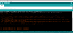
Соскочил с Винды на Ubuntu (чему несказанно рад) и установив Arduino IDE получил проблему с прошивкой модулей на основе esp8266, а именно
Wemos d1 r2 и Nodemcu v3. Ошибка: esptool.FatalError: Failed to connect to ESP8266: Timed out waiting for packet header
Причем обе платы выдают в Serial вполне читаемые символы от скетчей прошитых еще под Виндой.
Попытка прошить через консоль с esptool привела к той же ошибке.
AVR и ESP32 прошиваются без проблем. Модуль esp8266 на борту Mega 2560 wifi тоже прошился без ошибок.
Help кто чем может.
зы: гнезда и кабели USB менял, все разрешения в Ubuntu оформил, драйвер ch340 в Ubuntu стоит по умолчанию.
-
#2
У меня Nodemcu3 cp2102 на xubuntu работает.
Проверьте python и добавления в нужные группы.
Установщик adrduinoide запускали?
-
#3
У меня Nodemcu3 cp2102 на xubuntu работает.
Проверьте python и добавления в нужные группы.
Установщик adrduinoide запускали?
ну отличить cp2102 от ch340 вроде не трудно. у меня последний
можно чуть больше для туповатых на что именно проверить python ?
уcтановщик? сам Arduino IDE установлен, если я правильно помню, через snap
-
#4
Попробуйте установить вручную.
-
#5
что именно проверить python ?
Установлен ли, какой версии.
-
#6
Попробуйте установить вручную.
попробовать то можно…..только вот esptool в консоли на бинарник точно также ругается
-
#7
Установлен ли, какой версии.
куда ж без него Python 3.8.10
-
#8
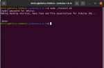
вот что пишет esptool.py на запросы chip_id и flash_id:
esptool.py v3.1
Found 1 serial ports
Serial port /dev/ttyUSB0
Connecting…….._____….._____….._____….._____….._____….._____….._____
/dev/ttyUSB0 failed to connect: Failed to connect to Espressif device: Timed out waiting for packet header
A fatal error occurred: Could not connect to an Espressif device on any of the 1 available serial ports.
-
#9
на AT комманды реагирует ERROR
-
#11
Ничего не вышло((. Все по инструкции сделал.
Даже Ubuntu переустановил))
На Меге 2560 стоит тот же чип ch340g. Нкаких проблем.
-
#12
У меня Nodemcu3 cp2102 на xubuntu работает.
Проверьте python и добавления в нужные группы.
Установщик adrduinoide запускали?
если завалялась где-нибудь nodemcu на ch340 попробуй, плиз, прошить как время будет
-
#13
В ide сом порт виден?
По какому пути установили? Лог установки.
Покажите вывод в сериал на скорости 74800, после нажатия ресета на есп.
И не надо много писать, покажите скриншотами.
-
#14
В ide сом порт виден?
По какому пути установили? Лог установки.
Покажите вывод в сериал на скорости 74800, после нажатия ресета на есп.
И не надо много писать, покажите скриншотами.
В сериал монитор ничего не выводит на такой скорости. Логи после ресета во вложении.
-

75.3 KB
Просмотры: 9
-
#15
В ide сом порт виден?
По какому пути установили? Лог установки.
Покажите вывод в сериал на скорости 74800, после нажатия ресета на есп.
И не надо много писать, покажите скриншотами.
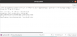
порт виден. в сериал монитор выводит если скорость установить соответсвующую.
Логи установки IDE не богатые.
-
30.5 KB
Просмотры: 7
-
#16
В сериал монитор ничего не выводит на такой скорости.Логи после ресета во вложении.
Так это не сериал монитор. Ищите его запуск в меню.
Подайте на есп внешнее питание.
-
#17
Так это не сериал монитор. Ищите его запуск в меню.
Подайте на есп внешнее питание.
Просто в сериал мониторе на скорости 74880 нет ничего интересного, на мой взгляд.
На установленной в ранее прошитом скетче 115200 хоть символы человеческие выводит.
-
16.5 KB
Просмотры: 9 -
30.4 KB
Просмотры: 9
-
#18
Просто в сериал мониторе на скорости 74880 нет ничего интересного, на мой взгляд.
А должна быть видна загрузочная информация.
Что с питанием.
-
#19
А должна быть видна загрузочная информация.
Что с питанием.
всегда хватало питания от USB.
бросил на vin и gnd дополнительно 5 вольт. ничего не поменялось. прибавил до 7, тот же результат
-
#20
Переведите есп в режим программирования вручную и попробуйте прошить.
After releasing some projects with the ESP32-CAM, some readers reported issues when trying to use the ESP32-CAM. This guide is a compilation with the most common errors when using the ESP32-CAM and how to fix them.

We’ve released the following projects with the ESP32-CAM:
- Video Streaming, Face Detection and Face Recognition
- ESP32 IP CAM – Video Streaming (Home Assistant and Node-RED)
- Take Photo and Save to MicroSD Card
- PIR Motion Detector with Photo Capture
- Take Photo, Save to SPIFFS and Display in Web Server
Note: some of our readers reported errors when trying to follow the ESP32-CAM project with Home Assistant. We’ve modified some lines on the code, so most of the problems related with that project should be fixed.
Please note that we couldn’t reproduce some of the errors on our end. However, we’ve gathered all the information given by our readers to get answers to the most common issues.
If you have a different problem or a different solution to these issues, you can share your tips by writing a comment below.
Most common errors:
- Failed to connect to ESP32: Timed out waiting for packet header
- Camera init failed with error 0x20001 or similar
- Brownout detector or Guru meditation error
- Sketch too big error – Wrong partition scheme selected
- Board at COMX is not available – COM Port Not Selected
- Psram error: GPIO isr service is not installed
- Weak Wi-Fi Signal
- No IP Address in Arduino IDE Serial Monitor
- Can’t open web server
- The image lags/shows lots of latency
- esp_camera_fb_get(): Failed to get the frame on time!
1. Failed to connect to ESP32: Timed out waiting for packet header

This error means that the ESP32-CAM is not in flashing mode or it is not connected properly to the FTDI programmer.
Double-check the steps to upload code
Double-check that you’ve followed the exact steps to put your ESP32-CAM in flashing mode. Failing to complete one of the steps may result in that error. Here’s the steps you need to follow:
Connect the ESP32-CAM board to your computer using an FTDI programmer. Follow the next schematic diagram:

Important: GPIO 0 needs to be connected to GND so that you’re able to upload code.
Many FTDI programmers have a jumper that allows you to select 3.3V or 5V. Make sure the jumper is in the right place to select 5V.
Important: GPIO 0 needs to be connected to GND so that you’re able to upload code.
| ESP32-CAM | FTDI Programmer |
| GND | GND |
| 5V | VCC (5V) |
| U0R | TX |
| U0T | RX |
| GPIO 0 | GND |
To upload the code, follow the next steps:
1) Go to Tools > Board and select AI-Thinker ESP32-CAM.
2) Go to Tools > Port and select the COM port the ESP32 is connected to.
3) Then, click the upload button to upload the code.
4) When you start to see these dots on the debugging window as shown below, press the ESP32-CAM on-board RST button.

After a few seconds, the code should be successfully uploaded to your board.
GPIO 0 must be connected to GND
Important: if you can’t upload the code, double-check that GPIO 0 is connected to GND and that you selected the right settings in the Tools menu. You should also press the on-board Reset button to restart your ESP32 in flashing mode. Also, check that you have the FTDI programmer jumper cap set to 5V.
Check the FTDI programmer you are using
One of our readers reported the following: “found out that you can program the board with a USB-to-TTL module model CP2102 and that the CH340 model does NOT work“. This is the FTDI programmer we’re using.
Power the ESP32-CAM with 5V
Some of our readers reported that they could only upload code when the ESP32 was powered with 5V. So, power the ESP32-CAM with 5V.
FTDI Programmer 5V
Measure the output voltage of your FTDI programmer (VCC and GND) using a Multimeter to ensure it’s providing 5V to your ESP32-CAM.

2. Camera init failed with error 0x20001 or similar

If you get this exact error, it means that your camera OVX is not connected properly to your ESP32 board or you have the wrong pin assignment in the code.
Sometimes, unplugging and plugging the FTDI programmer multiple times or restart the board multiple times, might solve the issue.
Camera not connected properly
The camera has a tiny connector and you must ensure it’s connected in the the right away and with a secure fit, otherwise it will fail to establish a connection.
Wrong pin assignment in the code
When you get this error, it might also mean that you didn’t select the right board in the define section or the pin definition is wrong for your board.
Make sure you select the right camera module in your projects. You just need to uncomment the right camera module and comment all the others:
//#define CAMERA_MODEL_WROVER_KIT
//#define CAMERA_MODEL_M5STACK_PSRAM
#define CAMERA_MODEL_AI_THINKER
In this example, we’re using the CAMERA_MODEL_AI_THINKER, so it’s the one that is enabled. Otherwise, it will fail the pin assignment and the camera will fail to init.
There are many esp32-cam boards being released (“fake boards”) that the wiring between the ESP32 and the OV camera might be different, so selecting the camera module, might not be enough. You might need to check each gpio declaration with your board pinout.
For example, M5Stack board without PSRAM has a different pin assignment than the M5STACK with PSRAM (defined on the code by default). So, you need to change the pin definition in the code accordingly to the board pinout.
Not enough power through USB source
If you’re powering your ESP32 through a USB port on your computer, it might not be supplying enough power.
Faulty FTDI programmer
Some readers also reported this problem was solved by replacing their actual FTDI programmer with this one.
The camera/connector is broken
If you get this error, it might also mean that your camera or the camera ribbon is broken. If that is the case, you may get a new OV2640 camera probe.
3. Brownout detector or Guru meditation error
When you open your Arduino IDE Serial monitor and the error message “Brownout detector was triggered” is constantly being printed over and over again. It means that there’s some sort of hardware problem.
It’s often related to one of the following issues:
- Poor quality USB cable;
- USB cable is too long;
- Board with some defect (bad solder joints);
- Bad computer USB port;
- Or not enough power provided by the computer USB port.
Solution:
- try a different shorter USB cable (with data wires)
- use a different computer USB port or use a USB hub with an external power supply
- some readers reported that when powering the ESP32-CAM with 5V, the issue was fixed.
Also, follow the suggestions described in issue 2.
4. Sketch too big error – Wrong partition scheme selected

When you get the following error:
Sketch too big; see http://www.arduino.cc/en/Guide/Troubleshooting#size for tips on reducing it.
Error compiling for board ESP32 Dev Module.
It means that you haven’t selected the right partition scheme. Make sure you select the right partition scheme. In your Arduino IDE, go to Tools > Partition Scheme, select “Huge APP (3MB No OTA)“.
5. Board at COMX is not available – COM Port Not Selected

If you get the following error or similar:
serial.serialutil.SerialException: could not open port 'COM8': WindowsError(2, 'The system cannot find the file specified.')
Failed to execute script esptool
the selected serial port Failed to execute script esptool
 does not exist or your board is not connected
Board at COM8 is not available
It means that you haven’t selected the COM port in the Tools menu. In your Arduino IDE, go to Tools > Port and select the COM port the ESP32 is connected to.
It might also mean that the ESP32-CAM is not establishing a serial connection with your computer or it is not properly connected to the USB connector.
6. Psram error: GPIO isr service is not installed

You are using a board without PSRAM and you get the following error or similar:
E (161) gpio: gpio_isr_handler_remove(380): GPIO isr service is not installed, call gpio_install_isr_service() first
Camera init failed with error 0x101
when the board was initialized with the following settings:
config.frame_size = FRAMESIZE_UXGA;
config.jpeg_quality = 10;
config.fb_count = 2;
Adding the following fixes the issues (it lowers the image resolution so it won’t need so much space to store images. However, as a result, you cannot get some high resolution formats due to the limited memory):
if(psramFound()){
  config.frame_size = FRAMESIZE_UXGA;
  config.jpeg_quality = 10;
  config.fb_count = 2;
} else {
  config.frame_size = FRAMESIZE_SVGA;
  config.jpeg_quality = 12;
  config.fb_count = 1;
}
Note: face recognition and detection doesn’t work with boards without PSRAM. However, you can still use all the other functionalities of the board. For example, although you can’t use the face recognition and detection features of this project (ESP32-CAM Video Streaming and Face Recognition with Arduino IDE), you can still play with the example and explore the board features as long as you have the right pin assignment in the code.
7. Weak Wi-Fi Signal
Some readers reported that after powering the ESP32-CAM with 5V, they’ve gotten a more stable Wi-Fi signal. You can read this dedicated guide to learn how to connect an external antenna to the ESP32-CAM and extend Wi-Fi coverage.
The ESP32-CAM has the option to use either the built-in antenna or an external antenna. If your ESP32-CAM AI-Thinker has no Wi-Fi connection or poor connection, it might have the external antenna enabled. If you connect an external antenna to the connector, it should work fine.
Check if the jumper 0K resistor by the antenna connector is in the proper position for the desired antenna. There are 3 little white squares laid out like a “<” with the middle position being common.

The following photo shows a closer look at that area. You can clearly see a small 0K resistor connecting to the built-in antenna.

With board turned so the the PCB antenna is up:
- To use the PCB antenna, the resistor must be on the top position, like this: /
- For the antenna connector, the resistor must be on the bottom position, like this:
So, to enable the on-board antenna:
- Unsolder the resistor that goes to the antenna, it’s in this position
- And solder together the two connections to enable the on-board antenna.
8. No IP Address in Arduino IDE Serial Monitor
f you just see dots printed in the serial monitor (……), it means that your ESP32-CAM is not establishing a Wi-Fi connection with your router.
Double-check your network credentials
You need to make sure that you’ve typed your exact network credentials (SSID and password) in the following variables:
const char* ssid = "REPLACE_WITH_YOUR_SSID";
const char* password = "REPLACE_WITH_YOUR_PASSWORD";
Select the right baud rate in the Arduino IDE Serial Monitor
If you don’t select the right baud rate in the Arduino IDE Serial Monitor, you won’t get your board IP address or you’ll just get garbage on the screen.
Make sure you select the right baud rate. In our examples with the ESP32-CAM, we use 115200 baud rate.
Reset the board multiple times
You might also need to press the ESP32-CAM on-board RESET button multiple times to restart your ESP and print the IP address during boot.
RX and TX swapped
Double-check the connections between your ESP32 board and the FTDI programmer. RX goes to TX and TX goes to RX. If these connections are swapped, the ESP32-CAM is not able to establish a serial communication with your computer.
Wi-Fi Range
If the router is far away from your ESP32 board, it might not be able to catch the Wi-Fi signal. Ensure that your ESP32-CAM is fairly close to your router.
9. Can’t open web server
If the ESP32-CAM is printing the IP address in your Arduino IDE Serial Monitor, but when you try to open the web server in your web browser you see a blank screen, it usually means that you are trying to access the ESP32-CAM web server with multiple web browser tabs.
At the moment, these ESP32-CAM sketches only work with one client connected at a time.
10. The image lags/shows lots of latency
Having some latency is normal for such a small and cheap camera. Some readers have suggested the following to reduce latency:
- Power the ESP32-CAM with a standalone 5V power supply
- Reduce the frame size with the following in your code:
config.frame_size = FRAMESIZE_SVGA or config.frame_size = FRAMESIZE_VGA - Use an external antenna.
11. esp_camera_fb_get(): Failed to get the frame on time!
We’ve personally never faced this issue. However, many readers are getting this error with their ESP32-CAM boards.
One of our readers (Fibula) suggested the following to solve this issue:
“Im using the ESP32-CAM Module 2MP OV2640 Camera sensor Module Type-C USB module from Aliexpress. Although not mentioned, It doesn’t have the extra PSRAM the other M5 models do, and the camera has one changed IO pin.
See here: https://github.com/m5stack/m5stack-cam-psram/blob/master/README.md and scroll down to Interface Comparison.
The CameraWebServer Arduino example we’re probably all using doesn’t have this ESP32-CAM model defined.
You need to add it yourself in the main tab add:
#define CAMERA_MODEL_M5STACK_NO_PSRAMAnd in the camera_pins.h tab add the following:
#elif defined(CAMERA_MODEL_M5STACK_NO_PSRAM)
#define PWDN_GPIO_NUM -1
#define RESET_GPIO_NUM 15
#define XCLK_GPIO_NUM 27
#define SIOD_GPIO_NUM 25
#define SIOC_GPIO_NUM 23
#define Y9_GPIO_NUM 19
#define Y8_GPIO_NUM 36
#define Y7_GPIO_NUM 18
#define Y6_GPIO_NUM 39
#define Y5_GPIO_NUM 5
#define Y4_GPIO_NUM 34
#define Y3_GPIO_NUM 35
#define Y2_GPIO_NUM 17
#define VSYNC_GPIO_NUM 22
#define HREF_GPIO_NUM 26
#define PCLK_GPIO_NUM 21
And you’re good to go.
Also note that the max resolution of the bare ESP32-CAM Module is XGA 1024×768, I assume also because of the lack of PSRAM. “
We hope this suggestion solves your issue. Let us know in the comments section.
Using larger microSD card sizes
According to he datasheet, the ESP32-CAM should only supports 4GB microSD cards.
However, we’ve tested with 16GB microSD card and it works well.
You might not be able to store more than 4GB, even though you have 16GB. We haven’t tested storing more than 4GB, so we’re not sure about this.
Are these projects compatible with M5Stack board?
Yes, the M5Stack ESP32 board is compatible with out projects. However, you must check your camera pinout to ensure you have the right assignment in the code.
You can check the M5Stack camera connections here.
How to set a fixed the IP Address
To set a static/fixed IP address, you can follow the next tutorial:
- ESP32 Static/Fixed IP Address
Setting ESP32-CAM as Access Point (AP)
You can set your ESP32-CAM as an Access Point (AP). This means you are able to connect to your ESP32-CAM directly without having to connect to your router. You can use the following code to set your video streaming web server as an Access Point:
/*********
  Rui Santos
  Complete project details at https://RandomNerdTutorials.com/esp32-cam-video-streaming-web-server-camera-home-assistant/

  IMPORTANT!!!
   - Select Board "AI Thinker ESP32-CAM"
   - GPIO 0 must be connected to GND to upload a sketch
   - After connecting GPIO 0 to GND, press the ESP32-CAM on-board RESET button to put your board in flashing mode

  Permission is hereby granted, free of charge, to any person obtaining a copy
  of this software and associated documentation files.

  The above copyright notice and this permission notice shall be included in all
  copies or substantial portions of the Software.
*********/

#include "esp_camera.h"
#include <WiFi.h>
#include "esp_timer.h"
#include "img_converters.h"
#include "Arduino.h"
#include "fb_gfx.h"
#include "soc/soc.h" //disable brownout problems
#include "soc/rtc_cntl_reg.h"  //disable brownout problems
#include "esp_http_server.h"

// Replace with your network credentials
const char* ssid     = "ESP32-Access-Point";
const char* password = "123456789";

#define PART_BOUNDARY "123456789000000000000987654321"

// This project was tested with the AI Thinker Model, M5STACK PSRAM Model and M5STACK WITHOUT PSRAM
#define CAMERA_MODEL_AI_THINKER
//#define CAMERA_MODEL_M5STACK_PSRAM
//#define CAMERA_MODEL_M5STACK_WITHOUT_PSRAM

// Not tested with this model
//#define CAMERA_MODEL_WROVER_KIT

#if defined(CAMERA_MODEL_WROVER_KIT)
  #define PWDN_GPIO_NUM    -1
  #define RESET_GPIO_NUM   -1
  #define XCLK_GPIO_NUM    21
  #define SIOD_GPIO_NUM    26
  #define SIOC_GPIO_NUM    27

  #define Y9_GPIO_NUM      35
  #define Y8_GPIO_NUM      34
  #define Y7_GPIO_NUM      39
  #define Y6_GPIO_NUM      36
  #define Y5_GPIO_NUM      19
  #define Y4_GPIO_NUM      18
  #define Y3_GPIO_NUM       5
  #define Y2_GPIO_NUM       4
  #define VSYNC_GPIO_NUM   25
  #define HREF_GPIO_NUM    23
  #define PCLK_GPIO_NUM    22

#elif defined(CAMERA_MODEL_M5STACK_PSRAM)
  #define PWDN_GPIO_NUM     -1
  #define RESET_GPIO_NUM    15
  #define XCLK_GPIO_NUM     27
  #define SIOD_GPIO_NUM     25
  #define SIOC_GPIO_NUM     23

  #define Y9_GPIO_NUM       19
  #define Y8_GPIO_NUM       36
  #define Y7_GPIO_NUM       18
  #define Y6_GPIO_NUM       39
  #define Y5_GPIO_NUM        5
  #define Y4_GPIO_NUM       34
  #define Y3_GPIO_NUM       35
  #define Y2_GPIO_NUM       32
  #define VSYNC_GPIO_NUM    22
  #define HREF_GPIO_NUM     26
  #define PCLK_GPIO_NUM     21

#elif defined(CAMERA_MODEL_M5STACK_WITHOUT_PSRAM)
  #define PWDN_GPIO_NUM     -1
  #define RESET_GPIO_NUM    15
  #define XCLK_GPIO_NUM     27
  #define SIOD_GPIO_NUM     25
  #define SIOC_GPIO_NUM     23

  #define Y9_GPIO_NUM       19
  #define Y8_GPIO_NUM       36
  #define Y7_GPIO_NUM       18
  #define Y6_GPIO_NUM       39
  #define Y5_GPIO_NUM        5
  #define Y4_GPIO_NUM       34
  #define Y3_GPIO_NUM       35
  #define Y2_GPIO_NUM       17
  #define VSYNC_GPIO_NUM    22
  #define HREF_GPIO_NUM     26
  #define PCLK_GPIO_NUM     21

#elif defined(CAMERA_MODEL_AI_THINKER)
  #define PWDN_GPIO_NUM     32
  #define RESET_GPIO_NUM    -1
  #define XCLK_GPIO_NUM      0
  #define SIOD_GPIO_NUM     26
  #define SIOC_GPIO_NUM     27

  #define Y9_GPIO_NUM       35
  #define Y8_GPIO_NUM       34
  #define Y7_GPIO_NUM       39
  #define Y6_GPIO_NUM       36
  #define Y5_GPIO_NUM       21
  #define Y4_GPIO_NUM       19
  #define Y3_GPIO_NUM       18
  #define Y2_GPIO_NUM        5
  #define VSYNC_GPIO_NUM    25
  #define HREF_GPIO_NUM     23
  #define PCLK_GPIO_NUM     22
#else
  #error "Camera model not selected"
#endif

static const char* _STREAM_CONTENT_TYPE = "multipart/x-mixed-replace;boundary=" PART_BOUNDARY;
static const char* _STREAM_BOUNDARY = "rn--" PART_BOUNDARY "rn";
static const char* _STREAM_PART = "Content-Type: image/jpegrnContent-Length: %urnrn";

httpd_handle_t stream_httpd = NULL;

static esp_err_t stream_handler(httpd_req_t *req){
  camera_fb_t * fb = NULL;
  esp_err_t res = ESP_OK;
  size_t _jpg_buf_len = 0;
  uint8_t * _jpg_buf = NULL;
  char * part_buf[64];

  res = httpd_resp_set_type(req, _STREAM_CONTENT_TYPE);
  if(res != ESP_OK){
    return res;
  }

  while(true){
    fb = esp_camera_fb_get();
    if (!fb) {
      Serial.println("Camera capture failed");
      res = ESP_FAIL;
    } else {
      if(fb->width > 400){
        if(fb->format != PIXFORMAT_JPEG){
          bool jpeg_converted = frame2jpg(fb, 80, &_jpg_buf, &_jpg_buf_len);
          esp_camera_fb_return(fb);
          fb = NULL;
          if(!jpeg_converted){
            Serial.println("JPEG compression failed");
            res = ESP_FAIL;
          }
        } else {
          _jpg_buf_len = fb->len;
          _jpg_buf = fb->buf;
        }
      }
    }
    if(res == ESP_OK){
      size_t hlen = snprintf((char *)part_buf, 64, _STREAM_PART, _jpg_buf_len);
      res = httpd_resp_send_chunk(req, (const char *)part_buf, hlen);
    }
    if(res == ESP_OK){
      res = httpd_resp_send_chunk(req, (const char *)_jpg_buf, _jpg_buf_len);
    }
    if(res == ESP_OK){
      res = httpd_resp_send_chunk(req, _STREAM_BOUNDARY, strlen(_STREAM_BOUNDARY));
    }
    if(fb){
      esp_camera_fb_return(fb);
      fb = NULL;
      _jpg_buf = NULL;
    } else if(_jpg_buf){
      free(_jpg_buf);
      _jpg_buf = NULL;
    }
    if(res != ESP_OK){
      break;
    }
    //Serial.printf("MJPG: %uBn",(uint32_t)(_jpg_buf_len));
  }
  return res;
}

void startCameraServer(){
  httpd_config_t config = HTTPD_DEFAULT_CONFIG();
  config.server_port = 80;

  httpd_uri_t index_uri = {
    .uri       = "/",
    .method    = HTTP_GET,
    .handler   = stream_handler,
    .user_ctx  = NULL
  };

  //Serial.printf("Starting web server on port: '%d'n", config.server_port);
  if (httpd_start(&stream_httpd, &config) == ESP_OK) {
    httpd_register_uri_handler(stream_httpd, &index_uri);
  }
}

void setup() {
  WRITE_PERI_REG(RTC_CNTL_BROWN_OUT_REG, 0); //disable brownout detector

  Serial.begin(115200);
  Serial.setDebugOutput(false);

  camera_config_t config;
  config.ledc_channel = LEDC_CHANNEL_0;
  config.ledc_timer = LEDC_TIMER_0;
  config.pin_d0 = Y2_GPIO_NUM;
  config.pin_d1 = Y3_GPIO_NUM;
  config.pin_d2 = Y4_GPIO_NUM;
  config.pin_d3 = Y5_GPIO_NUM;
  config.pin_d4 = Y6_GPIO_NUM;
  config.pin_d5 = Y7_GPIO_NUM;
  config.pin_d6 = Y8_GPIO_NUM;
  config.pin_d7 = Y9_GPIO_NUM;
  config.pin_xclk = XCLK_GPIO_NUM;
  config.pin_pclk = PCLK_GPIO_NUM;
  config.pin_vsync = VSYNC_GPIO_NUM;
  config.pin_href = HREF_GPIO_NUM;
  config.pin_sscb_sda = SIOD_GPIO_NUM;
  config.pin_sscb_scl = SIOC_GPIO_NUM;
  config.pin_pwdn = PWDN_GPIO_NUM;
  config.pin_reset = RESET_GPIO_NUM;
  config.xclk_freq_hz = 20000000;
  config.pixel_format = PIXFORMAT_JPEG;

  if(psramFound()){
    config.frame_size = FRAMESIZE_UXGA;
    config.jpeg_quality = 10;
    config.fb_count = 2;
  } else {
    config.frame_size = FRAMESIZE_SVGA;
    config.jpeg_quality = 12;
    config.fb_count = 1;
  }

  // Camera init
  esp_err_t err = esp_camera_init(&config);
  if (err != ESP_OK) {
    Serial.printf("Camera init failed with error 0x%x", err);
    return;
  }
  // Connect to Wi-Fi network with SSID and password
  Serial.print("Setting AP (Access Point)…");
  // Remove the password parameter, if you want the AP (Access Point) to be open
  WiFi.softAP(ssid, password);

  IPAddress IP = WiFi.softAPIP();
  Serial.print("Camera Stream Ready! Connect to the ESP32 AP and go to: http://");
  Serial.println(IP);

  // Start streaming web server
  startCameraServer();
}

void loop() {
  delay(1);
}
View raw code
To better understand how it works, you can read the next tutorial:
- ESP32 Access Point (AP) for Web Server
Wrapping Up
We hope you’ve found this troubleshooting guide useful and you were able to make your ESP32-CAM work with our projects.
If you have any other issues or suggestions on how to fix them, please post a comment below.
If you like this project, you may also like other projects with the ESP32-CAM:
- ESP32-CAM AI-Thinker Pinout Guide: GPIOs Usage Explained
- Video Streaming, Face Detection and Face Recognition
- Build ESP32-CAM Projects (eBook)
- Read all our ESP32-CAM Projects, Tutorials and Guides
Thank you for reading.
P.S. It is very difficult to understand what’s wrong with your project when we can’t reproduce the error on our end. However, if you post the error, there might be other readers with the same issue/solution, so we encourage you to interact in the comment’s section.