Trouble shooting 34
OUTDOOR UNIT Error Method:
Detective Actuators:
Discharge temperature thermistor
Forecast of Cause :
1. 3-way valve not opened
2. EEV defective, strainer clogged
3. Outdoor unit operation
4. Discharge temperature thermistor
5. Insufficient refrigerant
<Cooling operation>
Check Point 1 : Check if 3-way valve(gas side) is open.
If the 3-way valve(gas side) was closed, open the
3-way valve(gas side) and check operation.
OK
Check Point 2 : Check the EEV, strainer
EEV (EEV2, indoor unit EEV) open?
Strainer clogging check (before and after EEV, ACM
oil return)
Refer to «Service Parts Information 3, 4 «
OK
Check Point 3 : Check the outdoor unit fan,heat exchanger
Check for foreign object at heat exchanger
Check if fan can be rotated by hand.
Motor check(PARTS INFORMATION 7)
OK
:
Check Point 4 : Check the discharge thermistor
Discharger thermistor characteristics check
(Check by disconnecting thermistor from PCB.)
* For the characteristics of the thermistor, refer to the «Service Parts Information 5».
OK
Check Point 5 : Check the refrigerant amount
Leak check
Indicate or Display:
Outdoor Unit : E. A1. 1
Indoor Unit
: Operation LED 10 times Flash, Timer LED 1 Times Flash,
Economy LED Continuous Flash.
Error Code
: A1
Detective details:
«Protection stop by «discharge temperature
operation»» generated 2 times within 24 hours.
failure
, foreign matter on heat exchanger
failure
<Heating operation>
Check Point 1 : Check if 3-way valve(liquid side) is open.
If the 3-way valve(liquid side) was closed, open the
3-way valve(liquid side) and check operation.
Check Point 2 : Check the EEV, strainer
EEV (EEV1, EEV2) open?
Strainer clogging check (before and after EEV, ACM
oil return)
Refer to «Service Parts Information 3, 4»
OK
02-50
°C
115
during compressor
OK
Когда на дисплее пульта показывает EE:EE, нажмите одновременно
две кнопки “Energy Save” + “Zone Control” и удерживайте дольше 3х сек..
Код ошибки будет показан на дисплее.
E0:00 Coms error — indoor to remote
E1:00 Coms error — indoor to outdoor
E2:00 Return air thermistor open circuit
E3:00 Return air thermistor short circuit
E4:00 Indoor coil thermistor open
E5:00 Indoor coil thermistor shorted
E6:00 Outdoor coil thermistor open
E7:00 Outdoor coil thermistor shorted
EA:00 Outdoor ambient thermistor open
Eb:00 Outdoor ambient thermistor shorted
Ec:00 Discharge pipe themistor open
Ed:00 Discharge pipe thermistor shorted
EE:00 High Pressure problem
EF:00 Discharge pipe temp. Problem — too high = short of gas
Press “Energy Save” & “Zone Control” buttons simultaneously for longer
than 3 secs to return to normal operating mode
(1) Stop the air conditioner operation.
(2) Press the master control button and the fan control button simultaneously for 2 seconds or more to start the test run
(3) Press the start/stop button to stop the test run

[SELF-DIAGNOSIS]
When the error indication E:EE is displayed, follow the following items
to perform the self-diagnosis. E:EE indicates an error has occurred.
1. REMOTE CONTROLLER DISPLAY
1) Stop the air conditioner operation.
2) Press the set temperature buttons simultaneously for 5 seconds or more to start the self-diagnosis.
Refer to the following tables for the description of each error code
(3) Press the set temperature buttons simultaneously for 5 seconds or more to stop the self-diagnosis.

Error code = 00
Error contents = Communication error (indoor unit to remote controller)
Error code = 01
Error contents = Communication error (indoor unit to outdoor unit)
Error code = 02
Error contents = Room temperature sensor open
Error code = 03
Error contents = Room temperature sensor short-circuited
Error code = 04
Error contents = Indoor heat exchanger temperature sensor open
Error code = 05
Error contents = Indoor heat exchanger temperature sensor shortcircuited
Error code = 06
Error contents = Outdoor heat exchanger temperature sensor open
Error code = 07
Error contents = Outdoor heat exchanger temperature sensor shortcircuit
Error code = 08
Error contents = Power source connection error
Error code = 09
Error contents = Float switch operated
Error code = 0A
Error contents = Outdoor temperature sensor open
Error code = 0b
Error contents = Outdoor temperature sensor short-circuited
Error code = 0c
Error contents = Discharge pipe temperature sensor open
Error code = 0d
Error contents = Discharge pipe temperature sensor short-circuited
Error code = 0E
Error contents = Outdoor high pressure abnormal
Error code = 0F
Error contents = Discharge pipe temperature abnormal
Error code = 11
Error contents = Model abnormal
Error code = 12
Error contents = Indoor fan abnormal
Error code = 13
Error contents = Outdoor signal abnormal
Error code = 14
Error contents = Outdoor EEPROM abnormal
2. OUTDOOR UNIT LEDS
When the outdoor temperature drops, the outdoor units fans may switch
to low speed.
ERROR : HEAT & COOL MODEL (REVERSE CYCLE) ONLY
The LED lamps operate as follows according to the error contents.

These pages cover the current Inverter product range.
They also cover the ARY60U, ARY54U Single and AOY19/24F/U Multi Systems.
Models with Wireless Controllers
Trouble Shooting from the Indoor Unit
Wall Mounted Single Systems ASY, ASYA & ASYB
Includes AWYZ Nokria Models
Red Light Operation = Off Green Light Timer = 2 Flashes
Reverse Comms Fail at Startup
Red Light Operation = Off
Green Light Timer = 3 Flashes
Reverse Comms Fail In Use
Red Light Operation = Off
Green Light Timer = 4 Flashes
Forward Comms Fail at Startup
Red Light Operation = Off
Green Light Timer = 5 Flashes
Forward Comms Fail In Use
Red Light Operation = Off
Green Light Timer = 8 Flashes
Wired Remote Control Failure
Red Light Operation = 2 Flashes
Green Light Timer = 2 Flashes
Indoor Air Sensor Fail
Red Light Operation = 2 Flashes
Green Light Timer = 3 Flashes
Indoor Pipe Sensor Fail
Red Light Operation = 3 Flashes
Green Light Timer = 2 Flashes OD
Disch Sensor Fail
Red Light Operation = 3 Flashes
Green Light Timer = 3 Flashes OD
Pipe Sensor Fail
Red Light Operation = 3 Flashes
Green Light Timer = 4 Flashes OD
Air Sensor Fail
Red Light Operation = 3 Flashes
Green Light Timer = 8 Flashes
Compressor Temp Sensor Fail
Red Light Operation = 4 Flashes Green Light Timer = 2 Flashes
Forced Auto Switch Welded
Red Light Operation = 4 Flashes
Green Light Timer = 3 Flashes
Main Relay Welded
Red Light Operation = 4 Flashes
Green Light Timer = 4 Flashes
Power Failure
Red Light Operation = 4 Flashes
Green Light Timer = 7 Flashes
VDD Permament Stop Protection
Red Light Operation = 4 Flashes
Green Light Timer = 8 Flashes
Reverse VDD Permament Stop
Red Light Operation = 5 Flashes
Green Light Timer = 2 Flashes
Current Trip
Red Light Operation = 5 Flashes
Green Light Timer = 3 Flashes
CT Abnormal
Red Light Operation = 5 Flashes
Green Light Timer = 5 Flashes
Compressor Failure
Red Light Operation = 5 Flashes
Green Light Timer = 6 Flashes
Outdoor Fan Failure
Red Light Operation = 6 Flashes
Green Light Timer = 2 Flashes
ID Fan Motor Locked
Red Light Operation = 6 Flashes
Green Light Timer = 3 Flashes
ID Fan Motor Rotation Error
Red Light Operation = 7 Flashes
Green Light Timer = 2 Flashes
High Discharge Temperature
Red Light Operation = 7 Flashes
Green Light Timer = 3 Flashes
High Pressure
Red Light Operation = 7 Flashes
Green Light Timer = 5 Flashes
Pressure Switch Fail
Red Light Operation = 8 Flashes
Green Light Timer = 2 Flashes
Active Filter AFM Fail 1st Time
Red Light Operation = 8 Flashes
Green Light Timer = 3 Flashes
Active Filter AFM Fail 2nd Time
Red Light Operation = 8 Flashes
Green Light Timer = 4 Flashes
PFC Circuit Error
Red Light Operation = Blinking
Green Light Timer = Blinking
PCB Failure
All Other Wireless Indoor Units AUY, ABY & AWY Models
Including Multi Systems (Not J Series or VRF)
Red Light operation = On
Green Light Timer =
Yellow Light Swing =
Normal
Red Light operation = On
Green Light Timer = Slow Blink
Yellow Light Swing = Slow Blink
Test
Red Light operation = Blinks
Green Light Timer = Blinks
Yellow Light Swing = Off
ID PCB Fail
Red Light operation = Blinks
Green Light Timer = Blinks
Yellow Light Swing = Blinks
OD PCB Fail
Red Light operation = Blinks
Green Light Timer = 2 Pulses
Yellow Light Swing = Off
OD Power Connection Failure
Red Light operation = Blinks
Green Light Timer =3 Pulses
Yellow Light Swing = Off
OD Unit Pipe Sensor Fail
Red Light operation = Blinks
Green Light Timer =4 Pulses
Yellow Light Swing = Off OD
Unit Air sensor Fail
Red Light operation = Blinks
Green Light Timer =4 Pulses
Yellow Light Swing = Blinks
OD Unit Air sensor Short
Red Light operation = Blinks
Green Light Timer = 5 Pulses
Yellow Light Swing = Off
OD Unit Disch Sensor Fail
Red Light operation = Blinks
Green Light Timer = 5 Pulses
Yellow Light Swing = Blinks
OD Unit Disch Sensor Short
Red Light operation = Blinks
Green Light Timer = 6 Pulses
Yellow Light Swing = Off
High Pressure
Red Light operation = Blinks
Green Light Timer = 7 Pulses
Yellow Light Swing = Off
High Discharge or Compressor Temp
Red Light operation = Blinks
Green Light Timer = 9 Pulses
Yellow Light Swing = Off
OD Unit Compressor Temp Sensor
Red Light operation = Blinks
Green Light Timer = 10 Pulses
Yellow Light Swing = Off
IPM Error
Red Light operation = Blinks
Green Light Timer = 11 Pulses
Yellow Light Swing = Off
CT Error
Red Light operation = Blinks
Green Light Timer = 12 Pulses
Yellow Light Swing = Off
AFM Filter Error
Red Light operation = Blinks
Green Light Timer = 13 Pulses
Yellow Light Swing = Off
Compressor Error
Red Light operation = Blinks
Green Light Timer = 14 Pulses
Yellow Light Swing = Off
OD Fan Motor Fail
Red Light operation = 2 Pulses
Green Light Timer = Blinks
Yellow Light Swing = Off
Air Sensor Open
Red Light operation = 2 Pulses
Green Light Timer = Blinks
Yellow Light Swing = Blinks
Air Sensor Closed
Red Light operation = 3 Pulses
Green Light Timer = Blinks
Yellow Light Swing = Off
Pipe Sensor Open
Red Light operation = 3 Pulses
Green Light Timer = Blinks
Yellow Light Swing = Blinks
Pipe Sensor Closed
Red Light operation = 4 Pulses
Green Light Timer = Blinks
Yellow Light Swing = Off
Drain Problem
Red Light operation = 5 Pulses
Green Light Timer = Blinks
Yellow Light Swing = Off
Communication Error
Red Light operation = 5 Pulses
Green Light Timer = Blinks
Yellow Light Swing = Blinks
OD PCB or Wiring Error
Red Light operation = 6 Pulses
Green Light Timer = Blinks
Yellow Light Swing = Off
Indoor Fan Failure
Wall Mounted Multi Models
Initial Display
Red = 2 Flashes
Green = Blinks
Meaning = ID Sensor Failure
Further Interrogation by Pressing Test Button on Infra Red RC
Red = Blinks
Green = 2 Flashes
ID Air Sensor
Initial Display
Red = 2 Flashes
Green = Blinks
Meaning = ID Sensor Failure
Further Interrogation by Pressing Test Button on Infra Red RC
Red = Blinks
Green = 3 Flashes
ID Pipe Sensor
Initial Display
Red = 4 Flashes
Green = Blinks
Meaning = ID Control Error
Further Interrogation by Pressing Test Button on Infra Red RC
Red = Blinks
Green = 2 Flashes
Manual Auto Button Error
Initial Display
Red = 4 Flashes
Green = Blinks
Meaning = ID Control Error
Further Interrogation by Pressing Test Button on Infra Red RC
Red = Blinks
Green = 4 Flashes
Power Source Failure
Initial Display
Red = 5 Flashes
Green = Blinks
Meaning = Comms Failure
Further Interrogation by Pressing Test Button on Infra Red RC
Red = Blinks
Green = 2 Flashes
Reverse Comms Failure
Initial Display
Red = 5 Flashes
Green = Blinks
Meaning = Comms Failure
Further Interrogation by Pressing Test Button on Infra Red RC
Red = Blinks
Green = 3 Flashes
Forward Comms Failure
Initial Display
Red = 6 Flashes
Green = Blinks
Meaning = ID Fan Failure
Further Interrogation by Pressing Test Button on Infra Red RC
Red = Blinks
Green = 2 Flashes
Motor locked
Initial Display
Red = 6 Flashes
Green = Blinks
Meaning = ID Fan Failure
Further Interrogation by Pressing Test Button on Infra Red RC
Red = Blinks
Green = 3 Flashes
Motor RPM Incorrect
Initial Display
Red = Blinks
Green = 2 Flashes
Meaning = OD Thermistor Fail
Further Interrogation by Pressing Test Button on Infra Red RC
Red = 2 Flashes
Green = Blinks
OD Discharge Sensor Fail
Initial Display
Red = Blinks
Green = 2 Flashes
Meaning = OD Thermistor Fai
Further Interrogation by Pressing Test Button on Infra Red RCl
Red = 4 Flashes
Green = Blinks
OD Pipe Sensor Fail
Initial Display
Red = Blinks
Green = 2 Flashes
Meaning = OD Thermistor Fail
Further Interrogation by Pressing Test Button on Infra Red RC
Red = 6 Flashes
Green = Blinks
OD Air Sensor Fail
Initial Display
Red = Blinks
Green = 2 Flashes
Meaning = OD Thermistor Fail
Further Interrogation by Pressing Test Button on Infra Red
Red = 8 Flashes
Green = Blinks
Compressor Temp Sensor Fail
Initial Display
Red = Blinks
Green = 2 Flashes
Meaning = OD Thermistor Fail
Further Interrogation by Pressing Test Button on Infra Red
Red = 9 Flashes
Green = Blinks
2 Way Valve Sensor Fail
Initial Display
Red = Blinks
Green = 2 Flashes
Meaning = OD Thermistor Fail
Further Interrogation by Pressing Test Button on Infra Red
Red = 10 Flashes
Green = Blinks
3 Way Valve Sensor Fail
Initial Display
Red = Blinks
Green = 3 Flashes
Meaning = Pressure Switch
Red = 2 Flashes
Green = Blinks
Pressure Switch
Initial Display
Red = Blinks
Green = 4 Flashes
IMeaning = D Units Incorrect
Further Interrogation by Pressing Test Button on Infra Red
Red = 2 Flashes
Green = Blinks
Incorrect Indoor Unit Index
Initial Display
Red = Blinks
Green = 5 Flashes
Meaning = Inverter Failure
Further Interrogation by Pressing Test Button on Infra Red
Red = 2 Flashes
Green = Blinks
IPM Failure
Initial Display
Red = Blinks
Green = 5 Flashes
Meaning = Inverter Failure
Further Interrogation by Pressing Test Button on Infra Red
Red = 5 Flashes
Green = Blinks
Compressor Failure
Table of Contents
- 1 Fujitsu air conditioner error code 00
- 2 Fujitsu air conditioner error code 01
- 3 Fujitsu air conditioner error code 02
- 4 Fujitsu air conditioner error code 04
- 5 Fujitsu air conditioner error code 06
- 6 Fujitsu air conditioner error code 09
- 7 Fujitsu air conditioner error code 12
- 8 Fujitsu air conditioner error code 13
- 9 Fujitsu air conditioner error code 15
- 10 Fujitsu air conditioner error code 16
- 11 Fujitsu air conditioner error code 17
- 12 Fujitsu air conditioner error code 18
- 13 Fujitsu air conditioner error code 19
- 14 Fujitsu air conditioner error code 20
- 15 Fujitsu air conditioner error code 24
- 16 Fujitsu air conditioner error code 25
- 17 Fujitsu air conditioner error code 26
- 18 Fujitsu air conditioner error code 27
- 19 Fujitsu air conditioner error code 28
- 20 Fujitsu air conditioner error code 29
- 21 Fujitsu air conditioner error code 30
- 22 Fujitsu air conditioner error code 31
- 23 Fujitsu air conditioner error code 32
- 24 Fujitsu air conditioner error code 33
- 25 Fujitsu air conditioner error code 0A
- 26 Fujitsu air conditioner error code 0C
- 27 Fujitsu air conditioner error code 0E
- 28 Fujitsu air conditioner error code 0F
- 29 Fujitsu air conditioner error code 1A
- 30 Fujitsu air conditioner error code 1B
- 31 Fujitsu air conditioner error code 1C
- 32 Fujitsu air conditioner error code 1D
- 33 Fujitsu air conditioner error code 1E
- 34 Fujitsu air conditioner error code 1F
- 35 Fujitsu air conditioner error code 2A
- 36 Fujitsu air conditioner error code 2B
- 37 Fujitsu air conditioner error code 2C
- 38 Fujitsu air conditioner error code 2D
- 39 Fujitsu air conditioner error code 2E
- 40 Fujitsu air conditioner error code 2F
This is our latest fujitsu AC troubleshooting guide. We included the full list of fujitsu aircon error codes and some troubleshooting procedure.
Troubleshooting at the remote control LCD
If an error occurs, the following display will be shown. (“EE” will appear in the set room temperature display.)
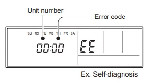
If “CO” appears in the unit number display, there is a remote control error.
Refer to the installation instruction sheet included with the remote control. If you need still need a helping hand, our previous how to repair ac remote control guide may help.
Troubleshooting at the outdoor unit LED
Make a TEST RUN in accordance with the installation instruction sheet for the indoor unit.
When a malfunction occurs in the outdoor unit, the LED on the circuit board lights to indicate the error.
Refer to the following table for the description of each error according to the LED
| LED | Error |
|---|---|
| 1 flash | Communication error (Indoor unit – Outdoor unit) |
| 2 flash | Discharge pipe temperature sensor |
| 3 flash | Outdoor heat exchanger temperature (outlet) sensor |
| 4 flash | Outdoor temperature sensor |
| 5 flash | Outdoor heat exchanger temperature (mid) sensor |
| 6 flash | Discharge pipe temperature abnormal |
| 7 flash | Compressor temperature sensor |
| 8 flash | Heat sink temperature sensor |
| 9 flash | Pressure switch abnormal |
| 10 flash | Compressor temperature abnormal |
| 12 flash | IPM error |
| 13 flash | Compressor rotor position cannot detect |
| 14 flash | Compressor cannot operate |
| 15 flash | Outdoor fan abnormal (upper fan) |
| 16 flash | Outdoor fan abnormal (lower fan) |
| 5 sec on/ 0.1 sec off repeat | PAM voltage abnormality |
| 5 sec on/ 1 sec off repeat | Protect operation |
| 5 sec on/ 2 sec off repeat | PFC surge protection (permanent stop) |
| 5 sec on/ 5 sec off repeat | Fan malfunction |
| 2 sec on/ 2 sec off repeat | CT abnormality |
| 2 sec on/ 5 sec off repeat | Compressor temperature protection (permanent stop) |
| 1 sec on/ 1 sec off repeat | Pump down operation |
| 0.5 sec on/ 0.5 sec off repeat | Current surge protection |
| 0.1 sec on/ 0.1 sec off repeat | Thermistor malfunction |
| 0.1 sec on/ 2 sec off repeat | Compressor position detection malfunction |
| off | No error |
Troubleshooting at the indoor unit display
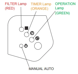
Error is displayed on the wired and wireless remote control. Lamps show error contents by flashing as follows.
| OPERATION Lamp | TIMER Lamp | FILTER Lamp | Possible Errors |
| off | 2 times | off | Indoor signal error |
| off | 3 times | off | Indoor signal error |
| off | 4 times | off | Indoor signal error |
| off | 5 times | off | Indoor signal error |
| off | 8 times | off | Wired remote controller abnormal |
| 2 times | 2 times | off | Indoor room temperature sensor error |
| 2 times | 3 times | off | Indoor heat exchanger temperature sensor (middle) error |
| 2 times | 4 times | off | Indoor heat exchanger temperature sensor (inlet) error |
| 2 times | 6 times | off | Float switch operated |
| 3 times | 2 times | off | Outdoor discharge pipe temperature sensor error |
| 3 times | 3 times | off | Outdoor heat exchanger temperature sensor (outlet) error |
| 3 times | 4 times | off | Outdoor temperature sensor error |
| 3 times | 7 times | off | Heat sink thermistor (Inverter) error |
| 3 times | 8 times | off | Compressor temperature sensor error |
| 3 times | off | 2 times | 2-way valve temperature sensor error |
| 3 times | off | 3 times | 3-way valve temperature sensor error |
| 3 times | off | 4 times | Outdoor heat exchanger temperature sensor (middle) error |
| 3 times | off | 5 times | Heat sink thermistor (P.F.C) error |
| 4 times | 2 times | off | Indoor manual auto switch abnormal |
| 4 times | 4 times | off | Power supply frequency detection error |
| 5 times | 2 times | off | IPM protection |
| 5 times | 3 times | off | CT error |
| 5 times | 5 times | off | Compressor location error |
| 5 times | 6 times | off | Outdoor fan error |
| 5 times | 7 times | off | Connected indoor unit abnormal |
| 5 times | 8 times | off | Outdoor unit computer communication error |
| 5 times | off | 2 times | Inverter error |
| 6 times | 2 or 3 times | off | Indoor fan abnormal |
| 7 times | 2 times | off | Discharge temperature error |
| 7 times | 3 times | off | Excessive high pressure protection on cooling |
| 7 times | 4 times | off | 4-way valve abnormal |
| 7 times | 5 times | off | Pressure switch abnormal, Pressure sensor abnormal |
| 7 times | 6 times | off | Compressor temperature error |
| 7 times | 7 times | off | Low pressure error |
| 8 times | 2 or 3 times | off | Active filter abnormal |
| 8 times | 4 times | off | PFC circuit error |
| 8 times | 6 times | off | P.F.C PCB error |
| 9 times | 2 times | off | Refrigerant circuit address set-up error |
| 9 times | 3 times | off | Master unit, Slave unit set-up error |
| 9 times | 4 times | off | Connected indoor number set-up error |
Flash means “0.5 second on / 0.5 second off”.
Fujitsu air conditioner error code 00
Wired remote controller abnormal.
Fujitsu air conditioner error code 01
Indoor signal error.
Fujitsu air conditioner error code 02
Indoor room temperature sensor error
Fujitsu air conditioner error code 04
Indoor heat exchanger temperature sensor (middle) error
Fujitsu air conditioner error code 06
Outdoor heat exchanger thermistor (outlet) error.
Fujitsu air conditioner error code 09
Float switch operated.
Fujitsu air conditioner error code 12
Indoor fan abnormal.
Fujitsu air conditioner error code 13
Serial forward transfer error.
Fujitsu air conditioner error code 15
Compressor temperature sensor error.
Fujitsu air conditioner error code 16
Pressure switch abnormal, Pressure sensor abnormal.
Fujitsu air conditioner error code 17
IPM protection.
Fujitsu air conditioner error code 18
CT error
Fujitsu air conditioner error code 19
Active filter abnormal.
Fujitsu air conditioner error code 20
Indoor manual auto switch abnormal.
Fujitsu air conditioner error code 24
Excessive high pressure protection on cooling.
Fujitsu air conditioner error code 25
P.F.C. circuit error.
Fujitsu air conditioner error code 26
Communication error ( Main PCB to Display PCB )
Fujitsu air conditioner error code 27
Communication error ( Display PCB to Main PCB )
Fujitsu air conditioner error code 28
Indoor heat exchanger thermistor (inlet) error.
Fujitsu air conditioner error code 29
Outdoor heat exchanger thermistor (middle) error.
Fujitsu air conditioner error code 30
Refrigerant circuit address set-up error.
Fujitsu air conditioner error code 31
Master unit, Slave unit set-up error.
Fujitsu air conditioner error code 32
Connected the indoor number set-up error.
Fujitsu air conditioner error code 33
P.F.C. PCB error.
Fujitsu air conditioner error code 0A
Outdoor temperature sensor error.
Fujitsu air conditioner error code 0C
Outdoor discharge pipe temperature sensor error.
Fujitsu air conditioner error code 0E
Heat sink thermistor (Inverter) error.
Fujitsu air conditioner error code 0F
Discharge temperature error.
Fujitsu air conditioner error code 1A
Compressor location error.
Fujitsu air conditioner error code 1B
Outdoor fan error.
Fujitsu air conditioner error code 1C
Outdoor unit computer communication error.
Fujitsu air conditioner error code 1D
2-way valve temperature sensor error.
Fujitsu air conditioner error code 1E
3-way valve temperature sensor error.
Fujitsu air conditioner error code 1F
Connected indoor unit abnormal.
Fujitsu air conditioner error code 2A
Power supply frequency detection error.
Fujitsu air conditioner error code 2B
Compressor temperature error.
Fujitsu air conditioner error code 2C
4-way valve abnormal
Fujitsu air conditioner error code 2D
Heat sink thermistor (P.F.C.) error.
Fujitsu air conditioner error code 2E
Inverter error.
Fujitsu air conditioner error code 2F
Low pressure error.
General Troubleshooting
1. Fujitsu AC doesn’t operate immediately
Possible causes:
- If the unit is stopped and then immediately started again, the compressor will not operate for about 3 minutes, in order to prevent fuse blowouts.
- Whenever the Power Supply Plug is disconnected and then reconnected to a power outlet, the protection circuit will operate for about 3 minutes, preventing unit operation during that period.
2. Fujitsu AC have noise
Possible causes:
- During operation and immediately after stopping the unit, the sound of water flowing in the air conditioner’s piping may be heard. Also, noise may be particularly noticeable for about 2 to 3 minutes after starting operation (sound of coolant flowing).
- During operation, a slight squeaking sound may be heard. This is the result of minute expansion and contraction of the front cover due to temperature changes.
- During Heating operation, a sizzling sound may be heard occasional. This sound is produced by the Automatic Defrosting operation
3. Fujitsu AC have smell
Possible cause:
- Some smell may be emitted from the indoor unit. This smell is the result of room smells (furniture, tobacco, etc.) which have been taken into the air conditioner.
4. Mist or steam are emitted in Fujitsu AC
Possible causes:
- During Cooling or Dry operation, a thin mist may be seen emitted from the indoor unit. This results from the sudden Cooling of room air by the air emitted from the air conditioner, resulting in condensation and misting.
- During Heating operation, the outdoor unit’s fan may stop, and steam may be seen rising from the unit. This is due to Automatic Defrosting operation.
5. Fujitsu AC airflow is weak or stops
Possible causes:
- When Heating operation is started, fan speed is temporarily very low, to allow internal parts to warm up.
- During Heating operation, if the room temperature rises above the thermostat setting, the outdoor unit will stop, and the indoor unit will operate at very low fan speed. If you wish to warm the room further, set the thermostat for a higher setting.
- During Heating operation, the unit will temporarily stop operation (between 7 and 15 minutes) as the Automatic Defrosting mode operates. During Automatic Defrosting operation, the OPERATION Indicator Lamp will flash.
- The fan may operate at very low speed during Dry operation or when the unit is monitoring the room’s temperature.
- During SUPER QUIET operation, the fan will operate at very low speed.
- In the monitor AUTO operation, the fan will operate at very low speed.
6. Water is produced from Fujitsu AC outdoor unit
Possible cause:
- During Heating operation, water may be produced from the outdoor unit due to Automatic Defrosting operation.
7. Fujitsu AC doesn’t operate at all
Possible causes:
- Is the Power Supply Plug disconnected its outlet?
- Has there been a power failure?
- Has a fuse blown out, or a circuit breaker been tripped?
- Is the timer operating?
7. Fujitsu AC not cool
Possible causes:
- Is the Air Filter dirty?
- Air the air conditioner’s intake grille or outlet port blocked?
- Did you adjust the room temperature settings (thermostat) correctly?
- Is there a window or door open?
- In the case of Cooling operation, is a window allowing bright sunlight to enter? (Close the curtains.)
- In the case of Cooling operation, are there heating apparatus and computers inside the room, or are there too many people in the room?
7. Fujitsu AC operates differently from the Remote Controller’s setting
Possible causes:
- Are the Remote Controller’s batteries dead?
- Are the Remote Controller’s batteries loaded properly?
How to clean Fujitsu air conditioner intake grille?
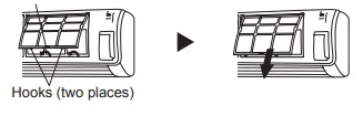
1. Remove the Intake Grille
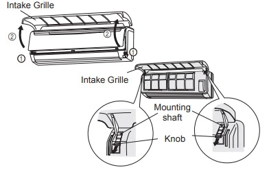
- Place your fingers at both lower ends of the grille panel, and lift forward; if the grille seems to catch partway through its movement, continue lifting upward to remove.
- Pull past the intermediate catch and open the Intake Grille wide so that it become horizontal.
2. Clean with water
Remove dust with a vacuum cleaner; wipe the unit with warm water, then dry with a clean, soft cloth.
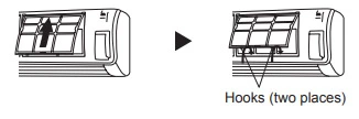
3. Replace the Intake Grille
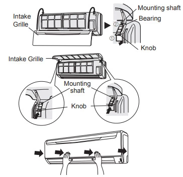
- Pull the knobs all the way.
- Hold the grille horizontal and set the left and right mounting shafts into the bearings at the top of the panel.
- Press the place where the arrow on the diagram indicates and close the Intake Grille.
How to clean Fujitsu air conditioner air filter?
Total Time: 30 minutes
-
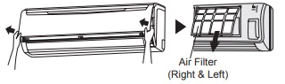
Open the Intake Grille, and remove the air filter.

Lift up the air filter’s handle, disconnect the two lower tabs, and pull out air filter handle.
-
Remove dust with a vacuum cleaner or by washing.
After washing, allow to dry thoroughly in a shaded place.
-
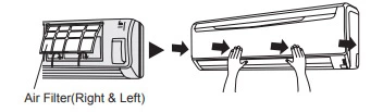
Replace the Air Filter and close the Intake Grille.

Align the sides of the air filter with the panel, and push in fully, making sure the two lower tabs are returned properly to their holes in the panel. Close the Intake Grille.
- Dust can be cleaned from the air filter either with a vacuum cleaner, or by washing the filter in a solution of mild detergent and warm water. If you wash the filter, be sure to allow it to dry thoroughly in a shady place before reinstalling.
- If dirt is allowed to accumulate on the air filter, air flow will be reduced, lowering operating efficiency and increasing noise.
- During periods of normal use, the Air Filters should be cleaned every two weeks.
How to replace Fujitsu air conditioner air filter?
Replace filters with the following components (purchased separately).
- POLYPHENOL CATECHIN AIR CLEANING FILTER : UTR-FA13-1
- Negative air ions deodorizing filter: UTR-FA13-2
1. Open the Intake Grille and remove the Air filters.
2. Replace them by two new Air cleaning filters.
- Remove the old air cleaning filters in reverse order of their installation.
- Install in the same way as for installation of the air cleaning filter set.
3. Install the two Air filters and close the Intake Grille
In regard to the Fujitsu air conditioner air filter:
POLYPHENOL CATECHIN AIR CLEANING FILTER (one sheet)
- The Air Cleaning Filters are disposable filters. (They can not be washed and reused.)
- For storage of the Air Cleaning Filters, use the filters as soon as possible after the package has been opened. (The air cleaning effect decreases when the filters are left in the opened package)
- Generally, the filters should be exchanged about every three months.
Negative air ions deodorizing filter (one sheet) – light blue
- The filters should be exchanged about every three years so as to maintain the deodorizing effect.
- Filter frame is not a one-off product.
Maintenance of Deodorizing Filters
In order to maintain the deodorizing effect, please clean the filter in the follow way once three months.
- Remove the deodorizing filter.
- Clean with water and dry in the air.
- Reinstall the deodorizing filter.
Hope that this guide help you. If still need help in aircon servicing, please feel free to get in touch.
Коды ошибок промышленных кондиционеров LG.
Внутренний блок:
01 – датчик температуры воздуха короткозамкнут или обрыв в цепи;
02 – датчик температуры испарителя короткозамкнут или обрыв в цепи;
03 – плохое соединение внутреннего блока с проводным пультом управления;
04 – ошибка дренажного насоса (помпы) или поплавкового датчика уровня конденсата;
05 – ошибка в межблочном соединении внешнего и внутреннего блоков;
06 – датчик температуры наружного блока короткозамкнут или обрыв в цепи;
07 – внутренние блоки мультиситсемы включены на разные режимы работы;
HL – та же ошибка, что и 04, поплавковый датчик разомкнут;
CL – установлен детский замок, для включения нажмите Timer & Min Buttons 3 секунды;
Po – установлен режим jet cool, для выхода нажмите кнопку jet cool
Внешний блок:
21 – перегрузка компрессора по току;
22 – ток компрессора более 14 А;
23 – напряжение постоянного тока ниже 140 В; (не напряжение питания, а после модуля преобразования)
24 – ошибка по высокому/низкому давлению, датчики давления разомкнуты;
25 – напряжение питания выше/ниже нормального значения;
26 – DC Compressor Position;
27 – ошибка PSC (реактор, катушка индуктивности);
28 – DC Link High Volts;
32 – Высокая температура нагнетательной трубы (INV);
33 – Высокая температура нагнетательной трубы (Cons.);
40 – короткое замыкание CT;
41 – датчик температуры D-Pipe замкнут/оборван (INV);
44 – датчик температуры наружного воздуха замкнут/оборван;
45 – датчик температуры конденсатора замкнут/оборван;
46 – датчик на всасывающей трубке замкнут/оборван;
47 – D-pipe датчик замкнут/оборван;
48 – D-pipe датчик и датчик температуры воздуха отсутствуют/оборваны;
51 – комбинированная перегрузка по мощности;
52 – ошибка соединения (main micom-sub micom);
53 – ошибка соединения (внутренний-наружный блоки);
54 – для систем с 3-хфазным питанием, неправильная последовательность фаз,поменять фазу;
60 -ошибка EEPROM (внутренняя энергонезависимая память)
61 -высокая температура трубки конденсатора (конденсера)
62 -высокая температура радиатора(скорее всего имеется в виду радиатор охлаждения силового модуля инвертора)
63 -низкая температура конденсатора
65 -датчик температуры радиатора замкнут/оборван
67 -заблокирован наружный BLDC (безколлекторный электродвигатель постоянного тока) вентилятор
105 -нет связи между главной платой управления и платой управления вентилятором
Коды ошибок всех настенных кондиционеров LG, в том числе серии Art Cool
C1 или CH1 – внутренний датчик температуры воздуха короткозамкнут или обрыв в цепи;
C2 или CH2 – датчик температуры испарителя короткозамкнут или обрыв в цепи;
C4 или CH4 – температурный датчик конденсатора короткозамкнут или обрыв в цепи;
C5 или CH5 – соединение между внешним и внутренним блоками;
C6 или CH6 – превышен ток в цепи инверторного модуля;
C7 или CH7 – превышен ток компрессора;
C8 или CH8 – не вращается вентилятор внутреннего блока;
C9 или CH9 – не вращается вентилятор внешнего блока;
C10 или CH-10 – неисправен терморезистор контроля температуры корпуса компрессора сплит системы (обрыв или короткое замыкание)
CA – температура нагнетания выше 130 0С;
CC – ошибка EEPROM (внутренняя энергонезависимая память);
CD – ошибка в инверторном модуле;
CE
Po – система находится в энергосберегающем режиме, ошибки нет;
Lo – система находится в режиме тестирования,ошибки нет;
Если кода ошибки нет,а моргают светодиодные индикаторы на панели необходимо скачать полную версию кода ошибок, там же находится график зависимости сопротивления температурного датчика от температуры.
Все коды ошибок кондиционеров LG
|
Код неисправности |
Расшифровка кода ошибки |
|
00 |
Text the 1, 2 or 3 digit fault code number only. I.e. If you see fault code CH07 on your indoor unit or R/Controller, only type 7 or 07 in your text message. |
|
01 |
Indoor unit return air sensor fault. Disconnect sensor from PCB and measure resistance. 8 kOhm at 30C and 13 kOhm at 20C if not replace sensor |
|
1 |
Indoor unit return air sensor fault. Disconnect sensor from PCB and measure resistance. 8 kOhm at 30C and 13 kOhm at 20C if not replace sensor |
|
02 |
Indoor Pipe Sensor or Outdoor Sensor Assy fault, Open or Short. Disconnect from PCB and measure resistance. Air sensor = 10 kOhm at 25C, Pipe sensor = 5 kOhm at 25C. If not replace sensor. |
|
2 |
Indoor Pipe Sensor or Outdoor Sensor Assy fault, Open or Short. Disconnect from PCB and measure resistance. Air sensor = 10 kOhm at 25C, Pipe sensor = 5 kOhm at 25C. If not replace sensor. |
|
03 |
Remote controller comms error. Check wired correctly, if so check dipswitch in RC. Set to Sg for 1 unit, or Gr for group then reset power |
|
3 |
Remote controller comms error. Check wired correctly, if so check dipswitch in RC. Set to Sg for 1 unit, or Gr for group then reset power |
|
04 |
RAC Product = Heat Sink Sensor Error, Open/Short Cct or over 95C. Commercial Product = Condensate pump float switch risen. Check drain pan is empty, check pump is working OK. If no pump check blue jumper plug is inserted in socket CN Float. |
|
4 |
RAC Product = Heat Sink Sensor Error, Open/Short Cct or over 95C. Commercial Product = Condensate pump float switch risen. Check drain pan is empty, check pump is working OK. If no pump check blue jumper plug is inserted in socket CN Float. |
|
05 |
Comms Error, check your wiring, remove external pumps. Split/Multi – check volts from terminal N to 3 = 0 – 65 Vdc, Multi V – 4 Vdc terminals 3 and 4 |
|
5 |
Comms Error, check your wiring, remove external pumps. Split/Multi – check volts from terminal N to 3 = 0 – 65 Vdc, Multi V – 4 Vdc terminals 3 and 4 |
|
06 |
Indoor unit coil sensor fault. Disconnect from PCB measure resistance. 10 kOhm at 10C and 4 kOhm at 30C. if not replace sensor. Split = text 21 |
|
6 |
Indoor unit coil sensor fault. Disconnect from PCB measure resistance. 10 kOhm at 10C and 4 kOhm at 30C. if not replace sensor. Split = text 21 |
|
07 |
Multi Splits and Multi V = indoor unit is set to run in a different mode from the master indoor unit. Set ALL indoor units to cooling or ALL to heating to clear. Splits = Compressor Over Current (CT2), also see Code 06. |
|
7 |
Multi Splits and Multi V = indoor unit is set to run in a different mode from the master indoor unit. Set ALL indoor units to cooling or ALL to heating to clear. Splits = Compressor Over Current (CT2), also see Code 06. |
|
RAC Indoor unit BLDC Fan problem. This is caused by the Indoor fan being locked. Check fan motor is plugged in correctly, Electrically & Mechanically sound. |
|
|
08 |
Check the fan motor turns freely, check the AC Voltage supplied to the fan motor, this will vary from 120 V ac at low speed to 170V AC at high speed. If no |
|
Voltage is present the the PCB is faulty, if Voltage is present the fan motor will be Faulty. |
|
|
RAC Indoor unit BLDC Fan problem. This is caused by the Indoor fan being locked. Check fan motor is plugged in correctly, Electrically & Mechanically sound. |
|
|
8 |
Check the fan motor turns freely, check the AC Voltage supplied to the fan motor, this will vary from 120 V ac at low speed to 170V AC at high speed. If no |
|
Voltage is present the the PCB is faulty, if Voltage is present the fan motor will be Faulty. |
|
|
09 |
Split = Outdoor unit fan problem. Check Outdoor fan motor is plugged in, Electrically & Mechanically sound, if not replace motor, otherwise replace PCB. Multi V = Indoor unit EEPROM error – Replace the indoor unit PCB, and then make sure to do Auto addressing and input the address of central control. |
|
9 |
Split = Outdoor unit fan problem. Check Outdoor fan motor is plugged in, Electrically & Mechanically sound, if not replace motor, otherwise replace PCB. Multi V = Indoor unit EEPROM error – Replace the indoor unit PCB, and then make sure to do Auto addressing and input the address of central control. |
|
10 |
RAC Product: Compressor discharge sensor fault. Disconnect from PCB measure resistance 237 kOhm at 20°C, 168 kOhm at 30C. Multi Fdx & Multi V text 8 |
|
11 |
Multi V indoor unit not connected to an outdoor unit. Check comms wiring is correct, and check initialisation has been carried out correctly |
|
12 |
RAC Product = EEPROM Sum Check Error, text 60 for help. |
|
13 |
RAC Product = PSC (Reactor) Error, text 27 for help. |
|
14 |
RAC Product = Compressor Phase Current Error |
|
15 |
no such fault code Text 1, 2 or 3 digit fault code number only. If you see fault code CH07 only type 7 in your text message |
|
16 |
no such fault code Text 1, 2 or 3 digit fault code number only. If you see fault code CH07 only type 7 in your text message |
|
17 |
no such fault code Text 1, 2 or 3 digit fault code number only. If you see fault code CH07 only type 7 in your text message |
|
18 |
no such fault code Text 1, 2 or 3 digit fault code number only. If you see fault code CH07 only type 7 in your text message |
|
19 |
no such fault code Text 1, 2 or 3 digit fault code number only. If you see fault code CH07 only type 7 in your text message |
|
20 |
no such fault code Text 1, 2 or 3 digit fault code number only. If you see fault code CH07 only type 7 in your text message |
|
21 |
Inverter compressor run current high. Check compressor windings all equal 1 to 4 Ohms, Check to earth 50 MOhm minimum, check run current |
|
22 |
Inverter compressor run current high. Check compressor windings all equal 1 to 4 Ohms . Check to earth 50 MOhm minimum, check run current |
|
23 |
Inverter dc voltage low. Check dc voltage of capacitors 300 Vdc for 1Ph and 600 Vdc for 3Ph. If OK change outdoor inverter PCB |
|
24 |
Splits and Multi Splits = High or low pressure trip. Low at 1 bar High at 35 bar check pressures. Multi V = High pressure trip. |
|
25 |
Check power supply voltage to the outdoor unit is correct (1ph ?220 Vac ±10% or 3ph ?380 Vac ±10%). If OK, check fuses, if fuses are OK replace outdoor main PCB |
|
26 |
Inverter compressor seized. Check compressor windings all equal resistance 1 to 4 Ohms, check to earth 50 MOhm minimum, check run current and Inverter outputs |
|
27 |
Inverter current irregularity. Check inverter PCB, check reactor connections and its resistance is less than 1 ohm. |
|
28 |
Inverter dc voltage too high. Check dc voltage of capacitors 300 Vdc for 1Ph and 600 Vdc for 3Ph. If OK change outdoor inverter PCB |
|
29 |
no such fault code Text 1, 2 or 3 digit fault code number only. If you see fault code CH07 only type 7 in your text message |
|
30 |
no such fault code Text 1, 2 or 3 digit fault code number only. If you see fault code CH07 only type 7 in your text message |
|
31 |
no such fault code Text 1, 2 or 3 digit fault code number only. If you see fault code CH07 only type 7 in your text message |
|
32 |
Inverter compressor discharge temperature too high. If over 105°C, check refrigerant charge |
|
33 |
Excessive rise of standard compressor discharge temperature. If over 105°C check refrigerant charge |
|
34 |
Excessive high pressure rise, over 35 bar at HP sensor. Check pressures, check coils, and filters are clean check for OFN in system pipework |
|
35 |
Excessive low pressure drop under 1 Bar at LP sensor. Check pressures, and check service valves open |
|
36 |
no such fault code Text 1, 2 or 3 digit fault code number only. If you see fault code CH07 only type 7 in your text message |
|
37 |
no such fault code Text 1, 2 or 3 digit fault code number only. If you see fault code CH07 only type 7 in your text message |
|
38 |
no such fault code Text 1, 2 or 3 digit fault code number only. If you see fault code CH07 only type 7 in your text message |
|
39 |
no such fault code Text 1, 2 or 3 digit fault code number only. If you see fault code CH07 only type 7 in your text message |
|
40 |
Inverter ac current abnormal. Check compressor windings all equal resistance 1 to 4 Ohms, check to earth 50 MOhm minimum, check run current and inverter outputs |
|
41 |
Inverter compressor discharge sensor fault. Disconnect from PCB measure resistance 237 kOhm at 20°C and 168 kOhm at 30°C. |
|
42 |
Low pressure sensor fault. Check dc voltage between white and black cable on plug. Multi V: 1 Vdc = 4 bar up to 5 Vdc = 32 bar |
|
43 |
High pressure sensor fault. Check dc voltage between white and black cable on plug. Multi V: 1 Vdc = 8 bar up to 2.5 Vdc = 37 bar |
|
44 |
Outdoor unit air sensor fault. Disconnect from PCB and measure resistance. 8 kOhm at 30C and 13 kOhm at 20C. If OK replace PCB, if not replace sensor |
|
45 |
Outdoor unit coil sensor fault. Disconnect from PCB measure resistance. 10 kOhm at 10°C and 4 kOhm at 30°C. If OK replace PCB, if not replace sensor |
|
46 |
Outdoor unit suction sensor fault. Disconnect from PCB and measure resistance. 10 kOhm at 10°C and 4 kOhm at 30°C. If OK replace PCB, if not replace sensor |
|
47 |
Compressor discharge sensor fault. Disconnect from PCB measure resistance. 237 kOhm at 20°C and 168 kOhm at 30°C. If OK replace PCB, if not replace sensor |
|
48 |
Split/Multi Split = Outdoor unit discharge and air sensor both unplugged. Multi V = Outdoor unit coil sensor. Text 45 for diagnostics |
|
49 |
Check power supply voltage to the outdoor unit is correct (1ph ?220 Vac ±10% or 3ph ?380 Vac ±10%). If OK check fuses, if fuses OK, replace outdoor main PCB |
|
50 |
no such fault code Text 1, 2 or 3 digit fault code number only. If you see fault code CH07 only type 7 in your text message |
|
51 |
Unit mismatch. Check model number of units do not exceed maximum. Multi V – also check Sub outdoor unit dipswitch settings |
|
52 |
Communication error between inverter PCB and main outdoor unit PCB. Check wiring fuses and LEDs . If OK either inverter or main PCB defective |
|
53 |
Comms error indoor to outdoor unit. Check your wiring . Split and Multi – check voltage from terminal N to 3 = 0 – 65 Vdc, Multi V – 4 Vdc terminals 3 and 4 |
|
54 |
Reverse or open phase. Check all 3 phases are present and correct. If correct voltage appears at all three phases, swap any two to cure the fault |
|
55 |
no such fault code Text 1, 2 or 3 digit fault code number only. If you see fault code CH07 only type 7 in your text message |
|
56 |
no such fault code Text 1, 2 or 3 digit fault code number only. If you see fault code CH07 only type 7 in your text message |
|
57 |
Comms error between outdoor main PCB and inverter PCB. Check wiring fuses and LEDs are lit. If OK either inverter or main PCB defective |
|
58 |
no such fault code Text 1, 2 or 3 digit fault code number only. If you see fault code CH07 only type 7 in your text message |
|
59 |
no such fault code Text 1, 2 or 3 digit fault code number only. If you see fault code CH07 only type 7 in your text message |
|
60 |
Outdoor unit PCB EEPROM failure, try removing EEPROM and refitting if removable (possible contact fault), otherwise replace PCB if the EEPROM is non-removable. |
|
61 |
Condenser coil over 65°C. Check coil and filters are clean and free from debris, and airflow is OK. Check system pressures for non-condesables |
|
62 |
Inverter over 85°C. Check air flow across heat sink, check inverter tight to heatsink use thermal paste. Multi V – check inverter cooling fan |
|
63 |
Multi F(DX) – “Cond. Pipe Sensor Temp. Low” (opposite to Error Code 61). Check Temperature/Resistance reading and replace sensor if found to be faulty. If sensor okay, check for cause of low temperature and rectify. |
|
64 |
no such fault code Text 1, 2 or 3 digit fault code number only. If you see fault code CH07 only type 7 in your text message |
|
65 |
Outdoor unit inverter fin temperature sensor fault. Disconnect from PCB measure resistance. 8 kOhm at 30°C and 13 kOhm at 20°C |
|
67 |
Outdoor Fan Motor siezed, or rotation sensing circuit failure. Check motor for mechanical and/or electrical failure, if okay replace pcb. |
|
100 |
Excessive discharge temperature rise 105°C Sub condenser 1 standard compressor. Check refrigerant |
|
101 |
Excessive discharge temperature rise 105°C Sub condenser 1 standard compressor. Check refrigerant |
|
102 |
Excessive discharge temperature rise 105°C Sub condenser 2 standard compressor. Check refrigerant |
|
103 |
Excessive discharge temperature rise 105°C Sub condenser 2 standard compressor. Check refrigerant |
|
104 |
Communication error between Main and Sub outdoor units. Check comms wiring and power to all outdoor units |
|
105 |
Communication error between outdoor main PCB and fan PCB. Check plug connections and LEDs. If OK, replace either main or fan PCB |
|
106 |
Outdoor unit fan motor high current. Check fans rotate freely, and are connected correctly |
|
107 |
Outdoor unit low voltage to fan PCB. Check 300 Vdc supply, check fuses and plug connections. If OK, replace fan PCB |
|
108 |
Communication error between outdoor main PCB, and fan PCB. Check plug connections and LEDs. If OK replace either main or fan PCB |
|
109 |
Sub 1 excessive rise of high pressure. Check pressures, check for non condensables, check heat exchanger coil is free from debris |
|
110 |
Sub 1 reverse or open phase. Check all 3 phases are present and correct. If correct voltage appears at all three phases, swap any two to cure the fault |
|
111 |
Communication error between Main and Sub outdoor units. Check comms wiring and power to all outdoor units |
|
113 |
Main outdoor unit liquid pipe sensor fault. Disconnect from PCB and measure resistance. 10 kOhm at 10°C and 4 kOhm at 30°C |
|
114 |
Main outdoor unit Subcool inlet sensor fault. Disconnect from PCB and measure resistance. 10 kOhm at 10°C and 4 kOhm at 30°C |
|
115 |
Main outdoor unit Subcool outlet sensor fault. Disconnect from PCB and measure resistance. 10 kOhm at 10°C and 4 kOhm at 30°C |
|
116 |
Sub 1 high pressure sensor fault. Check dc voltage between white and black cable on plug. Multi V: 1 Vdc = 8 bar up to 2.5 Vdc = 37 bar |
|
117 |
Sub 1 low pressure sensor fault. Check dc voltage between white and black cable on plug. Multi V: 1 Vdc = 4 bar up to 5 Vdc = 32 bar |
|
118 |
Sub 1 outdoor unit air sensor fault. Disconnect from PCB and measure resistance. 8 kOhm at 30°C and 13 kOhm at 20°C. If OK replace PCB, if not replace sensor |
|
120 |
Sub 1 outdoor unit suction sensor fault. Disconnect from PCB and measure resistance. 10 kOhm at 10°C and 4 kOhm at 30°C. if not replace sensor |
|
121 |
Sub 1 compressor 1 discharge sensor fault. Disconnect from PCB measure resistance 237 kOhm at 20°C and 168 kOhm at 30°C. if not replace sensor |
|
122 |
Sub 1 compressor 2 discharge sensor fault. Disconnect from PCB measure resistance 237 kOhm at 20°C and 168 kOhm at 30°C. if not replace sensor |
|
123 |
Sub 1 outdoor unit coil sensor A fault. Disconnect from PCB measure resistance. 10 kOhm at 10°C and 4 kOhm at 30°C. If OK replace PCB, if not replace sensor |
|
124 |
Sub 1 outdoor unit coil sensor B fault. Disconnect from PCB measure resistance. 10 kOhm at 10°C and 4 kOhm at 30°C. If OK replace PCB, if not replace sensor |
|
125 |
Sub 1 outdoor unit liquid pipe sensor fault. Disconnect from PCB and measure resistance. 10 kOhm at 10°C and 4 kOhm at 30°C |
|
126 |
Sub 1 outdoor unit Subcool inlet sensor fault. Disconnect from PCB and measure resistance. 10 kOhm at 10°C and 4 kOhm at 30°C |
|
127 |
Sub 1 outdoor unit Subcool outlet sensor fault. Disconnect from PCB and measure resistance. 10 kOhm at 10°C and 4 kOhm at 30°C |
|
128 |
Sub 2 high pressure sensor fault. Check dc voltage between white and black cable on plug. Multi V: 1 Vdc = 8 bar up to 2.5 Vdc = 37 bar |
|
129 |
Sub 2 low pressure sensor fault. Check dc voltage between white and black cable on plug. Multi V: 1 Vdc = 4 bar up to 5 Vdc = 32 bar |
|
130 |
Sub 2 outdoor unit air sensor fault. Disconnect from PCB and measure resistance. 8 kOhm at 30°C and 13 kOhm at 20°C. If OK replace PCB, if not replace sensor |
|
132 |
Sub 2 outdoor unit suction sensor fault. Disconnect from PCB and measure resistance. 10 kOhm at 10°C and 4 kOhm at 30°C.if not replace sensor |
|
133 |
Sub 2 compressor 1 discharge sensor fault. Disconnect from PCB measure resistance 237 kOhm at 20°C and 168kOhm at 30°C. if not replace sensor |
|
134 |
Sub 2 compressor 2 discharge sensor fault. Disconnect from PCB measure resistance 237 kOhm at 20°C and 168kOhm at 30°C.if not replace sensor |
|
135 |
Sub 2 outdoor unit coil sensor A fault. Disconnect from PCB measure resistance. 10 kOhm at 10°C and 4 kOhm at 30°C. If OK replace PCB, if not replace sensor |
|
136 |
Sub 2 outdoor unit coil sensor B fault. Disconnect from PCB measure resistance. 10 kOhm at 10°C and 4 kOhm at 30°C. If OK replace PCB, if not replace sensor |
|
137 |
Sub 2 outdoor unit liquid pipe sensor fault. Disconnect from PCB and measure resistance. 10 kOhm at 10°C and 4 kOhm at 30°C |
|
138 |
Sub 2 outdoor unit Subcool inlet sensor fault. Disconnect from PCB and measure resistance. 10 kOhm at 10°C and 4 kOhm at 30°C |
|
139 |
Sub 2 outdoor unit Subcool outlet sensor fault. Disconnect from PCB and measure resistance. 10 kOhm at 10°C and 4 kOhm at 30°C |
|
140 |
Sub 2 excessive rise of high pressure. Check pressures, check for non condensables, check heat exchanger coil is free from debris |
|
141 |
Sub 2 reverse or open phase. Check all 3 phases are present and correct. If correct voltage appears at all three phases, swap any two to cure the fault |
|
142 |
Communication error between Main and Sub outdoor units. Check comms wiring and power to all outdoor units |
|
143 |
Sub 1 excessive rise of high pressure. Check pressures, check for non condensables, check heat exchanger coil is free from debris |
|
144 |
Sub 1 excessive drop of low pressure. Check pressures, check for non condensables, check heat exchanger coil is free from debris |
|
145 |
Sub 2 excessive rise of high pressure. Check pressures, check for non condensables, check heat exchanger coil is free from debris |
|
146 |
Sub 2 excessive drop of low pressure. Check pressures, check for non condensables, check heat exchanger coil is free from debris |
|
147 |
Sub 1 check power supply voltage to the outdoor unit is correct (1ph 220 Vac ±10% or 3ph 380 Vac ±10%).check fuses, if fuses OK replace outdoor main PCB |
|
148 |
Sub 1 check power supply voltage to the outdoor unit is correct (1ph 220 Vac ±10% or 3ph 380 Vac ±10%). check fuses, if fuses OK replace outdoor main PCB |
|
149 |
Sub 2 check power supply voltage to the outdoor unit is correct (1ph 220 Vac ±10% or 3ph 380 Vac ±10%). check fuses, if fuses OK replace outdoor main PCB |
|
150 |
Sub 2 check power supply voltage to the outdoor unit is correct (1ph 220 Vac ±10% or 3ph 380 Vac ±10%). check fuses, if fuses OK replace outdoor main PCB |
|
151 |
Faulty 4 way valve. Check solenoid coil and output from PCB. If OK, mechanical failure. |
|
152 |
Excessive discharge temperature rise 105°C Sub condenser 2 standard compressor. Check refrigerant |
|
153 |
Excessive discharge temperature rise 105°C Sub condenser 2 standard compressor. Check refrigerant |
|
154 |
Sub 3 excessive rise of high pressure. Check pressures, check for non condensables, check heat exchanger coil is free from debris |
|
155 |
Sub 3 reverse or open phase. Check all 3 phases are present and correct. If correct voltage appears at all three phases, swap any two to cure the fault |
|
156 |
Communication error between Main and Sub outdoor units. Check comms wiring and power to all outdoor units |
|
157 |
Sub 3 high pressure sensor fault. Check dc voltage between white and black cable on plug. Multi V: 1 Vdc = 8 bar up to 2.5 Vdc = 37 bar |
|
158 |
Sub 3 low pressure sensor fault. Check dc voltage between white and black cable on plug. Multi V: 1 Vdc = 4 bar up to 5 Vdc = 32 bar |
|
159 |
Sub 3 outdoor unit air sensor fault. Disconnect from PCB and measure resistance. 8 kOhm at 30°C and 13 kOhm at 20°C. If OK replace PCB, if not replace sensor |
|
161 |
Sub 3 outdoor unit suction sensor fault. Disconnect from PCB and measure resistance. 10 kOhm at 10°C and 4 kOhm at 30°C. if not replace sensor |
|
162 |
Sub 3 compressor 1 discharge sensor fault. Disconnect from PCB measure resistance 237 kOhm at 20°C and 168 kOhm at 30°C. if not replace sensor |
|
163 |
Sub 3 compressor 2 discharge sensor fault. Disconnect from PCB measure resistance 237 kOhm at 20°C and 168 kOhm at 30°C.if not replace sensor |
|
164 |
Sub 3 outdoor unit coil sensor A fault. Disconnect from PCB measure resistance. 10 kOhm at 10°C and 4 kOhm at 30°C. If OK replace PCB, if not replace sensor |
|
165 |
Sub 3 outdoor unit coil sensor B fault. Disconnect from PCB measure resistance. 10 kOhm at 10°C and 4 kOhm at 30°C. If OK replace PCB, if not replace sensor |
|
166 |
Sub 3 outdoor unit liquid pipe sensor fault. Disconnect from PCB and measure resistance. 10 kOhm at 10°C and 4 kOhm at 30°C |
|
167 |
Sub 3 outdoor unit Subcool inlet sensor fault. Disconnect from PCB and measure resistance. 10 kOhm at 10°C and 4 kOhm at 30°C |
|
168 |
Sub 3 outdoor unit Subcool outlet sensor fault. Disconnect from PCB and measure resistance. 10 kOhm at 10°C and 4 kOhm at 30°C |
|
169 |
Sub 3 excessive rise of high pressure. Check pressures, check for non condensables, check heat exchanger coil is free from debris |
|
170 |
Sub 3 excessive drop of low pressure. Check pressures, check for non condensables, check heat exchanger coil is free from debris |
|
171 |
Sub 3 check power supply voltage to the outdoor unit is correct (1ph 220 Vac ±10% or 3ph 380 Vac ±10%). check fuses, if fuses OK replace outdoor main PCB |
|
172 |
Sub 3 check power supply voltage to the outdoor unit is correct (1ph 220 Vac ±10% or 3ph 380 Vac ±10%). check fuses, if fuses OK replace outdoor main PCB |
|
173 |
Main outdoor unit standard compressor not starting. Check output from main PCB, check contactor, and check wiring connections. If OK compressor faulty |
|
174 |
Sub 1 standard compressor 1 not starting. Check output from main PCB, check contactor, and check wiring connections. If OK compressor faulty |
|
175 |
Sub 1 standard compressor 2 not starting. Check output from main PCB, check contactor, and check wiring connections. If OK compressor faulty |
|
176 |
Sub 2 standard compressor 1 not starting. Check output from main PCB, check contactor, and check wiring connections. If OK compressor faulty |
|
177 |
Sub 2 standard compressor 2 not starting. Check output from main PCB, check contactor, and check wiring connections. If OK compressor faulty |
|
204 |
Comms Error between Outdoor Unit and HR Box No1. 1. Defective connection in HR unit power supply and transmission connection 2. Wrong setting of the HR unit Rotary switch and Dip switch 3. Defective HR unit PCB |
|
208 |
Comms Error between Outdoor Unit and HR Box No2. 1. Defective connection in HR unit power supply and transmission connection 2. Wrong setting of the HR unit Rotary switch and Dip switch 3. Defective HR unit PCB |
|
212 |
Comms Error between Outdoor Unit and HR Box No3. 1. Defective connection in HR unit power supply and transmission connection 2. Wrong setting of the HR unit Rotary switch and Dip switch 3. Defective HR unit PCB |
|
240 |
Central controller wiring error. Check all comms wiring, including between controller and CNU, and IP addresses. If OK possible defective CNU |
|
241 |
Central controller data sending error. Either defective CNU or Central controller initialisation failure |
|
242 |
Central controller data receiving error. Either defective CNU or Central controller initialisation failure |
|
243 |
Central controller. Comms cable too long or picking up external electrical noise. If OK, mismatching of controllers, or defective CNU |
|
244 |
Central controller data receiving time out. Either defective CNU or Central controller initialisation failure |
|
245 |
Central controller data sending time out. Either defective CNU or Central controller initialisation failure |
|
246 |
Central controller data receiving time out. Either defective CNU or Central controller initialisation failure |
|
250 |
Central controller data receiving error. Either comms cable picking up external electrical noise, or defective CNU |
|
251 |
Central controller receiving no data. Either comms cable picking up external electrical noise, or defective CNU |
|
252 |
Central controller incorrect address error. Check addresses match, if OK either comms cable picking up external electrical noise, or defective CNU |
|
253 |
Central Controller Disconnection Error, No response from Air Conditioner. Check wiring, if OK either comms cable picking up external electrical noise, defective CNU, or Interface. |
|
C1 |
Indoor unit return air sensor fault, Open or Short. Disconnect sensor from PCB and measure resistance. 8 kOhm at 30C and 13 kOhm at 20C if not replace sensor |
|
C2 |
Indoor Pipe Sensor or Outdoor Sensor Assy fault, Open or Short. Disconnect from PCB and measure resistance. Air sensor = 10 kOhm at 25C, Pipe sensor = 5 kOhm at 25C. If not replace sensor. |
|
C4 |
RAC Product = Heat Sink Sensor Error, Open/Short Cct or over 95C. Commercial Product = Condensate pump float switch risen. Check drain pan is empty, check pump is working OK. If no pump check blue jumper plug is inserted in socket CN Float. |
|
C5 |
Comms Error, check your wiring, remove external pumps. Split/Multi – check volts from terminal N to 3 = 0 – 65 Vdc, Multi V – 4 Vdc terminals 3 and 4 |
|
C6 |
Inverter compressor run current high. Check compressor windings all equal 1 to 4 Ohms, Check to earth 50 MOhm minimum, check run current |
|
C7 |
Splits = Compressor Over Current (CT2), also see Code 06. |
|
RAC Indoor unit BLDC Fan problem. This is caused by the Indoor fan being locked. Check fan motor is plugged in correctly, Electrically & Mechanically sound. |
|
|
C8 |
Check the fan motor turns freely, check the AC Voltage supplied to the fan motor, this will vary from 120 V ac at low speed to 170V AC at high speed. If no |
|
Voltage is present the the PCB is faulty, if Voltage is present the fan motor will be Faulty. |
|
|
C9 |
Outdoor unit fan problem. Check Outdoor fan motor is plugged in, Electrically & Mechanically sound, if not replace motor, otherwise replace PCB. |
|
CA |
Compressor discharge sensor fault. Disconnect from PCB measure resistance 237 kOhm at 20°C, 168 kOhm at 30C. |
|
CC |
RAC Product = EEPROM Sum Check Error, text 60 for help. |
|
Cd |
RAC Product = PSC (Reactor) Error, text 27 for help. |
|
CE |
RAC Product = Compressor Phase Current Error |
|
CH00 |
Text the 1, 2 or 3 digit fault code number only. I.e. If you see fault code CH07 on your indoor unit or R/Controller, only type 7 or 07 in your text message. |
|
CH01 |
Indoor unit return air sensor fault. Disconnect sensor from PCB and measure resistance. 8 kOhm at 30C and 13 kOhm at 20C if not replace sensor |
|
CH02 |
Indoor Pipe Sensor or Outdoor Sensor Assy fault, Open or Short. Disconnect from PCB and measure resistance. Air sensor = 10 kOhm at 25C, Pipe sensor = 5 kOhm at 25C. If not replace sensor. |
|
CH03 |
Remote controller comms error. Check wired correctly, if so check dipswitch in RC. Set to Sg for 1 unit, or Gr for group then reset power |
|
CH04 |
RAC Product = Heat Sink Sensor Error, Open/Short Cct or over 95C. Commercial Product = Condensate pump float switch risen. Check drain pan is empty, check pump is working OK. If no pump check blue jumper plug is inserted in socket CN Float. |
|
CH05 |
Comms Error, check your wiring, remove external pumps. Split/Multi – check volts from terminal N to 3 = 0 – 65 Vdc, Multi V – 4 Vdc terminals 3 and 4 |
|
CH06 |
Indoor unit coil sensor fault. Disconnect from PCB measure resistance. 10 kOhm at 10C and 4 kOhm at 30C. if not replace sensor. Split = text 21 |
|
CH07 |
Multi Splits and Multi V = indoor unit is set to run in a different mode from the master indoor unit. Set ALL indoor units to cooling or ALL to heating to clear. Splits = Compressor Over Current (CT2), also see Code 06. |
|
RAC Indoor unit BLDC Fan problem. This is caused by the Indoor fan being locked. Check fan motor is plugged in correctly, Electrically & Mechanically sound. |
|
|
CH08 |
Check the fan motor turns freely, check the AC Voltage supplied to the fan motor, this will vary from 120 V ac at low speed to 170V AC at high speed. If no |
|
Voltage is present the the PCB is faulty, if Voltage is present the fan motor will be Faulty. |
|
|
CH09 |
Split = Outdoor unit fan problem. Check Outdoor fan motor is plugged in, Electrically & Mechanically sound, if not replace motor, otherwise replace PCB. Multi V = indoor PCB failure. Replace PCB |
|
CH10 |
RAC Product: Compressor discharge sensor fault. Disconnect from PCB measure resistance 237 kOhm at 20°C, 168 kOhm at 30C. Multi Fdx & Multi V text 8 |
|
CH11 |
Multi V indoor unit not connected to an outdoor unit. Check comms wiring is correct, and check initialisation has been carried out correctly |
|
CH12 |
no such fault code Text 1, 2 or 3 digit fault code number only. If you see fault code CH07 only type 7 in your text message |
|
CH13 |
no such fault code Text 1, 2 or 3 digit fault code number only. If you see fault code CH07 only type 7 in your text message |
|
CH14 |
no such fault code Text 1, 2 or 3 digit fault code number only. If you see fault code CH07 only type 7 in your text message |
|
CH15 |
no such fault code Text 1, 2 or 3 digit fault code number only. If you see fault code CH07 only type 7 in your text message |
|
CH16 |
no such fault code Text 1, 2 or 3 digit fault code number only. If you see fault code CH07 only type 7 in your text message |
|
CH17 |
no such fault code Text 1, 2 or 3 digit fault code number only. If you see fault code CH07 only type 7 in your text message |
|
CH18 |
no such fault code Text 1, 2 or 3 digit fault code number only. If you see fault code CH07 only type 7 in your text message |
|
CH19 |
no such fault code Text 1, 2 or 3 digit fault code number only. If you see fault code CH07 only type 7 in your text message |
|
CH20 |
no such fault code Text 1, 2 or 3 digit fault code number only. If you see fault code CH07 only type 7 in your text message |
|
CH21 |
Inverter compressor run current high. Check compressor windings all equal 1 to 4 OhmsCheck to earth 50 MOhm minimum, check run current |
|
CH22 |
Inverter compressor run current high. Check compressor windings all equal 1 to 4 Ohms . Check to earth 50 MOhm minimum, check run current |
|
CH23 |
Inverter dc voltage low. Check dc voltage of capacitors 300 Vdc for 1Ph and 600 Vdc for 3Ph. If OK change outdoor inverter PCB |
|
CH24 |
Splits and Multi Splits = High or low pressure trip. Low at 1 bar High at 35 bar check pressures. Multi V = High pressure trip. |
|
CH25 |
Check power supply voltage to the outdoor unit is correct (1ph ?220 Vac ±10% or 3ph ?380 Vac ±10%). If OK, check fuses, if fuses are OK replace outdoor main PCB |
|
CH26 |
Inverter compressor seized. Check compressor windings all equal resistance 1 to 4 Ohms, check to earth 50 MOhm minimum, check run current and Inverter outputs |
|
CH27 |
Inverter current irregularity. Check inverter PCB and reactor |
|
CH28 |
Inverter dc voltage too high. Check dc voltage of capacitors 300 Vdc for 1Ph and 600 Vdc for 3Ph. If OK change outdoor inverter PCB |
|
CH29 |
no such fault code Text 1, 2 or 3 digit fault code number only. If you see fault code CH07 only type 7 in your text message |
|
CH30 |
no such fault code Text 1, 2 or 3 digit fault code number only. If you see fault code CH07 only type 7 in your text message |
|
CH31 |
no such fault code Text 1, 2 or 3 digit fault code number only. If you see fault code CH07 only type 7 in your text message |
|
CH32 |
Inverter compressor discharge temperature too high. If over 105°C, check refrigerant charge |
|
CH33 |
Excessive rise of standard compressor discharge temperature. If over 105°C check refrigerant charge |
|
CH34 |
Excessive high pressure rise, over 35 bar at HP sensor. Check pressures, check coils, and filters are clean check for OFN in system pipework |
|
CH35 |
Excessive low pressure drop under 1 Bar at LP sensor. Check pressures, and check service valves open |
|
CH36 |
no such fault code Text 1, 2 or 3 digit fault code number only. If you see fault code CH07 only type 7 in your text message |
|
CH37 |
no such fault code Text 1, 2 or 3 digit fault code number only. If you see fault code CH07 only type 7 in your text message |
|
CH38 |
no such fault code Text 1, 2 or 3 digit fault code number only. If you see fault code CH07 only type 7 in your text message |
|
CH39 |
no such fault code Text 1, 2 or 3 digit fault code number only. If you see fault code CH07 only type 7 in your text message |
|
CH40 |
Inverter ac current abnormal. Check compressor windings all equal resistance 1 to 4 Ohms, check to earth 50 MOhm minimum, check run current and inverter outputs |
|
CH41 |
Inverter compressor discharge sensor fault. Disconnect from PCB measure resistance 237 kOhm at 20C and 168 kOhm at 30C. |
|
CH42 |
Low pressure sensor fault. Check dc voltage between white and black cable on plug. Multi V: 1 Vdc = 4 bar up to 5 Vdc = 32 bar |
|
CH43 |
High pressure sensor fault. Check dc voltage between white and black cable on plug. Multi V: 1 Vdc = 8 bar up to 2.5 Vdc = 37 bar |
|
CH44 |
Outdoor unit air sensor fault. Disconnect from PCB and measure resistance. 8 kOhm at 30°C and 13 kOhm at 20°C. If OK replace PCB, if not replace sensor |
|
CH45 |
Outdoor unit coil sensor fault. Disconnect from PCB measure resistance. 10 kOhm at 10°C and 4 kOhm at 30°C. If OK replace PCB, if not replace sensor |
|
CH46 |
Outdoor unit suction sensor fault. Disconnect from PCB and measure resistance. 10 kOhm at 10°C and 4 kOhm at 30°C. If OK replace PCB, if not replace sensor |
|
CH47 |
Compressor discharge sensor fault. Disconnect from PCB measure resistance. 237 kOhm at 20°C and 168 kOhm at 30°C. If OK replace PCB, if not replace sensor |
|
CH48 |
Split/Multi Split = Outdoor unit discharge and air sensor both unplugged. Multi V = Outdoor unit coil sensor. Text 45 for diagnostics |
|
CH49 |
Check power supply voltage to the outdoor unit is correct (1ph ?220 Vac ±10% or 3ph ?380 Vac ±10%). If OK check fuses, if fuses OK, replace outdoor main PCB |
|
CH50 |
no such fault code Text 1, 2 or 3 digit fault code number only. If you see fault code CH07 only type 7 in your text message |
|
CH51 |
Unit mismatch. Check model number of units do not exceed maximum. Multi V – also check Sub outdoor unit dipswitch settings |
|
CH52 |
Communication error between inverter PCB and main outdoor unit PCB. Check wiring fuses and LEDs . If OK either inverter or main PCB defective |
|
CH53 |
Comms error indoor to outdoor unit. Check your wiring . Split and Multi – check voltage from terminal N to 3 = 0 – 65 Vdc, Multi V – 4 Vdc terminals 3 and 4 |
|
CH54 |
Reverse or open phase. Check all 3 phases are present and correct. If correct voltage appears at all three phases, swap any two to cure the fault |
|
CH55 |
no such fault code Text 1, 2 or 3 digit fault code number only. If you see fault code CH07 only type 7 in your text message |
|
CH56 |
no such fault code Text 1, 2 or 3 digit fault code number only. If you see fault code CH07 only type 7 in your text message |
|
CH57 |
Comms error between outdoor main PCB and inverter PCB. Check wiring fuses and LEDs are lit. If OK either inverter or main PCB defective |
|
CH58 |
no such fault code Text 1, 2 or 3 digit fault code number only. If you see fault code CH07 only type 7 in your text message |
|
CH59 |
no such fault code Text 1, 2 or 3 digit fault code number only. If you see fault code CH07 only type 7 in your text message |
|
CH60 |
Outdoor unit PCB EEPROM failure, try removing EEPROM and refitting if removable (possible contact fault), otherwise replace PCB if the EEPROM is non-removable. |
|
CH61 |
Condenser coil over 65°C. Check coil and filters are clean and free from debris, and airflow is OK. Check system pressures for non-condesables |
|
CH62 |
Inverter over 85°C. Check air flow across heat sink, check inverter tight to heatsink use thermal paste. Multi V – check inverter cooling fan |
|
CH63 |
no such fault code Text 1, 2 or 3 digit fault code number only. If you see fault code CH07 only type 7 in your text message |
|
CH64 |
no such fault code Text 1, 2 or 3 digit fault code number only. If you see fault code CH07 only type 7 in your text message |
|
CH65 |
Outdoor unit inverter fin temperature sensor fault. Disconnect from PCB measure resistance. 8 kOhm at 30°C and 13 kOhm at 20°C |
|
CH67 |
Outdoor Fan Motor siezed, or rotation sensing circuit failure. Check motor for mechanical and electrical failure. |
|
CL |
CL = Child Lock. Press Timer & Min buttons simultaneously for 5 seconds to engage/disengage function. |
|
help |
Text the 1, 2 or 3 digit fault code number only. I.e. If you see fault code CH07 on your indoor unit or R/Controller, only type 7 or 07 in your text message. |
|
HL |
Condensate pump float switch risen. Check drain pan is empty, check pump is working OK. If no pump check blue jumper plug is inserted in socket CN Float. Alternatively, Dry Contact Interface is in “OFF” condition. Check status and adjust as necessary. |
|
Po |
Po = Jet Cool Mode selected. To cancel press Jet Cool, Fan Speed or Set Temperature button. |