Mitsubishi FGC25N:
E30 Fault code
I have a problem with my FGC25N Mitsubishi, it begins to fail, shows an E30 fault code, I’m looking for technical info, because I need to fix others Forklifts, where can I find procedures to solve those problems?
thanks.
Showing items 1 — 2 of 2 results.
Sort messages by:
I found a wrong connection in the relays box, i fix it and the problem finished, thanks for your comments swoop223, best regards!!
code E30
— ECCS C/U Error signal. No power supplied to the ECM or ECM detects an insufficient voltage supply.
— No or low or high supplied power to the ECM.
The most common causes :
— EGI relay 1 open or short circuit
— EGI Relay 2 open or short circuit
— Main C relay open or short circuit
— Ignition relay open or short circuit
— Open ground circuit
— Open across fuse: F6- EGI relay 1 or F7- EGI relay 2 open circuit
— Corroded or broken wires at the ECM or lower left side step plate relay box and body ground.
— Internal open or short in the ECM
— Abnormally low or high ECM to sensor output voltage detected
From my experience the most common issue i have seen causing this issue is either a bad ground on the frame side of the truck where the grounds connect to the stud on the side of the frame under the battery. Remove the cables and wires and make sure there is no paint on the surface where the wire connectors make connection, if there is scrape the paint away and then reconnect the wires.
Secondly mcfa had issues with the relays on these units and had to do a parts update on the relays, the old ones were black and were updated to a green colored one. Intermittant signal from these relays can cause the EGI circuit to trigger a code.
If you find it still has the black ones in it replace them. It mentions above checking the black relay box under the foot step on the left side, i have rarely had to deal with these relays so that would only be a step to take if you do not find any problem with the other relays.
Also check the fuses in the fuse box and make sure none are blown, since this code indicates an open circuit in the EGI circuit it could just be a blown fuse. (uncommon)
Having trouble using the Discussion Forums? Contact us for help.
Forkliftaction.com accepts no responsibility for forum content and requires forum participants to adhere to the rules. Click here for more information.
Двигатель VQ 25, VQ 30 DD
Основные особенности, отличия, «тонкие» места, «болезни» и способы ремонта
Технические характеристики
Модель двигателя: VQ30DD бензиновый
Тип ГБЦ: DOHC; Количество цилиндров: V6;
Объем двигателя, см3: 2987;
Мощность двигателя, л.с/оборотов-мин: 240/6400;
Крутящий момент, н-м, об.мин: 315/3600;
Диаметр, Ход поршня, мм: 93.0/73.3;
Степень сжатия: 11.00
Модель двигателя VQ25DD, бензиновый
Тип ГБЦ: DOHC; Количество цилиндров: V6;
Объем двигателя, см3 :2495;
Мощность двигателя, л.с/оборотов-мин 210/6400;
Крутящий момент, н-м/об.мин 270/4400;
Диаметр /Ход поршня, мм: 85.0/73.3;
Степень сжатия: 11.00
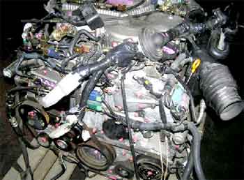
фото 1
Основные коды ошибок данных двигателей:
| Код ошибки | Описание кода неисправности |
| 0000 | неисправностей нет |
| 0100 |
MAF — датчик массового расхода воздуха |
| 0110 |
IAT sensor — датчик температуры воздуха на впуске |
| 0115 | THW sensor — датчик температуры охлаждающей жидкости |
| 0120 | THROTTLE SENSOR — электронная дроссельная заслонка и ее цепи |
| 0121 | ACCEL sensor (APPS) — датчик положения педали акселератора |
| 0130 | O2 sensor right bank (лямбда зонд) |
| 0150 | O2 sensor left bank (лямбда зонд) |
| 0180 | датчик температуры топлива (в баке) |
| 0190 | fuel pressure — датчик высокого давления (в магистрали форсунок) |
| 0325 | датчик детонации и его цепи |
| 0335 | POS sensor — датчик КВ |
| 0340 | PHASE sensor — датчик фазы распердвала |
| 0403 | EGR valve — клапан перепуска отработавших газов |
| 0500 | VSS — speed sensor — датчик скорости автомобиля |
| 0510 | idle swith — контактная группа холостого хода |
| 0600 | ENGINE-AT system — нет связи с AT (АКПП) |
| 0605 | ECCS C/U — неисправость ECU |
| 0650 | CHECK ENGINE LAMP — неисправность цепи контрольной лампы |
| 1065 | ECCS C/U — цепи питания ECU |
| 1110 | CVTC right bank valve — клапан система изменения фаз ГРМ |
| 1111 | IVT control solenoid valve электроклапан установки фаз(эл.часть) |
| 1121 | THROTTLE (actuator system) — привод электронной дроссельной заслонки |
| 1122 | THROTTLE (feedback system) — привод заслонки — обратная связь |
| 1123 | THROTTLE (motor relay system) — электропривод заслонки |
| 1135 | CVTC left bank valve — клапан системы изменения фаз ГРМ |
| 1136 | IVT control solenoid valve электроклапан установки фаз(эл.часть) |
| 1140 | CVTC phase sensor right bank — датчик фазы IVTC |
| 1145 | CVTC phase sensor left bank — датчик фазы IVTC |
| 1212 | ENGINE-TCS/ABS — нет связи с системой TCS/ABS |
| 1216 | DUI — driver unit injector — блок усилителя форсунок |
| 1217 | overheat — перегрев |
| 1232 | high pressure regulator — регулятор высокого давления |
| 1320 | сигнал системы зажигания — первичная сторона |
| 1335 | REF sensor — датчки КВ 120 град и ВМТ |
| 1706 | neutral swith — датчик нейтрали трансмисии |
| 1805 | stop lamp sw — датчик стоп сигналов |
| 1806 | brake low pressure sensor — датчик низкого давления ваккума в системе тормозов |
Данные Data monitor c разных сканеров
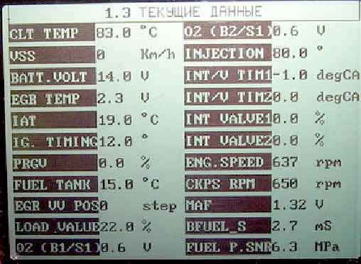
фото 2
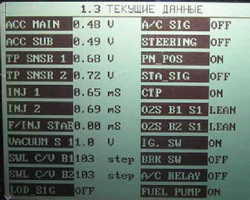
фото 3
По данным сканера можно легко наблюдать в динамике за давлением топливного насоса, расходомером воздуха, датчиками кислорода, оборотами двигателя и другими датчиками. Для анализа доступно более 45 параметров, ознакомиться с которыми можно на следующих фото:
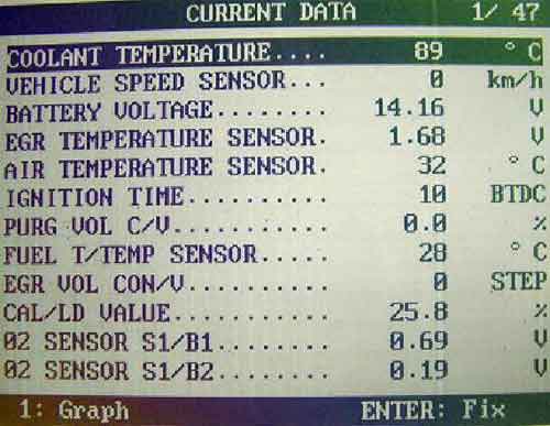
фото 4
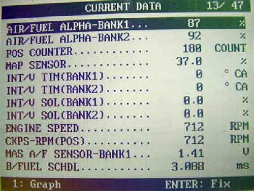
фото 5
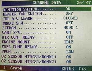
фото 6
CURRENT DATA
1.COOLANT TEMP/S [° C]
Датчик температуры охлаждающей жидкости
The engine coolant temperature (determined by the signal voltage of the engine coolant temperature sensor) is displayed.
2. Vehicle sped sensor
Датчик скорости автомобиля
The vehicle speed computed from the vehicle speed sensor signal sent from instrument cluster is displayed.
3. Battery voltage[ V ]
Напряжение в бортовой сети
The power supply voltage of ECM is displayed
4. EGR temperature sensor [V]
Датчик температуры канала EGR
The EGR temperature sensor detects temperature changes in the EGR passageway.
5. AIR temperature sensor[°C]
Датчик температуры воздуха на впуске
The intake air temperature determined by the signal voltage of the intake air temperature sensor is indicated.
6. IGN TIMING [BTDC]
Расчетный параметр угла опережения зажигания
Indicates the ignition timing computed by ECM according to the input signals. When the engine is stopped, a certain value is indicated.
7. PURG VOL C/V [%]
Индикатор работы электроклапана фильтра EVAP
Indicates the EVAP canister purge volume control solenoid valve control value computed by the ECM according to the input signals.
8. FUEL T / TMP SE [° C ]
Датчик температуры топлива
The fuel temperature judged from the fuel tank temperature sensor signal voltage is displayed.
9. EGR Vol CV [step]
Положение штока мотора EGR
The EGR volume control valve users a step motor to control the flow rate of EGR from exhaust manifold.
10. CAL/LD VALUE [%]
Расчетная нагрузка
«Calculated load value» indicates the value of the current airflow divided by peak airflow.
11. O2 Sensor S1/B1; HO2S1 (B1) [V]
Показание датчика кислорода в вольтах
The signal voltage of HO2S1 is displayed.
12. O2 Sensor S1/B2; HO2S2 (B1) [V]
Показание датчика кислорода в вольтах
The signal voltage of HO2S2 is displayed.
13 Air/Fuel ALPHA-Bank1 [%]
Соотношение топливо — воздушной смеси
The mean value of the air-fuel ratio feedback correction factor per cycle is indicated. When the engine is stopped, a certain value is indicated. This data also includes the data for the air-fuel ratio learning control.
14 Air/Fuel ALPHA-Bank2 [%]
Соотношение топливо — воздушной смеси
The mean value of the air-fuel ratio feedback correction factor per cycle is indicated. When the engine is stopped, a certain value is indicated. This data also includes the data for the air-fuel ratio learning control.
15. POS Counter [%]
Контур датчика положения коленчатого вала
16. MAP Sensor
Датчик разряжения (абсолютного давления)
the signal voltage of the absolute pressure sensor is displayed.
17. INT/V TIM (Bank1) [°CA]
Мониторинг угла опережения впускного распредвала
Indicates [°CA] of intake camshaft advanced angle.
18. INT/V TIM (Bank2) [°CA]
Мониторинг угла опережения впускного распредвала
Indicates [°CA] of intake camshaft advanced angle.
19. INT / V SOL (Bank 1) [%]- Управляющий клапан гидромуфты впускного распредвала(Bank 1). The control condition of intake valve timing control solenoid valve (determined by ECM according to input signals) is indicated. ON — intake valve timing control is operating. OFF — intake valve timing control is not operating.
20. INT / V SOL (Bank 2) [%] -Управляющий клапан гидромуфты впускного распредвала(Bank 2). The control condition of intake valve timing control solenoid valve (determined by ECM according to input signals) is indicated. ON — intake valve timing control is operating. OFF — intake valve timing control is not operating.
21. ENG SPEED [rpm]- Скорость двигателя Indicates the engine speed computed from crankshaft position sensor (POS) and camshaft position sensor (PHASE) signal.
22. CKPS — RPM (POS)-Скорость датчика положения коленчатого вала
23. MAS A / F SE — B 1 [ V ]-Показание датчика весового расхода воздуха. The signal voltage of the mass air flow sensor is displayed.
24. B / FUEL SCHDL [ msec ]-Указывает табличную расчетную ширину импульса открытия инжектора. … Indicates «Base fuel schedule» indicates the fuel injection pulse width programmed into ECM, prior to any learned on board correction.
25. ACCEL SEN 1 [V] Напряжение сигнала датчика положения педали акселератора Accelerator pedal position sensor signal voltage is displayed.
26. ACCEL SEN 2 [V]. Напряжение сигнала датчика положения педали акселератора Accelerator pedal position sensor signal voltage is displayed
27. THRTL SEN 1 [V] — Напряжение сигнала датчика положения дроссельной заслонки Throttle position sensor signal voltage is displayed
28. THRTL SEN 2 [V] — Напряжение сигнала датчика положения дроссельной заслонки Throttle position sensor signal voltage is displayed.
29. INJECT PULSE — BANK 1— Указывает фактическую ширину импульса открытия инжектора в первом «банке» … Indicates the actual fuel injection pulse width compensated by ECM according to the input signals.
30. INJECT PULSE — BANK 2. Указывает фактическую ширину импульса открытия инжектора во втором «банке». … Indicates the actual fuel injection pulse width compensated by ECM according to the input signals
31. FUEL Pressure Sensor [ MPa ] Показание датчика давления топлива
32. SWL C / V (Bank 1) Клапан заслонок
33. SWL C / V (Bank 2) Клапан заслонок
34. LOAD SIGNAL [ON/OFF] — Показание включения электрической нагрузки …Indicates [ON/OFF] condition from the electrical load signal and/or lighting switch.
35. AIR COND SIG [ON/OFF]- Сигнал включения кондиционера .Indicates [ON/OFF] condition of the air conditioner switch as determined by the air conditioner signal.
36. Power Steering Signal — Параметр включения гидроусилителя руля …PW/ST SIGNAL [ON/OFF] [ON/OFF] condition of the power steering oil pressure switch determined by the power steering oil pressure signal is indicated.
37. P/N Position Switch — Положение переключателя парковки нейтрали …P/N POSI SW [ON/OFF] Indicates [ON/OFF] condition from the park/neutral position (PNP) switch signal.
38. START SIGNAL [ON/OFF] — Сигнал стартера Indicates [ON/OFF] condition from the starter signal. After starting the engine, [OFF] is displayed regardless of the starter signal.
39. Closed Throttle POS. [ON/OFF]- Индикатор холостого хода (закрытый дроссель) Indicates idle position [ON/OFF] computed by ECM according to the throttle position sensor signal.
40 O2 Sensor Monitor S1/B1 (HO2S1 MNTR (B1) [RICH/LEAN]) Мониторинг богатой бедной смеси. Display of HO2S1 signal during air-fuel ratio feedback control: RICH — means the mixture became «rich», and control is being affected toward a leaner mixture. LEAN — means the mixture became «lean», and control is being affected toward a rich mixture.
41. O2 Sensor Monitor S1/B2HO2S1 MNTR (B2) [RICH/LEAN] Мониторинг богатой бедной смеси Display of HO2S1 signal during air-fuel ratio feedback control: RICH — means the mixture became «rich», and control is being affected toward a leaner mixture. LEAN — means the mixture became «lean», and control is being affected toward a rich mixture.
42. IGNITION SWITCH [ON/OFF] — Индикатор работы выключателя зажигания …Indicates [ON/OFF] condition from ignition switch.
43 Heater Fan SWITCH — Вентилятор охлаждения .
44 IDL A/V Learn. Display the condition of idle air volume learning. YET — Idle air volume learning has not been performed yet. CMPLT — Idle air volume learning has already been performed successfully. INCMP — Idle air volume learning has not been performed successfully.
45 BRAKE SW [ ON / OFF ] Индикатор включения педали тормоза. Indicates [ON/OFF] condition from ASCD brake switch signal, and ASCD clutch switch signal (M/T models) or park/neutral position relay signal (A/T models).
46. AIR COND RLY [ON/OFF] Индикатор включении кондиционера The air conditioner relay control condition (determined by ECM according to the input signal) is indicated
47. ENGINE MOUNT [IDLE/TRVL]- Контроль крепления двигателя The control condition of the electronic controlled engine mount (computed by ECM according to input signals) is indicated. IDLE — Idle condition; TRVL — Driving condition.
48. FUEL PUMP RLY [ON/OFF] Индикатор состояния реле топливного насоса Indicates the fuel pump relay control condition determined by ECM according to the input signals.
49. O2 Sensor HTR(S1/Bank1) HO2S1 HTR (B1) [ON/OFF] — Индикация состояния нагревателя датчика кислорода , вкл / выкл Indicates [ON/OFF] condition of heated oxygen sensor 1 heater (front) determined by ECM according to the input signals.
50. O2 Sensor HTR(S1/Bank2) HO2S1 HTR (B2) [ON/OFF] — Индикация состояния нагревателя датчика кислорода , вкл / выкл Indicates [ON/OFF] condition of heated oxygen sensor 1 heater (front) determined by ECM according to the input signals.
51. FUEL PUMP CONTROL MODULE (FPCM) [high/low] — Режим управления топливным насосом — высокий , низкий . (принимает значения high – low) это система контроля напряжения на насосе подкачки в баке в зависимости от оборотов мотора (подает частичное или полное напряжение на топливный насос)
52. VARI S / V— система изменения длины впускного коллектора variable switch / valve
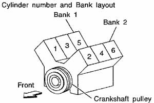
Ориентация «Bank 12» на двигателе.
«Болезни»:
За несколько лет работы с данными двигателями выработался определенный опыт.
Вот основные уязвимые места в двигателе:
1. Неисправность датчика MAF, в простонародье – «расходомера воздуха»
2. Потеря давления в топливном насосе
3. Неисправность катушек зажигания
4. Плохой запуск или его отсутствие из-за неисправности стартера
5. Потеря мощности из-за «срыва» катализаторов (фото 30 — 33)
6. Постоянная детонация и повышенный расход топлива из-за большого количества сажи на клапанах (засаженность)
7. Нарушение фазы газораспределения
8. Неправильная работа инжекторов
Наверное, самая распространенная жалоба клиентов при посещении сервиса – горящий CHECK ENGINE

и, иногда, временное, а иногда постоянное «троение» двигателя. Как следствие — потеря мощности; как правило, это связано с нарушениями в системе зажигания. Блок управления оценивает работу катушек зажигания и при малейшем нарушении информирует водителя о проблеме (зажиганием лампы CHECK ENGINE).
При сканировании выявляется код Р1320 — сигнал системы зажигания, «первичная сторона».
Про эту проблему уже писали на страницах данного форума.
Хочу лишь добавить свою методику проверки неисправной катушки зажигания. На левой головке двигателя доступ к катушкам зажигания открыт и здесь совсем не составляет труда осциллографом проверить импульсы на управляющих выводах катушек. На правой же головке доступ, напротив, затруднен. Для нормальной проверки катушки приходится демонтировать. Я меняю их местами с разных «головок» для проверки. Делаю это для того, что бы визуально проверить состояние наконечников. Нередки случаи пробоев и «зеленения» контактов из-за воды или масла.
Важно проверить катушку на разряднике — на неисправной катушке будут видны явные пропуски искрообразования.
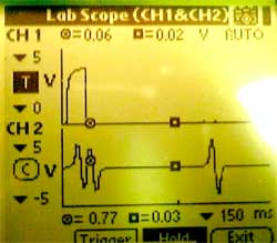
Вот несколько осциллограмм:
ФОТО 7 — правильная работа
ФОТО 8 — катушка в «обрыве» (силовой транзистор или обмотка)
ФОТО 9 и 10 — неправильная работа силового транзистора в катушке.
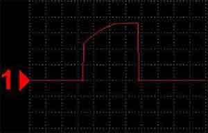
фото 7
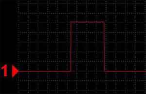
фото 8
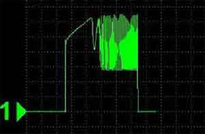
Фото 9
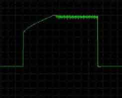
Фото 10
При проверке нужно обращать внимание и на наличие масла в свечных колодцах (оно туда может попадать через «задубевший» сальник клапанной крышки). При наличии масла есть вероятность «пробоя» катушки либо коммутатора в ней.
Следующая проблема связана с отказом или нарушением правильной работы датчика MAF — датчик массового расхода воздуха.
При работе двигатель потребляет огромное количество воздуха и качество его фильтрования влияет коренным образом на работу данного датчика. В расходомере производители применили открытый кристалл. При постоянном воздействии частиц пыли на кристалл он мутнеет (от постоянного «пескоструя») или просто забивается грязью и, как результат, параметры датчика «уходят в сторону». Нормальная работа двигателя становится невозможной. Диагностика данного девайса очень проста – замеряем напряжение при включенном зажигании на сигнальном выводе датчика и сравниваем с нормативными показателями (1,03- 1,05 вольта).
Показания завышены:
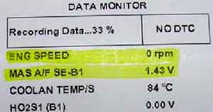
фото 11
Завышенные показания при работе двигателя на хх
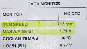
фото 12
При отклонениях в параметрах меняем датчик на исправный.
Правильные показания:
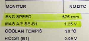
фото 13
При покупке (заказе) датчика следует учитывать цвет метки на расходомере и на его корпусе.
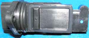
фото 14
При полном обрыве датчика блок управления фиксирует код ошибки P 0100 MAF (Mass Air Flow) Sensor.
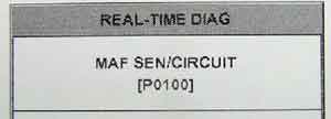
фото 15
При неисправном датчике (внутренний обрыв) на сканере «застынет» показание в 1,01-1,04вольт, и оно не будет меняться при перегазовках. При обрыве проводки к датчику
— показания на мониторе сканера будут нулевыми.
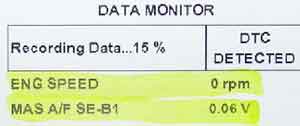
фото 16
Внутренний обрыв или « неудачная помывка датчика»
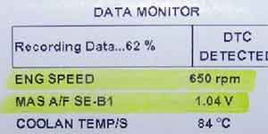
фото 17
В Интернете бытует мнение о возможности промывания в спирте загрязнённой части датчика. Мне несколько раз приходилось мыть датчик, но к положительному результату эта процедура не приводила.
Если же параметры датчика заметно «уплыли» (на хх 1,5 — 1,7 в), то временно восстановить работу двигателя можно изменив количество проходящего через него воздуха. Для этого нужно лишь на 10 — 15 градусов повернуть датчик по часовой стрелке. Болты крепления, конечно, нужно демонтировать.
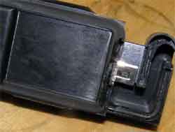
фото 18
Более серьезная проблема – это износ ТНВД. При пониженном давлении двигатель способен работать, но наблюдается заметный черный выхлоп, «троение», потеря мощности и очень большой расход топлива. Регистрировать давление очень просто. На сканер выводится строчка с параметром с датчика давления, установленного на насосе. Давление изменяется соразмерно оборотам двигателя.
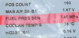
фото 19
Правильное давление — 6,8-7,4МРа на хх.
Если нет сканера, то можно проконтролировать давление с помощью вольтметра на разъёме датчика давления. Разъем датчика расположен в доступном месте и проделать эту процедуру не составит труда.
можно посмотреть зависимость напряжения от давления.
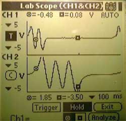
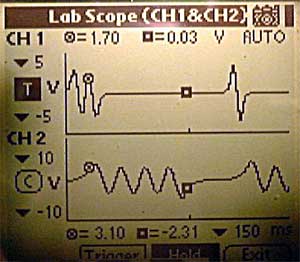
Форма импульса на клапане регуляторе давления:
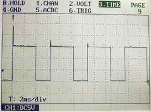
фото 20
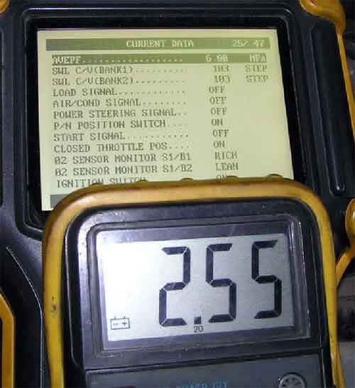
Фото 21
(Р1232) high pressure regulator — регулятор высокого давления
то Вам, как диагносту, следует сделать некоторые замеры. Вы должны проверить наличие управляющего импульса на клапане ТНВД и проверить, какое давление развивает подкачивающий насос в топливном баке.
Это необходимо делать, чтобы исключить неправильный диагноз по замене насоса и не стать впоследствии «счастливым его обладателем». Не исключается вероятность того, что при заклинивании насоса «срезало» привод ТНВД и «просто замена» не решит проблему, а время будет потеряно для Вас и для Клиента.
Часто при разборе насосов видны следы износа плунжеров, подшипников, разрыва гофры, заклинивание плунжеров. Основными виновниками выхода из строя насоса являются вода, грязь, песок, которых предостаточно в нашем «чистом» отечественном топливе.
Показания сканера — низкое давление
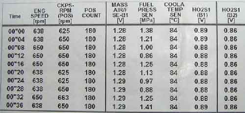
фото 22
Неисправные плунжеры
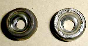
Фото 23
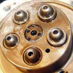
Фото 24
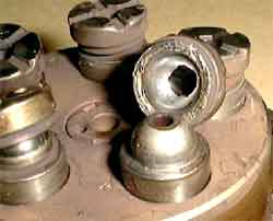
Фото 25
Проверяйте после снятия ТНВД состояние привода,-
Привод «срезан»:
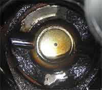
Фото 26
Исправный привод
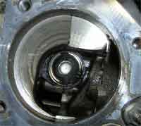
фото 27
А здесь «разбитый» подшипник в насосе деформировал «гофру» из-за деформированного сальника на приводе (вытекло масло из насоса и произошёл перегрев подшипника)
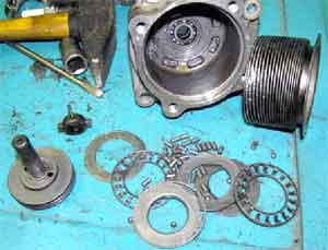
фото 28
При снятии ТНВД обращайте внимание на направляющие втулки — их две. Они легко могут скатиться в полость головки, что приведет к непредсказуемым последствиям.
Следует отметить, что в новом насосе нужно обязательно проверить наличие масла, без которого насос не проработает и несколько часов.
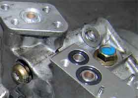
фото 29
Многие проблемы на данных двигателях пересекаются. Одна является следствием другой. При проблемах в системе зажигания и отказах в работе катушек, несгоревший бензин догорает в катализаторах. Температура катализатора увеличивается до немыслимых значений. Коллектор накаляется докрасна, появляется вероятность возгорания автомобиля. На «Цедриках» и «Глориях» установлены три катализатора. Два непосредственно рядом с головками (они металлические) и один керамический под днищем автомобиля.
Катализаторы нередко срывает со штатного места и ими, буквально, выпускной тракт «запаковывается» как пробкой. Теряется мощность двигателя.
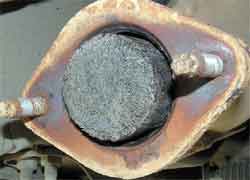
Фото 30
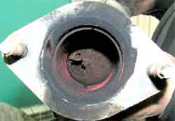
фото 31
Проконтролировать «забитость» можно при помощи датчика давления. Доступ к датчикам кислорода ограничен. Порт датчика давления подключается в отверстия лямбда-зондов. При диагностике «пытайте» Клиента — сколько времени он катается на «троящем» двигателе.
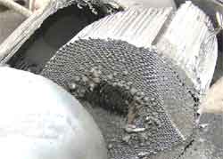
фото 32
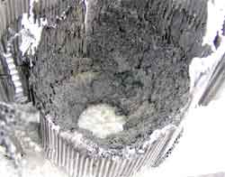
фото 33
При работе на ХХ следует обращать внимание на температуру патрубков системы EGR. Были случаи, когда металлические частицы прогоревшего катализатора попадали под шток клапана, тем самым не давая ему закрыться.
Как результат — неровная работа двигателя и раскаленная подводная трубка.
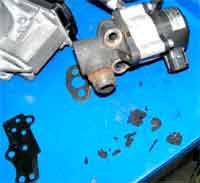
фото 34
Еще одна серьезная проблема — это так называемая «засаженность» двигателя. Коллектор двигателя с прямым впрыском — он большого обьема. По моему мнению, это обусловлено необходимостью улавливания частиц сажи, оставшихся после полного сгорания смеси. Сажи накапливается огромное количество. В практике встречались автомобили с практически полностью перекрытыми клапанными каналами. Чистку коллектора следует производить при возникновении постоянной детонации при работе двигателя. Увидеть сажу можно просто при осмотре форсунки холодного пуска.
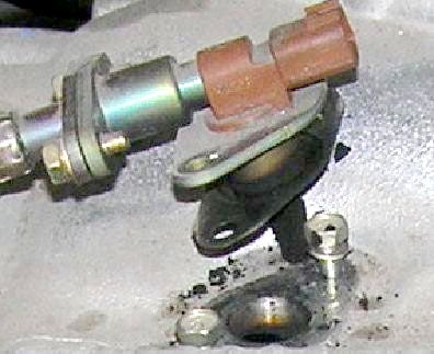
фото 35
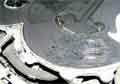
Фото 36
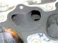
Фото 37
фото 38
Очистка, как правило, не занимает много времени, так как кокс и сажа практически всегда имеют «сухую» структуру. Весь этот налет легко снимается скребками и всевозможными ёршиками. С чисткой коллектора не возникнет трудностей, а вот с клапанами придется повозиться. Ставим поршень цилиндра в ВМТ и счищаем сажу на днище клапана. Затем удаляем сажу пылесосом. Так все 12 отверстий.
Почищенный клапан
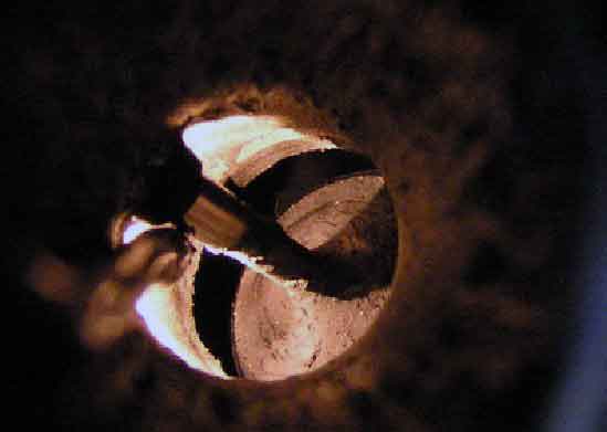
фото 39
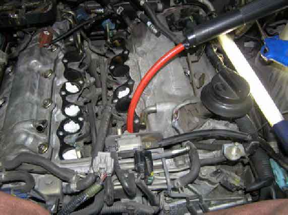
фото 40
Остатки выдуваем сжатым воздухом. Если вам «не повезло» и колпачки «текут», то кокс будет сырой — здесь придется воспользоваться очистителями. А собирать растворённую грязь либо шприцем, либо «отсосом».
Результат очистки коллектора и клапанов
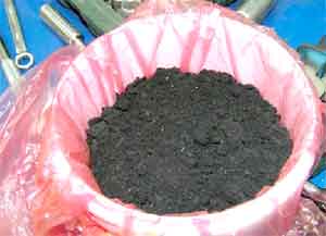
Фото 41

фото 42
Часто привозят автомобили с проблемами невозможности запуска. Блок управления регистрирует нарушение в работе датчика коленвала. Код P0335POS sensor — датчик КВ
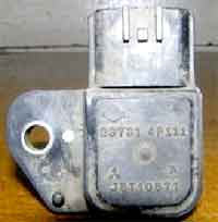
Фото 43
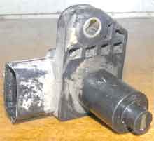
фото 44
Блок управления постоянно фиксирует код ошибки.
Замена датчика не решает проблемы.
Импульс имеется, а запуска не происходит.
Проблема лежит глубже.
Этот «трабл» не раз обсуждался на нашем форуме, я просто повторю то, что уже писалось и добавлю из своего опыта.
Вся проблема заключается в «неровной работе стартера», «просадке» напряжения, разбитые втулки или изогнутый маховик, налипание частиц металла к датчику. Это приводит к тому, что начальный импульс датчика коленвала становится неправильным.
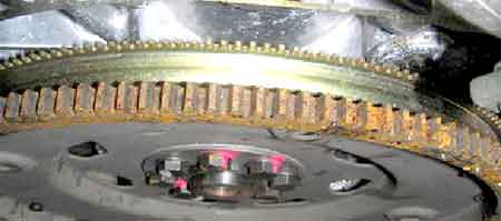
фото 45
(…на нашем форуме диагност из города Санкт-Петергбурга Vasaby так писал про эту проблему:
«Прикол в том, что электрические помехи от стартера тут ни при чем. Минусовой провод батарея-мотор можно поставить удлиненный, проложить мимо датчика и увести на болт крепления стартером. И все равно запуск станет легче. Дело в чувствительности датчика скорости вращения колена к большим угловым ускорениям-замедлениям венца при подклинивании якоря стартера или рывкам колена вблизи ВМТ из-за недостаточной мощности стартера».
Проблема решается либо заменой стартера, либо переносом дополнительного минусового провода на болт крепления стартера…).
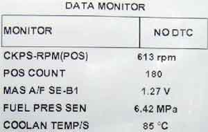
фото 46
Регистрировать данную проблему можно, наблюдая за параметром POS COUNT в «дате» сканера его значение должно быть 180
http://forum.autodata.ru/1/3904/
Можно просматривать импульс с датчика коленвала.
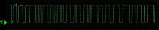
фото 47
Проблема просмотра импульса в доступе к датчику. Импульс можно снять непосредственно на датчике либо на блоке управления.
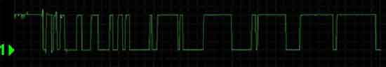
фото 48
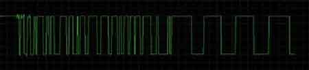
фото 49
Чем меньше участок с «грязным» импульсом, тем быстрее произойдет запуск.
Есть еще одна проблема с затруднённым запуском – DTC P1335.
REF sensor – датчк КВ 120 град и ВМТ
Отсутствие сигнала с датчика коленвала (переднего) также нарушает процесс синхронизации. При отсутствии этого сигнала двигатель все же запускается, но с трудом (долгое вращение стартера)
Правильный сигнал
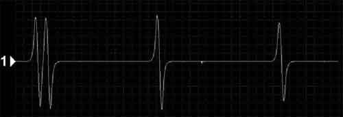
фото 50
И сам датчик
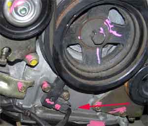
фото 51
Одна интересная деталь — ВМТ это всегда REF двойной импульс, PHASE 3 импульса — 1 цилиндр, 4 импульса — 4 цилиндр.
Так можно проверить метки цепи не снимая крышки на двухканальном осциллографе. Так как датчики индуктивные, то можно вообще зажигание не включать (со снятыми коллекторами) просто подав «+» на стартер.
Синхронизация_ REF двойной импульс и PHASE 4 импульса — 4 цилиндр.
Синхронизация ВМТ и катушки 1 цилиндра
IGN — это положение импульса на катушку 1 го цилиндра и REF
На данных двигателях установлены низкоомные инжекторы, способные работать на обычном и на очень большом давлении, до 120кгсм2. Управляющий импульс вырабатывается специальным блоком — усилителем инжекторов. Усилитель вырабатывает импульс амплитудой до 100 вольт, который способен открыть и закрыть инжектор под большим давлением. За время эксплуатации сопла инжекторов загрязняются, загрязняется и игла.
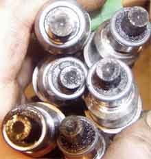
Фото 52
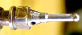
фото 53
Тем самым нарушается нормальная работа форсунок, распыл и производительность.
Мыть форсунки следует в ультразвуке по аналогии с инжекторами от TOYOTA или MMC.
Подающая топливо «рейка» прикручивается к инжекторам специальными болтами. Для их демонтажа потребуется изготовить особый ключ.
Снимать форсунки следует с осторожностью, и использовать простейший съемник.
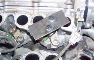
Фото 54
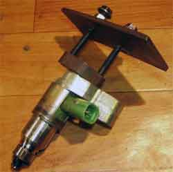
фото 55
Демонтаж форсунки надо производить плавно и равномерно во избежание ее повреждения. Предварительно на посадочное место надо распылить смазку, например VD-40.
«Закоксованные» форсунки также приводят к обеднению смеси, потери мощности, проявлениям детонации, не устойчивому ХХ.
Бывали случаи, когда из-за грязи форсунка начинает «лить» топливо. Увеличивается общий расход топлива. Заметен запах и «черный» выхлоп. Свеча зажигания не успевает очищаться, а датчик кислорода постоянно регистрирует «богатую» смесь. Такую форсунку редко удается «оживить».
Работу инжекторов можно наблюдать осциллографом прямо на усилителе инжекторов.
Осциллограмма с вывода усилителя относительно массы двигателя
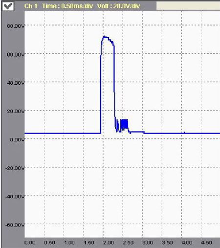
фото 56
При изменении в сопротивлении обмотки инжектора фиксируется код неисправности P1216 injector D/U., эта ошибка может указывать и на отказ усилителя.
Следующая проблема связана с нарушением фаз газораспределения.
Блок управления двигателем фиксирует шесть кодов, связанных с данной проблемой. На распредвале установлена шестерня, способная изменять его положение в зависимости от давления подводимого к ней масла. В этой системе есть четыре ключевых элемента – клапан, муфта с шестерней, датчик положения муфты, датчик распредвала
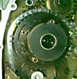
фото 57
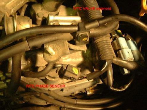
фото 58
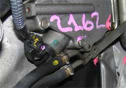
фото 59
Датчик фазы и распредвала
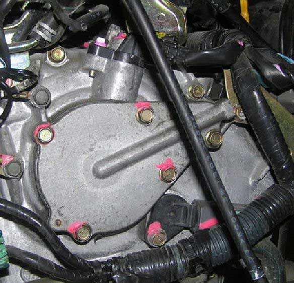
фото 60
При нарушении в работе клапана (клапанов) блок управления фиксирует ошибку
DTC P1111, P1136 IVT control solenoid valve.
Эти коды указывают на электрические проблемы в управляющих клапанах (следует проверить сопротивление, наличие управляющего сигнала, питание). Сопротивление клапана 7,0 -7,7ом при температуре 20 градусов Цельсия.
При отсутствии импульса с датчиков положения муфты, ECM регистрирует ошибки
DTC P1140, P1145 IVT control position sensor.
Следует проверить импульсы на датчиках и наличие питания. Если смотреть на двигатель, то код P1140 указывает на неисправный левый датчик, а код P1145 на правый.
Правильный импульс
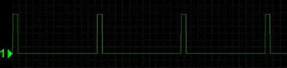
фото 61
При невозможности установки заданного положения распредвала и при наличии импульсов с датчиков фазы фиксируются коды
DTC P 1110, P1135. INTAKE VALVE TIMING CONTROL PERFORMANCE
При возникновении этих кодов следует проверить гидравлическую часть системы, подклинивание клапана, грязь в сетке, неисправность самой гидравлической муфты.
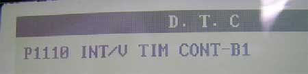
фото 62
Форму сигналов можно посмотреть по ссылке
Форма сигнала с датчика распредвала:
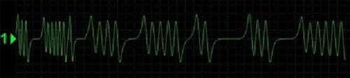
фото 63
И напоследок небольшая хитрость по снятию и установке необычных разъемов на датчиках.
Под пружинки механизма попадает грязь, из-за чего разъеденить разъем очень сложно. Чтобы не сломать эту конструкцию, нужно брызнуть проникающей смазкой в место хода защелки и вся конструкция вновь заработает.
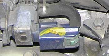
фото 64
Я попытался максимально коротко осветить наиболее часто встречающиеся проблемы с данной серией двигателей. Всем удачных ремонтов и добрых клиентов.
Владимир Бекренёв при поддержке Антона Воробьёва и Арида Гаджиева
© Легион-Автодата
Skip to content
How to clear forklift error codes
How to clear forklift error codes?
In all new generation of forklift and also some old models of forklift sometimes when you are using the forklift will see some error code on the monitor(dashboard) of the forklift.
In different forklift, each Error code means different things.
On Yale and Hyster forklift the error code can be showed or can be in the system.
Yale and Hyster Forklift Fault Codes List

for going inside the system you need the password that the company using or can be changed by the dealer before they ship it to the customer.
When you go inside the system you are able to see the error code and you will see how many time this error code showed in your forklift and also when (In witch hours of using the forklift), from the error code list that the company gives for each forklift to the dealers and forklift technician you will understand what is the problem and you can solve the issue with any headache.
In some other trucks same as Raymond, Toyota, and Nissan you will see the error code directly in the forklift and you can solve the issue and use the forklift easy.
How to detect and figure out forklift error codes?
In all forklift when the technician connect with computer to forklift all the issue and error will show up and he can fix for you, your forklift
Sometimes you see the error code in your forklift but you see your forklift work well, But it can be a point and you have to solve it because it is same as alarm and if you don’t ask the forklift technician for this issue in future you will be stuck with the bigger problem and big charge to repair your forklift.
Our suggestion is when you do your daily checklist please look and see your forklift doesn’t have any error code.
If you find any error code, don’t use the forklift to solve the issue.
How you can figure out forklift error codes?
Please leave the error code below this article then We and other specialists will answer you as soon as possible.
Our technician at Forklift Plus can detect and figure out your forklift problems as soon as possible.
Share This Story, Choose Your Platform!
Related Posts
Page load link
Go to Top
NISSAN Forklift Truck Fault Codes list
E03 VCM communication error
E04 ECM communication error
E05 DCM communication error
E06 HST communication error
E07 MP communication error
E08 TMS communication error
E21 Air flow meter error signal
E22 Water temperature sensor error signal
E23 Throttle sensor error signal
E24 Accelerator sensor error signal
E25 O2 sensor error signal
E26 O2 sensor heater error signal
E27 POS sensor error signal
E28 PHASE sensor error signal
E29 Self shutdown system diagnostic result error signal
E30 ECCS C/U error signal
E31 Electronic control throttle control error signal
E32 Overhear signal (STEP 1)
E33 Overheat signal (STEP 2)
E34 Spark system error signal
E35 LPG F/INJ disconnection diagnostic result signal
E36 LPG fuel pressure sensor diagnostic result signal
E38 LPG vaporizer diagnostic result signal
E39 Mast-high SW diagnostic result signal
E40 Oil pressure sensor diagnostic result signal
E41 Stop lamp SW error signal
F02 Battery voltage error
F57 Tilt backward solenoid error
F03 VCM communication error
F59 Tilt solenoid leak
F04 ECM communication error
F60 Attack-1A solenoid error
F05 DCM communication error
F62 Attach-1B solenoid error
F06 HST communication error
F64 Attach-1 solenoid leak
F07 MP communication error
F65 Attach-2A solenoid error
F08 TMS communication error
F67 Attach-2B solenoid error
F10 Lift lever neutral error
F69 Attach-2 solenoid leak
F11 Tilt lever neutral error
F70 Attach-3A solenoid error
F12 Attach-1 lever neutral error
F72 Attach-3B solenoid error
F13 Attach-2 lever neutral error
F74 Attach-3 solenoid leak
F14 Attach-3 lever neutral error
F75 Unload solenoid error
F16 Shift lever error
F77 Lift lock solenoid error
F17 Speed error
F7 Unload solenoid leak
E29 Self shutdown system diagnostic result error signal
F20 Lift lever error
F80 Knob position solenoid error
F22 Tilt lever error
F82 Tilt lock solenoid error
F24 Attach-1 lever error
F24 Knob position solenoid leak
F26 Attach-2 lever error
F85 T/M forward solenoid error
F28 Attach-3 lever error
F87 T/M backward solenoid error
F30 Main oil pressure sensor error
F89 T/M solenoid leak
F32 Lift oil pressure sensor error
F34 Speed sensor error
F36 Tire angle sensor error
F38 Tilt angle sensor error
F40 Steering error
F50 Lift up solenoid error
F52 Lift down solenoid error
F54 Lift solenoid leak
F01 Memory check error
F55 Tilt forward solenoid error
P03 VCM communication error
P04 ECM communication error
P05 DCM communication error
P06 HST communication error
P07 MP communication error
P08 TMS communication error
P22 Shift lever error signal

Самодиагностика Nissan Cedric & Nissan Gloria Y34. Считывание результатов: Поверните ключ зажигания в положение «ON», не запускайте двигатель; Замкните контакты («IGN» и «CHK») контакты 1 и 8 не менее чем на 2 сек.; уберите перемычку Некоторые пояснения по методике чтения кодов самодиагностики: «0» индицируется 10-ю вспышками; 4-ый разряд кода индицируется длинными вспышками длительностью 0.6 сек.; 3-ий разряд и ниже индицируется короткими вспышками длительностью 0.3 сек.; Промежутки между цифрами в коде (он 4-х значный) равны 1 сек.; Промежутки между кодами равны 1.8 сек.; Код «0000» означает — «неисправности не обнаружены».
Код ошибки
Описание кода неисправности
0000
неисправностей нет
0100
MAF — датчик массового расхода воздуха
0110
IAT sensor — датчик температуры воздуха на впуске
0115
THW sensor — датчик температуры охлаждающей жидкости
0120
THROTTLE SENSOR — электронная дроссельная заслонка и ее цепи
0121
ACCEL sensor ( APPS ) — датчик положения педали акселератора
0130
O2 sensor right bank ( лямбда зонд )
0150
O2 sensor left bank ( лямбда зонд )
0180
датчик температуры топлива ( в баке )
0190
fuel pressure — датчик высокого давления ( в магистрали форсунок )
0325
датчик детонации и его цепи
0335
POS sensor — датчик КВ
0340
PHASE sensor — датчик фазы распердвала
0403
EGR valve — клапан перепуска отработавших газов
0500
VSS — speed sensor — датчик скорости автомобиля
0510
idle swith — контактная группа холостого хода
0600
ENGINE-AT system — нет связи с AT ( АКПП )
0605
ECCS C/U — неисправость ECU
0650
CHECK ENGINE LAMP — неисправность цепи контрольной лампы
1065
ECCS C/U — цепи питания ECU
1110
CVTC right bank valve — клапан система изменения фаз ГРМ
1111
IVT control solenoid valve электроклапан установки фаз(эл.часть)
1121
THROTTLE ( actuator system ) — привод электронной
дроссельной заслонки
1122
THROTTLE (feedback system ) — привод заслонки — обратная связь
1123
THROTTLE ( motor relay system ) — электропривод заслонки
1135
CVTC left bank valve — клапан системы изменения фаз ГРМ
1136
IVT control solenoid valve электроклапан установки фаз(эл.часть)
1140
CVTC phase sensor right bank — датчик фазы IVTC
1145
CVTC phase sensor left bank — датчик фазы IVTC
1212
ENGINE-TCS/ABS — нет связи с системой TCS/ABS
1216
DUI — driver unit injector — блок усилителя форсунок
1217
overheat — перегрев
1232
high pressure regulator — регулятор высокого давления
1320
сигнал системы зажигания — первичная сторона
1335
REF sensor — датчки КВ 120 град и ВМТ
1706
neutral swith — датчик нейтрали трансмисии
1805
stop lamp sw — датчик стоп сигналов
1806
brake low pressure sensor — датчик низкого давления ваккума в
системе тормозов
Войдите или зарегистрируйтесь, чтобы писать комментарии, задавать вопросы и участвовать в обсуждении.
![]()
MAN truck Fault Codes DTC
MAN truck Fault Codes DTC
MAN truck Fault Codes DTC.pdf
Adobe Acrobat Document
473.2 KB
MAN Truck Fault Codes DTC — EBS 5 Knorr
Code (SPN) Description Reason, verification and system response.
597 Module foot brake switch 1. Short to Ground (FMI5). STOP warning light is amber. User functions are not limited. Electrical or mechanical failure of a foot brake module,
faulty wiring or contacts in the connectors. Check wiring and connections between the EBS unit (A402) and the sensor module foot brake (V337) for insulation and continuity. Disconnect from the
EBS unit (A402) and inspect the resistance between the contacts of a foot brake module _SIG1 (X1 / 5) and _GND (X1 / 4). R_SW1 open: R_SIG1 resistance value is less than 4.8 ohms or more 6.5
ohms. R_SW1 closed: resistance value R_SIG1 5.4-6.2
ohms. If the resistance values are outside of acceptable values, replace the module foot brake.
597 Module foot brake, switch on the power supply 1. Short Ubat (FMI6). STOP warning light is amber. User functions are not limited. Electrical or mechanical failure of a foot
brake module, faulty wiring or contacts in the connectors. Check wiring and connections between the EBS unit (A402) and the sensor module foot brake (V337) for insulation and continuity.
Disconnect from the EBS unit (A402) and inspect the resistance between the contacts of a foot brake module _SIG1 (X1 / 5) and _GND (X1 / 4). R_SW1 open: R_SIG1 resistance value is less than 4.8
ohms or more 6.5 ohms. R_SW1 closed: resistance value R_SIG1 5.4-6.2 ohms. If the resistance values are outside of acceptable values, replace the module foot brake.
603 Module foot brake switch 2. Short to Ground (FMI5). STOP warning light is amber. User functions are not limited. Electrical or mechanical failure of a foot brake module,
faulty wiring or contacts in the connectors. Check the wiring of a foot brake module. If the wiring is OK, replace the module foot brake.
603 Module foot brake switch 2. Short to power supply Ubat (FMI6). STOP warning light is amber. User functions are not limited. Electrical or mechanical failure of a foot brake
module, faulty wiring or contacts in the connectors. Check the wiring of a foot brake module. If the wiring is OK, replace the module foot brake.
609 The central control unit in the controller. Undefined fault (FMI0). STOP warning light lit in red, and red lights lamp total control of brakes. All user functions are
disabled. Interrupted software download, damaged EBS microcontroller unit (A402). Update the software in EBS unit (A402), clear the fault memory. If the fault code appears again, replace the EBS
unit (A402).
627 Power Supply. Not identified (FMI3). STOP warning light lit in red, and red lights lamp total control of brakes. All user functions are disabled. A break in the power supply
circuit or defective EBS unit (A402). Check the connection terminals 30, the power supply circuit: UB_1 (X1 / 17), UB_2 (X1 / 16), GND_1 (X1 / 12), GND_2 (X1 / 11).
The central control device, and controller. Undefined fault (FMI0). STOP warning light lit in red, and red lights lamp total control of brakes. All user functions are disabled. Temporary
fault condition. Temporarily switching to backup. For safety, the system performs a diagnostic test for the system.
639 Channel J1939 data CANtransmissii. No signal (FMI4). STOP warning light lit in red, and red lights lamp total control of brakes. All user functions are disabled. Defective
unit EBS (A402). Clear the fault memory. If the fault code appears again, replace the EBS unit (A402).
639 channel data J1939, CAN powertrain. Open (FMI10). STOP warning light is amber. Switches the retarder, control ESP, control the adjustment of reference torque (DTC),
dvigatelyaASR control, brake control ASR. Damaged wiring CAN data channel connection with the transmission, a fault in the power supply circuit or electromagnetic interference. Check wiring and
wiring data channel transmission unit for continuity and insulation. Check the correct functioning of the control units associated with CAN.
645 channel data connection with tachograph timeout. No signal (FMI4). STOP warning light is amber. User functions are not limited. Electromagnetic interference, an external
device is disconnected from the data channel, the external device sends a message, not all of a malfunction. Check wiring channel data for continuity and insulation. Check for proper operation of
the external device.
746 differential lock valve. Short to Ground (FMI5). STOP warning light is amber. differential lock function is limited. Damaged wiring in the interlock circuit or defective EBS
unit (A402). Clear the fault memory. Check wiring and connections between the EBS unit (A402) and lock the valve.
746 differential lock valve. Short to power supply Ubat (FMI6). STOP warning light lit in red, and red lights lamp total control of brakes. differential lock function is limited.
Damaged wiring in the interlock circuit or defective EBS unit (A402). Clear the fault memory. Check wiring and connections between the EBS unit (A402) and lock the valve.
789 Sensor wheel speed, wheel 1. No signal (FMI4). STOP warning light is amber. Switches the control of ABS, control ESP, control the adjustment of reference torque (DTC), the
engine control ASR, brake control ASR. The large gap between the sensor and gear, damaged wiring, contacts in the connectors, sensor is faulty, damaged or defective gear modulator. Check the
sensor resistance: 950-1930 ohms. Check wiring and contacts in the connectors between the modulator and the sensor. Check the integrity of gear. Check the clearance between the sensor and the
gear. Check wheel bearing play. If the wiring, the sensor, gear, wheel bearing is OK, replace the modulator.
789 Sensor wheel speed, wheel 1. Short (FMI7). STOP warning light is amber. Switches the control of ABS, control ESP, control the adjustment of reference torque (DTC), the engine
control ASR, brake control ASR. The closure between a wiring of different sensors or faulty modulator. Check the sensor resistance: 950-1930 ohms. Check wiring and contacts in the connectors
between the modulator and the sensor. If the wiring and the sensor is normal, replace the modulator.
790 Sensor wheel speed, wheel 2. No signal (FMI4). STOP warning light is amber. Switches the control of ABS, control ESP, control the adjustment of reference torque (DTC), the
engine control ASR, brake control ASR. The large gap between the sensor and gear, damaged wiring, contacts in the connectors, sensor is faulty, damaged or defective gear modulator. Check the
sensor resistance: 950-1930 ohms. Check wiring and contacts in the connectors between the modulator and the sensor. Check the integrity of gear. Check the clearance between the sensor and the
gear. Check wheel bearing play. If the wiring, the sensor, gear, wheel bearing is OK, replace the modulator.
790 Sensor wheel speed, wheel 2. Short (FMI7). STOP warning light is amber. Switches the control of ABS, control ESP, control the adjustment of reference torque (DTC), the engine
control ASR, brake control ASR. The closure between a wiring of different sensors or faulty modulator. Check the sensor resistance: 950-1930 ohms. Check wiring and contacts in the connectors
between the modulator and the sensor. If the wiring and the sensor is normal, replace the modulator.
791 Sensor wheel speed, wheel 3. No signal (FMI4). STOP warning light is amber. Switches the control of ABS, control ESP, control the adjustment of reference torque (DTC), the
engine control ASR, brake control ASR. The large gap between the sensor and gear, damaged wiring, contacts in the connectors, sensor is faulty, damaged or defective gear modulator. Check the
sensor resistance: 950-1930 ohms. Check wiring and contacts in the connectors between the modulator and the sensor. Check the integrity of gear. Check the clearance between the sensor and the
gear. Check wheel bearing play. If the wiring, the sensor, gear, wheel bearing is OK, replace the modulator.
791 Sensor wheel speed, wheel 3. Closing (FMI7). STOP warning light is amber. Switches the control of ABS, control ESP, control the adjustment of reference torque (DTC), the
engine control ASR, brake control ASR. The closure between a wiring of different sensors or faulty modulator. Check the sensor resistance: 950-1930 ohms. Check wiring and contacts in the
connectors between the modulator and the sensor. If the wiring and the sensor is normal, replace the modulator.
792 Sensor wheel speed, wheel 4. No signal (FMI4). STOP warning light is amber. Switches the control of ABS, control ESP, control the adjustment of reference torque (DTC), the
engine control ASR, brake control ASR. The large gap between the sensor and gear, damaged wiring, contacts in the connectors, sensor is faulty, damaged or defective gear modulator. Check the
sensor resistance: 950-1930 ohms. Check wiring and contacts in the connectors between the modulator and the sensor. Check the integrity of gear. Check the clearance between the sensor and the
gear. Check wheel bearing play. If the wiring, the sensor, gear, wheel bearing is OK, replace the modulator.
792 Sensor wheel speed, wheel 4. Closure (FMI7). STOP warning light is amber. Switches the control of ABS, control ESP, control the adjustment of reference torque (DTC), the
engine control ASR, brake control ASR. The closure between a wiring of different sensors or faulty modulator. Check the sensor resistance: 950-1930 ohms. Check wiring and contacts in the
connectors between the modulator and the sensor. If the wiring and the sensor is normal, replace the modulator.
793 Sensor wheel speed, wheel 5. No signal (FMI4). STOP warning light is amber. Switches the control of ABS, control ESP, control the adjustment of reference torque (DTC), the
engine control ASR, brake control ASR. The large gap between the sensor and gear, damaged wiring, contacts in the connectors, sensor is faulty, damaged or defective gear modulator. Check the
sensor resistance: 950-1930 ohms. Check wiring and contacts in the connectors between the modulator and the sensor. Check the integrity of gear. Check the clearance between the sensor and the
gear. Check wheel bearing play. If the wiring, the sensor, gear, wheel bearing is OK, replace the modulator.
793 Sensor wheel speed, wheel 5. Closing (FMI7). STOP warning light is amber. Switches the control of ABS, control ESP, control the adjustment of reference torque (DTC), the
engine control ASR, brake control ASR. The closure between a wiring of different sensors or faulty modulator. Check the sensor resistance: 950-1930 ohms. Check wiring and contacts in the
connectors between the modulator and the sensor. If the wiring and the sensor is normal, replace the modulator.
794 Sensor wheel speed, wheel 6. No signal (FMI4). STOP warning light is amber. Switches the control of ABS, control ESP, control the adjustment of reference torque (DTC), the
engine control ASR, brake control ASR. The large gap between the sensor and gear, damaged wiring, contacts in the connectors, sensor is faulty, damaged or defective gear modulator. Check the
sensor resistance: 950-1930 ohms. Check wiring and contacts in the connectors between the modulator and the sensor. Check the integrity of gear. Check the clearance between the sensor and the
gear. Check wheel bearing play. If the wiring, the sensor, gear, wheel bearing is OK, replace the modulator.
794 Sensor wheel speed, wheel 6. Closing (FMI7). STOP warning light is amber. Switches the control of ABS, control ESP, control the adjustment of reference torque (DTC), the
engine control ASR, brake control ASR. The closure between a wiring of different sensors or faulty modulator. Check the sensor resistance: 950-1930 ohms. Check wiring and contacts in the
connectors between the modulator and the sensor. If the wiring and the sensor is normal, replace the modulator.
932 pressure control valve, inlet valve, left. Short to Ground (FMI5). STOP warning light lit in red, and red lights lamp total control of
brakes. Switches the control of ABS, the ESP control. Damaged wiring in the modulator circuit, defective or EBS modulator unit (A402). Clear the fault memory. Check the wiring between the EBS
unit (A402) and the modulator. If the wiring is OK, replace the modulator.
932 pressure control valve, inlet valve, left. Short to power supply Ubat (FMI6). STOP warning light lit in red, and red lights lamp total
control of brakes. Switches the control of ABS, the ESP control. Damaged wiring in the modulator circuit, defective or EBS modulator unit (A402). Clear the fault memory. Check the wiring between
the EBS unit (A402) and the modulator. If the wiring is OK, replace the modulator.
932 pressure control valve, inlet valve, left. Short (FMI7). STOP warning light lit in red, and red lights lamp total control of brakes.
Switches the control of ABS, the ESP control. Damaged wiring in the modulator circuit, defective or EBS modulator unit (A402). Clear the fault memory. Check the wiring between the EBS unit (A402)
and the modulator. If the wiring is OK, replace the modulator.
932 pressure control valve, inlet valve, left. Open (FMI10). STOP warning light lit in red, and red lights lamp total control of brakes.
Switches the control of ABS, the ESP control. Damaged wiring in the modulator circuit, defective or EBS modulator unit (A402). Clear the fault memory. Check the wiring between the EBS unit (A402)
and the modulator. If the wiring is OK, replace the modulator.
933 pressure control valve, inlet valve, right. Short to Ground (FMI5). STOP warning light lit in red, and red lights lamp total control of
brakes. Switches the control of ABS, the ESP control. Damaged wiring in the modulator circuit, defective or EBS modulator unit (A402). Clear the fault memory. Check the wiring between the EBS
unit (A402) and the modulator. If the wiring is OK, replace the modulator.
933 pressure control valve, inlet valve, right. Short to power supply Ubat (FMI6). STOP warning light lit in red, and red lights lamp total
control of brakes. Switches the control of ABS, the ESP control. Damaged wiring in the modulator circuit, defective or EBS modulator unit (A402). Clear the fault memory. Check the wiring between
the EBS unit (A402) and the modulator. If the wiring is OK, replace the modulator.
933 pressure control valve, inlet valve, right. Short (FMI7). STOP warning light lit in red, and red lights lamp total control of brakes.
Switches the control of ABS, the ESP control. Damaged wiring in the modulator circuit, defective or EBS modulator unit (A402). Clear the fault memory. Check the wiring between the EBS unit (A402)
and the modulator. If the wiring is OK, replace the modulator.
933 pressure control valve, inlet valve, right. Open (FMI10). STOP warning light lit in red, and red lights lamp total control of brakes.
Switches the control of ABS, the ESP control. Damaged wiring in the modulator circuit, defective or EBS modulator unit (A402). Clear the fault memory. Check the wiring between the EBS unit (A402)
and the modulator. If the wiring is OK, replace the modulator.
938 pressure control valve, exhaust valve, left. Short to Ground (FMI5). STOP warning light lit in red, and red lights lamp total control of
brakes. Switches the control of ABS, the ESP control. Damaged wiring in the modulator circuit, defective or EBS modulator unit (A402). Clear the fault memory. Check the wiring between the EBS
unit (A402) and the modulator. If the wiring is OK, replace the modulator.
938 pressure control valve, exhaust valve, left. Short to power supply Ubat (FMI6). STOP warning light lit in red, and red lights lamp total
control of brakes. Switches the control of ABS, the ESP control. Damaged wiring in the modulator circuit, defective or EBS modulator unit (A402). Clear the fault memory. Check the wiring between
the EBS unit (A402) and the modulator.
938 pressure control valve, exhaust valve, left. Short (FMI7). STOP warning light lit in red, and red lights lamp total control of brakes.
Switches the control of ABS, the ESP control. Damaged wiring in the modulator circuit, defective or EBS modulator unit (A402). Clear the fault memory. Check the wiring between the EBS unit (A402)
and the modulator. If the wiring is OK, replace the modulator.
938 pressure control valve, exhaust valve, left. Open (FMI10). STOP warning light lit in red, and red lights lamp total control of brakes.
Switches the control of ABS, the ESP control. Damaged wiring in the modulator circuit, defective or EBS modulator unit (A402). Clear the fault memory. Check the wiring between the EBS unit (A402)
and the modulator. If the wiring is OK, replace the modulator.
939 pressure control valve, exhaust valve, right. Short to Ground (FMI5). STOP warning light lit in red, and red lights lamp total control
of brakes. Switches the control of ABS, the ESP control. Damaged wiring in the modulator circuit, defective or EBS modulator unit (A402). Clear the fault memory. Check the wiring between the EBS
unit (A402) and the modulator. If the wiring is OK, replace the modulator.
939 pressure control valve, exhaust valve, right. Short to power supply Ubat (FMI6). STOP warning light lit in red, and red lights lamp
total control of brakes. Switches the control of ABS, the ESP control. Damaged wiring in the modulator circuit, defective or EBS modulator unit (A402). Clear the fault memory. Check the wiring
between the EBS unit (A402) and the modulator. If the wiring is OK, replace the modulator.
939 pressure control valve, exhaust valve, right. Short (FMI7). STOP warning light lit in red, and red lights lamp total control of brakes.
Switches the control of ABS, the ESP control. Damaged wiring in the modulator circuit, defective or EBS modulator unit (A402). Clear the fault memory. Check the wiring between the EBS unit (A402)
and the modulator. If the wiring is OK, replace the modulator.
939 pressure control valve, exhaust valve, right. Open (FMI10). STOP warning light lit in red, and red lights lamp total control of brakes.
Switches the control of ABS, the ESP control. Damaged wiring in the modulator circuit, defective or EBS modulator unit (A402). Clear the fault memory. Check the wiring between the EBS unit (A402)
and the modulator. If the wiring is OK, replace the modulator.
1042 ISO 11992 data channel (CAN trailer), the data channel is off. Open (FMI10). STOP warning light is amber. Limited braking force of the
trailer. Electromagnetic interference, faulty data channel wiring ISO 11992. Check CAN trailer wiring for breaks and short circuits. Check the correct operation of external devices connected to
the CAN trailer.
1056 module trailer control, adjustable maximum pressure. Not identified (FMI3). STOP warning light is amber. Disabled control brake force
train. Pressure transducer faulty trailer control module (Y278), too much air pressure at the inlet of the trailer control module (Y278). Check the air pressure at the inlet of the trailer
control module, if the pressure is normal, replace the module (Y278).
1057 Central control unit in the controller, there is no response to the air pressure sensor of the trailer control module if there is no
braking. Not identified (FMI3). STOP warning light lit in red, and red lights lamp total control of brakes. All user functions are disabled. Faulty microprocessor to EBS unit (A402). Replace EBS
unit (A402).
1058 module trailer control pressure sensor. Too high (FMI1). STOP warning light is amber. Limited braking force of the trailer. Faulty
wiring, or EBS pressure sensor unit (A402) .Ochistit recorder malfunctions, check the wiring and contacts in the connectors between the EBS unit (A402) and the trailer control module (Y278).
Check pressure sensor supply trailer control module. Disconnect the X4 from the EBS unit (A402), and check the voltage between EBS unit (A402) with the ignition on: between terminals X1 / 12
(mass) and X4 / 1 (power supply trailer control module) should be approximately 5 volts between contacts X1 / 12 (mass) and X4 / 3 (the mass of a trailer control module) must be equal to 0 volts
between contacts X1 / 2 (w) and X4 / 2 (signal a trailer control module) must be equal to 0V. If a fault in the wiring of the sensor is not found, and the supply voltage is correct, replace the
trailer control module (Y278).
1058 module trailer control pressure sensor. Too low (FMI2). STOP warning light is amber. Limited braking force of the trailer. Faulty
wiring, or EBS pressure sensor unit (A402). Clear fault memory, check the wiring and contacts in the connectors between the EBS unit (A402) and the trailer control module (Y278). Check the air
pressure at the inlet of the trailer control unit, must not exceed 8.5 bar. Check pressure sensor supply trailer control module. Disconnect the X4 from the EBS unit (A402), and check the voltage
between EBS unit (A402) with the ignition on: between terminals X1 / 12 (mass) and X4 / 1 (power supply trailer control module) should be approximately 5 volts between contacts X1 / 12 (mass) and
X4 / 3 (the mass of a trailer control module) must be equal to 0 volts between contacts X1 / 2 (w) and X4 / 2 (signal a trailer control module) must be equal to 0V. If a fault in the wiring of
the sensor is not found, and the supply voltage is correct, replace the trailer control module (Y278).
1058 module trailer control pressure sensor. Wrong signal (FMI8). STOP warning light is amber. Limited braking force of the trailer. Faulty
wiring, or EBS pressure sensor unit (A402). Clear fault memory, check the wiring and contacts in the connectors between the EBS unit (A402) and the trailer control module (Y278). Check pressure
sensor supply trailer control module. Disconnect the X4 from the EBS unit (A402), and check the voltage between EBS unit (A402) with the ignition on: between terminals X1 / 12 (mass) and X4 / 1
(power supply trailer control module) should be approximately 5 volts between contacts X1 / 12 (mass) and X4 / 3 (the mass of a trailer control module) must be equal to 0 volts between contacts
X1 / 2 (w) and X4 / 2 (signal a trailer control module) must be equal to 0V. If a fault in the wiring of the sensor is not found, and the supply voltage is correct, replace the trailer control
module (Y278).
1060 Wear indicators for brake pads, wheel 1. Too high (FMI1). STOP warning light is amber. Disabled wear control pad. Damaged wiring
between the modulator and the sensor pad wear, wear faulty sensor or modulator. Check wiring and replace the sensor wear. If the wiring and the sensor is normal, replace the modulator.
1060 Wear indicators for brake pads, wheel 1 is too low (FMI2). STOP warning light is amber. Disabled wear control pad. Damaged wiring
between the modulator and the sensor pad wear, wear faulty sensor or modulator. Check wiring and replace the sensor wear. If the wiring and the sensor is normal, replace the modulator.
1061 Wear indicators for brake pads, wheel 2. Too high (FMI1). STOP warning light is amber. Disabled wear control pad. Damaged wiring
between the modulator and the sensor pad wear, wear faulty sensor or modulator. Check wiring and replace the sensor wear. If the wiring and the sensor is normal, replace the modulator.
1061 Wear indicators for brake pads, wheel 2. Too Low (FMI2). STOP warning light is amber. Disabled wear control pad. Damaged wiring between
the modulator and the sensor pad wear, wear faulty sensor or modulator. Check wiring and replace the sensor wear. If the wiring and the sensor is normal, replace the modulator.
1062 Wear indicators for brake pads, wheel 3. Too high (FMI1). STOP warning light is amber. Disabled wear control pad. Damaged wiring
between the modulator and the sensor pad wear, wear faulty sensor or modulator. Check wiring and replace the sensor wear. If the wiring and the sensor is normal, replace the modulator.
1062 Wear indicators for brake pads, wheel 3. Too low (FMI2). STOP warning light is amber. Disabled wear control pad. Damaged wiring between
the modulator and the sensor pad wear, wear faulty sensor or modulator. Check wiring and replace the sensor wear. If the wiring and the sensor is normal, replace the modulator.
1063 Wear indicators for brake pads, wheel 4. Too high (FMI1). STOP warning light is amber. Disabled wear control pad. Damaged wiring
between the modulator and the sensor pad wear, wear faulty sensor or modulator. Check wiring and replace the sensor wear. If the wiring and the sensor is normal, replace the modulator.
1063 Wear indicators for brake pads, wheel 4. Too Low (FMI2). STOP warning light is amber. Disabled wear control pad. Damaged wiring between
the modulator and the sensor pad wear, wear faulty sensor or modulator. Check wiring and replace the sensor wear. If the wiring and the sensor is normal, replace the modulator.
1064 Wear indicators for brake pads, wheel 5. Too high (FMI1). STOP warning light is amber. Disabled wear control pad. Damaged wiring
between the modulator and the sensor pad wear, wear faulty sensor or modulator. Check wiring and replace the sensor wear. If the wiring and the sensor is normal, replace the modulator.
1064 Wear indicators for brake pads, wheel 5. Too low (FMI2). STOP warning light is amber. Disabled wear control pad. Damaged wiring between
the modulator and the sensor pad wear, wear faulty sensor or modulator. Check wiring and replace the sensor wear. If the wiring and the sensor is normal, replace the modulator.
1065 Wear indicators for brake pads, wheel 6. Too high (FMI1). STOP warning light is amber. Disabled wear control pad. Damaged wiring
between the modulator and the sensor pad wear, wear faulty sensor or modulator. Check wiring and replace the sensor wear. If the wiring and the sensor is normal, replace the modulator.
1065 Wear indicators for brake pads, wheel 6. Too Low (FMI2). STOP warning light is amber. Disabled wear control pad. Damaged wiring between
the modulator and the sensor pad wear, wear faulty sensor or modulator. Check wiring and replace the sensor wear. If the wiring and the sensor is normal, replace the modulator.
1066 Module foot brake. Undefined fault (FMI0). STOP warning light is amber. User functions are not limited. Foot brake not fully released
due to improper installation of a foot brake module. Incorrect module parameters or the foot brake is faulty EBS unit (A402). Check switch module 1 state of a foot brake with the diagnostic tool.
If the state of the passive switch, clear the fault logger, replace EBS unit (A402) during the second DTC. If the state of the switch active, verify the installation of a foot brake module.
Remove the foot brake module, plug connectors and check the condition of the circuit breaker 1 with the diagnostic tool, if the state of the passive switch, the installation of the module was not
true, if the condition of the remaining active, replace the module foot brake.
1066 Module foot brake. Not identified (FMI3). STOP warning light lit in red, and red lights lamp total control of brakes. All user
functions are disabled. Mechanical failure in the foot brake module, sensor wear, incorrect resistance at the contacts. Check wiring and contacts in the connectors between blokomEBS (A402) and
the corresponding sensor module load brake foot brake for continuity and insulation. If the wiring is OK, disconnect the EBS unit (A402) and inspect the resistance potentiometers between the
contacts module foot brake SIG1 (X1 / 5) and GND (X1 / 4) between the contacts module foot brake SIG1 (X1 / 5) and SPL (X1 / 7) from the cable: R_SIG1 = from 4.2 ohms to 7.5 ohms (with increasing
stroke length: resistance between signal and ground is increased between the signal and power decreases). Check the resistance between the potentiometer of the module contacts the foot brake SIG2
(X1 /  and GND (X1 / 4) between the contacts of a foot brake module SIG2 (X1 / and SPL (X1 / 7) from the cable: R_SIG1 = 4.2 ohms to 2 ohms (with an increase in the length of the course: the
resistance between the signal and the mass decreases, between the signal and power increases). If the resistance value is outside the permitted area, replace the module foot brake.
1066 Module foot brake. Short (FMI7). STOP warning light lit in red, and red lights lamp total control of brakes. All user functions are
disabled. Electrical fault in the sensor unit in the wiring or a faulty unit EBS (A402). Check wiring and contacts in the connectors between the EBS unit (A402) and the corresponding sensor
module load brake foot brake for continuity and insulation. If the wiring is OK, disconnect the EBS unit (A402) and inspect the resistance potentiometers between the contacts module foot brake
SIG1 (X1 / 5) and GND (X1 / 4) between the contacts module foot brake SIG1 (X1 / 5) and SPL (X1 / 7) from the cable: R_SIG1 = from 4.2 ohms to 7.5 ohms (with increasing stroke length: resistance
between signal and ground is increased between the signal and power decreases). Check the resistance between the potentiometer of the module contacts the foot brake SIG2 (X1 / and GND (X1 / 4)
between the contacts of a foot brake module SIG2 (X1 / and SPL (X1 / 7) from the cable: R_SIG1 = 4.2 ohms to 2 ohms (with an increase in the length of the course: the resistance between the
signal and the mass decreases, between the signal and power increases). If the resistance value is outside the permitted area, replace the module foot brake.
1066 Module foot brake. Wrong signal (FMI8). STOP warning light lit in red, and red lights lamp total control of brakes. All user functions
are disabled. the brake pedal may not return to the released state due to a mechanical lock or damaged foot brake module. Check and, if necessary, correct the installation of a foot brake module
(especially in the case of a mechanical lock). If the foot brake module is correctly installed, replace the module foot brake.
1067 Module foot brake, signal 1. Short to Ground (FMI5). STOP warning light lit in red, and red lights lamp total control of brakes. All
user functions are disabled. Mechanical failure in the foot brake module, sensor wear, incorrect resistance at the contacts. Check wiring and contacts in the connectors between the EBS unit
(A402) and the corresponding sensor module load brake foot brake for continuity and insulation. If the wiring is OK, disconnect the EBS unit (A402) and inspect the resistance potentiometers
between the contacts module foot brake SIG1 (X1 / 5) and GND (X1 / 4) between the contacts module foot brake SIG1 (X1 / 5) and SPL (X1 / 7) from the cable: R_SIG1 = from 4.2 ohms to 7.5 ohms
(with increasing stroke length: resistance between signal and ground is increased between the signal and power decreases). Check the resistance between the potentiometer of the module contacts
the foot brake SIG2 (X1 / and GND (X1 / 4) between the contacts of a foot brake module SIG2 (X1 / and SPL (X1 / 7) from the cable: R_SIG1 = 4.2 ohms to 2 ohms (with an increase in the
length of the course: the resistance between the signal and the mass decreases, between the signal and power increases). If the resistance value is outside the permitted area, replace the module
foot brake.
1067 foot brake module, the signal 1 circuit to supply Ubat (FMI6). STOP warning light lit in red, and red lights lamp total control of
brakes. Mechanical failure in the foot brake module, sensor wear, incorrect resistance at the contacts. Check wiring and contacts in the connectors between the EBS unit (A402) and the
corresponding sensor module load brake foot brake for continuity and insulation. If the wiring is OK, disconnect the EBS unit (A402) and inspect the resistance potentiometers between the contacts
module foot brake SIG1 (X1 / 5) and GND (X1 / 4) between the contacts module foot brake SIG1 (X1 / 5) and SPL (X1 / 7) from the cable: R_SIG1 = from 4.2 ohms to 7.5 ohms (with increasing stroke
length: resistance between signal and ground is increased between the signal and power decreases).
4032 Central control unit, EEPROM memory checksum error in the block, the overall configuration of the ISR. Wrong signal (FMI8). STOP warning light lit in red, and red lights
lamp total control of brakes. All user functions are disabled. Failure in the memory, the failure of one of the communication microcontroller hardware damage EBS unit (A402). Download software
EBS unit (A402).
4033 Central control unit, EEPROM memory, an unknown value in the block, its own configuration ISR. Not identified (FMI3). STOP warning light lit in red, and red lights lamp
total control of brakes. All user functions are disabled. in memory failure or not fully installed the software in EBS unit (A402). Download software EBS unit (A402).
4034 Central control unit, EEPROM memory checksum error in the block, its own configuration of the ISR. Wrong signal (FMI8). STOP warning light lit in red, and red lights lamp
total control of brakes. All user functions are disabled. Failure in the memory, the failure of one of the communication microcontroller hardware damage EBS unit (A402). Download software EBS
unit (A402).
4035 Central control unit, EEPROM memory, an unknown value in the block, a private konfiguratsiyaABS. Not identified (FMI3). STOP warning light lit in red, and red lights lamp
total control of brakes. All user functions are disabled. in memory failure or not fully installed the software in EBS unit (A402). Download software EBS unit (A402).
4036 Central control unit, EEPROM memory checksum error in the block, a private konfiguratsiyaABS. Wrong signal (FMI8). STOP warning light lit in red, and red lights lamp total
control of brakes. All user functions are disabled. Failure in the memory, the failure of one of the communication microcontroller hardware damage EBS unit (A402). Download software EBS unit
(A402).
4037 Central control unit, EEPROM memory, an unknown value in the block, a private konfiguratsiyaASR. Not identified (FMI3). STOP warning light lit in red, and red lights lamp
total control of brakes. All user functions are disabled. in memory failure or not fully installed the software in EBS unit (A402). Download software EBS unit (A402).
4038 Central control unit, EEPROM memory checksum error in the block, a private konfiguratsiyaASR. Wrong signal (FMI8). STOP warning light lit in red, and red lights lamp total
control of brakes. All user functions are disabled. Failure in the memory, the failure of one of the communication microcontroller hardware damage EBS unit (A402). Download software EBS unit
(A402).
4039 Central control unit, EEPROM memory, an unknown value in the block, the overall configuration of the ESP. Not identified (FMI3). STOP warning light lit in red, and red
lights lamp total control of brakes. All user functions are disabled. in memory failure or not fully installed the software in EBS unit (A402). Download software EBS unit (A402).
4040 Central control unit, EEPROM memory checksum error in the block, the overall configuration of the ESP. Wrong signal (FMI8). STOP warning light lit in red, and red lights
lamp total control of brakes. All user functions are disabled. Failure in the memory, the failure of one of the communication microcontroller hardware damage EBS unit (A402). Download software
EBS unit (A402).
4041 Central control unit, EEPROM memory, an unknown value in the block, ESP own configuration. Not identified (FMI3). STOP warning light lit in red, and red lights lamp total
control of brakes. All user functions are disabled. in memory failure or not fully installed the software in EBS unit (A402). Download software EBS unit (A402).
4042 Central control unit, EEPROM memory checksum error in the block, ESP own configuration. Wrong signal (FMI8). STOP warning light lit in red, and red lights lamp total control
of brakes. All user functions are disabled. Failure in the memory, the failure of one of the communication microcontroller hardware damage EBS unit (A402). Download software EBS unit (A402).
4043 Central control unit, EEPROM memory, an unknown value in the block configuration of the site identification. Not identified (FMI3). STOP warning light lit in red, and red
lights lamp total control of brakes. All user functions are disabled. in memory failure or not fully installed the software in EBS unit (A402). Download software EBS unit (A402).
4044 Central control unit, EEPROM memory checksum error in the block, site identification configuration. Wrong signal (FMI8). STOP warning light lit in red, and red lights lamp
total control of brakes. All user functions are disabled. Failure in the memory, the failure of one of the communication microcontroller hardware damage EBS unit (A402). Download software EBS
unit (A402).
4045 Central control unit, EEPROM memory, the unknown value of the fault recorder. Not identified (FMI3). STOP warning light lit in red, and red lights lamp total control of
brakes. All user functions are disabled. Failure memory EBS unit (A402). Switch off the ignition for at least 10 seconds after turning on the clear fault logger. If the error appears again,
replace the EBS unit (A402).
4046 Central control unit, EEPROM memory checksum error of the fault recorder. Wrong signal (FMI8). STOP warning light lit in red, and red lights lamp total control of brakes.
All user functions are disabled. Failure memory EBS unit (A402). Switch off the ignition for at least 10 seconds after turning on the clear fault logger. If the error appears again, replace the
EBS unit (A402).
4047 Central control unit, EEPROM memory, an unknown value in the block configuration of the bridge. Not identified (FMI3). STOP warning light lit in red, and red lights lamp
total control of brakes. All user functions are disabled. in memory failure or not fully installed the software in EBS unit (A402). Download software EBS unit (A402).
4048 Central control unit, EEPROM memory checksum error in the block, aligning EBS data. Wrong signal (FMI8). STOP warning light lit in red, and red lights lamp total control of
brakes. All user functions are disabled. Failure memory EBS unit (A402). Switch off the ignition for at least 10 seconds after turning on the clear fault logger. If the error appears again,
replace the EBS unit (A402).
4049 Central control unit, EEPROM memory checksum error in the block, its own test. Wrong signal (FMI8). STOP warning light lit in red, and red lights lamp total control of
brakes. All user functions are disabled. Failure in the memory, the failure of one of the communication microcontroller hardware damage EBS unit (A402). Download software EBS unit (A402).
4050 CAN brakes. Undefined fault (FMI0). STOP warning light lit in red, and red lights lamp total control of brakes. Switches the retarder, control ABS, control ESP, wear control
pad, tilt protection, control coupling force adjustment, adjust the control torque reference kontrolASR. Failure EEPROM memory of one of the modulators. Download software EBS unit (A402). If the
problem persists, disconnect the modulator each one, before switching off the ignition switch off, check for errors after each trip modulator. Replace the modulator, followed by failure, failure
manifestation stopped.
4050 CAN brakes. No signal (FMI4). STOP warning light lit in red, and red lights lamp total control of brakes. Switches the retarder, control ABS, control ESP, wear control pad,
tilt protection, control coupling force adjustment control adjustment of the moment of reference, control ASR. Electromagnetic interference, faulty wiring of the data channel, a faulty power
wiring. Check wiring and contacts in the connectors CAN brakes.
4051 ESP sensor — CAN, the data channel is off. Open (FMI10). STOP warning light is amber. Off control ESP. Electromagnetic interference fault sensor wiring connections and data
channel circuit inside the sensor. Check wiring data channel connection with the sensor.
4052 Power, the difference between the voltages at terminal 30 (Ubat.) And terminal 15 (+ ignition on). Not identified (FMI3). STOP warning light is amber. User functions are not
limited. Damaged power wiring or damaged hardware EBS unit (A402). Check UZ supply circuit (X1 / 13); UB_1 (X1 / 17); GND_1 (X1 / 12).
4052 Power, the difference between the voltages at terminal 30 (Ubat.) And terminal 15 (+ ignition on). Wrong signal (FMI8). STOP warning light is amber. User functions are not
limited. Defective comparator circuit (comparator) in the food chain (UZ) EBS control unit (A402). Switch off the ignition for at least 10 seconds after turning on the clear fault logger. If the
error appears again, replace the EBS unit (A402).
4053 Weight 2. Not identified (FMI3). STOP warning light lit in red, and red lights lamp total control of brakes. Switches the retarder, control ABS, control ESP, wear control
pad, tilt protection, control coupling force adjustment control adjustment of the moment of reference, control ASR. BlokEBS (A402) is disconnected from the cable GND2 mass. Check GND_1 compound
(X1 / 12) and GND_2 (X1 / 11) EBS unit (A402).
4054 Central control unit, turn off the delay, a fault in the electronic circuit. Faulty devices (FMI9). STOP warning light is amber. User functions are not limited. Defective
unit EBS locked loop (A402). Switch off the ignition for at least 10 seconds after turning on the clear fault logger. If the error appears again, replace the EBS unit (A402).
4055 ASR, incorrect configuration. Wrong signal (FMI8). STOP warning light lit in red, and red lights lamp total control of brakes. Disable function against slipping wheels.
Incorrect parameters to configure the ISC or defective EBS unit (A402). Download software EBS unit (A402). Switch off the ignition for at least 10 seconds after turning on the clear fault logger.
If the error appears again, replace the EBS unit (A402).
4056 Central control unit in the controller, the error in the software. Not identified (FMI3). STOP warning light lit in red, and red lights lamp total control of brakes. All
user functions are disabled. The memory device in the EBS unit (A402) includes a defective cell. Replace EBS unit (A402).
4057 pressure control valve. Short to Ground (FMI5). STOP warning light lit in red, and red lights lamp total control of brakes. User functions are not limited. Damaged wiring
between the pressure control valve and EBS unit (A402). Clear the fault memory. Check wiring and connectors all the contacts in the pressure control valve for circuits with other wires.
4057 pressure control valve. Short to power supply Ubat (FMI6). STOP warning light lit in red, and red lights lamp total control of brakes. Offline: kontrolABS, control ESP.
Damaged wiring between the pressure control valve and EBS unit (A402). Clear the fault memory. Check wiring and connectors all the contacts in the pressure control valve for circuits with other
wires.
4058 sensor steering angle, the link data channel (CAN). No signal (FMI4). STOP warning light is amber. Off control ESP. the steering wheel angle sensor is not connected to the
EBS unit (A402). If this fault appears simultaneously with Fault «yaw sensor: connection interrupted», the sensor is defective steering angle. Faulty wiring is a data channel. Short between
CAN-low sensor and CAN-higt sensor or other circuit. Check wiring CAN-sensor (X3 / 7, X3 / 4) and the connector to the EBS unit (A402) for continuity. Check power supply (X3 / 10, X3 / 1) sensors
ESP 8,3-14,5 B. Check wiring rotation angle sensor and EBS unit (A402). If the fault is displayed as 4063 (yaw angle sensor, communication CAN), check wiring yaw sensor, steering angle sensor,
EBS unit (A402). If the wiring is OK, replace the EBS unit (A402).
4058 sensor steering angle, the link data channel (CAN). erroneous signal (FMI8). STOP warning light is amber. Off control ESP. Internal transmitter failure. Replace the steering
angle sensor (V475).
4059 sensor steering angle signal. Too high (FMI1). STOP warning light is amber. Off control ESP. Incorrectly calibrated or installed steering wheel angle sensor (V475). Steering
components do not meet the specifications of the car. Check sensor calibration is correct (0 degrees in the forward direction). Check steering system for backlash and grade fasteners. If the
steering is normal, replace the steering wheel angle sensor (V475).
4059 sensor steering angle signal. Not identified (FMI3). STOP warning light is amber. Off control ESP. Incorrect sensor is installed, changes in the steering system, the sensor
fault. Check sensor installation and steering. If OK, replace the sensor.
4060 sensor steering angle, is not configured. Faulty devices (FMI9). STOP warning light lit in red, and red lights lamp total control of
brakes. Off control ESP. The sensor is installed but not configured. Upload new software.
4061 Sensor vrascheniyaESP speed defective quick correction. Undefined fault (FMI0). STOP warning light is amber. Off control ESP. Internal
transmitter failure. Replace speed sensor (V476).
4062 Speed sensor signal. Too high (FMI1). STOP warning light is amber. Off control ESP. Internal transmitter failure. Replace speed sensor
(V476).
4062 Speed sensor signal. Undefined fault (FMI0). STOP warning light is amber. Off control ESP. Sensor incorrectly installed or defective.
The width of the track or the base does not meet the specifications of the car. Calibration vehicle speed does not match the speed of the wheels. Check the sensor mounting (V476). Check if the
track width and wheelbase. Check calibration value rate. If no fault is found, replace the speed sensor (V476).
4063 Speed sensor, communication via the data channel (CAN). No signal (FMI4). STOP warning light is amber. Off control ESP. No connection
speed sensor (V476) to the EBS unit (A402). If this fault appears simultaneously with Fault «Sensor Steering angle: the connection is interrupted,» is defective speed sensor. Faulty wiring is a
data channel. Short between CAN-low sensor and CAN-higt sensor or other circuit. Check wiring CAN-sensor (X3 / 7, X3 / 4) and the connector to the EBS unit (A402) for continuity. Check power
supply (X3 / 10, X3 / 1) sensors ESP 8,3-14,5 B. If the wiring is correct, but the problem appears, replace the speed sensor (V476) if after replacing speed sensor malfunction manifests replace
EBS unit (A402).
4063 angle sensor Yaw, communication via the data channel (CAN). Open (FMI10). STOP warning light is amber. Off control ESP. Internal
transmitter failure, faulty wiring or contacts in the connectors in the circuit of the sensor supply. Check the wiring of the sensor supply. If the wiring is correct, but the problem appears,
replace the speed sensor (V476).
4064 angle sensor Yaw, incorrect installation. Undefined fault (FMI0). STOP warning light is amber. Off control ESP. Sensor incorrectly
installed or defective. Check the installation. If the installation is correct, replace the speed sensor (V476).
Speed sensor 4065 is not configured. Faulty devices (FMI9). STOP warning light lit in red, and red lights lamp total control of brakes. Off control ESP. The sensor is installed but not
configured. Upload new software.
4066 Speed sensor, an error in the long-term calibration. Undefined fault (FMI0). STOP warning light is amber. Off control ESP. Sensor
incorrectly installed or defective. Check the installation. If the installation is correct, replace the speed sensor (V476).
4067 Speed sensor signal. Too high (FMI1). STOP warning light is amber. Off control ESP. Sensor incorrectly installed or defective. Check
sensor installation. If the installation is correct, replace the speed sensor (V476).
4067 Speed sensor signal. Not identified (FMI3). STOP warning light is amber. Off control ESP. Sensor incorrectly installed or is not
correctly calibrated displacement sensor (EBS unit after the replacement is not performed calibration stationary). If replacement EBS unit (A402), calibrate stationary. Check sensor installation.
If the installation is correct, replace the speed sensor (V476).
4068 sensor steering angle, an error in the long-term calibration. Undefined fault (FMI0). STOP warning light is amber. Off control ESP.
Sensor incorrectly installed or calibrated. Faulty steering or faulty sensor. Check mounting angle sensor (B475). Check sensor calibration is correct (0 degrees in the forward direction). Check
the steering geometry and condition on the documentation. If the problem still appears, replace the steering wheel angle sensor (V475).
Sensor 4069 steering angle signal is not identified with respect to the base speed. Not identified (FMI3). STOP warning light is amber.
Off control ESP. Sensor incorrectly installed or calibrated. The width of the track or the base does not meet the specifications of the car. Calibration vehicle speed does not match the speed of
the wheels. Damaged steering system. Check mounting angle sensor (B475). Check sensor calibration is correct (0 degrees in the forward direction). Check steering system for backlash and grade
fasteners. Check if the track width and wheelbase. Check calibration value rate. If no fault is found, replace the speed sensor (V475).
4070 sensor steering angle, the signal characteristics. Too high (FMI1). STOP warning light is amber. Off control ESP. Sensor incorrectly
installed or defective. Driving on an uneven surface. Check mounting angle sensor (B475). Check sensor calibration is correct (0 degrees in the forward direction). If no fault is found, replace
the speed sensor (V475).
4071 sensor steering angle, is not installed correctly. Undefined fault (FMI0). STOP warning light is amber. Off control ESP. Sensor
incorrectly installed or calibrated. Faulty steering or faulty sensor. Check mounting angle sensor (B475). Check sensor calibration is correct (0 degrees in the forward direction). Check steering
system for backlash and grade fasteners. Check if the track width and wheelbase. Check calibration value rate. If no fault is found, replace the speed sensor (V475).
4072 ESP sensor power. Too high (FMI1). STOP warning light is amber. Off control ESP. Damaged ESP sensor wiring damaged sensor or EBS unit
(A402). Ignition OFF, disconnect the ESP connector (X3) of the EBS unit (A402), turn on the ignition again. a) If the problem does not occur, the faulty wiring or a sensor unit. Check wiring. If
the wiring is correct, plug connector (X3) to the EBS unit (A402), disconnect the sensor unit, turn on the ignition, if the fault has ceased to appear, replace the sensor unit. If the problem
reoccurs, check the other sensor unit (during the test will manifest failure of interruption due to datchikomESP, these faults should be ignored and removed after testing is complete). b) If a
malfunction of the sensor power is manifested in a disconnected connector ESP (X3), the unit is defective EBS (A402).
4072 ESP sensor power. Too low (FMI2). STOP warning light is amber. Off control ESP. Damaged ESP sensor wiring, sensor or EBS unit (A402).
Ignition OFF, disconnect the ESP connector (X3) of the EBS unit (A402), turn on the ignition again. a) If the problem does not occur, the faulty wiring or a sensor unit. Check wiring. If the
wiring is correct, plug connector (X3) to the EBS unit (A402), disconnect the sensor unit, turn on the ignition, if the fault has ceased to appear, replace the sensor unit. If the problem
reoccurs, check the other sensor unit (during the test will manifest failure of interruption due to the ESP sensor, the fault should be ignored and removed after testing is complete). b) If a
malfunction of the sensor power is manifested in a disconnected connector ESP (X3), the unit is defective EBS (A402).
4072 ESP sensor power. Not identified (FMI3). STOP warning light is amber. Off control ESP. Damaged ESP sensor wiring, sensor or EBS unit
(A402). Ignition OFF, disconnect the ESP connector (X3) of the EBS unit (A402), turn on the ignition again. a) If the problem does not occur, the faulty wiring or a sensor unit. Check wiring. If
the wiring is correct, plug connector (X3) to the EBS unit (A402), disconnect the sensor unit, turn on the ignition, if the fault has ceased to appear, replace the sensor unit. If the problem
reoccurs, check the other sensor unit (during the test will manifest failure of interruption due to the ESP sensor, the fault should be ignored and removed after testing is complete). b) If a
malfunction of the sensor power is manifested in a disconnected connector ESP (X3), the unit is defective EBS (A402).
4073 Module foot brake power. Too high (FMI1). STOP warning light lit in red, and red lights lamp total control of brakes. All user
functions are disabled. Defective wiring or internal hardware EBS unit (A402). Check wiring and connector foot brake module (X1 / 4 + X1 / 7 -).
4073 Module foot brake power. Too low (FMI2). STOP warning light lit in red, and red lights lamp total control of brakes. All user functions
are disabled. Defective wiring or internal hardware EBS unit (A402). Check wiring and connector module of a foot brake. If the wiring and connector OK, disconnect the EBS unit (A402), check the
resistance of the potentiometer between FBM_SIG1 (X1 / 5) and FBM_GND (X1 / 4) and between FBM_SIG1 (X1 / 5) and FBM_SPL (X1 / 7) from the side harness R_SIG1 = 4,2 k-7,5kOm (by increasing stroke
length: the resistance between ground and the signal increases between the signal and power decreases), check the resistance of the potentiometer between FBM_SIG2 (X1 / and FBM_GND (X1 / 4)
between FBM_SIG2 (X1 / and FBM_SPL (X1 / 7) from the harness side R_SIG1 wires = 4.2 ohm 2 ohms (with an increase in stroke: the resistance between the signal and the ground decreases, between
the signal and power increases). If the resistance is outside allowable value, replace the module foot brake.
4074 pressure control module, the software is out of date. Undefined fault (FMI0). STOP warning light lit in red, and red lights lamp total
control of brakes. Switches the retarder, control ABS, control ESP, wear control pad, tilt protection, control coupling force adjustment control adjustment of the moment of reference, control
ASR. The elements of the pressure control software module is not compatible. Check that the brake system is activated using the foot brake (switch on the ignition without pressing the brake
pedal). Malfunction of the corresponding module is activated automatically when the ignition is switched on. Follow the troubleshooting algorithm for manifest error.
4075 pressure control module and EBS unit (A402), unstable software. Undefined fault (FMI0). STOP warning light lit in red, and red lights
lamp total control of brakes. Switches the retarder, control ABS, control ESP, wear control pad, tilt protection, control coupling force adjustment control adjustment of the moment of reference,
control ASR. The elements of the pressure control software module is not compatible. Check that the brake system is activated using the foot brake (switch on the ignition without pressing the
brake pedal). Malfunction of the corresponding module is activated automatically when the ignition is switched on. Follow the troubleshooting algorithm for manifest error.
4076 pressure control unit, a checksum error in the external memory. Undefined fault (FMI0). STOP warning light lit in red, and red lights
lamp total control of brakes. Switches the retarder, control ABS, control ESP, wear control pad, tilt protection, control coupling force adjustment control adjustment of the moment of reference,
control ASR. The elements of the pressure control software module is not compatible. Check that the brake system is activated using the foot brake (switch on the ignition without pressing the
brake pedal). Malfunction of the corresponding module is activated automatically when the ignition is switched on. Follow the troubleshooting algorithm for manifest error.
4077 pressure control module is not configured. Undefined fault (FMI0). STOP warning light lit in red, and red lights lamp total control of
brakes. Switches the retarder, control ABS, control ESP, wear control pad, tilt protection, control coupling force adjustment control adjustment of the moment of reference, control ASR.
Components installed but not configured, damaged wiring or faulty EBS unit (A402). Check the installed configuration. Check wiring and contacts in the connectors.
4078 module trailer control valve inlet. Short to power supply Ubat (FMI6). STOP warning light is amber. Braking force coupling is
disconnected. Defective wiring or EBS unit (A402). Clear the fault memory. Check wiring and connections between the trailer and the EBS control unit module (A402).
4078 module trailer control valve inlet. Short (FMI7). STOP warning light is amber. Braking force coupling is disconnected. Faulty wiring,
trailer control module or EBS unit (A402). Clear the fault memory. Check the trailer control module (Y278) for circuits between the valves (Pin 1 — inlet valve, Pin 7 — exhaust valve). Disconnect
the connectors from the unit EBS (A402) and the trailer control module (Y278), check the wiring of the trailer control module (Y278) for circuits, if the wiring is correct, connect the connector
to the trailer control module and repeat the test, in case of fault replace the trailer control module .
4078 module trailer control valve inlet. Faulty devices (FMI9). STOP warning light is amber. Braking force coupling is disconnected.
Defective wiring or EBS unit (A402). Clear the fault memory. Check wiring and connections between the trailer and the EBS control unit module (A402).
4078 module trailer control valve inlet. Open (FMI10). STOP warning light is amber. Braking force coupling is disconnected. Faulty wiring,
trailer control module (Y278) or EBS unit (A402). Clear the fault memory. Check wiring and connections between the trailer and the EBS control unit module (A402). Disconnect the connectors from
the EBS unit (A402) and the trailer control module (Y278), check TCM_IV wires (X4 / 5), GND_1 (X1 / 12), GND_2 (X1 / 11) and the mass for the closures. Check TCM_IV wire (X4 / 5) on the
continuity. If the wiring is correct, connect the trailer control module plug (Y278) and inspect the resistance between Pin (X4 / 5) of the intake valve and Pin (X4 / 4) power line trailer
control module (nominal 18.5 ohms). If the value is outside the norm, replace the trailer control module.
4079 module trailer control outlet valve. Short to power supply Ubat (FMI6). STOP warning light is amber. Braking force coupling is
disconnected. Defective wiring or EBS unit (A402). Clear the fault memory. Check wiring and connections between the trailer and the EBS control unit module (A402).
4079 module trailer control outlet valve. Short (FMI7). STOP warning light is amber. Braking force coupling is disconnected. Faulty wiring,
trailer control module or EBS unit (A402). Clear the fault memory. Check the trailer control module (Y278) for circuits between the valves (Pin 1 — inlet valve, Pin 7 — exhaust valve). Disconnect
the connectors from the unit EBS (A402) and the trailer control module (Y278), check the wiring of the trailer control module (Y278) for circuits, if the wiring is correct, connect the connector
to the trailer control module and repeat the test, in case of fault replace the trailer control module .
4079 module trailer control outlet valve. Faulty devices (FMI9). STOP warning light is amber. Braking force coupling is disconnected.
Defective wiring or EBS unit (A402). Clear the fault memory. Check wiring and connections between the trailer and the EBS control unit module (A402).
4079 module trailer control outlet valve. Open (FMI10). STOP warning light is amber. Braking force coupling is disconnected. Faulty wiring,
trailer control module (Y278) or EBS unit (A402). Clear the fault memory. Check wiring and connections between the trailer and the EBS control unit module (A402). Disconnect the connectors from
the EBS unit (A402) and the trailer control module (Y278), check TCM_0V wires (X4 / 6), GND_1 (X1 / 12), GND_2 (X1 / 11) and the mass for the closures. Check TCM_0V wire (X4 / 6) on the
continuity. If the wiring is correct, connect the trailer control module plug (Y278) and inspect the resistance between Pin (X4 / 6) of the intake valve and Pin (X4 / 4) power line trailer
control module (nominal 18.5 ohms). If the value is outside the norm, replace the trailer control module.
4080 module trailer management, backup valve. Short to power supply Ubat (FMI6). STOP warning light is amber. Braking force coupling is
disconnected. Defective wiring or EBS unit (A402). Clear the fault memory. Check wiring and connections between the trailer and the EBS control unit module (A402).
4080 module trailer management, backup valve. Short (FMI7). STOP warning light is amber. Braking force coupling is disconnected. Faulty
wiring, trailer control module or EBS unit (A402). Clear the fault memory. Check the trailer control module (Y278) for circuits between the valves (Pin 1 — inlet valve, Pin 7 — exhaust valve).
Disconnect the connectors from the unit EBS (A402) and the trailer control module (Y278), check the wiring of the trailer control module (Y278) for circuits, if the wiring is correct, connect the
connector to the trailer control module and repeat the test, in case of fault replace the trailer control module .
4080 module trailer management, backup valve. Faulty devices (FMI9). STOP warning light is amber. Braking force coupling is disconnected.
Defective wiring or EBS unit (A402). Clear the fault memory. Check wiring and connections between the trailer and the EBS control unit module (A402).
4080 module trailer management, backup valve. Open (FMI10). STOP warning light is amber. Braking force coupling is disconnected. Faulty
wiring, trailer control module (Y278) or EBS unit (A402). Clear the fault memory. Check wiring and connections between the trailer and the EBS control unit module (A402). Disconnect the
connectors from the EBS unit (A402) and the trailer control module (Y278), check TCM_VV wires (X4 / 7), GND_1 (X1 / 12), GND_2 (X1 / 11) and the mass for the closures. Check TCM_VV wire (X4 / 7)
on the continuity.
4081 module trailer control pressure sensor power supply. Too high (FMI1). STOP warning light is amber. Braking force coupling is
disconnected. Defective wiring or damaged internal hardware in the EBS unit (A402). Check wiring and contacts in the connector to the pressure transducer trailer control module (Y278) (X4 / 1, X4
/ 2 X4 / 3). If the wiring is OK, clear the fault memory. If the fault appears again, replace the EBS control unit (A402).
4081 module trailer control pressure sensor power supply. Too low (FMI2). STOP warning light is amber. Braking force coupling is
disconnected. Faulty wiring, trailer control module (Y278) or damaged internal hardware in the EBS unit (A402). Clear the fault memory. Check wiring and connections between the trailer and the
EBS control unit module (A402). Check the pressure sensor power to the trailer control module. If the wiring is OK, and the sensor is correctly installed, replace the trailer control module
(Y278). If the wiring is OK, and the EBS unit (A402) specifies the wrong pressure sensor power supply, replace the unit EBS control (A402).
4082 trailer control module. Undefined fault (FMI0). STOP warning light is amber. Braking force coupling is disconnected. Damaged internal
hardware in the EBS unit (A402). Clear the fault memory. Turn off and turn on the ignition, squeeze the brake pedal, if the fault reappears, replace the EBS unit (A402).
4082 trailer control module. Not identified (FMI3). STOP warning light is amber. Braking force coupling is disconnected. EBS control unit (A402) is damaged. Clear fault memory if the fault
reappears, replace the EBS unit (A402).
4082 trailer control module. Short to Ground (FMI5). STOP warning light is amber. Braking force coupling is disconnected. Damaged or
defective wiring unit EBS control (A402). Clear the fault memory. Check wiring and contacts in the connectors between the EBS unit (A402) and the trailer control module (Y278). Disconnect the
connectors from the EBS unit (A402) and the trailer control module (Y278), check the wiring between the wire supply trailer control module (X4 / 4) and the mass of EBS unit (A402) GND_1 (X1 /
11), GND_2 (X1 / 12) on no closures.
4082 trailer control module. Short to power supply Ubat (FMI6). STOP warning light is amber. User functions are not limited. Damaged or
defective wiring unit EBS control (A402). Clear the fault memory. Check wiring and connector pins to the trailer control module (Y278), TCM_SPL (X4 / 4), TCM_IV (X4 / 5), TCM_0V (X4 / 6) and
TCM_BV (X4 / 7) for the wire between them.
4082 trailer control module. erroneous signal (FMI8). STOP warning light is amber. Braking force coupling is disconnected. trailer control
module (Y278) is configured, but it is not visible for the EBS unit (A402). Open wiring on TCM_IV and TCM_0V and TCM_BV or broken wiring on TCM_SPL. Clear the fault memory. Check and adjust if
necessary configuration. Check wiring and contacts in the connectors between the EBS unit (A402) and the trailer control module (Y278). Disconnect the X4 from the EBS unit (A402), check the
wiring for continuity between TCM SPL (X4 / 4) and each flap (X4 / 5, X4 / 6, X4 / 7) from the cable. If there is continuity replace EBS unit (A402).
4083 module trailer control the intake and exhaust valves, the closure of one another. Short (FMI7). STOP warning light is amber. Braking
force coupling is disconnected. Faulty wiring, trailer control module (Y278) or EBS unit (A402). Clear the fault memory. Check wiring and contacts in the connectors between the EBS unit (A402)
and the trailer control module (Y278). Disconnect the connectors from the EBS unit (A402) and the trailer control module (Y278), check wiring for short circuits between TCM_IV (X4 / 5) and TCM_0V
(X4 / 6). Connect the connector to the trailer control module (Y278), check wiring between for circuits between TCM_IV (X4 / 5) and TCM_0V (X4 / 6), to check the resistance: must be greater than
2 ohms. Check the trailer control module for short circuits between the inlet and outlet valves, in the presence of faults, replace the trailer control module (Y278).
4084 module trailer management, intake and backup valves, circuit together. Short (FMI7). STOP warning light is amber. Braking force
coupling is disconnected. Faulty wiring, trailer control module (Y278) or EBS unit (A402). Clear the fault memory. Check wiring and contacts in the connectors between the EBS unit (A402) and the
trailer control module (Y278). Disconnect the connectors from the EBS unit (A402) and the trailer control module (Y278), check wiring for short circuits between TCM_IV (X4 / 5) and TCM_VV (X4 /
7). Connect the connector to the trailer control module (Y278), check wiring between for circuits between TCM_IV (X4 / 5) and TCM_VV (X4 / 7), check the resistance: must be greater than 2 ohms.
Check the trailer control module for short circuits between the inlet and backup valves, in the presence of faults, replace the trailer control module (Y278).
4085 module trailer management, graduation and back-up valves, circuit together. Short (FMI7). STOP warning light is amber. Braking force
coupling is disconnected. Faulty wiring, trailer control module (Y278) or EBS unit (A402). Clear the fault memory. Check wiring and contacts in the connectors between the EBS unit (A402) and the
trailer control module (Y278). Disconnect the connectors from the EBS unit (A402) and the trailer control module (Y278), check wiring for short circuits between TCM_0V (X4 / 6) and TCM_VV (X4 /
7). Connect the connector to the trailer control module (Y278), check wiring between for circuits between TCM_0V (X4 / 6) and TCM_VV (X4 / 7), check the resistance: must be greater than 2 ohms.
Check the trailer control module for short circuits between the inlet and backup valves, in the presence of faults, replace the trailer control module (Y278).
4086 Sensor wheel speed, wheel 7. No signal (FMI4). STOP warning light is amber. Switches the control of ABS, control ESP, control the
adjustment of reference torque (DTC), the engine control ASR, brake control ASR. The large gap between the sensor and gear, damaged wiring, contacts in the connectors, sensor is faulty, damaged
or defective gear modulator. Check wiring and contacts in the connectors between the modulator and the sensor. Check the integrity of gear. Check the clearance between the sensor and the gear.
Check wheel bearing play. If the wiring, the sensor, gear, wheel bearing is OK, replace the modulator.
4086 Sensor wheel speed, wheel 7. Closure (FMI7). STOP warning light is amber. Switches the control of ABS, control ESP, control the
adjustment of reference torque (DTC), the engine control ASR, brake control ASR. The closure between a wiring of different sensors or faulty modulator. Check wiring and contacts in the connectors
between the modulator and the sensor. If the wiring and the sensor is normal, replace the modulator.
4087 Sensor wheel speed, wheel 7. Faulty device (FMI9). STOP warning light is amber. Switches the control of ABS, control ESP, control the
adjustment of reference torque (DTC), the engine control ASR, brake control ASR. Faulty wiring, contacts in the connectors, sensor or its wiring is shorted to ground, damaged electronic circuit
of the sensor supply in the modulator. Check wiring, contacts in the connectors, the sensor for a short to ground. If the wiring and the sensor is normal, replace the modulator.
4088 Sensor wheel speed, wheel 8. No signal (FMI4). STOP warning light is amber. Switches the control of ABS, control ESP, control the
adjustment of reference torque (DTC), the engine control ASR, brake control ASR. The large gap between the sensor and gear, damaged wiring, contacts in the connectors, sensor is faulty, damaged
or defective gear modulator. Check wiring and contacts in the connectors between the modulator and the sensor. Check the integrity of gear. Check the clearance between the sensor and the gear.
Check wheel bearing play. If the wiring, the sensor, gear, wheel bearing is OK, replace the modulator.
4088 Sensor wheel speed, wheel 8. Closure (FMI7). STOP warning light is amber. Switches the control of ABS, control ESP, control the
adjustment of reference torque (DTC), the engine control ASR, brake control ASR. The closure between a wiring of different sensors or faulty modulator. Check wiring and contacts in the connectors
between the modulator and the sensor. If the wiring and the sensor is normal, replace the modulator.
4089 Sensor wheel speed, wheel 8. Faulty device (FMI9). STOP warning light is amber. Switches the control of ABS, control ESP, control the
adjustment of reference torque (DTC), the engine control ASR, brake control ASR. Faulty wiring, contacts in the connectors, sensor or its wiring is shorted to ground, damaged electronic circuit
of the sensor supply in the modulator. Check wiring, contacts in the connectors, the sensor for a short to ground. If the wiring and the sensor is normal, replace the modulator.
4090 Brake pad wear sensor, tire 1. Short to power supply Ubat (FMI6). STOP warning light is amber. Disabled wear control pad. wear
indicator Power supply or wiring shorted to the modulator power cord is damaged or the electronic circuit in the modulator. Check wiring and contacts in the connectors between the modulator and
the sensor wear for insulation and continuity. If the wiring is OK, replace the modulator.
4091 Wear indicators for brake pads, wheel 7. Too high (FMI1). STOP warning light is amber. Disabled wear control pad. Damaged wiring
between the modulator and the sensor pad wear, wear faulty sensor or modulator. Check wiring and replace the sensor wear. If the wiring and the sensor is normal, replace the modulator.
4091 Wear indicators for brake pads, wheel 7. Too Low (FMI2). STOP warning light is amber. Disabled wear control pad. Damaged wiring between
the modulator and the sensor pad wear, wear faulty sensor or modulator. Check wiring and replace the sensor wear. If the wiring and the sensor is normal, replace the modulator.
4092 Brake pad wear sensor, tire 7, a large difference between the signal pad wear sensor wheels 7 and 8. Undefined fault (FMI0). STOP
warning light is amber. User functions are not limited. Mechanical failure in the wheel brakes. Check the accuracy of wheel brakes.
4093 Wear indicators for brake pads, wheel 8. Too high (FMI1). STOP warning light is amber. Disabled wear control pad. Damaged wiring
between the modulator and the sensor pad wear, wear faulty sensor or modulator. Check wiring and replace the sensor wear. If the wiring and the sensor is normal, replace the modulator.
4093 Wear indicators for brake pads, wheel 8. Too low (FMI2). STOP warning light is amber. Disabled wear control pad. Damaged wiring between
the modulator and the sensor pad wear, wear faulty sensor or modulator. Check wiring and replace the sensor wear. If the wiring and the sensor is normal, replace the modulator.
4094 Wear indicators for brake pads, wheel 8, a large difference between the signal pad wear sensor wheel 8 and 7. Undefined fault (FMI0).
STOP warning light is amber. User functions are not limited. Mechanical failure in the wheel brakes. Check the accuracy of wheel brakes.
4095 pressure control module, the wheel 1, incompatible software. Undefined fault (FMI0). STOP warning light lit in red, and red lights lamp
total control of brakes. Switches the retarder, control ABS, control ESP, wear control pad, tilt protection, control coupling force adjustment control adjustment of the moment of reference,
control ASR. The component is replaced by an incompatible. Check compliance component.
4096 pressure control module, the wheel 1, the electronic circuit is faulty. Undefined fault (FMI0). STOP warning light lit in red, and red
lights lamp total control of brakes. Switches the retarder, control ABS, control ESP, wear control pad, tilt protection, control coupling force adjustment control adjustment of the moment of
reference, control ASR. Faulty valve control circuit. Replace pressure control module.
4097 pressure control module, the wheel 1, the test error in the EBS unit (A402). Undefined fault (FMI0). STOP warning light lit in red, and
red lights lamp total control of brakes. Switches the retarder, control ABS, control ESP, wear control pad, tilt protection, control coupling force adjustment control adjustment of the moment of
reference, control ASR. Faulty pressure control module or EBS unit (A402). If the fault is a single adjustment module, replace the module. If the fault is for multiple adjustment module, replace
the EBS unit (A402).
4098 pressure control module, the wheel 1, unknown error has occurred on the module fault. Undefined fault (FMI0). STOP warning light lit in
red, and red lights lamp total control of brakes. Switches the retarder, control ABS, control ESP, wear control pad, tilt protection, control coupling force adjustment control adjustment of the
moment of reference, control ASR. Faulty pressure control module. Clear fault memory if the fault reappears, replace the pressure control unit.
4099 pressure control module, the wheel 1, an error in the system control after activation. Undefined fault (FMI0). STOP warning light lit
in red, and red lights lamp total control of brakes. Switches the retarder, control ABS, control ESP, wear control pad, tilt protection, control coupling force adjustment control adjustment of
the moment of reference, control ASR. Faulty pressure control module. Clear fault memory if the fault reappears, replace the pressure control unit.
4100 pressure control unit, wheel 2, incompatible software. Undefined fault (FMI0). STOP warning light lit in red, and red lights lamp total
control of brakes. Switches the retarder, control ABS, control ESP, wear control pad, tilt protection, control coupling force adjustment control adjustment of the moment of reference, control
ASR. The component is replaced by an incompatible. Check compliance component