Перейти к контенту
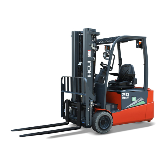
Электропогрузчик heli на российском рынке представлен на 3-ех и 4-ех опорных конструкциях. Такой формат способен поднимать вес в диапазоне 1-7 тонны при стандартной высоте в 7-10 м. Удобство эксплуатации дополняется возможностью работы с грузами практически любого веса.

В дополнение важным аспектом всех электропогрузчиков heli являются их батареи и повышенной емкостью, которые позволяют проработать техническим средствам вплоть до 8-ми часов подряд. При этом не потребуется ни подзарядка, ни остановка во время процесса.
Вилочный электрический heli обладает рядом существенных достоинств:
- Длительные сроки эксплуатации;
- Присутствие плавности и одновременно с этим маневренности при движении;
- Высокая надежность и прочность конструкции;
- Низкая вероятность возникновения ошибок (стандартизированные коды) и простой ремонт;
- Хорошие скоростные показатели при движении с грузами (вплоть до 7 тыс. кг);
- Высокая степень мобильности;
- Соответствие последним тенденциям в области разработки строительной спецтехники.
В инструкцию по эксплуатации вилочного электрического погрузчика хели входит схема зарядного устройства для обеспечения большей степени удобства. Электропогрузчик heli имеет характерные конструктивные особенности, которые заключаются в сдвоенности у ведущих колес. При этом сама техника обладает компактными габаритами, поэтому ее есть смысл купить для условий строительных площадок.
———————————————-
Технические характеристики электропогрузчика HELI CPD20:
|
Грузоподъемность, т |
2,0 |
|
Максимальная высота подъема груза на вилах B, мм |
3000 (2000-7000) |
|
Общая ширина машины Q, мм |
1150 |
|
Длина машины до спинки вил L, мм |
2383 |
|
Высота мачты (в сложенном состоянии) C, мм |
2000 |
|
Колесная база Z, мм |
1500 |
|
Клиренс G, мм |
110 |
|
Угол наклона мачты |
6/12 град. |
|
Радиус поворота (внешний) W, мм |
2050 |
|
Длина вил J, мм |
1070 (920 — 2000) |
|
Аккумулятор, А/ч/V |
600/48 |
|
Вес, кг |
4000 |
|
Двигатель |
|
|
Тип двигателя |
электрический |
|
Тип контроллера |
Zapi (DC) |
|
Трансмиссия (х — ведущее) пер. / зад. |
2x /2 |
|
Двигатель движения/подъема/поворота, кВт |
8 / 8.6 |
Рейтинг: 
![]() Загрузка…
Загрузка…
![]()
Heli H2000 5-10 t Forklift Truck Service Manual PDF
Heli H2000 5-10 t Forklift Truck Service Manual PDF
Heli H2000 5-10 t Forklift Truck Service
Adobe Acrobat Document
10.5 MB
![]()
Heli H2000 2-3.5 t Forklift Truck Parts Catalog PDF
Heli H2000 2-3.5 t Forklift Truck Parts Catalog PDF
Heli H2000 2-3.5 t Forklift Truck Parts
Adobe Acrobat Document
9.6 MB
![]()
Heli H2000 4-5 t Forklift Truck Parts Catalog PDF
Heli H2000 4-5 t Forklift Truck Parts Catalog PDF
Heli H2000 4-5 t Forklift Truck Parts Ca
Adobe Acrobat Document
1.9 MB
![]()
Heli Forklift 1-10 t K series Operator’s Manual
Heli Forklift 1-10t-k-series Operator’s Manual
Heli forklift 1-10t-k-series Operator Ma
Adobe Acrobat Document
3.9 MB
Some HELI Forklift Truck Service Manuals & Parts Catalogs PDF with Wiring Diagrams & Error Codes DTC are above the page.
Anhui Heli Forklift Truck is one of the largest in China for the production of lifting equipment. It was founded in 1958, and the first forklifts were launched in February 1963.
In 1976, the company’s factory began manufacturing the first 20-ton and 25-ton models in China. About 9 years later, according to the technology of the company TCM, production of fork lift trucks with a load capacity of 1-10t began.
Today, Anhui Heli is a large city-forming corporation, which includes about ten factories that produce not only loaders, but also components for them, hardware, frames, balances,
and a number of components for other manufacturers of lifting and transport equipment.
Changed and design approach. Now the company does not manufacture products under license, but uses its own developments and components.
The plant is working on quality, updating the technical base; all production processes are standardized to ISO 9001. At the same time, the process of product modernization is in progress. The
latest range of loaders was released in 2000.
-
Саид


Проблема с Heli CPD18
Добрый день. Очень прошу не отказать в помощи. Вилочный погрузчик Heli CPD18 .
На дисплее выскочила ошибка alarm 86 и вторая строка on mode 2. Прошу подсказать , что означает код ошибки 86? заранее благодарю Вас!!!!
-
Александр Дитюк
- Компания: ООО «Форклифт»
- Должность: Главный инженер
- Откуда: Новосибирск
- Сообщения: 428
- Зарегистрирован: 14 апр 2016, 08:18
- Контактная информация:

Re: Проблема с Heli CPD18
Сообщение Александр Дитюк » 20 сен 2016, 08:40
Здравствуйте.
Ошибка указывает на контакты, провода педали газа.
Что у Вас при этом происходит с машиной?
- Tohib88
- Компания: ОО РИФ
- Должность: Техник
- Сообщения: 2
- Зарегистрирован: 27 июл 2021, 19:58
- Контактная информация:
Re: Проблема с Heli CPD15
Сообщение Tohib88 » 29 сен 2021, 16:23
Выдал ошибку alarm226
on node 2.0
Подскажите, куда копать
Нет хода вперёд -назад, мачта работает, руль работает
- Кокорев Евгений
- Компания: Центр Обучения «Комацу»
- Сообщения: 165
- Зарегистрирован: 09 июн 2020, 16:26
- Контактная информация:

Re: Проблема с Heli CPD18
Сообщение Кокорев Евгений » 30 сен 2021, 17:23
Добрый день, в имеющихся у нас сервисных мануалах эта ошибка не прописана, пробуем запросить у поставщика техники.
Советую обратиться к официальному представителю в Вашем регионе. Сервисный инженер разберется на месте, продиагностировав погрузчик.
- djodjo2014
- Компания: Microcell
- Сообщения: 3
- Зарегистрирован: 31 май 2022, 17:26
- Контактная информация:
Re: Проблема с Heli CPD18
Сообщение djodjo2014 » 09 ноя 2022, 14:33
Добрый день.
У меня вилочный погрузчик heli cpd18
Появилась ошибка alarm 79 on node 2
Подскажите пожалуйста в чём может быть причина и куда копать
- Владимир Владимир
- Компания: форклифт
- Должность: специалист
- Сообщения: 18
- Зарегистрирован: 16 сен 2022, 16:00
- Контактная информация:
Re: Проблема с Heli CPD18
Сообщение Владимир Владимир » 01 дек 2022, 08:53
djodjo2014 писал(а):Добрый день.
У меня вилочный погрузчик heli cpd18
Появилась ошибка alarm 79 on node 2
Подскажите пожалуйста в чём может быть причина и куда копать
Здравствуйте. ошибка alarm 79 on node 2-
Общая неисправность системы передвижения.
Неправильная последовательность запуска
Возможные причины неправильной последовательности запуска:
(1) Переключатель направления перед запуском закрыт.
(2) Неправильная последовательность операций.
(3) Неправильное соединение проводов.
((4) Если неисправность все еще не может быть устранена, замените контроллер
- Владимир Владимир
- Компания: форклифт
- Должность: специалист
- Сообщения: 18
- Зарегистрирован: 16 сен 2022, 16:00
- Контактная информация:
Re: Проблема с Heli CPD18
Сообщение Владимир Владимир » 01 дек 2022, 09:05
djodjo2014 писал(а):Добрый день.
У меня вилочный погрузчик heli cpd18
Появилась ошибка alarm 79 on node 2
Подскажите пожалуйста в чём может быть причина и куда копать
Проще говоря, часто ли оператор погрузчика оставляет включенную передачу, выключает, а затем включает погрузчик с включенной скоростью? Такое бывает, когда оператор нечаянно задевает реверсор переключения при посадке-высадке, а потом запускает машину, и она выдаёт ошибку.
- Геннадийр
- Компания: Уралсервистех
- Должность: Сервисныйинженер
- Сообщения: 1
- Зарегистрирован: 27 дек 2022, 14:27
- Контактная информация:
Re: Проблема с Heli CPD18
Сообщение Геннадийр » 27 дек 2022, 14:32

Модель: Heli cpd15r
Серийный номер: ?
Год выпуска: ?
Ошибка 229 контактор не срабатывает
- Владимир Владимир
- Компания: форклифт
- Должность: специалист
- Сообщения: 18
- Зарегистрирован: 16 сен 2022, 16:00
- Контактная информация:
Re: Проблема с Heli CPD18
Сообщение Владимир Владимир » 29 дек 2022, 12:14
Модель: [info_tech_model=1]Heli cpd15r
Серийный номер: ?
Год выпуска: ?
Ошибка 229 контактор не срабатывает[/quote]
Советую обратиться к официальному представителю в Вашем регионе. Сервисный инженер разберется на месте, продиагностировав погрузчик.
Вернуться в «Вилочные погрузчики»
-
Contents
Table of Contents -
Bookmarks
Quick Links
Related Manuals for HELI CPD15
Summary of Contents for HELI CPD15
-
Page 2
FOREWORD AC type three wheel lithium battery powered forklift truck with front drive is designed on the base of advantages of some trucks made by domestic and foreign manufacturers and developed in introduced technology from abroad to meet the market needs. These trucks are all suited for handling and stacking packed goods in stations, ports, goods yards, warehouses, food processing factory, light and textile industries and other factories. -
Page 3: Table Of Contents
CONTENTS I. Safety Rules for Opeartion and Daily Maintenance of Forklift Truck ……. 2 II. Main Specifications of Forklift Truck …………… 7 III. Construction, Priciple, Adjustment and Maintenance of Forklift Truck ….10 1. Transmission System ………………10 2. Brake System ………………..16 3.
-
Page 4: Safety Rules For Opeartion And Daily Maintenance Of Forklift Truck
Ι. Safety Rules for Operation and Daily Maintenance of Forklift Truck It is important that driver and manager for forklift trucks remember the principle of the “first safety” and ensure the safety operation as the description in 《OPERATION AND SERVICE MANUAL》&《OPERATION MANUAL》. 1.
-
Page 5
(7) Make trying operation of the mast for lifting, lowing and Fwd/Bwd tilting and the truck for steering and braking. 4. Operation of Forklift Truck (1) Only trained and authorized operator shall be permitted to operate the truck. (2) Wear all the safety guards, such as shoes, helmet, clothing and gloves while operating the truck. -
Page 6
necessary. (13) Tilt the mast of the high lift forklift truck as backward as possible while the truck working. Use minimum forward tilt angle and Min. reverse tilt when loading and unloading. (14) Be careful and slowly driving over a dockboard or bridge-plate. (15) Shut down the truck and don’t stay on the truck when checking battery or fuel lever. -
Page 7
b) Check piping, joints, pumps and valves for leaks or damages; c) Check parking brake. The unladen truck can park on the 15% grade ramp, when the parking lever is pulled to the bottom; d) Check instruments, lighting, switches and wiring to see if they work normally or not. -
Page 8
(3)Lubrication chart Note: for the truck without brake liquid, it is not necessary to refer to the chart for relative operation. -
Page 9: Main Specifications Of Forklift Truck
Ⅱ. Main Specifications of Forklift Truck Enternal view of forklift trucks…
-
Page 10
Main specifications Model CPD15 CPD16 CPD18 CPD20 Unit Configuration No. SQ-GB2Li Rated capacity 1500 1600 1800 2000 Load center Power Lithium battery Driving mode Sit-on type Lifting height 3300 Free lift Mast tilting angle (front deg. /rear) Fork size 35× 100× 920 40×… -
Page 11
Dimensions and weight of main dismountable parts CPD15SQ CPD16SQ CPD18SQ CPD20SQ model Unit GB2Li item 410× 1060× 775 425× 1060× 775 455× 1060× 775 Max. overall size Counterweight Weight 1068 980× 190× 522 980× 190× 522 980× 190× 630 980× 190× 630 Assistant Max. -
Page 12: Transmission System
Ⅲ. Construction, Principle, Adjustment and Maintenance of Forklift Trucks 1. Transmission system 1.1 General description The transmission system of the three wheeled forklift truck includes transmission system we call traditionally and brake system. Front wheel dual driving motor structure makes the right and left wheel of three wheeled truck has drive axle, redactor, brake and driving motor independently to improve working efficiency.
-
Page 13
maintenance. 1.2.1 Removal of the wheels Drain off the gear oil inside of the transmission box before disassembling. Loose 6 drive nut and remove drive wheel. Then loose the 7 bolts on frame hexagon socket bolts and remove transmission box connected with travelling motor from frame. Refer to figure 1-1. -
Page 14
1.2.3 Disassembling and assembling of transmission box It is not necessary to disassemble this part normally. If has to, please contact HELI sales company. 1.3 Assembling of transmission system 1.3.1 Assembling of travelling motor… -
Page 15
(3) Screw a new stopping nut (part 4) on and tighten with socket wrench. Tightening torque:55 Nm(M20 × 1,taper φ 25);68 Nm(M14 × 1.5,taper φ 20) (4) Coat O-ring (part 5) slightly with transmission fluid and push it onto centering seat of motor. -
Page 16
The axle is applicable to solid tyre. (1) Clean mating surfaces on wheel shaft and wheel thoroughly and check if it is damaged. (2)The bore pattern in the rim should be in line with the bolts of the wheel shaft; then push the wheel on. -
Page 17
DONAXTM or ATFDEXRONⅡ D-21666 or DONAXTG PLUSD-22543 or DONAXTG D-21126;ESSO TYPESUFFIXA or ATF D-21065 or ATF D-21611 or ATF D-22079. (6)Screw fluid filling plug (part 1) with the sealing ring (part 2).Tightening torque: 22Nm. Refer to figure 1-5. Figure 1-5… -
Page 18: Brake System
2. Brake system 2.1 General description Brake system is made up of service brake and parking brake. 2.1.1Serivce brake The service brake is made up of accelerating pedal, brake pedal, traction controller and traction motor. See the figure below for the service brake principle diagram and the structure of brake pedal.
-
Page 19
Note: It is suggest for driver to getting familiar with the brake effect and functioning without load. 2.1.2 Parking brake Electromagnetic parking brake which is installed on traction motor shaft is applied on three wheeled truck. 1) Automatic parking brake When truck is braked or is stopped, electromagnetic parking brake is applied to lock traction motor output shaft. -
Page 20
Danger: Except under emergency case, it is prohibited to start electromagnetic parking brake through power-off parking brake. When electromagnetic parking brake is applied, do not tow the truck. -
Page 21: Steering System
3. Steering system 3.1 General Description The function of steering system of forklift is to change the driving direction of the forklift or keep the forklift in straight line driving. The performance of steering system directly concerns with the driving safety, operation efficiency of forklifts and labor intensity of drivers.
-
Page 22
hand, the controller provides electrical signal to steering motor to control steer wheels to rotate according to steering wheel operation. It can ensure light and flexible steering at low speed and stable and reliable steering at high speed. 3.3 Composition of Steering System (1) Control mechanism of steering Figure 3-1 Steering unit The steering control mechanism of the truck is mainly composed of steering wheel,… -
Page 23
details). (3) Steering transmission mechanism The steering motor drives meshing gears and then is transmitted to steer wheel. The steering way is simple, easy and convenient. (Refer to the chapter relating to steering axle for more information). 3.4 Integrated electric steering axle The steering rear axle assembly (as shown in Figure 3-2) is composed of steering motor, mechanical structure (including reductor), steering wheel axle and steer wheels and other parts. -
Page 24
Figure 3-2 Electric steering axle (1) Steering motor (2) controller (3) redactor (4) hub assembly 3.5 Adjustment and Maintenance 3.5.1 Rear wheel bearig pre-load adjustment (1) As shown in Fig. 3-3, fill up the chamber formed by wheel hubs, wheel hub bearings and wheel hub covers with lubricating grease. -
Page 25
manually the hub for 3-4turns to ensure its smooth rotation with a specified torque of 2.94-7.8Nm (0.3-0.8kgm). (7) If the torque value necessary to rotate the hub is more than the specified one above-mentioned, screw out the castle nut for 1/6 turn and measure the torque value then. (8) When the torque value measured is up to the specified one, lock the castle nut with a cotter pin. -
Page 26
3.5.3 Steering system troubleshooting Table 3-2 Fault Reasons Remedy No working of steering Check the harness or replace motor No steering No working of steering Check the harness or replace controller Large clearance between Adjust Large noise gears when steering Over wear of gear Replace Make the steering wheel to… -
Page 27: Electric System
4. Electric system 4.1 General description The standard configuration of the electric system include of two controllers. It can succeed in operating the forklift low-noisily, efficiently, smoothly and safety. The electric system is composed of instrument, traction control system, lifting control system, EPS electric steering control system, lithium battery pack, control switch, lighting and wiring harness etc.
-
Page 28
μ ?? ú · ?é è Figure 4-1 Electric system principle diagram(CPD15SQ~20SQ -GB2Li)… -
Page 29
The display implements an interface to the operator through a main page and a number of submenus. a) Turn on the key switch. When the instrument gets power “HELI AC SYSTEM” is displayed on the LED screen. After system self-testing, battery capacity, truck… -
Page 30
Fig. 4-3 Display of the ZAPI instrument when power on (fault-free) b) Battery capacity display: There are 20 grids on the battery capacity indicator. After the truck is powered, the indicator is fully lit (20 grids) if the battery is fully charged. -
Page 31
4.3 Controller 4.3.1 General description The truck adopts the ZAPI ACE2 motor controller imported from Italy, so it has advantages of advanced technology of high frequency MOS tube, superior speed regulating performance, good safety, flexibility and first-class protection etc. The controller assembly includes motor controller, contactor, relay set, fuse ,OPS warning buzzer and the related harness. -
Page 32
; Figure 4-5 CPD15SQ-GB2Li control device assembly… -
Page 33
; Figure 4-6 CPD16SQ-GB2Li control device assembly… -
Page 34
; Figure 4-7 CPD18~20SQ-GB2Li control device assembly… -
Page 35
] 4.4 Motor 4.4.1 Specifications of motors Table 4-2 Specifications of motors Model CPD15~16SQ-GB2Li CPD18~20SQ- GB2Li Item Model of traction motor JXQ-5.4-HL Rated power 5.4kW… -
Page 36
For any questions, please contact the engineers and after sales service of HELI. 1) Battery safety notes (1) Keep the battery away from dangerous goods or environment, such as conductive dust particles, corrosive chemicals, inflammable and explosive materials, dangerous mechanical equipment, high temperature environment, etc;… -
Page 37
(3) Unreasonable use of this series of products may lead to the bulging of the battery unit, and in serious cases, it may lead to the rupture or crack of the plastic shell. At this time, the battery shall be stopped immediately. Please contact the relevant technical department or after-sales service department of our company in time to obtain the treatment method;… -
Page 38
(10) Before using this product, please read the product manual carefully. Children and other untrained personnel are not allowed to use this series of products; (11) It is forbidden to use this series of products in series or parallel with other types of batteries, which may cause personal injury or property loss;… -
Page 39
(5) The self discharge of lithium battery is affected by the ambient temperature and humidity. High temperature and humidity will accelerate the self discharge of lithium battery. It is recommended to store the battery in a dry environment of — 10 ℃ ~ 45 ℃; (6) Non professionals are not allowed to touch, move or disassemble the battery pack and the corresponding high-voltage cable, or other components with high-voltage warning signs;… -
Page 40
(2) The battery shall be charged immediately after use, and shall be fully charged, but overcharge is strictly prohibited; (3) When the truck needs to be stored for a long time, 40% — 60% of the electricity should be kept, please do not fully charge; please fully charge the battery before use; (4) Please check the lithium battery charging socket regularly to ensure that the bracket is not loose, the cover plate of the socket is well sealed, the internal terminal of the socket is not rusted and free of dust, rain and other foreign matters;… -
Page 41
will not be in good contact, resulting in heat or even fire; (4) Do not modify or dismantle the charging port and charging equipment, which may lead to charging failure and fire; (5) In order to avoid serious personal injury, the following precautions should be taken when the truck is charging: a) Do not touch the charging port or the metal terminal in the charging gun;… -
Page 42
4.6 Daily Maintenance (1) Check the wear condition of the contactor. Change it if necessary. Check the contactor every three months. (2) Check the pedals or manual inching switch; measure the voltage drop between the inching switch ends; there is no resistance when the inching switch is closed; there is ringing sound when release. -
Page 43
The manufacturer shall provide quality assurance for the motor controller, and timely inform the manufacturer to provide after-sales service in case of failure; if not authorized and approved by the manufacturer, please do not open the motor controller for maintenance, and the user shall bear the responsibility for personal and property losses caused by the user’s unauthorized maintenance. -
Page 44
Parking brake can be applied only when the truck can not be stopped through braking pedal during travelling. 4.8 Emergency button The emergency power-off switch has the ability to cut off the load current and overload current, which can be used as a safety switch. The emergency power-off switch of the truck has two functions: first, as a safety switch, press the switch in case of emergency to disconnect the battery output, so as to ensure the safety of the whole truck;… -
Page 45
Figure 4-9 Emergency button Danger: Do not press emergency button when travelling. Under certain cases, if emergency button is pressed suddenly, goods may falling down which may cause personnel injury and goods damage. Emergency button can be applied only when the truck can not be stopped with other methods during travelling. -
Page 46
LOGIC Logic card Current protection function failure of logic card: change FAILURE #3 failure 3 the controller. LOGIC Logic card Circuit failure of phase voltage feedback hardware on FAILURE #2 failure 2 logic card. Change the controller. The failure produced when the function of low or over voltage acts. -
Page 47
current micro-control system exceeds the scope allowed for non-operation current. The trouble has nothing to do with the peripheral parts, so the controller needs to be changed. When the electric lock is switch on, inverter will charge the capacitance through power resistance and check if capacitance is fully charged within the time stipulated, otherwise, the capacitance voltage remains 20% lower than battery voltage, the inverter will give alarm and the… -
Page 48
value of parameter “ADJUST BATTERY” of controller is consistent with battery voltage. When electric lock is close, the microprocessor will detect if driver of main contactor is short-circuited and alarm DRIVER Short circuit will be given if yes. Check if there is short circuit on the SHORTED of driver positive pair A 16 of main contactor coil or negative pole. -
Page 49
NODE node signal signal that the other controller can not make normal communication and the controller always is always in the waiting state until CAN communication network is completely normal. Check why the wiring of the modules that fails to communicate is abnormal and see if the software edition or parameter setting is correct. -
Page 50
At start-up stage, if controller detects that there is low logic level signal when key switch is off, there is a fault. Fault analysis: Most possibly is that the voltage is excessively low, suggest to check the followings : (1) If the key switch is based on external load (e.g. the starting of DC-DC converter, the input signal of relay or contactor switch is lower than starting voltage). -
Page 51
OUTPUT safety output Fault analysis: Check if there is short circuit or Low impedance push-pull output betweenA19 and -BATT. If it is the circuit trouble of driver of logic card, change the controller. Before driving the coil of main contactor, controller tests MOS driver or the auxiliary output drive is the invalid HARDWARE Hardware… -
Page 52
The fault has nothing to do with external parts and change the controller. During startup, the controller tests if the voltage of battery is within the nominal scope. Check if the value of WRONG SET Wrong set of BATTERY VOLTAGE parameter in the menu conforms BATTERY battery to that on the voltmeter. -
Page 53
(2) Common fault of pump control system (The second line of instrument indicates “ON NODE 5”) Table 4-6 Common fault of pump control system Fault Implication Note Measures Code The fault is in the internal memory for storing and regulating parameters. When the fault appears, the machine automatically stops. -
Page 54
the ground and circuit break of motor coil. (2) Change the controller The signal output by current sensor detected by High standby micro-control system exceeds the scope allowed for STBY I HIGH current non-operation current. The trouble has nothing to do with the peripheral parts, so the controller needs to be changed. -
Page 55
positive pair A 16 of main contactor coil or negative pole. Change the controller if everything is OK. Detection time : Standby state The alarm indicates the voltage of accelerator is 1V larger than the min. value set in the signal scope (PROGRAM VACC)of accelerator. -
Page 56
INPUT fault contactor, meanwhile the electromagnetic brake or auxiliary output coil is driven. Check if the port of A11 is correctly connected. Change the controller if other parts are correct. At start-up stage, if controller detects that there is low logic level signal when key switch is off, there is a fault. -
Page 57
CHECKSUM Memory fault in flash memory and the fault signal is produced in case of negative value. Fault analysis: The problem is on flash memory of microcontroller. The flash memory may be damaged or the program stored destroyed. Try to reset the program of logic card. -
Page 58
4.9.2 HP-CAN controller This series of controllers can obtain diagnostic information through the times of LED flashes and fault codes sent to the instrument. (1) Common fault of control system (The second line of instrument indicates “ON NODE 5”) Table 4-7 Common fault and remedy of control system CODE NOTE Fault explanation… -
Page 59
● Request microswitch stuck. c) < STANDBY HIGH CURRENT > Test carried out in standby, checks that the current is nil. If this is not verified, an alarm is signalled. This alarm shuts down the machine. Possible causes: ● Current sensor broken and logic failure. First replace the logic, and if the defect persists, replace the power unit. -
Page 60
g) < DRIVER SHORTED > Cause: The driver of the main contactor coil is shorted. Troubleshooting: ● Check if there is a short or a low impedance pull-down between NMC and –BATT. ● The driver circuit is damaged in the controller, which has to be replaced. h) <… -
Page 61
i) < DRIVER SHORTED > Cause: The driver of the main contactor coil is shorted. Troubleshooting: ● Check if there is a short or a low impedance pull-down between NMC (CNA#26) and –BATT. ● The driver circuit is damaged in the controller, which has to be replaced. j) <… -
Page 62
FAILURE #2 failure 2 instrument if it has nothing to do with external components. Drive coil short circuit: Test if there is short circuit COIL SHORT Coil short on the device connecting with output port of the instrument, otherwise, change the instrument. Instrument no longer receives the data from CAN BUS data wire. -
Page 63: Hydraulic System
5 Hydraulic System 5.1 General Description The hydraulic system consists of oil pump, control valve, priority valve, lift cylinder, tilt cylinder, high & low pressure oil pipe an joint etc.The pump is driven directly by the electromotor. The hydraulic oil flow to control valve through the pump and are distribute to cylinders by the control valve.
-
Page 64
cavity, 2 is oil pressing cavity and they are separated by meshing point of two gears. With constant rotation of gear, the suction and discharge outlets of the pump continuously absorb and drain oil. Oil pump is to turn the mechanical energy of motor into hydraulic energy, so the oil pump is the actuating unit of hydraulic system of the forklift. -
Page 65
5.1.2 Control Valve The external of the control valve as shown in Fig. 5-3. Tilting sliding valve lifting sliding valve Main safety valve Figure 5-3 Control valve The control valve adopts two pieces and four body type. The hydraulic oil from working pump distributes the high-pressure oil to the lifting cylinder or tilting cylinder through the control of valve stem. -
Page 66
(1) Spool operation (take the tilt spool valve for example) a) Neutral position (See Fig. 5-4) The high-pressure oil from lift pump returns to the oil tank through the mid-passage. Fig. 5-4 Neutral position b) Pushing-in of spool (See Fig. 5-5) In this time, the spool is pushed in to close the mid-passage. -
Page 67
(2) Motion of safety relief valve The relief valve is mounted between “HP” nozzle of oil pump and “LP” passage. Oil passing through lifting valve C acts on different areas of diameters “A” and “B”, thus, “K” of check valve and “D” of overflow lift valve are on the valve seat as shown in Fig. 5-7. When the pressure regulated in “HP”… -
Page 68
(3) Action of tilt-lock valve Tilt spool valve housing contains a tilt-lock valve. The tilt lock valve is intended to prevent vibrations of the mast resulting from the negative pressure in the tilt cylinder and also to avoid danger incurred from mishandling of the spool. When the lift motor isn’t running, the mast doesn’t be tilted forward by push the tilt lever. -
Page 69
together with a shaft and the shaft is assembled on the valve joint plate with the bracket. The valve levers operate the control valve with the joints. (See Fig. 5-13) Figure 5-13 Control valve As you see in Fig. 5-14, the mast lift up when you push the lift lever forward, the mast fall down when you pull the lift lever backward. -
Page 70
(5) Setting pressure of the control valve (See Fig. 5-15) The pressure of the safety valve shall not be adjusted by non-professional personnel. The adjustment shall follow following procedures: a) Screw off the plug of the measuring hole on the inlet of the control valve. Install an oil pressure gauge capable of measuring 25MPa. -
Page 71
When the hoist valve of control valve is placed at lifting position, hydraulic oil enters into the lower part of piston of hydraulic cylinder from pressure-gradient control valve to selector valve to push rising of piston and lifting of the goods. When the hoist valve of control valve is placed at descending position, the piston rod drops with the action of goods, mast, fork bracket and piston itself, the hydraulic oil is pressed back to oil tank. -
Page 72
5.1.4 Cut-off valve The cut-off valve is mounted at the bottom of the cylinder (See Fig. 5-17) to prevent the goods from falling suddenly when the high pressure pipe is broken. The oil from hoist cylinder passes through the hole A on the outer circumference of the spool when returning to oil tank, if flow rate of oil through the hole is less than the setting value of the valve and the pressure difference before and after spool smaller than spring force, the spool will not move at this time and slide valve does not work. -
Page 73
the lift cylinder without any regulation. When the lift spool is placed in the “down” position, the oil pusses the orifice plate and a pressure difference generates between the chambers A and B, the pressure difference overcomes the force of the spring and moves the valve core right, thus the oil flow being decreased by narrowing of the hole D and C, and reduces the oil flow passing through the orifice plate. -
Page 74
difference between the dip angles. (See Fig. 5-19) When the tilt lever is pushed forward, the high-pressure oil enters into the cylinder body from the cylinder tail, moving the piston forward and causing the mast assembly to tilt forward until 6 degrees. When the tilt lever is pulled backward, high-pressure oil enters into the cylinder body from the guide sleeve and moves the piston backward, tilting the mast assembly backward. -
Page 75
Fig. 5-20 Hydraulic system principle diagram (1) Oil tank (2) Oil suction filter (3) Pump motor (4) Gear pump (5) Control valve (6) Flow regulator valve (7) Cut-off valve (8) Lift cylinder (11) Tilt cylinder Return oil filter (12) -
Page 76
Figure 5-21 Hydraulic pipeline 5.2 Maintenance,Fault Analysis and Remedies 5.2.1 Maintenance Check if there is any seepage and serious oil leakage on the pipe fittings of hydraulic drive system, hoist cylinder, tilt cylinder, oil pump, before and after each shift. Check if the working oil inside work oil tank is sufficient and check and clean the strainer mesh of oil filter mounted in the work oil tank once every week. -
Page 77
Before disassembling the pump, put the removed parts on the paper or cloth. Don’t damage the parts. (See Fig. 5-23) a) Hold the pump cleaned in a vice by lightly clamping the flange section. b) Remove bolts 11, pump cover 5, pump body 1. c) Remove lining plate 6, drive gear2, driven gear 3. -
Page 78
(2) Inspection Check the disassembled parts and wash them with light oil. Don’t wash the rubber items with light oil. a) Body inspection (See Fig. 5-23) If the contact length between pump body lumen and gear longer than 1/2 long of the perimeter, replace the pump body. -
Page 79
e) Replace seal rings, bushings, seal rings, rings, oil seals and snap rings as required. Fig. 5-27 (3) Reassembly a) Fixed the front cover on the clamping. (See Fig. 5-28) Fig. 5-28 b) Install a new seal ring on the front cover of the pump. -
Page 80
f) Install the drive gearon the pump body with the side of the spline downward. Fig. 5-33 g) Install the driven gear on the pump body as the direction shown in Fig. 5-34. Fig. 5-34 Install the lining plate on the side of the gear, don’t confuse the inlet oil port and the outlet oil port. -
Page 81
k) Tighten up the connecting bolts with a specified torque of 9 to 10kg.m after all. Fig. 5-38 l) Take down the pump from the clamping. Apply lubricating grease on the outside circle and lip of the oil seal, install it on the front cover with mould. -
Page 82
~ c) Increase the pump speed to 1500 2000rpm for 10 minutes. ~ d) Make the pump running at a speed of 1500 2000rpm for 5 minutes and increase the pressure to 210kg/ cm by 20~30kg/cm each time. Then make each oil circuit works for 5 minutes and then change the oil filter. -
Page 83
5.2.3 Troubleshooting Trouble Cause Trouble shooting 1) Excessive wearing between the oil 1) Replace the wearable parts or oil pump gear pump body pump. wider-than-normal gap. 2) Wearing and wider-than-normal gap of 2) Replace with new piston sealing ring. the piston sealing part in the lifting cylinder, excessive inner leakage. -
Page 84: Lifting System
6. Lifting system 6.1 Normal type lifting system general description Normal type lifting system is of two stage roller type with veritical up and down moving. It is made up of inner mast, outer mast, two rear lifting cylinder and fork brakcet.
-
Page 85
6.3 Fork bracket The fork bracket runs inside of the iner mast through main roller. The main roller is installed on main roller shaft with snap ring. The main roller is welded on fork bracket. The side roller of upright plate is fixed on forkbracket with bolt. The longitudinal load is beared by main roller. -
Page 86
Combined roller main roller Side roller inner mast outer mast Rear lifting cylinder Push the side roller with round bar through the hole Adjust side roller clearance through adjusting shim Figure 6-3 roller layout Note: (a) side roller clearance is between 0 and 0.5mm. (b) Apply grease on main roller surface and mast conntacting surface. -
Page 87
and 0.5mm). (3) Lower the inner mast slowly and check if two cylinders stroke are synchronous. Refer to the method above to adjust. (4) Adjust chain tensioning. Lifting cylinder adjusting is very important, please take care. Inner mast upper beam Adjusting shim Lifting cylinder Figure 6-4… -
Page 88
Fig. 6-5 Adjust lift bracket’s height 6.5.3 Replacing rollers of the lift bracket (1) Place a salver on the forks and make the forklift stop on the horizontal ground. (2) Make the forks and salver descend to the ground. (3) Take down tie-in on top of the chains. And take out chains from sheave. (See Fig. 6-7) (4) Make the inner mast rise. -
Page 89
6.5.4 Replacing rollers of masts (1) Take apart the fork bracket from the inner mast, then replace the main roller follows the way as 6.5.3. ~ (2) Park the truck on the horizontal ground and lift up the front-wheel 250 300mm from the ground.