Kyocera Taskalfa 3050ci ошибка с7102
после не оригинального тонера пришлось чистить блок проявки.
теперь при запуске выдает ошибку С7102.
что за ошибка? может она быть с отсутствием тонера внутри блока проявки?
- alex-r1
- новичок
- Сообщения: 6
- Зарегистрирован: 02:11 — 13.11.17
- Баллы репутации: 0


Re: Kyocera Taskalfa 3050ci ошибка с7102
![]() pokyocere » 02:04 — 14.11.17
pokyocere » 02:04 — 14.11.17
Я так понимаю, вы полностью очистили блок проявки ?
Если это так, то датчик у вас 100% рабочий, ведь аппарат вам выдал С 7102.
Если вы не готовы потрать на мфу 120 000 р., то тему можно закрывать.
- pokyocere
- новичок
- Сообщения: 43
- Зарегистрирован: 00:45 — 30.08.15
- Баллы репутации: 0
Re: Kyocera Taskalfa 3050ci ошибка с7102
![]() alex-r1 » 02:18 — 14.11.17
alex-r1 » 02:18 — 14.11.17
Если вы не готовы потрать на мфу 120 000 р., то тему можно закрывать.
хороший совет 
то есть заменить developerunit вместе с его :%;:;ми датчиками 20 000 не вариант?
- alex-r1
- новичок
- Сообщения: 6
- Зарегистрирован: 02:11 — 13.11.17
- Баллы репутации: 0
Re: Kyocera Taskalfa 3050ci ошибка с7102
![]() Mishel01 » 14:32 — 14.11.17
Mishel01 » 14:32 — 14.11.17
Весело у вас тут))
Нет, за 20 тыс — не вариант: вы знаете места, где НОВЫЕ 8305тые проявки лежат дешевле чем за 28-29 тыс?
Датчик, в этой ситуации, скорее всего 100% НЕрабочий — потому и выдает ошибки С71хх.
Про 120 тыс — спасибо, посмеялся от души))
- Mishel01
- эксперт
- Сообщения: 8413
- Зарегистрирован: 01:10 — 10.01.11
- Баллы репутации: 1

Re: Kyocera Taskalfa 3050ci ошибка с7102
![]() mark.76 » 14:33 — 14.11.17
mark.76 » 14:33 — 14.11.17
alex-r1 писал(а):после не оригинального тонера пришлось чистить блок проявки.
теперь при запуске выдает ошибку С7102.
что за ошибка? может она быть с отсутствием тонера внутри блока проявки?
1 Если вычистили блок проявки — носитель чистый засыпали?
2 Да именно отсуотствием тонера в блоке проявки и вызвана — Чтобы намешался тонер и аппарат не выпадал в ошибку можно похлопать крышками пока не выйдет на готовность. (для ускорения процесса можно подсыпать тонера прямо в блок, но немного и всё равно похлопать )
www.veneta.ru
- mark.76
- ученик
- Сообщения: 129
- Зарегистрирован: 14:41 — 07.06.07
- Баллы репутации: 0
Re: Kyocera Taskalfa 3050ci ошибка с7102
![]() Mishel01 » 15:35 — 14.11.17
Mishel01 » 15:35 — 14.11.17
Носителя он туда НИКАКОГО не сыпал))
Тонер-то в проявке явно есть, только скушно ему там: не носят его..)) А из состояния ошибки он не будет подмешивать, насколько помню.
- Mishel01
- эксперт
- Сообщения: 8413
- Зарегистрирован: 01:10 — 10.01.11
- Баллы репутации: 1
Re: Kyocera Taskalfa 3050ci ошибка с7102
![]() pokyocere » 22:27 — 14.11.17
pokyocere » 22:27 — 14.11.17
Mishel01 писал(а):Весело у вас тут))
Нет, за 20 тыс — не вариант: вы знаете места, где НОВЫЕ 8305тые проявки лежат дешевле чем за 28-29 тыс?
Датчик, в этой ситуации, скорее всего 100% НЕрабочий — потому и выдает ошибки С71хх.
Про 120 тыс — спасибо, посмеялся от души))
Наивно полагать, что левый тонер, был только синего цвета.
Кто из вас поручится, что после исправления 7102, не начнут гулять другие цвета и не выскочит ошибка по другому блоку ?
Так что, давайте смотреть реально на такие ремонты.
DV-8305 29-30 т.р. х 4 = 116-120 т.р. не обязательно сразу, но в перспективе точно.
Датчик 100% рабочий, он просто не поймет что находится в блоке и инициирует эту ошибку.
Для проверки нужно зайти в U155 и посмотреть показания датчика.
Возьмите рабочий DV, все из него вытряхните, вставьте в аппарат и получите ошибку, а потом утверждайте что датчик 100% не рабочий.
Ведь alex-r1 очень понятно написал «после не оригинального тонера пришлось чистить блок проявки. теперь при запуске выдает ошибку С7102»
Очевидно, что ошибка до чистки отсутствовала . После чистки появилась.
С чего вдруг датчик сломался ?
- pokyocere
- новичок
- Сообщения: 43
- Зарегистрирован: 00:45 — 30.08.15
- Баллы репутации: 0
Re: Kyocera Taskalfa 3050ci ошибка с7102
![]() Mishel01 » 23:32 — 14.11.17
Mishel01 » 23:32 — 14.11.17
«Полагать» — в данном случае совсем не наша забота. Поручаться — тем более. Появится аналогичная проблема по другому цвету — будет ОТДЕЛЬНЫЙ сюжет по уже накатанной дорожке. Куда уж реальнее. Чем менять все 4 — гораздо выгоднее выкинуть данный аппарат и купить другой (нормальный, не Киосеру).
Проверить датчик можно и без вытрахивания, но одного снятия показаний тут будет мало. И не факт, что до чистки ошибки не было.
Если бы я знал точную первопричину выхода из строя этих датчиков — у меня сейчас был бы большой чемодан исправных датчиков))
- Mishel01
- эксперт
- Сообщения: 8413
- Зарегистрирован: 01:10 — 10.01.11
- Баллы репутации: 1
Re: Kyocera Taskalfa 3050ci ошибка с7102
![]() alex-r1 » 02:54 — 15.11.17
alex-r1 » 02:54 — 15.11.17
1 Если вычистили блок проявки — носитель чистый засыпали?
2 Да именно отсуотствием тонера в блоке проявки и вызвана — Чтобы намешался тонер и аппарат не выпадал в ошибку можно похлопать крышками пока не выйдет на готовность. (для ускорения процесса можно подсыпать тонера прямо в блок, но немного и всё равно похлопать
добавления тонера не помогло, в прочем я этого ожидал. как тут говорили тонеру без носителя скучно будет.
да…носитель я не досыпал, у меня его просто нет.
Кто из вас поручится, что после исправления 7102, не начнут гулять другие цвета и не выскочит ошибка по другому блоку ?
Так что, давайте смотреть реально на такие ремонты.
DV-8305 29-30 т.р. х 4 = 116-120 т.р. не обязательно сразу, но в перспективе точно.
все вполне логично. к счастью пострадал только 1 цвет. остальные не успели угробить подделкой. владельцев о проблеме предупредил  ,картриджи изъял .
и все же я надеюсь решить проблему более бюджетным способом.
https://kupi-print.ru/catalog/kyocera_1 … 7978200002
или смесью тонер +девелопер за 2800р.
Последний раз редактировалось alex-r1 03:01 — 15.11.17, всего редактировалось 1 раз.
- alex-r1
- новичок
- Сообщения: 6
- Зарегистрирован: 02:11 — 13.11.17
- Баллы репутации: 0
Re: Kyocera Taskalfa 3050ci ошибка с7102
![]() alex-r1 » 03:00 — 15.11.17
alex-r1 » 03:00 — 15.11.17
Чем менять все 4 — гораздо выгоднее выкинуть данный аппарат и купить другой (нормальный, не Киосеру).
признаюсь Kyocera мне тоже не нравится ( технически). есть рекомендации? приоритет под полиграфию
- alex-r1
- новичок
- Сообщения: 6
- Зарегистрирован: 02:11 — 13.11.17
- Баллы репутации: 0
Re: Kyocera Taskalfa 3050ci ошибка с7102
![]() alex-r1 » 10:47 — 15.11.17
alex-r1 » 10:47 — 15.11.17
и так ситуация все смешнее.
еще вчера сообщил владельцам что причина в нехватке расходных, а это значит доставка из Москвы не меньше месяца.
сегодня он вдруг  вспомнил ,что где-то там у них «что-то»было и достает тубу с девелопером
всыпали грамм 20-30. аппарат запустился.
- alex-r1
- новичок
- Сообщения: 6
- Зарегистрирован: 02:11 — 13.11.17
- Баллы репутации: 0
Re: Kyocera Taskalfa 3050ci ошибка с7102
![]() Mishel01 » 11:34 — 15.11.17
Mishel01 » 11:34 — 15.11.17
alex-r1 писал(а): есть рекомендации? приоритет под полиграфию
Рекомендации будут, сначала жду более подробно о потребностях, пожеланиях, возможностях и проч.
- Mishel01
- эксперт
- Сообщения: 8413
- Зарегистрирован: 01:10 — 10.01.11
- Баллы репутации: 1
Re: Kyocera Taskalfa 3050ci ошибка с7102
![]() gregory » 19:44 — 13.12.17
gregory » 19:44 — 13.12.17
столкнулся с такой же бедой. и тоже неориг тонер с пометкой япония. чем закончились изыскания и способы борьбы?
кстати этот клиент вопреки рекомендациям купить оки и не напрягаться взял киосеру. монохромники обалденные у них а вот цвет капризный (((
- gregory
- новичок
- Сообщения: 5
- Зарегистрирован: 11:15 — 21.01.13
- Баллы репутации: 0
Re: Kyocera Taskalfa 3050ci ошибка с7102
![]() Mishel01 » 22:52 — 13.12.17
Mishel01 » 22:52 — 13.12.17
gregory писал(а): чем закончились изыскания и способы борьбы?
Никаких изысканий и выбора способов тут уже давно не надобно. Все прозрачно и предсказуемо… хоть и печально.
- Mishel01
- эксперт
- Сообщения: 8413
- Зарегистрирован: 01:10 — 10.01.11
- Баллы репутации: 1
Вернуться в KYOCERA
Кто сейчас на конференции
Сейчас этот форум просматривают: нет зарегистрированных пользователей и гости: 0
Все современные копировальные аппараты, мфу и принтеры Kyocera имеют возможность диагностировать все узлы устройства в режиме запуска и во время работы аппарата. По этому, если во время включения или во время работы произошел сбой, то техника Kyocera сможет сообщить о наличии ошибки.
В большинстве случаев у аппаратов Kyocera код ошибки отображается на дисплее, в остальных случаях тип ошибки зависит от последовательности и количества миганий индикаторов.
Если Ваш копировальный аппарат, МФУ или принтер Kyocera выдал на дисплее некий код, то узнать причину, описание возникновения ошибки, а так же в каком узле аппарата стоит искать проблему, Вы можете в этом разделе выбрав интересующую модель из списка.
Но диагностика не решит проблему сбоя аппарата, для этого лучше обратиться к профессиональным и опытным сервисным специалистам компании Kyomart! Позвоните нам по телефону
8 (343) 288-23-45 или отправьте запрос на электронную почту: sales@kyomart.ru , и мы обязательно свяжемся с Вами в кратчайшие сроки.
Processing with the fax software was disabled due to a hardware problem.
Abnormal detection of FAX control PWB incompatibility In the initial communication with the FAX control PWB, any normal communication command is not transmitted.
Defective FAX control PWB.
For data in which the MAC address is invalid.
Defective flash memory.
Defective engine PWB.
Defective main PWB.
Defective main PWB.
Detecting engine PWB EEPROM communication error.
Defective engine PWB.
Device damage of EEPROM.
Defective engine PWB.
A checksum error is detected in the main and engine backup memories for the billing counters.
Defective PWB.
Machine number of main and engine does not match.
A communication error is detected 10 times in succession.
JAM05 is detected twice.
A checksum error occurred with the program of the FAX control PWB.
Defective FAX control PWB.
The time is judged to go back based on the comparison of the RTC time and the current time or five years or more have passed.
Defective main PWB.
High-capacity data transfer between the FAX control PWB and the main PWB of the machine was not normally performed even if the data transfer was retried the specified times.
Defective FAX control PWB or main PWB.
The backup data is not retained for file system abnormality of flash memory of the FAX control PWB.
After cassette 1 is inserted, lift sensor does not turn on within 12 s. This error is detected four times successively.
Defective connector cable or poor contact in the connector.
Defective drive transmission system of the lift motor.
Defective lift motor.
Defective engine PWB.
After cassette 2 is inserted, PF lift sensor 1 does not turn on within 12 s. This error is detected four times successively.
Defective connector cable or poor contact in the connector.
Defective drive transmission system of the PF lift motor 1.
Defective PF lift motor 1.
Defective PF main PWB.
After cassette 3 is inserted, PF lift sensor 2 does not turn on within 12 s. This error is detected four times successively.
Defective connector cable or poor contact in the connector.
Defective drive transmission system of the PF lift motor 2.
Defective PF lift motor 2.
Defective PF main PWB.
A communication error is detected 10 times in succession.
Defective connector cable or poor contact in the connector.
Defective engine PWB.
Defective PF main PWB.
When writing the data, the write data and the read data is not continuously in agreement 5 times.
Device damage of EEPROM.
Stable OFF is detected for 1 s continuously after main motor stabilized.
Defective drive transmission system of the main motor.
Defective main motor.
Defective engine PWB.
The main motor is not stabilized within 2 s after driving starts.
Defective drive transmission system of the main motor.
Defective main motor.
Defective engine PWB.
The rated speed signal detected the stability OFF continuously for 1 s after the developer motor K stabilizes.
Defective drive transmission system.
Defective motor.
Defective PWB.
The rated speed signal detected the stability OFF continuously for 1 s after the developer motor YCM stabilizes.
Defective drive transmission system.
Defective motor.
Defective PWB.
Developer motor K is not stabilized within 2 s since the motor is activated.
Defective drive transmission system.
Defective motor.
Defective PWB.
Developer motor YCM is not stabilized within 2 s since the motor is activated.
Defective drive transmission system.
Defective motor.
Defective PWB.
The rated speed signal detected the stability OFF continuously for 1 s after the fuser motor stabilizes.
Defective drive transmission system.
Defective motor.
Defective PWB.
Fuser motor is not stabilized within 2 s since the motor is activated.
Defective drive transmission system.
Defective motor.
Defective PWB.
The rated speed signal detected the stability OFF continuously for 1 s after the conveying motor stabilizes.
Defective drive transmission system.
Defective motor.
Defective PWB.
Conveying motor is not stabilized within 2 s since the motor is activated.
Defective drive transmission system.
Defective motor.
Defective PWB.
When the PF drive motor is driven, error signal is detected continuously for 1 s.
Defective drive transmission system of the PF drive motor.
Defective PF drive motor.
Defective PF main PWB.
When the TC belt motor is driven, error signal is detected continuously for 1 s.
Defective drive transmission system of the PF drive motor.
Defective PF drive motor.
Defective PF main PWB.
The home position is not correct when the power is turned on or at the start of copying using the table.
Defective home position sensor.
Defective ISU motor.
Defective CCD PWB.
Defective engine PWB.
When input value at the time of exposure lamp illumination does not exceed the threshold value between 5 s.
Defective exposure lamp.
Defective CCD PWB.
Defective main PWB.
An error code is detected 3 times in succession.
Defective CCD PWB.
Defective main PWB.
The polygon motor is not stabilized within 10 s after driving starts.
Defective polygon motor.
Defective engine PWB.
The rated speed signal detected the stability OFF continuously for 1 s after the polygon motor (K) stabilizes.
Defective motor
Defective PWB.
The rated speed signal detected the stability OFF continuously for 1 s after the polygon motor (С) stabilizes.
Defective motor
Defective PWB.
The rated speed signal detected the stability OFF continuously for 1 s after the polygon motor (M) stabilizes.
Defective motor
Defective PWB.
The rated speed signal detected the stability OFF continuously for 1 s after the polygon motor (Y) stabilizes.
Defective motor
Defective PWB.
Stable OFF is detected for 1 s continuously after polygon motor stabilized.
Defective polygon motor.
Defective engine PWB.
Polygon motor (K) is not stabilized within 10 s since the motor is activated.
Defective motor.
Defective PWB.
Polygon motor (C) is not stabilized within 10 s since the motor is activated.
Defective motor.
Defective PWB.
Polygon motor (M) is not stabilized within 10 s since the motor is activated.
Defective motor.
Defective PWB.
Polygon motor (Y) is not stabilized within 10 s since the motor is activated.
Defective motor.
Defective PWB.
BD is not detected within 1 s after polygon motor stabilized.
Defective APC PWB.
Defective BD PWB.
Defective main PWB.
When the LSU cleaning motor is driven, an error signal is detected continuously for 1 s.
Defective drive transmission system.
Defective motor. Defective PWB.
Defective main PWB or engine PWB.
A communication error is detected 10 times in succession.
Defective PWB.
The detected temperature of fuser thermistor does not reach the specified temperature (ready indication temperature) after the fuser heater has been turned on continuously for 60 s in warming up. The fusing temperature at 7 seconds and 20 seconds since fuser temperature control has occurred differs by 43°C/109.4°F or less.
Deformed connector pin.
Defective triac.
Fuser thermostat triggered.
Broken fuser heater wire.
Defective engine PWB.
6020
6030
6050
Abnormally high fuser thermistor temperature Broken fuser thermistor wire Abnormally low fuser thermistor temperature
Defective triac.
The fuser thermistor detects a temperature higher than 230°C/446°F continuously for 40 ms. High fuser temperature signal detects a temperature of 255°C/491°F continuously for 40 ms.
Defective triac.
Shorted fuser thermistor.
Defective engine PWB.
A/D value of the fuser thermistor exceeds 251 bit continuously for 7 s during warming up.
Deformed connector pin.
Defective triac.
Defective fuser thermistor.
Defective engine PWB
As the stable temperature has reached the second time, the decrease in the fuser thermistor temperature of 60°C/140°F or greater is detected for one second.
Defective triac.
Defective fuser thermistor
Defective fuser heater.
Defective engine PWB.
The fuser temperature exceeds 200 °C/392 °F for 1 s.
Defective IH PWB.
Defective fuser thermistor.
Defective engine PWB.
Deformed connector pin.
Defective IH PWB.
Defective fuser thermistor.
Defective engine PWB.
The fuser temperature lower than 30 °C/86 °F is detected continuously for 1 s.
Defective fuser thermistor
Defective fuser heater.
Defective engine PWB.
Fuser thermistor 1 does not reach 50° C/122 °F even after20 s during warming up. The detected temperature of fuser thermistor1 does not reach the specified temperature (ready indication temperature) for 20 s in warming up after reaching 50° C/122 °F.
Deformed connector pin.
Fuser thermostat triggered.
Broken fuser heater wire.
Defective engine PWB.
The fuser temperature exceeds 240 °C/464 °F for 1 s
Deformed connector pin.
Fuser thermostat triggered.
Broken fuser heater wire.
Defective engine PWB.
During warming up a hearter, fuser thermistor 2 detects a temperature of 100 °C/212 °F or higher and, fuser thermistor 1 detects a temperature of 37 °C/99 °F or lower.
Deformed connector pin.
Fuser thermostat triggered.
Broken fuser heater wire.
Defective engine PWB.
The fuser temperature lower than 100 °C/212 °F is detected continuously for 1 s during printing. The fuser temperature lower than 50 °C/122 °F is detected continuously for 1 s during pre-heating.
Deformed connector pin.
Fuser thermostat triggered.
Broken fuser heater wire.
Defective engine PWB.
While fuser heater control is performed, the zero-cross signal is not input within 3 s.
Defective power source PWB or engine PWB.
Absence of the fuser unit is detected.
Different type of the fuser unit is installed.
The belt was detected to stop for 1 s continuously during motor remote is on.
Defective IH belt.
Defective IH PWB.
Defective engine PWB.
Defective PWB.
Defective PWB.
Defective PWB.
Defective PWB.
Absence of the developing unit K is detected.
Different type of the developing unit is installed.
Defective PWB.
Absence of the developing unit C is detected.
Different type of the developing unit is installed.
Defective PWB.
Absence of the developing unit M is detected.
Different type of the developing unit is installed.
Defective PWB.
Absence of the developing unit Y is detected.
Different type of the developing unit is installed.
Defective PWB.
Absence of the drum unit K is detected.
Different type of the drum unit is installed.
Defective PWB.
Absence of the drum unit C is detected.
Different type of the drum unit is installed.
Defective PWB.
Absence of the drum unit M is detected.
Different type of the drum unit is installed.
Defective PWB.
Absence of the drum unit Y is detected.
Different type of the drum unit is installed.
Defective PWB.
Absence of the transfer belt unit is detected.
Different type of the transfer belt unit is installed.
Defective PWB.
Defective PWB.
Defective PWB.
When ID sensor 2 detected CTD is 500 or less.
Defective PWB.
When ID sensor 2 detected CTD is 500 or less.
Defective PWB.
When ID sensor 2 detected CTD is 500 or less.
Defective PWB.
When ID sensor 2 detected CTD is 500 or less.
Defective PWB.
Color registration correction was failed.
Defective PWB.
The thermistor output value is 0.3 V or less.
Defective temperature sensor.
The thermistor output value is 3 V or more.
Defective temperature sensor.
No response is issued from the device in reading/writing for 5 ms or more and this problem is repeated five times successively. Mismatch of reading data from two locations occurs eight times successively. Mismatch between writing data and reading data occurs eight times successively.
Defective drum unit.
No response is issued from the device in reading/writing for 5 ms or more and this problem is repeated five times successively. Mismatch of reading data from two locations occurs eight times successively. Mismatch between writing data and reading data occurs eight times successively.
Defective developer unit.
No response is issued from the device in reading/writing for 5 ms or more and this problem is repeated five times successively. Mismatch of reading data from two locations occurs eight times successively. Mismatch between writing data and reading data occurs eight times successively.
Defective developing PWB.
When the tray elevation motor raises a tray, the ON status of the tray upper limit sensor is detected.
Defective tray upper limit sensor, paper surface sensor 1/2.
Defective DF main PWB.
The belt sensor does not turn on/off within specified time of the belt solenoid turning on.
Defective belt sensor.
Defective belt solenoid.
Defective DF main PWB.
The tray low limit sensor or paper surface sensor 1/2 cannot be detected to be on within 10 s since the tray elevation motor is activated.
Defective connector cable or poor contact in the connector.
The tray elevation motor malfunctions.
Defective tray lower limit sensor, paper surface sensor 1/2.
Defective DF main PWB.
Jam 7012 or 7023 is indicated.
The stapler is blocked with a staple.
The stapler is broken
Defective DF main PWB.
The adjustment sensor 2 does not turn on/off within specified time of the adjustment motor 2 turning on.
Defective adjustment sensor 2.
Defective adjustment motor 2.
Defective DF main PWB.
The adjustment sensor 1 does not turn on/off within specified time of the adjustment motor 1 turning on.
Defective adjustment sensor 1.
Defective adjustment motor 1.
The roller sensor does not turn on/off within specified time of the roller motor turning on.
Defective connector cable or poor contact in the connector.
Defective roller sensor.
Defective roller motor.
Defective DF main PWB.
The slide sensor does not turn on/off within specified time of the slide motor turning on.
Defective slide sensor.
Defective slide motor.
Defective DF main PWB.
Reading from or writing to EEPROM cannot be performed.
A communication error is detected 10 times in succession.
Defective DF main PWB.
Defective engine PWB.
A communication error is detected 10 times in succession.
Defective bridge PWB.
Defective engine PWB.
Defective DF main PWB.
Defective bridge PWB.
A communication error is detected 10 times in succession.
Defective DP main PWB.
Device damage of EEPROM.
Defective operation panel PWB.
Defective engine PWB.
 Thanks: 0
 Likes: 0
 Dislikes: 0
-
06-14-2012
#1
TaskAlfa 250Ci C7102 — C7103 — C7104 Error Codes
Dear All Friends
i have a problem with 250ci (cdc 1725), gaves 7102 — 7103 — 7104
total counter :90000
main fw :2H7_2F00_010.007all toner and dv units motors are working perfect via simulation.
What is ur advices?Best Redards
Serdar
-
06-14-2012
#2
Re: TaskAlfa 250Ci C7102 — C7103 — C7104 Error Codes
How are the values in U155?
If they are nearby 20, you lost the 24V for the tonersensors.
Did someone exchanged the toner container motor in past?
If yet, please check the wiring above the main front pwb, at a few cases in europe, the wiring would damaged by mounting the plastic cover above the main- and sub front pwb….
In worst case, the engine pwb is damaged totally, this happened in france.
-
06-25-2012
#3
Technician
- Rep Power
- 22
Re: TaskAlfa 250Ci C7102 — C7103 — C7104 Error Codes
you must make an Firmwareupdate the new DV -b working only with the new FW
-
06-26-2012
#4
Re: TaskAlfa 250Ci C7102 — C7103 — C7104 Error Codes
Originally Posted by Mike L
you must make an Firmwareupdate the new DV -b working only with the new FW
Mike L,
if you are using the old FW you�ll get C7401 !!!
It�s totally different Errorcode. Unknown Dev-Unit
But he get Tonersensor Errors.Best regards
KYO_OEM
-
12-03-2013
#5
Junior Member
- Rep Power
- 0
Re: TaskAlfa 250Ci C7102 — C7103 — C7104 Error Codes
any news about this problem?i have the same problem C7103(magenta DV)…firmware update,change DV-M but still the errors there…any suggestion?
-
12-04-2013
#6
Re: TaskAlfa 250Ci C7102 — C7103 — C7104 Error Codes
I had a Saturn recently with a dead color developing motor. At first it was giving magenta «Add Toner» indications. With the new motor it changed to C7103, it think.
The secondary problem was that while the color developing units were not agitating, the toner add system had been packing toner into the magenta developing unit. When it couldn’t take any more it compacted the magenta toner in the spout of the toner cartridge. Once the developing motor was turning again, it took about three days to detone the magenta developer to the point where it tried to add magenta toner, unsuccessfully.
My solution to the secondary problem was to beat on the toner cartridge until the agitation mechanism would turn again. =^..^=
If you’d like a serious answer to your request:
1) demonstrate that you’ve read the manual
2) demonstrate that you made some attempt to fix it.
3) if you’re going to ask about jams include the jam code.
4) if you’re going to ask about an error code include the error code.
5) You are the person onsite. Only you can make observations.
blackcat: Master Of The Obvious =^..^=
-
05-20-2016
#7
Trusted Tech
50+ Posts
- Rep Power
- 23
Re: TaskAlfa 250Ci C7102 — C7103 — C7104 Error Codes
Hello,
I have a problem with a C7103 on a TA 250ci.
I got in U155 (Toner senor output) «26» instead of «+300».
I tried the DV M in another TA300ci and there is de DV M working perfect!
I changed also the engine pwb without result, changed the DV CMY color motor, front main/sub pcb, motor control pwb without result.
Could it be a broken gear in the main imaging drive unit?
This is my last option because it’s a lot of work to disamble this unit!Before i had also C2810. I cleaned the waste toner pipe of the ICL motor. It was stuck with toner. (I did the spring back inside)
thx.
-
05-21-2016
#8
Re: TaskAlfa 250Ci C7102 — C7103 — C7104 Error Codes
The Voyager and VoyagerE series both used to shatter the color developer drive gear, but the Saturn series doesn’t seem to do that in my experience. More common is motor failures. Since there are several motors of the same type, I would remove the back to see if the color developer motor is turning. If no, I would swap around the color developing motor to see if a different motor will turn. =^..^=
If you’d like a serious answer to your request:
1) demonstrate that you’ve read the manual
2) demonstrate that you made some attempt to fix it.
3) if you’re going to ask about jams include the jam code.
4) if you’re going to ask about an error code include the error code.
5) You are the person onsite. Only you can make observations.
blackcat: Master Of The Obvious =^..^=
-
05-21-2016
#9
Trusted Tech
50+ Posts
- Rep Power
- 23
Re: TaskAlfa 250Ci C7102 — C7103 — C7104 Error Codes
Hello blackcat,
I’ve changed already the CMY DV motor without result…
Monday i go back and change the DV M unit with a new one (not a used one).
I can still print in B&W.
-
05-23-2016
#10
Trusted Tech
50+ Posts
- Rep Power
- 23
Re: TaskAlfa 250Ci C7102 — C7103 — C7104 Error Codes
Hello,
Problem solved by swapping the green relay pwb (next to the orange relay pwb) who’s connecting the drums and dv’s.
DV Magenta toner values again +400.
Anyway thx to all!


Bookmarks
Bookmarks
Posting Permissions

- You may not post new threads
- You may not post replies
- You may not post attachments
- You may not edit your posts
- BB code is On
- Smilies are On
- [IMG] code is On
- [VIDEO] code is On
- HTML code is Off
Forum Rules
- Code: C0070
- Description: FAX PWB incompatible detection error
- Causes: Abnormal detection of FAX control PWB incompatibility in the initial communication with the FAX control PWB, any normal communication command is not transmitted.
- Remedy: 1 Checking the FAX PWB The incompatible FAX PWB is installed. Install the FAX PWB for the applicable model. 2 Firmware upgrade The FAX firmware is faulty. Reinstall the FAX firmware. 3 Replacing the main PWB The main PWB is faulty. Replace the main PWB.
- Code: C0100
- Description: Backup memory device error
- Causes: An abnormal status is output from the flash memory.
- Remedy: 1 Resetting the main power The flash memory does not operate properly. Turn off the power switch and unplug the power plug. After 5s passes, reconnect the power plug and turn on the power switch. 2 Checking the main PWB The connector or the FFC is not connected properly. Or, the wire, FFC, the PWB is faulty. Clean the terminal of the connectors on the main PWB, reconnect the connector of the wire, and reconnect the FFC terminal. If the wire or the FFC is faulty, repair or replace them. If not resolved, replace the main PWB.
- Code: C0120
- Description: MAC address data error
- Causes: The MAC address data is incorrect.
- Remedy: 1 Resetting the main power The flash memory does not operate properly. Turn off the power switch and unplug the power plug. After 5s passes, reconnect the power plug and turn on the power switch. 2 Checking the MAC address The MAC address is incorrect. Replace the main PWB when the MAC address is not indicated on the network status page.
- Code: C0130
- Description: Backup memory reading/writing error
- Causes: The reading or writing into the flash memory is unavailable.
- Remedy: 1 Resetting the main power The flash memory does not operate properly. Turn off the power switch and unplug the power plug. After 5s passes, reconnect the power plug and turn on the power switch. 2 Checking the main PWB The connector or the FFC is not connected properly. Or, the wire, FFC, the PWB is faulty. Clean the terminal of the connectors on the main PWB, reconnect the connector of the wire, and reconnect the FFC terminal. If the wire or the FFC is faulty, repair or replace them. If not resolved, replace the main PWB.
- Code: C0140
- Description: Backup memory data error
- Causes: The flash memory data read at the initial start-up is faulty
- Remedy: 1 Resetting the main power The flash memory does not operate properly. Turn off the power switch and unplug the power plug. After 5s passes, reconnect the power plug and turn on the power switch. 2 Checking the main PWB The connector or the FFC is not connected properly. Or, the wire, FFC, the PWB is faulty. Clean the terminal of the connectors on the main PWB, reconnect the connector of the wire, and reconnect the FFC terminal. If the wire or the FFC is faulty, repair or replace them. If not resolved, replace the main PWB.
- Code: C0150
- Description: Engine EEPROM reading / writing error
- Causes: 1. Continuous five times detection of no response from the device for 5ms or more on reading / writing. 2. Data read twice do not match continuous 8 times. 3. Writing data and reading data do not match continuous 8 times.
- Remedy: 1 Resetting the main power The EEPROM on the engine PWB does not operate properly. Turn off the power switch and unplug the power plug. After 5s passes, reconnect the power plug and turn on the power switch. 2 Checking the EEPROM on the engine PWB The EEPROM is not properly attached. Reattach the EEPROM on the engine PWB. 3 Replacing the EEPROM The EEPROM is faulty. 1. Print Maintenance Report at U000 beforehand. 2. Replace the EEPROM on the engine PWB. C6990 appears when turning the power on. Execute U169 at that state. 3. Then, print Maintenance Report at U000. Compare the setting values with Maintenance Report printed before and change the different values. (Target maintenance mode: U063, U100, U127, U140, U161, U465, U468 and U901, etc.) 4. Check the output image and adjust the image at U410, U411, etc. if necessary. 4 Replacing the engine PWB The engine PWB is faulty. Replace the engine PWB.
- Code: C0160
- Description: EEPROM data error
- Causes: The data read from the EEPROM is judged as abnormal.
- Remedy: 1 Resetting the main power The EEPROM on the engine PWB does not operate properly. Turn off the power switch and unplug the power plug. After 5s passes, reconnect the power plug and turn on the power switch. 2 Executing U021 The storage data in the EEPROM on the engine PWB is faulty. Execute U021. 3 Replacing the EEPROM The EEPROM is faulty. 1. Print Maintenance Report at U000 beforehand. 2. Replace the EEPROM on the engine PWB. C6990 appears when turning the power on. Execute U169 at that state. 3. Then, print Maintenance Report at U000. Compare the setting values with Maintenance Report printed before and change the different values. (Target maintenance mode: U063, U100, U127, U140, U161, U465, U468 and U901, etc.) 4. Check the output image and adjust the image at U410, U411, etc. if necessary. 4 Replacing the engine PWB The engine PWB is faulty. Replace the engine PWB.
- Code: C0170
- Description: Charger count error
- Causes: 1. Errors are detected in both backup memory of the engine PWB charge counter and main PWB charge counter. 2. Main PWB counter data and engine PWB counter date are faulty
- Remedy: 1 Replacing the main PWB The main PWB is faulty. Replace the main PWB and execute U004 2 Replacing the EEPROM on the engine PWB The EEPROM is faulty. 1. Print Maintenance Report at U000 beforehand. 2. Replace the EEPROM on the engine PWB. C6990 appears when turning the power on. Execute U169 at that state. 3. Then, print Maintenance Report at U000. Compare the setting values with Maintenance Report printed before and change the different values. (Target maintenance mode: U063, U100, U127, U140, U161, U465, U468 and U901, etc.) 4. Check the output image and adjust the image at U410, U411, etc. if necessary. 3 Replacing the engine PWB The engine PWB is faulty. Replace the engine PWB.
- Code: C0180
- Description: Machine serial number mismatch
- Causes: The machine serial Nos. in the main PWB and the EEPROM on the engine PWB mismatch when turning the power on.
- Remedy: 1 Checking the machine serial No. of the main PWB The main PWB for the different main unit is installed. Check the machine serial Nos of MAIN and ENGINE at U004, and install the correct main PWB if the MAIN No. differs. 2 Checking the machine serial No. in the EEPROM on the engine PWB The EEPROM for the different main unit is installed. Check the machine serial Nos of MAIN and ENGINE at U004, and install the correct EEPROM on the engine PWB if the ENGINE machine serial No. differs. 3 Replacing the main PWB The main PWB is faulty. When the MAIN machine serial No. differs at U004, replace the main PWB and execute U004. 4 Checking the EEPROM on the engine PWB The EEPROM is faulty. If the machine serial number on the engine PWB is different at U004, reattach the EEPROM. If not repaired, replace the EEPROM on the engine PWB by referring to the following procedures. 1. Print Maintenance Report at U000 beforehand. 2. Replace the EEPROM on the engine PWB. C6990 appears when turning the power on. Execute U169 at that state. 3. Then, print Maintenance Report at U000. Compare the setting values with Maintenance Report printed before and change the different values. (Target maintenance mode: U063, U100, U127, U140, U161, U465, U468 and U901, etc.) 4. Check the output image and adjust the image at U410, U411, etc. if necessary. 5 Replacing the engine PWB The engine PWB is faulty. Replace the engine PWB.
- Code: C0190
- Description: Backup memory device error (Engine)
- Causes: Data from the main unit IC cannot be read out at power-up
- Remedy: 1 Resetting the main power The IC in the engine PWB does not operate normally Turn off the power switch and unplug the power plug. After 5s passes, reconnect the power plug and turn on the power switch. 2 Replacing the engine PWB The engine PWB is faulty. Replace the engine PWB.
- Code: C0500
- Description: Drive lock detected by the engine firmware
- Causes: During the engine steady state control, the main motor drive continued 60 minutes or more (except during the maintenance mode)
- Remedy: 1 Resetting the main power The firmware in the engine PWB does not operate normally Turn off the power switch and unplug the power plug. After 5s passes, reconnect the power plug and turn on the power switch. 2 Replacing the engine PWB The engine PWB is faulty. Replace the engine PWB.
- Code: C0510
- Description: Main charger control error
- Causes: The main charger bias turns on while the drum stops.
- Remedy: 1 Resetting the main power The firmware in the engine PWB does not operate normally Turn off the power switch and unplug the power plug. After 5s passes, reconnect the power plug and turn on the power switch. 2 Replacing the engine PWB The engine PWB is faulty. Replace the engine PWB.
- Code: C0520
- Description: Developer control error
- Causes: The developer bias off is detected during the main charge bias off
- Remedy: 1 Resetting the main power The firmware in the engine PWB does not operate normally Turn off the power switch and unplug the power plug. After 5s passes, reconnect the power plug and turn on the power switch. 2 Replacing the engine PWB The engine PWB is faulty. Replace the engine PWB.
- Code: C0530
- Description: Backup task error
- Causes: No operation 30s or more when monitoring the backup task operation
- Remedy: 1 Resetting the main power The firmware in the engine PWB does not operate normally Turn off the power switch and unplug the power plug. After 5s passes, reconnect the power plug and turn on the power switch. 2 Replacing the engine PWB The engine PWB is faulty. Replace the engine PWB.
- Code: C0800
- Description: Image processing error
- Causes: The print sequence jam (J010x) is detected 2 times continuously.
- Remedy: 1 Checking the image data The image data is faulty. When this issue occurs only when handling the certain image data, check if the image data is faulty. 2 Checking the situation The printing operation of the certain file is faulty. Acquire the job’s log if the phenomenon can be reproduced by specifying the job when the error was detected. 3 Checking the main PWB The connector or the FFC is not connected properly. Or, the wire, FFC, the PWB is faulty. Clean the terminal of the connectors on the main PWB, reconnect the connector of the wire, and reconnect the FFC terminal. If the wire or the FFC is faulty, repair or replace them. If not resolved, replace the main PWB.
- Code: C0830
- Description: FAX PWB flash program area checksum error
- Causes: The program stored in the flash memory on the FAX PWB is broken so it cannot perform.
- Remedy: 1 Resetting the main power The FAX PWB is not connected properly. Turn off the power switch and pull out the power plug. After passing 5s, reattach the FAX PWB and reinsert the power plug. Then, turn on the power switch. 2 Firmware upgrade The firmware is faulty. Reinstall the FAX firmware. 3 Initializing the fax The data in the FAX PWB is faulty. Execute U600 to initialize the FAX. 4 Replacing the FAX PWB The FAX PWB is faulty. Replace the FAX PWB. Step
- Code: C0840
- Description: RTC error
- Causes: • Not communicated with RTC correctly. • RTC data is inconsistent with empty battery.
- Remedy: 1 Setting time and date (RTC) Time and date (RTC) are erased Set Date and Time (RTC) from System Menu 2 Replacing the main PWB The main PWB is faulty, or the backup battery runs out. Replacing the main PWB
- Code: C0870
- Description: PC FAX Image data transmission error
- Causes: Data was not properly transmitted even if the specified times of retry were made when the large volume data is transmitted between the FAX PWB and the main PWB.
- Remedy: 1 Resetting the main power The FAX PWB does not operate properly. Turn off the power switch and pull out the power plug. After passing 5s, reattach the FAX PWB and reinsert the power plug. Then, turn on the power switch. 2 Initializing the fax The data in the FAX PWB is faulty. Execute U600 to initialize the FAX. 3 Firmware upgrade The FAX firmware is faulty. Upgrade the fax firmware to the latest version. 4 Replacing the FAX PWB The FAX PWB is faulty. Replace the FAX PWB. 5 Replacing the main PWB The main PWB is faulty. Replace the main PWB.
- Code: C0920
- Description: FAX file system error
- Causes: The backup data could not be stored since the file system of the flash memory is faulty.
- Remedy: 1 Resetting the main power The FAX PWB does not operate properly. Turn off the power switch and pull out the power plug. After passing 5s, reattach the FAX PWB and reinsert the power plug. Then, turn on the power switch. 2 Initializing the fax FAX control values are incorrect Execute U600 to initialize the FAX. 3 Reconnecting the FAX PWB The FAX PWB is not connected properly. Reinstall FAX PWB to Main PWB. 4 Firmware upgrade The firmware is faulty. Reinstall the FAX firmware. 5 Replacing the FAX PWB The FAX PWB is faulty. Replace the FAX PWB.
- Code: C0980
- Description: 24V power interruption detection
- Causes: • 24V power shutoff signal is detected 1s continuously. • Other service call error occurs after 24V power shutoff signal is lowered, and then 24V power is recovered.
- Remedy: 1 Resetting the main power The firmware in the engine PWB does not operate normally Turn off the power switch and unplug the power plug. After 5s passes, reconnect the power plug and turn on the power switch. 2 Checking the connection The connector is not connected properly, or the wire is faulty. Clean the terminal of the wire connectors and reconnect the connectors. If there is no continuity, replace the wire. • Low-voltage PWB — Engine PWB 3 Replacing the low voltage PWB The low voltage PWB is faulty. When the +24V generation from the low voltage PWB is not stable, and it lowers, replace the low voltage PWB. 4 Replacing the engine PWB The engine PWB is faulty. Replace the engine PWB.
- Code: C1010
- Description: Lift motor 1 error
- Causes: • Cassette 1 lift motor over-current is detected 5 times continuously. • Lift sensor on is not detected 5 times continuously when passing 15s after cassette 1 is loaded.
- Remedy: 1 Checking the lift plate The lift plate does not operate properly. Repair or replace the lift plate when it does not move vertically. 2 Checking the connection The connector is not connected properly, or the wire is faulty. Clean the terminal of the following wire connectors and reconnect the connectors. If there is no continuity, replace the wire. • Lift motor — Engine PWB(YC15) • Lift sensor — Engine PWB(YC15) 3 Checking the lift motor The lift motor is faulty. Check the lift motor operation, and replace it if necessary. 4 Checking the lift sensor The lift sensor is not properly attached, or it is faulty. Reattach PF lift upper limit sensor. If not repaired, replace it. 5 Firmware upgrade The firmware is not the latest version. Upgrade the engine firmware to the latest version 6 Replacing the engine PWB The engine PWB is faulty. Replace the engine PWB.
- Code: C1020
- Description: PF lift motor 1 error Object: 500-sheet paper feeder, 500-sheetx2 paper feeder
- Causes: The PF lift sensor 1 on is not detected 5 times continuously when passing 15s after loading cassette 2.
- Remedy: 1 Checking the lift plate The lift plate does not operate properly. Repair or replace the lift plate when it does not move vertically. 2 Checking the connection The connector is not connected properly, or the wire is faulty. Clean the terminal of the following wire connectors and reconnect the connectors. If there is no continuity, replace the wire. • PF lift moor 1 — PF PWB (YC4) • PF upper limit sensor 1 — PF PWB (YC3) 3 Checking PF lift motor 1 PF lift motor 1 is faulty. Check the operation of lift motor 1, and replace it if necessary. 4 Checking PF lift sensor 1 PF lift sensor 1 is not properly attached, or it is faulty. Reattach PF lift sensor 1. If not repaired, replace it. 5 PF firmware upgrade The PF firmware is not the latest version. Upgrade the PF firmware to the latest version. 6 Replacing the PF PWB The PF PWB is faulty. Replace the PF PWB.
- Code: C1030
- Description: PF lift motor 2 error Object: 500-sheetx2 paper feeder
- Causes: The PF lift sensor 2 on is not detected 5 times continuously when passing 15s after loading cassette 3.
- Remedy: 1 Checking the lift plate The lift plate does not operate properly. Repair or replace the lift plate when it does not move vertically. 2 Checking the connection The connector is not connected properly, or the wire is faulty. Clean the terminal of the following wire connectors and reconnect the connectors. If there is no continuity, replace the wire. • PF lift moor 2 — PF PWB (YC6) • PF upper limit sensor 2 — PF PWB (YC5) 3 Checking PF lift motor 2 PF lift motor 2 is faulty. Check the operation of lift motor 2, and replace it if necessary. 4 Checking PF lift sensor 2 PF lift sensor 2 is not properly attached, or it is faulty. Reattach PF lift sensor 2. If not repaired, replace it. 5 PF firmware upgrade The PF firmware is not the latest version. Upgrade the PF firmware to the latest version. 6 Replacing the PF PWB The PF PWB is faulty. Replace the PF PWB.
- Code: C1800
- Description: Paper Feeder communication error Object: 500-sheet paper feeder, 500-sheetx2 paper feeder
- Causes: The communication error was detected 10 times continuously.
- Remedy: 1 Checking the connection The connector is not connected properly, or the wire is faulty. Clean the terminal of the following wire connectors and reconnect the connectors. If there is no continuity, replace the wire. • Engine PWB (YC25) — PF PWB(YC1) 2 Firmware upgrade The firmware is not the latest version. Upgrade the engine firmware and PF firmware to the latest version 3 Replacing the PF PWB The PF PWB is faulty. Replace the PF PWB. 4 Replacing the engine PWB The engine PWB is faulty. Replace the engine PWB.
- Code: C1900
- Description: Paper Feeder EEPROM error Object: 500-sheet paper feeder, 500-sheetx2 paper feeder For internal count
- Causes: The writing data and the reading data mismatch 4 times continuously when writing.
- Remedy: 1 Checking the connection The connector is not connected properly, or the wire is faulty. Clean the terminal of the following wire connectors and reconnect the connectors. If there is no continuity, replace the wire. • Engine PWB (YC25) — PF PWB(YC1) 2 Firmware upgrade The firmware is not the latest version. Upgrade the engine firmware and PF firmware to the latest version 3 Replacing the PF PWB The PF PWB is faulty. Replace the PF PWB. 4 Replacing the engine PWB The engine PWB is faulty. Replace the engine PWB.
- Code: C2101
- Description: Developer motor K steady-state error
- Causes: Developer motor K steady state off is detected for 1s continuously after becoming the steady state.
- Remedy: 1 Firmware upgrade The firmware is not the latest version. Upgrade the engine firmware to the latest version 2 Checking the connection The connector is not connected properly, or the wire is faulty. Clean the terminal of the following wire connectors and reconnect the connectors. If there is no continuity, replace the wire. • Developer motor K — Engine PWB (YC18) 3 Checking the drive unit The drive unit is faulty. Execute U030 [Dlp(K)/Drum] and check the developer motor K operation. If there are any load for the gear rotation inside the drive unit replace drive unit B. 4 Replacing the developer motor The developer motor is faulty. Replace developer motor K. 5 Replacing the engine PWB The engine PWB is faulty. Replace the engine PWB.
- Code: C2102
- Description: Developer motor CMY steady-state error
- Causes: Developer motor CMY steady state off is detected 1s continuously after becoming the steady state.
- Remedy: 1 Firmware upgrade The firmware is not the latest version. Upgrade the engine firmware to the latest version 2 Checking the connection The connector is not connected properly, or the wire is faulty. Clean the terminal of the following wire connectors and reconnect the connectors. If there is no continuity, replace the wire. • Developer motor CMY — Engine PWB (YC19) 3 Checking the drive unit The drive unit is faulty. Execute U030 [Dlp(Col)] and check the drum motor CMY operation. If there are any load for the gear rotation inside the drive unit replace drive unit A. 4 Replacing the developer motor The developer motor is faulty. Replace developer motor CMY. 5 Replacing the engine PWB The engine PWB is faulty. Replace the engine PWB.
- Code: C2201
- Description: Drum motor K steady-state error
- Causes: Drum motor K steady state off is detected for 1s continuously after becoming the steady state.
- Remedy: 1 Firmware upgrade The firmware is not the latest version. Upgrade the engine firmware to the latest version 2 Checking the connection The connector is not connected properly, or the wire is faulty. Clean the terminal of the following wire connectors and reconnect the connectors. If there is no continuity, replace the wire. • Drum motor K — Engine PWB (YC19) 3 Checking the drive unit The drive unit is faulty. Execute U030 [Dlp(K)/Drum] and check the drum motor K operation. If there are any load for the gear rotation inside the drive unit replace drive unit A. 4 Replacing drum motor K Drum motor K is faulty. Replace drum motor K. 5 Replacing the engine PWB The engine PWB is faulty. Replace the engine PWB.
- Code: C2202
- Description: Drum motor CMY steady-state error
- Causes: Drum motor CMY steady state off is detected 1s continuously after becoming the steady state.
- Remedy: 1 Firmware upgrade The firmware is not the latest version. Upgrade the engine firmware to the latest version 2 Checking the connection The connector is not connected properly, or the wire is faulty. Clean the terminal of the following wire connectors and reconnect the connectors. If there is no continuity, replace the wire. • Drum motor CMY — Engine PWB (YC19) 3 Checking the drive unit The drive unit is faulty. Execute U030 [Dlp(K)/Drum] and check the drum motor CMY operation. If there are any load for the gear rotation inside the drive unit replace drive unit A. 4 Replacing drum motor CMY Drum motor CMY are faulty. Replace drum motor CMY. 5 Replacing the engine PWB The engine PWB is faulty. Replace the engine PWB.
- Code: C2300
- Description: Fuser motor steady state error
- Causes: The fuser motor steady state off is detected 1s continuously after becoming steady state
- Remedy: 1 Firmware upgrade The firmware is not the latest version. Upgrade the engine firmware to the latest version 2 Checking the connection The connector is not connected properly, or the wire is faulty. Clean the terminal of the following wire connectors and reconnect the connectors. If there is no continuity, replace the wire. • Fuser motor — Engine PWB (YC18) 3 Checking the drive unit The drive unit is faulty. Check the fuser motor operation. If there are any load for the gear rotation inside the drive unit replace drive unit B. 4 Replacing the fuser motor The fuser motor is faulty. Replace the fuser motor. 5 Replacing the engine PWB The engine PWB is faulty. Replace the engine PWB.
- Code: C2310
- Description: Fuser motor start-up error
- Causes: The fuser motor is not in the steady state within 1.5s after start-up.
- Remedy: 1 Firmware upgrade The firmware is not the latest version. Upgrade the engine firmware to the latest version 2 Checking the connection The connector is not connected properly, or the wire is faulty. Clean the terminal of the following wire connectors and reconnect the connectors. If there is no continuity, replace the wire. • Fuser motor — Engine PWB (YC18) 3 Checking the drive unit The drive unit is faulty. Check the fuser motor operation. If there are any load for the gear rotation inside the drive unit replace drive unit B. 4 Replacing the fuser motor The fuser motor is faulty. Replace the fuser motor. 5 Replacing the engine PWB The engine PWB is faulty. Replace the engine PWB.
- Code: C2550
- Description: Conveying motor steady-state error
- Causes: The conveying motor steady state off is detected 1s continuously after becoming the steady state.
- Remedy: 1 Firmware upgrade The firmware is not the latest version. Upgrade the engine firmware to the latest version 2 Checking the connection The connector is not connected properly, or the wire is faulty. Clean the terminal of the following wire connectors and reconnect the connectors. If there is no continuity, replace the wire. • Conveying motor — Engine PWB (YC14) 3 Checking the drive unit The drive unit is faulty. Execute U030 [Feed] and check the feed motor operation. If there are any load for the gear rotation inside the drive unit replace drive unit C. 4 Replacing the conveying motor The conveying motor is faulty. Replace the conveying motor. 5 Replacing the engine PWB The engine PWB is faulty. Replace the engine PWB.
- Code: C2550
- Description: Conveying motor startup error
- Causes: The conveying motor is not in the steady state within 2s after start-up.
- Remedy: 1 Firmware upgrade The firmware is not the latest version. Upgrade the engine firmware to the latest version 2 Checking the connection The connector is not connected properly, or the wire is faulty. Clean the terminal of the following wire connectors and reconnect the connectors. If there is no continuity, replace the wire. • Conveying motor — Engine PWB (YC14) 3 Checking the drive unit The drive unit is faulty. Execute U030 [Feed] and check the feed motor operation. If there are any load for the gear rotation inside the drive unit replace drive unit C. 4 Replacing the conveying motor The conveying motor is faulty. Replace the conveying motor. 5 Replacing the engine PWB The engine PWB is faulty. Replace the engine PWB.
- Code: C2600
- Description: PF motor error Object: 500-sheet paper feeder, 500-sheetx2 paper feeder
- Causes: An error signal was detected 2s continuously during the PF motor drive
- Remedy: 1 Checking the connection The connector is not connected properly, or the wire is faulty. Clean the terminal of the following wire connectors and reconnect the connectors. If there is no continuity, replace the wire. • PF motor — PF PWB(YC25) 2 Firmware upgrade The firmware is not the latest version. Upgrade the PF firmware to the latest version. 3 Checking the PF motor The PF motor is faulty Replace the PF motor 4 Replacing the PF PWB The PF PWB is faulty. Replace the PF PWB.
- Code: C2700
- Description: Belt release motor error
- Causes: The error signal is detected for 3s continuously after the belt release motor starts up.
- Remedy: 1 Firmware upgrade The engine firmware is faulty. Upgrade the engine firmware to the latest version 2 Checking the drive parts The drive transmission of the belt release motor is faulty. Repair the drive transmission parts if the drive from the belt release motor is not transmitted. 3 Checking the connection The connector is not connected properly, or the wire is faulty. Clean the terminal of the following wire connectors and reconnect the connectors. If there is no continuity, replace the wire. • Belt release motor — Transfer PWB (YC2) • Belt rotation sensor — Transfer PWB (YC2) • Transfer PWB (YC2) — Transfer relay PWB (YC1) • Transfer relay PWB (YC2) — Engine PWB (YC11) 4 Checking the belt rotation sensor The belt rotation sensor comes off. Reattach or replace the belt rotation sensor. 5 Checking the belt release motor The belt release motor is not operated correctly. Reattach or replace the belt release motor. 6 Primary transfer unit replacement The primary transfer roller liftup drive section is faulty. Replace the primary transfer unit. 7 Replacing the transfer relay PWB The transfer relay PWB is faulty. Replace the transfer relay PWB. 8 Replacing the engine PWB The engine PWB is faulty. Replace the engine PWB.
- Code: C3100
- Description: Carriage error Object: CIS model
- Causes: The home position sensor is off and does not turn on when passing the specified time at initialization and it does not turn on at retry once.
- Remedy: 1 Firmware upgrade The firmware is not the latest version. Upgrade the engine firmware to the latest version 2 Checking the scanner and ISU shaft A load is applied to the scanner movement. Move the mirror unit manually. If there is heavy load in excess, check the drive belt and clean the ISU shaft. 3 Checking the connection The connector is not connected properly, or the wire is faulty. Clean the terminal of the following wire connectors and reconnect the connectors. If there is no continuity, replace the wire. • Scanner motor — Engine PWB (YC12) 4 Checking the scanner motor The scanner motor is faulty. Reattach the scanner motor. If not repaired, replace it. 5 Checking the home position sensor The home position sensor is faulty. Reattach the home position sensor. If not repaired, replace it. 6 Replacing the engine PWB The engine PWB is faulty. Replace the engine PWB.
- Code: C3100
- Description: Carriage error Object: LED model
- Causes: The home position sensor is off and does not turn on when passing the specified time at initialization and it does not turn on at retry once.
- Remedy: 1 Unlocking the primary mirror unit The primary mirror unit is not unlocked. Unlock the primary mirror unit. 2 Firmware upgrade The firmware is not the latest version. Upgrade the engine firmware to the latest version. 3 Checking the scanner and scanner wire A load is applied to the scanner movement. Move the mirror unit manually. If there is heavy load in excess, clean the scanner wire, wire drum, scanner rail, etc. 4 Checking the connection The connector is not connected properly, or the wire is faulty. Clean the terminal of the following wire connectors and reconnect the connectors. If there is no continuity, replace the wire. • Scanner motor — Engine PWB (YC12) 5 Checking the scanner motor and the belt tension. The scanner motor or belt tension is faulty Reattach the scanner motor and adjust the belt tension. If not repaired, replace the scanner motor. 6 Checking the home position sensor The home position sensor is faulty. Reattach the home position sensor. If not repaired, replace it. 7 Replacing the engine PWB The engine PWB is faulty. Replace the engine PWB.
- Code: C3200
- Description: LED error Object: LED model
- Causes: The white reference data retrieved by lighting the lamp at the initial operation is at the specified value or less.
- Remedy: 1 Firmware upgrade The firmware is not the latest version. Upgrade the engine firmware to the latest version 2 Checking the LED lamp The LED lamp does not light. Check if the LED lamp lights. If it does not light, replace the lamp unit and execute U411 [Table]. 3 Checking the connection The FFC is not correctly connected. Clean the FFC terminals of the following FFC and reconnect them. If the FFC terminal is deformed or broken, replace the FFC. • LED drive PWB — Main PWB (YC3003) 4 Checking the lens unit The CCD PWB is faulty. Clean the FFC terminal and reconnect it. If deformed or broken, replace the FFC. • CCD PWB — Main PWB (YC3002) If not repaired, replace the lens unit and execute U411. 5 Replacing the engine PWB The engine PWB is faulty. Replace the engine PWB.
- Code: C3200
- Description: CIS error Object: CIS model
- Causes: • The white reference data retrieved by lighting the lamp at the initial operation is lower than the specified value. • The white reference data retrieved by lighting the lamp at the auto table adjustment is lower than the specified value.
- Remedy: 1 Firmware upgrade The firmware is not the latest version. Upgrade the engine firmware to the latest version 2 Checking the CIS lamp The CIS lamp does not light Check if the CIS lamp turns on. If not, replace the lamp unit and execute U411 [Table] 3 Checking the connection The FFC is not correctly connected. Clean the FFC terminals of the following FFC and reconnect them. If the FFC terminal is deformed or broken, replace the FFC. • CIS PWB — Main PWB (YC3001) 4 Replacing the engine PWB The engine PWB is faulty. Replace the engine PWB.
- Code: C3300
- Description: CCD AGC error Object: LED model For internal count
- Causes: The white reference data after adjustment is not within the target range
- Remedy: 1 Firmware upgrade The firmware is not the latest version. Upgrade the engine firmware to the latest version 2 Cleaning the backside of the contact glass The white reference sheet is dirty. Clean the white reference sheet at the backside of the contact glass. 3 Checking the LED lamp The LED lamp is broken. Check if the LED lamp lights. If it does not light, replace the lamp unit and execute U411 [Table]. 4 Checking the connection The FFC is not correctly connected. Clean the FFC terminals of the following FFC and reconnect them. If the FFC terminal is deformed or broken, replace the FFC. • LED drive PWB — Main PWB (YC3003) 5 Checking the lens unit The CCD PWB is faulty. Clean the FFC terminal and reconnect it. If deformed or broken, replace the FFC. • CCD PWB — Main PWB (YC3002) If not repaired, replace the lens unit and execute U411. 6 Replacing the engine PWB The engine PWB is faulty. Replace the engine PWB.
- Code: C3300
- Description: CIS AGC error Object: CIS model For internal count
- Causes: The white reference data after adjustment is not within the target range
- Remedy: 1 Firmware upgrade The firmware is not the latest version. Upgrade the engine firmware to the latest version 2 Cleaning the backside of the contact glass The white reference sheet is dirty. Clean the white reference sheet at the backside of the contact glass. 3 Checking the CIS lamp The CIS lamp does not light Check if the CIS lamp turns on. If not, replace the lamp unit and execute U411 [Table] 4 Checking the connection The FFC is not correctly connected. Clean the FFC terminals of the following FFC and reconnect them. If the FFC terminal is deformed or broken, replace the FFC. • CIS PWB — Main PWB (YC3001) 5 Replacing the engine PWB The engine PWB is faulty. Replace the engine PWB.
- Code: C3500
- Description: Scanner AISC communication error
- Causes: Readback values are different 4 times continuously during communication between the scanner and ASIC
- Remedy: 1 Firmware upgrade The firmware is not the latest version. Upgrade the main firmware and the engine firmware to the latest version. 2 Checking the connection FFC is not connected properly. Or it is faulty. Clean the FFC terminals of the following FFC and reconnect them. If the FFC terminal is deformed or broken, replace the FFC. • Main PWB (YC26) — Engine PWB (YC3) 3 Replacing the engine PWB The engine PWB is faulty. Replace the engine PWB. 4 Replacing the main PWB The main PWB is faulty. Replace the main PWB.
- Code: C3600
- Description: Scanner sequence error
- Causes: • Mail box buffer overflow is detected. • Software sequence error is detected.
- Remedy: 1 Firmware upgrade The firmware is not the latest version. Upgrade the main firmware and the engine firmware to the latest version. 2 Executing U021 The memory operation is faulty. Execute U021 and initialize the backup data 3 Checking the connection FFC is not connected properly. Or it is faulty. Clean the FFC terminals of the following FFC and reconnect them. If the FFC terminal is deformed or broken, replace the FFC. • Main PWB (YC26) — Engine PWB (YC3) 4 Replacing the engine PWB The engine PWB is faulty. Replace the engine PWB. 5 Replacing the main PWB The main PWB is faulty. Replace the main PWB.
- Code: C4001
- Description: Polygon motor K startup error
- Causes: Polygon motor K is not in the steady state within 10s after becoming steady state.
- Remedy: 1 Firmware upgrade The firmware is not the latest version. Upgrade the engine firmware to the latest version 2 Checking the connection The connector is not connected properly, or the wire is faulty. Clean the terminal of the following wire connectors and reconnect the connectors. If there is no continuity, replace the wire. • Polygon motor K — LSU relay PWB (YC5) • LSU relay PWB (YC9) — Engine PWB (YC6) 3 Checking the polygon motor The polygon motor does not rotate properly. Check the rotation sound of the polygon motor, and reattach or replace LSU K if it does not rotate properly. 4 Replacing the LSU relay PWB The LSU relay PWB is faulty. Replace the LSU relay PWB. 5 Replacing the engine PWB The engine PWB is faulty. Replace the engine PWB.
- Code: C4002
- Description: Polygon motor C startup error
- Causes: Polygon motor C is not in the steady state within 10s after becoming steady state.
- Remedy: 1 Firmware upgrade The firmware is not the latest version. Upgrade the engine firmware to the latest version 2 Checking the connection The connector is not connected properly, or the wire is faulty. Clean the terminal of the following wire connectors and reconnect the connectors. If there is no continuity, replace the wire. • Polygon motor C — LSU relay PWB (YC7) • LSU relay PWB (YC9) — Engine PWB (YC6) 3 Checking the polygon motor The polygon motor does not rotate properly. Check the rotation sound of the polygon motor, and reattach or replace LSU C if it does not rotate properly. 4 Replacing the LSU relay PWB The LSU relay PWB is faulty. Replace the LSU relay PWB. 5 Replacing the engine PWB The engine PWB is faulty. Replace the engine PWB.
- Code: C4003
- Description: Polygon motor M startup error
- Causes: Polygon motor M is not in the steady state within 10s after becoming steady state.
- Remedy: 1 Firmware upgrade The firmware is not the latest version. Upgrade the engine firmware to the latest version 2 Checking the connection The connector is not connected properly, or the wire is faulty. Clean the terminal of the following wire connectors and reconnect the connectors. If there is no continuity, replace the wire. • Polygon motor M — LSU relay PWB (YC6) • LSU relay PWB (YC9) — Engine PWB (YC6) 3 Checking the polygon motor The polygon motor does not rotate properly. Check the rotation sound of the polygon motor, and reattach or replace LSU M if it does not rotate properly. 4 Replacing the LSU relay PWB The LSU relay PWB is faulty. Replace the LSU relay PWB. 5 Replacing the engine PWB The engine PWB is faulty. Replace the engine PWB.
- Code: C4004
- Description: Polygon motor Y startup error
- Causes: Polygon motor Y is not in the steady state within 10s after becoming steady state.
- Remedy: 1 Firmware upgrade The firmware is not the latest version. Upgrade the engine firmware to the latest version 2 Checking the connection The connector is not connected properly, or the wire is faulty. Clean the terminal of the following wire connectors and reconnect the connectors. If there is no continuity, replace the wire. • Polygon motor Y — LSU relay PWB (YC8) • LSU relay PWB (YC9) — Engine PWB (YC6) 3 Checking the polygon motor The polygon motor does not rotate properly. Check the rotation sound of the polygon motor, and reattach or replace LSU Y if it does not rotate properly. 4 Replacing the LSU relay PWB The LSU relay PWB is faulty. Replace the LSU relay PWB. 5 Replacing the engine PWB The engine PWB is faulty. Replace the engine PWB.
- Code: C4011
- Description: Polygon motor K steady-state error
- Causes: Polygon motor K is off from the steady state for 1s continuously after becoming the steady state.
- Remedy: 1 Firmware upgrade The firmware is not the latest version. Upgrade the engine firmware to the latest version 2 Checking the connection The connector is not connected properly, or the wire is faulty. Clean the terminal of the following wire connectors and reconnect the connectors. If there is no continuity, replace the wire. • Polygon motor K — LSU relay PWB (YC5) • LSU relay PWB (YC9) — Engine PWB (YC6) 3 Checking the polygon motor The polygon motor does not rotate properly. Check the rotation sound of the polygon motor, and reattach or replace LSU K if it does not rotate properly. 4 Replacing the LSU relay PWB The LSU relay PWB is faulty. Replace the LSU relay PWB. 5 Replacing the engine PWB The engine PWB is faulty. Replace the engine PWB.
- Code: C4012
- Description: Polygon motor C steady-state error
- Causes: Polygon motor C is off from the steady state for 1s continuously after becoming the steady state.
- Remedy: 1 Firmware upgrade The firmware is not the latest version. Upgrade the engine firmware to the latest version 2 Checking the connection The connector is not connected properly, or the wire is faulty. Clean the terminal of the following wire connectors and reconnect the connectors. If there is no continuity, replace the wire. • Polygon motor C — LSU relay PWB (YC7) • LSU relay PWB (YC9) — Engine PWB (YC6) 3 Checking the polygon motor The polygon motor does not rotate properly. Check the rotation sound of the polygon motor, and reattach or replace LSU C if it does not rotate properly. 4 Replacing the LSU relay PWB The LSU relay PWB is faulty. Replace the LSU relay PWB. 5 Replacing the engine PWB The engine PWB is faulty. Replace the engine PWB.
- Code: C4013
- Description: Polygon motor M steady-state error
- Causes: Polygon motor M is off from the steady state for 1s continuously after becoming the steady state.
- Remedy: 1 Firmware upgrade The firmware is not the latest version. Upgrade the engine firmware to the latest version 2 Checking the connection The connector is not connected properly, or the wire is faulty. Clean the terminal of the following wire connectors and reconnect the connectors. If there is no continuity, replace the wire. • Polygon motor M — LSU relay PWB (YC6) • LSU relay PWB (YC9) — Engine PWB (YC6) 3 Checking the polygon motor The polygon motor does not rotate properly. Check the rotation sound of the polygon motor, and reattach or replace LSU M if it does not rotate properly. 4 Replacing the LSU relay PWB The LSU relay PWB is faulty. Replace the LSU relay PWB. 5 Replacing the engine PWB The engine PWB is faulty. Replace the engine PWB.
- Code: C4014
- Description: Polygon motor Y steady-state error
- Causes: Polygon motor Y is off from the steady state for 1s continuously after becoming the steady state.
- Remedy: 1 Firmware upgrade The firmware is not the latest version. Upgrade the engine firmware to the latest version 2 Checking the connection The connector is not connected properly, or the wire is faulty. Clean the terminal of the following wire connectors and reconnect the connectors. If there is no continuity, replace the wire. • Polygon motor Y — LSU relay PWB (YC8) • LSU relay PWB (YC9) — Engine PWB (YC6) 3 Checking the polygon motor The polygon motor does not rotate properly. Check the rotation sound of the polygon motor, and reattach or replace LSU Y if it does not rotate properly. 4 Replacing the LSU relay PWB The LSU relay PWB is faulty. Replace the LSU relay PWB. 5 Replacing the engine PWB The engine PWB is faulty. Replace the engine PWB.
- Code: C4101
- Description: BD initialization error (Black)
- Causes: BD is not detected within 1s after polygon motor K is in the steady state.
- Remedy: 1 Firmware upgrade The firmware is not the latest version. Upgrade the main firmware to the latest version. 2 Checking the connection The connector is not connected properly, or the wire is faulty. Clean the terminal of the following wire connectors and reconnect the connectors. If there is no continuity, replace the wire. • APC PWB K — LSU relay PWB (YC1) • LSU relay PWB (YC10) — Main PWB (YC23) 3 Checking the LSU The APC PWB does not operate normally Reinstall or replace LSU K. 4 Replacing the LSU relay PWB The LSU relay PWB is faulty. Replace the LSU relay PWB. 5 Replacing the main PWB The main PWB is faulty. Replace the main PWB.
- Code: C4102
- Description: BD initialization error (Cyan)
- Causes: BD is not detected within 1s after polygon motor C is in the steady state.
- Remedy: 1 Firmware upgrade The firmware is not the latest version. Upgrade the main firmware to the latest version. 2 Checking the connection The connector is not connected properly, or the wire is faulty. Clean the terminal of the following wire connectors and reconnect the connectors. If there is no continuity, replace the wire. • APC PWB C — LSU relay PWB (YC3) • LSU relay PWB (YC10) — Main PWB (YC23) 3 Checking the LSU The APC PWB does not operate normally Reinstall or replace LSU C. 4 Replacing the LSU relay PWB The LSU relay PWB is faulty. Replace the LSU relay PWB. 5 Replacing the main PWB The main PWB is faulty. Replace the main PWB.
- Code: C4103
- Description: BD initialization error (Magenta)
- Causes: BD is not detected within 1s after polygon motor M is in the steady state.
- Remedy: 1 Firmware upgrade The firmware is not the latest version. Upgrade the main firmware to the latest version. 2 Checking the connection The connector is not connected properly, or the wire is faulty. Clean the terminal of the following wire connectors and reconnect the connectors. If there is no continuity, replace the wire. • APC PWB M — LSU relay PWB (YC2) • LSU relay PWB (YC10) — Main PWB (YC23) 3 Checking the LSU The APC PWB does not operate normally Reinstall or replace LSU M. 4 Replacing the LSU relay PWB The LSU relay PWB is faulty. Replace the LSU relay PWB. 5 Replacing the main PWB The main PWB is faulty. Replace the main PWB.
- Code: C4104
- Description: BD initialization error (Yellow)
- Causes: BD is not detected within 1s after polygon motor Y is in the steady state.
- Remedy: 1 Firmware upgrade The firmware is not the latest version. Upgrade the main firmware to the latest version. 2 Checking the connection The connector is not connected properly, or the wire is faulty. Clean the terminal of the following wire connectors and reconnect the connectors. If there is no continuity, replace the wire. • APC PWB Y — LSU relay PWB (YC4) • LSU relay PWB (YC10) — Main PWB (YC23) 3 Checking the LSU The APC PWB does not operate normally Reinstall or replace LSU Y. 4 Replacing the LSU relay PWB The LSU relay PWB is faulty. Replace the LSU relay PWB. 5 Replacing the main PWB The main PWB is faulty. Replace the main PWB.
- Code: C4600
- Description: LSU cleaning motor error
- Causes: The error signal is detected for 2s continuously after the motor starts up.
- Remedy: 1 Firmware upgrade The firmware is not the latest version. Upgrade the engine firmware to the latest version 2 Checking the drive parts The drive transmission from the LSU cleaning motor is faulty. Repair the drive transmission parts if the drive from the LSU cleaning motor is not transmitted. 3 Checking the connection The connector is not connected properly, or the wire is faulty. Clean the terminal of the following wire connectors and reconnect the connectors. If there is no continuity, replace the wire. • LSU cleaning motor — LSU relay PWB (YC11) • LSU relay PWB (YC9) — Engine PWB (YC6) 4 Replacing the LSU cleaning motor The LSU cleaning motor is faulty. Replace the LSU cleaning motor. 5 Replacing the LSU relay PWB The LSU relay PWB is faulty. Replace the LSU relay PWB. 6 Replacing the engine PWB The engine PWB is faulty. Replace the engine PWB.
- Code: C4700
- Description: Video ASIC device error
- Causes: Writing data and reading data does not match 8 consecutive times.
- Remedy: 1 Firmware upgrade The firmware is not the latest version. Upgrade the main firmware and engine firmware to the latest version. 2 Checking the connection The connector is not connected properly, or the wire is faulty. Clean the terminal of the following wire connectors and reconnect the connectors. If there is no continuity, replace the wire. • Main PWB (YC26) — Engine PWB (YC3) 3 Replacing the engine PWB The engine PWB is faulty. Replace the engine PWB. 4 Replacing the main PWB The main PWB is faulty. Replace the main PWB.
- Code: C6000
- Description: IH heating error
- Causes: 1. The fuser center thermistor does not detect 100°C / 212°F or more within 25s after warm-up is started. 2. During the warm-up, the fuser center thermistor does not detect the ready temperature within 20s after it detects 100°C / 212°F.
- Remedy: 1 Firmware upgrade The firmware is not the latest version. Upgrade the engine firmware to the latest version 2 Executing U169 The IH setting mismatches the power supply specification. Set the destination same as the voltage of the IH PWB at U169. 3 Removing foreign material There are foreign objects between the fuser unit and the IH unit. Or, the foreign objects are adhered on the fuser heat belt. Remove foreign material if it is on between the fuser unit and the IH unit, or on the fuser unit. Then, reinstall the fuser unit. 4 Reinstalling the fuser unit There are foreign objects in the drawer contact terminal of the fuser unit Clean the drawer connector terminal of the fuser unit. Check if the pin of the drawer connector is not bent, and replace the fuser unit if it is bent. If it is normal, reinstall the fuser unit so that the drawer connector is securely connected. 5 Checking the connection The connector is not connected properly, or the wire is faulty. Clean the terminal of the following wire connectors and reconnect the connectors. If there is no continuity, replace the wire. • Drawer connector of the fuser unit — Engine PWB (YC9) • IH unit — IH PWB (YC2, YC3) • IH PWB (YC4) — Engine PWB (YC10) 6 Replacing the fuser unit The parts such as the thermistor or thermal cutout are faulty. Replace the fuser unit. 7 Replacing the engine PWB The engine PWB is faulty. Replace the engine PWB. 8 Replacing the IH PWB The IH PWB is faulty. Replace the IH PWB. 9 Replacing the IH unit The IH unit is faulty. Replace the IH unit.
- Code: C6020
- Description: Fuser center thermistor high temperature error
- Causes: The fuser center thermistor detected 230°C / 446°F or more for 1s.
- Remedy: 1 Firmware upgrade The firmware is not the latest version. Upgrade the engine firmware to the latest version 2 Reinstalling the fuser unit There are foreign objects in the drawer contact terminal of the fuser unit Clean the drawer connector terminal of the fuser unit. Check if the pin of the drawer connector is not bent, and replace the fuser unit if it is bent. If it is normal, reinstall the fuser unit so that the drawer connector is securely connected. 3 Checking the connection The connector is not connected properly, or the wire is faulty. Clean the terminal of the following wire connectors and reconnect the connectors. If there is no continuity, replace the wire. • Drawer connector of the fuser unit — Engine PWB (YC9) • IH unit — IH PWB (YC2, YC3) • IH PWB (YC4) — Engine PWB (YC10) 4 Replacing the fuser unit The parts such as the thermistor are faulty. Replace the fuser unit. 5 Replacing the engine PWB The engine PWB is faulty. Replace the engine PWB. 6 Replacing the IH PWB The IH PWB is faulty. Replace the IH PWB. 7 Replacing the IH unit The IH unit is faulty. Replace the IH unit.
- Code: C6030
- Description: Broken fuser center thermistor
- Causes: 1. During warm-up, the fuser center thermistor detects 41°C / 105°F for 1s continuously while the fuser edge thermistor detects 100°C / 212°F or more. 2. The fuser center thermistor does not detect 25°C / 77°F within 12s after start-up.
- Remedy: 1 Firmware upgrade The firmware is not the latest version. Upgrade the engine firmware to the latest version 2 Removing foreign material There are foreign objects between the fuser unit and the IH unit. Or, the foreign objects are adhered on the fuser heat belt. Remove foreign material if it is on between the fuser unit and the IH unit, or on the fuser unit. Then, reinstall the fuser unit. 3 Reinstalling the fuser unit There are foreign objects in the drawer contact terminal of the fuser unit Clean the drawer connector terminal of the fuser unit. Check if the pin of the drawer connector is not bent, and replace the fuser unit if it is bent. If it is normal, reinstall the fuser unit so that the drawer connector is securely connected. 4 Checking the connection The connector is not connected properly, or the wire is faulty. Clean the terminal of the following wire connectors and reconnect the connectors. If there is no continuity, replace the wire. • Drawer connector of the fuser unit — Engine PWB (YC9) • IH unit — IH PWB (YC2, YC3) • IH PWB (YC4) — Engine PWB (YC10) 5 Replacing the fuser unit The parts such as the thermistor are faulty. Replace the fuser unit. 6 Replacing the engine PWB The engine PWB is faulty. Replace the engine PWB. 7 Replacing the IH PWB The IH PWB is faulty. Replace the IH PWB. 8 Replacing the IH unit The IH unit is faulty. Replace the IH unit.
- Code: C6050
- Description: Fuser center thermistor low temperature error
- Causes: The fuser center thermistor detects less than 80°C / 176°F for 1s during printing.
- Remedy: 1 Firmware upgrade The firmware is not the latest version. Upgrade the engine firmware to the latest version 2 Removing foreign material There are foreign objects between the fuser unit and the IH unit. Or, the foreign objects are adhered on the fuser heat belt. Remove foreign material if it is on between the fuser unit and the IH unit, or on the fuser unit. Then, reinstall the fuser unit. 3 Reinstalling the fuser unit There are foreign objects in the drawer contact terminal of the fuser unit Clean the drawer connector terminal of the fuser unit. Check if the pin of the drawer connector is not bent, and replace the fuser unit if it is bent. If it is normal, reinstall the fuser unit so that the drawer connector is securely connected. 4 Checking the connection The connector is not connected properly, or the wire is faulty. Clean the terminal of the following wire connectors and reconnect the connectors. If there is no continuity, replace the wire. • Drawer connector of the fuser unit — Engine PWB (YC9) • IH unit — IH PWB (YC2, YC3) • IH PWB (YC4) — Engine PWB (YC10) 5 Replacing the fuser unit The parts such as the thermistor are faulty. Replace the fuser unit. 6 Replacing the engine PWB The engine PWB is faulty. Replace the engine PWB. 7 Replacing the IH PWB The IH PWB is faulty. Replace the IH PWB. 8 Replacing the IH unit The IH unit is faulty. Replace the IH unit.
- Code: C6120
- Description: Fuser press roller thermistor high temperature error
- Causes: The fuser press roller thermistor detected 210°C / 410°F or more for 1s.
- Remedy: 1 Firmware upgrade The firmware is not the latest version. Upgrade the engine firmware to the latest version 2 Reinstalling the fuser unit There are foreign objects in the drawer contact terminal of the fuser unit Clean the drawer connector terminal of the fuser unit. Check if the pin of the drawer connector is not bent, and replace the fuser unit if it is bent. If it is normal, reinstall the fuser unit so that the drawer connector is securely connected. 3 Checking the connection The connector is not connected properly, or the wire is faulty. Clean the terminal of the following wire connectors and reconnect the connectors. If there is no continuity, replace the wire. • Drawer connector of the fuser unit — Engine PWB (YC9) 4 Replacing the fuser unit The parts such as the thermistor are faulty. Replace the fuser unit. 5 Replacing the engine PWB The engine PWB is faulty. Replace the engine PWB.
- Code: C6130
- Description: Broken fuser press roller thermistor
- Causes: 1. During warm-up, the fuser press roller thermistor detects less than 35°C / 95°F for 60s continuously. 2. After finishing warm-up, the fuser press roller thermistor detects less than 35°C / 95°F for 30s continuously.
- Remedy: 1 Firmware upgrade The firmware is not the latest version. Upgrade the engine firmware to the latest version 2 Removing foreign material There are foreign objects between the fuser unit and the IH unit. Or, the foreign objects are adhered on the fuser heat belt. Remove foreign material if it is on between the fuser unit and the IH unit, or on the fuser unit. Then, reinstall the fuser unit. 3 Reinstalling the fuser unit There are foreign objects in the drawer contact terminal of the fuser unit Clean the drawer connector terminal of the fuser unit. Check if the pin of the drawer connector is not bent, and replace the fuser unit if it is bent. If it is normal, reinstall the fuser unit so that the drawer connector is securely connected. 4 Checking the connection The connector is not connected properly, or the wire is faulty. Clean the terminal of the following wire connectors and reconnect the connectors. If there is no continuity, replace the wire. • Drawer connector of the fuser unit — Engine PWB (YC9) • IH unit — IH PWB (YC2, YC3) • IH PWB (YC4) — Engine PWB (YC10) 5 Replacing the fuser unit The parts such as the thermistor are faulty. Replace the fuser unit. 6 Replacing the engine PWB The engine PWB is faulty. Replace the engine PWB. 7 Replacing the IH PWB The IH PWB is faulty. Replace the IH PWB. 8 Replacing the IH unit The IH unit is faulty. Replace the IH unit.
- Code: C6200
- Description: IH heating error 2
- Causes: 1. After warm-up is started, the fuser edge thermistor does not detect 80°C / 176°F within 25s. Or, during the warm-up, specified temperature (Ready display temperature) is not detected even 420s passed after center thermistor reached 100°C / 212°F.
- Remedy: 1 Firmware upgrade The firmware is not the latest version. Upgrade the engine firmware to the latest version 2 Removing foreign material There are foreign objects between the fuser unit and the IH unit. Or, the foreign objects are adhered on the fuser heat belt. Remove foreign material if it is on between the fuser unit and the IH unit, or on the fuser unit. Then, reinstall the fuser unit. 3 Reinstalling the fuser unit There are foreign objects in the drawer contact terminal of the fuser unit Clean the drawer connector terminal of the fuser unit. Check if the pin of the drawer connector is not bent, and replace the fuser unit if it is bent. If it is normal, reinstall the fuser unit so that the drawer connector is securely connected. 4 Checking the connection The connector is not connected properly, or the wire is faulty. Clean the terminal of the following wire connectors and reconnect the connectors. If there is no continuity, replace the wire. • Drawer connector of the fuser unit — Engine PWB (YC9) • IH unit — IH PWB (YC2, YC3) • IH PWB (YC4) — Engine PWB (YC10) 5 Replacing the fuser unit The parts such as the thermistor are faulty. Replace the fuser unit. 6 Replacing the engine PWB The engine PWB is faulty. Replace the engine PWB. 7 Replacing the IH PWB The IH PWB is faulty. Replace the IH PWB. 8 Replacing the IH unit The IH unit is faulty. Replace the IH unit.
- Code: C6220
- Description: Fuser edge thermistor high temperature error
- Causes: The fuser edge thermistor detects 245°C / 473°F or more for 1s.
- Remedy: 1 Firmware upgrade The firmware is not the latest version. Upgrade the engine firmware to the latest version 2 Reinstalling the fuser unit There are foreign objects in the drawer contact terminal of the fuser unit Clean the drawer connector terminal of the fuser unit. Check if the pin of the drawer connector is not bent, and replace the fuser unit if it is bent. If it is normal, reinstall the fuser unit so that the drawer connector is securely connected. 3 Checking the connection The connector is not connected properly, or the wire is faulty. Clean the terminal of the following wire connectors and reconnect the connectors. If there is no continuity, replace the wire. • Drawer connector of the fuser unit — Engine PWB (YC9) 4 Replacing the fuser unit The parts such as the thermistor are faulty. Replace the fuser unit. 5 Replacing the engine PWB The engine PWB is faulty. Replace the engine PWB. 6 Replacing the IH unit The IH unit is faulty. Replace the IH unit.
- Code: C6230
- Description: Broken fuser edge thermistor
- Causes: 1. During warm-up, the fuser edge thermistor detects less than 41°C / 105°F for 1s continuously while the fuser center thermistor detects 100°C / 212°F or more. 2. The fuser edge thermistor does not detect 25°C / 77°F within 12s after start-up.
- Remedy: 1 Firmware upgrade The firmware is not the latest version. Upgrade the engine firmware to the latest version 2 Reinstalling the fuser unit There are foreign objects in the drawer contact terminal of the fuser unit Clean the drawer connector terminal of the fuser unit. Check if the pin of the drawer connector is not bent, and replace the fuser unit if it is bent. If it is normal, reinstall the fuser unit so that the drawer connector is securely connected. 3 Checking the connection The connector is not connected properly, or the wire is faulty. Clean the terminal of the following wire connectors and reconnect the connectors. If there is no continuity, replace the wire. • Drawer connector of the fuser unit — Engine PWB (YC9) 4 Replacing the fuser unit The parts such as the thermistor are faulty. Replace the fuser unit. 5 Replacing the engine PWB The engine PWB is faulty. Replace the engine PWB.
- Code: C6250
- Description: Fuser edge thermistor low temperature error
- Causes: The fuser edge thermistor detected less than 80°C / 176°F for 1s during printing.
- Remedy: 1 Firmware upgrade The firmware is not the latest version. Upgrade the engine firmware to the latest version 2 Removing foreign material There are foreign objects between the fuser unit and the IH unit. Or, the foreign objects are adhered on the fuser heat belt. Remove foreign material if it is on between the fuser unit and the IH unit, or on the fuser unit. Then, reinstall the fuser unit. 3 Reinstalling the fuser unit There are foreign objects in the drawer contact terminal of the fuser unit Clean the drawer connector terminal of the fuser unit. Check if the pin of the drawer connector is not bent, and replace the fuser unit if it is bent. If it is normal, reinstall the fuser unit so that the drawer connector is securely connected. 4 Checking the connection The connector is not connected properly, or the wire is faulty. Clean the terminal of the following wire connectors and reconnect the connectors. If there is no continuity, replace the wire. • Drawer connector of the fuser unit — Engine PWB (YC9) • IH unit — IH PWB (YC2, YC3) • IH PWB (YC4) — Engine PWB (YC10) 5 Replacing the fuser unit The parts such as the thermistor are faulty. Replace the fuser unit. 6 Replacing the engine PWB The engine PWB is faulty. Replace the engine PWB. 7 Replacing the IH PWB The IH PWB is faulty. Replace the IH PWB. 8 Replacing the IH unit The IH unit is faulty. Replace the IH unit.
- Code: C6320
- Description: Fuser middle thermistor high temperature error
- Causes: The fuser middle thermistor detected 245°C / 473°F or more for 1s.
- Remedy: 1 Firmware upgrade The firmware is not the latest version. Upgrade the engine firmware to the latest version 2 Reinstalling the fuser unit There are foreign objects in the drawer contact terminal of the fuser unit Clean the drawer connector terminal of the fuser unit. Check if the pin of the drawer connector is not bent, and replace the fuser unit if it is bent. If it is normal, reinstall the fuser unit so that the drawer connector is securely connected. 3 Checking the connection The connector is not connected properly, or the wire is faulty. Clean the terminal of the following wire connectors and reconnect the connectors. If there is no continuity, replace the wire. • Drawer connector of the fuser unit — Engine PWB (YC9) 4 Replacing the fuser unit The parts such as the thermistor are faulty. Replace the fuser unit. 5 Replacing the engine PWB The engine PWB is faulty. Replace the engine PWB. 6 Replacing the IH unit The IH unit is faulty. Replace the IH unit.
- Code: C6330
- Description: Broken fuser middle thermistor
- Causes: The fuser middle thermistor detects less than 41 °C / 105°F for 1s continuously while the fuser center thermistor or the fuser edge thermistor detects 100°C / 212°F or more during warm-up.
- Remedy: 1 Firmware upgrade The firmware is not the latest version. Upgrade the engine firmware to the latest version 2 Reinstalling the fuser unit There are foreign objects in the drawer contact terminal of the fuser unit Clean the drawer connector terminal of the fuser unit. Check if the pin of the drawer connector is not bent, and replace the fuser unit if it is bent. If it is normal, reinstall the fuser unit so that the drawer connector is securely connected. 3 Checking the connection The connector is not connected properly, or the wire is faulty. Clean the terminal of the following wire connectors and reconnect the connectors. If there is no continuity, replace the wire. • Drawer connector of the fuser unit — Engine PWB (YC9) 4 Replacing the fuser unit The parts such as the thermistor are faulty. Replace the fuser unit. 5 Replacing the engine PWB The engine PWB is faulty. Replace the engine PWB. 6 Replacing the IH unit The IH unit is faulty. Replace the IH unit.
- Code: C6600
- Description: Fuser heat belt rotation error
- Causes: The belt rotation pulse is not input for 1.8s continuously.
- Remedy: 1 Firmware upgrade The firmware is not the latest version. Upgrade the engine firmware to the latest version 2 Reinstalling the fuser unit There are foreign objects in the drawer contact terminal of the fuser unit Clean the drawer connector terminal of the fuser unit. Check if the pin of the drawer connector is not bent, and replace the fuser unit if it is bent. If it is normal, reinstall the fuser unit so that the drawer connector is securely connected. 3 Checking the connection The connector is not connected properly, or the wire is faulty. Clean the terminal of the following wire connectors and reconnect the connectors. If there is no continuity, replace the wire. • Drawer connector of the fuser unit — Engine PWB (YC9) 4 Replacing the fuser unit The fuser unit parts such as the fuser heat belt, the belt rotation detecting system, or the belt rotation sensor are faulty Replace the fuser unit. 5 Replacing the engine PWB The engine PWB is faulty. Replace the engine PWB. 6 Replacing the fuser drive unit The fuser drive unit is faulty. Replace the fuser drive unit. Step
- Code: C6610
- Description: Fuser pressure release sensor error
- Causes: 1. The fuser pressure release sensor does not turn off even after 10s passed from instructing to reduce the fuser pressure. 2. The fuser pressure release sensor does not turn on even after 10s passed from instructing to increase the fuser pressure. 3. The lock signal of the fuser pressure release motor became error for 300ms.
- Remedy: 1 Firmware upgrade The firmware is not the latest version. Upgrade the engine firmware to the latest version 2 Reinstalling the fuser unit There are foreign objects in the drawer contact terminal of the fuser unit Clean the drawer connector terminal of the fuser unit. Check if the pin of the drawer connector is not bent, and replace the fuser unit if it is bent. If it is normal, reinstall the fuser unit so that the drawer connector is securely connected. 3 Checking the connection The connector is not connected properly, or the wire is faulty. Clean the terminal of the following wire connectors and reconnect the connectors. If there is no continuity, replace the wire. • Drawer connector of the fuser unit — Engine PWB (YC9) 4 Replacing the fuser unit The fuser unit is faulty at the fuser pressure release mechanism or the fuser pressure release sensor . Replace the fuser unit. 5 Replacing the engine PWB The engine PWB is faulty. Replace the engine PWB.
- Code: C6740
- Description: IH PWB high temperature error (IGBT2)
- Causes: The IGBT temperature acquired from the power microprocessor detects 115°C / 239°F or more for 1s continuously.
- Remedy: 1 Firmware upgrade The firmware is not the latest version. Upgrade the engine firmware to the latest version 2 Checking the connection The connector is not connected properly, or the wire is faulty. Clean the terminal of the following wire connectors and reconnect the connectors. If there is no continuity, replace the wire. • IH fan motor — Engine PWB (YC20) • IH PWB (YC4) — Engine PWB (YC10) 3 Replacing the IH PWB fan motor The IH PWB fan motor is faulty. Replace the IH PWB fan motor. 4 Replacing the IH PWB The IH PWB is faulty. Replace the IH PWB. 5 Replacing the engine PWB The engine PWB is faulty. Replace the engine PWB.
- Code: C6760
- Description: Fuser IH input excessive electric current error
- Causes: The input current obtained from the power microcomputer was 20A (100/120V) or 10A (200V) or more continued for 200ms.
- Remedy: 1 Firmware upgrade The firmware is not the latest version. Upgrade the engine firmware to the latest version 2 Checking the fuser unit The fuser heat belt is faulty. Detach the fuser unit and check if the fuser heat belt is not faulty. If there is any damage, replace the fuser unit. 3 Checking the connection The connector is not connected properly, or the wire is faulty. Clean the terminal of the following wire connectors and reconnect the connectors. If there is no continuity, replace the wire. • IH PWB (YC4) — Engine PWB (YC10) 4 Replacing the IH PWB The IH PWB is faulty. Replace the IH PWB. 5 Replacing the engine PWB The engine PWB is faulty. Replace the engine PWB.
- Code: C6770
- Description: IH low power error
- Causes: After fuser heating starts,the electric power detection on the IH PWB detected a set electric power value of 30% or less for a predetermined time.
- Remedy: 1 Firmware upgrade The firmware is not the latest version. Upgrade the engine firmware to the latest version 2 Reinstalling the fuser unit There are foreign objects in the drawer contact terminal of the fuser unit Clean the drawer connector terminal of the fuser unit. Check if the pin of the drawer connector is not bent, and replace the fuser unit if it is bent. If it is normal, reinstall the fuser unit so that the drawer connector is securely connected. 3 Checking the connection The connector is not connected properly, or the wire is faulty. Clean the terminal of the following wire connectors and reconnect the connectors. If there is no continuity, replace the wire. • IH unit — IH PWB (YC2, YC3) • IH PWB (YC4) — Engine PWB (YC10) 4 Replacing the IH unit The IH unit is faulty. (The coil is broken.) Replace the IH unit. 5 Replacing the IH PWB The IH PWB is faulty. Replace the IH PWB. 6 Replacing the engine PWB The engine PWB is faulty. Replace the engine PWB.
- Code: C6940
- Description: IH fan motor error
- Causes: Lock-up is detected for 20s continuously when the fan motor drives.
- Remedy: 1 Firmware upgrade The firmware is not the latest version. Upgrade the engine firmware to the latest version 2 Checking the connection The connector is not connected properly, or the wire is faulty. Clean the terminal of the following wire connectors and reconnect the connectors. If there is no continuity, replace the wire. • IH fan motor — Engine PWB (YC20) 3 Checking the IH fan motor The IH fan motors do not properly operate. Clean the IH fan motor and remove foreign objects. If not resolved after that, replace the IH fan motor. 4 Replacing the engine PWB The engine PWB is faulty. Replace the engine PWB.
- Code: C6950
- Description: IH-CPU communication error
- Causes: 1. Communication between the IH PWB and the engine PWB is not established in the initial communication. (150ms interval x 10 times retries and then 3 times retries of the relay remote) 2. After the initial communication is established, communication between the IH PWB and the engine PWB is not established at the operation except for printing. (If communication fails for 500ms, 3 times retries or the relay remote are performed.) 3. After the initial communication is established, communication between the IH PWB and the engine PWB is not established durint printing. (If communication fails for 500ms, 150ms interval x 10 times retries are performed.)
- Remedy: 1 Resetting the main power The power startup delays. Turn off the power switch and unplug the power plug. After 5s passes, reconnect the power plug and turn on the power switch. 2 Firmware upgrade The firmware is not the latest version. Upgrade the engine firmware to the latest version 3 Checking the connection The connector is not connected properly, or the wire is faulty. Clean the terminal of the following wire connectors and reconnect the connectors. If there is no continuity, replace the wire. • IH PWB (YC4) — Engine PWB (YC10) 4 Replacing the IH PWB The IH PWB is faulty. Replace the IH PWB. 5 Replacing the engine PWB The engine PWB is faulty. Replace the engine PWB.
- Code: C6990
- Description: Fuser power source destination error
- Causes: The engine backup data does not match the IH PWB power supply destination. (0, 5 or more)
- Remedy: 1 Firmware upgrade The firmware is not the latest version. Upgrade the engine firmware to the latest version 2 Executing U169 The voltage setting at U169 mismatches the voltage of the IH PWB. Set the destination same as the voltage of the IH PWB at U169. 3 Checking the connection The connector is not connected properly, or the wire is faulty. Clean the terminal of the following wire connectors and reconnect the connectors. If there is no continuity, replace the wire. • IH PWB (YC4) — Engine PWB (YC10) 4 Replacing the IH PWB The IH PWB is faulty. Replace the IH PWB. 5 Replacing the engine PWB The engine PWB is faulty. Replace the engine PWB.
- Code: C7101
- Description: T/C sensor K error
- Causes: The sensor input voltage is less than 0.3V, or 3.2V or more. Also, that state continues for 5s or more.
- Remedy: 1 Firmware upgrade The firmware is not the latest version. Upgrade the engine firmware to the latest version 2 Reinstalling the developer unit The developer unit is not properly installed. Reinstall developer unit K so that the connector firmly connects. 3 Checking the connection The connector is not connected properly, or the wire is faulty. Clean the terminal of the following wire connectors and reconnect the connectors. If there is no continuity, replace the wire. • Developer PWB K — Drum/Developer relay PWB (YC9) • Drum/Developer relay PWB (YC1) — Engine PWB (YC17) 4 Developer unit replacement Developer unit K (T/C sensor K) is faulty. Replace developer unit K. 5 Replacing the drum/developer relay PWB The drum/developer relay PWB is faulty. Replace the drum/developer relay PWB. 6 Replacing the engine PWB The engine PWB is faulty. Replace the engine PWB.
- Code: C7102
- Description: T/C sensor C error
- Causes: The sensor input voltage is less than 0.3V, or 3.2V or more. Also, that state continues for 5s or more.
- Remedy: 1 Firmware upgrade The firmware is not the latest version. Upgrade the engine firmware to the latest version 2 Reinstalling the developer unit The developer unit is not properly installed. Reinstall developer unit C so that the connector firmly connects. 3 Checking the connection The connector is not connected properly, or the wire is faulty. Clean the terminal of the following wire connectors and reconnect the connectors. If there is no continuity, replace the wire. • Developer PWB C — Drum/Developer relay PWB (YC7) • Drum/Developer relay PWB (YC1) — Engine PWB (YC17) 4 Developer unit replacement Developer unit C (T/C sensor C) is faulty. Replace the developer unit C. 5 Replacing the drum/developer relay PWB The drum/developer relay PWB is faulty. Replace the drum/developer relay PWB. 6 Replacing the engine PWB The engine PWB is faulty. Replace the engine PWB.
- Code: C7103
- Description: T/C sensor M error
- Causes: The sensor input voltage is less than 0.3V, or 3.2V or more. Also, that state continues for 5s or more.
- Remedy: 1 Firmware upgrade The firmware is not the latest version. Upgrade the engine firmware to the latest version 2 Reinstalling the developer unit The developer unit is not properly installed. Reinstall developer unit M so that the connector firmly connects. 3 Checking the connection The connector is not connected properly, or the wire is faulty. Clean the terminal of the following wire connectors and reconnect the connectors. If there is no continuity, replace the wire. • Developer PWB M — Drum/Developer relay PWB (YC8) • Drum/Developer relay PWB (YC1) — Engine PWB (YC17) 4 Developer unit replacement Developer unit M (T/C sensor M) is faulty. Replace the developer unit M. 5 Replacing the drum/developer relay PWB The drum/developer relay PWB is faulty. Replace the drum/developer relay PWB. 6 Replacing the engine PWB The engine PWB is faulty. Replace the engine PWB.
- Code: C7104
- Description: T/C sensor Y error
- Causes: The sensor input voltage is less than 0.3V, or 3.2V or more. Also, that state continues for 5s or more.
- Remedy: 1 Firmware upgrade The firmware is not the latest version. Upgrade the engine firmware to the latest version 2 Reinstalling the developer unit The developer unit is not properly installed. Reinstall developer unit Y so that the connector firmly connects. 3 Checking the connection The connector is not connected properly, or the wire is faulty. Clean the terminal of the following wire connectors and reconnect the connectors. If there is no continuity, replace the wire. • Developer PWB Y — Drum/Developer relay PWB (YC6) • Drum/Developer relay PWB (YC1) — Engine PWB (YC17) 4 Developer unit replacement Developer unit Y (T/C sensor Y) is faulty. Replace the developer unit Y. 5 Replacing the drum/developer relay PWB The drum/developer relay PWB is faulty. Replace the drum/developer relay PWB. 6 Replacing the engine PWB The engine PWB is faulty. Replace the engine PWB.
- Code: C7200
- Description: Inner thermistor broken (developer)
- Causes: The sensor input data is 0.3V or less.
- Remedy: 1 Firmware upgrade The firmware is not the latest version. Upgrade the engine firmware to the latest version 2 Reinstalling the developer unit The developer unit is not properly installed. Reinstall developer unit K so that the connector firmly connects. 3 Checking the connection The connector is not connected properly, or the wire is faulty. Clean the terminal of the following wire connectors and reconnect the connectors. If there is no continuity, replace the wire. • Developer PWB K — Drum/Developer relay PWB (YC9) • Drum/Developer relay PWB (YC1) — Engine PWB (YC17) 4 Developer unit replacement The sensor on the developer PWB is faulty Replace developer unit K. 5 Replacing the drum/developer relay PWB The drum/developer relay PWB is faulty. Replace the drum/developer relay PWB. 6 Replacing the engine PWB The engine PWB is faulty. Replace the engine PWB.
- Code: C7210
- Description: Inner thermistor short-circuited (developer)
- Causes: The sensor input data is 3.0V or more.
- Remedy: 1 Firmware upgrade The firmware is not the latest version. Upgrade the engine firmware to the latest version 2 Reinstalling the developer unit The developer unit is not properly installed. Reinstall developer unit K so that the connector firmly connects. 3 Checking the connection The connector is not connected properly, or the wire is faulty. Clean the terminal of the following wire connectors and reconnect the connectors. If there is no continuity, replace the wire. • Developer PWB K — Drum/Developer relay PWB (YC9) • Drum/Developer relay PWB (YC1) — Engine PWB (YC17) 4 Developer unit replacement The sensor on the developer PWB is faulty Replace developer unit K. 5 Replacing the drum/developer relay PWB The drum/developer relay PWB is faulty. Replace the drum/developer relay PWB. 6 Replacing the engine PWB The engine PWB is faulty. Replace the engine PWB.
- Code: C7221
- Description: Broken LSU thermistor K
- Causes: The sensor input data is 0.3V or less.
- Remedy: 1 Firmware upgrade The firmware is not the latest version. Upgrade the engine firmware to the latest version 2 Checking the connection The connector or FFC is not properly connected, or the wire or FFC is faulty. Clean the terminal of the following wire connectors and the FFC, then reinsert them. If there is no continuity, replace the wire or FFC. • APC PWB K — LSU relay PWB (YC1) • LSU relay PWB (YC9) — Engine PWB(YC6) 3 Replacing the LSU LSU thermistor K is faulty. Replace LSU K. 4 Replacing the LSU relay PWB The LSU relay PWB is faulty. Replace the LSU relay PWB. 5 Replacing the engine PWB The engine PWB is faulty. Replace the engine PWB.
- Code: C7224
- Description: Broken LSU thermistor Y
- Causes: The sensor input data is 0.3V or less.
- Remedy: 1 Firmware upgrade The firmware is not the latest version. Upgrade the engine firmware to the latest version 2 Checking the connection The connector or FFC is not properly connected, or the wire or FFC is faulty. Clean the terminal of the following wire connectors and the FFC, then reinsert them. If there is no continuity, replace the wire or FFC. • APC PWB Y — LSU relay PWB (YC4) • LSU relay PWB (YC9) — Engine PWB(YC6) 3 Replacing the LSU LSU thermistor Y is faulty. Replace LSU Y. 4 Replacing the LSU relay PWB The LSU relay PWB is faulty. Replace the LSU relay PWB. 5 Replacing the engine PWB The engine PWB is faulty. Replace the engine PWB.
- Code: C7231
- Description: LSU thermistor K short-circuited
- Causes: The sensor input data is 3.0V or more.
- Remedy: 1 Firmware upgrade The firmware is not the latest version. Upgrade the engine firmware to the latest version 2 Checking the connection The connector or FFC is not properly connected, or the wire or FFC is faulty. Clean the terminal of the following wire connectors and the FFC, then reinsert them. If there is no continuity, replace the wire or FFC. • APC PWB K — LSU relay PWB (YC1) • LSU relay PWB (YC9) — Engine PWB(YC6) 3 Replacing the LSU LSU thermistor K is faulty. Replace LSU K. 4 Replacing the LSU relay PWB The LSU relay PWB is faulty. Replace the LSU relay PWB. 5 Replacing the engine PWB The engine PWB is faulty. Replace the engine PWB.
- Code: C7234
- Description: LSU thermistor Y short-circuited
- Causes: The sensor input data is 3.0V or more.
- Remedy: 1 Firmware upgrade The firmware is not the latest version. Upgrade the engine firmware to the latest version 2 Checking the connection The connector or FFC is not properly connected, or the wire or FFC is faulty. Clean the terminal of the following wire connectors and the FFC, then reinsert them. If there is no continuity, replace the wire or FFC. • APC PWB Y — LSU relay PWB (YC4) • LSU relay PWB (YC9) — Engine PWB(YC6) 3 Replacing the LSU LSU thermistor Y is faulty. Replace LSU Y. 4 Replacing the LSU relay PWB The LSU relay PWB is faulty. Replace the LSU relay PWB. 5 Replacing the engine PWB The engine PWB is faulty. Replace the engine PWB.
- Code: C7240
- Description: Broken container thermistor
- Causes: The sensor input data is 0.3V or less.
- Remedy: 1 Firmware upgrade The firmware is not the latest version. Upgrade the engine firmware to the latest version 2 Checking the connection The connector is not connected properly, or the wire is faulty. Clean the terminal of the following wire connectors and reconnect the connectors. If there is no continuity, replace the wire. • Container relay PWB (YC1) — Engine PWB (YC22) 3 Replacing the container relay PWB The container relay PWB is faulty. Replace the container relay PWB. 4 Replacing the engine PWB The engine PWB is faulty. Replace the engine PWB.
- Code: C7250
- Description: Container thermistor short-circuited
- Causes: The sensor input data is 3.0V or more.
- Remedy: 1 Firmware upgrade The firmware is not the latest version. Upgrade the engine firmware to the latest version 2 Checking the connection The connector is not connected properly, or the wire is faulty. Clean the terminal of the following wire connectors and reconnect the connectors. If there is no continuity, replace the wire. • Container relay PWB (YC1) — Engine PWB (YC22) 3 Replacing the container relay PWB The container relay PWB is faulty. Replace the container relay PWB.
- Code: C7601
- Description: Front ID sensor error
- Causes: • The sensor output value of the dark potential is 0.15V or less, or 0.80V or more. • Bright potential is lower than the dark potential, or the gap is 0.5V or less.
- Remedy: 1 Firmware upgrade The firmware is not the latest version. Upgrade the engine firmware to the latest version 2 Cleaning the front ID sensor The front ID sensor is dirty. Clean the front ID sensor surface. 3 Checking the connection The connector is not connected properly, or the wire is faulty. Clean the terminal of the following wire connectors and reconnect the connectors. If there is no continuity, replace the wire. • Front ID sensor — Engine PWB (YC7) 3 Replacing the front D sensor The front ID sensor is faulty. Replace the front ID sensor. 4 Replacing the engine PWB The engine PWB is faulty. Replace the engine PWB.
- Code: C7602
- Description: Rear ID sensor error
- Causes: • The sensor output value of the dark potential is 0.15V or less, or 0.80V or more. • Bright potential is lower than the dark potential, or the gap is 0.5V or less.
- Remedy: 1 Firmware upgrade The firmware is not the latest version. Upgrade the engine firmware to the latest version 2 Cleaning the rear ID sensor The rear ID sensor is dirty. Clean the rear ID sensor surface. 3 Checking the connection The connector is not connected properly, or the wire is faulty. Clean the terminal of the following wire connectors and reconnect the connectors. If there is no continuity, replace the wire. • Rear ID sensor — Engine PWB (YC7) 3 Replacing the rear ID sensor The rear ID sensor is faulty. Replace the rear ID sensor. 4 Replacing the engine PWB The engine PWB is faulty. Replace the engine PWB.
- Code: C7611
- Description: ID sensor density error K
- Causes: The density of the BK-patch on the primary transfer belt is faulty at the Calibration or Color Adjustment.
- Remedy: 1 Resetting the main power The ID sensor does not operate properly. Turn off the power switch and unplug the power plug. After 5s passes, reconnect the power plug and turn on the power switch. 2 Firmware upgrade The firmware is not the latest version. Upgrade the engine firmware to the latest version 3 Cleaning the ID sensor The ID sensor is dirty. Clean the surface of the front and rear ID sensors. 4 Checking the developer unit and drum unit The developer unit or the drum unit is not properly installed. Reinstall developer unit K and drum unit K. 5 Checking the primary transfer unit The primary transfer belt is dirty. Clean the surface of the primary transfer belt, or replace the primary transfer unit. 6 Checking the connection The connector is not connected properly, or the wire is faulty. Clean the terminal of the following wire connectors and reconnect the connectors. If there is no continuity, replace the wire. • Front ID sensor and Rear ID sensor — Engine PWB (YC7) 7 Replacing the ID sensor The ID sensor is faulty. Replace the front ID sensor or the rear ID sensor. 8 Replacing the engine PWB The engine PWB is faulty. Replace the engine PWB.
- Code: C7612
- Description: ID sensor density error C
- Causes: The density of the C-patch on the primary transfer belt is faulty at the Calibration or Color Adjustment.
- Remedy: 1 Resetting the main power The ID sensor does not operate properly. Turn off the power switch and unplug the power plug. After 5s passes, reconnect the power plug and turn on the power switch. 2 Firmware upgrade The firmware is not the latest version. Upgrade the engine firmware to the latest version 3 Cleaning the ID sensor The ID sensor is dirty. Clean the surface of the front and rear ID sensors. 4 Checking the developer unit and drum unit The developer unit or the drum unit is not properly installed. Reinstall developer unit C and drum unit C. 5 Checking the primary transfer unit The primary transfer belt is dirty. Clean the surface of the primary transfer belt, or replace the primary transfer unit. 6 Checking the connection The connector is not connected properly, or the wire is faulty. Clean the terminal of the following wire connectors and reconnect the connectors. If there is no continuity, replace the wire. • Front ID sensor and Rear ID sensor — Engine PWB (YC7) 7 Replacing the ID sensor The ID sensor is faulty. Replace the front ID sensor or the rear ID sensor. 8 Replacing the engine PWB The engine PWB is faulty. Replace the engine PWB.
- Code: C7613
- Description: ID sensor density error M
- Causes: The density of the M-patch on the primary transfer belt is faulty at the Calibration or Color Adjustment.
- Remedy: 1 Resetting the main power The ID sensor does not operate properly. Turn off the power switch and unplug the power plug. After 5s passes, reconnect the power plug and turn on the power switch. 2 Firmware upgrade The firmware is not the latest version. Upgrade the engine firmware to the latest version 3 Cleaning the ID sensor The ID sensor is dirty. Clean the surface of the front and rear ID sensors. 4 Checking the developer unit and drum unit The developer unit or the drum unit is not properly installed. Reinstall developer unit M and drum unit M. 5 Checking the primary transfer unit The primary transfer belt is dirty. Clean the surface of the primary transfer belt, or replace the primary transfer unit. 6 Checking the connection The connector is not connected properly, or the wire is faulty. Clean the terminal of the following wire connectors and reconnect the connectors. If there is no continuity, replace the wire. • Front ID sensor and Rear ID sensor — Engine PWB (YC7) 7 Replacing the ID sensor The ID sensor is faulty. Replace the front ID sensor or the rear ID sensor. 8 Replacing the engine PWB The engine PWB is faulty. Replace the engine PWB.
- Code: C7614
- Description: ID sensor density error Y
- Causes: The density of the Y-patch on the primary transfer belt is faulty at the Calibration or Color Adjustment.
- Remedy: 1 Resetting the main power The ID sensor does not operate properly. Turn off the power switch and unplug the power plug. After 5s passes, reconnect the power plug and turn on the power switch. 2 Firmware upgrade The firmware is not the latest version. Upgrade the engine firmware to the latest version 3 Cleaning the ID sensor The ID sensor is dirty. Clean the surface of the front and rear ID sensors. 4 Checking the developer unit and drum unit The developer unit or the drum unit is not properly installed. Reinstall developer unit Y and drum unit Y. 5 Checking the primary transfer unit The primary transfer belt is dirty. Clean the surface of the primary transfer belt, or replace the primary transfer unit. 6 Checking the connection The connector is not connected properly, or the wire is faulty. Clean the terminal of the following wire connectors and reconnect the connectors. If there is no continuity, replace the wire. • Front ID sensor and Rear ID sensor — Engine PWB (YC7) 7 Replacing the ID sensor The ID sensor is faulty. Replace the front ID sensor or the rear ID sensor. 8 Replacing the engine PWB The engine PWB is faulty. Replace the engine PWB.
- Code: C7620
- Description: ID sensor timing error
- Causes: The color registration fails.
- Remedy: 1 Resetting the main power The ID sensor does not operate properly. Turn off the power switch and unplug the power plug. After 5s passes, reconnect the power plug and turn on the power switch. 2 Firmware upgrade The firmware is not the latest version. Upgrade the engine firmware to the latest version 3 Cleaning the ID sensor The ID sensor is dirty. Clean the surface of the front and rear ID sensors. 4 Checking the developer unit and drum unit The developer unit or the drum unit is not properly installed. Reinstall the developer unit and drum unit. 5 Checking the primary transfer unit The primary transfer belt is dirty. Clean the surface of the primary transfer belt, or replace the primary transfer unit. 6 Checking the connection The connector is not connected properly, or the wire is faulty. Clean the terminal of the following wire connectors and reconnect the connectors. If there is no continuity, replace the wire. • Front ID sensor and Rear ID sensor — Engine PWB (YC7) 7 Replacing the ID sensor The ID sensor is faulty. Replace the front ID sensor or the rear ID sensor. 8 Replacing the engine PWB The engine PWB is faulty. Replace the engine PWB.
- Code: C7800
- Description: Outer thermistor broken
- Causes: The sensor input data is 0.3V or less.
- Remedy: 1 Firmware upgrade The firmware is not the latest version. Upgrade the engine firmware to the latest version 2 Checking the connection The connector is not connected properly, or the wire is faulty. Clean the terminal of the following wire connectors and reconnect the connectors. If there is no continuity, replace the wire. • Temperature/humidity sensor — Engine PWB (YC11) 3 Replacing the temperature/ humidity sensor The temperature/humidity sensor is faulty. Replace the temperature/humidity sensor. 4 Replacing the engine PWB The engine PWB is faulty. Replace the engine PWB.
- Code: C7810
- Description: Outer thermistor short-circuited
- Causes: The sensor input data is 3.0V or more.
- Remedy: 1 Firmware upgrade The firmware is not the latest version. Upgrade the engine firmware to the latest version 2 Checking the connection The connector is not connected properly, or the wire is faulty. Clean the terminal of the following wire connectors and reconnect the connectors. If there is no continuity, replace the wire. • Temperature/humidity sensor — Engine PWB (YC11) 3 Replacing the temperature/ humidity sensor The temperature/humidity sensor is faulty. Replace the temperature/humidity sensor. 4 Replacing the engine PWB The engine PWB is faulty. Replace the engine PWB.
- Code: C8030
- Description: DF tray upper limit detection error Object: 500-sheet document finisher
- Causes: The DF tray upper limit sensor on is detected when the DF tray motor is in ascending operation
- Remedy: 1 Checking the connection The connector is not connected properly, or the wire is faulty. Clean the terminal of the following wire connectors and reconnect the connectors. If there is no continuity, replace the wire. • DF tray upper limit sensor — DFPWB (CN5) • Paper level sensor 1, 2 — DFPWB (CN6) 2 Replacing the sensor The Dr tray upper limit sensor, paper level sensor 1 or 2 is faulty Replace the DF tray upper limit sensor or paper level sensor. 3 Firmware upgrade The firmware is not the latest version. Upgrade the DP firmware to the latest version. 4 Replacing the DF PWB The DF PWB is faulty. Replace the DF PWB.
- Code: C8040
- Description: DF belt error Object: 500-sheet document finisher
- Causes: The DF belt sensor on or off cannot be detected when passing the specified time after the DF belt solenoid turns on
- Remedy: 1 Checking the connection The connector is not connected properly, or the wire is faulty. Clean the wire connector terminal and reconnect it. If there is no continuity, replace the wire. • DF belt sensor — DF PWB (CN10) • DF belt solenoid — DF PWB (CN21) 2 Replacing the DF belt sensor DF belt sensor is faulty Replace DF belt sensor 3 Replacing the DF belt solenoid DF belt solenoid is faulty Replace DF belt solenoid 4 Firmware upgrade The firmware is not the latest version. Upgrade the DP firmware to the latest version. 5 Replacing the DF PWB The DF PWB is faulty. Replace the DF PWB.
- Code: C8140
- Description: Dr tray motor error Object: 500-sheet document finisher
- Causes: During the DF tray motor drive, the DF tray lower limit sensor, paper level sensor 1 and 2 on is not detected within 10s.
- Remedy: 1 Checking the connection The connector is not connected properly, or the wire is faulty. Clean the terminal of the following wire connectors and reconnect the connectors. If there is no continuity, replace the wire. • DF tray motor — DF PWB (CN15) • DF tray lower limit sensor — DF PWB (CN5) • Paper level sensor1, 2 — DF PWB (CN6) 2 Replacing the DF tray motor The DF tray motor is faulty. Replace the DF tray motor. 3 Replacing the sensor The DF tray lower limit sensor, paper level sensor 1 or 2 is faulty Replace the DF tray lower limit sensor or paper level sensor. 4 Firmware upgrade The firmware is not the latest version. Upgrade the DP firmware to the latest version. 5 Replacing the DF PWB The DF PWB is faulty. Replace the DF PWB.
- Code: C8210
- Description: DF staple error Object: 500-sheet document finisher
- Causes: JAM7013 and 7023 was detected twice
- Remedy: 1 Checking the connection The connector is not connected properly, or the wire is faulty. Clean the terminal of the wire connectors and reconnect the connectors. If there is no continuity, replace the wire. • DF staple unit — DF PWB 2 Checking the staple Check if the upper BF registration guide shifts manually, and reattach it if it does not smoothly shift. Check if the lower BF registration guide shifts manually, and reattach it if it does not smoothly shift. 3 Replacing the DF staple unit The DF staple unit is faulty. Replace the DF staple unit. 4 Firmware upgrade The firmware is not the latest version. Upgrade the DP firmware to the latest version. 5 Replacing the DF PWB The DF PWB is faulty. Replace the DF PWB.
- Code: C8320
- Description: DF adjuster motor 2 error Object: 500-sheet document finisher
- Causes: The DF adjustor sensor 2 on or off cannot be detected when passing the specified time after the DF adjustor motor 2 turns on
- Remedy: 1 Checking the connection The connector is not connected properly, or the wire is faulty. Clean the terminal of the following wire connectors and reconnect the connectors. If there is no continuity, replace the wire. • DF adjustor motor 2 — DFPWB (CN18) • DF adjustor sensor 2 — DFPWB (CN7) 2 Replacing DF adjustor motor 2 DF adjustor motor 2 is faulty Replace DF adjustor motor 2 3 Replacing the DF adjustor sensor 2 DF adjustor sensor 2 is faulty Replace DF adjustor sensor 2 4 Firmware upgrade The firmware is not the latest version. Upgrade the DP firmware to the latest version. 5 Replacing the DF PWB The DF PWB is faulty. Replace the DF PWB.
- Code: C8330
- Description: DF adjuster motor 1error Object: 500-sheet document finisher
- Causes: The DF adjustor sensor 1 on or off cannot be detected when passing the specified time after the DF adjustor motor 1 turns on
- Remedy: 1 Checking the connection The connector is not connected properly, or the wire is faulty. Clean the terminal of the following wire connectors and reconnect the connectors. If there is no continuity, replace the wire.• DF adjustor motor 1 — DFPWB(CN18) • DF adjustor sensor 1 — DFPWB(CN7) 2 Replacing DF adjustor motor 1 DF adjustor motor 1 is faulty Replace DF adjustor motor 1 3 Replacing the DF adjustor sensor 1 DF adjustor sensor 1 is faulty Replace DF adjustor sensor 1 4 Firmware upgrade The firmware is not the latest version. Upgrade the DP firmware to the latest version. 5 Replacing the DF PWB The DF PWB is faulty. Replace the DF PWB.
- Code: C8350
- Description: DF roller motor error Object: 500-sheet document finisher
- Causes: The DF roller sensor on or off cannot be detected when passing the specified time after the DF roller motor turns on
- Remedy: 1 Checking the connection The connector is not connected properly, or the wire is faulty. Clean the terminal of the following wire connectors and reconnect the connectors. If there is no continuity, replace the wire. • DF roller motor — DF PWB (CN20) • DF roller sensor — DF PWB (CN11) 2 Replacing the DF roller sensor DF roller sensor is faulty Replace DF roller sensor 3 Replacing the DF roller motor The DF roller motor is faulty Replace DF roller motor 4 Firmware upgrade The firmware is not the latest version. Upgrade the DP firmware to the latest version. 5 Replacing the DF PWB The DF PWB is faulty. Replace the DF PWB.
- Code: C8360
- Description: DF slide motor error Object: 500-sheet document finisher
- Causes: The DF slide sensor on or off cannot be detected when passing the specified time after the DF slide motor turns on
- Remedy: 1 Checking the connection The connector is not connected properly, or the wire is faulty. Clean the terminal of the following wire connectors and reconnect the connectors. If there is no continuity, replace the wire. • DF slide motor — DF PWB(CN14) • DF slide sensor — DF PWB(CN22) 2 Replacing the DF slide sensor The DF slide sensor is faulty. Replace the DF slide sensor 3 Replacing the DF slide motor The DF slide motor is faulty. Replace the DF slide motor 4 Firmware upgrade The firmware is not the latest version. Upgrade the DP firmware to the latest version. 5 Replacing the DF PWB The DF PWB is faulty. Replace the DF PWB.
- Code: C8460
- Description: EEPROM error Object: 500-sheet document finisher
- Causes: EEPROM read/write is not available
- Remedy: 1 Firmware upgrade The firmware is not the latest version. Upgrade the DP firmware to the latest version. 2 Replacing the DF PWB The DF PWB is faulty. Replace the DF PWB.
- Code: C8800
- Description: Document finisher communication error Object: 500-sheet document finisher
- Causes: The communication error was detected 10 times continuously.
- Remedy: 1 Checking the connection The connector is not connected properly, or the wire is faulty. Clean the wire connector terminal and reconnect it. If there is no continuity, replace the wire. • Engine PWB (YC5) — DF relay PWB (YC2) • DF relay PWB (YC3) — DF PWB (CN1) 2 Firmware upgrade The firmware is not the latest version. Upgrade the DP firmware to the latest version. 3 Replacing the DF relay PWB The DF relay PWB is faulty Replace the DF relay PWB. 4 Replacing the DF PWB The DF PWB is faulty. Replace the DF PWB. 5 Firmware upgrade The firmware is not the latest version. Upgrade the engine firmware to the latest version 6 Replacing the engine PWB The engine PWB is faulty. Replace the engine PWB.
- Code: C8830
- Description: Relay conveying unit communication error Object: 500-sheet document finisher + relay conveying unit
- Causes: The communication error was detected 10 times continuously.
- Remedy: 1 Checking the connection The connector is not connected properly, or the wire is faulty. Clean the terminal of the following wire connectors and reconnect the connectors. If there is no continuity, replace the wire. • Engine PWB (YC5) — DF relay PWB (YC2) • DF relay PWB (YC4) — BR PWB (YC5) 2 Firmware upgrade The firmware is not the latest version. Upgrade the BR firmware to the latest version. 3 Replacing the BR PWB The BR PWB is faulty. Replace the BR PWB. 4 Replacing the DF relay PWB The DF relay PWB is faulty Replace the DF relay PWB. 5 Firmware upgrade The firmware is not the latest version. Upgrade the engine firmware to the latest version 6 Replacing the engine PWB The engine PWB is faulty. Replace the engine PWB.
- Code: C8990
- Description: Finisher setup error Object: 500-sheet document finisher + relay conveying unit
- Causes: 1. Communication error occurs with either the finisher or relay conveying unit. 2. Communication error occurs while installation of the relay conveying unit is detected
- Remedy: 1 Checking the connection The connector is not connected properly, or the wire is faulty. Clean the wire connector terminal and reconnect it. If there is no continuity, replace the wire. • DF PWB (CN1) — DF relay PWB (YC3) • DF relay PWB (YC4) — BR PWB (YC5) 2 Firmware upgrade The firmware is not the latest version. Upgrade the DP firmware to the latest version. 3 Replacing the DF PWB The DF PWB is faulty. Replace the DF PWB. 4 Replacing the BR PWB The BR PWB is faulty. Replace the BR PWB.
- Code: C9000
- Description: DP communication error Object: Document processor
- Causes: The communication error was detected 10 times continuously.
- Remedy: 1 Firmware upgrade The main unit firmware and the document processor firmware mismatch Upgrade the main unit firmware and the document processor firmware to the latest version. 2 Checking the connection The connector is not connected properly, or the wire is faulty. Clean the terminal of the following wire connectors and reconnect the connectors. If there is no continuity, replace the wire. • DP PWB (YC2) — Engine PWB (YC4) 3 Replacing the DP PWB The DP PWB is faulty. Replace the DP PWB. 4 Replacing the engine PWB The engine PWB is faulty. Replace the engine PWB.
- Code: C9060
- Description: DP EEPROM error Object: Document processor
- Causes: The writing data and the reading data into the EEPROM mismatch.
- Remedy: 1 Checking the EEPROM The EEPROM is not properly installed. Reattach the EEPROM on the DP PWB. 2 Replacing the DP PWB The DP PWB is faulty. Replace the DP PWB. 3 Replacing the EEPROM The EEPROM is faulty. Replace the EEPROM on the DP PWB, then execute U411.
- Code: C9180
- Description: DP feed-shift motor error Object: Document processor
- Causes: 1. The DP feed-shift motor home position cannot be detected even driving it for one round. 2. The DP feed-shift motor home position cannot be detected even after retrying the detection for 3 times.
- Remedy: 1 Checking the connection The EEPROM is not properly installed. Reattach the EEPROM on the DP PWB. 2 Replacing the DP feed-shift sensor Replace the DP feed-shift sensor 3 Replacing the DP feed-shift motor Replace the DP feed-shift motor 4 Replacing the DP PWB The DP PWB is faulty. Replace the DP PWB 5 Replacing the engine PWB The EEPROM is faulty. Replace the engine PWB
- Code: F000
- Description: Main unit CPU communication error (Controller — Panel)
- Causes: The panel cannot be detected since the CPU communication between the main PWB and the operation panel main PWB is unavailable.
- Remedy: 1 Resetting the main power The communication between the main PWB and the operation panel main PWB is faulty. Turn off the power switch and pull out the power plug. After passing 5s, reinsert the power plug and turn on the power switch. 2 Checking the connection The connector is not connected properly. Or, the wire or the SATA cable is faulty. Clean the wire, the terminal of SATA cable connector and reconnect them. If there is no continuity, replace the wire. • Main PWB — Operation panel PWB 3 Executing U021 The backup RAM data is faulty. Execute U021 to initialize the backup RAM data. 4 Replacing the main PWB The main PWB is faulty. Replace the main PWB. 5 Replacing the operation panel main PWB The operation panel main PWB is faulty. Replace the panel main PWB.
- Code: F000
- Description: CF000 will be displayed if * notes progress is carried out for a definite period of time with a Welcome screen.The communication fault between Panel-Main boards.Communication fault between Panel Core- Main Core Notes 2
- Causes:
- Remedy: 1) Check the harness of * (between Main board <=>SSD), and the connection state of a connector between Panel<=>Main boards, and perform an operation check. (2) Check contact of a DDR memory (extracting) and perform an operation check. If exchangeable, it will exchange and will perform an operation check. (3) Initialize SSD and perform an operation check. * (4) U021 Controller backup initialization is carried out and an operation check is performed. (5) Exchange a Main board and perform an operation check. (6) Exchange a PanelMain board and perform an operation check. (7) It will get, if USBLOG is obtainable, and contact service headquarters. * : only SSD standard model * Note 2 : Only Dual Core CPU model
- Code: F010
- Description: Program read error
- Causes: Data corruption is detected at the program read
- Remedy: 1 Resetting the main power The communication between the main PWB and the operation panel main PWB is faulty. Turn off the power switch and pull out the power plug. After passing 5s, reinsert the power plug and turn on the power switch. 2 Executing U021 The backup RAM data is faulty. Execute U021 to initialize the backup RAM data. 3 Replacing the main PWB The main PWB is faulty. Replace the main PWB.
- Code: F020
- Description: System memory error (RAM reading/writing error or CPU memory error)
- Causes: The error appears during the reading/writing check of the RAM for the CPU when the main unit starts up.
- Remedy: 1 Resetting the main power The communication between the main PWB and the operation panel main PWB is faulty. Turn off the power switch and pull out the power plug. After passing 5s, reinsert the power plug and turn on the power switch. 2 Executing U021 The backup RAM data is faulty. Execute U021 to initialize the backup RAM data. 3 Checking the main PWB The connector or the FFC is not connected properly. Or, the wire, FFC, the PWB is faulty. Clean the terminal of the connectors on the main PWB, reconnect the connector of the wire, and reconnect the FFC terminal. If the wire or the FFC is faulty, repair or replace them. If not resolved, replace the main PWB.
- Code: F040
- Description: Communication error between the main unit CPU (Communication error between the controller and engine)
- Causes: There is an error in the communication between the main PWB and the engine PWB.
- Remedy: 1 Resetting the main power There is an error in the communication between the main PWB and the engine PWB. Turn off the power switch and pull out the power plug. After passing 5s, reinsert the power plug and turn on the power switch. 2 Checking the connection The connector is not connected properly, or the wire is faulty. Clean the terminal of the following wire connectors and reconnect the connectors. If there is no continuity, replace the wire. • Engine PWB (YC3) — Main PWB (YC26) 3 Firmware upgrade The firmware is not the latest version. Upgrade the main firmware and the engine firmware to the latest version. 4 Replacing the main PWB The main PWB is faulty. Replace the main PWB. 5 Replacing the engine PWB The engine PWB is faulty. Replace the engine PWB.
- Code: F050
- Description: Engine program error
- Causes: The engine program cannot start up.
- Remedy: 1 Firmware upgrade The firmware is not the latest version. Upgrade the engine firmware to the latest version 2 Resetting the main power The engine firmware checksum is faulty. Turn off the power switch and pull out the power plug. After passing 5s, reinsert the power plug and turn on the power switch. 3 Checking the EEPROM The EEPROM is not properly attached. Reattach the EEPROM. 4 Checking the engine PWB The connector or the FFC is not connected properly. Or, the wire, FFC, the PWB is faulty. Clean the terminal of the connectors on the engine PWB, reconnect the connector of the wire, and reconnect the FFC terminal. If the wire or the FFC is faulty, repair or replace it. If not resolved, replace the engine PWB.
- Code: F052
- Description: Panel engine program error
- Causes: The panel program cannot start up.
- Remedy: 1 Firmware upgrade The firmware is not the latest version. Upgrade the panel firmware to the latest version. 2 Resetting the main power The panel RAM checksum is faulty. Turn off the power switch and pull out the power plug. After passing 5s, reinsert the power plug and turn on the power switch. 3 Checking the connection The connector is not connected properly, or the wire is faulty. Clean the terminal of the connectors on the operation panel PWB, reconnect the connector of the wire. If there is no continuity, replace the wire. 4 Replacing the operation panel main PWB The operation panel main PWB is faulty. Replace the panel main PWB.
- Code: F12X
- Description: Abnormality detecting in a Scan control section
- Causes:
- Remedy: (1) Check the harness between Scan/DP<=>Main boards, and the connection state of a connector, and perform an operation check. (2) Initialize HDD and perform an operation check. * (3) U021 Controller backup initialization is carried out and an operation check is performed. (4) Exchange a Scan/DP board and perform an operation check. (5) Exchange a Main board and perform an operation check. (6) Get USBLOG and contact service headquarters. * Only SSD standard model
- Code: F14X
- Description: Abnormality detecting in a FAX control part
- Causes:
- Remedy: (1) Check the harness between FAX<=>Main boards, and the connection state of a connector, and perform an operation check. (2) Initialize SSD and perform an operation check. * (3) U021 Controller backup initialization is carried out and an operation check is performed. (4) Perform a deed operation check for DIMM Clear by U671. * Notes(Since it disappears when received data remain, cautions are required.) (5) Exchange FAX_DIMM and perform an operation check. * Notes (6) Exchange a FAX board and perform an operation check. (7) Exchange a Main board and perform an operation check. (8) Get USBLOG and contact service headquarters. * Only SSD standard model * Note Only model which has Flash for FAX data in a Main board
- Code: F15X
- Description: Abnormality detecting in an authentication device control section
- Causes: Authentication device: Card reader etc.
- Remedy: (1) Check the harness between authentication device <=>Main boards, and the connection situation of a connector, and perform an operation check. (2) Initialize SSD and perform an operation check. * (3) Carry out U021 Main backup initialization and perform an operation check. (4) Exchange a Main board and perform an operation check. (5) Exchange SSD and perform an operation check. * (6) Get USBLOG and contact service headquarters. * Only SSD standard model
- Code: F17X
- Description: Abnormality detecting in a printer data control part
- Causes:
- Remedy: (1) Initialize SSD and perform an operation check. * (2) Carry out U021 Main backup initialization and perform an operation check. (3) Exchange a Main board and perform an operation check. (4) Exchange SSD and perform an operation check. * (5) Get USBLOG and contact service headquarters. * Only SSD standard model
- Code: F18X
- Description: Abnormality detecting in a Video control section
- Causes:
- Remedy: (1) Check the harness between Engine<=>Main boards, and the connection state of a connector, and perform an operation check. (2) Initialize SSD and perform an operation check. * (3) U021 Controller backup initialization is carried out and an operation check is performed. (4) Exchange an Engine board and perform an operation check. (5) Exchange a Main board and perform an operation check. (6) Get USBLOG and contact service headquarters. * Only SSD standard model
- Code: F1DX
- Description: Abnormality detecting of the image memory Management Department
- Causes: Poor arrangement of F1D4:Random Access Memory(1) Confirmation of U340(2) Initialization of a set point (U021)
- Remedy: (1) Initialize SSD and perform an operation check. * (2) Carry out U021 Main backup initialization and perform an operation check. (3) Exchange a Main board and perform an operation check. (4) Exchange SSD and perform an operation check. * (5) Get USBLOG and contact service headquarters. * Only SSD standard model
- Code: F21X, F22X, F23X
- Description: Abnormality detecting in an image-processing part
- Causes: F248 is the abnormalities of a printer process.In recurring by specific printer data, please give me cooperation at acquisition of capture data and USBLOG.
- Remedy: (1) Check contact of a DDR memory and perform an operation check. (2) Initialize SSD and perform an operation check. * (3) Carry out U021 Main backup initialization and perform an operation check. (4) Exchange a Main board and perform an operation check. (5) Exchange SSD and perform an operation check. * (6) Get USBLOG and contact service headquarters. * Only SSD standard model
- Code: F24X
- Description: Abnormality detecting in the system Management Department
- Causes: F248 is the abnormalities of a printer process.In recurring by specific printer data, please give me cooperation at acquisition of capture data and USBLOG.
- Remedy: (1) Check contact of a DDR memory and perform an operation check. (2) Initialize SSD and perform an operation check. * (3) Carry out U021 Main backup initialization and perform an operation check. (4) Exchange a Main board and perform an operation check. (5) Exchange SSD and perform an operation check.* (6) Get USBLOG and contact service headquarters. * Only SSD standard model
- Code: F25X
- Description: Abnormality detecting in a network management department
- Causes: It may occur according to a visitor’s network environment.
- Remedy: (1) Initialize SSD and perform an operation check. * (2) Carry out U021 Main backup initialization and perform an operation check. (3) Exchange a Main board and perform an operation check. (4) Get USBLOG and packet capture and contact service headquarters. * Only SSD standard model
- Code: F26X … F2AX
- Description: Abnormality detecting in the system Management Department
- Causes:
- Remedy: (1) Initialize SSD and perform an operation check. * (2) Carry out U021 Main backup initialization and perform an operation check. (3) Exchange a Main board and perform an operation check. (4) Exchange SSD and perform an operation check. * (5) Get USBLOG and contact service headquarters. * Only SSD standard mode
- Code: F2BX … F32X
- Description: Abnormality detecting in a network control part
- Causes:
- Remedy: (1) Initialize SSD and perform an operation check. * (2) Carry out U021 Main backup initialization and perform an operation check. (3) Exchange a Main board and perform an operation check. 4) Get USBLOG and contact service headquarters. (Depending on an analysis result, it is packet capture acquisition) * Only SSD standard model
- Code: F33X
- Description: Abnormality detecting in the Scan Management Department
- Causes:
- Remedy: (1) Check the harness between Scan/DP<=>Main boards, and the connection state of a connector, and perform an operation check. (2) Initialize SSD and perform an operation check. * (3) U021 Controller backup initialization is carried out and an operation check is performed. (4) Exchange a Scan/DP board and perform an operation check. (5) Exchange a Main board and perform an operation check. (6) Get USBLOG and contact service headquarters. * Only SSD standard model
- Code: F34X
- Description: Abnormality detecting in the Panel Management Department
- Causes:
- Remedy: (1) Check the harness between Panel<=>Main boards, and the connection state of a connector, and perform an operation check. * Notes (2) Initialize SSD and perform an operation check. * (3) U021 Controller backup initialization is carried out and an operation check is performed. (4) Exchange a Panel board and perform an operation check. * Notes (5) Exchange a Main board and perform an operation check. (6) Get USBLOG and contact service headquarters. * Only SSD standard model * Note : A Dual Core CPU model and HyPAS model
- Code: F35X
- Description: Abnormality detecting in the printing controlling Management Department
- Causes:
- Remedy: (1) Initialize SSD and perform an operation check. * (2) Carry out U021 Main backup initialization and perform an operation check. (3) Exchange a Main board and perform an operation check. (4) Exchange SSD and perform an operation check. * (5) Get USBLOG and contact service headquarters. * Only SSD standard model
- Code: F37X
- Description: Abnormality detecting in the FAX Management Department
- Causes:
- Remedy: (1) Initialize SSD and perform an operation check. * (2) Carry out U021 Main backup initialization and perform an operation check. (3) Perform a deed operation check for DIMM Clear by U671.(Since it disappears when received data remain, cautions are required.) * notes (4) Exchange FAX_DIMM and perform an operation check. * Notes (5) Exchange a Main board and perform an operation check. (6) Exchange SSD and perform an operation check. * (7) Get USBLOG and contact service headquarters. * Only SSD standard model * Note Only model which has Flash for FAX data in a Main board
- Code: F38X
- Description: Abnormality detecting in the authentication authorized Management Department
- Causes:
- Remedy: (1) Initialize SSD and perform an operation check. * (2) Carry out U021 Main backup initialization and perform an operation check. (3) Exchange a Main board and perform an operation check. (4) Exchange SSD and perform an operation check. * (5) Get USBLOG and contact service headquarters. * Only SSD standard model
- Code: F3AX … F45X
- Description: Abnormality detecting in the Entity Management Department
- Causes:
- Remedy: (1) Initialize SSD and perform an operation check. * (2) Carry out U021 Main backup initialization and perform an operation check. (3) Exchange a Main board and perform an operation check. (4) Exchange SSD and perform an operation check. * (5) Get USBLOG and contact service headquarters. * Only SSD standard model
- Code: F46X
- Description: Abnormality detecting of a printer rendering part
- Causes: F46F is the abnormalities of a printer process.In recurring by specific printer data, please give me cooperation at acquisition of capture data and USBLOG.
- Remedy: (1) Exchange boards and perform an operation check. (2) the acquisition wish of USBLOG — carry out(Depending on the (2) case, it is print capture data acquisition) * Only SSD standard model
- Code: F47X
- Description: Abnormality detecting of an image editing processing part
- Causes:
- Remedy: (1) Initialize SSD and perform an operation check. * (2) Carry out U021 Main backup initialization and perform an operation check. (3) Exchange a Main board and perform an operation check. (4) Exchange SSD and perform an operation check. * (5) Get USBLOG and contact service headquarters. * Only SSD standard model
- Code: F4DX
- Description: Abnormality detecting in the Entity Management Department
- Causes:
- Remedy: (1) Initialize SSD and perform an operation check. * (2) Carry out U021 Main backup initialization and perform an operation check. (3) Exchange a Main board and perform an operation check. (4) Exchange SSD and perform an operation check. * (5) Get USBLOG and contact service headquarters. * Only SSD standard model
- Code: F50X
- Description: Abnormality detecting in the FAX Management Department
- Causes: Since the USB log immediately after occurrence is needed for analysis, please give me cooperation of acquisition.
- Remedy: (1) Initialize SSD and perform an operation check. * (2) Carry out U021 Main backup initialization and perform an operation check. (3) Exchange a Main board and perform an operation check. (4) Exchange SSD and perform an operation check. * (5) Get USBLOG and contact service headquarters. * Only SSD standard model
- Code: F52X … F57X
- Description: Abnormality detecting in a JOB execution part
- Causes: Since the USB log immediately after occurrence is needed for analysis, please give me cooperation of acquisition.
- Remedy: (1) Initialize SSD and perform an operation check. * (2) Carry out U021 Main backup initialization and perform an operation check. (3) Exchange a Main board and perform an operation check. (4) Exchange SSD and perform an operation check. * (5) Get USBLOG and contact service headquarters. * Only SSD standard model
- Code: F63X
- Description: Abnormality detecting in a device control section
- Causes:
- Remedy: (1) Initialize SSD and perform an operation check. * (2) Carry out U021 Main backup initialization and perform an operation check. (3) Exchange a Main board and perform an operation check. (4) Exchange SSD and perform an operation check. * (5) Get USBLOG and contact service headquarters. * Only SSD standard model
- Code: F68X
- Description: Abnormality detecting in a storage device control section
- Causes: F684 is the overwrite error at the time of an SSD security kit.
- Remedy: (1) Initialize SSD and perform an operation check. * (2) Carry out U021 Main backup initialization and perform an operation check. (3) Exchange a Main board and perform an operation check. (4) Exchange SSD and perform an operation check. * (5) Get USBLOG and contact service headquarters. * Only SSD standard model
- Code: F80X
- Description: Abnormality detecting in the Data Access Platform Service
- Causes: Since the USB log immediately after occurrence is needed for analysis, please give me cooperation of acquisition.
- Remedy: (1) Initialize SSD and perform an operation check. * (2) Carry out U021 Main backup initialization and perform an operation check. (3) Exchange a Main board and perform an operation check. (4) Exchange SSD and perform an operation check. * (5) Get USBLOG and contact service headquarters. * Only SSD standard model
- Code: F90X
- Description: Abnormality detecting in the extension application service part
- Causes: Since the USB log immediately after occurrence is needed for analysis, please give me cooperation of acquisition.
- Remedy: (1) Initialize SSD and perform an operation check. * (2) Carry out U021 Main backup initialization and perform an operation check. (3) Exchange a Main board and perform an operation check. (4) Exchange SSD and perform an operation check. * (5) Get USBLOG and contact service headquarters. * Only SSD standard model
- Code: F93X
- Description: Abnormality detecting in the extension application management part
- Causes: Since the USB log immediately after occurrence is needed for analysis, please give me cooperation of acquisition.
- Remedy: (1) Initialize SSD and perform an operation check. * (2) Carry out U021 Main backup initialization and perform an operation check. (3) Exchange a Main board and perform an operation check. (4) Exchange SSD and perform an operation check. * (5) Get USBLOG and contact service headquarters. * Only SSD standard model
- Code: F9FX
- Description: Abnormality detecting in the extension application various service part
- Causes: Since the USB log immediately after occurrence is needed for analysis, please give me cooperation of acquisition.
- Remedy: (1) Initialize SSD and perform an operation check. * (2) Carry out U021 Main backup initialization and perform an operation check. (3) Exchange a Main board and perform an operation check. (4) Exchange SSD and perform an operation check. * (5) Get USBLOG and contact service headquarters. * Only SSD standard model
- Code: FC0X
- Description: Abnormality detecting in system application
- Causes: Since the USB log immediately after occurrence is needed for analysis, please give me cooperation of acquisition.
- Remedy: (1) Initialize SSD and perform an operation check. * (2) Carry out U021 Main backup initialization and perform an operation check. (3) Exchange a Main board and perform an operation check. (4) Exchange SSD and perform an operation check. * (5) Get USBLOG and contact service headquarters. * Only SSD standard model
- Code: FC5X
- Description: Abnormality detecting in Copy application
- Causes: Since the USB log immediately after occurrence is needed for analysis, please give me cooperation of acquisition.
- Remedy: (1) Initialize SSD and perform an operation check. * (2) Carry out U021 Main backup initialization and perform an operation check. (3) Exchange a Main board and perform an operation check. (4) Exchange SSD and perform an operation check. * (5) Get USBLOG and contact service headquarters. * Only SSD standard model
- Code: FCAX
- Description: Abnormality detecting in Print application
- Causes: Since the USB log immediately after occurrence is needed for analysis, please give me cooperation of acquisition.
- Remedy: (1) Initialize SSD and perform an operation check. * (2) Carry out U021 Main backup initialization and perform an operation check. (3) Exchange a Main board and perform an operation check. (4) Exchange SSD and perform an operation check. * (5) Get USBLOG and contact service headquarters. * Only SSD standard model
- Code: FCFX
- Description: Abnormality detecting in Send application
- Causes: Since the USB log immediately after occurrence is needed for analysis, please give me cooperation of acquisition.
- Remedy: (1) Initialize SSD and perform an operation check. * (2) Carry out U021 Main backup initialization and perform an operation check. (3) Exchange a Main board and perform an operation check. (4) Exchange SSD and perform an operation check. * (5) Get USBLOG and contact service headquarters. * Only SSD standard model
- Code: FD4X
- Description: Abnormality detecting in Box application
- Causes: Since the USB log immediately after occurrence is needed for analysis, please give me cooperation of acquisition.
- Remedy: (1) Initialize SSD and perform an operation check. * (2) Carry out U021 Main backup initialization and perform an operation check. (3) Exchange a Main board and perform an operation check. (4) Exchange SSD and perform an operation check. * (5) Get USBLOG and contact service headquarters. * Only SSD standard model
- Code: FD9X
- Description: Abnormality detecting in FAX application
- Causes: Since the USB log immediately after occurrence is needed for analysis, please give me cooperation of acquisition.
- Remedy: (1) Initialize SSD and perform an operation check. * (2) Carry out U021 Main backup initialization and perform an operation check. (3) Exchange a Main board and perform an operation check. (4) Exchange SSD and perform an operation check. * (5) Get USBLOG and contact service headquarters. * Only SSD standard model
- Code: FE3X
- Description: Abnormality detecting in a authentication/ authorization part
- Causes: Since the USB log immediately after occurrence is needed for analysis, please give me cooperation of acquisition.
- Remedy: (1) Initialize SSD and perform an operation check. * (2) Carry out U021 Main backup initialization and perform an operation check. (3) Exchange a Main board and perform an operation check. (4) Exchange SSD and perform an operation check. * (5) Get USBLOG and contact service headquarters. * Only SSD standard model
- Code: FF5X
- Description: Abnormality detecting in the Application Entity Management Department
- Causes: Since the USB log immediately after occurrence is needed for analysis, please give me cooperation of acquisition.
- Remedy: (1) Initialize SSD and perform an operation check. * (2) Carry out U021 Main backup initialization and perform an operation check. (3) Exchange a Main board and perform an operation check. (4) Exchange SSD and perform an operation check. * (5) Get USBLOG and contact service headquarters. * Only SSD standard model
- Code: FF7X
- Description: Abnormality detecting in a report creation part
- Causes: Since the USB log immediately after occurrence is needed for analysis, please give me cooperation of acquisition.
- Remedy: (1) Initialize SSD and perform an operation check. * (2) Carry out U021 Main backup initialization and perform an operation check. (3) Exchange a Main board and perform an operation check. (4) Exchange SSD and perform an operation check. * (5) Get USBLOG and contact service headquarters. * Only SSD standard mode
Содержание
- Kyocera ошибка соединения 0x2101 smtp
- Устранение ошибок передачи и соединения на принтерах Kyocera
- Что значит такая ошибка: информация из руководства
- Когда возникает
- Возможные причины сбоев
- Правильная настройка
- Другие ошибки и их решение
- Устранение ошибки передачи – Инструкция по эксплуатации Kyocera Ecosys m2040dn
- Страница 367
- Kyocera ошибка соединения 0x2101 smtp
- Thread: KM-5050 Scan to SMB Error 2101
- KM-5050 Scan to SMB Error 2101
- Re: KM-5050 Scan to SMB Error 2101
- Re: KM-5050 Scan to SMB Error 2101
- Re: KM-5050 Scan to SMB Error 2101
Kyocera ошибка соединения 0x2101 smtp

Код ошибки:4701,
5101, 5102, 5103, 5104,
7102, 720f
Выключите и затем включите
главный включатель питания. Если
эта ошибка возникнет повторно,
запишите код ошибки, который
отображается на дисплее
сообщений, и обратитесь к
специалисту по обслуживанию.
(См. процедуру в Сбой аппарата
Вызовите сервисный
персонал.)
Возможно, отсканированы
999 страниц оригиналов?
Если число страниц оригинала
превышает 999, передавайте
страницы отдельными пакетами.
Код ошибки при сканировании с отправкой по Email
Возможно, неправильное
имя сервера SMTP/POP3?
Установите правильное имя
сервера в COMMAND CENTER.
Возможно, вы указали
недопустимые имя
пользователя или пароль?
Введите правильные имя
пользователя и пароль.
Указали ли вы адрес
адресата?
Укажите адрес адресата.
Включен ли протокол
SMTP?
Включите протокол SMTP в
COMMAND CENTER.
Код ошибки:2101,
2102, 2103, 2201, 2202,
2203
Выбрано ли «Другая
аутентификация», когда
выполняется
аутентификация POP
перед SMTP?
Выберите действующего
пользователя POP3,
отличающегося от «Other».
Является ли указанный
сервер сервером SMTP?
Установите правильное имя
сервера в COMMAND CENTER.
Правильно ли выполнено
подключение к сети?
Убедитесь, что сетевой кабель
правильно подключен.
Убедитесь, что сетевая среда
(сервер, концентратор или другая
сеть LAN) работает правильно.
Не пытаетесь ли вы
передать слишком
большой объем данных?
Измените размер, который можно
передавать, в COMMAND
CENTER.
Источник
Устранение ошибок передачи и соединения на принтерах Kyocera
Ошибки передачи (1102, 1101, 2101) и соединения (0×1102) на принтерах Kyocera происходят из-за неправильной настройки, сетевых сбоев, неправильного ввода данных авторизации при подключении к папке на удаленном ПК.
Основной способ устранения сбоя – правильная настройка оборудования. Необходимо указать нужные параметры на печатающем устройстве и на компьютере, через который выполняется удаленное сканирование.
Что значит такая ошибка: информация из руководства
Неисправность возникает во время передачи документа в папку на удаленном ПК. Код 1102 или 1103 говорят, что принтер не получил доступ из-за неправильного ввода пары логин-пароль или адреса компьютера.
На устройствах Kyocera в случае такого сбоя отображается сообщение «Login to the host has failed». Также возможно появление надписи «Connection Error».
Когда возникает
На принтерах и МФУ ошибка вылетает в таких ситуациях:
- Работе через SMB или FTP сервер.
- Отправке электронных писем из-за ввода неактуальных username или пароля для сервера SMTP либо POP3.
Возможные причины сбоев
Причиной могут быть следующие факторы:
- Периодическое или постоянное отсутствие доступа к сети.
- Недопустимое число символов в названии устройства, логине, пароле.
- Указаны неполный домен, пользовательское имя.
- Путь к сетевой директории прописан неверно.
Неправильная настройка брандмауэра: наличие задач с более высоким приоритетом.
Правильная настройка
Для устранения неисправности нужно правильно настроить оборудование. Сначала проверьте параметры на компьютере, затем на печатающем устройстве.
Проверьте, правильно ли указано имя ПК, доменный адрес и username. Для этого введите в командной строке «net config workstation».
Убедитесь, что правильно указан путь к сетевой папке. Его можно посмотреть в свойствах.
 Windows 7
 Windows 10
Включите общий доступ для файлов и принтеров. Это можно сделать в «Центре управления сетями», во вкладке «Дополнительные параметры общего доступа».
 Windows 7
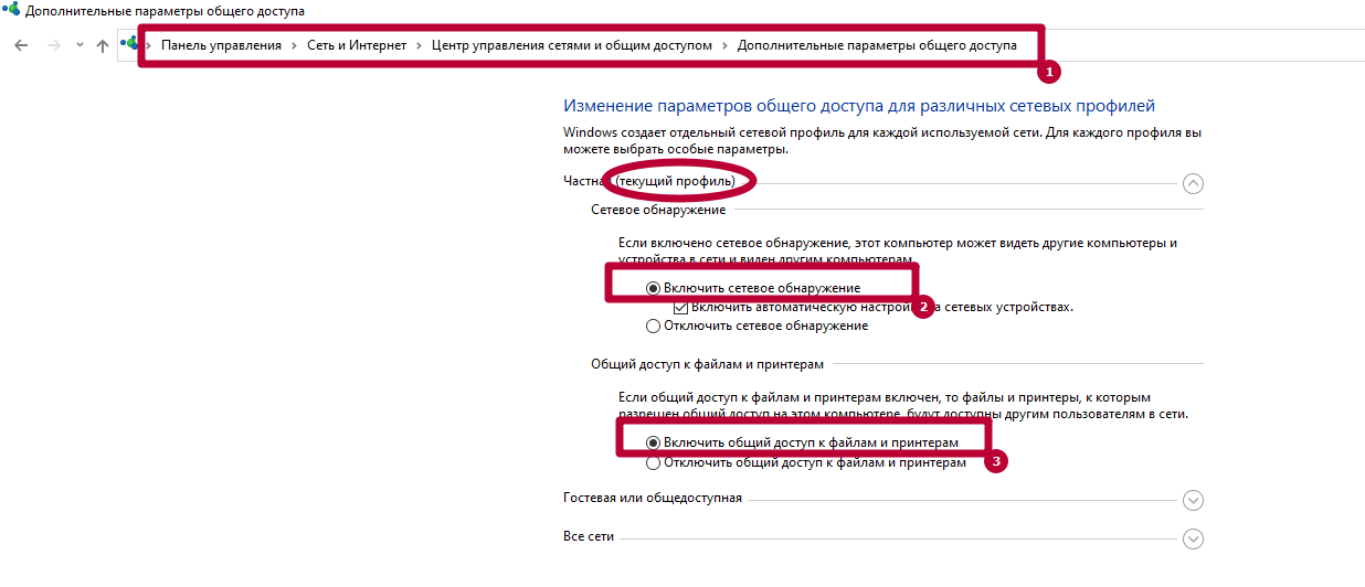 Windows 10
Убедитесь, что на МФУ включены протоколы FTP и SMB. Это можно сделать через интерфейс Command Center. Отправьте оригинал документа, выбрав направление обмена данными.
Укажите имя компьютера и название папки, открытой для общего доступа. Пропишите актуальные данные авторизации для входа на ПК. После проверки подтвердите операцию, нажав «Старт».
Другие ошибки и их решение
На МФУ также могут появиться похожие сбои. Наиболее распространенные – 1103 и 1105.
Появляется при передаче через SMB либо FTP сервер из-за неправильно указанного имени пользователя либо пароля. Также появляется при отсутствии прав доступа к сетевой папке.
Возникает, если в Command Center на Kyocera не включена функция передачи через FTP, SMB или SMTP сервер. В этом случае необходимо задать значение в настройках принтера.
Источник
Устранение ошибки передачи – Инструкция по эксплуатации Kyocera Ecosys m2040dn
Страница 367
Устранение неисправностей > Устранение неисправностей
Устранение ошибки передачи
Меры по устранению
Не удалось отправить
электронную почту.
Проверьте правильность имени хоста SMTP
сервера в Command Center RX.
Не удалось отправить через
FTP.
Проверьте имя хоста FTP.
Не удалось отправить через
SMB.
Проверьте имя хоста SMB.
Не удалось отправить через
SMB.
Проверьте настройки SMB:
•
имя пользователя и пароль при входе.
Если отправитель является пользователем
домена, укажите имя домена:
•
Не удалось отправить
электронную почту.
Проверьте следующее на Command Center RX:
•
имя пользователя и пароль для сервера SMTP;
имя пользователя и пароль для сервера POP3;
предел размера сообщения эл. почты.
Не удалось отправить через
FTP.
Проверьте настройки FTP-сервера:
•
имя пользователя и пароль при входе.
Если отправитель является пользователем
домена, укажите имя домена:
право доступа получателя к папке.
Не удалось отправить через
SMB.
Проверьте настройки SMB:
•
имя пользователя и пароль при входе.
Если отправитель является пользователем
домена, укажите имя домена:
право доступа получателя к папке.
Не удалось отправить через
FTP.
Проверьте настройки FTP-сервера:
•
право доступа получателя к папке.
Не удалось отправить
электронную почту.
Проверьте адрес электронной почты.
Если адрес отклонен доменом, отправка
электронного письма невозможна.
Источник
Kyocera ошибка соединения 0x2101 smtp
Для сканирования и отправки документов по e-mail для МФУ М2835dw необходимо не только наполнить адресную книгу, но и настроить отправку почты по e-mail. Для реализации этой возможности нужно настроить параметры почтовых протоколов, благодаря которым почта будет отправляться на выбранные адреса.
Для настройки отправки почты придется пройтись по меню аппарата, перепрыгивая с одного окна на другое. Над удобством меню, как и над логикой управления инженерам kyocera явно стоит поработать. Перед настройкой необходимо создать пользователя на любом почтовом сервере. В данном случае был создан пользователь Адрес электронной почты защищен от спам-ботов. Для просмотра адреса в вашем браузере должен быть включен Javascript. (на почтовом сервере yandex).
1. Открываем веб-панель МФУ Ecosys Kyocera M2835dw, набираем логин, пароль (по умолчанию Admin — Admin).
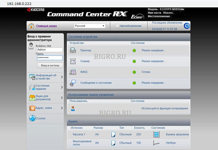
2. Далее переходим «Настройки функций» — «Электронная почта«.
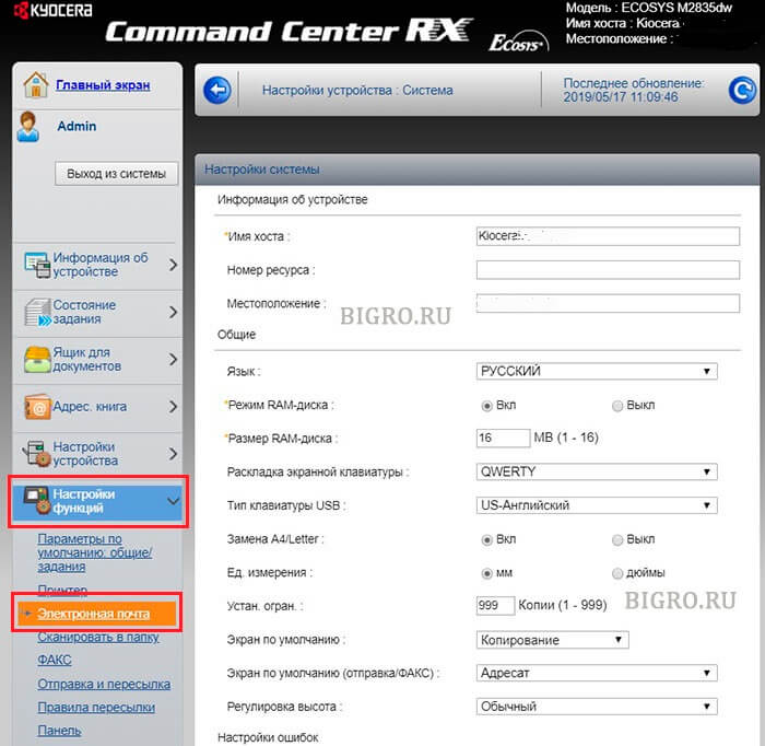
3. В открывшемся окне заполняем:
Имя сервера SMTP: 213.180.193.38
Имя севера SMTP (сервер исходящей почты) зависит от используемого почтового сервера. В данном случае IP-адрес почтового сервера по протоколу smtp 213.180.193.38 (smtp.yandex.ru). Посмотреть настройки основных почтовых серверов можно ЗДЕСЬ.
Имя сервера SMTP лучше задать по имени (например, для Yandex — smtp.yandex.ru), но если в сети не работает DNS, то МФУ не будет понимать, что такое smtp.yandex.ru. Проверить можно набрав в командной строке: ping smtp.yandex.ru. Если будет ответ от сервера (пройдут пинги), то можно прописать имя почтового сервера по протоколу smtp, если пинги не пройдут, тогда указываем IP-адрес.
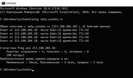
Номер порта smtp: 465.
В данном случае используется шифрование, данный порт используется на почтовом сервере Yandex по протоколу SMTP.
Протокол аутентификации: Вкл.
Аутенфицировать как: Пользователь 1 POP3.
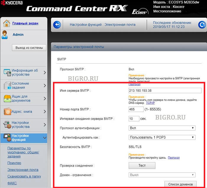
4. В секции «Настройки отправки электронной почты» настраиваем:
Адрес отправителя: Адрес электронной почты защищен от спам-ботов. Для просмотра адреса в вашем браузере должен быть включен Javascript. .
Адрес отправителя — созданный почтовый аккаунт.
Нажимаем «Передать» для сохранения настроек. Далее в секции «POP3» нажимаем кнопку «Параметры» («Настройки пользователя POP3«).
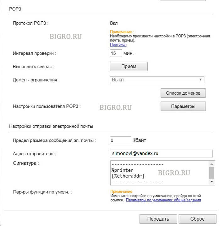
5. В окне «Настройки пользователя POP3«:
Профиль пользователя 1: Вкл.
Адрес электронной почты: Адрес электронной почты защищен от спам-ботов. Для просмотра адреса в вашем браузере должен быть включен Javascript. .
Адрес электронной почты — созданный почтовый аккаунт.
Имя сервера POP3: 213.180.204.212
Имя севера POP3 (сервер входящей почты) зависит от используемого почтового сервера. В данном случае IP-адрес почтового сервера по протоколу pop3 213.180.204.212 (pop.yandex.ru). Посмотреть настройки основных почтовых серверов можно ЗДЕСЬ.
Имя сервера POP3 лучше задать по имени (например, для Yandex — pop.yandex.ru), но если в сети не работает DNS, то МФУ не будет понимать, что такое pop.yandex.ru. Проверить можно набрав в командной строке: ping pop.yandex.ru. Если будет ответ от сервера (пройдут пинги), то можно прописать имя почтового сервера по протоколу POP3, если пинги не пройдут, тогда указываем IP-адрес.
Номер порта POP3: 995.
В данном случае используется шифрование, данный порт используется на почтовом сервере Yandex по протоколу POP3.
Имя пользователя для регистрации Адрес электронной почты защищен от спам-ботов. Для просмотра адреса в вашем браузере должен быть включен Javascript. .
Имя пользователя для регистрации — созданный почтовый аккаунт.
Нажимаем «Передать» для сохранения настроек. Далее нажимаем «Протокол» (Примечание: Произведите настройку здесь).
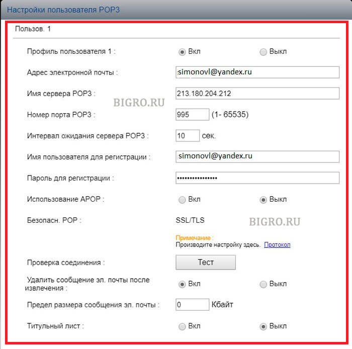
6. В новом окне настраиваем:
POP3 (прием эл. почты): Вкл.
Безоп. POP3 (Пользов. 1): SSL/TLS.
SMTP (передача эл. почты): Вкл.
Безопасность SMTP: SSL/TLS.
Нажимаем «Передать» для сохранения настроек. Далее нажимаем «Защита сети» (Примечание: Для использования этих настроек включите SSL).
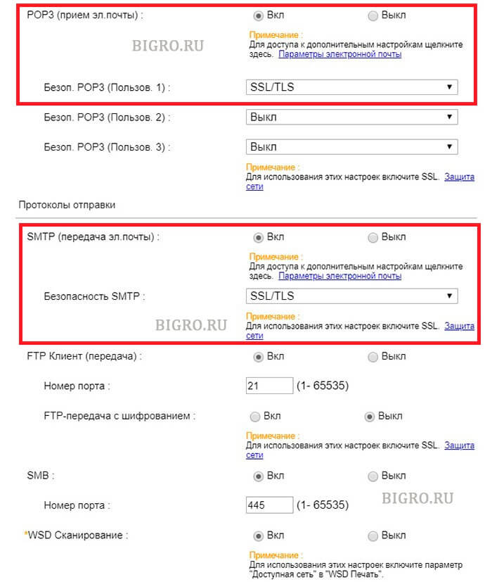
7. В открывшемся окне «Настройки сетевой безопасности» включаем SSL:
SSL: Вкл.
Нажимаем «Передать» для сохранения настроек.
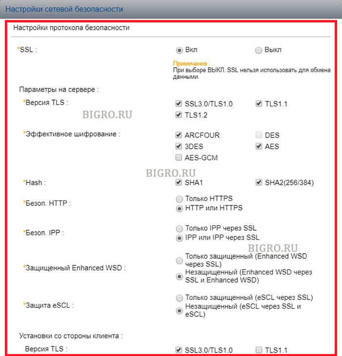
7. Далее переходим в «Настройки электронной почты» (Настройки функций — Электронная почта), в секции SMTP нажимаем кнопку «Тест«. При успешном соединении появится сообщение «Соединение ОК». Это значит, что настройки произведены правильно. Теперь можно сканировать документы и передавать по электронной почте выбранным в адресной книге адресатам.
Источник
Thread: KM-5050 Scan to SMB Error 2101
Thread Tools
Display
KM-5050 Scan to SMB Error 2101
Hello everyone,
I have a KM-5050 with firmware version 2GR_2000.014.028 2007.11.02,
Print works ok.
Trying to hook it up to scan to a folder (via SMB) on Windows Server 2008 R2 Data Center.
Scan to email is also working. I have tried using the hostname and IP address. The username and password is also a domain admin account.
For testing, when hooking it up to an individual laptop, the scan to SMB folder works ok.
Is there any suggestion anyone may know about to get this working?
Is my firmware the culprit?
Thanks in advance for your help.
Claudio
Re: KM-5050 Scan to SMB Error 2101
I remember seeing something like this before. When you put in the username info you need to add the domain info as well. I for the life can’t remember where I saw this but I’ll look around in some stuff I have around and see if I can find it.
update found the info in the Kyocera Scan to SMB(PC) set up guide. check this
Check the information in “domain nameuser name” format for logging onto Windows.
1 Press the Ctrl-Alt-Delete key combination on the
keyboard.
2 Check the Logon Information that appears on the
Windows Security window. In the sample window
below, “ABCDNETjames.smith” corresponds to
“domain nameuser name”.
(Example: ABCDNET james.smith)
Service Manager 1,000+ Posts 

 Join Date Feb 2010 Posts 1,910 Rep Power 71
I think 2101 implies a firewall/anti virus issue
Master Of The Obvious 10,000+ Posts
 Join Date Jul 2007 Location Lapeer, Michigan Posts 21,181 Rep Power 422
Re: KM-5050 Scan to SMB Error 2101
You can get 2101 for a hostname IP issue, or a login/password issue. Either one.
For the sake of diagnosis, I’d suggest creating a new user with a new known password, and new admin properties. Most times it’s login/password related, even if you can log in to the PC/server with this info sometimes it won’t work from the MFP. Many times this has resolved 2101 errors. =^..^=
Re: KM-5050 Scan to SMB Error 2101
Totally agree with this solution, I have a story
Call out to the Customer, 2 local Meath GAA players (Gaelic football) for top tray malfunction on a Kyocera model /Utax 1625. I cleaned the machine located the problem as the try paper size guide was broke etc. I taught I was done, when the Customer told me that the machine won’t print or scan.
I re-installed drivers etc., put in all the scan data and tried to scan ERROR 2101 kept coming up. So out to the car and plugged in the laptop and print and scan function working 100%. I asked the Customer any changes recently and they said the router so I inspect and its fine. I then check the only Pc connected to the machine and give it a good going over. I find the McAfee anti-virus software and disable it and hooray I can print but no scan. I ask the Customer was the anti-virus updated and he said no, shortly after my SM rang because I was there 1.5 hours I explained what happened and he told me to just get going.
I tell the Customer that I must go but would be back with the rtf parts that my SM has been on and that they should have logged the call regarding the print and scan, as I was only into my 2nd year and that call would require a more exp Tech and that if they wanted to print they must either disable or change their settings in the Anti-virus to allow printing. I was not long gone when the Customer called the Office giving out saying I was hopeless etc. and yes my SM called the Customer and asked was the Anti-Virus changed, when he finished that call he gave me the hairdryer treatment. I told him that when I finished the call they wanted me to look at the printing etc., I told him it was the Anti-Virus blocking the printing and he still fumed and sent my Supervisor there. The Supervisor rang me and I told him the story and he came back with a report that the Router was faulty and told the Customer to change it.
It was less than a week and the Customer was raging, the router did not work. The call was logged and the SM sent out his golden boy, the Polish Master who was a lazy git TBH, I have to admit he was there for 3 hours and solved the problem. It was the anti-virus, and yes they had recently got an IT guy in to install it. I was never thanked for attempting the repair but the Customer was charged for the call out and not telling anyone about the change. SUCKER
Источник
Below is a long list of Kyocera error codes. Some Kyocera printers can be reset by turning the machine power switch off and back on while some others activate “partial operation control” disabling the defective part/area of the machine (paper feed cassette, stapler, document processor etc). If a specific unit is not working, perform U906 after taking measures against the cause of trouble to reactivate the unit.