![]()
Hello,
I am trying to use newest duet firmware on my duet with duex, I have two extruders on the machine, I see right temperature, but when I try extrude material or heat the hottend I had this message:
Attempting to extrude with no tool selected
or
Setting temperature: no tool selected
And extruding or heating doesnt work at all, no move, no heating.
You probably need to ask Tony at Think3DPrint3D, he’s got the most experience with the Duet expansion board.
Ian
RepRapPro tech support
Had same issue. Change extrude number, instead of counting from zero start counting from one. No idea why they changed this but that s what the problem was (at least on my ormerod  )
)
Hi hj14,
If you are generating the model using slic3r, then the problem is that slic3r assumes the tools are numbered T0 and T1, but the Duet firmware assumes T1 and T2.
Here are two solutions:
1. In my blog entry at [miscsolutions.wordpress.com], towards the end I provide a script to edit the files generated by slic3r to change the tool numbering. It also changes the M109 commands with T parameters generated by slic3r to the G10 commands recognized by the Duet firmware.
2. If you download my 0.78f-dc42 firmware (see [forums.reprap.org]) and add the command M563 S1 to your slic3r custom start gcode, then it will renumber the tools for you, and it also supports the T parameter in the M109 command.
You might also like to try the web interface at [github.com] in preferance to the USB port, it makes the Duet much easier to use.
Large delta printer [miscsolutions.wordpress.com], E3D tool changer, Robotdigg SCARA printer, Crane Quad and Ormerod
Disclosure: I design Duet electronics and work on RepRapFirmware, [duet3d.com].
First off a big thanks to dc42 for all the knowledge on the Duet. I’ve been converting my Prusa i3 and for the most part have been living on your forum and blog posts.
Everything’s running well except the Slic3r situation you denote… I tried adding the M563 S1 command but it doesn’t seem to fix the issue. Would you be able to point me towards where I need to look to make sure the g code is selecting the right tool etc?
In the web UI I see the extruder listed as T0 (by default), in the trouble-causing g-code I do not see any tool selection code T0 for example… although T0 does run at the end of my config.g file
I’m sure I’ll track this down by trial and error but thought I would ask the question.
Thanks again!
Since firmware version 1.04, the default has been to number the tools T0 and T1, which is what slic3r expects. This requires you to set up your config.g file so that the M563 commands number the tools as 0 and 1. If they show as T0 and T1 in the web interface, it sounds as though you have already done this. So you do not need the M563 S1 command in the start gcode and you must remove it.
Be aware that after you complete or cancel8 a print, both tools will be deselected, so you need to send T0 again before printing. So I recommend you put T0 at the beginning of your slic3r start gcode.
HTH David
Large delta printer [miscsolutions.wordpress.com], E3D tool changer, Robotdigg SCARA printer, Crane Quad and Ormerod
Disclosure: I design Duet electronics and work on RepRapFirmware, [duet3d.com].
An explanation of how tools are configured and enabled is here: [reprappro.com]
Ian
RepRapPro
ereur
Edited 1 time(s). Last edit at 03/11/2020 12:57AM by neetspeed.
Recommend Projects
-

React
A declarative, efficient, and flexible JavaScript library for building user interfaces.
-
Vue.js
🖖 Vue.js is a progressive, incrementally-adoptable JavaScript framework for building UI on the web.
-
Typescript
TypeScript is a superset of JavaScript that compiles to clean JavaScript output.
-
TensorFlow
An Open Source Machine Learning Framework for Everyone
-
Django
The Web framework for perfectionists with deadlines.
-
Laravel
A PHP framework for web artisans
-
D3
Bring data to life with SVG, Canvas and HTML. 📊📈🎉
Recommend Topics
-
javascript
JavaScript (JS) is a lightweight interpreted programming language with first-class functions.
-
web
Some thing interesting about web. New door for the world.
-
server
A server is a program made to process requests and deliver data to clients.
-
Machine learning
Machine learning is a way of modeling and interpreting data that allows a piece of software to respond intelligently.
-
Visualization
Some thing interesting about visualization, use data art
-
Game
Some thing interesting about game, make everyone happy.
Recommend Org
-
Facebook
We are working to build community through open source technology. NB: members must have two-factor auth.
-
Microsoft
Open source projects and samples from Microsoft.
-
Google
Google ❤️ Open Source for everyone.
-
Alibaba
Alibaba Open Source for everyone
-
D3
Data-Driven Documents codes.
-
Tencent
China tencent open source team.
[Windows] XBox One controller failed to map left and right trigger correctly
I already tried with suggested tools and both Steam and SDL2 Gamepad Tool recognize my Xbox gamepad correctly included the left and right triggers. This was the reason due to I put the issue here, I though the problem was not related to SDL2 but the way antmicro read the inputs.
If this is not related to AntMicro can you point me out the right way to solve?
[Windows] XBox One controller failed to map left and right trigger correctly
Is there an existing issue for this?
- [X] I searched the existing issues and did not find anything similar.
Current Behavior
I have an XBox One controller (1708) connected using wireless adapter.
When I map the controller the left and right triggers have weird behaviour:
- the left one values changes but the range is very limited (from Axis 8: 32767 to Axis 8: 32257)
- the right one seems not recognized at all
Expected Behavior
Value changing for both left and right triggers when pressed.
I tried with Windows Game Device and both axis works correctly. I also tried with XPadder and it works correctly too.
Steps To Reproduce
- connect an XBox Controller
- open AntMicroX and go to Map Controller
- go to Left Trigger and press the trigger on controller
Environment
Program Version 3.3.2
Compiled from packaging: GitHub Portable Windows Release
Built Against SDL 2.0.20
Running with SDL 2.0.20
Using Qt 5.15.2
Using Event Handler: SendInput
Host OS: windows Version: 7sp1 Architecture: x86_64
Anything else?
No response
[Request] Add option to specify infill/perimeter overlap for bridges
I have this problem too: in some cases the bridge does not connect correctly to walls due to poor overlapping amount.
I think it will be very useful to have a parameter to set this
attempting to extrude with no tool selected
attempting to extrude with no tool selected
June 02, 2014 01:36PM Registered: 8 years ago
Posts: 2
I am trying to use newest duet firmware on my duet with duex, I have two extruders on the machine, I see right temperature, but when I try extrude material or heat the hottend I had this message:
Attempting to extrude with no tool selected
or
Setting temperature: no tool selected
And extruding or heating doesnt work at all, no move, no heating.
Re: attempting to extrude with no tool selected
June 03, 2014 04:29PM Registered: 11 years ago
Posts: 1,611
You probably need to ask Tony at Think3DPrint3D, he’s got the most experience with the Duet expansion board.
Ian
RepRapPro tech support
Re: attempting to extrude with no tool selected
July 30, 2014 03:37PM Registered: 8 years ago
Posts: 40
Re: attempting to extrude with no tool selected
July 30, 2014 04:03PM Registered: 9 years ago
Posts: 14,634
If you are generating the model using slic3r, then the problem is that slic3r assumes the tools are numbered T0 and T1, but the Duet firmware assumes T1 and T2.
Here are two solutions:
1. In my blog entry at [miscsolutions.wordpress.com], towards the end I provide a script to edit the files generated by slic3r to change the tool numbering. It also changes the M109 commands with T parameters generated by slic3r to the G10 commands recognized by the Duet firmware.
2. If you download my 0.78f-dc42 firmware (see [forums.reprap.org]) and add the command M563 S1 to your slic3r custom start gcode, then it will renumber the tools for you, and it also supports the T parameter in the M109 command.
You might also like to try the web interface at [github.com] in preferance to the USB port, it makes the Duet much easier to use.
Large delta printer [miscsolutions.wordpress.com], E3D tool changer, Robotdigg SCARA printer, Crane Quad and Ormerod
Disclosure: I design Duet electronics and work on RepRapFirmware, [duet3d.com].
Re: attempting to extrude with no tool selected
July 11, 2015 12:07PM Registered: 8 years ago
Posts: 101
First off a big thanks to dc42 for all the knowledge on the Duet. I’ve been converting my Prusa i3 and for the most part have been living on your forum and blog posts.
Everything’s running well except the Slic3r situation you denote. I tried adding the M563 S1 command but it doesn’t seem to fix the issue. Would you be able to point me towards where I need to look to make sure the g code is selecting the right tool etc?
In the web UI I see the extruder listed as T0 (by default), in the trouble-causing g-code I do not see any tool selection code T0 for example. although T0 does run at the end of my config.g file
I’m sure I’ll track this down by trial and error but thought I would ask the question.
Re: attempting to extrude with no tool selected
July 11, 2015 02:37PM Registered: 9 years ago
Posts: 14,634
Since firmware version 1.04, the default has been to number the tools T0 and T1, which is what slic3r expects. This requires you to set up your config.g file so that the M563 commands number the tools as 0 and 1. If they show as T0 and T1 in the web interface, it sounds as though you have already done this. So you do not need the M563 S1 command in the start gcode and you must remove it.
Be aware that after you complete or cancel8 a print, both tools will be deselected, so you need to send T0 again before printing. So I recommend you put T0 at the beginning of your slic3r start gcode.
Large delta printer [miscsolutions.wordpress.com], E3D tool changer, Robotdigg SCARA printer, Crane Quad and Ormerod
Disclosure: I design Duet electronics and work on RepRapFirmware, [duet3d.com].
Re: attempting to extrude with no tool selected
July 13, 2015 07:52AM Registered: 11 years ago
Posts: 1,611
An explanation of how tools are configured and enabled is here: [reprappro.com]
idex configuration problem
March 11, 2020 12:16AM Registered: 2 years ago
Posts: 3
Edited 1 time(s). Last edit at 03/11/2020 12:57AM by neetspeed.
Источник
Error attempting to extrude with no tool selected
![]()
Hello dear community,
Excuse me for my english . it’s Google Translate. 
I have a little problem with the following error message.
«Error: Attempting to extrude with no tool selected.«
When I start a print job, the print bed is picked up as desired and then the hotend, then the print head moves into the print bed center and takes a reading with the BLTouch and then moves outside of the print bed near the home position and extrudes slightly Filament to fill the nozzle.
Exactly at this moment, the error message appears and no filament is extruded, but he starts directly to print.
But if I heat up the print bed and the nozzle to the desired temperature and then start the print job, then everything works as desired and there is no error message.
I have tried it with different firmware versions, but the error happens with each version.
Currently I use the 2.02 . but will update to the latest version again.
Here is the content of my config.g file .
—————- Config.g Start —————-
; Configuration file for Duet WiFi (firmware version 2.03)
; executed by the firmware on start-up
;
; generated by RepRapFirmware Configuration Tool v2.0.4 on Thu Oct 03 2019 18:54:38 GMT+0200 (Mitteleuropäische Sommerzeit)
; General preferences
G90 ; send absolute coordinates.
M83 ; . but relative extruder moves
M550 P»A5X» ; printer name
; Network
M552 S1 ; enable network
M586 P0 S1 ; enable HTTP
M586 P1 S0 ; disable FTP
M586 P2 S0 ; disable Telnet
; Drives
M569 P0 S0 F1 ; physical drive 0 goes backwards — x-achse (TOFF 1)
M569 P1 S1 F1 ; physical drive 1 goes forwards — y-achse (TOFF 1)
M569 P2 S0 F1 ; physical drive 2 goes backwards — z-achse links (TOFF 1)
M569 P3 S0 F1 ; physical drive 3 goes backwards — z-achse rechts (TOFF 1)
M569 P4 S0 F1 ; physical drive 4 goes backwards — extruder (TOFF 1)
M564 H0 ; erlaubt das bewegen der achsen ohne referenzierung
; Stepper und Geometrie
M584 X0 Y1 Z2:3 U3 E4 P3 ; dual z — kombiniert die beiden z achsen
M350 X16 Y16 Z16 U16 E32 I1 ; microstepping und interpolation
M92 X79.953 Y79.973 Z400.000 U400.000 E805.700 ; set steps per mm
M566 X900.00 Y900.00 Z12.00 U12.00 E120.00 ; set maximum instantaneous speed changes (mm/min) jerk
M203 X20000.00 Y20000.00 Z1000.00 U1000.00 E1200.00 ; set maximum speeds (mm/min)
M201 X900.00 Y900.00 Z20.00 U20.00 E250.00 ; set accelerations (mm/s^2)
M906 X900 Y900 Z1200 U1200 E900 I30 ; set motor currents (mA) and motor idle factor in per cent
M84 S30 ; Set idle timeout
; Axis Limits
M208 X-10.00 Y-25.00 Z0 U0 S1 ; set axis minima
M208 X330 Y330 Z360 U360 S0 ; set axis maxima
; Endstops
M574 X1 Y1 S1 ; set active high endstops (mechanic)
M574 Z1 U1 S0 ; set active low endstops (hall sensor)
; Z-Probe (BLTouch V3.0 produced since 5. April 2019)
M557 X35:295 Y35:295 S65 ; definierter messbereich / abstand (hier sind es 20mm)
M307 H7 A-1 C-1 D-1 ; Aktivierung des PWM5-Anschluss für den BLTouch
M558 P9 H3 F120 T10000 A7 S0.017 R0.2 B1 ; Sondeneinrichtung Schritt 1 (A5 S0.015 R0.2 B1)
G31 P25 X-29.50 Y0.50 Z1.330 ; Sondeneinrichtung Schritt 2
M280 P7 S160 ; BLTouch Alarm löschen (falls vorhanden)
; Heaters
M307 H0 B0 S1 ; disable bang-bang mode for the bed heater and set PWM limit
M305 P0 T100000 B3950 R4700 ; set thermistor + ADC parameters for heater 0
M143 H0 S110 ; set temperature limit for heater 0 to 110C
M305 P1 T100000 B4725 C7.060000e-8 R4700 ; set thermistor + ADC parameters for heater 1
M143 H1 S280 ; set temperature limit for heater 1 to 280C
; Fans
M106 P0 I0 F500 C «Bauteile» ; set fan 0 value, PWM signal inversion and frequency. Thermostatic control is turned off — bauteile fan
M106 P1 S1 I0 F500 H1 T45 C «Hotend» ; set fan 1 value, PWM signal inversion and frequency. Thermostatic control is turned on — hotend e3D V6 fan
; Tools
M563 P0 D0 H1 F0: 1 ; definiere werkzeug 0 — (testweise luefter 1 entfernt (F0: 1))
G10 P0 X0 Y0 Z0 ; set tool 0 axis offsets
G10 P0 R0 S0 ; set initial tool 0 active and standby temperatures to 0C
; Custom settings are not defined
Thank you for your time and help.
P.S. .:
I am only since 2 weeks owner of the Duet Wifi version 1.04C
So everything is still new and I still have a lot to learn.
But it will be !
A great piece of hardware .
DDA5X. 0.9° Stepper. Linearrails. Duet 2 Wifi. PT100 Board. Duet IR-Probe. Dyze Pro Kit up to 500°C.. etc
Thingiverse
Источник
Error attempting to extrude with no tool selected
![]()
Hello everyone after updating to 3.2 every time a part prints i have an error and the filament stopped coming out and printing continues without filament any idea?
Thank you all
M0 H1
Error: Attempting to extrude with no tool selected.
Error: Attempting to extrude with no tool selected.
config.g
![]()
Please post your config.g and an example print (or at least the first layer of an example print)
![]()
Sounds like you don’t have a tool selected at the start of a print.
Usually you’d add a T0 to the end of config.g and/or to the slicer start gcode.
![]()
Can you post an example gcode file?
Also the results of M122 and M98 P»config.g» please.
![]()
It’s done with all the gcode files and all the slices
![]()
![]()
M98 P «config.g»
Warning: Macro file «config.g» not found
![]()
No space between the P and «
![]()
M98 P»config.g»
HTTP is enabled on port 80
FTP is disabled
TELNET is disabled
Error: in file macro line 30 column 13: M591: string expected
Error: Invalid extruder number ‘1’
Warning: Macro file config-override.g not found
![]()
; Filament sensor M591 D0 P1 C3 S1 ; Set Filament sensor Simple type (High) for extruder drive 0, connected to endstop input 3 (E0
For the first error with the sensor, you need to provide the actual pin name instead of C3
How do you have it connected? It should be C»e0stop» if you were using the e0 endstop pin for example.
M572 D1 S0.275 ; Set bowden extruder elasticity compensation for E1
For the second error, you have two extruders configured for pressure advance, but you only have a single extruder defined. So remove that entry entirely.
It would still be useful to see an example gcode file so we can see what is happening at the start of a print. If the file is too large to share, you can copy and paste the first 50 lines or so, or host it on dropbox or something.
Источник
Error attempting to extrude with no tool selected
![]()
hello everyone every time a part prints my filament stops outputting and i have an error but the printer keeps printing
thank you 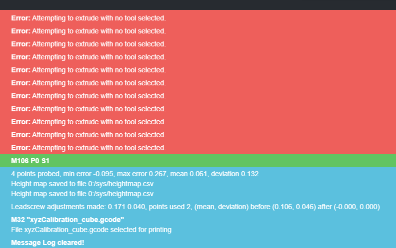 advance
![]()
Do you have a tool selection in your code?
i.e
T0 in your config.g or your start.g code?
![]()
M80 ; Turns on the ATX power supply
G90 ; Send absolute coordinates.
M83 ; . but relative extruder moves
M550 P»sgk008″ ; set printer name
; Network
M552 S1 ; enable network
M586 P0 S1 ; enable HTTP
M586 P1 S0 ; disable FTP
M586 P2 S0 ; disable Telnet
M669 K1 ; select CoreXY mode
; Endstops
M574 X1 S1 P»xstop» ; configure active-high endstop for low end on X via pin xstop
M574 Y2 S1 P»ystop» ; configure active-high endstop for high end on Y via pin ystop
M574 Z1 S2 ; configure Z-probe endstop for low end on Z
M575 P1 S1 B57600 ; Set things up for the PanelDue
; Filament sensor
M591 D0 P1 C»e0stop» S1 ; Set Filament sensor Simple type (High) for extruder drive 0, connected to endstop input 3 (E0
; Drives
M569 P0 S0 ; Drive 0 goes backwards blv: its was S1
M569 P1 S0 ; Drive 1 goes backwards blv: its was S1
M569 P2 S0 ; Drive 2 goes forwards
M569 P3 S1 ; Drive 3 goes backwards WAS 0
M569 P4 S0 ; Drive 4 goes forwards
M584 X0 Y1 Z2:4 E3 ; set drive mapping
M350 X16 Y16 Z16 E16 I1 ; Configure microstepping with interpolation
M92 X200 Y200 Z400 E415.178 ; Set steps per mm for Bondtech.
M566 X600 Y600 Z1000 E200 ; Set maximum instantaneous speed changes (Jerk) (mm/min)
M203 X20000 Y20000 Z600 E2000 ; Set maximum speeds (mm/min)
M201 X1000 Y1000 Z100 E5000 ; Set accelerations (mm/s^2)
M906 X1000 Y1000 Z1000 E1000 I30 ; Set motor currents (mA) and motor idle factor in per cent
M84 S30 ; Set idle timeout
; Axis Limits
M208 X-23 Y0 Z0 S1 ; Set axis minima
M208 X320 Y321 Z350 S0 ; Set axis maxima
M558 P1 C»^zprobe.in» H5 F200 T9000 I0 R0.5 ; Set Z probe type mini ir sensor
G31 P500 X-2 Y-16.4 Z0.310 ; Set Z probe trigger value, offset and trigger height
M557 X20:270 Y20:270 S240 ; Define mesh grid
; Heaters
M307 H0 R0.277 C337.2 D9.55 S1.00 V23.7 ; Set PID for heated bed values
M307 H1 R2.105 C132.8 D9.06 S1.00 V23.6 ; Set PID for hotend values
M308 S0 P»bedtemp» Y»thermistor» A»Bed» T100000 B4725 C0.0000000706 R4700 ; configure sensor 0 as thermistor on pin bedtemp
M950 H0 C»bedheat» T0 ; create bed heater output on bedheat and map it to sensor 0
M140 H0 ; map heated bed to heater 0
M143 H0 S120 ; set temperature limit for heater 0 to 120C
M308 S1 P»e0temp» Y»thermistor» A»Hotend» T100000 B4725 C0.0000000706 R4700 ; configure sensor 1 as thermistor on pin e0temp
M950 H1 C»e0heat» T1 ; create nozzle heater output on e0heat and map it to sensor 1
M143 H1 S260 ; set temperature limit for heater 0 to 260C
M308 S2 P»mcu-temp» Y»mcu-temp» A»Duet Board» ; Configure MCU sensor
; Tools
M563 P0 S»T0″ D0 H1 F1 ; Define tool 0
G10 P0 X0 Y0 Z0 ; Set tool 0 axis offsets
G10 P0 R0 S0 ; Set initial tool 0 active and standby temperatures to 0C
; Access point is configured manually via M587 by the user
;M586 P0 S1 ; Enable HTTP
;M586 P1 S1 ; Enable FTP
;M586 P2 S1 ; Enable Telnet
;Hot End fan tool
M950 F1 C»fan1″ Q500 ; create fan 1 on pin fan1 and set its frequency
M106 P1 C»HE Fan» S1 H1 T45 ; set fan 1 value. Thermostatic control is turned on 100% at 45deg
;Tool Fan/ Layer Fan
M950 F0 C»fan0″ Q500 ; create fan 0 on pin fan0 and set its frequency
M106 P0 S1 H-1 ; set fan 0 value. Thermostatic control is turned off
;MB cooling fan layer
M950 F2 C»fan2″ Q500 ; create fan 2 on pin fan2 and set its frequency
M106 P2 C»MB Fan» S1 H2 T35:55 ; set fan 2 value. Thermostatic control is turned on Temp Range of 35 — 55 deg
; Custom settings
M572 D0 S0.275 ; Set bowden extruder elasticity compensation for E0
M572 D1 S0.275 ; Set bowden extruder elasticity compensation for E1
M207 S4.0 F2400 Z0.075 ; Set firmware retraction parameters
; Scanner support (debug)
;M750
; Set up DHT sensor on channels 101-102
;M305 P101 X405 S»DHT temperature» T11
;M305 P102 X455 S»DHT humidity [%]» T11
; Automatic power saving
M911 S21 R22 P»M913 X0 Y0 G91 M83 G1 Z3 E-5 F1000″ ; Set voltage thresholds and actions to run on power loss
; Custom settings are not configured
M564 H0 ; Let the Jog buttons work blv: added to allow jog buttons
; Miscellaneous
M501 ; load saved parameters from non-volatile memory
T0 ; select first tool
Источник