- See the following to resolve the error.
■The register mark detection function is malfunctioning.
Check to see if the following table of settings made in either FineCut or RasterLink6
is equivalent to the settings in MENU -> CUTTING -> REGISTER MARK DETECTION.
See 『Operation Manual』-> [Chapter 4 Cutting Function]
-> [Cut Out Data with Registration Mark] for the details.
Click here to see the CJV150 Operation Manual.
Click here to see the CJV300 Operation Manual.
■Have used register marks created in design software
It’s not capable of reading register marks created in design software such as
Adobe Illustrator. Create your register marks with FineCut8 or RasterLink6.
See 『FineCut8 Operation Manual』 -> [CHAPTER 3 Creating Register Marks]
-> [Making Register Marks] to learn about how to create register marks.
Click here to see the FineCut8 Operation manual for Adobe Illustrator.
Click here to see the FineCut8 Operation manual for CorelDRAW.
■Have used non-white colored media. The color of the register marks is not black
・Turn the color of the register marks into black.
・When using media other than the color white, then it may not read the register
marks on it.
Use the function, [Fill around the register mark]in Finecut8, then it may read the
register marks if the surrounding areas are colored in red spot color.

See 『FineCut8 Operation Manual』 -> [CHAPTER 3 Creating Register Marks]
-> [Making Register Marks] to learn about how to create register marks.
Click here to see the FineCut8 Operation manual for Adobe Illustrator.
Click here to see the FineCut8 Operation manual for CorelDRAW.
*Ensure to turn ON the function, MENU -> Cutting -> TP DETECT
-> MARK FILLUP when operating the function.
Click here to see the CJV150 Operation Manual.
Click here to see the CJV300 Operation Manual.
■The printed register mark is blurred
When the register marks are blurred, the printer cannot read them. Even if it does,
the cutting operation may go off the cutting track.

■ RIP has magnified or shrank down the data contains register marks created
in FineCut8
When outputting data from the printer, never magnify or shrink the size of
the data. The register sensor will be no longer capable of reading register marks.
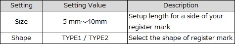
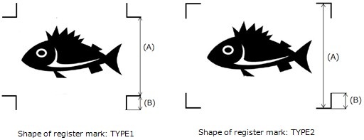
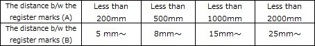
■The size of register marks is small
When the size of register marks are too small to recognize, it may not detect them
properly. Use appropriate size of register marks. The following table shows correct
size of register marks for each type; the correct size of register mark (B) against the
distance between the register marks (A).
See 『Operation manual』-> [Chapter 4 Cutting Function]
-> [Cut Out Data with Registration Mark] for the details.
Click here to see CJV150 operation manual.
Click here to see CJV300 operation manual.
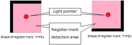
■ When detecting register marks in manual operation, the position of light pointer is
incorrect
When detecting register marks in manual operation, move the position of light pointer
over to the following register mark position.
See 『Operation manual』 -> [Chapter 4 Cutting Function]
-> [Cut Out Data with Registration Mark] for the details.
Click here to see CJV150 operation manual.
Click here to see CJV300 operation manual.
■ Some data are printed in print-free area surrounding the register marks
Note that the area surrounding register mark is print-free; never print any data on
the area. Also ensure that the area should be stain-free. The register mark sensor
may misread a stain as a register mark.

Shape of register mark: TYPE1 Click on Image to zoom

Shape of register mark: TYPE2 Click on Image to zoom
See 『Operation manual』 -> [Chapter 4 Cutting Function]
-> [Cut Out Data with Registration Mark] for the details.
Click here to see CJV150 operation manual.
Click here to see CJV300 operation manual.
■ The distance between the register marks of two separate images are too narrow
When the distance between the register marks of two separate image are too narrow,
it may not detect register marks properly.
【The case when the shape of register mark is TYPE1】
Make the distance more than twice as long as the side of the register mark and less
than 1000mm.
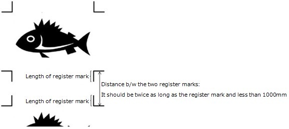
Shape of register mark: TYPE1
【The case when the shape of the register mark is type2】
Make the distance more than the side of the register mark and less than 1000mm.
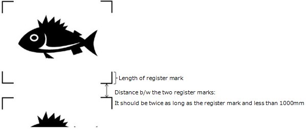
Shape of register mark: TYPE2
See 『Operation manual』 -> [Chapter 4 Cutting Function]
-> [Cut Out Data with Registration Mark] for the details.
Click here to see CJV150 operation manual.
Click here to see CJV300 operation manual.
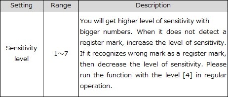
■Increase sensitivity level of the sensor
Change the printer settings on the sensitivity level at MENU -> Cutting -> TP DETECT.
See 『Operation Manual』-> [Chapter 4 Cutting Function]
-> [Cut Out Data with Registration Mark] for the details.
Click here to see the CJV150 Operation Manual.
Click here to see the CJV300 Operation Manual.
■Adjusting the position of light pointer
When it does not read register marks, the position of the register sensor and light
pointer may not match.
Go to MENU -> Cutting -> MAINTENANCE -> MARK SENSOR -> POINTER OFFSET
and adjust the position of the light pointer on the printer.
See 『Operation Manual』-> [Chapter 4 Cutting Function]
-> [Cut Out Data with Registration Mark] for the details.
Click here to see the CJV150 Operation Manual.
Click here to see the CJV300 Operation Manual.
-
Волков СВ
- Новичок

- Сообщения: 31
- Зарегистрирован: 02 авг 2012 17:00
- Последний визит: 01 окт 2020 09:10
- Изменить репутацию:
Репутация:
Голосов: 2 - Откуда: Москва

MIMAKI CG-130SR II не видит метки (ERR36 MARKdetect)
Плоттер настроен на определение по 4 меткам, TYPE2, 20мм пол года отработал без огрехов. Совет сервис службы — заново настроить (делал) протереть оптику спиртовой салфеткой (тоже делал). Не помогло.
Из корела все работает
Подскажите, была ли у кого либо сходная проблема
-
kireyev
Re: MIMAKI CG-130SR II не видит метки (ERR36 MARKdetect)
Сообщение kireyev » 12 окт 2012 11:07
Была при установке плоттера. Там где-то есть настройка в мозгах плоттера в какую сторону и на какую длину искать метку по осям X и Y.
-
Волков СВ
- Новичок
- Сообщения: 31
- Зарегистрирован: 02 авг 2012 17:00
- Последний визит: 01 окт 2020 09:10
- Изменить репутацию:
Репутация:
Голосов: 2 - Откуда: Москва
Сообщение Волков СВ » 12 окт 2012 11:55
Благодарствую посмотрим.
-
Волков СВ
- Новичок
- Сообщения: 31
- Зарегистрирован: 02 авг 2012 17:00
- Последний визит: 01 окт 2020 09:10
- Изменить репутацию:
Репутация:
Голосов: 2 - Откуда: Москва
Сообщение Волков СВ » 12 окт 2012 15:49
FUNKTIONSETUPMARK DETECTSCEW CHECK называется, выставил на 30мм, увиделось. Как оно слетело не пойму… В настройки не лазил никто.
Вернуться в «Режущие плоттеры MIMAKI»
Кто сейчас на конференции
Сейчас этот форум просматривают: нет зарегистрированных пользователей и 1 гость
Click here follow the steps to fix Mimaki Error 36-c Mark-detect and related errors.
|
|
|
|
To Fix (Mimaki Error 36-c Mark-detect) error you need to |
|
|
Step 1: |
|
|---|---|
| Download (Mimaki Error 36-c Mark-detect) Repair Tool |
|
|
Step 2: |
|
| Click the «Scan» button | |
|
Step 3: |
|
| Click ‘Fix All‘ and you’re done! | |
|
Compatibility:
Limitations: |

Mimaki Error 36-c Mark-detect Error Codes are caused in one way or another by misconfigured system files
in your windows operating system.
If you have Mimaki Error 36-c Mark-detect errors then we strongly recommend that you
Download (Mimaki Error 36-c Mark-detect) Repair Tool.
This article contains information that shows you how to fix
Mimaki Error 36-c Mark-detect
both
(manually) and (automatically) , In addition, this article will help you troubleshoot some common error messages related to Mimaki Error 36-c Mark-detect error code that you may receive.
Note:
This article was updated on 2023-02-03 and previously published under WIKI_Q210794
Contents
- 1. What is Mimaki Error 36-c Mark-detect error?
- 2. What causes Mimaki Error 36-c Mark-detect error?
- 3. How to easily fix Mimaki Error 36-c Mark-detect errors
What is Mimaki Error 36-c Mark-detect error?
The Mimaki Error 36-c Mark-detect error is the Hexadecimal format of the error caused. This is common error code format used by windows and other windows compatible software and driver vendors.
This code is used by the vendor to identify the error caused. This Mimaki Error 36-c Mark-detect error code has a numeric error number and a technical description. In some cases the error may have more parameters in Mimaki Error 36-c Mark-detect format .This additional hexadecimal code are the address of the memory locations where the instruction(s) was loaded at the time of the error.
What causes Mimaki Error 36-c Mark-detect error?
The Mimaki Error 36-c Mark-detect error may be caused by windows system files damage. The corrupted system files entries can be a real threat to the well being of your computer.
There can be many events which may have resulted in the system files errors. An incomplete installation, an incomplete uninstall, improper deletion of applications or hardware. It can also be caused if your computer is recovered from a virus or adware/spyware
attack or by an improper shutdown of the computer. All the above actives
may result in the deletion or corruption of the entries in the windows
system files. This corrupted system file will lead to the missing and wrongly
linked information and files needed for the proper working of the
application.
How to easily fix Mimaki Error 36-c Mark-detect error?
There are two (2) ways to fix Mimaki Error 36-c Mark-detect Error:
Advanced Computer User Solution (manual update):
1) Start your computer and log on as an administrator.
2) Click the Start button then select All Programs, Accessories, System Tools, and then click System Restore.
3) In the new window, select «Restore my computer to an earlier time» option and then click Next.
4) Select the most recent system restore point from the «On this list, click a restore point» list, and then click Next.
5) Click Next on the confirmation window.
6) Restarts the computer when the restoration is finished.
Novice Computer User Solution (completely automated):
1) Download (Mimaki Error 36-c Mark-detect) repair utility.

2) Install program and click Scan button.
3) Click the Fix Errors button when scan is completed.
4) Restart your computer.
How does it work?
This tool will scan and diagnose, then repairs, your PC with patent
pending technology that fix your windows operating system registry
structure.
basic features: (repairs system freezing and rebooting issues , start-up customization , browser helper object management , program removal management , live updates , windows structure repair.)
Содержание
- Error 36 C Mark Detect
- [ERROR c36 Mark detect] is displayed About cutmark FAQ .
- How to solve problem error 36 code on mimaki cg130sr3 .
- Mimaki Core Technology: Mark Detect — YouTube
- Why do I get an «Unprotected Formula» message in Excel .
- WebBrowser control error message page handling
- HP PCs — Troubleshooting HP Support Assistant (Windows 10 .
- Chapter 10 Error Detection and Correction
- Detecting and Correcting Errors — MIT
- Error using langdetect in python: «No features in text .
- c# — How to mark a method as obsolete or deprecated .
- Error 36 C Mark Detect Fixes & Solutions
- Error Messages
- Mimaki CG-130 FX ‘ERR36 MARKdetect’ *PLEASE HELP*
- High Side Design
- iSign
- ddubia
- MikePro
- High Side Design
- High Side Design
- MikePro
- ddubia
Error 36 C Mark Detect

We have collected for you the most relevant information on Error 36 C Mark Detect, as well as possible solutions to this problem. Take a look at the links provided and find the solution that works. Other people have encountered Error 36 C Mark Detect before you, so use the ready-made solutions.
[ERROR c36 Mark detect] is displayed About cutmark FAQ .
- https://mimaki.com/support/faq/cutmark/entry-58814.html
- [ERROR c36 Mark detect] is displayed See the following to resolve the error. в– The register mark detection function is malfunctioning. Check to see if the following table of settings made in either FineCut or RasterLink6
How to solve problem error 36 code on mimaki cg130sr3 .
- https://www.youtube.com/watch?v=sRGfd8nbc24
- Apr 06, 2019 · If you have trouble on print and cut small thing. May be this advice will helping.Check it out.Author: Deny hadyant
Mimaki Core Technology: Mark Detect — YouTube
- https://www.youtube.com/watch?v=xQH6QaizN7U
- Oct 21, 2016 · With Mimaki cutting devices, repeat work and long cuts are simple and accurate. With Mark Detect, each copy produced is automatically registered quickly, cre. Author: Mimaki USA, Inc.
Why do I get an «Unprotected Formula» message in Excel .
- https://support.microsoft.com/en-us/office/why-do-i-get-an-unprotected-formula-message-in-excel-412bfa2e-9242-4c34-a0e4-b7b36e28d04d
- Sometimes, you might see a green triangle in the upper-left corner of a cell that contains a formula. Find out what this means and how to prevent this in Excel 2016 for Windows.
WebBrowser control error message page handling
- https://social.msdn.microsoft.com/forums/windows/en-us/4762ca62-e2c1-4295-a60a-1e6192aa9c0d/webbrowser-control-error-message-page-handling
- Mar 25, 2011 · Please remember to click “Mark as Answer” on the post that helps you, and to click “Unmark as Answer” if a marked post does not actually answer your question. This can be beneficial to other community members reading the thread.
HP PCs — Troubleshooting HP Support Assistant (Windows 10 .
- https://support.hp.com/in-en/document/c03601631
- For Samsung Print products, enter the M/C or Model Code found on the product label. — Examples: “SL-M2020W/XAA” Include keywords along with product name. Examples: «LaserJet P1007 paper jam», «HP 280 G2 Microtower bios update» Need help finding your product name or product number? Finding your Serial Number Finding your Product Number
Chapter 10 Error Detection and Correction
plw/dccn/presentation/ch10.pdf
- 10.36. 1010—3 3 LINEAR BLOCK CODESLINEAR BLOCK CODES Almost all block codes used today belong to a subset . parity check, guaranteed to detect one single error, can alfid dd b flso find any odd number of errors. 10.45. Note A simple parity-check code can detect an odd b fdd number of errors. 10.46.
Detecting and Correcting Errors — MIT
- http://web.mit.edu/6.02/www/f2006/handouts/bits_ecc.pdf
- 6.082 Fall 2006 Detecting and Correcting Errors, Slide 16 Summary: example channel coding steps 1. Break message stream into k-bit blocks. 2. Add redundant info in the form of (n-k) parity
Error using langdetect in python: «No features in text .
- https://stackoverflow.com/questions/40783383/error-using-langdetect-in-python-no-features-in-text
- Hey I have a csv with multilingual text. All I want is a column appended with a the language detected. So I coded as below, from langdetect import detect import csv with open(‘C:\Users\dell\
c# — How to mark a method as obsolete or deprecated .
- https://stackoverflow.com/questions/1759352/how-to-mark-a-method-as-obsolete-or-deprecated
- To mark as obsolete with a warning: [Obsolete] private static void SomeMethod() You get a warning when you use it: And with IntelliSense: If you want a message: [Obsolete(«My message»)] private static void SomeMethod() Here’s the IntelliSense tool tip: Finally if you want the usage to be flagged as an error:
Error 36 C Mark Detect Fixes & Solutions
We are confident that the above descriptions of Error 36 C Mark Detect and how to fix it will be useful to you. If you have another solution to Error 36 C Mark Detect or some notes on the existing ways to solve it, then please drop us an email.
Источник
Error Messages
Check the error details in the following table corresponding to the error numbers displayed:
If the problem persists even after carrying out the corrective action corresponding to the error number, contact your local distributor, our sales office, or service center. .
Check the following points:
- Check to confirm the sheet is loaded correctly. Loading a Sheet
Check for anything that may obstruct carriage movement.
Set the sheet setting to «HEAVY».
When using roll sheet, feed to pull out the required amount of sheet in advance to provide sufficient slack.
Turn off the power and wait a while before turning the power back on. Turning Off the Power
- An overcurrent was detected in the X motor.
- An overcurrent was detected in the Y motor.
- An enabling operation was performed after sheet detection.
- Perform sheet detection.
- A problem was detected with Y origin detection (initialization).
- Turning Off the Power
- A problem was detected with the front paper sensor.
- A problem was detected with sheet width detection.
- A problem was detected with the rear paper sensor.
- An inappropriate operation was performed on the operating panel.
- The operation is invalid.
- An inappropriate operation was performed while pausing.
- Either press the [REMOTE] key to cut the data or clear the data to abort the cut.
- An error occurred in the control RAM.
- Contact your local distributor, our sales office, or service center.
- An error occurred in the system ROM.
- An error occurred in the receive buffer.
- An error occurred related to the motor.
- Received a code other than a COMMAND code.
Check the following points:
- Clear the data and resend.
Check the USB cable connection. Using a USB Cable
- Received parameter outside numerical value range
- Received an invalid device control command.
- The polygon buffer overflowed.
- Either set so as not to use polygon commands or use the MGL-lc1 command.
- The length specified by the ZX command could not be fed.
- Reset the long sheet after data has been sent from the host computer, then perform multiple sheet cutting.
- The previous sheet length could not be fed for the second sheet data onward during divided cutting.
- Load a long sheet, then switch to remote mode again.
- The command could not be automatically recognized.
- Set the command name. SET UP
- An error occurred in the communication conditions.
- Adjust the communication conditions to match the host computer. SET UP > [INTERFACE]
- An error occurred in the interface.
- Check the interface cable.
- Multiple sheet cutting was executed, but no data is saved to the receive buffer.
- Cut the data involved once more.
- The received data is too big for multiple sheet cutting.
- Change the data size.
- The sheet is too short in the feed direction.
- Use a longer sheet.
- Unable to detect register marks
Check the following points:
- Check to confirm the register marks are placed properly. Register Marks
Use an uncurled sheet.
Check the mark detection start position.
Check to confirm the register marks are black and printed on a white background.
Check to confirm the area between the register marks is clean and free of printing and images.
Check to confirm there are no errors in the mark detection settings.
If the area around the register marks is filled in, set [MARK DETECT] > [MARK FILL UP] setting to «ON».
- The register mark detection result shows that the register marks were outside the register mark reading range.
- Set the register marks within the register mark reading range. Reading Range of Register Marks
- Register mark detection was performed, but the calculated correction value is abnormal, so either the detection was erroneous or the correction value was incorrectly specified.
- Check the correction value and repeat detection.
- The calculated scale compensation value was 1.3 or more or 0.7 or less.
- Eliminate any causes of mis-detection, such as blurred printed register mark data, before repeating.
- Mis-detected due to being too close to the adjacent image.
- Ensure an appropriate distance from the adjacent image before printing again.
- The specified register mark spacing is incorrect.
- Invalid register mark spacing was specified by the command, or data was incorrectly selected. Check the data to be output.
- Images were skipped due to the printed register marks not being aligned.
- Align the data and repeat printing.
- Printed register marks were not correctly read due to problems such as blurred register marks, and the register marks for the adjacent image were read instead.
- Repeat printing, taking care to prevent blurring.
- Register mark IDs could not be detected. (Data with IDs)
Check the following points:
- Check to confirm that the paper is not curled. Check to confirm the register mark IDs are black printed on a white background. Use three pinch rollers when using thin sheets or sheets more than approximately 800 mm wide.
- The pinch rollers are not over the grit rollers.
- Reposition the pinch rollers above the grit rollers.
- Unable to detect pen height
- Turn off the power and wait a while before turning the power back on. Turning Off the Power
Check the following points:
- Make sure the pen line rubber is not worn or deformed and remains intact.
- Check to confirm nothing adheres to the pen line rubber.
- After installing the pen in a commercially available pen holder, check to confirm the installed position is correct.
CG-AR Series[Ope] | Operation Manual | FW 1.2.0 | D203577-11
© 2022 MIMAKI ENGINEERING CO., LTD.
Источник
Mimaki CG-130 FX ‘ERR36 MARKdetect’ *PLEASE HELP*
High Side Design
New Member
Hi everyone! I’m very new to the whole printing game. I’ve watched people do it, I design a lot of logos and race cars, but I’ve never printed.
I took the leap and purchased some equipment from a company and I’m trying to set it up now.
Well I’ve finally gotten my printer working, but now I’m having issues w/ the CG-130 FX plotter.
I am working with Flexi Sign 8.1 and I believe I have everything linked and working correctly. For some reason, it is not reading the contour lines and it’s giving me the ‘ERR36 Markdetect’ message. I’ve tried and tried and tried to mess with settings, clean the head, change the position of the pinch wheels, etc.
Here’s a video I posted to YouTube to watch. (don’t mind the crying baby, she’s teething and an unhappy camper). I’m in desperation mode to get this working, because I have jobs that are backed up now.
Any help would be much appreciated. Feel free to ask questions and I’ll attempt to answer with the best of my knowledge.

iSign
New Member
I’ve been using that cutter out of Flexi, for a good 8 or 9 years now, I think. It gives me grief now & then, but for the most part, just works.
As a result, I don’t have a lot of trouble shooting, or training knowledge. I just send jobs, react on automatic pilot more or less. and it works.
I want to start by asking where you actually start this process. Before I get that red light, I am closing the pinch rollers, & a process starts, whereby the cutter head traverses the material width, looking for an alignment between front two reg. marks, and then, based on my settings (a 3-point check) it goes to rear right mark & then comes to the orgin point, turning on the light.
You don’t show that, so, are you doing that?

ddubia
New Member
I’m using a CG 160 through Illustrator CS2 with Mimaki’s Fine Cut software.
I use the other type of register mark. The one that is 180° from the one you are using. Basically it forms the corners of a box around your print rather than the inverted corner if that makes sense.
You may be already be using the correct register mark for Flexi. I don’t know. Though we have Flexi and I’ve cut plenty of cut-vinyl through it I’ve never set up a print file within it.

MikePro
New Member
High Side Design
New Member
I’ve been using that cutter out of Flexi, for a good 8 or 9 years now, I think. It gives me grief now & then, but for the most part, just works.
As a result, I don’t have a lot of trouble shooting, or training knowledge. I just send jobs, react on automatic pilot more or less. and it works.
I want to start by asking where you actually start this process. Before I get that red light, I am closing the pinch rollers, & a process starts, whereby the cutter head traverses the material width, looking for an alignment between front two reg. marks, and then, based on my settings (a 3-point check) it goes to rear right mark & then comes to the orgin point, turning on the light.
You don’t show that, so, are you doing that?
Yeah, I have the pinch rollers set correctly. when I close the lever, the process begins where it reads all 3 rollers, then it reads the length (back to front). Then when it is done reading, the red light comes on and it is set to TP1 mode. I then proceed to line up the red light down in the bottom right corner (shown in the video) and then hit the ‘Enter’ button.
High Side Design
New Member
MikePro
New Member
I’ve also been known to have mark-read errors in the past, that I could not solve. could be dust on the eye of the sensor, or a glare from the material/laminate, I wish I knew. One day it just works like it should and the other day it wants to be a *****. Someday I’ll figure it out, but I don’t have the time right now.
I do have a temporary fix to keep you cutting:
1)make sure the material is loaded with the crosshairs as square as possible.
2)set the cutter’s home at the corner of the front-right mark, load a pen tool with no ink into the cutter, and send the file to cut.
3)upon hitting the remote button, it will then try to read the marks, but obviously it errors-out when it cannot read the marks.
4)hit «remote» again and again while it keeps beeping the error at you and eventually it will actually try to cut your file. its weird, but it does. at least for my onyx cut server it does.
5)the pen tool will make an impression on your print where its trying to cut
6)make note of the offset, adjust your home point, and repeat until your confident enough with the cutter’s intended cut path to put in the cutter tool.
it won’t be perfect, but it will cut. luckily for me, I always had issues cutting perfectly square so I always bleed my print as much as i can.
ddubia
New Member
I wrote the following as part of the procedure of plotting a printed job through Mimaki’s Fine Cut software out of Illustrator. However, the portion below should deal with setting up your material in the plotter regardless of which software you are using. Perhaps if you read this over you may find some small thing you are overlooking that will fix your issue. I’ve gotten so much help on this board it makes me want very badly to help someone else here. Good luck.
9. Line up your print in the plotter. I do this by eyeballing the marks with the first or second grove in the platen, (I forget which not seeing it but it’s pretty close to lining up with the pointer dot when it’s on), and start from there. I set my pinch rollers so that they are as far away from the registration marks as possible to avoid then being in the way of mark detection, but still plenty on the material for best tracking.
Then, while the pinch rollers are in the up position turn on the pointer and line up the pointer dot so that it splits the horizontal line of the right-most mark and masking tape that end to the platen. Then, I manually move the carriage to the other side and line it up the same and tape that down. Once again move the carriage to the first mark and check that it is still in place. Remove the tape and adjust if needed then re-tape it down. If these movements were great because the material was awfully crooked from the start I may go back and check the left mark again. I’m anal like that too. Lock down the pinch rollers.
10. Choose roll or leaf and wait for [TP1]. Using the jog keys place the pointer dot in the specified area of the mark and hit the [ENTER] key. It should find that first mark just fine. That first mark is all it needs. It doesn’t have to go around to locate the other three marks. It will do that later when you go back to your computer and command it to plot from FineCut.
11. Check to be sure your tool setting are correct for your material and hit «Remote».
It doesn’t always work right.
The biggest issue I have is that my printer, (HP 8000), prints a color stripe at the end of each print head travel along the length of the print. It does this to make sure that all color heads are printing to avoid any of them from drying out on long runs. The color stripe is located pretty close to the actual print and in my case it gets in the way of mark detection there on the right side. I can adjust the placement of the color stripe farther away from the print but that would limit the width I can print so I leave it where it is. (On occasion I will turn off the color stripe to gain a wider print when necessary but generally leave it on).
Instead of moving the stripe I use a work-around which is simply loading the material so that the color stripe is on the left side of the plotter away from the initial mark detection side. This means that I am loading it backwards from the direction of my file, so from Illustrator I have to rotate my file 180 degrees before plotting it. (If anyone has a cure for this I’d be more than glad to hear it)
That is a minimum of energy expenditure and it doesn’t matter to me or the plotter or FineCut which way it runs. Just like it doesn’t matter if I’m cutting a letter B or a R. Cutting upside down is the same as cutting right side up except that it is upside down. In my genius I’ve found that if I turn it over when it’s done it still looks right. 😉
That flipping the media 180° bailed me out in the beginning as I spent 2-1/2 days unable to detect the registration mark until I tried that. Crazy, I know.
Источник
Error Messages
Check the error details in the following table corresponding to the error numbers displayed:
If the problem persists even after carrying out the corrective action corresponding to the error number, contact your local distributor, our sales office, or service center. .
Check the following points:
- Check to confirm the sheet is loaded correctly. Loading a Sheet
Check for anything that may obstruct carriage movement.
Set the sheet setting to «HEAVY».
When using roll sheet, feed to pull out the required amount of sheet in advance to provide sufficient slack.
Turn off the power and wait a while before turning the power back on. Turning Off the Power
- An overcurrent was detected in the X motor.
- An overcurrent was detected in the Y motor.
- An enabling operation was performed after sheet detection.
- Perform sheet detection.
- A problem was detected with Y origin detection (initialization).
- Turning Off the Power
- A problem was detected with the front paper sensor.
- A problem was detected with sheet width detection.
- A problem was detected with the rear paper sensor.
- An inappropriate operation was performed on the operating panel.
- The operation is invalid.
- An inappropriate operation was performed while pausing.
- Either press the [REMOTE] key to cut the data or clear the data to abort the cut.
- An error occurred in the control RAM.
- Contact your local distributor, our sales office, or service center.
- An error occurred in the system ROM.
- An error occurred in the receive buffer.
- An error occurred related to the motor.
- Received a code other than a COMMAND code.
Check the following points:
- Clear the data and resend.
Check the USB cable connection. Using a USB Cable
- Received parameter outside numerical value range
- Received an invalid device control command.
- The polygon buffer overflowed.
- Either set so as not to use polygon commands or use the MGL-lc1 command.
- The length specified by the ZX command could not be fed.
- Reset the long sheet after data has been sent from the host computer, then perform multiple sheet cutting.
- The previous sheet length could not be fed for the second sheet data onward during divided cutting.
- Load a long sheet, then switch to remote mode again.
- The command could not be automatically recognized.
- Set the command name. SET UP
- An error occurred in the communication conditions.
- Adjust the communication conditions to match the host computer. SET UP > [INTERFACE]
- An error occurred in the interface.
- Check the interface cable.
- Multiple sheet cutting was executed, but no data is saved to the receive buffer.
- Cut the data involved once more.
- The received data is too big for multiple sheet cutting.
- Change the data size.
- The sheet is too short in the feed direction.
- Use a longer sheet.
- Unable to detect register marks
Check the following points:
- Check to confirm the register marks are placed properly. Register Marks
Use an uncurled sheet.
Check the mark detection start position.
Check to confirm the register marks are black and printed on a white background.
Check to confirm the area between the register marks is clean and free of printing and images.
Check to confirm there are no errors in the mark detection settings.
If the area around the register marks is filled in, set [MARK DETECT] > [MARK FILL UP] setting to «ON».
- The register mark detection result shows that the register marks were outside the register mark reading range.
- Set the register marks within the register mark reading range. Reading Range of Register Marks
- Register mark detection was performed, but the calculated correction value is abnormal, so either the detection was erroneous or the correction value was incorrectly specified.
- Check the correction value and repeat detection.
- The calculated scale compensation value was 1.3 or more or 0.7 or less.
- Eliminate any causes of mis-detection, such as blurred printed register mark data, before repeating.
- Mis-detected due to being too close to the adjacent image.
- Ensure an appropriate distance from the adjacent image before printing again.
- The specified register mark spacing is incorrect.
- Invalid register mark spacing was specified by the command, or data was incorrectly selected. Check the data to be output.
- Images were skipped due to the printed register marks not being aligned.
- Align the data and repeat printing.
- Printed register marks were not correctly read due to problems such as blurred register marks, and the register marks for the adjacent image were read instead.
- Repeat printing, taking care to prevent blurring.
- Register mark IDs could not be detected. (Data with IDs)
Check the following points:
- Check to confirm that the paper is not curled. Check to confirm the register mark IDs are black printed on a white background. Use three pinch rollers when using thin sheets or sheets more than approximately 800 mm wide.
- The pinch rollers are not over the grit rollers.
- Reposition the pinch rollers above the grit rollers.
- Unable to detect pen height
- Turn off the power and wait a while before turning the power back on. Turning Off the Power
Check the following points:
- Make sure the pen line rubber is not worn or deformed and remains intact.
- Check to confirm nothing adheres to the pen line rubber.
- After installing the pen in a commercially available pen holder, check to confirm the installed position is correct.
CG-AR Series[Ope] | Operation Manual | FW 1.2.0 | D203577-11
© 2022 MIMAKI ENGINEERING CO., LTD.
Источник
[ERROR c36 Mark detect] is displayed
■The register mark detection function is malfunctioning.
Check to see if the following table of settings made in either FineCut or RasterLink6
is equivalent to the settings in MENU -> CUTTING -> REGISTER MARK DETECTION.
See 『Operation Manual』-> [Chapter 4 Cutting Function]
-> [Cut Out Data with Registration Mark] for the details.
Click here to see the CJV150 Operation Manual.
Click here to see the CJV300 Operation Manual.
■Have used register marks created in design software
It’s not capable of reading register marks created in design software such as
Adobe Illustrator. Create your register marks with FineCut8 or RasterLink6.
See 『FineCut8 Operation Manual』 -> [CHAPTER 3 Creating Register Marks]
-> [Making Register Marks] to learn about how to create register marks.
Click here to see the FineCut8 Operation manual for Adobe Illustrator.
Click here to see the FineCut8 Operation manual for CorelDRAW.
■Have used non-white colored media. The color of the register marks is not black
・Turn the color of the register marks into black.
・When using media other than the color white, then it may not read the register
marks on it.
Use the function, [Fill around the register mark]in Finecut8, then it may read the
register marks if the surrounding areas are colored in red spot color.
See 『FineCut8 Operation Manual』 -> [CHAPTER 3 Creating Register Marks]
-> [Making Register Marks] to learn about how to create register marks.
Click here to see the FineCut8 Operation manual for Adobe Illustrator.
Click here to see the FineCut8 Operation manual for CorelDRAW.
*Ensure to turn ON the function, MENU -> Cutting -> TP DETECT
-> MARK FILLUP when operating the function.
Click here to see the CJV150 Operation Manual.
Click here to see the CJV300 Operation Manual.
■The printed register mark is blurred
When the register marks are blurred, the printer cannot read them. Even if it does,
the cutting operation may go off the cutting track.
■ RIP has magnified or shrank down the data contains register marks created
in FineCut8
When outputting data from the printer, never magnify or shrink the size of
the data. The register sensor will be no longer capable of reading register marks.
■The size of register marks is small
When the size of register marks are too small to recognize, it may not detect them
properly. Use appropriate size of register marks. The following table shows correct
size of register marks for each type; the correct size of register mark (B) against the
distance between the register marks (A).
See 『Operation manual』-> [Chapter 4 Cutting Function]
-> [Cut Out Data with Registration Mark] for the details.
Click here to see CJV150 operation manual.
Click here to see CJV300 operation manual.
■ When detecting register marks in manual operation, the position of light pointer is
incorrect
When detecting register marks in manual operation, move the position of light pointer
over to the following register mark position.
See 『Operation manual』 -> [Chapter 4 Cutting Function]
-> [Cut Out Data with Registration Mark] for the details.
Click here to see CJV150 operation manual.
Click here to see CJV300 operation manual.
■ Some data are printed in print-free area surrounding the register marks
Note that the area surrounding register mark is print-free; never print any data on
the area. Also ensure that the area should be stain-free. The register mark sensor
may misread a stain as a register mark.
Shape of register mark: TYPE1 Click on Image to zoom
Shape of register mark: TYPE2 Click on Image to zoom
See 『Operation manual』 -> [Chapter 4 Cutting Function]
-> [Cut Out Data with Registration Mark] for the details.
Click here to see CJV150 operation manual.
Click here to see CJV300 operation manual.
■ The distance between the register marks of two separate images are too narrow
When the distance between the register marks of two separate image are too narrow,
it may not detect register marks properly.
【The case when the shape of register mark is TYPE1】
Make the distance more than twice as long as the side of the register mark and less
than 1000mm.
Shape of register mark: TYPE1
【The case when the shape of the register mark is type2】
Make the distance more than the side of the register mark and less than 1000mm.
Shape of register mark: TYPE2
See 『Operation manual』 -> [Chapter 4 Cutting Function]
-> [Cut Out Data with Registration Mark] for the details.
Click here to see CJV150 operation manual.
Click here to see CJV300 operation manual.
■Increase sensitivity level of the sensor
Change the printer settings on the sensitivity level at MENU -> Cutting -> TP DETECT.
See 『Operation Manual』-> [Chapter 4 Cutting Function]
-> [Cut Out Data with Registration Mark] for the details.
Click here to see the CJV150 Operation Manual.
Click here to see the CJV300 Operation Manual.
■Adjusting the position of light pointer
When it does not read register marks, the position of the register sensor and light
pointer may not match.
Go to MENU -> Cutting -> MAINTENANCE -> MARK SENSOR -> POINTER OFFSET
and adjust the position of the light pointer on the printer.
See 『Operation Manual』-> [Chapter 4 Cutting Function]
-> [Cut Out Data with Registration Mark] for the details.
Click here to see the CJV150 Operation Manual.
Click here to see the CJV300 Operation Manual.
Источник
-
#1
So we have a mimaki cjv30-130. I have 10,000 stickers in smaller sections with registration marks already printed out and ready to be cut. The printer/cutter was doing okay and reading the marks and cutting away. Then, without anything changing in my routine of cutting process this morning, it keeps giving me the error message Error 36-C Mark Detect.
Cut Mode: I line up the front two marks so they are straight, all rollers are straight and in between their triangle sections. Handle down, 6 rollers, cut medium(as usual), roll. It goes through this reading and adjusting process as usual too. Then the mark detect activates, laser comes on, I position the laser point in the correct area of the registration mark, bottom far right. And away it goes, it reads all 4 marks, gets back to the start where it should say LOCAL and wait for further instruction. Instead it keeps giving me the error message. There is no debris, no other marks, no imperfections around any of the 4 marks or in between them. I have tried and tried on other sections and those still do not go through either. I have powered the printer off twice and let it set, with no avail. There is nothing pulling on the media either. Any help?
Thank you,
Amanda
Graphic Designer
-
#2
some time ago it happened to my CJV 30-60 . I solved by increasing the brightness of the LED sensor ( see p . 4-20 and 4-21 of the instruction manual ).
-
#3
pepegraph,
Thank you, but that does not seem to want to function either. It keeps giving me the Error code 30 Operation Error Media un-detection and will not let me go further to adjust the light settings.
-
#4
Might try a lint free cloth and alcohol wedge in between the camera eye. Sometimes it gets gunked up. Also physically track the edge of the paper as it goes and adjust accordingly. I’ve had success with this too even though the front two reg marks were lined up right.
-
#5
Are you using FineCut? If so what version?
-
#6
We use FlexiSign Pro version 8 I believe
-
#7
Some other factors you might consider.
Is there at least 3″ on the tail end?
Make sure none of the reg marks got out of wack.
How long is the run? I have problems with anything over 115″ especially reflective vinyl. That stuff gets too heavy
Are the pinch rollers at there strongest setting? Ours has two settings in the back lifting them up stretches the springs more whereby creating more pinch.
The pinch rollers can get clogged up and lose their grip too. Clean the little rubber wheels.
Don’t break out the big hammer just yet! lol
-
#8
We have the same issue when trying to cut laminated printed stickers. You would have thought a video would be done on this important process used by the machine??
-
#9
pepegraph,
Thank you, but that does not seem to want to function either. It keeps giving me the Error code 30 Operation Error Media un-detection and will not let me go further to adjust the light settings.
This just means you have to have media loaded in order to do the adjustment. Load some media!
14.01.2011
Вопрос:
При попытке резки выходит ошибка, плоттер не может определить метку. В чём может быть проблема и как можно её решить???
Ответ:
Если вы пользуетесь CorelDraw, то метки ставятся следующим образом:
Для начала выбираете формат не печатного листа, а именно тот, который является обрезным форматом. Например, если это визитка, то создайте с помощью опции Настройка пользовательский формат 90х50 мм (или любой необходимый, если его нет в списке стандартных форматов). В окне Печать выбирайте Свойства и установите формат печатного листа и другие необходимые параметры (например, плотность бумаги). Вернитесь в окно Печать и нажмите Просмотр. В открывшемся окне выбираете Компоновка макета (кнопка справа вверху с пиктограммой в виде сложенного буклета). С помощью кнопок вверху с пиктограммами в виде ячеек таблицы создайте раскладку Вашего макета на печатном листе (сколько уместится или сколько нужно). Затем выбираете Размещение меток (под кнопкой Компоновка макета). Вверху нажмите кнопку Печать меток обреза. Тут же на раскладке вы увидите появившиеся метки. Команду на печать можете дать из этого окна, нажав вверху кнопку с пиктограммой принтера, или нажмите кнопку Закрыть окно предварительного просмотра, установите ещё какие-то настойки в окне Печать (например, количество копий) и печатайте.
Задайте свой вопрос
We’ve all been in the situation where your Mimaki displays an error code with a number and abbreviated error code but, what are they trying to tell us? See below for the most common error codes that appear on Mimaki JV33 & CJV30 printers.

All Mimaki parts available here on Solventinkjet.com!
Error 01 Main Rom — The main board may be failing. Turn off the printer, wait 15 minutes, and power back on. If the error persists, replace the main board.
Error 02 Main Ram — The main board may be failing. Turn off the printer, wait 15 minutes, and power back on. If the error persists, replace the main board.
Error 03 Power +6v, +24v, +42v — The power board is malfunctioning. Check the output power for each voltage and replace as needed.
Error 04 F-Rom — The main board may be failing. Reinstall your system parameters and try to boot. If the error persists, replace the main board.
Error 06 SD-Ram — The main board may be failing. Turn the power off for 15 minutes and then power back on. If the error persists, replace the main board and then PRAM board.
Error 07 Head, Voltage — There is a short in the head circuit. Check your head cables for damage, corrosion, ink splatter etc. and replace as necessary. If the error persists, replace the print head.
Error 08 Linear Encoder: Sensor, DIR., Count — The encoder strip and/or sensor is dirty or damaged. Clean the encoder strip with alcohol and air dust the sensor. If the error persists, replace the strip and then sensor in that order.
Error 36-C Mark Detect — The mark sensor did not detect the crop marks. Make sure the crop mark settings are setup properly. Clean the sensor with alcohol and then run the sensor sensitivity adjustment. If the error persists, replace the sensor.
Error 40 Motor Alarm X — The feed motor is under too much load. Make sure there is nothing jamming the grit roller or anything that might be keeping the motor from moving such as the media being at the end of the roll and still glued to the core.
Error 41 Motor Alarm Y — The motor that moves the head back and forth is under too much load. Make sure there is nothing jamming the head or anything that might be keeping the head from moving.
Error 42 X Over Current — The feed motor is requiring too much voltage to move. Make sure there is nothing jamming the grit roller or anything that might be keeping the motor from moving such as the media being at the end of the roll and still glued to the core. Replace the motor and then main board in that order if the error persists.
Error 43 Y Over Current — The motor that moves the head back and forth is requiring too much voltage. Make sure there is nothing jamming the head or anything that might be keeping the head from moving. Clean the encoder strip and air dust the sensor first. Replace the encoder strip, sensor, motor and then main board in that order if the error persists.
Error 46 Wiper — The wiper failed to return to the home position or the sensor has failed. Check for anything that may be preventing the wiper from sliding properly, then clean and grease the rail the wiper slides on. Clean the wiper sensor with air dust and alcohol. If the error persists, replace the wiper sensor, then maintenance board in that order.
Error 50 Media Detect — The printer failed to measure the material width. Make sure the media is loaded properly. Clean the media sensor with alcohol and air duster. Run the sensor adjustment. If the error persists, replace the sensor.
Error 120 Environment Temp (Low) — It’s too cold in your office.
Error 121 Environment Temp (Hi) — It’s too hot in your office.
Error 144 Cartridge Set! — One or more of your cartridges are not reading properly or are the incorrect ink type. Double check that the ink is the proper kind and color. If the error persists, buy new ink or get new chips from your supplier.
Error 170 Cutter Lock — The cut tool fails to lock in the home position. Change system parameter number 37 CLKAJST to 0, power the machine off by the main power switch in the back and then power back on. This will automatically adjust the lock position.
Error 170 Print Head Lock — The print head fails to lock at the home position. Make sure the hook on the right side of the head is intact. If the error persists, replace the head lock solenoid.
Error 181 PR Position — The pinch rollers are not properly set. Make sure each pinch roller is located over a grit roller. Arrows on the printer indicate the allowed pinch roller locations.
Error 200 Head Memory — The head memory is failing or unplugged. Make sure the head memory is connected properly. If the error persists, replace the head memory cable, then replace the head.
Error 202 Device Construction — Either the head you installed is not the proper head or the head itself is damaged. Reinstall the head cables to rule it out as a possibility. If the cables don’t fix it, it’s usually a bad head.
ERROR CODE CAUSES AND SOLUTION
ERROR 01
MAIN ROM
An error occurs on the control PCB (ROM) Turn off the main power, and turn it
on a little later.
If the error occurs again, carry out the followings.
ERROR 02
MAIN RAM
An error occurs on the control PCB (RAM)
1. Replace the main PCB assy.
ERROR 03
POWER +5V
An error occurs on the control PCB
(Power voltage +5V)
Turn off the main power, and turn it on a little later.
If the error occurs again, carry out the followings.
1. Replace the power supply PCB assy.
2. Replace the main PCB assy.
ERROR 03
POWER +24V
An error occurs on the control PCB
(Power voltage +24V)
Turn off the main power, and turn it on a
little later.
If the error occurs again, carry out the followings.
1. Replace the power supply PCB assy.
ERROR 03
POWER +42V
An error occurs on the control PCB
(Power voltage +42V)
Turn off the main power, and turn it on a
little later.
If the error occurs again, carry out the followings.
1. Replace the power supply PCB assy.
ERROR 04
F-ROM
An error occurs on the control PCB
(Parameter ROM)
Turn off the main power, and turn it on a little later.
If the error occurs again, carry out the followings.
1. After uploading parameters, initialize all parameters.
If the state is not restored, replace the main PCB assy with a new one.
ERROR 06
SD-RAM
An error occurs on the control PCB
(SDRAM)
Turn off the main power, and turn it on a little later.
If the error occurs again, carry out the followings.
1. Replace the main PCB assy.
2. Replace the PRAM PCB assy.
ERROR 07
HEAD (—-)
An error was detected in the head connection.
(Abnormal temperature was detected.)
Turn off the main power, and turn it on a little later.
If the error occurs again, carry out the followings. Replace the
following parts if it has damaged.
1. Replace the head FFC and the HDC FFC cable.
2. Replace the head.
3. Replace the ink slider PCB assy.)
4. Replace the main PCB assy.
ERROR 07
VOLTAGE (—-)
An error was detected in the head connection.
(Abnormal voltage was detected.)
ERROR 08
LinearENCODER:SENSOR
An error occurred in detection by the linear
encoder. (Counting impossible)
Turn off the main power, and turn it on a little later.
If the error occurs again, carry out the followings.
1. Check of the mounting location for the linear encoder scale and encoder PCB
assy.
2. Replace the encoder PCB assy.
ERROR 08
LinearENCODER:DIR.
An error occurred in detection by the linear encoder. (Wrong orientation)
ERROR 08
LinearENCODER:COUNT
An error occurred in detection by the linear encoder. (Read-out count error)
ERROR 09
FPGA ERROR
An error occurs on the control PCB
(FPGA PDC)
Turn off the main power, and turn it on a little later.
If the error occurs again, carry out the followings.
ERROR 09
HDC ERROR (—-)
An error occurs on the control PCB
(FPGA HDC)
Turn off the main power, and turn it on a
little later.
If the error occurs again, carry out the followings
1. Replace the main PCB assy.
ERROR 10
COMMAND ERROR
Other data than commands is received.
1. Change over the setting of [COMMON
SETTING] -> [RECEIVED DATA], depending on the application being used.
2. Clear the data of uncompleted printing.
3. Check the USB cable.
(specifications, cable length, etc.)
4. Replace the main PCB assy.
ERROR 10-C
COMMAND
Other data than commands is received.
1. Change over the setting of [COMMON
SETTING] -> [RECEIVED DATA], depending on the application being used.
2. Clear the data of uncompleted printing.
3. Check the USB cable.
(specifications, cable length, etc.)
4. Replace the main PCB assy.
ERROR 11
PARAMETER ERROR
Parameter out of the numeral value range is received.
Turn off the main power, and turn it on a little later.
If the error occurs again, carry out the followings.
1. Clear the data of uncompleted printing.
2. Check the USB cable. (specifications, cable length, etc.)
3. Replace the main PCB assy.
ERROR 11-C
PARAMETER
Parameter out of the numeral value range is
received.
Turn off the main power, and turn it on a little later.
If the error occurs again, carry out the followings.
1. Clear the data of uncompleted printing.
2. Check the USB cable. (specifications, cable length, etc.)
3. Replace the main PCB assy.
ERROR 12
MAINTENANCE COMMAND
Other data than commands is received. Turn off the main power, and turn it on a
little later. If the error occurs again, carry out the followings.
1. Clear the data of uncompleted printing.
2. Check the USB cable.
(specifications, cable length, etc.)
Replace the main PCB assy.
ERROR 12-C
DEVICE
Inappropriate instruction was given concerning the printer controlling.
Modify the instruction and send the data again, or send the data after
restarting the printer.
If the abnormality occurs again, carry out the followings.
1. Clear the data of uncompleted printing.
2. Check the USB cable.
(specifications, cable length, etc.)
3. Replace the main PCB assy.
ERROR 13-C
PM OVER
The polygon data exceeded the receive buffer.
Divide the polygon data before sending them.
ERROR 15-C
AUTO FEED
Media feeding cannot be carried out according to the length specified by the
data.
Set a longer media and carry out the operation again.
ERROR 16
MRL COMMAND
Received data does not follow the command system set in the printer.
Send the data related to the class of commands, using an application
corresponding to this printer.
1. Make sure that the transmission data is in
MRL-III command system (data ripped for CJV).
ERROR 25
FULL-SPEED
USB2.0 interface occurred between the host PC and the printer. (Full-Speed Mode
connection)
Check whether the host PC is USB2.0 interfacecompliant or not. (Though the host
PC can be used in either case, use of Hi-Speed Mode connection is recommended.)
ERROR 25
PACKET SIZE OVER
USB2.0 interface occurred between the host PC and the printer.
1. Make sure that the connection to the host PC is correct.
2. Make sure that there is no occurrence of an error in the host PC or the
application runs normally.
ERROR 25
USB PROTOCOL
USB2.0 interface occurred between the host PC and the printer.
1. Make sure that the connection to the host
PC is correct.
2. Make sure that there is no occurrence of an error in the host PC or the
application runs normally.
ERROR 25
USB ENVIRONMENT
USB2.0 interface occurred between the host PC and the printer.
1. Make sure that the connection to the host
PC is correct.
2. Make sure that there is no occurrence of an error in the host PC or the
application runs normally.
ERROR 25
USB DATA
USB2.0 interface occurred between the host PC and the printer
1. Make sure that the connection to the host
PC is correct.
2. Make sure that there is no occurrence of an error in the host PC or the
application runs normally.
ERROR 30
OPERATION ERROR
Improper operations were performed on the operation panel.
The operation cannot be carried out due to the reason indicated in the second
line.
Clear the corresponding error and carry out the operation.
ERROR 31-C
NO DATA
[No. COPIES] cannot be carried out due to the absence of data in the receive
buffer
ERROR 32-C
DATA TOO BIG
[No. COPIES] cannot be carried out due to the large size of the received data.
ERROR 33-C
MEDIA SIZE
Media is too short in the length of the feed direction.
Use longer media.
ERROR 34
PRINT DATA REMAIN
Functional settings were changed or an inoperative function was attempted while
the printer has already received data and printing of the data has not been
completed.
Print all the data received, or clear them all and carry out the operation
again from the start.
(If uncompleted printing data is remaining, provide an account concerning the
operating-condition modification and the inoperative function.)
ERROR 34-C
CUT DATA REMAIN
An inappropriate operation was carried out during the cutting was being
suspended by pressing [REMOTE] key. Wait for the cutting data to be completely
carried out or clear the data.
ERROR 35-C
cutNG WIND
Since take-up is executed, auto cutting of media is not performed.
Auto cutting is not performed if take-up timing is set by the roll detection
setting function.
To give priority to auto cutting, set [TAKEUP TIMMING] to OFF.
ERROR 36-C
MARK DETECT
The mark cannot be detected.
(After the print media detection)
Check the followings.
# Media curling
# Specified location for starting the mark detection.
# Is the black mark printed on the white background of the media?
# Aren’t there any unnecessary prints or blots and adhesion of dirt inside the
marks?
# Aren’t there any errors in each setting of the mark?
ERROR 36-C
JOG & <ENT>or<END>
The mark cannot be detected.
[MARK DETECT] and [JOG & <ENT>or<END>] are alternately
displayed during the copying and cutting of the mark.
During this error, the write pointer stops at the starting point for the mark
detection.
In case the write pointer position is not in the right place for starting the
mark detection, make a position adjustment using the [JOG] key and restart the
mark detection by pressing [ENTER]. And also check the followings.
# When using a limp media which is lacking in elasticity or whose width is more
than about 800 mm, increase the number of pinch rollers used.
# When using the limp media, adjust the size of the mark at 8 mm or more on a
side, and allocate the marks to be copied 8 mm or more apart from each other.
# Is the black mark printed on the white background of the media?
# Aren’t there any unnecessary prints or blots and adhesion of dirt inside the
marks?
# Aren’t there any errors in each setting of the mark?
# Since the media may be floated by the use of the media holder, carry out the
mark detection without using it.
ERROR 46
WIPER
An error occurred in wiper control. Turn off the main power, and turn it on a
little later.
If the error occurs again, carry out the followings.
1. Check that the wiper sensor functions properly with [#TEST] -> [SENSOR
TEST].
2. Check that the wiper motor functions properly with [#TEST] -> [MOTOR
TEST].
3. Check whether the guide rail of the wiper is not clogged with ink. (Does the
wiper move smoothly?)
4. Replace the wiper sensor.
5. Replace the step motor.
6. Replace the station PCB assy.
ERROR 50
MEDIA DETECT
Media could not be detected. Turn off the main power, and turn it on a little
later. If the error occurs again, carry out the followings.
1. Carry out [#TEST] -> [SENSOR TEST] -> [PR SENSOR] in this order, and
check whether the PR sensor functions normally.
2. Clean the PR sensor, and adjust its mounting position or replace it.
3. Replace the cutter slider PCB assy.
ERROR 51
Y-ORIGIN
Y-origin could not be detected. Turn off the main power, and turn it on a
little later. If the error occurs again, carry out the followings.
1. Check that the Y-origin sensor functions properly with [#TEST] -> [SENSOR
TEST].
2. Replace the Y-origin sensor.
3. Replace the station PCB assy.
ERROR 170
CUTTER LOCK
The cutter head cannot be fixed in the standby position, and connector
changeover cannot be made.
Turn off the main power, and turn it on a little later.
1. Set cut system parameter No. 37 “CLKAJST” to “0” and turn power on.
2. Check the operation of the C connecting hook or replace it.
3. Check the operation of the change lever or replace it.
ERROR 202
DEVICE CONSTRUCTION
Head unconnected.
FFC broken or poor connection.
An error occurred in head unit memory. Turn off the main power, and turn it on
a little later. If the error occurs again, carry out the followings.
# Check the head and head FFC cable.
# Check the HDC FFC cable.
# Replace the ink slider PCB assy.
# Replace the main PCB assy.
2. Check the head memory cable.
3. Replace the head memory.