«err ERROR: Can not get I2C device data User Err» — неудалось вычитать уровень видеосигнала с шины I2C NTE. ПО станционного оборудования предусматривает проверку уровня сигнала TV при аутентификации независимо от модели ONT. Ошибка не влияет на предоставление сервисов.
«switch: %NET: netGetTxBuf: gtBufCreate failed switch: %ARP-RELAY: netGetTxBuf error 1» — переполнение принимающих буферов CPU LTE. Определённые типы сетевого трафика обрабатываются процессором LTE. В связи с высокой сетевой активностью или перегрузкой процессора, буферы могут быть переполнены. Пакеты, не попавшие в буферы CPU в связи с их переполнением будут отброшены. Такое событие сопровождается указанными выше сообщениями.
«webs: Accepted password for user admin from 92.127.159.130» — успешное WEB-подключение для указанного пользователя с указанного IP-адреса.
«chip—proxy: alarm_oltlink: 02:00:22:04:07:68 (desc: none) in REPORTTIMEOUT state» — получен сигнал об отключении или реконфигурации ONT. Данное состояние (сообщение) предшествует отключению ONT и её логических линков.
«chip—proxy: ONT 02:00:22:04:07:68 is allocated by link 02:00:22:04:07:68» — OLT-чип получил сообщения от первого линка 02:00:22:04:07:68 определённой ONT. Это означает начало процесса регистрации и активации ONT, которой принадлежит данный линк.
«chip—proxy: profiler_link_discovery: 02:00:4D:01:99:C8 link 0 is already configured» — в очереди на конфигурирование находится линк с одним и тем же MAC. Данное сообщение не влияет на работоспособность системы.
«chip-proxy: ONT02:00:4B:03:35:E8 (desc: ge3002-300011-29) disconnected (OLT0[1])» — соединение между указанными ONT и OLT было прервано.
«chip—proxy: ONT02:00:4D:00:5E:B8 (desc: ge3002-300001-04) configureok (OLT0[0])» — указанная ONT была успешно сконфигурирована и перешла в активное состояние на указанном OLT чипе.
«chip—proxy: wd_ping_olts: OLT[0] in RESETINPROGRESS state chip—proxy: OLT0[0] has no ONT»— указанный OLT чип был реконфигурирован администратором. При реконфигурации, OLT чип на время теряет соединения со всеми подключенными к нему ONT.
«chip—proxy: ONU 02:00:4D:01:0E:14 (desc: ge3002-300011-16) authentication failed» — указанная ONT не прошла этап авторизации на OLT чипе по причине, например, отсутствия пароля. Необходимо проверить конфигурацию данной ONT.
«chip—proxy: wd_cleanup_cfg_timeout_onus: 02:00:4B:00:46:44 cfg timeout. force rediscovery started» — ONT длительно находилась в одном из переходных состояний и была реконфигурирована по таймауту.
«chip—proxy: profiler_onu_authorize: 02:00:4D:01:0E:14 config request—a failed (-1004)» — не был получен ответ на запрос конфигурации для указанной ONT. Необходимо проверить конфигурацию данной ONT.
«chip—proxy: teklink_rxpool_freeaged: bfree: OLT0 (ID: 183 CTAG: 59896 LEN: 10, rxpool_time: 542041» — служебное сообщение от OLT чипа не было обработано в течение 60 секунд. В связи с этим было удалено из очереди.
«chip—proxy: profiler_onu_path_internal: create ONT 02:00:4B:02:93:6C (desc: ge3002-300011-30) path 0 failed» — внутренняя ошибка OLT чипа при применении путей для ONT. Необходимо проверить конфигурацию профиля Path данной ONT.
«chip—proxy: profiler_onu_reconfigure: ONU02:00:4B:02:93:6C(desc: ge3002-300001-17) configurefailed» — конфигурирование указанной ONT закончилось неудачей. Необходимо проверить конфигурацию данной ONT.
«chip-proxy: profiler_onu_reconfigure_internal: set 02:00:4D:01:C1:0C network parameters failed (-6)» — для указанной ONT не удалось установить сетевые параметры конфигурации. Это возможно при перегрузке или недоступности OLT чипа. Проверить коэффициенты загруженности системы.
«chip—proxy: profiler_onu_reconfigure_internal: set 02:00:4B:03:25:18 IGMP snooping param failed (-6)» — для указанной ONT не удалось применить параметры IPMC-профиля. Это возможно при перегрузке или недоступности OLT чипа. Проверить коэффициенты загруженности системы. Проверить корректность IPMC-профиля.
«chip-proxy: profiler_link_discovery: ONU 02:00:56:01:41:75 queues config is invalid chip-proxy: profiler_link_discovery: clear ONU 02:00:56:01:41:75 queue configuration failed» — для указанной ONT не удалось применить параметры очередей (Queues). Необходимо проверить корректность составления профиля Path.
«snmpd: Got empty answer on CMDONUGETLIST» — процесс Tekhal не ответил snmp-агенту на запрос списка ONT. Список будет выдан из памяти. Такое сообщение встречается в моменты высокой загрузки системы.
so i2c != i2c then?
No, i2c == i2c in very much the same sense that USB == USB.
However, unlike USB, I2C devices are seldom if ever «plug and play» which is what you seem to be expecting.
I was told that this should work flawlessly since its «all the same».
Without knowing the context of that statement it is hard to say whether you were accidentally misled, but either you or the person who told you this is confused.
There is always the chance that it might work out that way, but there is no particular reason to believe that it «will flawlessly».
recieve this data on the Arduino via the following library/Function
i2cdump is essentially a diagnostic/debugging/reverse engineering tool.
If you were using an equivalent «usbdump» program, you could use that to get information about a USB mouse that is attached. However, you could not use it to actually make the mouse work as a mouse, at least not without piping it through something else.
Its custom made — so there is no data sheet.
It does not seem to me that the At-tiny 85 is «custom made» unless you mean by Atmel, the manufacturer (coincidentally, also of the AVR that is the heart of the Arduino…), and yes there is a datasheet.
If you want to read data from this you will have to write code to do so or find some that has been written already.
-
BrutalTomRammen
- Posts: 6
- Joined: Sun Dec 15, 2019 9:55 pm
I2C device detected with i2cdetect, however I still get «No I2C device at address» error.
Hi there, I’m a senior EE student who has been using the pi for about a year, but I’m new to the forums. I am using the LSM303DLHC compass/accelerometer breakout board by Adafruit for a project. I followed these instructions to install all of the libraries, however when I run the test code I get the error: «ValueError: No I2C device at address: 1e». Thinking I had not properly plugged in the breakout board, I ran «i2cdetect -y 1» which printed:
Code: Select all
     0  1  2  3  4  5  6  7  8  9  a  b  c  d  e  f
00:          -- -- -- -- -- -- -- -- -- -- -- -- --
10: -- -- -- -- -- -- -- -- -- 19 -- -- -- -- 1e --
20: -- -- -- -- -- -- -- -- -- -- -- -- -- -- -- --
30: -- -- -- -- -- -- -- -- -- -- -- -- -- -- -- --
40: -- -- -- -- -- -- -- -- -- -- -- -- -- -- -- --
50: -- -- -- -- -- -- -- -- -- -- -- -- -- -- -- --
60: -- -- -- -- -- -- -- -- -- -- -- -- -- -- -- --
70: -- -- -- -- -- -- -- --
How can it be that the device is detected with I2Cdetect, but not detected by the python code? Anyone have any insights that could help me out here ? Thanks.
Here is the code I am running, the error occurs at line 9.
Code: Select all
""" Display magnetometer data once per second """

import time
import board
import busio
import adafruit_lsm303dlh_mag

i2c = busio.I2C(board.SCL, board.SDA)
sensor = adafruit_lsm303dlh_mag.LSM303DLH_Mag(i2c)

while True:
    mag_x, mag_y, mag_z = sensor.magnetic

    print('Magnetometer (gauss): ({0:10.3f}, {1:10.3f}, {2:10.3f})'.format(mag_x, mag_y, mag_z))
    print('')
time.sleep(1.0)-

FTrevorGowen
- Forum Moderator

- Posts: 7078
- Joined: Mon Mar 04, 2013 6:12 pm
- Location: Bristol, U.K.


Re: I2C device detected with i2cdetect, however I still get «No I2C device at address» error.
Sun Dec 15, 2019 11:21 pm
BrutalTomRammen wrote: ↑
Sun Dec 15, 2019 10:10 pm
Hi there, I’m a senior EE student who has been using the pi for about a year, but I’m new to the forums. I am using the LSM303DLHC compass/accelerometer breakout board by Adafruit for a project. I followed these instructions to install all of the libraries, however when I run the test code I get the error: «ValueError: No I2C device at address: 1e». Thinking I had not properly plugged in the breakout board, I ran «i2cdetect -y 1» which printed:Code: Select all
     0  1  2  3  4  5  6  7  8  9  a  b  c  d  e  f
00:          -- -- -- -- -- -- -- -- -- -- -- -- --
10: -- -- -- -- -- -- -- -- -- 19 -- -- -- -- 1e --
20: -- -- -- -- -- -- -- -- -- -- -- -- -- -- -- --
30: -- -- -- -- -- -- -- -- -- -- -- -- -- -- -- --
40: -- -- -- -- -- -- -- -- -- -- -- -- -- -- -- --
50: -- -- -- -- -- -- -- -- -- -- -- -- -- -- -- --
60: -- -- -- -- -- -- -- -- -- -- -- -- -- -- -- --
70: -- -- -- -- -- -- -- --
How can it be that the device is detected with I2Cdetect, but not detected by the python code? Anyone have any insights that could help me out here ? Thanks.
…
Sorry, can’t comment on the Python code (I use ‘C’) but, just in case it’s also relevant, what I2C device, if any, is using address 19? (If there isn’t a device expected at that address then, maybe, that’s indicative of a wiring or breakout board configuration issue.)
Trev.
Still running Raspbian Jessie or Stretch on some older Pi’s (an A, B1, 2xB2, B+, P2B, 3xP0, P0W, 2xP3A+, P3B, B+, and a A+) but Buster on the P3B+, P4B’s & P400. See: https://www.cpmspectrepi.uk/raspberry_pi/raspiidx.htm
-
BrutalTomRammen
- Posts: 6
- Joined: Sun Dec 15, 2019 9:55 pm
Re: I2C device detected with i2cdetect, however I still get «No I2C device at address» error.
Sun Dec 15, 2019 11:35 pm
@FTrevorGowen The breakout board has a compass and an accelerometer, each with it’s own I2C address. 0x19 is the address of the accelerometer, so seeing both addresses is totally expected.
-
FTrevorGowen
- Forum Moderator
- Posts: 7078
- Joined: Mon Mar 04, 2013 6:12 pm
- Location: Bristol, U.K.
Re: I2C device detected with i2cdetect, however I still get «No I2C device at address» error.
Sun Dec 15, 2019 11:56 pm
BrutalTomRammen wrote: ↑
Sun Dec 15, 2019 11:35 pm
@FTrevorGowen The breakout board has a compass and an accelerometer, each with it’s own I2C address. 0x19 is the address of the accelerometer, so seeing both addresses is totally expected.
O.K. that’s clarified things (esp. for anyone unfamiliar with that device) so, to clarify further, does the code/device part using address 0x19 work as expected? With that extra info. another forum member may be able to advise you further — although you may have to wait a while for someone with relevant experience to log on and pick up your post.
Trev.
Still running Raspbian Jessie or Stretch on some older Pi’s (an A, B1, 2xB2, B+, P2B, 3xP0, P0W, 2xP3A+, P3B, B+, and a A+) but Buster on the P3B+, P4B’s & P400. See: https://www.cpmspectrepi.uk/raspberry_pi/raspiidx.htm
-
BrutalTomRammen
- Posts: 6
- Joined: Sun Dec 15, 2019 9:55 pm
Re: I2C device detected with i2cdetect, however I still get «No I2C device at address» error.
Mon Dec 16, 2019 12:04 am
FTrevorGowen wrote: ↑
Sun Dec 15, 2019 11:56 pm
O.K. that’s clarified things (esp. for anyone unfamiliar with that device) so, to clarify further, does the code/device part using address 0x19 work as expected? With that extra info. another forum member may be able to advise you further — although you may have to wait a while for someone with relevant experience to log on and pick up your post.
Trev.
It gives me the same error when I use the example code for the device at 0x19. Thanks for the help.
-
BrutalTomRammen
- Posts: 6
- Joined: Sun Dec 15, 2019 9:55 pm
Re: I2C device detected with i2cdetect, however I still get «No I2C device at address» error.
Mon Dec 16, 2019 12:28 am
trejan wrote: ↑
Mon Dec 16, 2019 12:19 am
Are you running Raspbian or something else?Have you enabled the VC I2C bus or done anything else strange like that?
I’m using Raspbian Buster. I haven’t done anything funky with the I2C bus, I was using a GPS module just the other day and it worked like a dream. I’m going to whip out another Pi I have with a fresh install and try that.
-
Gavinmc42
- Posts: 7128
- Joined: Wed Aug 28, 2013 3:31 am

Re: I2C device detected with i2cdetect, however I still get «No I2C device at address» error.
Mon Dec 16, 2019 1:59 am
See if you can use command line i2cget/i2cset to read/write the sensors.
Because i2cdetect works, it should be a software issue now.
I suspect your python code is not accessing them, wrong bus?
Using a library can hide what is going on, which bus does that default too?
The only way to really tell is a Oscilloscope to check the clock and data pins.
I’m dancing on Rainbows.
Raspberries are not Apples or Oranges
-
BrutalTomRammen
- Posts: 6
- Joined: Sun Dec 15, 2019 9:55 pm
Re: I2C device detected with i2cdetect, however I still get «No I2C device at address» error.
Mon Dec 16, 2019 2:17 am
Gavinmc42 wrote: ↑
Mon Dec 16, 2019 1:59 am
See if you can use command line i2cget/i2cset to read/write the sensors.
Because i2cdetect works, it should be a software issue now.I suspect your python code is not accessing them, wrong bus?
Using a library can hide what is going on, which bus does that default too?
The only way to really tell is a Oscilloscope to check the clock and data pins.
When I use i2cget there is an error:
Code: Select all
pi@raspberrypi:~ $ i2cdetect -y 1
     0  1  2  3  4  5  6  7  8  9  a  b  c  d  e  f
00:          -- -- -- -- -- -- -- -- -- -- -- -- --
10: -- -- -- -- -- -- -- -- -- 19 -- -- -- -- 1e --
20: -- -- -- -- -- -- -- -- -- -- -- -- -- -- -- --
30: -- -- -- -- -- -- -- -- -- -- -- -- -- -- -- --
40: -- -- -- -- -- -- -- -- -- -- -- -- -- -- -- --
50: -- -- -- -- -- -- -- -- -- -- -- -- -- -- -- --
60: -- -- -- -- -- -- -- -- -- -- -- -- -- -- -- --
70: -- -- -- -- -- -- -- --
pi@raspberrypi:~ $ i2cget -y 1 0x1e 0x28
Error: Read failed
I chose register 28 because it holds the orientation of the compass, when I try other registers I get the same error.
-
Gavinmc42
- Posts: 7128
- Joined: Wed Aug 28, 2013 3:31 am
Re: I2C device detected with i2cdetect, however I still get «No I2C device at address» error.
Mon Dec 16, 2019 2:22 am
Missing mode command? b, c, w
Try something like i2cget -y 1 0x1e 0x00 b
i2c chips can be a pain to get working the first time.
Obvious after figuring it out ![]()
I’m dancing on Rainbows.
Raspberries are not Apples or Oranges
-
BrutalTomRammen
- Posts: 6
- Joined: Sun Dec 15, 2019 9:55 pm
Re: I2C device detected with i2cdetect, however I still get «No I2C device at address» error.
Mon Dec 16, 2019 5:18 am
Gavinmc42 wrote: ↑
Mon Dec 16, 2019 2:22 am
Missing mode command? b, c, w
Try something like i2cget -y 1 0x1e 0x00 b
i2c chips can be a pain to get working the first time.
Obvious after figuring it out
Unfortunately the read is still failing:
Code: Select all
pi@raspberrypi:~ $ i2cget -y 1 0x1e 0x00 b
Error: Read failed
-
Gavinmc42
- Posts: 7128
- Joined: Wed Aug 28, 2013 3:31 am
Re: I2C device detected with i2cdetect, however I still get «No I2C device at address» error.
Mon Dec 16, 2019 10:28 am
Try 0x19 as well.
You are not over clocking at all?
That can mess up the i2c clock speed.
The way i2cdetects works is it just looks for the sda line going low in response to an address.
It can be worth trying different OS’s.
But most of my i2c stuff is now done baremetal with Ultibo.
Which Pi are you using?
Some i2c chips are also word output not byte, so you need to try w as well.
Oh, is one of those PCB’s, someone is having trouble with a BME280.
5/3V level translators yuk.
Any clues on the adafruit forums?
I’m dancing on Rainbows.
Raspberries are not Apples or Oranges
-
paulugwuanyi
- Posts: 2
- Joined: Wed Jan 22, 2020 11:06 am
Re: I2C device detected with i2cdetect, however I still get «No I2C device at address» error.
Wed Jan 22, 2020 8:03 pm
So, I have a similar problem with my HMC5883l module. Today is my first day using a RPi4 and its been configured by my colleagues here at work but I cannot detect any address when i run «i2cdetect -y 1» in the shell. And the compass is well connected to the RPi4 as I’ve checked multiple resources for interfacing it.
Please does anyone have a solution as this project is due before next week for my Vac Work?
-
joan
- Posts: 16126
- Joined: Thu Jul 05, 2012 5:09 pm
- Location: UK

Re: I2C device detected with i2cdetect, however I still get «No I2C device at address» error.
Wed Jan 22, 2020 8:52 pm
paulugwuanyi wrote: ↑
Wed Jan 22, 2020 8:03 pm
So, I have a similar problem with my HMC5883l module. Today is my first day using a RPi4 and its been configured by my colleagues here at work but I cannot detect any address when i run «i2cdetect -y 1» in the shell. And the compass is well connected to the RPi4 as I’ve checked multiple resources for interfacing it.
Please does anyone have a solution as this project is due before next week for my Vac Work?
Need a clear photo of the connections.
Return to “Troubleshooting”
OK, I confirmed I can read the I2C pressure/temperature sensor MS5637, which essentially uses one byte at a time for reads and writes. Here is the sketch that works just fine:
#include "Wire.h"

// See MS5637-02BA03 Low Voltage Barometric Pressure Sensor Data Sheet
#define MS5637_RESET      0x1E
#define MS5637_CONVERT_D1 0x40
#define MS5637_CONVERT_D2 0x50
#define MS5637_ADC_READ   0x00

#define MS5637_ADDRESS 0x76   // Address of altimeter

#define SerialDebug true  // set to true to get Serial output for debugging

#define ADC_256  0x00 // define pressure and temperature conversion rates
#define ADC_512  0x02
#define ADC_1024 0x04
#define ADC_2048 0x06
#define ADC_4096 0x08
#define ADC_8192 0x0A
#define ADC_D1   0x40
#define ADC_D2   0x50

// Specify sensor full scale
uint8_t OSR = ADC_8192;     // set pressure amd temperature oversample rate

// Pin definitions
int intPin = 14;

int myLed = 5;

uint16_t Pcal[8];         // calibration constants from MS5637 PROM registers
unsigned char nCRC;       // calculated check sum to ensure PROM integrity
uint32_t D1 = 0, D2 = 0;  // raw MS5637 pressure and temperature data
double dT, OFFSET, SENS, TT2, OFFSET2, SENS2;  // First order and second order corrections for raw S5637 temperature and pressure data

int16_t tempCount;            // temperature raw count output
float   temperature;          // Stores the MPU9250 gyro internal chip temperature in degrees Celsius
double Temperature, Pressure; // stores MS5637 pressures sensor pressure and temperature

// global constants for 9 DoF fusion and AHRS (Attitude and Heading Reference System)
float pi = 3.141592653589793238462643383279502884f;

void setup()
{
  Serial.begin(115200);
  delay(4000);

  Wire.begin(21,22); // 21/22 are default on ESP32
  Wire.setClock(400000); // choose 400 kHz I2C rate
//  Wire.setClockStretchLimit(1000000);
  delay(1000);

  // Set up the interrupt pin, its set as active high, push-pull
  pinMode(intPin, INPUT);
  pinMode(myLed, OUTPUT);
  digitalWrite(myLed, LOW);

  I2Cscan();// look for I2C devices on the bus

  // Reset the MS5637 pressure sensor
  MS5637Reset();
  delay(100);
  Serial.println("MS5637 pressure sensor reset...");
  // Read PROM data from MS5637 pressure sensor
  MS5637PromRead(Pcal);
  Serial.println("PROM dta read:");
  Serial.print("C0 = "); Serial.println(Pcal[0]);
  unsigned char refCRC = Pcal[0] >> 12;
  Serial.print("C1 = "); Serial.println(Pcal[1]);
  Serial.print("C2 = "); Serial.println(Pcal[2]);
  Serial.print("C3 = "); Serial.println(Pcal[3]);
  Serial.print("C4 = "); Serial.println(Pcal[4]);
  Serial.print("C5 = "); Serial.println(Pcal[5]);
  Serial.print("C6 = "); Serial.println(Pcal[6]);

  nCRC = MS5637checkCRC(Pcal);  //calculate checksum to ensure integrity of MS5637 calibration data
  Serial.print("Checksum = "); Serial.print(nCRC); Serial.print(" , should be "); Serial.println(refCRC);
}

void loop()
{

    D1 = MS5637Read(ADC_D1, OSR);  // get raw pressure value
    D2 = MS5637Read(ADC_D2, OSR);  // get raw temperature value
    dT = D2 - Pcal[5]*pow(2,8);    // calculate temperature difference from reference
    OFFSET = Pcal[2]*pow(2, 17) + dT*Pcal[4]/pow(2,6);
    SENS = Pcal[1]*pow(2,16) + dT*Pcal[3]/pow(2,7);

    Temperature = (2000 + (dT*Pcal[6])/pow(2, 23))/100;           // First-order Temperature in degrees Centigrade
//
// Second order corrections
    if(Temperature > 20)
    {
      TT2 = 5*dT*dT/pow(2, 38); // correction for high temperatures
      OFFSET2 = 0;
      SENS2 = 0;
    }
    if(Temperature < 20)                   // correction for low temperature
    {
      TT2      = 3*dT*dT/pow(2, 33);
      OFFSET2 = 61*(100*Temperature - 2000)*(100*Temperature - 2000)/16;
      SENS2   = 29*(100*Temperature - 2000)*(100*Temperature - 2000)/16;
    }
    if(Temperature < -15)                      // correction for very low temperature
    {
      OFFSET2 = OFFSET2 + 17*(100*Temperature + 1500)*(100*Temperature + 1500);
      SENS2 = SENS2 + 9*(100*Temperature + 1500)*(100*Temperature + 1500);
    }
 // End of second order corrections
 //
     Temperature = Temperature - T2/100;
     OFFSET = OFFSET - OFFSET2;
     SENS = SENS - SENS2;

     Pressure = (((D1*SENS)/pow(2, 21) - OFFSET)/pow(2, 15))/100;  // Pressure in mbar or kPa

    float altitude = 145366.45*(1. - pow((Pressure/1013.25), 0.190284));

    if(SerialDebug) {
    Serial.print("Digital temperature value = "); Serial.print( (float)Temperature, 2); Serial.println(" C"); // temperature in degrees Celsius
    Serial.print("Digital temperature value = "); Serial.print(9.*(float) Temperature/5. + 32., 2); Serial.println(" F"); // temperature in degrees Fahrenheit
    Serial.print("Digital pressure value = "); Serial.print((float) Pressure, 2);  Serial.println(" mbar");// pressure in millibar
    Serial.print("Altitude = "); Serial.print(altitude, 2); Serial.println(" feet");
    }

   digitalWrite(myLed, !digitalRead(myLed));
   delay(500);
}

//===================================================================================================================
//====== Set of useful function to access acceleration. gyroscope, magnetometer, and temperature data
//===================================================================================================================

// I2C communication with the MS5637 is a little different from that with the MPU9250 and most other sensors
// For the MS5637, we write commands, and the MS5637 sends data in response, rather than directly reading
// MS5637 registers

        void MS5637Reset()
        {
        Wire.beginTransmission(MS5637_ADDRESS);  // Initialize the Tx buffer
        Wire.write(MS5637_RESET);                // Put reset command in Tx buffer
        Wire.endTransmission();                  // Send the Tx buffer
        }

        void MS5637PromRead(uint16_t * destination)
        {
        uint8_t data[2] = {0,0};
        for (uint8_t ii = 0; ii < 7; ii++) {
          Wire.beginTransmission(MS5637_ADDRESS);  // Initialize the Tx buffer
          Wire.write(0xA0 | ii << 1);              // Put PROM address in Tx buffer
          Wire.endTransmission(false);             // Send the Tx buffer, but send a restart to keep connection alive
          uint8_t i = 0;
          Wire.requestFrom(MS5637_ADDRESS, 2);     // Read two bytes from slave PROM address
          while (Wire.available()) {
          data[i++] = Wire.read(); }               // Put read results in the Rx buffer
          destination[ii] = (uint16_t) (((uint16_t) data[0] << 8) | data[1]); // construct PROM data for return to main program
        }
        }

        uint32_t MS5637Read(uint8_t CMD, uint8_t OSR)  // temperature data read
        {
        uint8_t data[3] = {0,0,0};
        Wire.beginTransmission(MS5637_ADDRESS);  // Initialize the Tx buffer
        Wire.write(CMD | OSR);                   // Put pressure conversion command in Tx buffer
        Wire.endTransmission(false);             // Send the Tx buffer, but send a restart to keep connection alive

        switch (OSR)
        {
          case ADC_256: delay(1); break;         // delay for conversion to complete
          case ADC_512: delay(3); break;
          case ADC_1024: delay(4); break;
          case ADC_2048: delay(6); break;
          case ADC_4096: delay(10); break;
          case ADC_8192: delay(20); break;
        }

        Wire.beginTransmission(MS5637_ADDRESS);  // Initialize the Tx buffer
        Wire.write(0x00);                        // Put ADC read command in Tx buffer
        Wire.endTransmission(false);             // Send the Tx buffer, but send a restart to keep connection alive
        uint8_t i = 0;
        Wire.requestFrom(MS5637_ADDRESS, 3);     // Read three bytes from slave PROM address
        while (Wire.available()) {
        data[i++] = Wire.read(); }               // Put read results in the Rx buffer
        return (uint32_t) (((uint32_t) data[0] << 16) | (uint32_t) data[1] << 8 | data[2]); // construct PROM data for return to main program
        }

unsigned char MS5637checkCRC(uint16_t * n_prom)  // calculate checksum from PROM register contents
{
  int cnt;
  unsigned int n_rem = 0;
  unsigned char n_bit;

  n_prom[0] = ((n_prom[0]) & 0x0FFF);  // replace CRC byte by 0 for checksum calculation
  n_prom[7] = 0;
  for(cnt = 0; cnt < 16; cnt++)
  {
    if(cnt%2==1) n_rem ^= (unsigned short) ((n_prom[cnt>>1]) & 0x00FF);
    else         n_rem ^= (unsigned short)  (n_prom[cnt>>1]>>8);
    for(n_bit = 8; n_bit > 0; n_bit--)
    {
        if(n_rem & 0x8000)    n_rem = (n_rem<<1) ^ 0x3000;
        else                  n_rem = (n_rem<<1);
    }
  }
  n_rem = ((n_rem>>12) & 0x000F);
  return (n_rem ^ 0x00);
}


// simple function to scan for I2C devices on the bus
void I2Cscan()
{
    // scan for i2c devices
  byte error, address;
  int nDevices;

  Serial.println("Scanning...");

  nDevices = 0;
  for(address = 1; address < 127; address++ )
  {
    // The i2c_scanner uses the return value of
    // the Write.endTransmisstion to see if
    // a device did acknowledge to the address.
    Wire.beginTransmission(address);
    error = Wire.endTransmission();

    if (error == 0)
    {
      Serial.print("I2C device found at address 0x");
      if (address<16)
        Serial.print("0");
      Serial.print(address,HEX);
      Serial.println("  !");

      nDevices++;
    }
    else if (error==4)
    {
      Serial.print("Unknown error at address 0x");
      if (address<16)
        Serial.print("0");
      Serial.println(address,HEX);
    }
  }
  if (nDevices == 0)
    Serial.println("No I2C devices foundn");
  else
    Serial.println("donen");
}
But if I try to read the MPU9250 which requires write of a device address, then a register address (more than one byte), then I can not read any data from it. Here is the multi-byte I2C function:
  uint8_t readByte(uint8_t address, uint8_t subAddress)
{
  uint8_t data; // `data` will store the register data
  Wire.beginTransmission(address);         // Initialize the Tx buffer
  Wire.write(subAddress);                  // Put slave register address in Tx buffer
  Wire.endTransmission(false);             // Send the Tx buffer, but send a restart to keep connection alive
  Wire.requestFrom(address, 1);            // Read one byte from slave register address
  data = Wire.read();                      // Fill Rx buffer with result
  return data;                             // Return data read from slave register
}
Some how the second byte is causing the I2C bus to get hing up. Not sure why but this is the reason most I2C devices cannot be read by the ESP32 except for the very simple (command and response types) ones. Although now that I look at both readByte functions, they look pretty similar so now I don’t know why one works and one does not.
The chassis process (chassisd) could not read I2C data from the indicated device. The CHASSISD_I2C_READ_ERROR message means the chassisd could not read I2C data from the indicated device. The I2C bus is a low-speed bus used to read the I2C EEPROMs on the FRUs/midplane in order to determine the product ID, serial number, temperature, and voltage. When the I2C read error occurs, it cannot read the data and therefore cannot collect the particular outputs being queried.
Below are two examples of the show chassis hardware detail output where no data is showing for the FPC, along with the log messages error:
Example 1
show chassis hardware detail output:

Hardware inventory:
Item             Version  Part number  Serial number     Description
Chassis                                xxxxx             T640
Midplane         REV 03   710-005608   RBxxxx            T640 Backplane
FPM GBUS         REV 09   710-002901   JXxxxx            T640 FPM Board
FPM Display      REV 05   710-002897   JTxxxx            FPM Display
CIP              REV 06   710-002895   JXxxxx            T-series CIP
PEM 0            Rev 14   740-002595   SKxxxxx           Power Entry Module
PEM 1            Rev 14   740-002595   SKxxxxx           Power Entry Module
SCG 0            REV 12   710-003423   JYxxxx            T640 Sonet Clock Gen.
SCG 1            REV 12   710-003423   JYxxxx            T640 Sonet Clock Gen.
Routing Engine 0 REV 10   740-008883   Pxxxxxxxxxxx      RE-4.0
  ad0     245 MB  STI Flash 7.3.0      STxxxxxxxxxxxxxxx Compact Flash
  ad1   38154 MB  FUJITSU MHV2040AS    NTxxxxxxxxxx      Hard Disk
Routing Engine 1 REV 10   740-008883   Pxxxxxxxxxxx      RE-4.0
  ad0     245 MB  STI Flash 7.3.0      STIxxxxxxxxxxxxxx Compact Flash
  ad1   38154 MB  FUJITSU MHV2040AS    NTxxxxxxxxxx      Hard Disk
CB 0             REV 05   710-007655   JWxxxx            Control Board (CB-T)
CB 1             REV 05   710-007655   JWxxxx            Control Board (CB-T)
FPC 0                                                    <<<<<<<<<<<<<  No Data Showing
  CPU
FPC 1            REV 02   710-013233   JTxxxx            E-FPC Type 3
  CPU            REV 07   710-010169   JTxxxx            FPC CPU-Enhanced
  PIC 0          REV 09   750-009567   NHxxxx            1x 10GE(LAN),XENPAK
    Xcvr 0       REV 02   740-013170   T06Kxxxxx         XENPAK-LR
  PIC 1          REV 18   750-007141   WBxxxx            10x 1GE(LAN), 1000 BASE
Log Messages Error:
Dec 10 02:04:17 device-p1_RE0 chassisd[4533]: CHASSISD_I2C_READ_ERROR: i2c_read_ideeprom: read error for group 0 at address 0x51, offset 0
Example 2
show chassis hardware detail output:

Hardware inventory:
Item             Version  Part number  Serial number     Description
Chassis                                JNxxxxxxxxxx      MX960
Midplane         REV 03   710-013698   TRxxxx            MX960 Backplane
FPM Board        REV 03   710-014974   KAxxxx            MX960 Front Panel Display
PDM              Rev 03   740-013110   QCSxxxxxxxx       Power Distribution Module
PEM 0            Rev 03   740-013682   QCSxxxxxxxx       PS 1.7kW; 200-240VAC in
PEM 1            Rev 03   740-013682   QCSxxxxxxxx       PS 1.7kW; 200-240VAC in
PEM 2            Rev 03   740-013682   QCSxxxxxxxx       PS 1.7kW; 200-240VAC in
PEM 3            Rev 03   740-013682   QCSxxxxxxxx       PS 1.7kW; 200-240VAC in
Routing Engine 0 REV 07   740-013063   1xxxxxxxxx        RE-S-2000
  ad0     999 MB  SILICONSYSTEMS INC 1GB xxxxxxxxxxxxxxx Compact Flash
  ad2   38154 MB  FUJITSU MHV2040BS    NWxxxxxxxxxx      Hard Disk
Routing Engine 1 REV 07   740-013063   1xxxxxxxxx        RE-S-2000
  ad0     999 MB  SILICONSYSTEMS INC 1GB xxxxxxxxxxxxxxx Compact Flash
  ad2   38154 MB  FUJITSU MHV2040BS    NWxxxxxxxxxx      Hard Disk
CB 0             REV 07   710-013385   KAxxxx            MX SCB
CB 1             REV 07   710-013385   KAxxxx            MX SCB
CB 2             REV 07   710-013385   KAxxxx            MX SCB
FPC 7            REV 04   750-018124   KBxxxx            DPCE 4x 10GE R
  CPU            REV 06   710-013713   Kxxxxx            DPC PMB
  PIC 0                   BUILTIN      BUILTIN           1x 10GE(LAN/WAN)
    Xcvr 0       REV 01   740-014279   7Xxxxxxxxxxx      XFP-10G-LR
FPC 8                                                    <<<<<<<<<<<< No Data Showing
  CPU
Fan Tray 0       REV 04   740-014971   TPxxxx            Fan Tray
Fan Tray 1       REV 04   740-014971   TPxxxx            Fan Tray
Log Messages Error:
Jan 29 02:36:18   chassisd[3244]: CHASSISD_I2C_READ_ERROR: i2c_read_ideeprom: read error for group 26 at address 0x51, offset 0
Jan 29 02:36:18   /kernel: PCF8584(WR): target ack failure on byte 0
Jan 29 02:36:18   /kernel: PCF8584(WR): (i2c_s1=0x08, group=0x1a, device=0x54)
The chassis process could not read the I2C data from the indicated device and as a result there will be no data showing in the output of show chassis hardware detail for that device. The I2C chip fails causing the product ID, serial number, temperature, voltage readouts to fail.
Perform these steps to determine the cause and resolve the problem (if any):
1. Monitor the situation. If the problem only happens a few times a month, it is safe to ignore. The I2C bus is not designed to be 100% reliable, so it is normal that sometimes a read is missed.
2. Try reseating the device. If reseating fails, then there is an issue with the I2C bus that should be researched further. Continue with the next step.
3. Try replacing the device. The issue should follow the component which isn’t being read, as often hardware problems are the root cause of this issue.
Ошибка по шине i2c

Поиск неисправностей в системной шине I 2 C
Напряжение питания как к линии SDA , так и к линии SCL подводится через нагрузочные резисторы. Значение этого напряжения обычно составляет от 4,5 В до 5,5 В и должно точно соответствовать приведенному в сервисной документации уровню. Поиск неисправностей, поэтому следует начинать с измерения питающего шину напряжения. К прекращению обмена информацией в шине могут привести также колебания питающего напряжения питания, особенно в тех случаях, когда появляется какая-нибудь нерегулярная неисправность. Пульсации могут составлять всего лишь несколько милливольт, поэтому в сомнительных случаях проверку питающего системную шину напряжения надо проводить с помощью осоцилографа.
Обычно на входах блоков, подключаемых к системной шине, или перед микросхемами в этих блоках располагают еще и развязывающие резисторы. С помощью измерения напряжения на этих резисторах можно установить наличие короткого замыкания в соответствующем блоке. Если такая неисправность присутствует, то измеренное напряжение на выводе резистора, со стороны подключенного блока или микросхемы, имеет существенно более низкое значение, чем на другом выводе резистора. Если же в проверяемых узлах короткое замыкание отсутствует, то падение амплитуды сигнала на соответствующих развязывающих резисторах незначительное из-за достаточно низкого их номинала (от 100 Ом до 1 кОм). Поиск неисправностей усложняется, когда отдельные узлы и схемы подключены к системной шине без развязывающих резисторов, так как в этом случае любой неисправный узел может полностью заблокировать обмен информацией по системной шине. В этом случае придется последовательно отсоединять подключенные к шине отдельные узлы и схемы.
Уже измерение напряжения до и после нагрузочных резисторов может дать указание на вероятную неисправность в одном из устройств, подключенных к системной шине, если падение напряжения на этих резисторах слишком велико.
Необходима также проверка наличия сигналов в линиях SCL и SDA шины. Отсутствие сигнала синхронизации в линии SCL указывает на необходимость проверки работоспособности центрального управляющего устройства, а также внешнего кварцевого резонатора тактового генератора ЦУУ. Неисправности частотозадающих элементов тактового генератора могут быть причиной отличия тактовой частоты от номинальной, что также может привести к нарушению обмена информацией в шине.
Тактовый сигнал может представлять собой синусоидальный сигнал, либо сигнал прямоугольной или трапециевидной формы.
Наличие импульсных сигналов номинальной амплитуды в линии SDA -шины само по себе не дает достоверной информации о правильности обмена данными между узлами ВМ, подключенными к системной шине, но при их наличии можно условно считать, что обмен данными в системе происходит правильно.
Источник
Обработка ошибок и перезапуск модуля I2C
Сегодня в комментариях меня попросили рассмотреть работу I2C более подробно, обратить внимание на нетривиальные случаи: например, что будет в случае возникновения ошибок на линии, как такие ошибки обрабатывать? Дело в том, что при появлении таких ошибок модуль I2C часто «зависает», и не реагирует на дальнейшие обращения — нужно ловить такую ситуацию и перезапускать модуль.
Стандартная процедура общения с I2C-модулем предусматривает отправку байт и проверку флага — передано или нет. Флаг проверяется в цикле while, и именно этот цикл подвержен зависаниям — если флаг не устанавливается из-за ошибки, из этого цикла мы уже не выйдем никогда.
Я предлагаю простой способ выхода из этой ситуации — вместо простого while нужно сделать «while с условием». К примеру, если цикл опроса флага безрезультатно прокрутился более 200 раз — наверное ситуация уже не изменится, т.к. возникла ошибка. Значит нужно перезагружать модуль I2C.
Сделать это просто: добавим переменную «таймаут» = 200, и в цикле опроса флага будем её декрементировать. Как только она дошла до нуля — сбрасываем текущую передачу и перезапускаем модуль. Очень важно именно отменить передачу, потому что иначе после перезапуска модуля она продолжится с того места, где застряла в прошлый раз — ну и ни к чему хорошему это не приведёт.
Код примера, демонстрирующего эту «безопасную передачу», таков:
И в заключение пару слов, почему я сделал именно так, ведь более логичным было бы добавление прерываний на ошибки и обработка этих прерываний. Я просто хотел как можно меньше менять исходный код, сделать это проще всего оказалось именно расширив стандартный while до такого «while с таймаутом». Более того, так можно обойтись без глобальных переменных, а это всегда очень хорошо.
Введение обработчиков прерываний ошибок раздуло бы код и спрятало бы основную логику. Мне это неудобно. Кстати, подобная проблема встречалась у меня при работе микроконтроллера LM3S с RFID-ридером, я думаю такой подход решил бы её.
Источник
Многобукфф
Vladislav’s personal blog site
Нестабильная работа с I2C под STM32
Волею судеб мне пришлось разрабатывать прошивку для одного устройства на основе микроконтроллера STM32F103. Функций у устройства много, в том числе и общение с EEPROM подключенным посредством протокола I 2 C. Кто не знает, микроконтроллеры STM32 во многих своих версиях поддерживают работу по данному протоколу на аппаратном уровне. Это значит, что у микросхемы микроконтроллера присутствуют специальные выводы, которые можно использовать в том числе и для работы по протоколу I 2 C, а все издержки по этому протоколу выполняются «железом» микроконтроллера.
Вообще, I 2 C — штука популярная. Реализуется не так сложно, для его работы требуется всего два сигнальных провода. По одному подаются тактовые импульсы, по второму происходит передача данных, привязанная к тактам первого провода. К шире или выводам I 2 C можно подключить несколько устройств, они не будут мешать друг-другу, т.к. при обращении к конкретному устройству указывается его уникальный адрес.
Шина I 2 C не высокоскоростная и предназначена в первую очередь для обмена данными с различными датчиками, модулями и внешними системами. Через шину прокачать много информации не выйдет, но этого и не требуется. Главное, что она проста, дешева и универсальна. Ну много ли данных передает в секунду датчик температуры или давления? Сущие байты. Этого вполне достаточно.
Как правило в шине I 2 C применяется система с одним ведущим устройством и подключаемыми к нему ведомыми. В качестве ведущего устройства, разумеется, используется микроконтроллер. И он опрашивает подключенные устройства, в надежде получить с них данные. Каким же образом передаются данные по-фактически одному проводу? Конечно, передача данных по одному проводу в I 2 C не является полнодуплексной. Нет возможности в стандарте по одному проводу передавать и принимать данные одновременно. Поэтому, команды на передачу дает ведущее устройство, а все остальные слушают и отвечают, когда это им позволяется.
Простота протокола I 2 C иногда оборачивается и обратной стороной. Отлаживать проблемы, возникающие в коммуникации с внешними устройствами зачастую очень не просто. Ведь в цифровом мире либо устройство работает, либо нет. А еще больше усложняет проблему случай, когда вроде бы работает, а потом, по какой-то причине не совсем работает. Вот именно такая петрушка и произошла в моем случае.
Для реализации микропрограммы был выбран фреймворк STM32Arduino, так как требовалось использовать некоторые библиотеки, которые легче взять готовые, нежели разрабатывать их заново. К чипу же STM32 подключена обычная микросхема EEPROM на несколько килобит. EEPROM используется для частых записей, для чего не предназначена Flash-память на чипе STM32. Все аппаратные подключения проведены в строгом соответствии с документацией как производителя микроконтроллера, так и микросхемы EEPROM. И именно проверка того, как сделаны аппаратные подключения, надежно ли питание, есть ли все необходимые подтяжки и прочее, должна происходить в самую первую очередь, если возникла проблема. Иначе можно потратить годы на то, чтобы найти программную причину ошибки, особенно там, где ее нет.
В моем случае проблема заключалась в выдаче недостоверных результатов с EEPROM и невозможность записи. Точнее запись проходила, но на конечный осмысленный результат они никак не влияла. Причем неполадка появлялась только после аппаратного перезапуска устройства и примерно один раз из десяти. Присутствие какой-либо адекватной реакции от всех программах слоев, на которые опирается STM32Duino ожидать не стоит. I 2 C протокол простой и он либо работает, либо нет. И он работал, выдавал данные, причем даже если данные с EEPROM приходили откровенно левые, то никакие ошибки обращения с библиотекой Wire не возникало. Пришлось начать копать интернет в поисках похожих ошибок и методов их решения.
Как оказалось, проблема при работе с I 2 C на чипах STM32, особенно семейства F103, возникает чуть ли не у каждого второго пользователя чипов. Причем независимо от того, на чем он пишет свой код: HAL, Arduino, Mbed или еще чего. Проблем возникает много, у кого-то ничего не работает сразу, что несколько легче, так как искать ошибку проще, а у других все работает из коробки, но не постоянно. Основные проблемы, на которые натыкаются пользователи кроются в некоторых, назовем их так, особенностях структуры чипов STM32F10x, да ошибках, которые присутствуют в HAL.
Приведу основные причины возникновения неполадок с I 2 C, полученные после изучения «всего интернета»:
- Ненадежное аппаратное подключение, ненадежное неверное питание, несоблюдение рекомендаций по подключению.
- Блокировка шины на стороне микроконтроллера со статусом Busy.
- Перепутанные выходы, перепутанная инициализация при добавлении второго канала I 2 C на многоканальных чипах. Ошибка из серии «Я скопировал оттуда, где работало, а тут не работает».
Кстати, последняя ошибка встречается не столько при простом копировании кода, завязанного на работу через I 2 C, а сколько на его инициализацию. STM32 штука сложная и если невнимательно работать с Cube или писать инициализацию своими руками, то наверняка куда-то может затесаться мизерная ошибочка, которую замыленный глаз уже не в состоянии разглядеть. Вторая же ошибка по большей части связана с неверной (а зачастую с бездумной) инициализацией микроконтроллера, но присутствуют и особенности реализации (читай ошибки) в самом чипе. С ними (обнаруженными и признанными) и объясняется что делать в замечательном документе Errata sheet (ссылка внизу статьи).
В общем наилучшее, что мог создать коллективный разум, это код принудительной переинициализации функции I 2 C через HAL с дополнительными задержками:
/* USER CODE BEGIN SysInit */
HAL_RCC_I2C1_CLK_ENABLE();
HAL_Delay(100); HAL_RCC_I2C1_FORCE_RESET();
HAL_Delay(100);
__HAL_RCC_I2C1_RELEASE_RESET();
HAL_Delay(100);
/* USER CODE END SysInit */
В Arduino на STM32 данный блок так же можно применить, но он не помогает, по крайней мере, в моем случае. Пришлось еще немного пораскинуть мозгами и попытаться докопаться до причины проблемы, а потом попытаться ее решить. В моем случае обмен данными с EEPROM по I 2 C идет без каких-либо проблем. Данные читаются, записываются, никаких ошибок не возникает. Только вот в одном разе из 10 после аппаратной перезагрузки всей системы, EEPROM начинает выдавать совершенно левые данные, при этом никаких ошибок не возникает. С записью тоже в такие моменты не все гладко, проверить-то никак.
Как известно, чипы STM32 многофункциональны и многие из выводов микросхем могут быть использованы под различные функции. У многих микроконтроллеров, не только у STM32, после перезагрузки, некоторые выводы могут переключиться в так называемые неинициализированные состояния. Обычный софтверный разработчик, как правило не задумывается над тем, какой у него уровень на выводах микроконтроллера после его перезагрузки. Высокий? Низкий? Серединный? При использовании фирменного конфигуратора STM32Cube есть возможность настроить инициализацию выводов и некоторых других функций микроконтроллера путем относительно простого конфигурирования. Но данная процедура может быть опущена, а инициализацию можно провести позже, например, при процедуре вызова той или иной функции. Именно последним путем и пошли разработчики STM32Duino. При загрузке микроконтроллера происходит так называемая базовая инициализация функций микроконтроллера, ножки выводов принимают значения по умолчанию. А вот если с данной конкретной ножки требуется другая функция, то ее инициализация происходит при первом вызове соответствующей функции.
В чипах STM32 инициализация происходит очень быстро, ну сами чипы скоростные, это, во-первых, а во-вторых, загрузчик не тормозит загрузку пользовательского кода, так как вызывается при соответствующей аппаратной комбинации. Значит, проблема неинициализированных «ног», когда на них болтается неизвестно что, встает не в полный рост. А вот на других чипах микроконтроллеров, где загрузчик некоторое время ожидает подачу ему сигнала и только потом переходит на пользовательский код, проблема может существенно попортить жизнь. Представьте, что на такой «ноге», которая еще не определилась с уровнем своего сигнала, «висит» управляющий контакт реле. И вот на реле идет жуткая последовательность непонятных сигналов. Что ему делать? Дергаться туда-сюда, пока микроконтроллер не определиться со своим выводом?
Опытный читатель или электронщик, уже догадался, в чем изюминка порылась. Микросхема EEPROM возвращает неверные данные, а библиотека, работающая с I 2 C, говорит, что все нормально, ошибок нет. Суть нестабильного поведения кроется в следующем. На универсальных чипах STM32F103 многие из выводов многофункциональны. При неверной инициализации или отсутствии инициализации, на «ногах», подключенных к микросхеме EEPROM, может появиться произвольный сигнал, который «сведет с ума» саму микросхему EEPROM (команды на обмен данными с EEPROM та еще китайская азбука, куча условностей, задержек и прочего). Да, она будет как-то реагировать на команды, но вот выдавать данные может совсем не те, что должна. Повторная инициализация I 2 C в микроконтроллере ничего не даст, так как ведомое устройство уже не в себе и вывести его из себя можно только аппаратной перезагрузкой микросхемы EEPROM (перезагрузка микроконтроллера тут не помогает, по той же причине, что и переинициализация через HAL).
Именно такая ситуация возникла в моем случае. Проблема возникала случайным образом, но статистически она присутствовала. Если код инициализации Wire поместить ближе к началу программного кода, то вероятность возникновения ошибки уменьшается, если отодвинуть его куда-то подальше, то ошибка будет возникать чаще. И спастись от проблемы можно только аппаратным сбросом всего оборудования (передергиванием питания).
Так как же можно избавиться от проблемы «сумасшествия» ведомой микросхемы EEPROM? Очевидно, что нужно максимально быстро проинициализировать соответствующие терминалы ввода-вывода, дабы успеть в тот момент времени, пока EEPROM не начнет жить по своим собственным законам, повинуясь непонятным сигналам с микроконтроллера. Другими словами, подвинуть код инициализации Wire в самое начало программы. Но… Данный трюк не решает полностью описанное поведение EEPROM. Все еще остается вероятность отказа EEPROM (и опыты это подтверждают). Почему? Потому, что выполнение кода инициализации Wire занимает какое-то время, бесценные микросекунды, которых хватает на то, чтоб EEPROM удалились в мир грез и фантазий. Что в этом случае можно сделать?
pinMode(I2C_SCL, OUTPUT);
pinMode(I2C_SDA, OUTPUT);
Оказалось, что достаточно только проинициализировать порты микроконтроллера, ответственные за I 2 C как выходные цифровые выводы, как можно быстрее. В этом случае цифровое, а скорее аналоговое, шатание отменяется и невменяемость EEPROM тоже. В STM32Duino при инициализации пина как выходящего, он автоматически включается на низкий уровень. Если этого не происходит, например, поменялась идеология разработчиков фреймворка или вышла новая плата, на которой все не так, то дополнительно можно принудительно установить низкий уровень, что должно обеспечить нормальную работоспособность всей связки.
А что же до любителей HAL и особенно STM32Cube? Если работать только на HAL и не прибегать к Cube, как к средству конфигурирования, то проблема будет ровно такой же. Если не применить четкую инициализацию «ног» I 2 C как можно быстрее, то нормально с EEPROM не поработаешь. Впрочем, с Cube тоже не все так гладко как хотелось бы. Да, утилита помогает провести инициализацию микроконтроллера, которая сама по себе не отличается простотой. Но и тут могут быть нюансы. Во-первых, код инициализации I 2 C из Cube может быть выполнен в самую последнюю очередь, когда уже поздно, во-вторых, могут наступить и прочие конфликты, связанные с неверной инициализацией (Cube только выглядит просто, на самом деле без понимания туда лезть не стоит). Более подробно о потенциальных проблемах можно почитать в ссылках ниже.
- STM32 WRITE AND READ EEPROM OVER I2C BUS — статья детально разжевывающая методы обращения с EEPROM подключенным посредством I 2 C.
- STM32F10xx8 STM32F10xxB Errata sheet (medium-density device limitations) — бюллетень от STMicroelectronics описывающий возможные затруднения и способы борьбы с ними по различным блокам своих микроконтроллеров. Проблем работы с I 2 C в документе указано аж 7.
- STM32 — I2C — HAL_BUSY — статья что делать, если возникает Busy.
Опубликовано 12.09.2020 автором kvv в следующих категориях:
DIYSoftстатья
Источник
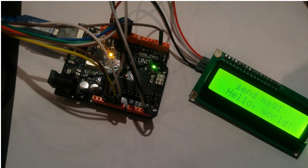
 Дисплеи Winstar на контроллере hd44780 довольно популярны, но их стандартное подключение к контроллеру по 16-и линиям не совсем удобно — масса проводов занимает драгоценные пины.
В данной ситуации есть выход — модуль I2C переходника. Подключается он всего по двум проводам. Но есть небольшие проблемы.
Сначала нужно скачать и установить библиотеку для работы с I2C дисплеем LiquidCrystal_I2C. Далее нужно задать адрес дисплея, указывается он в этой строке:
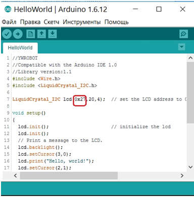
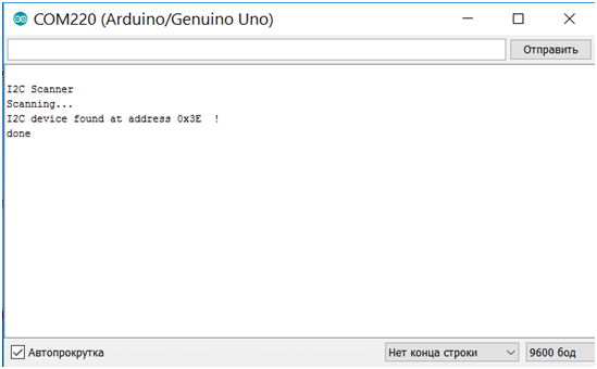
Адрес 0x27 стандартен для большинства модулей, но бывают и исключения из этого правила. Иногда он определяется как стандартный, но дисплей с ним не работает. Проверить адрес можно довольно просто, загрузив нижеприведенную программу (I2Cscanner) в плату Arduino:
#include <Wire.h>
void setup() {
Wire.begin();Serial.begin(9600);
while (!Serial);
Serial.println("nI2C Scanner");
}void loop() {
byte error, address;
int nDevices;Serial.println("Scanning...");
nDevices = 0;
for(address = 1; address < 127; address++ ) {
Wire.beginTransmission(address);
error = Wire.endTransmission();if (error == 0) {
Serial.print("I2C device found at address 0x");
if (address < 16) Serial.print("0");
Serial.print(address,HEX);
Serial.println(" !");
nDevices++;
}
else if ( error == 4) {
Serial.print("Unknow error at address 0x");
if (address < 16) Serial.print("0");
Serial.println(address,HEX);
}
}
if (nDevices == 0)
Serial.println("No I2C devices foundn");
else
Serial.println("donen");delay(5000);
}
Далее нужно открыть Serial Monitor и посмотреть считанный адрес. Но, как и говорилось ранее, иногда модуль по какой-то причине не работает с адресом 0x27. Что же делать?
В таком случае на плате модуля I2C существуют перемычки для переключения на другой адрес. На рисунке они обозначены как A0, A1, A2:
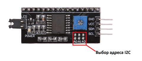
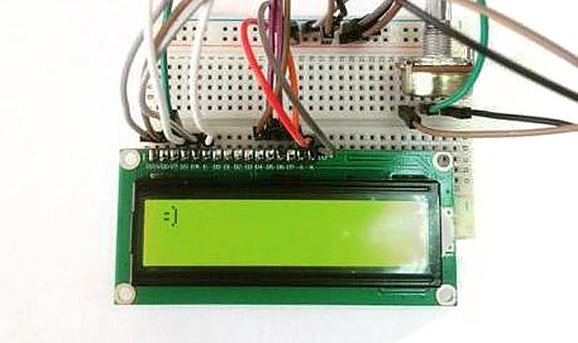
Замыкая какую либо из них, мы получаем новый адрес и все начинает работать. Например, замкнем A0. Загрузим скетч сканера на плату получим следующее:
Прописываем адрес в программу загружаем и видим, что всё работает нормально:
The imp API provides users of I²C peripheral devices (‘peripherals’) with debugging information following failed attempts to read or write data to any I²C peripheral connected to an imp. This information comes in the form of an integer constant returned by either i2c.write() or i2c.readerror(), depending on the type of operation being performed. If either method returns any value other than 0, an error has occurred. The return value indicates the nature of the error, and these errors are listed in the i2c.readerror() documentation. Should an error occur, the I²C transaction is abandoned.
This document describes these errors in more detail. They are presented in the order in which they are likely to be encountered, with those relating to write operations appearing first, followed by those issued during read operations.
The imp API makes sending and receiving data via I²C very straightforward, but ‘under the hood’ the process as is complex. As such, a single imp API I²C access may result in any one of a series of errors, depending on which stage of the process the underlying impOS™ I²C code has reached.

The I²C Protocol
Developers working with imp005-based devices should note that the following applies primarily to other imp devices. The imp005’s Broadcom SoC will report only two I²C error values: -13 and -9. The former is as described below, but the latter covers almost all of the remaining I²C errors: unfortunately, some error conditions aren’t reported at all (success is falsely indicated). We hope to improve imp005 I²C error reporting in a future version of impOS.
The Errors
Not Enabled (-13)
This is a straightforward error that is issued when you have attempted to access an imp I²C bus that has not yet been configured. Check your code and, if necessary, call i2c.configure() with a supported speed constant passed as a parameter.
Controller Select Error (-1)
The imp signals its intention to begin an I²C transaction by establishing the standard I²C start condition: it attempts to pull the SDA line low (so the waveform has a falling edge) while the SCL line remains high. If the imp is unable to pull SDA low, this error will be issued.
This error may arise if another I²C master is operating on the same bus and has taken control of it. If the imp is the only master on the bus, this error may result from poorly chosen pull-up resistors. I²C ports are open drain so can only pull the SDA and SCL lines low; pull-up resistors are required to drive the lines high when they are released by bus devices.
Transmit Select Error (-2)
After the imp has signalled start and is ready to write data to it, it sends the 7-bit address of the I²C peripheral it wants to communicate with, followed by a single bit indicating whether the transaction is a write (the imp pulls SDA low) or a read (the imp leaves SDA high). These eight bits should be acknowledged by a single-bit ACK signal from the peripheral at the transmitted address; it pulls SDA low. If the acknowledgement doesn’t occur during the ninth clock pulse, then the imp will issue this error.
If this error is encountered, check the value of the peripheral’s address that you are passing. Some devices have multiple addresses, selectable by setting an address pin to one of three states (high, low or floating). The imp API takes addresses in 8-bit form; 7-bit addresses will need to be bit-shifted left one place.
Transmit Error (-3)
BTF Error (-4)
Once the peripheral has acknowledged its readiness, the imp can begin to send the data it wants to write. Data is sent byte by byte, each one written to the imp’s data register from which it is passed to a shift register and from there out onto the bus one bit at a time. Once the peripheral has clocked in a byte of data, it should acknowledged receipt. If it fails to do so while the imp is processing any byte of the data but the last, a transmit error will be issued. If the error occurs sending the last byte, a BTF error is reported instead.
A transmit error may also be reported if the bit value clocked out is not seen on the bus, ie. the imp sends a 1, ie. it leaves the SDA line high, but the SDA line is pulled low. This could indicate bus contention — there is another master on the bus — or, more likely, that the I²C circuit’s pull-up resistors are too weak to keep the lines high.
Stop Error (-5)
Once the imp has successfully written all the data it wants to send to the peripheral (or read back all the data that it requested), it signals the completion of the transaction with a stop condition: while SCL is high, SDA is released to go high too (the waveform has a rising edge). This releases the bus for other devices to make use of it. Again, the imp checks that this stop signal has been sent correctly. If it has not, then this error will be issued.
Address Clear Error (-6)
During a read operation, the imp places on the bus the I²C address of the peripheral it wants to read data from. This event should be acknowledged by the peripheral. If it is not, the imp will return this error.
Address RXNE Error (-7)
Data RXNE Error (-8)
Controller Receive Select Error (-10)
Receive Error (-11)
BTF Receive Error (-14)
All of these errors indicate a failure to read a byte from the peripheral at some point during the read operation. This is often caused by the peripheral holding the SCL line low while it retrieves the requested byte(s) — a technique called ‘clock stretching’.
Which error you get will depend on the number of bytes you have requested to be read and on the exact point where the receive error occurred.
Reselect Error (-12)
If the imp wishes to read data from a specific peripheral register, it must first write that register’s address to the peripheral as a data value. After the register address has successfully been written, the imp initiates a read operation, to pick up the value the peripheral returns from the register. The imp switches from write mode to read mode by issuing a second start signal. Once again, it checks that it can proceed. If it is unable to do so within the timeout period, this error will be issued.