|
This article or section needs to be updated. Some information on it may be out of date, and should not be relied on. Please improve this article if you can. |
The Error Cluster is a predefined LabVIEW Cluster that is used to contain error status information. The cluster contains the following three components:
| Name | Data Type | Description |
|---|---|---|
| Status | Boolean | Indicates if an error has occurred (TRUE = error, FALSE = no error). |
| Code | 32-Bit signed integer | A standardized error code specific to the particular error. LabVIEW has a table of default error codes, although the user is able to define custom error codes. See below for more information. |
| Source | String | Textual information often describing the error and the VI it occurred within. |
An error cluster contains a Boolean “status”, an I32 numerical “code” and a “source” string in that order. Any cluster with this structure is treated as an error cluster in LabVIEW. The default value, “status” = false, “code” = 0 and “source” empty, is shown in Figure 1 for a typical control.
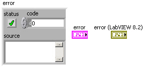
Figure 1: 3D error cluster control and terminal
Note that the default terminal and wire color was changed from pink to dark yellow in LabVIEW 8.2 (upgrade notes p. 35). The “status” is true if an error has occurred but remains false for warnings. The “code” assumes positive and negative values (see “error codes, ranges of” in LabVIEW Help).
Contents
- 1 Custom Error Codes
- 2 General Error Handling
- 2.1 Error Comparison
- 2.2 Error Selection
- 3 Error Cluster as Execution Order Specifier
- 4 Tips and tricks
- 5 See also
Custom Error Codes
The following ranges are reserved for developers to define their own error codes (see Custom Error Code):
- 5000 to 9999
- -8999 to -8000
- 500000 to 599999
Use Tools >> Advanced >> Edit Error Codes to create text files to define your own errors.
The “source” identifies a VI and possibly its call chain as the origin of an error. Possible reasons for an error can be obtained from the Explain Error tool (see Figure 2). This tool is activated by selecting the Explain Error… item under the Help menu in LabVIEW or by right-clicking on any element of an error cluster with “status” true and selecting Explain Error.
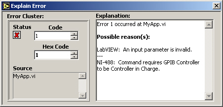
Figure 2: Explain Error tool
General Error Handling
LabVIEW provides several VIs for working with error clusters. For example, the Error Cluster from Error Code.vi generates an error cluster based on a specified “code” (see Figure 3). You can also define custom codes using the General Error Handler.vi or by creating an XML-based text file in the <labviewuser.lib errors> directory (see “error codes, defining custom” and “error codes, defining custom in text files” in LabVIEW Help). This VI outputs a “message”, like the “Explanation” from Explain Error, which identifies the “source” and describes possible causes associated with the “code”. This information can also be displayed using several different types of dialogs. This feature is commonly employed to identify errors in user interface applications.
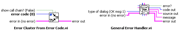
Figure 3: connectors for Error Cluster from Error Code.vi and General Error Handler.vi
Error Comparison
Error clusters are also valid inputs to some comparison and array functions and can be used to control case structures and while loops (see Figure 4).
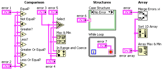
Figure 4: structures, comparison and array functions involving error cluster inputs
The comparison functions Equal?, Not Equal?, Greater?, Less?, Greater Or Equal? and Less Or Equal? can operate in two modes. The output is Boolean in the Compare Aggregates mode, while a cluster of three Booleans corresponding to each component of the error cluster is generated in the Compare Elements mode (see Figure 5).
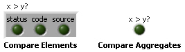
Figure 5: typical indicators for both modes of a comparison function
The Select, Max & Min and In Range and Coerce functions can output an error cluster. While the Max & Min function returns ordered inputs in the Compare Aggregates mode, an output may not correspond to either error cluster if Compare Elements is selected (default). The Array Max & Min function always returns ordered inputs corresponding to the first and last elements of the Sort 1D Array output. The primary sort is performed on “status”, with secondary ordering by “code” and then “source”. Strings are sorted by ASCII code starting with the leading character. Note that error clusters behave like their Boolean “status” value when connected to the selector terminal of a Select function and Case Structure or the conditional terminal of a While Loop.
Error Selection
A common programming issue in LabVIEW involves selecting between two or more error clusters. This process involves finding the cluster with “status” true or “code” not equal zero if no “status” is true. The Merge Errors.vi shown in Figure 4 implements this search for up to three error clusters and an array of such clusters. This subVI is relatively fast with large error arrays. However, a significant portion of the execution time involves concatenation of inputs for the small arrays (<10 elements) typical in most applications. This result suggests that time critical applications should be built around the immediate selection between two error clusters rather than their concatenation into an array. The simplest method of comparing the “status” of two error clusters involves the Select function (see Figure 6).
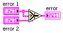
Figure 6: diagram for a simple error selector that does not detect warnings
This function selects the first error cluster with “status” true, much like the Or function operating on Boolean inputs. Connecting “error 2” instead of “error 1” to the selector terminal is more analogous to the And function, which is typically less useful. While about 30 times faster than the Merge Errors.vi (LabVIEW 7.0), the Select function does not detect a warning (“status” false and “code” not equal zero).
Diagrams for several VIs that compare error clusters and detect warnings are shown below (fastest to slowest).
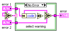
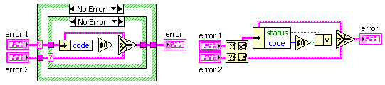
Figure 7: possible diagrams for an error selector that detects warnings
These VIs execute about 5 times faster than the Merge Errors.vi (LabVIEW 7.0), even with normal priority execution. (Merge Errors.vi uses the “subroutine” priority.) Inputs to selector terminals in the first and second diagrams are passed to “error” for the cases not shown. Otherwise, “error 1” is checked for nonzero “code” since neither cluster has “status” true. The last approach uses the Max & Min function in Compare Aggregates mode to order inputs. If just one of these clusters has “status” true, that input will be the “max” output since true > false. However, this output must be checked for “status” true or “code” nonzero to determine selection.
Error Cluster as Execution Order Specifier
LabVIEW is a dataflow language and as such preferred way to specify execution order of block diagram items is to connect output of a block diagram item to an input of another block diagram item. There are situations when some certain execution order is required but the outputs of the items to be executed earlier cannot be connected to the inputs of the items to be executed later. In these situations error cluster is a preferred way to specify the execution order of the items. It’s preferred over sequence structures in almost all use cases.
This can easily be achieved by a private replacement for the ‘merge errors’ node, that also contains a ‘No_Error’ constant:
 The connector pane looks like this:
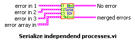
It can be used like this:
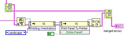
So a VI-Ref is opened independently if an error occured before, but after all preliminary portions of code had been finished. The printing actions relate to the eventual error of the OpenVI-Ref node only. All errors are merged as final action, so any error that might have shown up is reported, while the printing actions care only on VI-server related errors.
This little helper is too simple to provide its code as VI, though…
Tips and tricks
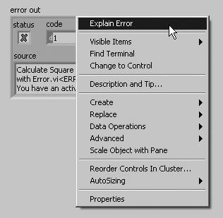
- Right-click the status button inside an error cluster on the front panel and select Explain Error to open the Explain Error dialog.
See also
- Error handling
- Error Case Structure
ERROR HANDLING
By default LABVIEW automatically handles any error that occurs when a VI runs by suspending execution, highlighting the subVI or function where the error occurred, and displaying a dialog box. You can choose other error handling methods. For example, if an I/O VI on the BLOCK DIAGRAM times out, you might not want the entire application to stop. You also might want the VI to retry for a certain period of time. In LabVIEW, you can make these error handling decisions on the block diagram of the VI.
VIs and functions return errors in one of two ways—with numeric error codes or with an error cluster. Typically, functions use numeric error codes, and VIs use an error cluster, usually with error inputs and outputs. Error handling in LABVIEW follows the data flow model. Just as data flow through a VI, we get an error information. Wire the error information from the beginning of the VI to the end. Include an error handler VI at the end of the VI to determine if the VI ran without errors. Use the error in and error out clusters in each VI you use or build to pass error information through the VI.
If you would like to Enrich your career with an Android certified professional, then visit Mindmajix — A Global online training platform: “LabVIEW training” Course.This course will help you to achieve excellence in this domain.
As the VI runs, LabVIEW tests for errors at each execution node. If LabVIEW does not find any errors, the node executes normally. If LabVIEW detects an error, the node passes the error to the next node without executing. The next node does the same thing and so on. Use the simple error handler VI, shown below Figure, to handle the error at the end of the execution flow. The simple error handler VI is located on the Functions» All Functions» Time & Dialog palette. Wire the error cluster to the error in input.
.png)
ERROR CLUSTER
Error clusters tell you why and where errors occur. When you perform any kind of I/O, consider the possibility that errors will occur. Almost all I/O functions return error information. Include error checking in VIs, especially for I/O operations such as file, serial, instrumentation, data acquisition, and communication operations, and provide a mechanism to handle errors appropriately. No matter how confident you are in the VI you create, you cannot predict every problem a user might encounter. Without a mechanism to check for errors, you know only that the VI does not work properly. Checking for errors in VIs can help you identify the following problems:
- You initialized communications incorrectly or wrote improper data to an external device.
- An external device lost power, is broken, or is not working properly.
- You upgraded the operating system software which changed the path to a file or the functionality of a VI or library. You might notice a problem in a VI or a system program.

Frequently Asked LabVIEW Interview Questions & Answers
The error clusters located on the Functions» All Functions» Array & Cluster palette include the following components of information which are also shown below Figure..png)
- status is a Boolean value that reports True if an error occurred. Most VIs, functions, and structures that accept Boolean data also recognize this parameter. For example, you can wire an error cluster to the Boolean inputs of the Stop, Quit LabVIEW, or Select If an error occurs, the error cluster passes a True value to the function.
- code is a 32-bit signed integer that identifies the error numerically. A non-zero error code coupled with a status of False signals a warning rather than a fatal error.
- the source is a string that identifies where the error occurred. Use the error cluster controls and indicators to create error inputs and outputs in subVIs.
When an error occurs, right-click within the cluster border and select Explain Error from the shortcut menu to open the Explain Error dialog box. The Explain Error dialog box contains information about the error. The shortcut menu includes an Explain Warning option if the VI contains warnings but no errors. You can also access the Explain Error dialog box from the Help» Explain Error menu.
Explore LabVIEW Sample Resumes! Download & Edit, Get Noticed by Top Employers!Download Now!
About Author

Ruchitha Geebu
I am Ruchitha, working as a content writer for MindMajix technologies. My writings focus on the latest technical software, tutorials, and innovations. I am also into research about AI and Neuromarketing. I am a media post-graduate from BCU – Birmingham, UK. Before, my writings focused on business articles on digital marketing and social media. You can connect with me on LinkedIn.

Урок 5 Отладка ВП
Как бы вы ни были уверены в создаваемом ВП, невозможно предусмотреть все проблемы, с которыми может столкнуться пользователь. Без механизма определения ошибок будет понятно только то, что ВП работает неправильно. Проверка на наличие ошибок позволит узнать, где именно и почему произошла ошибка.
Автоматическая обработка ошибок
Каждой ошибке соответствует числовой код и текстовое сообщение.
По умолчанию LabVIEW обрабатывает все ошибки, произошедшие во время выполнения ВП, следующим образом: ВП переводится в состояние ожидания, подВП или функция, где произошла ошибка, подсвечивается, а на экран выводится диалог ошибки.
Чтобы запретить автоматическую обработку ошибок для текущего ВП, выберите пункт меню File>>VI Properties, а затем Execution в
раскрывающемся меню Category. Чтобы запретить автоматическую обработку для всех вновь создаваемых ВП, выберите
Tools>>Options, а затем Block Diagram в списке Category. Чтобы запретить автоматическую обработку ошибок для подВП или функции, соедините выход error out с входом error in другого подВП или функции, либо с индикатором error out.
Ручная обработка ошибок
Можно выбирать другие методы обработки ошибок. Например, если для ВП ввода-вывода истекло время ожидания, не всегда нужно останавливать приложение и выводить диалог ошибки. Возможно, вы захотите, чтобы ВП повторял попытки в течение некоторого времени. Решения, связанные с обработкой ошибок, можно принимать на блок-диаграмме ВП.
Для управления ошибками предназначены ВП и функции обработки ошибок на палитре Dialog & User Interface, а также параметры error in и error out, присутствующие у большинства ВП и функций. Например, можно выводить сообщение об ошибке в диалогах различных видов. Используйте обработку ошибок совместно с инструментами отладки, чтобы эффективно находить и устранять ошибки в программе.
ВП и функции сообщают об ошибках либо при помощи числового кода, либо при помощи кластера ошибки. Как правило, числовые коды используются в функциях, а кластеры — в ВП, которые имеют для этого специальные входы и выходы.
При любых операциях ввода-вывода следует учитывать возможность ошибки. Почти все функции ввода-вывода возвращают информацию об ошибках. Наличие ошибок особенно важно проверять при работе с файлами, внешними приборами, устройствами сбора данных и при организации связи между компьютерами. Помимо проверки, следует реализовать механизм, адекватно обрабатывающий ошибки.
|
©National Instruments Corporation |
5-12 |
Учебный курс LabVIEW Основы I |
Урок 5 Отладка ВП
Обработкой ошибок можно управлять при помощи встроенных ВП, функций и параметров. Например, если LabVIEW обнаружит ошибку, вы можете сообщить о ней в окне диалога. Можно устранить ошибку программным способом, а затем удалить информацию о ней, соединив выход error out с входом error in ВП
Clear Errors. Компания National Instruments настоятельно рекомендует использовать обработку ошибок.
Кластеры ошибок
Элементы управления и индикаторы, представляющие кластеры ошибок, используются для передачи информации об ошибках между подВП.
Кластеры error in и error out содержат следующую информацию:
•status — логическое значение, в случае ошибки равно TRUE.
•code — 32-битовое знаковое целое, идентифицирующее ошибку. Ненулевой код и status = FALSE означают предупреждение.
•source — строка, идентифицирующая источник ошибки.
Обработка ошибок в LabVIEW соответствует модели потока данных. Информация об ошибках распространяется по ВП аналогично другим данным. Передавайте информацию об ошибках от начала до конца ВП, а в самом конце установите обработчик ошибок, чтобы определить, было ли выполнение безошибочным. Для передачи информации об ошибках используйте кластеры error in и error out. Их следует включать и в те ВП, которые вы строите самостоятельно.
Перед выполнением каждого узла блок-диаграммы LabVIEW проверяет наличие ошибок на его входе. Если ошибок нет, узел выполняется в нормальном режиме. Если ошибка обнаружена, она передается следующему узлу без выполнения текущей части кода. Следующий узел делает то же самое, и т. д. В конце потока выполнения LabVIEW сообщает об ошибке.
Объяснение ошибок
При возникновении ошибки щелкните правой кнопкой внутри кластера и выберите пункт Explain Error контекстного меню, чтобы открыть соответствующий диалог. Диалог Explain Error содержит информацию об ошибке. Если ошибок нет, но есть предупреждения, контекстное меню будет содержать пункт Explain Warning.
Диалог Explain Error также можно вызвать через пункт меню
Help>>Explain Error.
ВП и функции сообщают об ошибках либо при помощи числового кода, либо при помощи кластера ошибки. Как правило, числовые коды используются в функциях, а кластеры — в ВП, которые имеют для этого специальные входы и выходы.
Обработка ошибок при помощи структуры Case
В приведенном ниже примере кластер ошибки используется для выбора вариантов в структуре Case.
|
©National Instruments Corporation |
5-13 |
Учебный курс LabVIEW Основы I |

Урок 5 Отладка ВП
Рис. 5-3. Вариант No Error.
Рис. 5-4. Вариант Error.
При соединении кластера ошибки с терминалом селектора структуры Case, метка селектора автоматически показывает два варианта — Error и No Error, а рамка структуры меняет цвет на красный для варианта Error и зеленый для варианта No Error. При возникновении ошибки выполняется поддиаграмма Error.
Если с терминалом селектора соединен кластер ошибки, структура Case реагирует только на логический параметр status.
Обработка ошибок при помощи цикла While
Кластер ошибки можно соединить с терминалом условия цикла While. При этом на терминал передается только значение логического параметра status. Когда возникает ошибка, цикл останавливается.
Когда с терминалом условия соединен кластер ошибки, пункты контекстного меню Stop if True и Continue if True меняются на
Stop on Error и Continue while Error.
На рис. 5-5 кластер ошибки и кнопка останова совместно определяют условие выхода из цикла. Большинство циклов рекомендуется останавливать именно таким способом.
|
©National Instruments Corporation |
5-14 |
Учебный курс LabVIEW Основы I |
![]()
Урок 5 Отладка ВП
Рис. 5-5. Останов цикла While.
|
©National Instruments Corporation |
5-15 |
Учебный курс LabVIEW Основы I |
You might have already noticed the error cluster datatype, which is found on the Modern>>Array, Matrix & Cluster palette (Error In and Error Out, shown in Figure 7.64) and can also be found used in the inputs and outputs of many VIs and functions. The error cluster is a special datatype in LabVIEW (a cluster consisting of a status Boolean, code I32, and source string) that is used for propagating information about errors that occur during the execution of LabVIEW code. Errors and error handling are very naturalthere is no reason to be afraid of errors. Rather, we should understand how errors can occur, how to communicate errors, and how to handle errors.
Figure 7.64. Error In and Error Out controls found on the Array, Matrix & Cluster palette
So, what is an error? In simple terms, an error is an event where a function or subVI cannot complete a request because resources are not available or the information (arguments) passed to it are not valid.
In LabVIEW, we use dataflow to propagate information about errors inside of an error cluster datatype.
Error Cluster Datatype
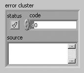
The error cluster (shown in Figure 7.65) contains three elements, as follows:
-
status BooleanSignifies whether there is an error (TRUE) or no error (FALSE).
-
code I32Is an error code signed integer that identifies the error.
-
Positive codes are errors.
-
Negative codes are warnings.
-
Zero is no error.
-
-
source stringIs a string that contains descriptive information about the source of the error. This commonly also contains a call chain, a list of VIs starting at the subVI (or function) where the error occurred and then listing up the call hierarchy, all the way up to the top-level VI.
Figure 7.65. Error cluster

Propagating Errors: Error Dataflow
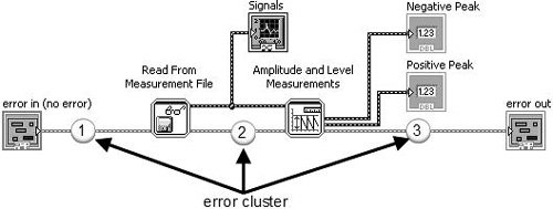
You use the error cluster datatype to store information about an error, and you use dataflow to propagate the error cluster through your block diagram. As you can see the example shown in Figure 7.66, an error cluster passes through the block diagram, connecting the following, in sequence:
-
error in control terminal to the Read From Measurement File subVI.
-
Read From Measurement File subVI to Amplitude and Level Measurements subVI.
-
Amplitude and Level Measurements subVI to the error out indicator terminal.
Figure 7.66. Block diagram showing how the error cluster is used to propagate errors using dataflow


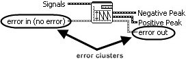
Many of LabVIEW’s functions and VIs have error in and error out terminals. These are almost always found (if present on the function or VI) on the lower-left and lower-right terminals of the connector pane (respectively). Figures 7.67 and 7.68 show the inputs and outputs of Read From Measurement File and Amplitude and Level Measurements with error in and error out highlighted.
Figure 7.67. Read From Measurement File
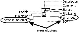
Figure 7.68. Amplitude and Level Measurements
Generating and Reacting to Errors in SubVIs
The expected behaviors of functions and VIs, with respect to generating and reacting to errors, are the following:
-
If error in contains an error (status = TRUE), do not do any work unless it is «clean up» work, such as
-
closing file references.
-
closing instrument or other communication references.
-
putting the system back into an idle/safe state (powering off motors, etc.).
-
-
If an error occurs inside of a function or VI, the function should pass out the error information via its error out indicator terminal unless it was passed in an error via its error in input terminal. In this case, just pass the incoming error from error in to error out, unchanged.
Error Case Structure
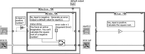
A subVI can fulfill expected behavior #1, by «wrapping» all of its functional code (its «work») inside of an Error Case Structure, which is simply a case structure that has an error cluster wired to its case selector terminal. As you can see in Figure 7.69, the Case Structure allows the error cluster datatype to be wired to its case selector terminal. When wired in this way, the Case Structure frame names change to «No Error» and «Error.» At run-time, if the error cluster does not contain an error, then the «No Error» frame will execute. Conversely, if the error cluster does contain an error, then the «Error» frame will execute.
Figure 7.69. An «Error Case Structure» containing an «Error» and «No Error» cases
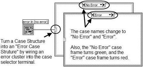
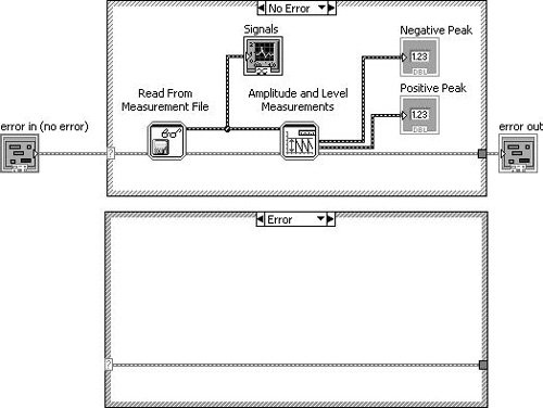
Figure 7.70 shows how we can use a case structure to conditionally execute our functional code only when there is no «upstream error» (using the dataflow vernacular).
Figure 7.70. An «Error Case Structure» used to execute code only when there is no «upstream error»
Merge Errors
But, what about the situation where you want to do some clean-up work, even if an upstream error has occurred? In this case, you should not wrap your functional code in an Error Case Structure, but rather, merge the error cluster flowing out of your work with the upstream error cluster using Merge Errors.vi, as shown in Figure 7.71.
Figure 7.71. Using Merge Errors.vi to combine several error clusters into a single error cluster
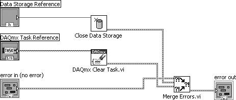

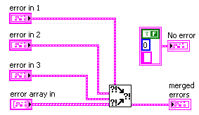
An error cluster can contain information about one, and only one, error. (This is a limitation in the data structure that carries a long legacy.) Merge Errors.vi merges several errors cluster inputs into a single error output. However, if there are errors in more than one input, it must choose which of these errors will take top priority and be passed to error out. It uses a top-to-bottom priority scheme, giving error in 1 top priority, then error in 2, and so on.
In the example shown in Figure 7.72, it is critical that the upstream error be wired to error in 1 (the top-most error input terminal) to ensure that the upstream error takes priority over any errors that occur inside our subVI.
Figure 7.72. Merge Errors.vi
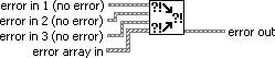
(Programming>>Dialog & User Interface palette). Merges error I/O clusters from different functions. This VI first looks for errors among error in 1, error in 2, and error in 3; then error array in and reports the first error found. If the VI finds no errors, it looks for warnings and returns the first warning found. If the VI finds no warnings, it returns no error.

Use merge errors to combine the error clusters of parallel tasks, or tasks that must each execute regardless of upstream errors.
Handling Errors in SubVIs
It is a good practice for a subVI to make a reasonable attempt to fulfill its contract (its stated job, per the software design requirements) in every way it can before passing an error up.
For example, imagine you are writing a routine that initializes an XY motion stage. (This might actually be the case, for some of our readers.) In order to find the home position (X = 0, Y = 0), the stage is moved at a low velocity toward a position sensor that outputs a digital signal of 1 (TRUE) when the stage reaches the home position. However, because there is a lot of electrical noise coming from the stage motors, the position sensor sometimes fails to report when the stage is at the home position (it sometimes jumps to 0, momentarily). This causes the initialization routine to fail at a rate of about one (1) out of twenty (20) tries, or 5% of the time. When it does fail, it always outputs the same error code. The noisy home position sensor signal has no other effect on the system, except for the occasional error during the homing operation.
Knowing what you know about the rate of failure and the type of failure, why not adapt your homing routine to retry (up to a certain number of times) before actually outputting an error message to the calling VI? This would make your code robust: fault tolerant and able to get the job done in spite of minor errors. Wouldn’t your end users be much happier if you made this change? Think of all those times they’ve started an experiment and came back to the lab an hour later expecting to find their experiment completed but, instead, they find that the system has generated that blankity-blank error while trying to home the stage… again!
OK, you agree that handling errors in subVIs is a great idea. Because the error cluster is just that, a cluster, you can use the cluster functions such as Unbundle By Name and Bundle By Name to access and modify the error data. For example, you can unbundle the error code.
Generating Errors in SubVIs
When you call a subVI or function and it generates an error, you can either try again (or perhaps try something else) or you can give up and propagate error (passing it downstream or up to the calling VI). But what happens when you want to generate a new error, perhaps because of an invalid input passed down from the calling VI? For this situation, you should use Error Cluster From Error Code.vi to generate a new error (see Figure 7.73).
Figure 7.73. Error Cluster From Error Code.vi
Error Cluster From Error Code.vi (Programming>>Dialog & User Interface palette) converts an error or warning code to an error cluster. This VI is useful when you receive a return value from a DLL call or when you return user-defined error codes.
For example, Figure 7.74 shows how we might generate an error in a subVI when an invalid argument is passed into the subVI (the TRUE case of the inner Case Structure is shown only for illustration purposes). In this example (which is located on the CD at EVERYONE/CH07/Calculate Square Root with Error.vi), we are calculating the square root of a number x. If x is negative, we will output an error (error code 1, which signifies an argument error) and default output data.
Figure 7.74. Calculate Square Root with Error.vi block diagram
Giving Up: Displaying Error Messages to the User
If error conditions cannot be handled by subVIs or in your top-level application, you can «give up» (but, please don’t accept defeat too easily) and display an error message to the user. This is the «last resort» of error handling. Figure 7.75 shows an error being passed to Simple Error Handler.vi (found on the Programming>>Dialog & User Interface palette) to display a dialog containing the error information. In this case, we passed a negative number to the subVI shown in Figure 7.74, which is an invalid input.
Figure 7.75. Calling Calculate Square Root with Error.vi as a subVI
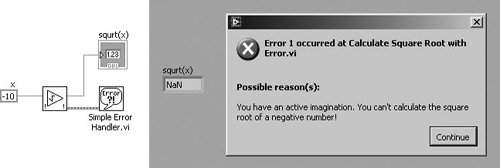
Figure 7.76. Simple Error Handler.vi
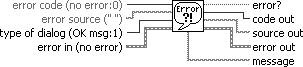
Simple Error Handler.vi (Programming>>Dialog & User Interface palette) indicates whether an error occurred. If an error occurred, this VI returns a description of the error and optionally displays a dialog box. This VI calls the General Error Handler VI and has the same basic functionality as General Error Handler but with fewer options.
Extra Tips for Error Handling
Use the following tips for successful error handling.
Use the Explain Error Dialog
When an error cluster control or indicator contains an error or warning, you can learn more about an error by selecting Explain Error from the cluster’s pop-up menu, as shown in Figure 7.77.
Figure 7.77. Selecting Explain Error from the pop-up menu of an error cluster to open the Explain Error dialog (shown in Figure 7.78)
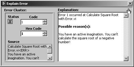
This will display the Explain Error dialog, as shown in Figure 7.78.
Figure 7.78. Explain Error dialog, which shows a detailed error explanation
Go with the Dataflow: Use Error In and Error Out Terminals
When you add error in and error out I/O terminals to your VIs, you allow calling VIs the opportunity to chain the error cluster wire to create dataflow dependencies between subVIs. Also, you are enabling applications to perform error handling, which is a good programming practice. Even if your subVI might not ever generate an error itself, put error I/O terminals on the front panel, and put an Error Case Structure on the block diagram (as you just learned) to allow errors to propagate through the software.
Make sure to wire error in to the lower-left terminal and error out to the lower-right terminal of the VI connector panethis is a best practice.
Define Your Own Errors: User-Defined Error Codes
For large applications, you might want to explore user-defined error codes, which are specific to your application. The LabVIEW Help documentation describes the process for defining and using this feature.
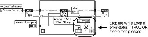
Don’t Get Stuck in a Loop: Test Error Status in Loops
It is almost always a good idea to check for errors inside of loops, so that you can exit the loop if an error occurs. Figure 7.79 shows how this is done. Note that the loop will stop if either the stop button is pressed or an error occurs.
Figure 7.79. Checking for errors in a While Loop to exit the loop when there is an error
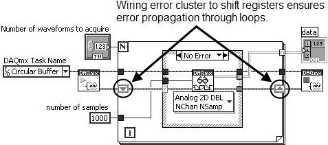
Use Shift Registers to Pass Errors Through Loops
Always use shift registers (not tunnels) for passing error clusters through the wall of a loop. This is especially important for a For Loop, as shown in Figure 7.80. Remember, if a For Loop executes zero times, data still passes from the input shift register to the output shift register. Wiring error clusters to shift registers on a For Loop ensures that errors propagate through the For Loop if it executes zero times.
Figure 7.80. Using shift registers to pass errors through loops