On a Layer 2 network, switches running STP, RSTP, MSTP, or VBST exchange BPDUs to calculate a spanning tree and trim the ring network into a loop-free tree topology. During the deployment of a spanning tree protocol, in most cases, the ports that connect switches to non-switching devices including user terminals (such as PCs) or file servers are configured as edge ports. These ports do not participate in spanning tree calculation and can transition from the Disable state to the Forwarding state immediately, as if the spanning tree protocol were disabled on these ports. When user terminals frequently go online and offline, configuring edge ports will prevent switches from recalculating the spanning tree topology, improving network reliability.
In Figure 1-1, the ports on S4, S5, and S6 connected to PCs are configured as edge ports. Normally, edge ports do not receive BPDUs. If forged BPDUs are sent to attack a device with edge ports and received by them, the device will automatically change the edge ports to non-edge ports and recalculate the spanning tree. If the bridge priority in the BPDUs sent by an attacker is higher than the priority of the root bridge, the network topology will change, thereby interrupting service traffic.
Figure 1-1 BPDU protection
After BPDU protection is enabled on a switch, if an edge port on the switch receives a BPDU, the switch will shut down the edge port, while keeping the port attribute unchanged. This ensures that the spanning tree topology is not recalculated and services are not interrupted. In addition, the switch generates the following log information and notifies the NMS of this event:
MSTP/4/BPDU_PROTECTION:This edged-port [port-name] that enabled BPDU-Protection will be shutdown, because it received BPDU packet!
Содержание
- error-down auto-recovery on Huawei switches
- error-down auto-recovery
- Function
- Format
- Parameters
- Views
- Default Level
- Usage Guidelines
- error-down auto-recovery
- Function
- Format
- Parameters
- Views
- Default Level
- Usage Guidelines
- Recovering an Interface From ERROR DOWN State
- Introduction
- Prerequisites
- Cause Description
- Recovery Measure
- Related Information
error-down auto-recovery on Huawei switches
Some of you may know Cisco’s err-disable recovery feature, which allows to automatically bring a port from err-disable back to UP state. Huawei switches have similar functionality, which is called error-down auto-recovery.
There are five reasons a port can enter into error-down state:
- BPDU protection
- EFM threshold
- EFM remote failure
- Auto defend
- Link flapping
- MAC address flapping
Let’s take a look, how this feature works, in a network running STP, when BPDU protection is the reason that a port goes into DOWN state. If you are not familiar with BPDU protection feature, read my previous article “Protecting STP on Huawei switches”.
I have configured STP BPDU protection on the Ethernet 0/0/1 interface of labnarioSW1 switch as follows:
Error-down auto-recovery feature has been enabled on the switch using command:
Option “interval” specifies how long (in seconds) our interface will be in DOWN state before it transitions to UP state. Any integer ranging from 30 to 86400 can be chosen.
On the other end of this Ethernet link labnarioSW2 switch is connected, to simulate STP attack. STP is temporary disabled on the Ethernet 0/0/1 port of the labnarioSW2, to prevent the Ethernet 0/0/1 port of the labnarioSW1 switch from transition to DOWN state.
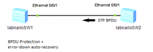
The only role of the labnarioSW2 switch is to generate BPDU frames. Any other device, which can send STP BPDU frames, can be connected as well. So let’s start sending STP BPDUs:
Please see log messages, generated by the BPDU protection and error-down auto-recovery feature, enabled on labnarioSW1 switch:
To display the status of the error-down auto-recovery, use the command:
After 30 seconds, error-down auto-recovery feature transitions port back to UP state:
Источник
error-down auto-recovery
Function
The error-down auto-recovery command enables an interface in Error-Down state to go Up automatically and sets the auto recovery delay.
The undo error-down auto-recovery command disables an interface in Error-Down state from going Up automatically.
By default, an interface in Error-Down state is disabled from going Up automatically.
An interface enters the Error-Down state after being shut down due to an error. Currently, errors include BPDU protection .
Format
Parameters
cause
Indicates the cause for an interface in Error-Down state.
bpdu-protection
Indicates that an interface enters the Down state because STP BPDU protection is enabled.
efm-remote-failure
Indicates that an interface enters the Down state due to an EFM remote failure event.
efm-threshold-event
Indicates that an interface enters the Down state due to an EFM threshold crossing event.
interval interval-value
Specifies the auto recovery delay.
Views
Default Level
2: Configuration level
Usage Guidelines
Usage Scenario
Cause for an Interface in Error-Down State
bpdu-protection
On an STP-enabled network where BPDU protection is configured on an edge port, if attackers send bogus BPDUs to attack the switching device, the switching device sets the edge port status to Down immediately after the edge port receives BPDUs. As a result, all services on the edge port are interrupted.
For details, see stp bpdu-protection .
efm-remote-failure
The efm trigger error-down command associates an EFM remote failure event with an interface. When EFM detects critical-event , dying-gasp , link-fault , or timeout failure events, the protocol status of the interface becomes Down and all services on the interface are interrupted.
efm-threshold-event
When link monitoring is configured for an interface on a link, the link is considered unavailable if the number of errored frames, errored codes, or errored frame seconds detected by the interface reaches or exceeds the threshold within the specified detection period. You can associate an EFM threshold crossing event with an interface. The system then sets the status of the interface to Down. In this manner, all services on the interface are interrupted.
By default, if an interface enters the Down status in the preceding scenarios listed in the table, the interface can only be manually recovered by the network administrator. To configure the interface to restore to the Up state automatically, run the error-down auto-recovery command. This command also set an auto recovery delay. After the delay, the interface goes Up automatically.
The restored interface is shut down again if the interface receives BPDUs again or the link is considered unavailable during a specified period.
Precautions
You can specify the auto recovery delay using interval in the error-down auto-recovery command. The error-down auto-recovery command is invalid for the interface that has been in Error-Down state. It takes effect only for the interface that enters the Error-Down state after the error-down auto-recovery command is executed.
BPDU protection has been enabled using the stp bpdu-protection command in the system view.
An EFM threshold crossing event has been associated with an interface using the efm threshold-event trigger error-down command in the interface view. An EFM remote failure event has been associated with an interface using the efm trigger error-down command in the interface view.
Источник
Recovering an Interface From ERROR DOWN State
Introduction
You may find that a physical interface on a switch is in ERROR DOWN state, and want to figure out why the interface is in such a state and how to restore the interface. This document describes the ERROR DOWN state and how to restore an interface in this state.
Prerequisites
This document applies to S series switches in V200R001C00 and later versions. The down-cause field value varies depending on the version and product model.
Cause Description
In any view of the interconnected two devices, run the display interface interface-type interface-number command to check the current running status and statistics of the specified interface. The current state field displays ERROR DOWN( down-cause). The following uses ERROR DOWN(as-not-ready) as an example.
Recovery Measure
If the current state field displays ERROR DOWN (down-cause), check whether the interface is shut down because of error events. You need to rectify the fault according to the down-cause field. The following table lists common values of the down-cause field.
Value of the down-cause Field
When the device negotiates to the AS mode, its interface status becomes Down and then becomes Up after services in the service profiles have been delivered.
After the auto-defend action command is used to configure actions against attack sources, the interface that receives attack packets is shut down to prevent the device from attacks.
On an STP-enabled network, after BPDU protection is configured on edge interfaces of a switch, the switch sets the physical status of the edge interface that receives BPDUs to Down to block services on this interface if the switch is attacked by forged BPDUs.
When the efm trigger error-down command associates a remote fault event with the current interface of a switch, the switch sets the protocol status of the interface to Down to interrupt all services on the interface if EFM detects the critical-event, dying-gasp, link-fault, or timeout fault event.
When link monitoring is configured for an interface on a link, the link is considered unavailable if the number of errored frames, errored codes, or errored frame seconds detected by the interface reaches or exceeds the threshold within a specified period. You can associate an EFM crossing event with the current interface. The system then sets the administrative status of the interface to Down. In this manner, all services on the interface are interrupted.
When an Ethernet interface configured with a backup link receives error packets, faults such as service packet loss occur. To ensure nonstop service transmission, when the number of received error packets reaches the alarm threshold, the interface is shut down and services are switched to the backup link.
An interface receives Runts error packets if the optical fiber, network cable, or optical module is removed and reinstalled, the shutdown or undo shutdown command is executed, or Runts packets are forwarded on the network. To avoid worse impact on the device or services, the device counts the number of Runts error packets received by an interface within 1 minute, and shuts down the interface if the number reaches the alarm threshold 5.
Cable faults or active/standby switchovers will cause an interface to frequently alternate between Up and Down. You can configure link flapping protection on interfaces. When the switch receives an interface Up/Down message, it checks the number of interface flappings and interval. If the number of interface flappings within the specified period reaches the configured limit, the switch shuts down the interface.
After the storm control action is configured as error-down on an interface, the interface is shut down when the average rate of received broadcast, multicast, and unknown unicast packets is larger than the specified limit within the interval for detecting storms.
When interface security is configured on a switch, the MAC addresses learned by the switch become secure dynamic MAC addresses. If the port-security protect-action command sets the security protection action to shutdown on an interface, the interface is shut down when the number of secure MAC addresses learned by the interface exceeds the upper limit or static MAC address flapping is detected after static MAC address detection is enabled.
When MAC address flapping occurs on a user network because of loops, you can configure a loop prevention action for the switch to perform when MAC address flapping occurs. After the MAC address flapping action is configured on an interface, if the switch detects MAC address flapping on the interface, it sets the physical status of the interface to Down.
When the optical power of an Ethernet optical interface configured with a backup link is reduced, faults such as packet loss occur. To ensure normal service operation, the interface is triggered to transit to the Error-Down state and services are switched immediately if the optical power is lower than the lower alarm threshold.
After the switch runs for a long time, the chip memory identifier has a data integrity error.
You can recover an interface from the ERROR DOWN state using either of the following measures:
Run the shutdown and undo shutdown commands or run the restart command in the interface view to restart the interface.
Run the error-down auto-recovery cause down-cause interval interval-value command in the system view to enable an interface in ERROR DOWN state due to the cause indicated by the down-cause field to go Up and set the automatic recovery delay.
For example, the current state field is displayed as ERROR DOWN(auto-defend) for GE0/0/1. You can run the following command to enable the interface to go Up after 30 seconds.
When the interface is in Up state, you can then check the services to figure out why the interface enters the ERROR DOWN state for rectifying the fault.
Manual recovery or automatic recovery can only temporarily restore an interface in ERROR DOWN state. You need to troubleshoot the services to rectify the fault that causes the interface to enter the ERROR DOWN state. Otherwise, even if the interface recovers from the ERROR DOWN state, it will enter this state again unless the fault is rectified.
For details about troubleshooting an ethernet interface in physically down state, refer to Huawei S Series Campus Switches Troubleshooting Guide—Troubleshooting: Ethernet Interface Physically Down.
Источник
Some of you may know Cisco’s err-disable recovery feature, which allows to automatically bring a port from err-disable back to UP state. Huawei switches have similar functionality, which is called error-down auto-recovery.
There are five reasons a port can enter into error-down state:
- BPDU protection
- EFM threshold
- EFM remote failure
- Auto defend
- Link flapping
- MAC address flapping
Let’s take a look, how this feature works, in a network running STP, when BPDU protection is the reason that a port goes into DOWN state. If you are not familiar with BPDU protection feature, read my previous article “Protecting STP on Huawei switches”.
I have configured STP BPDU protection on the Ethernet 0/0/1 interface of labnarioSW1 switch as follows:
[labnarioSW1]int e0/0/1
[labnarioSW1-Ethernet0/0/1]stp edged-port enable
[labnarioSW1]stp bpdu-protection
Error-down auto-recovery feature has been enabled on the switch using command:
[labnarioSW1]error-down auto-recovery cause bpdu-protection interval 30
Option “interval” specifies how long (in seconds) our interface will be in DOWN state before it transitions to UP state. Any integer ranging from 30 to 86400 can be chosen.
On the other end of this Ethernet link labnarioSW2 switch is connected, to simulate STP attack. STP is temporary disabled on the Ethernet 0/0/1 port of the labnarioSW2, to prevent the Ethernet 0/0/1 port of the labnarioSW1 switch from transition to DOWN state.
The only role of the labnarioSW2 switch is to generate BPDU frames. Any other device, which can send STP BPDU frames, can be connected as well. So let’s start sending STP BPDUs:
[labnarioSW2-Ethernet0/0/1]stp enable
Please see log messages, generated by the BPDU protection and error-down auto-recovery feature, enabled on labnarioSW1 switch:
[labnarioSW1]
May 23 2013 21:30:34-08:00 labnarioSW1 %%01MSTP/4/BPDU_PROTECTION(l)[62]:This edged-port Ethernet0/0/1 that enabled BPDU-Protection will be shutdown, because it received BPDU packet!
May 23 2013 21:30:34-08:00 labnarioSW1 %%01ERRDOWN/4/ERRDOWN_DOWNNOTIFY(l)[63]:Notify interface to change status to error-down. (InterfaceName=Ethernet0/0/1, Cause=bpdu-protection)
May 23 2013 21:30:34-08:00 labnarioSW1 ERRDOWN/4/ErrordownOccur:OID 1.3.6.1.4.1.2011.5.25.257.2.1 Error-down occured. (Ifindex=6, Ifname=Ethernet0/0/1, Cause=bpdu-protection)
May 23 2013 21:30:34-08:00 labnarioSW1 %%01PHY/1/PHY(l)[64]: Ethernet0/0/1: change status to down
To display the status of the error-down auto-recovery, use the command:
[labnarioSW1]display error-down recovery int e0/0/1
  interface                      error-down cause          recovery   remainder time(sec)
  ------------------------------------------------------------------------------
  Ethernet0/0/1                  bpdu-protection           30         17

[labnarioSW1]display error-down recovery int e0/0/1
  interface                      error-down cause          recovery   remainder time(sec)
  ------------------------------------------------------------------------------
  Ethernet0/0/1                  bpdu-protection           30         8

[labnarioSW1]display error-down recovery int e0/0/1
  interface                      error-down cause          recovery   remainder time(sec)
  ------------------------------------------------------------------------------
  Ethernet0/0/1                  bpdu-protection           30         3
After 30 seconds, error-down auto-recovery feature transitions port back to UP state:
May 23 2013 21:31:03-08:00 labnarioSW1 %%01ERRDOWN/4/ERRDOWN_DOWNRECOVER(l)[67]:Notify interface to recover state from error-down. (InterfaceName=Ethernet0/0/1) May 23 2013 21:31:03-08:00 labnarioSW1 ERRDOWN/4/ErrordownRecover:OID 1.3.6.1.4.1.2011.5.25.257.2.2 Error-down recovered. (Ifindex=6, Ifname=Ethernet0/0/1, Cause=bpdu-protection, RecoverType=auto recovery) May 23 2013 21:31:05-08:00 labnarioSW1 %%01PHY/1/PHY(l)[68]: Ethernet0/0/1: change status to up
Huawei uses machine translation combined with human proofreading to translate this document to different languages in order to help you better understand the content of this document.
Note: Even the most advanced machine translation cannot match the quality of professional translators.
Huawei shall not bear any responsibility for translation accuracy and it is recommended that you refer to the English document (a link for which has been provided).
ERRORDOWN
- ERRDOWN_1.3.6.1.4.1.2011.5.25.257.2.1 hwErrordown
- ERRDOWN_1.3.6.1.4.1.2011.5.25.257.2.2 hwErrordownRecovery
ERRDOWN_1.3.6.1.4.1.2011.5.25.257.2.1 hwErrordown
Description
ERRDOWN/4/ErrordownOccur: OID [oid] Error-down occurred. (Ifindex=[INTEGER], Ifname=[STRING], Cause=[STRING])
The alarm was generated when an errordown event occurred.
Attribute
| Alarm ID | Alarm Severity | Alarm Type |
|---|---|---|
|
1.3.6.1.4.1.2011.5.25.257.2.1 |
Warning |
communicationsAlarm(2) |
Parameters
| Name | Meaning |
|---|---|
|
oid |
Indicates the MIB object ID of the alarm. |
|
IfIndex |
Index of an interface. |
|
Ifname |
Interface name. |
|
Cause |
Cause of the errordown event. |
Impact on the System
After the errordown event occurs, traffic cannot be forwarded on relevant interfaces and services are interrupted.
Possible Causes
The faults detected by service modules triggered errordown events. The possible causes are as follows:
-
EFM detected a link fault, which can be a fault that occurred on the remote end or a threshold-crossing event.
-
The MSTP edge port received BPDU packets.
-
After the number of secure MAC addresses learned by an interface reaches the maximum value, the interface receives packets from another MAC address.
-
MAC address flapping occurred.
-
The number of CRC error packets received by the interface during the alarm interval reached the alarm threshold.
-
The number of link flappings during the link flapping period reached the alarm threshold.
-
The current optical power of the interface fell below the lower alarm threshold.
-
Attack packets occurred on the interface.
-
The number of Runts error packets received by the interface reached the alarm threshold.
Only the S5720-EI supports the alarm indicating that the number of received Runts error packets reaches the alarm threshold.
Procedure
- Locate the fault based on the value of the Cause field in the alarm.
-
If the value of the Cause field is bpdu-protection, go to Step 2.
-
If the value of the error-down cause field is port-security, rectify the fault according to the log L2IFPPI_1.3.6.1.4.1.2011.5.25.315.3.2 hwPortVlanSecureMacAlarm.
-
If the value of the error-down cause field is mac-address-flapping, rectify the fault according to the log L2IFPPI_1.3.6.1.4.1.2011.5.25.160.3.7 hwMflpVlanAlarm.
-
If the value of the Cause field is efm-threshold-event, rectify the fault according to the log EFM_1.3.6.1.4.1.2011.5.25.136.1.6.4 hwDot3ahEfmThresholdEvent.
-
If the value of the Cause field is efm-remote-failure, rectify the fault according to the log EFM_1.3.6.1.4.1.2011.5.25.136.1.6.5 hwDot3ahEfmNonThresholdEvent.
-
If the value of the error-down cause field is error-statistics, rectify the fault according to the log IFNET_1.3.6.1.4.1.2011.5.25.41.4.1 hwIfMonitorCrcErrorRising.
-
If the value of the error-down cause field is link-flap, rectify the fault according to the section An Ethernet Interface Frequently Alternates Between Up and Down States in «Ethernet Interface Configuration» in the S2720, S5700, and S6700 V200R019C00 Configuration Guide — Interface Management.
-
If the value of the error-down cause field is transceiver-power-low, rectify the fault according to the log ENTITYTRAP_1.3.6.1.4.1.2011.5.25.219.2.4.5 hwOpticalInvalid 136194.
-
If the value of the error-down cause field is auto-defend, rectify the fault according to the next log.
- SECE_1.3.6.1.4.1.2011.5.25.165.2.2.1.1 hwStrackUserInfo
- SECE_1.3.6.1.4.1.2011.5.25.165.2.2.1.2 hwStrackIfVlanInfo
- SECE_1.3.6.1.4.1.2011.5.25.165.2.2.1.5 hwStrackIPInfo
-
If the value of the Cause field is runts-error-statistics, go to step 4.
-
- Check whether the interface is specified as an edge port.
-
If the interface is not specified as an edge port, go to Step 3.
-
If the interface is specified as an edge port, go to Step 5.
-
- Perform the following steps.
-
Run:
interface interface-type interface-num
The interface view is displayed.
-
Run:
undo stp edged-port and undo shutdown
The edge port configuration is removed. Check whether the log still exists. If the log still exists, go to Step 5.
-
- Perform the following steps.
- If the interface is an optical interface, check whether the optical fiber or optical module is removed and reinstalled. If the interface is an electrical interface, check whether the network cable is removed and reinstalled. If not, go to step b.
- Run the display history-command command to check whether the shutdown or undo shutdown command has been executed on the interface. If not, go to step c.
- Check whether the physical link is faulty. If not, the interface may be attacked using Runts error packets. Check the log to find out the attack source and take measures to defend against the attack. If the fault persists, go to step 5.
- Collect log messages and contact technical support personnel.
ERRDOWN_1.3.6.1.4.1.2011.5.25.257.2.2 hwErrordownRecovery
Description
ERRDOWN/4/ErrordownRecover: OID [oid] Error-down recovered.
(Ifindex=[INTEGER], Ifname=[STRING], Cause=[STRING], RecoverType=[STRING])
The error-down fault recovered.
Attribute
| Alarm ID | Alarm Severity | Alarm Type |
|---|---|---|
| 1.3.6.1.4.1.2011.5.25.257.2.2 | Warning | communicationsAlarm(2) |
Parameters
| Name | Meaning |
|---|---|
| oid | Indicates the MIB object ID of the alarm. |
| Ifindex | Index of an interface. |
| Ifname | Interface name. |
| Cause | Cause of an alarm. |
| RecoverType | Recovery type: automatic recovery or recovery using a command line. |
Impact on the System
Services will not be affected.
Possible Causes
-
Services that generated the errordown events were unbound from
the errordown module. -
Services associated with the errordown events recovered.
Procedure
- This log message is informational only, and no action is
required.
- ERRDOWN_1.3.6.1.4.1.2011.5.25.257.2.1 hwErrordown
- ERRDOWN_1.3.6.1.4.1.2011.5.25.257.2.2 hwErrordownRecovery
Введение в RSTP
Обзор RSTP:
Протокол Rapid Spanning Tree Protocol (RSTP) реализует быструю конвергенцию на основе STP и добавляет концепцию и функции защиты граничных портов.
Роль порта RSTP:
RSTP добавляет две новые роли порта на основе STP: порт резервного копирования и пограничный порт. Добавление ролей портов упрощает понимание и развертывание протокола связующего дерева.
- Резервный порт: порт заблокирован из-за изучения отправленного им сообщения BPDU конфигурации. Резервное копирование назначенного порта обеспечивает другой резервный путь от корневого узла к конечному узлу.
- Граничный порт: если порт расположен на краю всей коммутационной зоны и не подключен к какому-либо коммутационному оборудованию, этот тип порта называется граничным портом. Граничный порт обычно напрямую подключается к пользовательскому терминальному устройству.

Рис.: Схема ролей порта RSTP
Особенности граничных портов:
- Граничный порт сохранит 30-секундную задержку, и порт перейдет в состояние пересылки сразу после того, как он станет UP.
- ВВЕРХ / ВНИЗ граничного порта не вызовет изменения топологии.
- Пакет BPDU конфигурации, полученный пограничным портом с установленным TC, не будет устанавливать время устаревания MAC-адреса на 15 секунд.
- Если граничный порт получает настроенное сообщение BPDU, он немедленно становится обычным портом ‘’ порта для конвергенции STP.
- Граничный порт также отправляет сообщения BPDU конфигурации.
- Согласование PA не блокирует граничные порты.
Статус порта RSTP:
Статус порта RSTP был улучшен на основе STP. Уменьшено с исходных пяти до трех.
| Статус порта | Описание |
|---|---|
| Forwarding | В этом состоянии порт не только пересылает пользовательский трафик, но и обрабатывает сообщения BPDU. |
| Обучение | Это переходное состояние. В разделе «Обучение» коммутирующее устройство создает таблицу MAC-адресов на основе полученного пользовательского трафика, но не пересылает пользовательский трафик, поэтому это называется состоянием обучения. Порт в состоянии обучения обрабатывает пакеты BPDU и не пересылает пользовательский трафик. |
| Отбросив | Порт в состоянии Discarding принимает только пакеты BPDU. |
Примечание:
Статус порта MSTP такой же, как статус порта RSTP.
По умолчанию оборудование Huawei для передачи данных находится в режиме MSTP. При переключении из режима MSTP в режим STP статус порта, поддерживаемый портом на устройстве, на котором запущен STP, остается таким же, как статус порта, поддерживаемый MSTP. Поддерживаемый статус включает только пересылку и обучение. И отбрасывая
Сообщение RSTP:
Формат сообщения RSTP:
В дополнение к обеспечению соответствия формата BPDU формату STP, в RSTP были внесены некоторые незначительные изменения. Один находится в поле Тип, тип BPDU конфигурации больше не 0, а 2, и номер версии также стал 2. Таким образом, коммутатор, на котором запущен протокол STP, отбрасывает этот тип BPDU при его получении.
Другое изменение — использовать изначально зарезервированные средние 6 бит в поле флага. Измененный таким образом конфигурационный BPDU называется RST BPDU.
Формат поля флага RSTP:
- Bit7:TCA
- Bit6:Agreement
- Bit5:Forwarding
- Bit4:Learning
- Bit3 и Bit2: роль порта
- 00: неизвестно
- 01: корневой порт
- 10:Alternate / Backup
- 11: назначенный порт
- Bit1:Proposal
- Bit0:TC
Пример захвата пакета RSTP:

Рис.: Пример захвата пакета RSTP
Механизм быстрой сходимости RSTP:
P / A переговоры:
Ввиду проблемы, заключающейся в том, что для запуска оборудования STP от инициализации до полной конвергенции требуется не менее 30 секунд, RSTP использует механизм согласования P / A (предложение / соглашение).
Особенности:
Благодаря возвратно-поступательному механизму подтверждения и механизму переменной синхронизации нет необходимости полагаться на таймер, чтобы гарантировать отсутствие циклов. Интерфейс подключения коммутатора может быстро перейти в режим пересылки.
Условия оборудования для согласования P / A:
Его можно применить только к двухточечному каналу (полнодуплексный порт). Если это полудуплексный порт, он будет распознан как общий (общий) канал. Согласование P / A нельзя использовать для общего канала.
Процесс согласования P / A:
- SW1 отправляет пакет BPDU с p, установленным в SW2.
- Синхронизируйте переменные (блокируйте порты, отличные от граничных портов, для предотвращения петель).
- SW2 отправляет пакет BPDU с A, установленным в SW1.
- После того, как SW1 получает пакет BPDU с установленным A, порт немедленно переходит в состояние пересылки. (Обычно в секундах)
Подробный процесс переговоров по P / A:

Рис.: Подробный процесс согласования P / A
При каких обстоятельствах нужно установить бит предложения в сообщении RSTP?
Когда назначенный порт переходит в состояние отбрасывания или обучения, предложение должно быть установлено.
Оптимизация времени сходимости в RSTP:
- Согласование P / A: Интерфейс соединения RP и DP коммутатора может быстро перейти в состояние пересылки.
- Ошибка прямого подключения: порт AP становится RP и быстро переходит в состояние пересылки без задержки 30 секунд.
- Неоптимальный сценарий: после получения неоптимального пакета RST BPDU порт AP немедленно становится портом DP и отправляет на порт оптимальный пакет RST BPDU.
- Отказ канала с непрямым подключением: если три последовательных пакета RST BPDU потеряны, необходимо переключить роль порта. Максимальное время — 6 с.
- Все мостовые устройства могут отправлять пакеты RST BPDU с TC, установленным в RSTP в течение 4 секунд (TC пока время).
При каких обстоятельствах пакеты TC BPDU будут отправляться в RSTP?
Назначенный порт переходит в состояние пересылки.
Очистка таблицы MAC-адресов:
- Отправитель TC: очистите записи привязки MAC-адреса для других портов, кроме граничного порта.
- Приемник TC: очистите записи привязки MAC-адресов для портов, отличных от портов интерфейса сообщений TC и граничных портов.
В RSTP некорневые мосты также будут активно отправлять RsT BPDU каждый таймер приветствия, а не через корневой мост.
После того, как порт DP отключен в RSTP, роль порта BP немедленно станет портом DP и войдет в состояние пересылки после 30-секундной задержки пересылки.
Функция защиты RSTP:
| Защитная функция | Сцены | Влияние конфигурации |
|---|---|---|
| Защита BPDU (Bridge Protocol Data Unit) | После того, как граничный порт получит BPDU, статус порта изменится на не граничный порт, что приведет к перерасчету связующего дерева. Если злоумышленник подделывает сообщения конфигурации для злонамеренной атаки на коммутационное устройство, это вызовет сетевой шок. | После включения функции защиты BPDU на коммутационном устройстве, если граничный порт получает RST BPDU, граничный порт будет отключен из-за ошибки, но атрибут граничного порта останется неизменным, и система управления сетью получит уведомление. Граничные порты, которые вышли из строя, могут быть восстановлены вручную только администратором сети. Если пользователю необходимо автоматически восстановить граничный порт, в котором произошла ошибка, функция автоматического восстановления порта может быть активирована конфигурацией, и может быть установлено время задержки. |
| Защита от атак пакетов Anti-TC-BPDU | После того как коммутационное устройство получит сообщение об изменении топологии, оно удалит запись таблицы MAC-адресов и запись таблицы ARP.Частые операции будут иметь большое влияние на ЦП. | После включения функции пакетной атаки против TC-BPDU можно настроить количество раз, когда коммутационное устройство обрабатывает пакеты изменения топологии за единицу времени. Если количество пакетов изменения топологии, полученных коммутационным устройством за единицу времени, превышает настроенный порог, устройство будет обрабатывать только количество раз, указанное пороговым значением. Для других пакетов изменения топологии, которые превышают пороговое значение, устройство обрабатывает их только один раз после истечения таймера. Это позволяет избежать частого удаления записей таблицы MAC-адресов и записей таблицы ARP, тем самым достигая цели защиты устройства. |
| Защита корней | Из-за неправильной настройки обслуживающего персонала или злонамеренных атак на сеть корневой мост получает BPDU с более высоким приоритетом и теряет статус корневого моста, пересчитывает связующее дерево и может вызвать высокоскоростную миграцию трафика из-за изменений топологии. К низкоскоростному каналу, вызывая перегрузку сети. | Для назначенного порта с включенной защитой от корня его роль порта может поддерживаться только как назначенный порт. Как только назначенный порт с включенной функцией защиты от корня получит RST BPDU с более высоким приоритетом, состояние порта перейдет в состояние Discarding и перестанет пересылать пакеты. По прошествии определенного периода времени (обычно вдвое превышающего задержку пересылки), если порт не получил более высокий приоритет RST BPDU, порт автоматически вернется в нормальное состояние пересылки. |
| Защита от петель | Когда происходит перегрузка канала или сбой однонаправленного канала, корневой порт и альтернативный порт устареют. Старение корневого порта приведет к тому, что система повторно выберет корневой порт (и это может быть неправильным), а старение альтернативного порта перейдет в состояние пересылки, что вызовет петлю. | После включения функции защиты от петель, если корневой порт или альтернативный порт не может получать пакеты BPDU от вышестоящего устройства в течение длительного времени, он отправит уведомление в управление сетью (корневой порт в это время перейдет в состояние Discarding, и роль будет переключена на назначенный порт. ), а альтернативный порт всегда будет оставаться в заблокированном состоянии (роль также будет переключена на назначенный порт) и не будет пересылать пакеты, так что в сети не будет образовываться петля. До тех пор, пока канал не перестанет быть перегруженным или однонаправленный канал не восстановится, порт повторно получит сообщение BPDU для согласования и возобновит свою роль и состояние до того, как канал будет перегружен или однонаправленный канал не откажет. |
— stp root-protection
// Корневая защита должна быть включена на всех назначенных портах.Если активированный порт получает пакет BPDU, который лучше, чем корневой мост, статус порта изменится на статус Discarding. Если пакеты BPDU с улучшенным качеством не получены от порта в течение непрерывного периода MAX age, порт автоматически вернется в состояние пересылки. , Предотвратить вытеснение рута.
-
stp loop-protection
// Используется для портов RP и AP. Порт для приема пакетов BPDU. Предотвращение зацикливания, вызванного отказом однонаправленного канала.
-
TC-protection
// Устанавливаем количество ответов на пакеты TC. Если количество принятых TC больше, чем количество TC в пределах порогового диапазона, превышающая часть будет выполнена только один раз.
-
BPDU-protection
// Настроить защиту BPDU
Команды настройки RSTP:
Базовая конфигурация такая же, как и в командной строке конфигурации STP.
[Просмотр интерфейса] stp точка-точка { auto | force-false | force-true}
// Настраиваем тип ссылки для указанного порта. По умолчанию назначенный порт автоматически распознает, подключен ли он к каналу «точка-точка», а канал «точка-точка» поддерживает быструю конвергенцию.
// Если текущий порт Ethernet работает в полнодуплексном режиме, канал, подключенный к текущему порту, является двухточечным каналом, выберите параметр force-true для достижения быстрой конвергенции.
// Если текущий порт Ethernet работает в полудуплексном режиме, вы можете заставить тип канала быть двухточечным каналом, выполнив команду stp point-to-point force-true для достижения быстрой сходимости.

 [Просмотр интерфейса] stp номер пакета ограничения передачи
// Настраиваем максимальное количество BPDU, отправляемых портом за единицу времени. По умолчанию максимальное количество пакетов BPDU, отправляемых через порт в секунду, равно 6.
// Если для всех портов устройства необходимо настроить максимальное количество BPDU, отправляемых в секунду. Этого можно добиться, выполнив эту команду в системном представлении.

stp mckeck // Выполнить операцию MCheck. Используется для автоматического перевода порта из режима STP обратно в исходный режим RSTP / MSTP.

stp edged-port default
// Настроить все порты на текущем устройстве как граничные.

stp bpdu-filter enable
// Настройте текущий порт как порт фильтра BPDU.

stp bpdu-protection
// Настраиваем функцию защиты BPDU пограничного порта коммутирующего устройства

stp tc-Protection
// Включение функции защиты коммутирующего устройства для пакетов BPDU типа TC.
stp tc-Protection threshold 1
// Настраиваем время, необходимое устройству для обработки количества пакетов изменения топологии, указанного пороговым значением.
stp tc-Protection threshold 1
// Настроить коммутационное устройство для обработки сообщения BPDU типа TC в течение единицы времени после получения сообщения BPDU типа TC и немедленно обновить пороговое значение записи пересылки.
// По умолчанию максимальное количество пакетов изменения топологии, обрабатываемых устройством в течение указанного времени, равно 1.

stp root-protection
// Настроить функцию Root-защиты коммутирующего устройства.
// Когда роль порта - назначенный порт, настроенная функция защиты от корневого доступа вступит в силу.
// Если настроена корневая защита, настроить защиту от петель нельзя.

stp loop-protection
// Настроить функцию защиты от петель для корневого порта или альтернативного порта коммутирующего устройства.
нота:
-
После настройки пограничного порта и функции фильтрации пакетов BPDU в глобальном режиме все порты на устройстве не будут активно отправлять пакеты BPDU и не будут активно согласовывать с напрямую подключенными портами однорангового устройства, и все порты находятся в состоянии пересылки. Это может привести к тому, что сеть станет петлей и вызовет широковещательный шторм. Используйте его с осторожностью.
-
После настройки граничного порта и функции фильтрации пакетов BPDU в режиме порта порт не будет обрабатывать или отправлять пакеты BPDU. Этот порт не сможет согласовать статус протокола STP с напрямую подключенным портом однорангового устройства. Используйте его с осторожностью.
-
Если пользователь хочет, чтобы граничный порт, который был отключен из-за ошибки, был автоматически восстановлен, вы можете включить функцию автоматического восстановления порта, настроив и установив время задержки, то есть выполнить команду в системном представленииerror-down auto-recovery cause bpdu-protection interval interval-value, Включите для порта автоматическое восстановление до Up и установите время задержки для автоматического восстановления порта до Up. Закрытый порт может автоматически восстановиться по истечении времени задержки.
-
Когда роль порта — назначенный порт, действует настроенная функция защиты корня.
Для портов, настроенных с корневой защитой, защиту от петель настроить нельзя.
Настройте параметры, которые устройство поддерживает для связи с устройствами других производителей:
Чтобы реализовать взаимосвязь между оборудованием передачи данных Huawei и оборудованием других производителей, необходимо выбрать метод быстрой миграции порта в соответствии с механизмом P / A оборудования других производителей.
Механизм предложения / соглашения, в настоящее время порт коммутирующего устройства поддерживает следующие два метода:
- Расширенный режим: текущий порт вычисляет корневой порт при вычислении бита флага синхронизации.
- Восходящее устройство отправляет сообщение Proposal с запросом на быструю миграцию. После его получения нисходящее устройство устанавливает порт, подключенный к восходящему устройству, как корневой порт и блокирует все не граничные порты.
- Восходящее устройство продолжает отправлять пакеты с соглашением.После того, как нисходящее устройство принимает их, корневой порт переходит в состояние пересылки.
- Нисходящее устройство отвечает на сообщение «Соглашение». После того, как вышестоящее устройство принимает его, оно устанавливает порт, подключенный к нижестоящему устройству, как назначенный порт, и указанный порт переходит в состояние пересылки.
- Нормальный режим: текущий порт игнорирует корневой порт при вычислении бита флага синхронизации.
- Восходящее устройство отправляет сообщение Proposal с запросом на быструю миграцию.После его получения нисходящее устройство устанавливает порт, подключенный к восходящему устройству, как корневой порт, блокирует все неграничные порты и переводит корневой порт в состояние пересылки.
- Нисходящее устройство отвечает на сообщение «Соглашение». После того, как вышестоящее устройство принимает его, оно устанавливает порт, подключенный к нижестоящему устройству, как назначенный порт, и указанный порт переходит в состояние пересылки.
Если в сети связи работает связующее дерево, если оборудование для передачи данных Huawei смешано с оборудованием других производителей, это может вызвать сбой связи из-за другого механизма предложения / соглашения оборудования других производителей. В соответствии с механизмом предложения / соглашения оборудования других производителей, необходимо выбрать, будет ли порт использовать усовершенствованный механизм быстрой миграции или обычный механизм быстрой миграции.
Команда конфигурации:
[Просмотр интерфейса] stp no-agreement-check
// Настраиваем порт для использования обычного метода быстрой миграции.
// По умолчанию порт использует улучшенный механизм быстрой миграции.
Пример конфигурации RSTP:
Как показано на рисунке ниже, SW1 настроен как корневой мост и настроена функция корневой защиты. SW2 настроен как резервный корневой мост, а порт, подключенный к ПК, настроен как пограничный порт. Порт SW3, подключенный к ПК, настроен как пограничный порт, и настроена фильтрация BPDU.

Рис.: Топология конфигурации RSTP
Файл конфигурации SW1:
[SW1]dis current-configuration
#
sysname SW1
#
stp mode rstp
stp instance 0 root primary
stp tc-protection
#
interface GigabitEthernet0/0/1
 stp root-protection // Настраиваем корневую защиту
#
interface GigabitEthernet0/0/2
 stp root-protection
#
Файл конфигурации SW2:
[SW2]dis current-configuration
#
sysname SW2
#
stp mode rstp
stp instance 0 root secondary
stp bpdu-protection // Настроить защиту BPDU
error-down auto-recovery cause bpdu-protection interval 30
// Настраиваем функцию автоматического восстановления после выхода порта из строя из-за защиты BPDU
#
interface GigabitEthernet0/0/1
 stp no-agreement-check // Настраиваем нормальное согласование P / A
 stp transmit-limit 5 // Настройте максимальное количество BPDU, отправляемых портом в единицу времени, равным 5
 stp instance 0 port priority 32 // Настраиваем приоритет порта
 stp instance 0 cost 100 // Настраиваем стоимость порта как 100
#
interface GigabitEthernet0/0/2
#
interface GigabitEthernet0/0/3
 stp edged-port enable // Настраиваем граничный порт
#
Файл конфигурации SW3:
[SW3]dis current-configuration
#
sysname SW3
#
stp mode rstp
stp tc-protection threshold 5
#
interface GigabitEthernet0/0/1
#
interface GigabitEthernet0/0/2
 stp bpdu-filter enable // Настраиваем фильтрацию BPDU
#
interface GigabitEthernet0/0/3
#
interface GigabitEthernet0/0/4
 stp loop-protection // Настроить защиту от петель
#Коммутаторы Huawei Quidway, аналогично коммутаторам Cisco Catalyst, позволяют настраивать безопасность протокола STP.
Доступно:
— bpdu protection
— root protection
— loop protection
Кроме этого можно включать режим на портах «edged port» (аналог port fast на коммутаторах Cisco Catalyst).
Edged port — функция, которая позволяет порту пропустить состояния listening и learning и сразу же перейти в состояние forwarding. Настраивается на портах уровня доступа, к которым подключены пользователи или сервера.
Цель функции Port Fast минимизировать время, которое необходимо для того чтобы порт перешел в состояние forward. Поэтому она эффективна только когда применена к портам, к которым подключены хосты. Если включить Port Fast на портах, которые соединены с другими коммутаторами, то есть риск создания петли. Включение этой функции, так же препятствует возникновению сообщений о изменении состояния порта TCN BPDU (topology change notification Bridge Protocol Data Unit) ©
Настройка:
Включается на определенных портах:
[Quidway]int Ethernet0/0/1
[Quidway-Ethernet0/0/1]stp edged-port enable
Функция включается на конечных коммутаторах доступа, к которым подключены пользователи. При включении данной функции рекомендуется включать функцию bpdu protection.
BPDU protection. При получении пакета bpdu на порту – порт выключается. Включается глобально на коммутаторе, но применяется для портов, на которых включена функция edged port.
Настройка
Глобально включается
[Quidway]stp bpdu-protection
Функция включается на конечных коммутаторах доступа, к которым подключены пользователи.
BPDU filtering. После включения функции, порт не принимает и не отправляет BPDU.
Настройка
Глобально включается
[Quidway]stp bpdu-filter default
При включении данной функции глобально, она применится на портах с включенной функцией edged port.
Для включения на интерфейсе
[Quidway]int Ethernet0/0/1
[Quidway-Ethernet0/0/1]stp bpdu-filter enable
Root protection. Если функция включена на интерфейсе, то при получении на нём BPDU лучшего, чем текущий корневой коммутатор, порт переходит в состояние root-inconsistent (эквивалентно состоянию listening). После того как порт перестает получать BPDU, он переходит в нормальное состояние ©
Настройка:
Функция включается на интерфейсе:
[Quidway]int Ethernet0/0/1
[Quidway-Ethernet0/0/1]stp root-protection
Данную функцию рекомендуется включать на портах корневого коммутаторе.
Loop protection. Одна из проблем с STP, это то что само оборудование которое его использует может быть причиной сбоя и быть причиной создания петли. Для предотвращения подобных сбоев и был создана команда Loop Guard. Loop Guard — обеспечивает дополнительную защиту на 2 уровне от возникновения петель. STP петля возникает когда блокированный порт в избыточной топологии ошибочно переводится в состояние forwarding(передачи). Это может возникнуть, например, когда блокированный STP порт перестаёт получать BPDU. Так как работа протокола STP полагается на постоянное присутствие BPDU пакетов в сети.(Designated (назначенный) порт постоянно должен передавать BPDU пакеты, а non-designated должен их получать). Как только на порт перестают поступать BPDU, STP понимает это как изменение топологии и исчезновение петли и переводит порт в состояние forwarding. В случае использования Loop Guard порт после прекращения получения пакетов BPDU переводится в состояние loop-inconsistent и остаются по прежнему блокированным. Как только на порт снова начинают поступать BPDU порт переводится в состояние согласно содержанию пакетов BPDU. ©
Настройка:
Функция включается на интерфейсе:
[Quidway]int Ethernet0/0/1
[Quidway -Ethernet0/0/1] stp loop-protection
Loop guard должен быть включен на root и alternate портах.
Взято отсюда.
Introduction
This document describes the errdisabled state, how to recover from it, and provides examples of errdisable recovery. This document uses the terms errdisable and error disable interchangeably. Customers often contact Cisco Technical Support when they notice that one or more of their switch ports have become error disabled, which means that the ports have a status of errdisabled. These customers want to know why the error disablement happened and how they can restore the ports to normal.
Note: The port status of err-disabled displays in the output of the show interfaces interface_number status command.
Prerequisites
Requirements
There are no specific requirements for this document.
Components Used
To create the examples in this document, you need two Cisco Catalyst 4500/6500 Series Switches (or the equivalent) in a lab environment with cleared configurations. The switches must run Cisco IOS® Software and each switch must have two Fast Ethernet ports that are capable of EtherChannel and PortFast.
The information in this document was created from the devices in a specific lab environment. All of the devices used in this document started with a cleared (default) configuration. If your network is live, ensure that you understand the potential impact of any command.
Background Information
Platforms That Use Errdisable
The errdisable feature is supported on these Catalyst switches:
-
Catalyst switches that run Cisco IOS Software:
-
2900XL / 3500XL
-
2940 / 2950 / 2960 / 2970
-
3550 / 3560 / 3560-E / 3750 / 3750-E
- 3650 / 3850
-
4500 / 4503 / 4506 / 4507 / 4510 / 4500-X
-
6500 / 6503 / 6504 / 6506 / 6509
- 9200 / 9300 / 9400 / 9500
-
The way in which errdisable is implemented varies between software platforms. This document specifically focuses on errdisable for switches that run Cisco IOS Software.
Errdisable
Function of Errdisable
If the configuration shows a port to be enabled, but software on the switch detects an error situation on the port, the software shuts down that port. In other words, the port is automatically disabled by the switch operating system software because of an error condition that is encountered on the port.
When a port is error disabled, it is effectively shut down and no traffic is sent or received on that port. The port LED is set to the color orange and, when you issue the show interfaces command, the port status shows err-disabled. Here is an example of what an error-disabled port looks like from the command-line interface (CLI) of the switch:
cat6knative#show interfaces gigabitethernet 4/1 status

Port    Name       Status       Vlan       Duplex  Speed Type
Gi4/1              err-disabled 100          full   1000 1000BaseSX
Or, if the interface has been disabled because of an error condition, you can see messages that are similar to these in both the console and the syslog:
%SPANTREE-SP-2-BLOCK_BPDUGUARD:
   Received BPDU on port GigabitEthernet4/1 with BPDU Guard enabled. Disabling port.
%PM-SP-4-ERR_DISABLE:
   bpduguard error detected on Gi4/1, putting Gi4/1 in err-disable state
This example message displays when a host port receives the bridge protocol data unit (BPDU). The actual message depends on the reason for the error condition.
The error disable function serves two purposes:
-
It lets the administrator know when and where there is a port problem.
-
It eliminates the possibility that this port can cause other ports on the module (or the entire module) to fail.
Such a failure can occur when a bad port monopolizes buffers or port error messages monopolize interprocess communications on the card, which can ultimately cause serious network issues. The error disable feature helps prevent these situations.
Causes of Errdisable
This feature was first implemented in order to handle special collision situations in which the switch detected excessive or late collisions on a port. Excessive collisions occur when a frame is dropped because the switch encounters 16 collisions in a row. Late collisions occur because every device on the wire did not recognize that the wire was in use. Possible causes of these types of errors include:
-
A cable that is out of specification (either too long, the wrong type, or defective)
-
A bad network interface card (NIC) card (with physical problems or driver problems)
-
A port duplex misconfiguration
A port duplex misconfiguration is a common cause of the errors because of failures to negotiate the speed and duplex properly between two directly connected devices (for example, a NIC that connects to a switch). Only half-duplex connections can ever have collisions in a LAN. Because of the carrier sense multiple access (CSMA) nature of Ethernet, collisions are normal for half duplex, as long as the collisions do not exceed a small percentage of traffic.
There are various reasons for the interface to go into errdisable. The reason can be:
-
Duplex mismatch
-
Port channel misconfiguration
-
BPDU guard violation
-
UniDirectional Link Detection (UDLD) condition
-
Late-collision detection
-
Link-flap detection
-
Security violation
-
Port Aggregation Protocol (PAgP) flap
-
Layer 2 Tunneling Protocol (L2TP) guard
-
DHCP snooping rate-limit
-
Incorrect GBIC / Small Form-Factor Pluggable (SFP) module or cable
-
Address Resolution Protocol (ARP) inspection
-
Inline power
Note: Error-disable detection is enabled for all of these reasons by default. In order to disable error-disable detection, use the no errdisable detect cause command. The show errdisable detect command displays the error-disable detection status.
Determine If Ports Are in the Errdisabled State
You can determine if your port has been error disabled if you issue the show interfaces command.
Here is an example of an active port:
cat6knative#show interfaces gigabitethernet 4/1 status

!--- Refer to show interfaces status for more information on the command.

Port    Name               Status       Vlan       Duplex  Speed Type
Gi4/1                      Connected    100          full   1000 1000BaseSX
Here is an example of the same port in the error disabled state:
cat6knative#show interfaces gigabitethernet 4/1 status

!--- Refer to show interfaces status for more information on the command.

Port    Name               Status       Vlan       Duplex  Speed Type
Gi4/1                      err-disabled 100          full   1000 1000BaseSX
Note: When a port is error disabled, the LED on the front panel that is associated with the port is set to the color orange.
Determine the Reason for the Errdisabled State (Console Messages, Syslog, and the show errdisable recovery Command)
When the switch puts a port in the error-disabled state, the switch sends a message to the console that describes why it disabled the port. The example in this section provides two sample messages that show the reason for port disablement:
-
One disablement is because of the PortFast BPDU guard feature.
-
The other disablement is because of an EtherChannel configuration problem.
Note: You can also see these messages in the syslog if you issue the show log command.
Here are the sample messages:
%SPANTREE-SP-2-BLOCK_BPDUGUARD:
   Received BPDU on port GigabitEthernet4/1 with BPDU Guard enabled. Disabling port.

%PM-SP-4-ERR_DISABLE:
   bpduguard error detected on Gi4/1, putting Gi4/1 in err-disable state

 %SPANTREE-2-CHNMISCFG: STP loop - channel 11/1-2 is disabled in vlan 1
If you have enabled errdisable recovery, you can determine the reason for the errdisable status if you issue the show errdisable recovery command. Here is an example:
cat6knative#show errdisable recovery
ErrDisable Reason    Timer Status
-----------------    --------------
udld                 Enabled
bpduguard            Enabled
security-violatio    Enabled
channel-misconfig    Enabled
pagp-flap            Enabled
dtp-flap             Enabled
link-flap            Enabled
l2ptguard            Enabled
psecure-violation    Enabled
gbic-invalid         Enabled
dhcp-rate-limit      Enabled
mac-limit            Enabled
unicast-flood        Enabled
arp-inspection       Enabled

Timer interval: 300 seconds

Interfaces that will be enabled at the next timeout:

Interface      Errdisable reason      Time left(sec)
---------    ---------------------    --------------
  Fa2/4                bpduguard          273
Recover a Port from Errdisabled State
This section provides examples of how you can encounter an error-disabled port and how to fix it, as well as a brief discussion of a few additional reasons that a port can become error disabled. In order to recover a port from the errdisable state, first identify and correct the root problem, and then reenable the port. If you reenable the port before you fix the root problem, the ports just become error disabled again.
Correct the Root Problem
After you discover why the ports were disabled, fix the root problem. The fix depends on what triggered the problem. There are numerous things that can trigger the shutdown. This section discusses some of the most noticeable and common causes:
-
EtherChannel misconfiguration
In order for EtherChannel to work, the ports that are involved must have consistent configurations. The ports must have the same VLAN, the same trunk mode, the same speed, the same duplex, and so on. Most of the configuration differences within a switch are caught and reported when you create the channel. If one switch is configured for EtherChannel and the other switch is not configured for EtherChannel, the spanning tree process can shut down the channeled ports on the side that is configured for EtherChannel. The on mode of EtherChannel does not send PAgP packets to negotiate with the other side before channeling; it just assumes that the other side is channeling. In addition, this example does not turn on EtherChannel for the other switch, but leaves these ports as individual, unchanneled ports. If you leave the other switch in this state for a minute or so, Spanning Tree Protocol (STP) on the switch where the EtherChannel is turned on thinks that there is a loop. This puts the channeling ports in the errdisabled state.
In this example, a loop was detected and the ports were disabled. The output of the show etherchannel summary command shows that the Number of channel-groups in use is 0. When you look at one of the ports that are involved, you can see that the status is err-disabled:
%SPANTREE-2-CHNL_MISCFG: Detected loop due to etherchannel misconfiguration of Gi4/1

cat6knative#show etherchannel summary

!--- Refer to show etherchannel for more information on the command.

Flags:  D - down        P - in port-channel
        I - stand-alone s - suspended
        H - Hot-standby (LACP only)
        R - Layer3      S - Layer2
        U - in use      f - failed to allocate aggregator

        u - unsuitable for bundling
Number of channel-groups in use: 0
Number of aggregators:           0

Group  Port-channel  Protocol    Ports
------+-------------+-----------+-----------------------------------------------
The EtherChannel was torn down because the ports were placed in errdisable on this switch.
cat6knative#show interfaces gigabitethernet 4/1 status

Port    Name               Status       Vlan       Duplex  Speed Type
Gi4/1                      err-disabled 100          full   1000 1000BaseSX
In order to determine what the problem was, look at the error message. The message indicates that the EtherChannel encountered a spanning tree loop. As this section explains, this problem can occur when one device (the switch, in this case) has EtherChannel turned on manually with use of the on mode (as opposed to desirable) and the other connected device (the other switch, in this case) does not have EtherChannel turned on at all. One way to fix the situation is to set the channel mode to desirable on both sides of the connection, and then reenable the ports. Then, each side forms a channel only if both sides agree to channel. If they do not agree to channel, both sides continue to function as normal ports.
cat6knative(config-terminal)#interface gigabitethernet 4/1
cat6knative(config-if)#channel-group 3 mode desirable non-silent
-
Duplex mismatch
Duplex mismatches are common because of failures to autonegotiate speed and duplex properly. Unlike a half duplex device, which must wait until there are no other devices that transmit on the same LAN segment, a full-duplex device transmits whenever the device has something to send, regardless of other devices. If this transmission occurs while the half-duplex device transmits, the half-duplex device considers this either a collision (during the slot time) or a late collision (after the slot time). Because the full-duplex side never expects collisions, this side never realizes that it must retransmit that dropped packet. A low percentage rate of collisions is normal with half duplex, but is not normal with full duplex. A switch port that receives many late collisions usually indicates a duplex mismatch problem. Be sure that the ports on both sides of the cable are set to the same speed and duplex. The show interfaces interface_number command tells you the speed and duplex for Catalyst switch ports. Later versions of Cisco Discovery Protocol (CDP) can warn you about a duplex mismatch before the port is put in the error-disabled state.
In addition, there are settings on a NIC, such as autopolarity features, that can cause the problem. If you are in doubt, turn these settings off. If you have multiple NICs from a vendor and the NICs all appear to have the same problem, check the manufacturer website for the release notes and be sure that you have the latest drivers.
Other causes of late collisions include:
-
A bad NIC (with physical problems, not just configuration problems)
-
A bad cable
-
A cable segment that is too long
-
-
BPDU port guard
A port that uses PortFast must only connect to an end station (such as a workstation or server) and not to devices that generate spanning tree BPDUs, such as switches, or bridges and routers that bridge. If the switch receives a spanning tree BPDU on a port that has spanning tree PortFast and spanning tree BPDU guard enabled, the switch puts the port in errdisabled mode in order to guard against potential loops. PortFast assumes that a port on a switch cannot generate a physical loop. Therefore, PortFast skips the initial spanning tree checks for that port, which avoids the timeout of end stations at bootup. The network administrator must carefully implement PortFast. On ports that have PortFast enabled, BPDU guard helps ensure that the LAN stays loop-free.
This example shows how to turn on this feature. This example was chosen because creation of an error-disable situation is easy in this case:
cat6knative(config-if)#spanning-tree bpduguard enable

!--- Refer to spanning-tree bpduguard for more information on the command.
In this example, a Catalyst 6509 switch is connected to another switch (a 6509). The 6500 sends BPDUs every 2 seconds (with use of the default spanning tree settings). When you enable PortFast on the 6509 switch port, the BPDU guard feature watches for BPDUs that come in on this port. When a BPDU comes into the port, which means that a device that is not an end device is detected on that port, the BPDU guard feature error disables the port in order to avoid the possibility of a spanning tree loop.
cat6knative(config-if)#spanning-tree portfast enable

!--- Refer to spanning-tree portfast (interface configuration mode)
!--- for more information on the command.


Warning: Spantree port fast start can only be enabled on ports connected
to a single host.  Connecting hubs, concentrators, switches, bridges, etc. to
a fast start port can cause temporary spanning tree loops.

%PM-SP-4-ERR_DISABLE: bpduguard error detected on Gi4/1, putting Gi4/1 in err-disable state.
In this message, the switch indicates that it received a BPDU on a PortFast-enabled port, and so the switch shuts down port Gi4/1.
cat6knative#show interfaces gigabitethernet 4/1 status

Port    Name               Status       Vlan       Duplex  Speed Type
Gi4/1                      err-disabled 100          full   1000 1000BaseSX
You need to turn off the PortFast feature because this port is a port with an improper connection. The connection is improper because PortFast is enabled, and the switch connects to another switch. Remember that PortFast is only for use on ports that connect to end stations.
cat6knative(config-if)#spanning-tree portfast disable
-
UDLD
The UDLD protocol allows devices that are connected through fiber-optic or copper Ethernet cables (for example, Category 5 cabling) to monitor the physical configuration of the cables and detect when a unidirectional link exists. When a unidirectional link is detected, UDLD shuts down the affected port and alerts the user. Unidirectional links can cause a variety of problems, which include spanning-tree topology loops.
Note: UDLD exchanges protocol packets between the neighboring devices. Both devices on the link must support UDLD and have UDLD enabled on the respective ports. If you have UDLD enabled on only one port of a link, it can also leave the end configured with UDLD to go to errdisable state.
Each switch port that is configured for UDLD sends UDLD protocol packets that contain the port device (or port ID) and the neighbor device (or port IDs) that are seen by UDLD on that port. The neighboring ports must see their own device or port ID (echo) in the packets that are received from the other side. If the port does not see its own device or port ID in the incoming UDLD packets for a specific duration of time, the link is considered unidirectional. Therefore, the respective port is disabled and a message that is similar to this is printed on the console:
PM-SP-4-ERR_DISABLE: udld error detected on Gi4/1, putting Gi4/1 in err-disable state.
For more information on UDLD operation, configuration, and commands, refer to the document Configuring UniDirectional Link Detection (UDLD).
-
Link-flap error
Link flap means that the interface continually goes up and down. The interface is put into the errdisabled state if it flaps more than five times in 10 seconds. The common cause of link flap is a Layer 1 issue such as a bad cable, duplex mismatch, or bad Gigabit Interface Converter (GBIC) card. Look at the console messages or the messages that were sent to the syslog server that state the reason for the port shutdown.
%PM-4-ERR_DISABLE: link-flap error detected on Gi4/1, putting Gi4/1 in err-disable state
Issue this command in order to view the flap values:
cat6knative#show errdisable flap-values !--- Refer to show errdisable flap-values for more information on the command. ErrDisable Reason Flaps Time (sec) ----------------- ------ ---------- pagp-flap 3 30 dtp-flap 3 30 link-flap 5 10 -
Loopback error
A loopback error occurs when the keepalive packet is looped back to the port that sent the keepalive. The switch sends keepalives out all the interfaces by default. A device can loop the packets back to the source interface, which usually occurs because there is a logical loop in the network that the spanning tree has not blocked. The source interface receives the keepalive packet that it sent out, and the switch disables the interface (errdisable). This message occurs because the keepalive packet is looped back to the port that sent the keepalive:
%PM-4-ERR_DISABLE: loopback error detected on Gi4/1, putting Gi4/1 in err-disable state
Keepalives are sent on all interfaces by default in Cisco IOS Software Release 12.1EA-based software. In Cisco IOS Software Release 12.2SE-based software and later, keepalives are not sent by default on fiber and uplink interfaces. For more information, refer to Cisco bug ID CSCea46385
 (registered customers only) .
The suggested workaround is to disable keepalives and upgrade to Cisco IOS Software Release 12.2SE or later.
-
Port security violation
You can use port security with dynamically learned and static MAC addresses in order to restrict the ingress traffic of a port. In order to restrict the traffic, you can limit the MAC addresses that are allowed to send traffic into the port. In order to configure the switch port to error disable if there is a security violation, issue this command:
cat6knative(config-if)#switchport port-security violation shutdown
A security violation occurs in either of these two situations:
-
When the maximum number of secure MAC addresses is reached on a secure port and the source MAC address of the ingress traffic differs from any of the identified secure MAC addresses
In this case, port security applies the configured violation mode.
-
If traffic with a secure MAC address that is configured or learned on one secure port attempts to access another secure port in the same VLAN
In this case, port security applies the shutdown violation mode.
-
-
L2pt Guard
When the Layer 2 PDUs enter the tunnel or access port on the inbound edge switch, the switch overwrites the customer PDU-destination MAC address with a well-known Cisco proprietary multicast address (01-00-0c-cd-cd-d0). If 802.1Q tunneling is enabled, packets are also double-tagged. The outer tag is the customer metro tag and the inner tag is the customer VLAN tag. The core switches ignore the inner tags and forward the packet to all trunk ports in the same metro VLAN. The edge switches on the outbound side restore the proper Layer 2 protocol and MAC address information and forward the packets to all tunnel or access ports in the same metro VLAN. Therefore, the Layer 2 PDUs are kept intact and delivered across the service-provider infrastructure to the other side of the customer network.
Switch(config)#interface gigabitethernet 0/7
l2protocol-tunnel {cdp | vtp | stp}
The interface goes to errdisabled state. If an encapsulated PDU (with the proprietary destination MAC address) is received from a tunnel port or access port with Layer 2 tunneling enabled, the tunnel port is shut down to prevent loops. The port also shuts down when a configured shutdown threshold for the protocol is reached. You can manually reenable the port (issue a shutdown, no shutdown command sequence) or if errdisable recovery is enabled, the operation is retried after a specified time interval.
To recover the interface from errdisable state, reenable the port with the command errdisable recovery cause l2ptguard. This command is used to configure the recovery mechanism from a Layer 2 maximum rate error so that the interface can be brought out of the disabled state and allowed to try again. You can also set the time interval. Errdisable recovery is disabled by default; when enabled, the default time interval is 300 seconds.
-
Incorrect SFP cable
Ports go into errdisable state with the %PHY-4-SFP_NOT_SUPPORTED error message when you connect Catalyst 3560 and Catalyst 3750 Switches and use an SFP Interconnect Cable.
The Cisco Catalyst 3560 SFP Interconnect Cable (CAB-SFP-50CM=) provides for a low-cost, point-to-point, Gigabit Ethernet connection between Catalyst 3560 Series Switches. The 50-centimeter (cm) cable is an alternative to the SFP transceivers to interconnect Catalyst 3560 Series Switches through their SFP ports over a short distance. All Cisco Catalyst 3560 Series Switches support the SFP Interconnect Cable.
When a Catalyst 3560 Switch is connected to a Catalyst 3750 or any other type of Catalyst switch model, you cannot use the CAB-SFP-50CM= cable. You can connect both switches with a copper cable with SFP (GLC-T) on both devices instead of a CAB-SFP-50CM= cable.
-
802.1X Security Violation
DOT1X-SP-5-SECURITY_VIOLATION: Security violation on interface GigabitEthernet4/8,
New MAC address 0080.ad00.c2e4 is seen on the interface in Single host mode
%PM-SP-4-ERR_DISABLE: security-violation error detected on Gi4/8, putting Gi4/8 in err-disable state
This message indicates that the port on the specified interface is configured in single-host mode. Any new host that is detected on the interface is treated as a security violation. The port has been error disabled.
Ensure that only one host is connected to the port. If you need to connect to an IP phone and a host behind it, configure Multidomain Authentication Mode on that switchport.
The Multidomain authentication (MDA) mode allows an IP phone and a single host behind the IP phone to authenticate independently, with 802.1X, MAC authentication bypass (MAB), or (for the host only) web-based authentication. In this application, Multidomain refers to two domains — data and voice — and only two MAC addresses are allowed per port. The switch can place the host in the data VLAN and the IP phone in the voice VLAN, though they appear to be on the same switch port. The data VLAN assignment can be obtained from the vendor-specific attributes (VSAs) received from the AAA server within authentication.
For more information, refer to the Multidomain Authentication Mode section of Configuring 802.1X Port-Based Authentication.
Reenable the Errdisabled Ports
After you fix the root problem, the ports are still disabled if you have not configured errdisable recovery on the switch. In this case, you must reenable the ports manually. Issue the shutdown command and then the no shutdown interface mode command on the associated interface in order to manually reenable the ports.
The errdisable recovery command allows you to choose the type of errors that automatically reenable the ports after a specified amount of time. The show errdisable recovery command shows the default error-disable recovery state for all the possible conditions.
cat6knative#show errdisable recovery
ErrDisable Reason    Timer Status
-----------------    --------------
udld                 Disabled
bpduguard            Disabled
security-violatio    Disabled
channel-misconfig    Disabled
pagp-flap            Disabled
dtp-flap             Disabled
link-flap            Disabled
l2ptguard            Disabled
psecure-violation    Disabled
gbic-invalid         Disabled
dhcp-rate-limit      Disabled
mac-limit            Disabled
unicast-flood        Disabled
arp-inspection       Disabled

Timer interval: 300 seconds

Interfaces that will be enabled at the next timeout:
Note: The default timeout interval is 300 seconds and, by default, the timeout feature is disabled.
In order to turn on errdisable recovery and choose the errdisable conditions, issue this command:
cat6knative#errdisable recovery cause ?
  all                 Enable timer to recover from all causes
  arp-inspection      Enable timer to recover from arp inspection error disable
                      state
  bpduguard           Enable timer to recover from BPDU Guard error disable
                      state
  channel-misconfig   Enable timer to recover from channel misconfig disable
                      state
  dhcp-rate-limit     Enable timer to recover from dhcp-rate-limit error
                      disable state
  dtp-flap            Enable timer to recover from dtp-flap error disable state
  gbic-invalid        Enable timer to recover from invalid GBIC error disable
                      state
  l2ptguard           Enable timer to recover from l2protocol-tunnel error
                      disable state
  link-flap           Enable timer to recover from link-flap error disable
                      state
  mac-limit           Enable timer to recover from mac limit disable state
  pagp-flap           Enable timer to recover from pagp-flap error disable
                      state
  psecure-violation   Enable timer to recover from psecure violation disable
                      state
  security-violation  Enable timer to recover from 802.1x violation disable
                      state
  udld                Enable timer to recover from udld error disable state
  unicast-flood       Enable timer to recover from unicast flood disable state
This example shows how to enable the BPDU guard errdisable recovery condition:
cat6knative(Config)#errdisable recovery cause bpduguard
A nice feature of this command is that, if you enable errdisable recovery, the command lists general reasons that the ports have been put into the error-disable state. In this example, notice that the BPDU guard feature was the reason for the shutdown of port 2/4:
cat6knative#show errdisable recovery
ErrDisable Reason    Timer Status
-----------------    --------------
udld                 Disabled
bpduguard            Enabled
security-violatio    Disabled
channel-misconfig    Disabled
pagp-flap            Disabled
dtp-flap             Disabled
link-flap            Disabled
l2ptguard            Disabled
psecure-violation    Disabled
gbic-invalid         Disabled
dhcp-rate-limit      Disabled
mac-limit            Disabled
unicast-flood        Disabled
arp-inspection       Disabled

Timer interval: 300 seconds

Interfaces that will be enabled at the next timeout:

Interface      Errdisable reason      Time left(sec)
---------    ---------------------    --------------
  Fa2/4                bpduguard          290
If any one of the errdisable recovery conditions is enabled, the ports with this condition are reenabled after 300 seconds. You can also change this default of 300 seconds if you issue this command:
cat6knative(Config)#errdisable recovery interval timer_interval_in_seconds
This example changes the errdisable recovery interval from 300 to 400 seconds:
cat6knative(Config)#errdisable recovery interval 400
Verify
-
show version—Displays the version of the software that is used on the switch.
-
show interfaces interface interface_number status—Shows the current status of the switch port.
-
show errdisable detect—Displays the current settings of the errdisable timeout feature and, if any of the ports are currently error disabled, the reason that they are error disabled.
Troubleshoot
-
show interfaces status err-disabled—Shows which local ports are involved in the errdisabled state.
-
show etherchannel summary—Shows the current status of the EtherChannel.
-
show errdisable recovery—Shows the time period after which the interfaces are enabled for errdisable conditions.
-
show errdisable detect—Shows the reason for the errdisable status.
For more information on how to troubleshoot switchport issues, refer to Troubleshooting Switch Port and Interface Problems.
Related Information
- Interface Is in errdisable Status Troubleshooting Hardware and Common Issues on Catalyst 6500/6000 Series Switches Running Cisco IOS System Software
- Spanning Tree PortFast BPDU Guard Enhancement
- Understanding EtherChannel Inconsistency Detection
- Troubleshooting Switch Port and Interface Problems
- LAN Product Support
- LAN Switching Technology Support
- Technical Support — Cisco Systems
Running Spanning Tree Protocol (STP) in a large network environment can be a challenging task especially when features/enhancements such as BPDU Filter and BPDU Guard need to be configured to help STP adapt to the network infrastructure requirements.
The key to a successful STP deployment is understanding how each STP feature should be used and implemented.
Understanding and Configuring BPDU Guard
BPDU Guard is an STP enhancement which, when enabled, will place a port in the errdisable mode when it receives any BPDU packet from that port.
BPDU Guard is usually configured on access layer ports where we are not expecting to see any BPDU packets arriving from devices connected to these ports e.g computers, printers, IP phones or other user-end devices.
Ports used as uplinks or downlinks to other switches should not have BPDU Guard enabled as these are more likely to have BPDU packets transmitted and received as switches actively monitor for network loops.
BPDU Guard can be configured either in Global mode or Interface mode.
When configured in Global mode the feature is enabled globally for all switch ports configured with port-fast configuration. Port-Fast is an STP feature configured at each individual port that forces the port to go directly into a forwarding state rather than through the normal STP states (Listening, Learning, Forwarding).
While port-fast is a very handy feature that forces a network port to transition immediately to the forwarding state (similar to an unmanaged switch), it must be used with caution as STP won’t be able to immediately detect a network loop through a Port-Fast enabled port.
To configure BPDU Guard in Global mode use the spanning-tree portfast bpduguard default command in Global Configuration Mode:
SW2(config)# spanning-tree portfast bpduguard default
To configure BPDU Guard in Interface mode use the spanning-tree bpduguard enable command under the interface:
SW2(config-if)# spanning-tree bpduguard enable
Note: It is important to keep in mind that if the interface is configured as an access port, with port-fast enabled, and receives a BPDU packet it will automatically be disabled and placed in an errdisabled state.
To help illustrate how BPDU Guard works, we’ve configured port G1/0/1 on our 3750-X as an access link with port-fast and BPDU Guard enabled:

Figure 1. Spanning Tree BPDU Guard configuration and example
interface GigabitEthernet1/0/1
switchport mode access
switchport access vlan 2
spanning-tree portfast
spanning-tree bpduguard enable
Next, we connect another switch (rogue switch) running spanning tree protocol to port G1/0/1 on SW2. As soon as a BPDU packet is received on G1/0/1, here’s how SW2 reacted:
*Oct 5 02:41:21.821: %SPANTREE-2-BLOCK_BPDUGUARD: Received BPDU on port Gi1/0/1 with BPDU Guard enabled. Disabling port.
*Oct 5 02:41:21.830: %PM-4-ERR_DISABLE: bpduguard error detected on Gi1/0/1, putting Gi1/0/1 in err-disable state
*Oct 5 02:41:22.803: %LINEPROTO-5-UPDOWN: Line protocol on Interface GigabitEthernet1/0/1, changed state to down
*Oct 5 02:41:23.835: %LINK-3-UPDOWN: Interface GigabitEthernet1/0/1, changed state to down
As expected, the port was automatically disabled by the spanning tree protocol.
Note: If interface G1/0/1 was configured as a Trunk Port and received a BPDU packet, it would not be disabled.
Recovery from Disabled Port Due to BPDU Guard
There are many ways to recover from a port that has been placed in the errdisabled state and the most typical way used by engineers today is to issue the shutdown command followed by the no shutdown command directly under the interface’s configuration.
Automatic recovery of the errdisabled port can also be configured on the Cisco Catalyst switch. This handy feature will prevent the port from being permanently disabled, however, it means that if the unwanted condition of the port receiving a BPDU packet is continuously met, the port will flap between the up and errdisabled state.
For this reason, it is advised to use the automatic errdisable recovery feature only when absolutely necessary e.g for a remote switch that is difficult to visit.
SW2(config)# errdisable recovery cause bpduguard
SW2(config)# errdisable recovery interval 30
The above global configuration will recover an errdisabled port, due to bpduguard, automatically every 30 seconds.
Conclusion
A number of enhancements have been introduced into the Spanning Tree Protocol to make it flexible for today’s increasingly complex and demanding networks. Using enhanced STP features like BPDUGuard helps protect the network from rogue switches and avoid unwanted STP topology changes, however, it is important to understand the correct usage of BPDUGuard to ensure it’s correctly configured and placed in the STP topology.
Back to Cisco Switches Section