1 2 3 4 5 6 7 8 9 10 11 12 13 14 15 16 17 18 19 20 21 22 23 24 25 26 27 28 29 30 31 32 33 34 35 36 37 38 39 40 41 42 43 44 45 46 47 48 49 50 51 52 53 54 55 56 57 58 59 60 61 62 63 64 65 66 67 68 69 70 71 72 73 74 75 76 77 78 79 80 81 82 83 84 85 86 87 88 89 90 91 92 93 94 95 96 97 98 99 100 101 102 103 104 105 106 107 108 109 110 111 112 113 114 115 116 117 118 119 120 121 122 123 124 125 126 127 128 129 130 131 132 |
#include<iostream.h> #include<iomanip.h> #include<math.h> #include<time.h> #include<stdlib.h> void allocMemory(int m, int n, double **&Q); void fillRandomMatrix(int m, int n, double **Q); void findMax(int m, int n, int &mi, int &mj, double **Q); void findMin(int m, int n, int &mi, int &mj, double **Q); void outputMatrix(int m, int n, double **Q); void freeMemory(int m, int n, double **Q); int main() { srand(time(NULL)); int m, n, i, j; double **Q; Q=0; cout<<"n= "; cin>>n; cout<<endl; cout<<"m= "; cin>>m; cout<<endl; allocMemory(m, n, Q); fillRandomMatrix(m, n, Q); findMax(m, n, i, j, Q); cout<<"Maximal elements: "; cout<<endl; cout<<Q[i][j]; cout<<endl; findMin(m, n, i, j, Q); cout<<"Minimal elements: "; cout<<endl; cout<<Q[i][j]; cout<<endl; outputMatrix(m, n, Q); freeMemory(m, n, Q); return 0; } void allocMemory(int m, int n, double **&Q) { int i; Q=new double*[m]; for(i=0; i<m; i++) { Q[i]=new double[n]; } } void fillRandomMtrix(int m, int n, double **Q) { int i, j, a; for (i=0; i<m; i++) { for (j=0; j<n; j++) { a=rand(); if(a) { Q[i][j]=rand()%100; } } } } void findMax(int m, int n, int &mi, int &mj, double **Q) { int i, j; mi=0; mj=0; for(i=0; i<m; i++) { for(j=0; j<n; j++) { if(Q[i][j]>Q[mi][mj]) { mi=i; mj=j; } } cout<<endl; } } void findMin(int m, int n, int &mi, int &mj, double **Q) { int i, j; mi=0; mj=0; for(i=0; i<m; i++) { for(j=0; j<n; j++) { if(Q[i][j]<Q[mi][mj]) { mi=i; mj=j; } } cout<<endl; } } void outputMatrix(int m, int n, double **Q) { int i, j; for(i=0;i<m;i++) { for(j=0;j<n;j++) { ==> cout<<setw(10)<<setprecision(3)<<Q[i][j]<<''; <== } cout<<endl; } } void freeMemory(int m, int n, double **Q) { int i; for(i=0; i<m; i++) { delete[] Q[i]; } delete[] Q; } |
here is my dimmer control. I just dont know where i should be putting the serial write command within the code, i am frankly very new to the actual coding side of the arduino. Any help or adjustments would be great. thanks!
/*
AC Light Control
Updated by Robert Twomey
Changed zero-crossing detection to look for RISING edge rather
than falling. (originally it was only chopping the negative half
of the AC wave form).
Also changed the dim_check() to turn on the Triac, leaving it on
until the zero_cross_detect() turns it off.
Attach AC_PIN output to optotriac input on circuit board.
Attach Zero Cross Detector output (on circuit board) to Pin 2 (interrupt 0)
optional LED to pin 3
Attach arduino GND to GND.
Attach arduino +5 to +5V.
Attach AC Hot (120v) to AC Hot wire on circuit board.
Attach AC Neutral to AC Neutral wire on circuit board.
Attach one wire from bulb to Bulb 1 on circuit board.
Attach other wire from bulb to Bulb 2 on circuit board (also AC neutral)
*/
int dim2 = 0;
unsigned char serIn;
volatile int i=0; // Variable to use as a counter
volatile boolean zero_cross=0; // Boolean to store a «switch» to tell us if we have crossed zero
int AC_pin = 10; // Output to Opto Triac
int POT_pin = 0; // Pot for testing the dimming
int LED = 3; // LED for testing
int dim = 0; // Dimming level (0-128) 0 = on, 128 = 0ff
int freqStep = 65; // Set the delay for the frequency of power (65 for 60Hz, 78 for 50Hz) per step (using 128 steps)
// freqStep may need some adjustment depending on your power the formula
// you need to us is (500000/AC_freq)/NumSteps = freqStep
// You could also write a seperate function to determine the freq
void setup() { // Begin setup
pinMode(AC_pin, OUTPUT); // Set the Triac pin as output
pinMode(LED, OUTPUT); // Set the LED pin as output
attachInterrupt(0, zero_cross_detect, RISING); // Attach an Interupt to Pin 2 (interupt 0) for Zero Cross Detection
Timer1.initialize(freqStep); // Initialize TimerOne library for the freq we need
Timer1.attachInterrupt(dim_check, freqStep);
Serial.begin(19200);
// Use the TimerOne Library to attach an interrupt
// to the function we use to check to see if it is
// the right time to fire the triac. This function
// will now run every freqStep in microseconds.
}
void zero_cross_detect() {
zero_cross = true; // set the boolean to true to tell our dimming function that a zero cross has occured
i=0;
digitalWrite(AC_pin, LOW);
}
// Function will fire the triac at the proper time
void dim_check() {
if(zero_cross == true) {
if(i>=dim) {
digitalWrite(AC_pin, HIGH);
i=0;
zero_cross = false;
}
else {
i++;
}
}
}
void loop() {
serReadInt();
dim = constrain(dim2, 0, 120);
analogWrite(LED, dim);
Serial.println(dim2);
}
int serReadInt()
{
int i, serAva; // i is a counter, serAva hold number of serial available
char inputBytes [7]; // Array hold input bytes
char * inputBytesPtr = &inputBytes[0]; // Pointer to the first element of the array
if (Serial.available()>0) // Check to see if there are any serial input
{
delay(3); // Delay for terminal to finish transmitted
// 5mS work great for 9600 baud (increase this number for slower baud)
serAva = Serial.available(); // Read number of input bytes
for (i=0; i
inputBytes[i] = Serial.read();
inputBytes[i] = »; // Put NULL character at the end
dim2 = atoi(inputBytesPtr); // Call atoi function and return result
Serial.println(dim2);
}
else
return -1; // Return -1 if there is no input
}
Я скопировал этот код из учебника, чтобы поиграть с ним, однако продолжал получать сообщение об ошибке, в котором говорилось, что у меня не может быть пустых символьных констант. учебное пособие было в VS 2008, и я использую VS 2013, так что, возможно, это больше не действует, но я не могу найти никакого исправления.
вот код:
#include "stdafx.h"#include <iostream>

class MyString
{
private:
char *m_pchString;
int m_nLength;

public:
MyString(const char *pchString="")
{
// Find the length of the string
// Plus one character for a terminator
m_nLength = strlen(pchString) + 1;

// Allocate a buffer equal to this length
m_pchString = new char[m_nLength];

// Copy the parameter into our internal buffer
strncpy(m_pchString, pchString, m_nLength);

// Make sure the string is terminated
//this is where the error occurs
m_pchString[m_nLength-1] = '';
}

~MyString() // destructor
{
// We need to deallocate our buffer
delete[] m_pchString;

// Set m_pchString to null just in case
m_pchString = 0;
}

char* GetString() { return m_pchString; }
int GetLength() { return m_nLength; }
};

int main()
{
MyString cMyName("Alex");
std::cout << "My name is: " << cMyName.GetString() << std::endl;
return 0;
}
Я получаю следующую ошибку:
Error 1 error C2137: empty character constant
Любая помощь будет оценена
Еще раз спасибо.
1
Решение
Эта строка:
m_pchString[m_nLength-1] = '';
Что вы, вероятно, имеете в виду:
m_pchString[m_nLength-1] = '';
Или даже:
m_pchString[m_nLength-1] = 0;
Строки заканчиваются нулем, что записывается как обычный 0 или нулевой символ '', Для двойных кавычек "" символ нулевого завершения неявно добавляется в конец, но поскольку вы явно устанавливаете один символ, вы должны указать, какой именно.
9
Другие решения
Что вы думаете о нулевой строке? Да, вы правы, такие строки должны заканчиваться нулем:
m_pchString [m_nLength-1] = 0;
1
Вы сказали, что вы msgstr «получаю ошибку, в которой говорится, что strncpy небезопасно использовать, если я использую нулевой терминатор» но вы используете strlen, который просто не работает если строка не пуста От cplusplus:
Длина строки C определяется завершающим нулевым символом
Я предлагаю вам использовать ноль или 0, как предлагают другие, а затем просто использовать strcpy вместо strncpy так как вы копируете всю строку каждый раз в любом случае.
1
|
|
the files and folders under the sourcemavlink-driverlibraries need to go into your Arduino libraries folder usually c:program files (x86)Arduinolibraries then you should be able to open the APM_Mavlink_toFrSky_ino and compile / upload ( remember to select Ardunio Pro or Pro Mini based on you Pro mini ) Thanks |
|
Sign up now to remove ads between posts |
|
I still got a hundred of error, like the followings summarize. Arduino: 1.5.6-r2 (Windows 7), Board: «Arduino Pro or Pro Mini, ATmega328 (5V, 16 MHz)» APM_Mavlink_to_FrSky:36: error: missing terminating ‘ character This report would have more information with |
|
|
|
Hi, i am running Arduino 1.05-r2 and not the beta 1.56-r2 also in W7 Thanks |
|
Hi dibbley, i don’t know what is my mistaken even though already use 1.05-r2. Could you share just your hex file ? |
|
|
Dibbley, i can upload to my promini from your hex files. Thanks very much for sharing it, but now i got same trouble on my TGY 9x, i can’t upload ER9x-64.hex. Eepe said sucessfully upload but from log nothing writing and got blank screen. Could you again send the hex file of ER9x-64 ? Thank bro, |
|
|
Can this be done on the ground unit instead using the tranis Rx? Apm — telemitry air modem — ground modem — ardiuno — TX…. I plan on running a 1w modem on both air and ground that has the ppm in it also. I’d rather not have to use a laptop/tablet on my TX if I don’t have to. |
|
|
New design prototype. Please, wait several time for release. |
|

|
|
Man, this is too cool! Very nice idea! |
|
Quote:
Originally Posted by danangts i got same trouble on my TGY 9x, i can’t upload ER9x-64.hex. Eepe said sucessfully upload but from log nothing writing and got blank screen. Could you again send the hex file of ER9x-64 ? Thank bro, i Have the same problem , please help i find that the file size is diferent , https://code.google.com/p/er9x-frsky…in/er9x-64.hex file size is 178kb but if i download hex file , the size is 710kb |
|

|
Quote:
Originally Posted by xplod i Have the same problem , please help :confused This is googlecode problem. bin |
|
|
|
Hello! I recently installed this software package on my 9x and inexpensive Arduino Pro Micro clone. This is fantastic! Miles above the JD-IOBoard code. Fantastic work here, really! I am going through the source and am attempting to find which variable holds the MOTOR ARMED status, and what the possible values are. I want to control a set of LEDs for motor arm notificaiton as well as GPS status and possibly even different patterns for flight modes. I am able to use dataProvider->getTemp1() to get the current flight mode, which is returned as an INT, but what about motor arm status? is that apmBaseMode, and if so what are the possible values I should be looking for? Also, loving that new layout — when can we expect a new release? |
|
Quote:
Originally Posted by thatjoshguy I am going through the source and am attempting to find which variable holds the MOTOR ARMED status, and what the possible values are. I want to control a set of LEDs for motor arm notificaiton as well as GPS status and possibly even different patterns for flight modes. I am able to use dataProvider->getTemp1() to get the current flight mode, which is returned as an INT, but what about motor arm status? is that apmBaseMode, and if so what are the possible values I should be looking for? You can use this code: Quote:
Originally Posted by thatjoshguy Also, loving that new layout — when can we expect a new release? Alfa version working now so good, stable version planned for october (PreArm checks now at progress) |
|
|
Last edited by 4refr0nt; Aug 25, 2014 at 08:38 AM.
|
|

|
|
Fantastic, thanks! If you need a beta tester let me know, I’d be glad to help out where I can. |
|
Last edited by thatjoshguy; Aug 25, 2014 at 11:13 AM.
|
|
|
|
Found that bit of code in the source of file Mavlink.cpp, but using it I get an error: Code: error: 'getBit' was not declared in this scope I don’t see the ‘getBit’ function anywhere — something that was removed? |
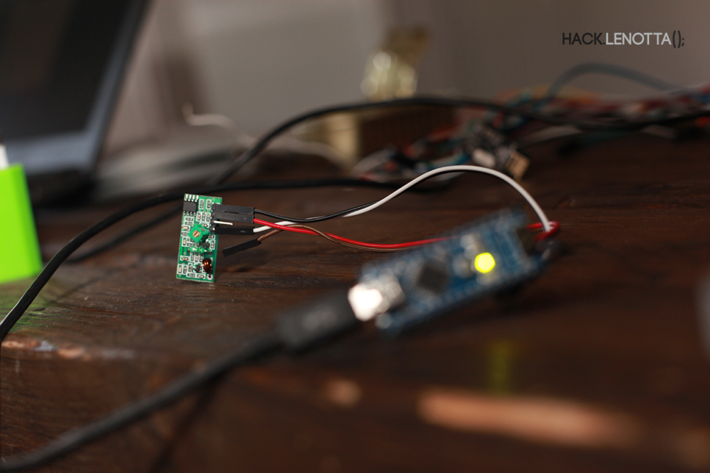
433MHz module attached to the Arduino
Recently it happened frequently that some of our friends needed to take their bikes inside our garden after a nerding night. It was a boring situation where we had to constantly find the remote, open the gate, wait for them to take their bikes and then open again. Well, it wasn’t so boring, but you know, we needed a reason.
So, we tought about our last project where we successfully made arduino talk with Raspy using NRF24L01+ and dumbly toggling lights. This time we decided to go a step further and open our gate using, guess what, our smartphones.
Learning
At first we tried to achieve our goal using the standard RCSwitch library (and sketches) to listen the original remote’s signal, but as you might imagined, we poorly failed.
The wiring was pretty simple:
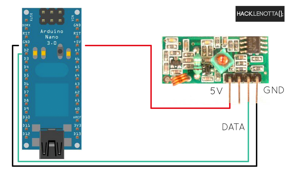
The Receiver wiring
Keeping in mind that we were working with a fixed combination remote, we initially guessed a number of different problematics, even that our receiver was not operating in the same frequency as the remote. After some attempts (where we’ve found the frequency was right by looking the quartz), we decided to hack a bit the original receiver sketch, forcing the arduino to receive the signals even if they were not conformed to the standard it used to know:
|
1 2 3 4 5 6 7 8 9 10 11 12 13 14 15 16 17 18 19 20 21 22 23 24 25 26 27 28 29 30 31 32 33 34 35 36 37 38 39 40 41 42 43 44 45 46 47 48 49 50 51 52 53 54 55 56 57 58 59 60 61 62 63 64 65 66 67 68 69 70 71 72 73 74 75 76 77 78 79 80 81 82 83 84 85 86 87 88 89 90 91 92 93 94 95 96 97 98 99 100 101 102 103 104 105 106 107 |
/* Example for receiving http://code.google.com/p/rc-switch/ If you want to visualize a telegram copy the raw data and paste it into http://test.sui.li/oszi/ Need help? http://forum.ardumote.com Edited by hack.lenotta to force it receive to ‘everything’ and included all the files at once. http://hack.lenotta.com */ #include <RCSwitch.h> // Format the output: void output(unsigned long decimal, unsigned int length, unsigned int delay, unsigned int* raw, unsigned int protocol) { if (decimal == 0) { Serial.print(«Unknown encoding.»); } else { char* b = dec2binWzerofill(decimal, length); Serial.print(«Decimal: «); Serial.print(decimal); Serial.print(» («); Serial.print( length ); Serial.print(«Bit) Binary: «); Serial.print( b ); Serial.print(» Tri-State: «); Serial.print( bin2tristate( b) ); Serial.print(» PulseLength: «); Serial.print(delay); Serial.print(» microseconds»); Serial.print(» Protocol: «); Serial.println(protocol); } Serial.print(«Raw data: «); for (int i=0; i<= length*2; i++) { Serial.print(raw[i]); Serial.print(«,»); } Serial.println(); Serial.println(); } static char* bin2tristate(char* bin) { char returnValue[50]; int pos = 0; int pos2 = 0; while (bin[pos] != ‘ ‘ && bin[pos+1] != ‘ ‘) { if (bin[pos]==‘0’ && bin[pos+1]==‘0’) { returnValue[pos2] = ‘0’; } else if (bin[pos]==‘1’ && bin[pos+1]==‘1’) { returnValue[pos2] = ‘1’; } else if (bin[pos]==‘0’ && bin[pos+1]==‘1’) { returnValue[pos2] = ‘F’; } else { return «not applicable»; } pos = pos+2; pos2++; } returnValue[pos2] = ‘ ‘; return returnValue; } // Make some conversions: static char * dec2binWzerofill(unsigned long Dec, unsigned int bitLength){ static char bin[64]; unsigned int i=0; while (Dec > 0) { bin[32+i++] = (Dec & 1 > 0) ? ‘1’ : ‘0’; Dec = Dec >> 1; } for (unsigned int j = 0; j< bitLength; j++) { if (j >= bitLength — i) { bin[j] = bin[ 31 + i — (j — (bitLength — i)) ]; }else { bin[j] = ‘0’; } } bin[bitLength] = ‘ ‘; return bin; } //The edited code to force recevining data: RCSwitch mySwitch = RCSwitch(); void setup() { Serial.begin(9600); mySwitch.enableReceive(0); // Receiver on inerrupt 0 => that is pin #2 } void loop() { output(mySwitch.getReceivedValue(), mySwitch.getReceivedBitlength(), mySwitch.getReceivedDelay(), mySwitch.getReceivedRawdata(),mySwitch.getReceivedProtocol()); mySwitch.resetAvailable(); } |
When we’ve uploaded the sketch we were able to see some raw messages. Actually, they were not messages, but these numbers on the serial monitor represent the interval between the changes of state (from 0 to 1 and reverse).
|
Unknown encoding.Raw data: 72, Unknown encoding.Raw data: 668, Unknown encoding.Raw data: 124, Unknown encoding.Raw data: 48, Unknown encoding.Raw data: 264, Unknown encoding.Raw data: 12, Unknown encoding.Raw data: 88 |
I suppose these numbers being just a representation of the signal noise. So, while listening with the arduino, we’ve pressed the button on the remote and BABOOM, here is what came out:
|
1 2 3 4 5 6 7 8 9 10 11 12 13 14 15 16 17 18 19 20 21 22 23 |
Unknown encoding.Raw data: 204, Unknown encoding.Raw data: 40, Unknown encoding.Raw data: 76, Unknown encoding.Raw data: 11660, Unknown encoding.Raw data: 11668, Unknown encoding.Raw data: 11672,328,648,324,316,668,316,656,644,324,316,660,316,668,316,656,320,652,652,324,652,328,652,320,648, Unknown encoding.Raw data: 11676,324,648,324,316,664,320,652,652,316,320,660,316,664,320,652,320,656,652,324,652,328,652,316,652, Unknown encoding.Raw data: 11676,324,648,324,316,664,320,652,652,316,320,660,316,664,320,652,320,656,652,320,656,324,652,320,652, Unknown encoding.Raw data: 11676,324,648,324,316,664,320,652,652,316,320,660,316,664,320,652,320,652,656,320,652,328,652,316,656, Unknown encoding.Raw data: 11676,324,648,324,316,664,320,652,652,316,320,660,320,660,320,652,320,656,652,320,656,328,652,316,656, Unknown encoding.Raw data: 11672,324,648,324,316,668,316,656,648,316,320,660,316,664,320,652,320,652,652,324,652,328,656,316,652, Unknown encoding.Raw data: 11672,324,652,320,320,664,316,656,648,320,320,660,320,664,316,656,320,656,652,320,656,324,652,316,652, |
A lot of very nice numbers… What helped a lot understand what was going on was the link in the arduino sketch which translate these numbers in a more understandable form (yes, it’s a squared wave):
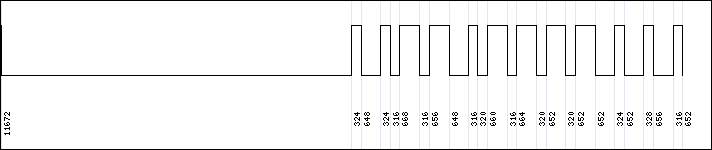
Squared wave
As you may noticed, the values (in microsecond), except for the first one being really long, are doubles of ~320 µs. I suggest to approximate the unit value (in our case 320 µs ) to the average of one interval, since the signal is surely disturbed by the uninsulated components of the arduino, and because of the usb cable, even by your bad boy computer.
Tuning and Speaking
Once we successfully received the message we had to send it back to the gate. We tried to use the message raughly received by the arduino, but we found out that we had to tune it a bit to make it work, maybe because of some latency or noise.
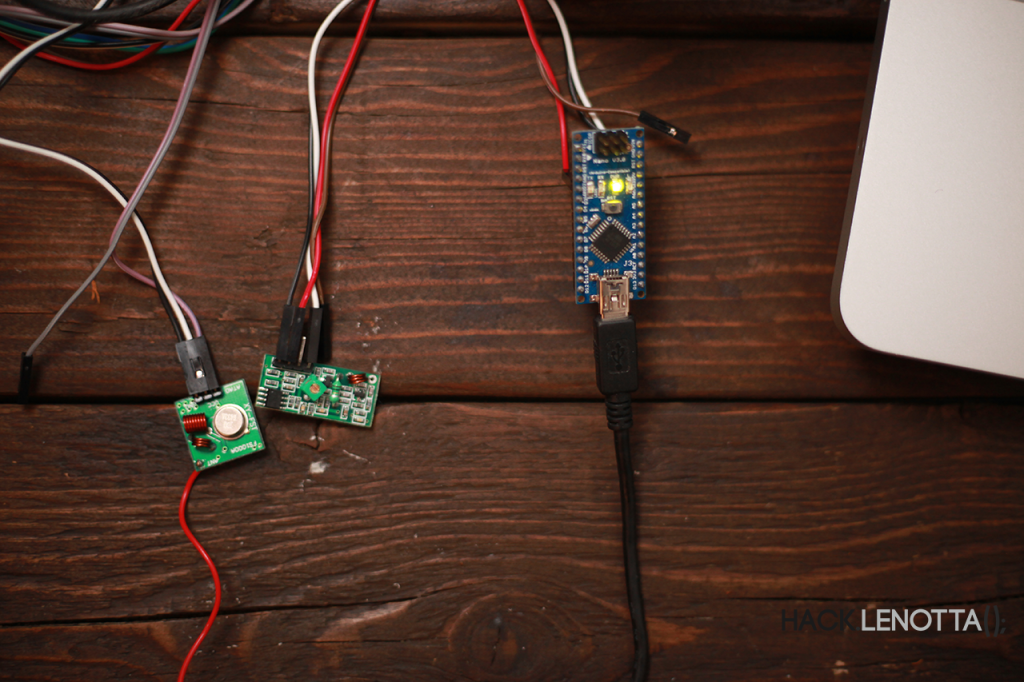
Try/Guess Environoment
We setted up a try/guess environment (pic above) with two arduinos, one with the 433 Mhz receiver we’ve setted up earlier and the other one with the twin transmitter module. We kept editing and sending the message untill we obtained the same message on the receiver as we were getting by the original remote.
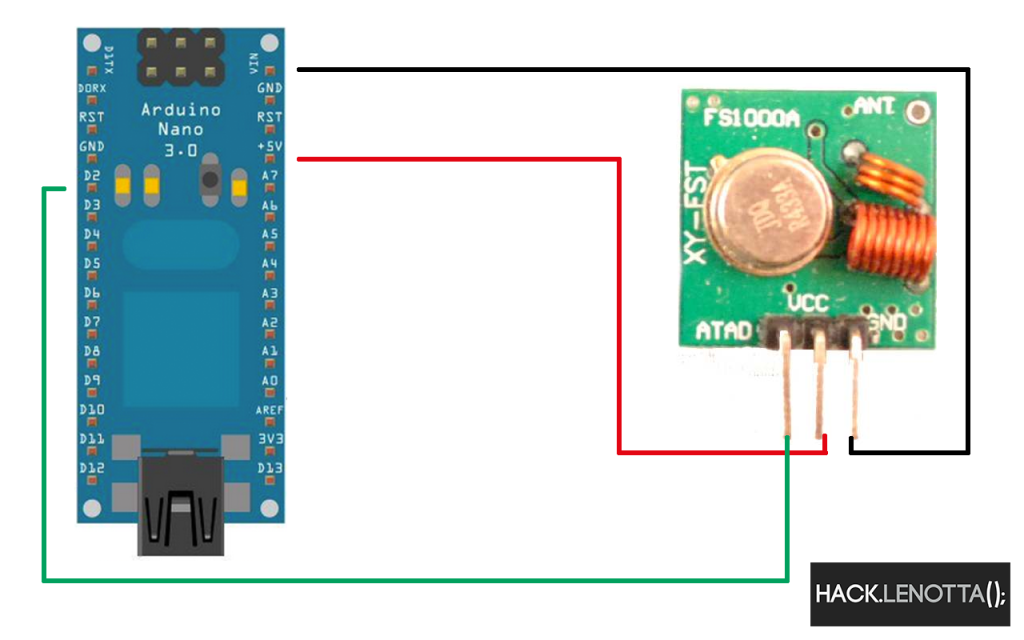
The Transmitter wiring
In this process we’ve found out two important fact:
1- The initial long length (11672 µs in our case) was received completely wrong, while the others were in the range of ±20
2- Our message was not completely transmitted (it was actually missing the last 3~4 intervals)
For the first problem we just tuned it easily with some tries, but the other was a little bit more complicated, which we roughly solved by sending multiple times the last intervals (if you have any better solution feel free to suggest!). Remember that to avoid misinterpretation by the gate receiver, the message has to be sent by the arduino at least 4 times.
Please note that some part of this sketch are taken from another sketch which we don’t remember where we took. If you are the author, please send us a mail with the link to your website and we’ll be glad to write your name and a backlink.
After all the final sketch resulted as following:
|
1 2 3 4 5 6 7 8 9 10 11 12 13 14 15 16 17 18 19 20 21 22 23 24 25 26 27 28 29 30 31 32 33 34 35 36 37 38 39 40 41 42 43 44 45 46 47 48 49 50 51 52 53 54 55 56 57 58 59 60 61 62 63 64 65 66 67 68 69 70 71 72 73 74 75 76 |
/* Transmitter opening fixed combination gates http://hack.lenotta.com CC-BY-SA */ int transmitPin = 2; void setup() { pinMode(transmitPin,OUTPUT); digitalWrite(transmitPin,LOW); } void loop() { turnOn(); } //let’s build our instruments: void customDelay(unsigned long time) { unsigned long end_time = micros() + time; while(micros() < end_time); } //1000=1ms void setStateWithDelay(int pin, int state,int delayTime) { if(state==1) digitalWrite(pin,HIGH); else digitalWrite(pin,LOW); customDelay(delayTime); } void turnOn() { setStateWithDelay(transmitPin,0,10972); setStateWithDelay(transmitPin,1,320); setStateWithDelay(transmitPin,0,630); setStateWithDelay(transmitPin,1,320); setStateWithDelay(transmitPin,0,320); setStateWithDelay(transmitPin,1,630); setStateWithDelay(transmitPin,0,320); setStateWithDelay(transmitPin,1,630); setStateWithDelay(transmitPin,0,630); setStateWithDelay(transmitPin,1,320); setStateWithDelay(transmitPin,0,320); setStateWithDelay(transmitPin,1,630); setStateWithDelay(transmitPin,0,320); setStateWithDelay(transmitPin,1,630); setStateWithDelay(transmitPin,0,320); setStateWithDelay(transmitPin,1,630); setStateWithDelay(transmitPin,0,320); setStateWithDelay(transmitPin,1,630); setStateWithDelay(transmitPin,0,630); setStateWithDelay(transmitPin,1,320); setStateWithDelay(transmitPin,0,630); setStateWithDelay(transmitPin,1,320); setStateWithDelay(transmitPin,0,630); setStateWithDelay(transmitPin,1,320); setStateWithDelay(transmitPin,0,630); setStateWithDelay(transmitPin,1,320); setStateWithDelay(transmitPin,0,630); digitalWrite(transmitPin,LOW); } |
Raspberry Integration
As I said at the beginning, the whole project was meant to give our friends access to their bike with their smartphones, so we decided to use the previous project we made about switching light using a node.js web app.
Sketching
The sketch is pretty easy and it’s a mix from the switching light post and the one we’ve used to open the gate:
|
1 2 3 4 5 6 7 8 9 10 11 12 13 14 15 16 17 18 19 20 21 22 23 24 25 26 27 28 29 30 31 32 33 34 35 36 37 38 39 40 41 42 43 44 45 46 47 48 49 50 51 52 53 54 55 56 57 58 59 60 61 62 63 64 65 66 67 68 69 70 71 72 73 74 75 76 77 78 79 80 81 82 83 84 85 86 87 88 89 90 91 92 93 94 95 96 97 98 99 100 101 102 103 104 105 106 107 108 109 110 111 112 113 114 115 116 117 118 119 120 121 122 123 124 125 126 127 128 129 130 131 132 133 134 135 136 137 138 139 140 141 142 143 144 145 146 147 148 149 150 151 152 153 154 |
/* Hack.lenotta.com Modified code of Getting Started RF24 Library It will open the gate if the message received is 2 Edo */ #include <SPI.h> #include «nRF24L01.h» #include «RF24.h» #include «printf.h» int transmitPin = 2; // // Hardware conf // // Set up nRF24L01 radio on SPI bus plus pins 9 & 10 RF24 radio(9,10); // // Topology // // Radio pipe addresses for the 2 nodes to communicate. const uint64_t pipes[2] = { 0xF0F0F0F0E1LL, 0xF0F0F0F0D2LL }; void setup(void) { // // Print preamble // Serial.begin(57600); pinMode(transmitPin,OUTPUT); digitalWrite(transmitPin,LOW); printf_begin(); printf(«nOpen Gate With Arduinonr»); // // Setup and configure rf radio // radio.begin(); radio.setRetries(15,15); radio.openWritingPipe(pipes[0]); radio.openReadingPipe(1,pipes[1]); radio.startListening(); radio.printDetails(); } void openGates(){ for (int i =0; i<20; i++){ gateCode(); } } void customDelay(unsigned long time) { unsigned long end_time = micros() + time; while(micros() < end_time); } //1000=1ms void setStateWithDelay(int pin, int state,int delayTime) { if(state==1) digitalWrite(pin,HIGH); else digitalWrite(pin,LOW); customDelay(delayTime); } void gateCode() { //your decodified gate code goes here, like the following: // setStateWithDelay(transmitPin,0,10972); // setStateWithDelay(transmitPin,1,320); // setStateWithDelay(transmitPin,0,630); // setStateWithDelay(transmitPin,1,320); // setStateWithDelay(transmitPin,0,320); // setStateWithDelay(transmitPin,1,630); // setStateWithDelay(transmitPin,0,320); // setStateWithDelay(transmitPin,1,630); // setStateWithDelay(transmitPin,0,630); // setStateWithDelay(transmitPin,1,320); // setStateWithDelay(transmitPin,0,320); // setStateWithDelay(transmitPin,1,630); // setStateWithDelay(transmitPin,0,320); // setStateWithDelay(transmitPin,1,630); // setStateWithDelay(transmitPin,0,320); // setStateWithDelay(transmitPin,1,630); // setStateWithDelay(transmitPin,0,320); // setStateWithDelay(transmitPin,1,630); // setStateWithDelay(transmitPin,0,630); // setStateWithDelay(transmitPin,1,320); // setStateWithDelay(transmitPin,0,630); // setStateWithDelay(transmitPin,1,320); // setStateWithDelay(transmitPin,0,630); // setStateWithDelay(transmitPin,1,320); // setStateWithDelay(transmitPin,0,630); // // setStateWithDelay(transmitPin,1,320); // setStateWithDelay(transmitPin,0,630); digitalWrite(transmitPin,LOW); } void loop(void) { // if there is data ready if ( radio.available() ) { // Dump the payloads until we’ve gotten everything unsigned long message; bool done = false; while (!done) { // Fetch the payload, and see if this was the last one. done = radio.read( &message, sizeof(unsigned long) ); if (message == 2){ openGates(); } // Delay just a little bit to let the other unit // make the transition to receiver delay(20); } // First, stop listening so we can talk radio.stopListening(); // Send the final one back. radio.write( &message, sizeof(unsigned long) ); printf(«Sent response.nr»); // Now, resume listening so we catch the next packets. radio.startListening(); } } |
Wiring
For the wirings, refer to the following picture:
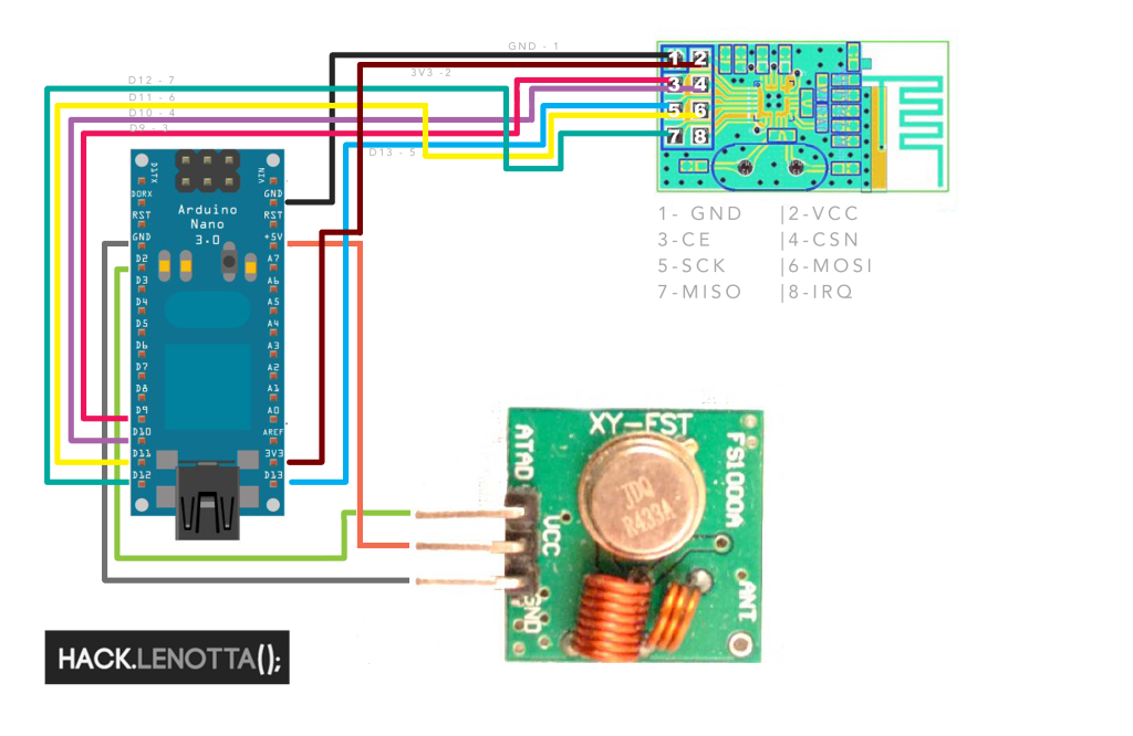
NRF24l01, Arduino and 433
Node application for Raspberry
Since we recently upgraded all the software, we could easily adapt our previous application to the new shiny remote. Here is the link to the Github repo.
To install it please follow the instruction on the switching light article, in particular the The Node.js Lamp Application section.
By continuing to use the site, or scrolling, you agree to the use of cookies. more information
The cookie settings on this website are set to «allow cookies» to give you the best browsing experience possible. If you continue to use this website without changing your cookie settings or you click «Accept» below then you are consenting to this.
Close