Содержание
- Посоветуйте, как добиться сходимости нелинейной задачи.
- Ansys Tips
- Search This Blog
- Defining Ansys Superelement SUB File Manually
- Newton-Raphson Residues
- Contact US
- Come Join Us!
- Posting Guidelines
- Related Projects
- New Ansys user — Unconverged Solution Problem
- New Ansys user — Unconverged Solution Problem
- New Ansys user — Unconverged Solution Problem
- RE: New Ansys user — Unconverged Solution Problem
- Red Flag Submitted
- Reply To This Thread
- Posting in the Eng-Tips forums is a member-only feature.
- Ползучесть горной породы (creep analysis in rock using Ansys Workbench 12.1 or 13)
Посоветуйте, как добиться сходимости нелинейной задачи.
14.08.2014, 12:54 #2
 14.08.2014, 13:52 #3
14.08.2014, 13:56 #4
14.08.2014, 14:31 #5
14.08.2014, 14:41 #6


14.08.2014, 14:59 #7
14.08.2014, 19:10 #8
15.08.2014, 09:13 #9
15.08.2014, 10:10 #10
15.08.2014, 11:04 #11
shell200 не существует. есть mesh200. это не расчетный элемент. но я думаю не в этом дело.
Попробуйте все-таки статику нелинейную.
И почитайте про transient анализ. Он бывает разных типов. Вы считаете методом суперпозиции, там есть ограничения. Попробуйте Full метод. Там дольше но все нелинейности поддерживаются.
15 мин. ——
Offtop: У Вас спросить не у кого, а беретесь за достаточно сложные вещи. На шапкозакидательство похоже.
15.08.2014, 12:12 #12
miko2009, спасибо, просматриваю solution information. В расчете используются элементы shell181, solid187.
Dron_629, и Вам спасибо. За опечатку прошу прощения, за нее неловко, мне известен этот тип элемента.
Статику запускала, не считает. Думаю побиться с ней.
Про анализ читала, но, конечно, не столько, сколько следует. Почитаю.
Offtop: Берусь не по собственной прихоти. Согласна, похоже, но так складывается.
15.08.2014, 17:24 #13
15.08.2014, 18:03 #14
bonded — это не контакт!
это СКЛЕИВАНИЕ поверхностей! (проще говоря уравнения связей — которые могут формироваться по умолчанию или задаваться принудительно)
no separation — это КОНТАКТ (весьма нефизичный с точки зрения здравого смысла вообще), НО — при частотном анализе у Вас будут решаться ЛИНЕЙНАЯ система уравнений.
а ЭТО ЗНАЧИТ — что ВСЕ нелинейности, в том числе и контакты буду в лучшем случае игнорироваться.
15.08.2014, 18:30 #15
15.08.2014, 18:34 #16
уф.
какой к черту метод?
Вы хотя бы документацию почитайте — прежде чем такие советы давать?
в документации к ЛЮБОЙ программе написано:
при определении собственных частот — ЛЮБЫЕ нелинейности программа «игнорирует» — это в лучшем случае.
почитайте теорию линейных уравнений?
при определении собственных частот решается система ЛИНЕЙНЫХ уравнений
а контакты — это нелинейность.
ну хоть чуть головой то подумайте?
Вы получаете собственные частоты «фиксированной» конструкции .
Какое Вы имеете право использовать эти частоты — по существу физические формы колебаний — если никакие контакты при их вычислении не учитывались.
Кроме того — с вероятностью 99% — данная конструкция геометрически нелинейная — а это АВТОМАТИЧЕСКИ исключает применение линейного решения — разложения по собственным формам!
Вашу задачу не стоит даже пытаться решать путем разложения по собственным частотам!
Вам скорее всего дали нагрузку в виде спектра ускорений из какого-то нормативного документа?!
если это так — то Вам нужно сгенерировать на основании этого спектра — какое-то полигармоническое нагружение — через обратное преобразование Фурье.
— единственный выход для Вас — это решать систему уравнения «в лоб» — используя либо обычную — неявную схему решения, если нагрузка длительная, либо явную — если нагрузка кратковременная или импульсная.
Далее — как моделировать саму задачу — т.е. какая постановка, зависит от жесткостей, от масс и их расположения, а так же от конструкции узлов крепления элементов друг с другом — т.е. это болты или это сварка или еще чего-то.
Кроме того — Вы вероятно еще сами для себя не сформулировали цели этого расчета — а это очень важно, ибо от этого так же зависит «технология» создания мат.модели, степень её детализации и пр.
Если будете использовать явный решатель — будьте осторожнее, ибо там шаг интегрирования очень мелкий и если Вы все шаги будете записывать — может просто не хватит места для записи.
Источник
Ansys Tips
and other thoughts.
Search This Blog
Defining Ansys Superelement SUB File Manually
Newton-Raphson Residues
When doing non-linear analysis, it is good practice to indicate you would like to save the Newton-Raphson Residuals before the analysis is started. It can go a long way in troubleshooting when/if the solution doesn’t converge later. You may do so by specifying how many youngest residuals you wish to keep. I personally like to keep 3 to see if it is consistent. Also, increase «Identify Element Violations» toggle to 1 to locate any mangled elements.
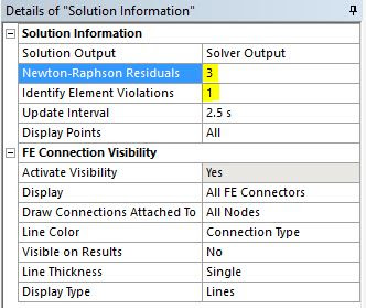
ANSYS now spends a bit of time & resource saving the residuals as it solves each iteration (see below). If you specify only 3 (as suggested above), only the youngest 3 residuals are saved with successive overwriting of the older files. The process is highlighted in the output file below:


The nd001_* are a selection of elements that are distorted. They are sometimes referred to as «Error in Element Formulation». In addition, the 3 Newton-Raphson Residual contour plots highlights the last three iteration’s out of balanced forces that are causing difficulties in convergence.
Now What?
These «hot spots» highlighted by the Newton-Raphson Residuals are the causing difficulty for convergence. Tweaking the mesh here may offer some relief. Or decrease the Normal Stiffness Factor of the contact in question to 0.01 if resultant penetration is allowed. Decreasing the initial step size may help. Making those few elements linear could be an option if that approximation is acceptable.
Источник
Thanks. We have received your request and will respond promptly.
Come Join Us!
- Talk With Other Members
- Be Notified Of Responses
To Your Posts - Keyword Search
- One-Click Access To Your
Favorite Forums - Automated Signatures
On Your Posts - Best Of All, It’s Free!
Posting Guidelines
Promoting, selling, recruiting, coursework and thesis posting is forbidden.
New Ansys user — Unconverged Solution Problem
New Ansys user — Unconverged Solution Problem
New Ansys user — Unconverged Solution Problem
Hi all, I’m a new member to the forum and I’ve lurked here for a while as I’ve found solutions to my previous issues deep within the forum. However, I have an issue with my current ANSYS problem (I’m also a rather green ANSYS user). I’m working in ANSYS APDL 14.0 with a 2D axisymmetric model.
I’m using Plane13 elements to represent magnetic coils that transfer load to a structure made of Plane82 elements. Everything is bonded, with no contact elements, mesh size is 1mm.
Since I’m relatively new to ANSYS in general I am having trouble figuring out how to solve this. Any help would be greatly appreciated.
I’m running into this convergence problem as stated by ANSYS:
RE: New Ansys user — Unconverged Solution Problem
I am using Ansys for structural problems, different from your field.
But about your problem, I think you should pay attention to the type of elements that you are using in the same model. Plane13 is a 4-node element while Plane82 has 8 nodes. How we can match 4 nodes to 8 nodes in boundaries? Also Plane82 has just 2-degrees of freedom in each node while it could be 4 degrees for the Plane13, in fact we can not match theses two elements in a common joint without coordinating DOFs. If you care about these matters, you may solve your problem.
Red Flag Submitted
Thank you for helping keep Eng-Tips Forums free from inappropriate posts.
The Eng-Tips staff will check this out and take appropriate action.
Reply To This Thread
Posting in the Eng-Tips forums is a member-only feature.
Click Here to join Eng-Tips and talk with other members! Already a Member? Login
Источник
Ползучесть горной породы (creep analysis in rock using Ansys Workbench 12.1 or 13)

Не могу решить проблему с ползучестью в Ansys Workbench 13.
Мне надо узнать как сильно горная порода имеющая соль (от этого на протяжении многих лет возникает ползучесть) деформирует в направление к отверстию шахты. Я разбила для начала задачу на два шага. Первый шаг – отключила ползучесть и установила время шага – 1Е-006 секунд. Все решается. Второй шаг – включила ползучесть и установила время шага – 1 год в секундах (мне надо в дальнейшем узнать деформацию ползучести через 75 лет, но пока я решила попробовать решить проблему на более маленький срок). Я разбила один год на более мелкие промежутки времени, чтобы улучшить конвергенцию, однако я получаю такие errors and warnings:
CREEP INTEGRATION ALGORITHM DID NOT CONVERGENCE FOR ELEMENET X…
REASON FOR TERMINATION…..ERROR IN ELEMENT FORMULATION
Кто -нибудь может посоветовать мне как решить эту проблему? Так как не понимаю в чем дело. Я улучшила сетку (mesh size and shape), но и это не помогает.
А какую модель ползучести вы используете? Есть вероятность, что не ту выбрали, вот и нет сходимости.
Я выбрала вторую модель – time hardening model , так как она мне больше всего подходит и я знаю константы (С1-С4)
Выложите на этот сайт в раздел «файлы», либо прямо сюда на форум архив вашего проекта, попытаюсь продиагностировать, в чём может быть проблема. Как архивировать, смотрите тут: http://www.cae-club.ru/content/arkhivirovanie-proekta-workbench
Спасибо,
Я выставила свой фаил. На данный момент это очень маленькая модель, но когда она заработает, мне надо построить шахту с настоящей геометрией в горной породе. Она будет растягиваться на глубину более одного километра от поверхности земли и будет будет отвечать соответствующему проекту и дизайну.
В моей модели сейчас это просто обычный диск (горная порода – Галит или еще ее называют каменная соль – Halite) с отверстием (это шахта) в середине на глубине 980-1030 метров).
Я поставила три нагрузки:
Первое – это давление земли сверху (pressure) на глубине 980 метров.
Второе – это гидростатическое давление (hydrostatic pressure) которое я поставила по периметру диска модели и использовала плотность каменной соли.
Третье – давление бетонного покрытия шахты – 1 мега паскаль – это максимум, так как если будет более 1 Мега Паскаль, то этот бетон начнет дробиться и раскалываться. Моя задача узнать насколько корная порода будет деформироваться в сторону отверстия на протяжение 1,3,5,10….и до 75 лет (это максимальный срок существования шахты) из за текучести присутствующей соли в породе.
У меня вопрос….две первые нагрузки, которые я приложила к этой модели (давление сверху и сбоку) должны по идее быть предсуществующими (они там были до бурения отверстия в этой горной породе). Мне волнует эффект деформации породы от проделывания отверстия шахты в земле (не зависит от времени – time independent) и потом ползучести (которая зависит от времени –time dependent). Может мне надо просто промоделировать кусок горной породы с существующими нагрузками , а потом уже сделать отверстие с бетонным покрытием? Так как когда я решаю эту модель до включения ползучести, мне кажется, эти нагрузки влияют на деформацию породы.
Дайте знать если Вам нужна еще какая то информация
Источник
3 февраля, 2020 — 00:04
#1
Здравствуйте! Прошу помощи! При моделировании железобетонного столба воспользовался моделью Вилама-Варнке (solid65), любезно описанной в видеоуроке CADFEM VL1502 — Моделирование железобетонных конструкций с помощью ANSYS Mechanical. Поменял геометрию, нагрузку и закрепления (использую «защемление» у основания — fixed support), в остальном аналогичный расчёт. При попытке провести расчёт Ansys доходит только до приготовления расчётной модели дальше расчёт обрывается и появляется ошибка «An unknown error occurred during solution. Check the Solver Output on the Solution Information object for possible causes.»
Посмотрел в Solution information, там вот следующие ошибки
*** NOTE ***                            CP =      64.125   TIME= 21:56:52
 The initial memory allocation (-m) has been exceeded.
  Supplemental memory allocations are being used.

 DISTRIBUTED SPARSE MATRIX DIRECT SOLVER.
  Number of equations =      869664,    Maximum wavefront =    162

 *** ERROR ***                           CP =      65.703   TIME= 21:57:08
 There is not enough memory for the Distributed Sparse Matrix Solver to
 proceed.  The Memory_Size value on the DSPOPTION command (30000 MB) is
 too large to be allocated on this system.  Please either decrease this
 Memory_Size value, or remove this field data from the DSPOPTION
 command completely, and rerun.

 *** ERROR ***                           CP =      65.703   TIME= 21:57:08
 An error has occurred in the Distributed Sparse Matrix Solver while
 attempting to allocate the memory required to process the matrix
 structure.  Error code = -2006.  Please send the data leading to this
 operation to your technical support provider, as this will allow
 ANSYS, Inc to improve the program.
Прошу, помогите, пожалуйста, чего программа от меня хочет? Больше памяти, или ошибка в другом?
Если требуется проект, то он в архиве (версия 17.2)
One of the problems we can encounter in a nonlinear
structural analysis in ANSYS Mechanical is that elements become so distorted
that the solver cannot continue. We get
messages saying the solver was unable to complete, and the solver output will
contain a message like this one:
*** ERROR ***                           CP =      37.969   TIME= 14:40:06
  Element 2988 (type = 1, SOLID187) (and maybe other elements) has become
  highly distorted.  Excessive distortion of elements is usually a
  symptom indicating the need for corrective action elsewhere.  Try
  incrementing the load more slowly (increase the number of substeps or
  decrease the time step size).  You may need to improve your mesh to
  obtain elements with better aspect ratios.  Also consider the behavior
  of materials, contact pairs, and/or constraint equations.  Please rule
  out other root causes of this failure before attempting rezoning or
  nonlinear adaptive solutions.  If this message appears in the first
  iteration of first substep, be sure to perform element shape checking.
The Solution branch will have the telltale red lightning
bolts, indicating the solution was not able to complete due to nonconvergence.
If you are not aware, one technique we can use to get past
this problem of excessive element distortion is to have ANSYS automatically
remesh the model or a portion of the model while the solution is
progressing. The current state of the
model is then mapped onto the new mesh, in the currently deflected state. In this manner we can automatically continue
with the solution after a slight pause for this remeshing to occur. Minimally all we need to do as users is
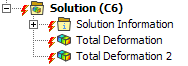
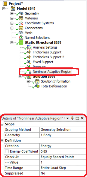
insert a Nonlinear Adaptive Region under the Static Structural branch, and
review and specify a few settings (more on this later).
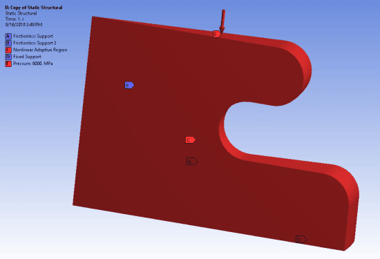
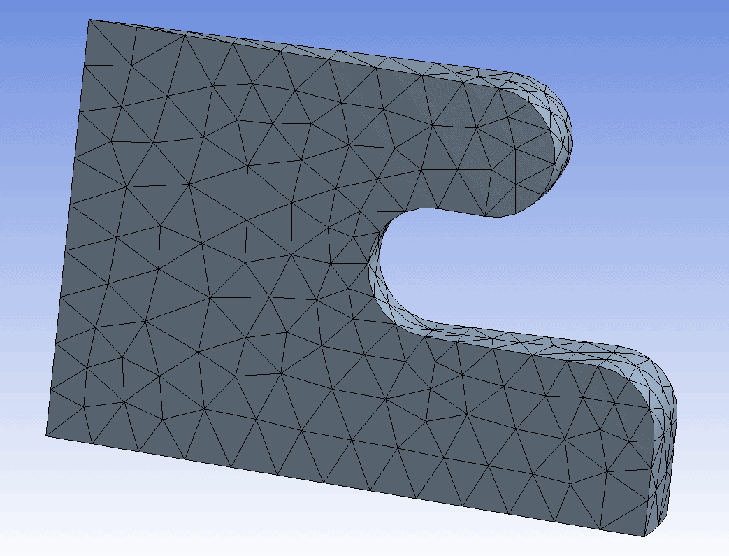
Let’s take a look at a simple example. This is a wedge portion of a circular
hyperelastic part, subject to a pressure load on the top surface. Other boundary conditions include a fixed
support on the bottom and frictionless supports on the two cut faces of the
wedge.
For this case, the nonlinear adaptive region is the entire
part.
The initial mesh was setup as a default mesh, although note
that for 3D models the nonlinear adaptive capability requires a tetrahedral
mesh up through the current version, 2019 R2.
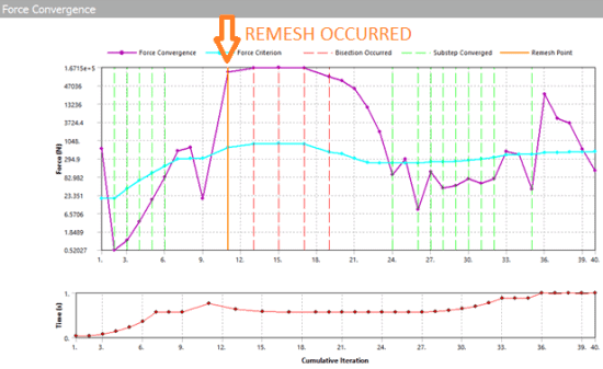
Prior to solving with the nonlinear adaptive region
included, this model fails to converge at about 56% of the total load. With the addition of the nonlinear adaptive
region, the model is automatically remeshed at the point of excessive element
distortion, and the solution is able to proceed until the full load is applied. The force convergence graph has a solid
vertical orange line at the point where remeshing occurred. The method can result in multiple remeshing
steps although in the sample model shown here, only one remeshing was needed.
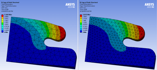
The image on the left, below, shows the original mesh at the
last converged substep before remeshing occurred. The image on the right is the first result
set after remeshing was completed.
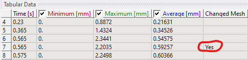
The tabular view of a result item will show in the last
column if remeshing has occurred during the solution.
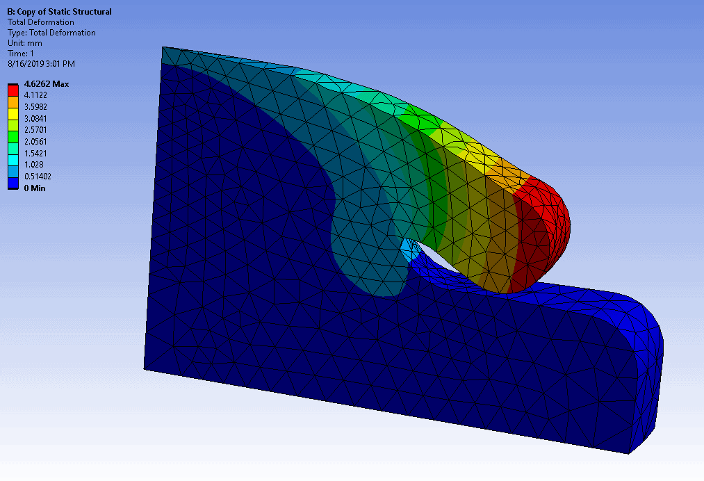
Here is the final deformation, for the full amount of
pressure load applied on the top surface.
Next, let’s take a look at the nonlinear adaptive region
capability in more detail.
First, multiple substeps must be used for the solution. If we are performing a nonlinear analysis,
this will be the case anyway. Second,
Large Deflection needs to be turned on in the Analysis Settings branch. Also, results must be stored at all time
points (note that time is a tracking parameter in a static analysis, but all
static as well as transient results in ANSYS Mechanical are associated with a
value of ‘time’).
There are several restrictions on features that CAN’T be in
the model, such as cyclic symmetry (hence the frictionless support BC’s on the
simple model shown above), Auto Asymmetric Contact, Joints, Springs, Remote
Forces and Displacements, etc. Also
certain material properties are excluded, such as Cast Iron plasticity and
Shape Memory Alloy. Also, as mentioned
above, for 3D models, the mesh must be tetrahedral. For a full listing of these restrictions,
refer to the ANSYS Mechanical User’s Guide.
A search on ‘nonlinear adaptive’ will take you to the right location in
the Help.
Nonlinear Adaptive Regions can be scoped to 3D solid and 2D
bodies, or to elements via a Named Selection.
In the Details view for the Nonlinear Adaptive Region, the
main option to be defined is the Criterion by which remeshing will be
initiated. There are three options
available in Mechanical: Energy, Box,
and Mesh.
The Energy criterion checks the strain energy of each
element within the Nonlinear Adaptive Region.
If the strain energy is above a criterion, remeshing is triggered. The input is an energy coefficient between
zero and one, and is a multiplier on the ratio of total strain energy of the
component divided by the number of elements of the component. Recommended values are 0.85-0.9. A lower coefficient will tend to cause
remeshing to be more likely.
The Box criterion defines a geometry region based on a
coordinate system and bounds relative to that coordinate system. Elements in the Nonlinear Adaptive Region
whose nodes have all moved within the box will be remeshed. The idea is that if it’s known that elements
will be highly distorted as they move into a certain region, we can ensure that
remeshing will occur there.
The Mesh criterion allows us to specify that remeshing will
occur if mesh quality measures drop below certain levels as the mesh
distorts. For 3D models, the available
measures are Jacobian Ratio and Skewness.
These are described in the Mechanical User’s Guide in the section on
Nonlinear Adaptive Region.
In the example shown above, the Energy criterion was used
with an energy coefficient of 0.85.
There are some things to be aware of when you are trying to
implement a Nonlinear Adaptive Region to help overcome convergence
difficulties. First, if any of the
restricted features mentioned above are included in the model, such as remote
displacements, it’s not going to work.
Therefore, it’s important to review the list of restrictions in the Help
and make sure none of those are applied in your model. Second, ‘buckling’ or element distortion due
to an unstable structure is not a behavior that Nonlinear Adaptive Regions can
help with. The Nonlinear Adaptive Region
capability is more suited to problems like hyperelastic seals being compressed
or objects that are undergoing a high degree of bending (but not snapping
through).
Also, a coarse mesh that distorts may not produce a usable
remesh. The remeshing step may occur,
but the simulation may not be able to proceed beyond that and stops with an
error in element formulation error. More
mesh refinement may be needed in this case.
As a further word of caution, self contact problems may not
work very well within the context of Nonlinear Adaptive Regions. If self contact is needed, consider splitting
the bodies into multiple parts to avoid self contact.
There are some other considerations for the method as
discussed in the Help, but hopefully the guidelines and recommendations
presented here will allow you to filter potential applications appropriately
and setup models that can take advantage of the Nonlinear Adaptive Region
capability. We have a short animation
which shows the remeshing step in the sample model.
If you have nonlinear static structural models with convergence difficulties due to excessive element distortion, please consider using this method to help you get a fully converged solution.
Here is a video to help everyone visualize:
As this video shows, adaptive meshing is a game changer for many complex large deflection problems and has opened a whole new category of simulation that can be done in Ansys Mechanical.
INTELLIGENT WORK FORUMS
FOR ENGINEERING PROFESSIONALS
Contact US
Thanks. We have received your request and will respond promptly.
Log In
Come Join Us!
Are you an
Engineering professional?
Join Eng-Tips Forums!
- Talk With Other Members
- Be Notified Of Responses
To Your Posts - Keyword Search
- One-Click Access To Your
Favorite Forums - Automated Signatures
On Your Posts - Best Of All, It’s Free!
*Eng-Tips’s functionality depends on members receiving e-mail. By joining you are opting in to receive e-mail.
Posting Guidelines
Promoting, selling, recruiting, coursework and thesis posting is forbidden.
Students Click Here
error in element formulationerror in element formulation(OP) 22 Jan 10 13:16 Hi thanks for the answer Ii´m ussing : Material: Master /node : Red Flag SubmittedThank you for helping keep Eng-Tips Forums free from inappropriate posts. |
Resources
Learn methods and guidelines for using stereolithography (SLA) 3D printed molds in the injection molding process to lower costs and lead time. Discover how this hybrid manufacturing process enables on-demand mold fabrication to quickly produce small batches of thermoplastic parts. Download Now
Examine how the principles of DfAM upend many of the long-standing rules around manufacturability — allowing engineers and designers to place a part’s function at the center of their design considerations. Download Now
Metal 3D printing has rapidly emerged as a key technology in modern design and manufacturing, so it’s critical educational institutions include it in their curricula to avoid leaving students at a disadvantage as they enter the workforce. Download Now
This ebook covers tips for creating and managing workflows, security best practices and protection of intellectual property, Cloud vs. on-premise software solutions, CAD file management, compliance, and more. Download Now |


Join Eng-Tips® Today!
Join your peers on the Internet’s largest technical engineering professional community.
It’s easy to join and it’s free.
Here’s Why Members Love Eng-Tips Forums:
 Talk To Other Members
- Notification Of Responses To Questions
- Favorite Forums One Click Access
- Keyword Search Of All Posts, And More…
 Talk To Other Members
Register now while it’s still free!
Already a member? Close this window and log in.
Join Us Close
Добрый вечер, техники и механики.
Возникла необходимость считать диссипацию энергии колеблющейся системы в контактной паре. Пока, решил научиться просто решать контакт. Взял простую задачу брусочек по брусочку. В статике все хорошо — задача сходится. Но в дальнейшем необходимо будет смотреть отклик колеблющейся системы, то есть возбуждать импульсным воздействием, а затем проводить Фурье анализ для определения собственных частот и амплитуд различных форм колебания. Вот и пытаюсь посчитать теперь эту задачу в транзиенте, чтобы убедиться что все работает и потом уже переходить на реальную конструкцию. Но когда я считаю промежуток в 1 секунду скольжения с шагом 0.01 — на 24 шаге, после смещения верхнего бруска на 4,8 мм устойчивость схемы теряется и расчет расходится. Ошибка «ERROR IN ELEMENT FORMULATION». У меня вопрос, неужели это контактный элемент эррорится? Как исключить возможность данной ошибки и добиться устойчивого сходящегося решения?
ниже привожу ЛОГ файл задачи с брикетами. заранее спасибо, тем кто откликнется)
Код:
/COM,ANSYS RELEASE 11.0SP1 UP20070830 13:56:04 06/24/2011
/input,menust,tmp,»,,,,,,,,,,,,,,,,1
/GRA,POWER
/GST,ON
/PLO,INFO,3
/GRO,CURL,ON
/CPLANE,1
/REPLOT,RESIZE
WPSTYLE,,,,,,,,0
/COM, Structural
FINISH
/PREP7
!*
ET,1,SOLID186
!*
ET,2,TARGE170
!*
ET,3,CONTA174
!*
!*
MPTEMP,,,,,,,,
MPTEMP,1,0
MPDATA,EX,1,,2000
MPDATA,PRXY,1,,0.3
MPTEMP,,,,,,,,
MPTEMP,1,0
MPDATA,EX,2,,2e12
MPDATA,PRXY,2,,0.3
BLOCK,0,4,0,1,0,0.5,
BLOCK,0,1,0,1,0.5,1,
BLOCK,3.5,4,0,1,0.5,1,
!!!! МЕШИНГ ДВИЖУЩЕЙСЯ ЧАСТИ И ДЛИННОЙ СТАТИЧЕСКОЙ ПОВЕРХНОСТИ
CM,_Y,VOLU
VSEL, , , , 1
CM,_Y1,VOLU
CMSEL,S,_Y
!*
CMSEL,S,_Y1
VATT, 1, , 1, 0
CMSEL,S,_Y
CMDELE,_Y
CMDELE,_Y1
!*
CM,_Y,VOLU
VSEL, , , , 2
CM,_Y1,VOLU
CMSEL,S,_Y
!*
CMSEL,S,_Y1
VATT, 2, , 1, 0
CMSEL,S,_Y
CMDELE,_Y
CMDELE,_Y1
!*
!!!!
ESIZE,0.1,0, ! elemetn size
FLST,5,2,6,ORDE,2
FITEM,5,1 ! volume 1 medium
FITEM,5,2 ! and volume 2 long
CM,_Y,VOLU
VSEL, , , ,P51X
CM,_Y1,VOLU
CHKMSH,’VOLU’
CMSEL,S,_Y
!*
MSHAPE,0,3d
MSHKEY,1
VMESH,_Y1
MSHKEY,0
!*
CMDELE,_Y
CMDELE,_Y1
CMDELE,_Y2
!*
!!!! МЕШИНГ МАЛЕНЬКОГО «УПОРА» — тормозного башмака=)
ESIZE,0.1,0,
MSHKEY,1
!*
CM,_Y,VOLU
VSEL, , , , 3
CM,_Y1,VOLU
CHKMSH,’VOLU’
CMSEL,S,_Y
!*
VMESH,_Y1
!*
CMDELE,_Y
CMDELE,_Y1
CMDELE,_Y2
!*
!!!!! Displacement LOADS
FLST,2,1,5,ORDE,1 ! основание
FITEM,2,1
!*
/GO
DA,P51X,ALL,0 !!! dof = 0
FLST,2,6,5,ORDE,4 ! все сотальное
FITEM,2,3
FITEM,2,-6
FITEM,2,15
FITEM,2,-16
!*
/GO
DA,P51X,ALL,0 !!! dof = 0
!*
KEYOPT,2,1,1
KEYOPT,2,2,0
KEYOPT,2,3,0
!*
KEYOPT,2,4,0
KEYOPT,2,5,0
!*
KEYOPT,3,1,0
KEYOPT,3,2,1
KEYOPT,3,4,0
KEYOPT,3,5,0
KEYOPT,3,6,0
KEYOPT,3,7,0
KEYOPT,3,8,2
KEYOPT,3,9,0
KEYOPT,3,10,0
KEYOPT,3,11,0
KEYOPT,3,12,0
!*
/MREP,EPLOT
!!!! СОЗДАНИЕ КОНТАКТНОЙ ПАРЫ
/COM, CONTACT PAIR CREATION — START
CM,_NODECM,NODE
CM,_ELEMCM,ELEM
CM,_KPCM,KP
CM,_LINECM,LINE
CM,_AREACM,AREA
CM,_VOLUCM,VOLU
/GSAV,cwz,gsav,,temp
MP,MU,1,0.12
MAT,1
MP,EMIS,1,7.88860905221e-031
R,3
REAL,3
ET,4,170
ET,5,174
R,3,,,1.0,0.1,0,
RMORE,,,0.07,0.0,1.0,
RMORE,0,0,1.0,,1.0,0.5
RMORE,0,1.0,1.2,0.0,,1.0
KEYOPT,5,4,0
KEYOPT,5,5,0
KEYOPT,5,7,0
KEYOPT,5,8,0
KEYOPT,5,9,0
KEYOPT,5,10,2
KEYOPT,5,11,0
KEYOPT,5,12,0
KEYOPT,5,2,0
KEYOPT,4,5,0
! Generate the target surface
ASEL,S,,,2
CM,_TARGET,AREA
TYPE,4
NSLA,S,1
ESLN,S,0
ESLL,U
ESEL,U,ENAME,,188,189
NSLE,A,CT2 ! CZMESH patch (fsk qt-40109 8/2008)
ESURF
CMSEL,S,_ELEMCM
! Generate the contact surface
ASEL,S,,,7
CM,_CONTACT,AREA
TYPE,5
NSLA,S,1
ESLN,S,0
NSLE,A,CT2 ! CZMESH patch (fsk qt-40109 8/2008)
ESURF
ALLSEL
ESEL,ALL
ESEL,S,TYPE,,4
ESEL,A,TYPE,,5
ESEL,R,REAL,,3
/PSYMB,ESYS,1
/PNUM,TYPE,1
/NUM,1
EPLOT
ESEL,ALL
ESEL,S,TYPE,,4
ESEL,A,TYPE,,5
ESEL,R,REAL,,3
CMSEL,A,_NODECM
CMDEL,_NODECM
CMSEL,A,_ELEMCM
CMDEL,_ELEMCM
CMSEL,S,_KPCM
CMDEL,_KPCM
CMSEL,S,_LINECM
CMDEL,_LINECM
CMSEL,S,_AREACM
CMDEL,_AREACM
CMSEL,S,_VOLUCM
CMDEL,_VOLUCM
/GRES,cwz,gsav
CMDEL,_TARGET
CMDEL,_CONTACT
/COM, CONTACT PAIR CREATION — END
/MREP,EPLOT
/COM, CONTACT PAIR PROPERTIES — START
MP,MU,1,0.12
RMODIF,3,9,0.07
RMODIF,3,21,1.4
RMODIF,3,22,100
KEYOPT,5,2,1
/COM, CONTACT PAIR PROPERTIES — END
NROPT,UNSYM
/MREP,EPLOT
/REPLOT
FLST,2,1,5,ORDE,1
FITEM,2,8
/GO
!*
SFA,P51X,1,PRES,2 ! вертикальная «прижимающая» составляющая нагрузки на движущийся брусок
FLST,2,1,5,ORDE,1
FITEM,2,11
/GO
FLST,2,1,5,ORDE,1
FITEM,2,11
/GO
!*
SFA,P51X,1,PRES,0.6 ! Горизонтальная составляющая нагрузки на движущийся брусок
!*
ANTYPE,4
!*
TRNOPT,FULL
LUMPM,1
!*
FINISH
!!!! РЕШАЛКА
/SOL
ANTYPE,4
NLGEOM,1
DELTIM,0.01,0,0
OUTRES,ERASE
OUTRES,ALL,ALL
AUTOTS,0
NCNV,2,0,0,0,0
TIME,1