This topic has been deleted. Only users with topic management privileges can see it.
Hello.
Yesterday when I tried to print from SD card, suddenly the light of the wifi module started to blink very fast.
After that I appeared that the wifi module doesn’t work.
I have once Erased the Firmware from the board and re-installed.
The version is 2.05.1.
Then I sent M552 S1 and M587 S»ooxx» P»ooxx»
Unfortuantely the error «M587:Failed to add SSID to remembered list.» came back.
I have sent only M587.
Then I see, «Failed to retrieve network list»
Maybe the wifi module has got a problem ???
Please help!
@Hiroaki Connect via USB, send M552 S-1 to turn WiFi off, then M552 S0 to turn it on, but in idle mode, then add the SSID with M587. Finally, enable WiFi with M552 S1.
Ian
@jay_s_uk Hello Thank you for your comment.
I have done it, but still the same…
@droftarts Hello. Thank you for your comment, I did it.
When I send M552 S-1, the light of the wifi module was turned off.
When I sent M552 S0, it’s turned on again.
But when I sent M587 S»ooxx» P»ooxx» it’s still the same…
Only One I can’t get is «Idle mode» I put….
@Hiroaki Sorry «Idle mode» you put.
@Hiroaki Can you send M122 and post full reply. How old is the Duet?
And what board revision? eg 1.02, 1.04c
Ian
@droftarts
Hello The board is quite new.
I bought it about two months ago, but as I have been building the machine, it’s still like new.
The answer of M122 is as floows. Thank you.
=== Diagnostics ===<LF>RepRapFirmware for Duet 2 WiFi/Ethernet version 2.05.1 running on Duet WiFi 1.02 or later + DueX5<LF>Board ID: 08DJM-956GL-M43T0-6JKDL-3S86P-994YQ<LF>Used output buffers: 1 of 24 (2 max)<LF>=== RTOS ===<LF>Static ram: 25712<LF>Dynamic ram: 93980 of which 84 recycled<LF>Exception stack ram used: 264<LF>Never used ram: 11032<LF>Tasks: NETWORK(ready,1884) HEAT(blocked,1232) DUEX(suspended,160) MAIN(running,3824) IDLE(ready,160)<LF>Owned mutexes:<LF>=== Platform ===<LF>Last reset 00:00:14 ago, cause: power up<LF>Last software reset time unknown, reason: User, spinning module GCodes, available RAM 10896 bytes (slot 2)<LF>Software reset code 0x0003 HFSR 0x00000000 CFSR 0x00000000 ICSR 0x0441f000 BFAR 0xe000ed38 SP 0xffffffff Task 0x4e49414d<LF>Error status: 0<LF>Free file entries: 10<LF>SD card 0 detected, interface speed: 20.0MBytes/sec<LF>SD card longest block write time: 0.0ms, max retries 0<LF>MCU temperature: min 50.4, current 52.0, max 56.3<LF>Supply voltage: min 0.5, current 0.5, max 0.8, under voltage events: 0, over vol[Warning: Maximal number of bytes per line exceeded! Check the EOL (end-of-line) settings or increase the limit in the advanced terminal settings.]
@Hiroaki The version is 1.04.
@Hiroaki The M122 reply has been cut off, and the WiFi diagnostics is missing. If you are connecting with YAT:
Set YAT to use <LF> as the end of line character. This will improve the readability of the messages coming from the Duet. Click «Text Settings» in the «Terminal Settings» and change «EOL sequence:» to <LF>. Click «OK» to close Text Settings. Click «OK» again to close Terminal Settings.
Ian
@droftarts Thank you.
This is it.
=== Diagnostics ===
RepRapFirmware for Duet 2 WiFi/Ethernet version 2.05.1 running on Duet WiFi 1.02 or later + DueX5
Board ID: 08DJM-956GL-M43T0-6JKDL-3S86P-994YQ
Used output buffers: 1 of 24 (2 max)
=== RTOS ===
Static ram: 25712
Dynamic ram: 93980 of which 84 recycled
Exception stack ram used: 264
Never used ram: 11032
Tasks: NETWORK(ready,1884) HEAT(blocked,1232) DUEX(suspended,160) MAIN(running,3836) IDLE(ready,160)
Owned mutexes:
=== Platform ===
Last reset 00:06:48 ago, cause: power up
Last software reset time unknown, reason: User, spinning module GCodes, available RAM 10896 bytes (slot 2)
Software reset code 0x0003 HFSR 0x00000000 CFSR 0x00000000 ICSR 0x0441f000 BFAR 0xe000ed38 SP 0xffffffff Task 0x4e49414d
Error status: 0
Free file entries: 10
SD card 0 detected, interface speed: 20.0MBytes/sec
SD card longest block write time: 0.0ms, max retries 0
MCU temperature: min 29.5, current 32.0, max 65.8
Supply voltage: min 0.0, current 0.5, max 0.6, under voltage events: 0, over voltage events: 0, power good: no
Driver 0: ok, SG min/max not available
Driver 1: ok, SG min/max not available
Driver 2: ok, SG min/max not available
Driver 3: ok, SG min/max not available
Driver 4: ok, SG min/max not available
Driver 5: ok, SG min/max not available
Driver 6: ok, SG min/max not available
Driver 7: ok, SG min/max not available
Driver 8: ok, SG min/max not available
Driver 9: ok, SG min/max not available
Date/time: 1970-01-01 00:00:00
Cache data hit count 681994076
Slowest loop: 1.58ms; fastest: 0.05ms
I2C nak errors 0, send timeouts 0, receive timeouts 0, finishTimeouts 0, resets 0
=== Move ===
Hiccups: 0, FreeDm: 160, MinFreeDm: 160, MaxWait: 0ms
Bed compensation in use: none, comp offset 0.000
=== DDARing ===
Scheduled moves: 0, completed moves: 0, StepErrors: 0, LaErrors: 0, Underruns: 0, 0
=== Heat ===
Bed heaters = 0 -1 -1 -1, chamberHeaters = -1 -1
Heater 1 is on, I-accum = 0.0
=== GCodes ===
Segments left: 0
Stack records: 1 allocated, 0 in use
Movement lock held by null
http is idle in state(s) 0
telnet is idle in state(s) 0
file is idle in state(s) 0
serial is ready with «M122» in state(s) 0
aux is idle in state(s) 0
daemon is idle in state(s) 0
queue is idle in state(s) 0
autopause is idle in state(s) 0
Code queue is empty.
=== Network ===
Slowest loop: 0.84ms; fastest: 0.00ms
Responder states: HTTP(0) HTTP(0) HTTP(0) HTTP(0) FTP(0) Telnet(0) Telnet(0)
HTTP sessions: 0 of 8
- WiFi —
Network state is starting
WiFi module is disabled
Failed messages: pending 0, notready 0, noresp 0
Socket states: 0 0 0 0 0 0 0 0
ok
@droftarts
M552 s-1
WiFi module stopped
ok
M552 s0
ok
M122
then it was still
- WiFi —
Network state is starting
WiFi module is disabled
Failed messages: pending 0, notready 0, noresp 0
Socket states: 0 0 0 0 0 0 0 0
ok
@Hiroaki Send M552 S-1, then M122, M552 S0, then M122, and M552 S1, then M122. This is what the response from my Duet 2 WiFi looks like (you can just copy the WiFi part at the end):
M552 S-1
WiFi module stopped
ok
M122
=== Diagnostics ===
RepRapFirmware for Duet 2 WiFi/Ethernet version 2.05 running on Duet WiFi 1.02 or later
Board ID: 08DGM-9T6BU-FG3SD-6JKD4-3S86N-KAMHF
…
-WiFi —
Network state is disabled
WiFi module is disabled
Failed messages: pending 0, notready 0, noresp 0
Socket states: 0 0 0 0 0 0 0 0
ok
M552 S0
ok
WiFi module started
M122
…
-WiFi —
Network state is running
WiFi module is idle
Failed messages: pending 0, notready 0, noresp 0
WiFi firmware version 1.23
WiFi MAC address a0:20:a6:31:b4:b9
WiFi Vcc 3.36, reset reason Turned on by main processor
WiFi flash size 4194304, free heap 30176
Socket states: 0 0 0 0 0 0 0 0
ok
M552 S1
ok
WiFi module is connected to access point BTWholeHome-XXX, IP address 192.168.0.12
M122
…
-WiFi —
Network state is running
WiFi module is connected to access point
Failed messages: pending 0, notready 0, noresp 0
WiFi firmware version 1.23
WiFi MAC address a0:20:a6:31:b4:b9
WiFi Vcc 3.37, reset reason Turned on by main processor
WiFi flash size 4194304, free heap 25568
WiFi IP address 192.168.0.12
WiFi signal strength -43dBm, reconnections 0, sleep mode modem
Socket states: 0 0 0 0 0 0 0 0
ok
If you’re not getting something similar, I’d guess that the WiFi module has failed. The usual reason for this is a power surge on the 3.3V line; the WiFi board and SD card are often the first to fail if this has happened, but can protect the main processor from failing.
It is possible that the WiFi module firmware has not flashed correctly. Try downloading a fresh DuetWiFiServer-1.23.bin from https://github.com/Duet3D/RepRapFirmware/releases/tag/2.05.1 and upload it to the ‘sys’ folder on the SD card, then send M997 S1.
Ian
Hello @Hiroaki… I have had this issue myself a few times. The advice here did solve it; but I had to do it a couple of times. Re-flashing the firmware more than once might be necessary. I also found that in BOSSA, using the setting «erase all» seemed to yield the best results. Good luck to you!
@droftarts Thank you. As it’s getting late night, I will do it tomorrow.
By the way do you think it’s possible to change the wifi module ?
@beachtec Thank you. I will try tomorrow. It’s 0:21AM …
Best Regards
@droftarts
One question .
Upload Duetwifiserver-1.23.bin to the SYS not WWW folder?
Regards
@Hiroaki said in Error M587:Failed to add SSID to remembered list.:
One question .
Upload Duetwifiserver-1.23.bin to the SYS not WWW folder?
Yes, firmware updates go in the ‘sys’ folder. The ‘www’ folder is for DWC components.
Ian
DuetWiFiServer-1.23.bin
I think you’ll need to rename the file and remove the -1.23 part so that the final file name is just DuetWiFiServer.bin
@droftarts Hello
Thank you so much.
I could solve the problem.
sent M997 S1 and then ok.
I appreciate that.
Thank you
@Phaedrux Thank you.
This was also helped me !
Thank you.
Zheka1980

Загрузка
05.12.2021
938
Плата Octopus BTT 1.1
Прошивка RepRap 3.3
Модуль WiFi — от покупавшейся 4 года назад MKS RObin (даже на плате написано RObin). Но, я проверял, распиновка соответствует тому, что на плате Octopus.
Набираю в консоли
M552 S0
M587 S»TP-Link_AB59_5G» P»XXXXXXXX»
Получаю:
Error: M587: Failed to add SSID to remembered list: another SPI transfer is pending
Диод на модуле не мигает.
Что делать и кто виноват?
Ответы на вопросы
Популярные вопросы
Держатель катушки филамента.
vadimxg
Загрузка
20.01.2023
1224
Ребята, привет!
Какая самая удобная на ваш взгляд модель держателя катушки филамента? Можете ссылку на самую удобную модель показать?…
Про термистор RTD PT 1000B
Ertil
Загрузка
15.01.2023
795
Добрый день, уважаемые коллеги. По велению собственных «хотелок», приобрёл керамический нагревательный элемент от TriangleLab, CHC KIT PT1…
помогите выбрать 3Д принтер
serz55
Загрузка
19.08.2018
8958
нашел четыре недорогих принтера. по описанию только на АНЕТ А6 много инфы а вот на остольные н
почти нету! подскажите какой из переч…
Читайте в блогах
Introduction
Please read before proceeding to avoid damaging the controller and voiding your warranty
- Avoid connecting the Controller via USB when you do not need to. (Except when instructed to in the guides)
- Always unplug the WorkBee Power Supply before connecting the USB Cable.
-


-
The WiFi module only supports 2.4Ghz networks. 5Ghz is not supported.
-
For Mac users, at certain points in these instructions, you will need to use double quotation marks in commands. Any double quotation marks must be sent as straight double quotation marks. To enable straight double quotation marks go to System Preferences > Keyboard > Text. Then under the Double Quotes drop down, select straight double quotations.
-
For Mac users please note copy/paste does not work with SerialTools.
-
Send the command M552 S0 to put the Wifi Module into idle mode.
-
-
-
Use the command M587 as shown below. Keep the double quotation marks, but substitute your-network-name with your Wifi SSID name and your-password with your WiFi password.
-
M587 S»your-network-name» P»your-password»
-
Enter the exact characters in your Wifi’s SSID name and password. Both fields are case sensitive.
-
If your SSID name contains an apostrophe, enter two apostrophe characters in its place. For example, if your SSID name is Pete’s network then enter «Pete»s network».
-
For Mac users, after sending the command. If it does not return ‘ok’, please re-type and send the command again. Keep sending it until it returns ‘ok’. If it refuses to return ‘ok’ after multiple attempts, check the command for errors.
-
Send command M552 S1 to connect to your WiFi.
-
After a moment, it will confirm the connection and IP address of the machine.
-
-
-
Open your browser and enter the url: http://workbee.local/
-
You should now see the WorkBee Control Interface!
-
Bookmark the url and add it to your favourites for easier access in the future.
-
If the above url does not work. Please use the IP Address returned in the previous step to connect to the machine. Bookmark this IP Address.
-
Unplug the USB Cable from your computer and Controller. The WorkBee Control Interface will disconnect.
-
Plug the Mains Cable into the Power Supply and then into the wall socket.
-
Unlatch the Emergency Stop and turn on the wall socket.
-
After a short delay, refresh the browser. It should reconnect to WorkBee Control.
-
-
-
Welcome to WorkBee Control!
-
Guide Complete — Proceed to 1. Final Assembly
-


Conclusion
Thanks for following the guide. Any issues, please contact us!
Back to the Gcode Dictionary
This command must not be used in the config.g file. In SBC mode (v3.3 and later) it is not possible to configure different IP addresses per SSID
Parameters:
- S»ccc» Network SSID (case sensitive)
- P»ccc» Network password (case sensitive)
- Inn.nn.nn.nn (optional) IP address to use when connected to this network. If zero or not specified then an IP address will be acquired via DHCP.
- Jnn.nn.nn.nn (optional) Gateway IP address to use when connected to this network.
- Knn.nn.nn.nn (optional) Netmask to use when connected to this network
- Lnn.nn.nn.nn (optional, supported only by DuetPi + DSF v3.3 or newer) DNS server to use
- Cnnn (supported only by DuetPi + DSF v3.3 or newer) Country code for the WiFi adapter, only required if not set before
The SSID and password must always be enclosed in double quotation marks.
Notes
Many programs used to send GCodes convert all characters to uppercase. In firmware 1.19.2 and later, within any quoted string you can use a single-quote character to indicate that the following character should be changed to lowercase. For example, M587 S»ABC» P»P’A’S’SW’O’R’D» would specify that the password is «PassWord». Use two single quote characters to represent one actual single quote character in the password or in the SSID. For example, if your SSID is «Pete’s network» then enter «Pete»s network».
The use of special characters in the SSID cannot be guaranteed to work. In general it’s best to avoid most special characters. Spaces, periods, dashes, underscores, and other punctuation is likely ok, but special characters on the number keys likely are not safe. (@#$%^&*). If you are having troubles adding your SSID, try a simplified version with only letters and numbers.
M587 with no parameters lists all the remembered SSIDs, but not the remembered passwords.
The M587 command will fail if the WiFi module has not yet been taken out of reset. So if the WiFi module has not been started, send M552 S0 to put it in idle mode first.
When connecting to an open network with no password, M587 still requires a password in the P parameter. However, it doesn’t matter what password you provide as long as it meets the minimum length requirement for M587.
Important! Do not use M587 within config.g. As well as being a security hazard, writing the access point parameters to WiFi chip every time you start the Duet may eventually wear out the flash memory. Also, the wifi module does not get enabled until the end of running config.g. It is better to use a macro to send M587 (source: https://forum.duet3d.com/post/42798)
Wifi reported error no known networks found wifi module is idle
![]()
Just got my Duet 2 wifi in the mail today and an error is coming up when trying to connect it to internet. The error says «WiFi reported error: no known networks found» adn on the next line says «WiFi module is idle». I’m using YAT and followed all instructions. Please help.
![]()
Here’s what my terminal screen looks like when running the M122 command:
WiFi module is idle
WiFi reported error: no known networks found
M122
=== Diagnostics ===
RepRapFirmware for Duet 2 WiFi/Ethernet version 2.02(RTOS) running on Duet WiFi 1.02 or later
Board ID: 08DGM-917DA-G4MSD-6JKF8-3S86K-K8UZA
Used output buffers: 1 of 20 (9 max)
=== RTOS ===
Static ram: 25524
Dynamic ram: 98840 of which 0 recycled
Exception stack ram used: 256
Never used ram: 6452
Tasks: NETWORK(ready,1240) HEAT(blocked,948) MAIN(running,3740) IDLE(ready,200)
Owned mutexes:
=== Platform ===
Last reset 00:20:57 ago, cause: power up
Last software reset details not available
Error status: 0
Free file entries: 10
SD card 0 detected, interface speed: 20.0MBytes/sec
SD card longest block write time: 0.0ms, max retries 0
MCU temperature: min 29.4, current 29.7, max 29.9
Supply voltage: min 1.7, current 1.7, max 1.7, under voltage events: 0, over voltage events: 0, power good: no
Driver 0: ok, SG min/max not available
Driver 1: ok, SG min/max not available
Driver 2: ok, SG min/max not available
Driver 3: ok, SG min/max not available
Driver 4: ok, SG min/max not available
Date/time: 1970-01-01 00:00:00
Cache data hit count 2349484918
Slowest loop: 0.23ms; fastest: 0.06ms
I2C nak errors 0, send timeouts 0, receive timeouts 0, finishTimeouts 0
=== Move ===
Hiccups: 0, StepErrors: 0, LaErrors: 0, FreeDm: 240, MinFreeDm: 240, MaxWait: 0ms, Underruns: 0, 0
Scheduled moves: 0, completed moves: 0
Bed compensation in use: none
Bed probe heights: 0.000 0.000 0.000 0.000 0.000
=== Heat ===
Bed heaters = 0 -1 -1 -1, chamberHeaters = -1 -1
Heater 1 is on, I-accum = 0.0
=== GCodes ===
Segments left: 0
Stack records: 1 allocated, 0 in use
Movement lock held by null
http is idle in state(s) 0
telnet is idle in state(s) 0
file is idle in state(s) 0
serial is ready with «M122» in state(s) 0
aux is idle in state(s) 0
daemon is idle in state(s) 0
queue is idle in state(s) 0
autopause is idle in state(s) 0
Code queue is empty.
=== Network ===
Slowest loop: 0.18ms; fastest: 0.00ms
Responder states: HTTP(0) HTTP(0) HTTP(0) HTTP(0) FTP(0) Telnet(0) Telnet(0)
HTTP sessions: 0 of 8
- WiFi —
Network state is changing mode
WiFi module is idle
Failed messages: pending 0, notready 0, noresp 6
Failed to get WiFi status
Socket states: 0 0 0 0 0 0 0 0
ok
Error retrieving WiFi status message: bad reply format version
WiFi module is idle
WiFi reported error: no known networks found
WiFi module is idle
![]()
@garrett-good With that WiFi error, it looks like the WiFi firmware may be out of step with the main firmware. Though this, in itself, is pretty old too! I suggest you update to the latest RepRapFirmware 2 and update the WiFi firmware as well. See https://duet3d.dozuki.com/Wiki/Installing_and_Updating_Firmware#Section_Fallback_procedure_Num_1
I have to ask. is this a genuine Duet? We haven’t shipped boards with v2.02(RTOS) of the firmware for a looooong time. Where did you buy it?
Cartesian bed-slinger with Duet 3 Mini 5+ WiFi : RRP Fisher Delta v1 with Duet 2 Maestro : TronXY X5S with Duet 2 Wifi (in progress)
![]()
@droftarts I am having the same problem, I just started trying to use a board I bought from Filastruder 2 years ago. It is a v1.02 that had 1.81 loaded onto it. I will try the link you posted for fallback procedure #1 and let you know what happens.
Источник
Wifi reported error no known networks found wifi module is idle
![]()
Hi,
In the last few days, I had tried to connect to my Duet2 wifi as always but I couldn’t (server unreachable). I had tried to reset the firmware but nothing. How can I fix that?
Down below you can find the state of M587 and M552 S1, after that the error «WiFi reported error: no known networks found» even if the wifi is listed.
![]()
@raffa2s the SSID is case sensitive. Is your wifi network name all in capitals?
What terminal software did you use?
Owns various duet boards and is the main wiki maintainer for the Teamgloomy LPC/STM32 port of RRF. Assume I’m running whatever the latest beta/stable build is
![]()
@jay_s_uk I just write it right but it’s appears like that, is it normal?
Octoprint as terminal was used
![]()
@raffa2s I believe octoprint capitalises every letter. So if you have anything lowercase in your password or SSID you need to use ‘ in front of each letter as described here https://duet3d.dozuki.com/Wiki/Gcode#Section_M587_Add_WiFi_host_network_to_remembered_list_or_list_remembered_networks
If you’re reading the same network I suggest starting a fresh by deleting all known networks using M588 S»*»
Owns various duet boards and is the main wiki maintainer for the Teamgloomy LPC/STM32 port of RRF. Assume I’m running whatever the latest beta/stable build is
Источник
Wifi reported error no known networks found wifi module is idle
![]()
I’ve got a Duet Wifi (1.02+) running RRF 3.3.2. This printer has been running the same config.g and connecting to the same network for weeks. The router has not been repositioned (it’s about 8 feet away) and there’s nothing else (new) around it that ought to be interfering with the WiFi.
The Duet is on a UPS and active cooled. The room is 65 degrees or so. It had been printing off and on for maybe a week before this started. The printer is semi-enclosed with PVA foam board.
Some time last night I lost connectivity with the Duet. I have a Panel Due, so I was able to observe the status. I rebooted and got something like this:
So that last bit seemed weird, and searching indicated maybe I needed to reflash the firmware. So, I re-grabbed the 3.2.2 zip file, unpacked, grabbed DuetWiFiServer.bin, copied on the SD card, and reflashed. Panel indicated success.
Now I’m getting streams of
The router is working; there’s a Pi in roughly the same location serving video that I can still connect to.
D-Bot w/ Duet 2 WiFi & RRF 3.2, Makerbot R2X w/ Duet 2 WiFi & RRF 3.3, Railcore II 300XL w/ Duet 3 & RRF 3.3
![]()
What does M122 show for the wifi section?
Can you try cycling through the wifi states?
M552 S-1
M552 S0
M552 S1
M552 S2
Snnn 0 = disable networking, 1 = enable networking as a client, 2 = enable networking as an access point , -1 = disable WiFi module
What does the status LED on the module itself show?
Try reflashing again?
If that still doesn’t work, try testing it in access point mode and see if that works.
![]()
Thanks for responding! Access point mode seems to have issues. I’ve tried a second reflash without luck. Details below. Thoughts?
Lights
You asked about lights. I believe I was getting a blinking blue light on the WiFi before the March 14th reflash, now no blinking (either before or after 2nd reflash).
Status after boot (prior to 2nd reflash)
Still in this state, repeating every couple of seconds:
Diagnostics (complete, prior to 2nd reflash)
Cycling through WiFi states
Firmware refresh
Copied all these over (overkill. ):
- Duet2_SDiap32_Maestro.bin
- Duet2_SDiap32_WiFiEth.bin
- Duet2CombinedFirmware.bin
- Duet2CombinedIAP.bin
- Duet2Firmware_SBC.bin
- DuetWiFiServer.bin
Q: Docs indicate four files. Did I miss one?
Diagnostics (after 2nd reflash)
That last bit seems interesting. Otherwise status seems same as prior to first reflash (although I only flashed WiFi that time, M997 S1).
D-Bot w/ Duet 2 WiFi & RRF 3.2, Makerbot R2X w/ Duet 2 WiFi & RRF 3.3, Railcore II 300XL w/ Duet 3 & RRF 3.3
![]()
Also, just to be clear, the printer will print fine when supplied a gcode file on the SD card.
D-Bot w/ Duet 2 WiFi & RRF 3.2, Makerbot R2X w/ Duet 2 WiFi & RRF 3.3, Railcore II 300XL w/ Duet 3 & RRF 3.3
![]()
Before enabling access point mode did you configure the SSID and password, etc with M589?
Источник
Wifi reported error no known networks found wifi module is idle
![]()
I have followed the docs precisely and also forum posts non can seem to help. I’m trying to setup the Duet2 Wifi and it is not accepting my wifi network. I’ts about 1.5M away (Airport Time Capsule on 2.4Ghz).
When I login via screen no problem, it loops horrible on both ubuntu and mac with crazy tabbing. But anyway we connect and then get:
WiFi reported error: no known networks found
WiFi module is idle
After that I run M115 Command and we see:
FIRMWARE_NAME: RepRapFirmware for Duet 2 WiFi/Ethernet FIRMWARE_VERSION: 2.02(RTOS) ELECTRONICS: Duet WiFi 1.02 or later FIRMWARE_DATE: 2018-12-24b1
Great so far so good. Next I try and setup the WIFI noting this is just basic pw to get Duet to work:
M587 S»OPartridge» P»welcome2017″
WiFi module is idle
M587: Failed to add SSID to remembered list
ok
Error retrieving WiFi status message: bad reply format version
WiFi module is idle
It’s not a networt distance issue as I’ve also tried putting it ontop of the wifi box.
Just in case.. I try to connect anyway:
Nothing still loads of:
e
WiFi reported error: no known networks found
WiFi module is idle
Anyone have any suggestions here? I was hoping I could just configure via JSON or similar.
![]()
How are you sending the commands? Via terminal?
One way to circumvent any weirdness from the terminal garbling your commands is to use a macro which contains the command to add the network, then sending acommand via the terminal to run that macro.
Alternatively you can edit the config.g on your PC to include the network add command. Boot up the board, it runs config.g automatically, the network gets added, then you can remove that line from the config.g.
Also, can you confirm the version of your WIFI server firmware by sending M122. The results of the wifi portion are towards the end.
![]()
Yep via Terminal. I’ve done the build online as a try and loaded it to the SD Card But then I get:
WiFi module is idle
M587: Failed to add SSID to remembered list
ok
The M122 Command reports:
WiFi firmware version 1.21
WiFi MAC address cc:50:e3:0d:2b:53
WiFi Vcc 3.38, reset reason Turned on by main processor
WiFi flash size 4194304, free heap 19968
Socket states: 0 0 0 0 0 0 0 0
ok
![]()
Forgive me I am a complete Idiot. I had setup the wrong Wifi Name on the router when I changed it. Sorry guys and thanks!
![]()
No problem, I’m glad you got it working! Have fun.
Источник
UNI Форум
Начало работы с Duet 3 Mini 5+ WiFi

Начало работы с Duet 3 Mini 5+ WiFi
Сообщение demonlibra » 05 июн 2021, 11:41
Информацию о приобретении оригинальной платы Вы можете найти в этой теме: Duet 3 Mini 5+.
Начать стоит с ознакомления описания самой платы:
- Duet 3 Mini 5+
- Hardware_overview
Перейдя по следующим ссылкам можно ознакомиться с процедурой первого включения и настройкой платы:
- Getting Started with Duet 3 Mini 5+
- Getting Connected to your Duet
Далее описаны мои шаги настройки платы Duet 3 Mini 5+ WiFi.
В качестве операционной системы на моём ПК используется GNU/Linux (LinuxMint 20.1).
1. Подключение к ПК
Текущий пользователь должен быть включён в группу dialout.
Выводим список групп, в которые включен пользователь:
: adm cdrom sudo dip plugdev lpadmin sambashare davfs2
Добавляем текущего пользователя в группу dialout:
: adm dialout cdrom sudo dip plugdev lpadmin sambashare davfs2
Перезапускаем ПК или текущий сеанс.
Запускаем эмулятор терминала. В моём случае это CuteCom.
Проверяем, что выбран ранее обнаруженный порт /dev/ttyACM0 и нажимаем Open.
В списке будут появляться сообщения WiFi reported error: no known networks found.
Это нормально, так как в данный момент подключение к сети Wi-Fi не настроено.
Переводим модуль Wi-Fi в режим ожидания командой:
Открываем браузер и в адресной строке вводим полученный IP.
На этом процедура первоначальной настройки закончена.
Отключаем плату от ПК, устанавливаем её в принтер и подключаем провода: Duet 3 Mini 5plus Wiring.
Пример схемы подключения: 
Схема не моя и дана лишь для примера.
Источник: Rat Rig.
Все подключения выполняйте думая своей головой.
Проверяйте всё по пять раз и перепроверяйте еще десять раз.
Re: Начало работы с Duet 3 Mini 5+
Сообщение demonlibra » 05 июн 2021, 18:00
По умолчанию открывается вкладка Start.
Выбираем внизу пункт Custom configuration.
 Use existing configuration используется для загрузки файла json с ранее созданной конфигурацией.
Это может быть полезно, если Вы хотите еще повторно пройтись по настройкам, но при этом не вводить все параметры заново. Чтобы сохранить параметры в файл json на любой стадии, перейдите во вкладку Finish.
Согласно подключению управляемых устройств и датчиков необходимо назначить соответствие портов.
Drives — Драйверы
- Для калибровки осей X и Y будет использоваться метод SensorLess (без датчиков) поэтому порты для них не назначены.
Иначе укажите соответствующие порты. - Для оси Z будет использовать оптический датчик, подключенный в порт IO_5.
Z Driver 2 io.5in
Heaters — Нагреватель стола и HotEnd`а
OUT_0 (ток до 15А) — предназначен для подключения нагревателя стола.
OUT_1 и OUT_2 (ток до 6А) предназначены для подключения нагревателей HotEnd`а.
- Bed (нагрев стола) = out0
- Nozzle (нагрев HotEnd`а) = out1
В поле Sensor укажите порты подключения датчиков температуры.
Fan Mapping — Обдув
OUT_3, OUT_4, OUT_5 и OUT_6 предназначены для подключения вентиляторов.
- Fan 0 — Вентилятор обдува модели — out3
- Fan 1 — Вентилятор обдува радиатора HotEnd`а — out4
Необходимо правильно установить перемычку выбора напряжения.
Напряжение на выходе может быть равным напряжению источника питания или 12В.

General Heater Settings — Основные параметры нагревателей
- Heated Bed — Подогрев стола.
- Heated Chamber — Активная термокамера.
- Control Method — Режим работы терморегулятора PID (ПИД -регулятор) или Bang-Bang
Heater Configuration — Параметры нагревателей
Heated Bed — Нагреватель стола
Nozzle — Нагреватель HotEnd`а
- Temp. Limit — Максимальная температура, ⁰С
- PWM Limit — Процент использование мощности, который ограничивает коэффициент заполнения ШИМ.
- R25 — Сопротивление термистора при температуре 25⁰С? Ом.
- β — Коэффициент уравнения термистора.
- C — Коэффициент уравнения Сте́йнхарта — Ха́рта, описывающего сопротивление полупроводниковых терморезисторов с отрицательным температурным коэффициентом электрического сопротивления в зависимости от температуры.
В моём случае будут использованы термисторы NTC100K-B3950.

Cooling Fans — Вентиляторы охлаждения
FAN0 используется для обдува модели
FAN1 для охлаждения радиатора HotEnd`а
Connecting and configuring fans
- Speed (%) — Коэффициент заполнения ШИМ питания вентилятора задаваемая при включении платы.
- Frequency (Hz) — Частота ШИМ питания вентилятора.
- Thermostatic Control — Включение вентилятора в зависимости от температуры стола или HotEnd`а.
Функция Thermostatic Control будет использоваться только для FAN1, так как он используется для охлаждения радиатора HotEnd`а.

Так у меня одноэкструдерный принтер и отсутствует смена печатающих голов, эти параметры остаются заданными по умолчанию.

Так у меня отсутствует устройство измерение кривизны стола, эти параметры остаются заданными по умолчанию.

Нажимаем кнопку Finish в правом нижнем углу.

Download JSON template — Скачать файл json, который может быть использован для повторной процедуры задания параметров.
Download configuration bundle as ZIP file — Скачать архив с параметрами для платы Duet.

Re: Начало работы с Duet 3 Mini 5+
Сообщение Grek21 » 06 июн 2021, 09:36
Re: Начало работы с Duet 3 Mini 5+
Сообщение demonlibra » 06 июн 2021, 09:44
Re: Начало работы с Duet 3 Mini 5+ WiFi
Сообщение demonlibra » 06 июн 2021, 22:56
Первое включение от БП Тщательно несколько раз проверяем подключение всех коммуникаций, полярность подключения, . Волшебный синий дым нам не нужен.
Включаем питание 24VDC. Led индикаторы должны находиться в следующих состояниях
- постоянно горит зелёный светодиод 3.3V
- постоянно горит красный светодиод 5V+
- постоянно горит жёлтый светодиод 12V+
- постоянно горит синий светодиод V_FUSED
- мигает красный светодиод STATUS (пол секунд горит, пол секунды не горит)
- постоянно горит зелёный светодиод ESP (в случае подключения к сети Wi-Fi)
Re: Начало работы с Duet 3 Mini 5+ WiFi
Сообщение demonlibra » 11 июл 2021, 22:04
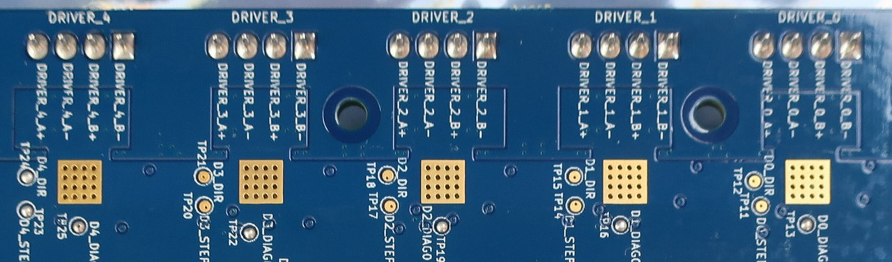
Подключение шаговых двигателей Плата Duet 3 Mini 5+ оснащена 5-ю встроенными драйверами управления шаговыми двигателями.
При подключении шаговых двигателей смотрите схему Duet 3 Mini 5plus Wiring.
Выбор шаговых двигателей (перевод статьи Duet3d)
Соответствие драйвера/разъема и конкретной оси задаётся в меню конфигурации I/O Mapping.
Т.е. не обязательно драйвер №0 должен соответствовать оси X.
Для ВСЕХ ПЛАТ DUET вы должны подключить два провода одной фазы шагового двигателя к двум контактам на одной стороне разъема, а провода другой фазы соединить к двум контактам на другом стороне разъема.
Каждый разъем шагового двигателя на плате имеет четыре контакта.
На Duet 3 Mini 5+ четыре контакта разъема двигателя помечены как «B- B+ A- A+» на задней стороне платы и на схеме подключения.
«A» и «B» обозначают номер катушки (фазы), «-» и «+» обозначают выводы катушки.
Т.е. выводы одной катушки обозначены B- и B+, а другой A- и A+.
Внимание! Некорректное подключение фаз на 4-контактном разъеме может привести к повреждению драйвера.
Поэтому необходимо определить пары проводов принадлежащие одной фазе. Неважно, какую фазу вы подключаете к какой паре контактов или в каком направлении вы подключаете каждую фазу. Смена местами двух фаз или смена местами пары проводов в фазе просто заставит двигатель вращаться в другую сторону, что можно исправить в файлах конфигурации.
Будьте особенно осторожны при использовании шаговых двигателей с разъёмами!
Двигатели Nema 17 с разъёмами обычно имеют 6-контактный разъем JST, но разные производители используют разные контакты на этом разъеме. Всегда проверяйте фазы шагового двигателя при использовании двигателей с разъёмами.
Настоятельно рекомендуется заземлить корпус шаговых двигателей, особенно в принтерах с ременным приводом. В противном случае движение ремней вызовет накопление статического заряда, который в конечном итоге попадёт на обмотки. Движение нити в экструдерах также может вызвать накопление статического заряда на приводном двигателе экструдера. Если моторы закреплены к металлическому корпусу принтера, достаточно заземления корпуса.
Определение фаз шагового двигателя Далее приведены два способа определения фаз шагового двигателя:
- Используйте мультиметр.
Между двумя выводами одной фазы должно быть сопротивление в несколько Ом. Между двумя выводами разных фаз сопротивление должно быть бесконечным. - Соедините выводы обмотки между собой.
Когда провода двигателя ни к чему не подключены, вращайте шпиндель пальцами. Соедините два вывода между собой и снова поверните вал двигателя. Если вращать вал стало сложнее, то два вывода принадлежат одной фазе. В противном случае попробуйте еще раз с другой парой выводов.
Источник
gloomyandy / reprapfirmware
Goto Github
PK
View Code? Open in Web Editor
NEW
This project forked from sdavi/reprapfirmware
55.0
61.0
110.77 MB
OO C++ RepRap Firmware
License: GNU General Public License v3.0
HTML 0.02%
Batchfile 0.01%
C++ 36.07%
C 63.65%
Makefile 0.05%
Perl 0.02%
Go 0.03%
CMake 0.09%
Python 0.07%
Assembly 0.01%
GAP 0.01%
G-code 0.01%
reprapfirmware’s Introduction
LPC/STM32 Port of RepRapFirmware v3
This is aport of RepRapFirmware for LPC1768/LPC1769 and STM32 based boards.
What is it?
It is a port of the RepRapFirmware version 3 (RRF3) used on the Duet family of controllers.
The firmware can be used to control 3D printers, CNC machines, laser cutters and more.
There are a couple of features which sets it aside from Marlin, Smoothieware etc
- All settings for the firmware are configurable dynamically. No recompiling required
- Although it supports USB control through software such as Pronterface or Octoprint, the Duet Web Control (DWC) is the best way to control and configure the software
- Native network control through Wifi, Ethernet or an SBC
The boards which are currently supported are detailed in the wiki here
Main Differences to the Duet RRF
The main differences for the LPC Port are detailed within the wiki here
The main differences for the STM32 Port are detailed within the wiki here
Getting Started
Information to support using this firmware can be found on the wiki
The wiki also details different methods of connecting for different boards.
Support
For LPC/STM specific questions (and general questions too), please get in touch over at the RepRap Forum
There is also a Discord Channel where LPC/STM support can also be found.
For generic RepRapFirmware questions, please use the Duet Forum
The LPC/STM port is experimental and is likely to contain bugs — Use at your own risk
Licence
The source files in this project are licensed under GPLv3, see http://www.gnu.org/licenses/gpl-3.0.en.html.
Documentation
All documentation has been moved to the RepRapFirmware GitHub Wiki.
reprapfirmware’s People
reprapfirmware’s Issues
SKR V1.4 Turbo+ESP8266 «Failed to initialise WiFi module, code -7»
Having an issue, with activating ESP8266 wifi and Skr V1.4 Turbo
Spend hours trying to troubleshoot the error, rechecked all the connections, resistor values and config files, but always getting the error.
`Printer is now online.
M552 S0
SENDING:M552 S0
WiFi module started
ok T0:-273.1 /0.0 B:-273.1 /0.0
Error: Failed to initialise WiFi module, code -7`
M587 S»your SSID» P»your password» results in»
Error: M587: Failed to add SSID to remembered list
When I send «M552 S0», ESP8266 blue led flashes briefly.
Tried re-flashin the module multiple times, with the latest «DuetWifiServer.bin». Always success.
Skr V1.4 Turbo is flashed with the latest firmware-wifi.bin (renamed to firmware.bin)
board.txt
How to connect correctly Ormerod IR sensor in analog mode?
i connect in digital mode, but want to connect right in analog (same as to Duet board). If i connect the sensor in analog mode, sensor dosn`t work…
I change M558 P1 (from P1 to P10), but nothing change (sensor not working or pin does not support a connection )
In digital mode work with M574 Z1 S2 & M558 P1 C»e1temp» H5 F200 T9000 I0 R0.5
a way to re-define in boards.txt SBC pins
can be added options to redefine APIN_SBC_SPI_MOSI ,APIN_SBC_SPI_MISO and so ?
to be able to use other pins than the ones on exp2
SKR 1.3 reset when starting a job
Hi
Randomly, when I have completed a job and start a new one the SKR reboots. Sometimes this happens twice in a row then it will print just fine. This happens on 3 of my machines with the SKR 1.3 in SBC configuration with a Pi 3 A+
All have stable meanwell power supplies and Pi and aux power is connected via bespoke pcb.
Any advice would be appreciated.
My config.g of one of the smaller machines
`G90 ; send absolute coordinates…
M83 ; …but relative extruder moves
M550 P»Helios» ; set printer name
M667 S1 ; select CoreXY mode
; Drives
M569 P0 S1 T0.1:0.1:0.02:0.02 D2 ; physical drive 0 goes forwards using default driver timings
M569 P1 S1 T0.1:0.1:0.02:0.02 D2 ; physical drive 1 goes forwards using default driver timings
M569 P2 S0 T0.1:0.1:0.02:0.02 D2 ; physical drive 2 goes forwards using default driver timings
M569 P3 S0 T0.1:0.1:0.02:0.02 D2 ; physical drive 3 goes forwards using default driver timings
M584 X0 Y1 Z2 E3 ; set drive mapping
M350 X16 Y16 Z16 E16 I1 ; configure microstepping with interpolation
M92 X80 Y80 Z200 E430 ; set steps per mm
M566 X900.00 Y900.00 Z60.00 E2000.00 P1 ; set maximum instantaneous speed changes (mm/min)
M203 X30000.00 Y30000.00 Z2000.00 E3000.00 ; set maximum speeds (mm/min)
M201 X5000.00 Y5000.00 Z120.00 E1000.00 ; set accelerations (mm/s^2)
M204 P1000.00 T5000.00
M906 X1000 Y1000 Z1200 E900 I70 ; set motor currents (mA) and motor idle factor in per cent
;M84 S20 ; Set idle timeout
M593 F40.5 ;M593: Configure Dynamic Acceleration Adjustment
; Axis Limits
M208 X-17 Y-29 Z0 S1 ; Set axis max travel
M208 X330 Y330 Z300 S0 ; set axis maxima
; Endstops
M574 X1 S1 P»xstop» ; configure active-high endstop for low end on X via pin xstop
M574 Y1 S1 P»ystop» ; configure active-high endstop for low end on Y via pin ystop
M574 Z1 S2 ; configure Z-probe endstop for low end on Z
; Z-Probe
M558 P9 H2 F680 T8000 X0 Y0 Z1 C»^zstop» A10 S0.03 ; disable Z probe but set dive height, probe speed and travel speed
M950 S0 C»servo0″ ; Setup servo 0 as servo port on SKR
;M558 P5 C»zstop» H2 F480 T9000 R1 A10 S0.03 ; set Z probe type to switch and the dive height + speeds
G31 P300 X-23.5 Y0 Z1.25 ; set Z probe trigger value, offset and trigger height
M557 X40:290 Y40:290 P5 ; define mesh grid
; Heaters
M308 S0 P»bedtemp» Y»thermistor» T100000 B3950 ; configure sensor 0 as thermistor on pin bedtemp
M950 H0 C»bed» T0 ; create bed heater output on bed and map it to sensor 0
M307 H0 B0 S1.00 ; disable bang-bang mode for the bed heater and set PWM limit
M140 H0 ; map heated bed to heater 0
M143 H0 S130 ; set temperature limit for heater 0 to 130C
M308 S1 P»th1″ Y»thermistor» T95002.69 B4322.60 ; configure sensor 1 as thermistor on pin e0temp
;M308 S1 P»P1.21″ Y»thermocouple-max31855″
M950 H1 C»he0″ T1 ; create nozzle heater output on e0heat and map it to sensor 1
M307 H1 B0 S1.00 ; disable bang-bang mode for heater and set PWM limit
; Fans
M950 F0 C»fan0″ Q500 ; create fan 0 on pin fan0 and set its frequency
M106 P0 S0 H-1 ; set fan 0 value. Thermostatic control is turned off
M950 F1 C»e1heat» Q500 ; create fan 1 on pin he1 and set its frequency
M106 P1 H1 T50 ; set fan 1 value. Thermostatic control is turned on at 50 deg C
; Tools
M563 P0 D0 H1 F0 ; define tool 0
G10 P0 X0 Y0 Z0 ; set tool 0 axis offsets
G10 P0 R0 S0 ; set initial tool 0 active and standby temperatures to 0C
; Custom settings are not defined
T0 ;select tool
M501 `
boards.txt
`lpc.board = biquskr_1.3;
//LED blinks to indicate Platform is spinning or other diagnostic
//Comment out or set to NoPin if not wanted.
leds.diagnostic = NoPin;
//Internal SDCard SPI Frequency.
lpc.internalSDCard.spiFrequencyHz = 25000000;
//LCD Pins (only ST9720 SPI currently supported)
//setup the Software SPI Pins for LCD
heat.tempSensePins = {bedtemp, e0temp}; //Max of 3 entries
//Soft SPI Temp sensor to use with MAX31865+PT100
//softwareSPI.pins = {1.18,1.19,1.20}
//heat.spiTempSensorCSPins = {1.21, NoPin }; //Max of 2 entries
//heat.spiTempSensorChannel = 2
//Analogue to Digital prefilter
adc.prefilter.enable = true
sbc.lpcTfrReadyPin = 1.31
//serial.aux.rxTxPins = { NoPin, NoPin }
//TMC Smart Drivers
stepper.enablePins = { 2.1, 2.8, 0.21, 2.12, 0.10 }
stepper.stepPins = { 2.2, 0.19, 0.22, 2.13, 0.1 }
stepper.directionPins = { 2.6, 0.20, 2.11, 0.11, 0.0 }
stepper.digipotFactor = 0.00
stepper.TmcUartPins = { 1.17, 1.15, 1.10, 1.8, 1.1 }
stepper.numSmartDrivers = 4; //Adjust to the correct number of smart drivers
stepper.TmcDiagPins = { NoPin, NoPin, NoPin, NoPin, NoPin }
`
Wifi Interface dont work
- WiFi —
Network state is changingMode
WiFi module is idle
Failed messages: pending 0, notready 0, noresp 2
Failed to get WiFi status
Socket states: 0 0
WiFi module is connected to access point BEAGLE_2.4G, IP address 192.168.2.60
WiFi module is idle
WiFi reported error: �
WiFi module is in an unknown state
Error retrieving WiFi status message: bad reply format version
[ERROR] Error retrieving WiFi status message: bad reply format version
WiFi module is connected to access point BEAGLE_2.4G, IP address 192.168.2.60
WiFi module is idle
WiFi module is connected to access point BEAGLE_2.4G, IP address 192.168.2.60
WiFi module is idle
WiFi module is connected to access point BEAGLE_2.4G, IP address 192.168.2.60
WiFi module is idle
WiFi module is connected to access point BEAGLE_2.4G, IP address 192.168.2.60
WiFi module is idle
Error retrieving WiFi status message: bad reply format version
[ERROR] Error retrieving WiFi status message: bad reply format version
WiFi module is connected to access point BEAGLE_2.4G, IP address 192.168.2.60
WiFi module is idle
Attempted to write invalid text to console, which could be due to an invalid baudrate
WiFi module is idle
WiFi module is connected to access point BEAGLE_2.4G, IP address 192.168.2.60
WiFi module is idle
WiFi module is connected to access point BEAGLE_2.4G, IP address 192.168.2.60
WiFi module is idle
WiFi reported error: �
WiFi module is in an unknown state
Error retrieving WiFi status message: bad reply format version
[ERROR] Error retrieving WiFi status message: bad reply format version
WiFi module is connected to access point BEAGLE_2.4G, IP address 192.168.2.60
WiFi module is idle
Enable PSU_CONTROL
I use a BTT Relay connected to pin 1.24 on my SKR 1.3
In Marlin i have defined:
#define PSU_CONTROL
#define PSU_NAME «Power Supply»
#define PS_ON_PIN P1_24
#define PSU_ACTIVE_HIGH true
Is this possible in RRF?
Thanks for Help!
Touchscreen support
Hi! thank you for your great job, I really love this firmware.
I’m trying to get a BTT touch screen display to work on a SKR 1.4.
Unfortunately for now without success.
It seems that the serial port don’t works as it should (clearly after enabling it with M575 P1 B115200 S1 in config.g).
I also tried with a classic USB / TTL converter but no reply from board.
What am I doing wrong?
Z probe stuck at 1000 with SBC firmware only
I’ve used the wifi firmware without probe problem, but when I switched to the sbc firmware, the z probe value stay at 1000, whatever the probe state (retract / deploy / hit). I didn’t change wires during the switch, except replace the wifi board by the rpi cable.
I tried with another probe pin (e1det) and without connect the pin, that gives the same result.

M119
Endstops - X: at min stop, Y: not stopped, Z: no endstop, Z probe: at min stop
Using the last pre-release LPC_RRFv3.1.1-14.
Configuration:
- SKR 1.4 Turbo
- BL Touch v3.1 original, wired on dedicated servo and probe pins
- RPI3B+ prepared and wired following the wiki page.
config.g
M558 P9 F100 H3 R0.2 T6000 B1 C"^probe"
M950 S0 C"servo0"
G31 P500 X35 Y-33.5 Z3.55
M557 X35:285 Y15:265 S50
board.txt
lpc.board = biquskr_1.4;
sbc.lpcTfrReadyPin = 1.31
adc.prefilter.enable = true
stepper.numSmartDriver = 5
leds.diagnostic = NoPin;
heat.tempSensePins = {bedtemp, e0temp};
I expect the probe working the same way with both firmwares.
No matter what I do, the duet web control page says «Failed to connect to 192.168.168.101 DCS not started»
Ive checked the wires connecting my raspi to my skr 1.3, they are all correct, yet no matter what i do it always says it cant connect. I have the firmware on the skr and on the raspi.
WiFi connector «dummy» ?
Control LED strip on skr 1.4
Hi,
Seems that M150 is not yet implemented for LED strip control.
Any idea about using the native neopixel pin on skr 1.4 with neopixel like LED strip ?
Thank you.
Relevant info missing in wiki: BTT-EXP-MOT v1.0
Hi,
Have experienced that the EXP-MOT-support is first implemented after last stable build.
From my point of view, this is only mentioned in the ToDo-list and the changelogs, but should also be mentioned in the wiki:
https://github.com/gloomyandy/RepRapFirmware/wiki/PCR-Driver-Adaptor
Also, it is written «The defining of the pins is not required on the latest unstable builds.»
This is correct, but from my experience, defining them makes things NOT work. This is recommended writing more explicit for new users.
I couldn’t find and option to make a pull request to the wiki, so I put it here. If there is an option, i can of course write a request, if i’m given the proper instructions 👍
missing firmware for the screen bigtree TFT 7″ for reprap
I have SKR 1.4 turbo and bigtree TFT 7″ and i cant find the right firmware for the screen for reprap
[BUG] Filament runout not working
I have defined a filament runout sensor, the message appears, but the printhead do not move to the position set in pause.g
It looks like pause.g is not called
;config.g
; Filament sensor Extruder 0
M591 P2 D0 C»xstopmax» S1
and my
; pause.g
; called when a print from SD card is paused
;
; generated by RepRapFirmware Configuration Tool v3.1.3-LPC on Mon Aug 03 2020 18:49:08 GMT+0200 (Mitteleuropäische Sommerzeit)
M83 ; relative extruder moves
G1 E-10 F3600 ; retract 10mm of filament
G91 ; relative positioning
G1 Z5 F360 ; lift Z by 5mm
G90 ; absolute positioning
G1 X0 Y0 F6000 ; go to X=0 Y=0
Motor phase disconnected
Hello guys. I and my mate having same problem with this firmware.
Warning: motor phase A may be disconnected reported by driver(s) 1
Warning: motor phase A may be disconnected reported by driver(s) 0
on original DuetWifi on same config there are no errors. Maybe someone has this issuaes and know how to fix?
SKR 1.4 dual-z
It´s possible to configure dual z on skr1.4 with this firmware?
LPC — TMC drivers
I appreciate that this is in its infancy, but will other TMC options become available, 5160 for example?
Thanks in advance.
LPConfigurator
First I would like to say this is awesome work every version gets better. I wish I had the ability to assist with this project.
I think the LPConfigurator is not up to date
Sensorless homing skr 1.4 + tmc2209 not working
Hi i followed this guide step by step:
also checkout out the documentation on sensorless homing, but it never triggers. I have connected the TMC2209 to skr 1.4 board like shown here:

But still no luck when running:
M574 X1 S3 ; configure endstop for stall detection
M915 P0 S-127 H10 R1 ; Set very sensitive stall detect
G1 X200 H1 ; Should stall pretty much immediately
Is there something I am missing here? It’s not a faulty driver since i’ve 3 seperate TMC2209’s
How to change Duet Web Server Port on SBC
Hi,
I’ve installed SBC version on Raspberry Pi 3B+ and I’ve other services on RPi that http port 80 is busy.
May I know how to change Duet Web Server port on Raspberry Pi Duet Web Server config files?
Thank you
Support for SKR E3 Mini v2.0
Just wondering if you are going to support v2.0 of the new SKR E3 Mini board as well?
Bigtreetech SKR v1.4 BLTouch
So i followd your new instruction on BLTouch. But its not trigering. Also when i unplug the probe pins its triggered.
Heres my config
; Configuration file for SKR v1.4 (firmware version 3)
; executed by the firmware on start-up
;
; generated by RepRapFirmware Configuration Tool v3.1.3-LPC on Sat Jul 11 2020 16:57:13 GMT+0200 (Midden-Europese zomertijd)
; General preferences
G90 ; send absolute coordinates…
M83 ; …but relative extruder moves
M550 P»Artillery genius» ; set printer name
; Network
M552 S1
M552 P0.0.0.0 S1 ; enable network and acquire dynamic address via DHCP
M586 P0 S1 ; enable HTTP
M586 P1 S0 ; disable FTP
M586 P2 S0 ; disable Telnet
; Drives
M569 P0 S0 T0.1:0.1:0.02:0.02 ; physical drive 0 goes backwards using TMC220x driver timings
M569 P1 S0 T0.1:0.1:0.02:0.02 ; physical drive 1 goes backwards using TMC220x driver timings
M569 P2 S1 T0.1:0.1:0.02:0.02 ; physical drive 2 goes forwards using TMC220x driver timings
M569 P3 S0 T0.1:0.1:0.02:0.02 ; physical drive 3 goes backwards using TMC220x driver timings
M584 X0 Y1 Z2 E3 ; set drive mapping
M350 X16 Y16 Z16 E16 I1 ; configure microstepping with interpolation
M92 X80.12 Y80.12 Z399.78 E445.00 ; set steps per mm
M566 X900.00 Y900.00 Z12.00 E120.00 ; set maximum instantaneous speed changes (mm/min)
M203 X6000.00 Y6000.00 Z180.00 E1200.00 ; set maximum speeds (mm/min)
M201 X500.00 Y500.00 Z20.00 E250.00 ; set accelerations (mm/s^2)
M906 X800 Y800 Z1200 E800 I30 ; set motor currents (mA) and motor idle factor in per cent
M84 S30 ; Set idle timeout
; Axis Limits
M208 X0 Y0 Z0 S1 ; set axis minima
M208 X225 Y225 Z250 S0 ; set axis maxima
; Endstops
M574 X1 S1 P»!xstop» ; configure active-high endstop for low end on X via pin xstop
M574 Y1 S1 P»!ystop» ; configure active-high endstop for low end on Y via pin ystop
M574 Z1 S2 ; configure probe port for BLtouch output
; Z-Probe
M558 P9 H6 F120 T8000 X0 Y0 Z1 C»^probe» ; disable Z probe but set dive height, probe speed and travel speed ; set Z probe type to bltouch, set dive height, probe speed + travel speed
M950 S0 C»servo0″ ; create servo pin 0 for BLTouch
G31 P500 X-31 Y80 Z3.25 ; set Z probe trigger value, offset and trigger height (smaller number means nozzle further from bed)
M557 X35:275 Y35:300 S40 ; define mesh grid
; Heaters
M308 S0 P»bedtemp» Y»thermistor» T100000 B4092 ; configure sensor 0 as thermistor on pin bedtemp
M950 H0 C»bed» T0 ; create bed heater output on bed and map it to sensor 0
M307 H0 B0 S1.00 ; disable bang-bang mode for the bed heater and set PWM limit
M140 H0 ; map heated bed to heater 0
M143 H0 S120 ; set temperature limit for heater 0 to 120C
M308 S1 P»e0temp» Y»thermistor» T100000 B4092 ; configure sensor 1 as thermistor on pin e0temp
M950 H1 C»e0heat» T1 ; create nozzle heater output on e0heat and map it to sensor 1
M307 H1 B0 S1.00 ; disable bang-bang mode for heater and set PWM limit
; Fans
M950 F0 C»fan0″ Q500 ; create fan 0 on pin fan0 and set its frequency
M106 P0 S0 H-1 ; set fan 0 value. Thermostatic control is turned off
M950 F1 C»he1″ Q500 ; create fan 1 on pin he1 and set its frequency
M106 P1 H1 T50 ; set fan 1 value. Thermostatic control is turned on at 50 deg C
; Tools
M563 P0 D0 H1 F0 ; define tool 0
G10 P0 X0 Y0 Z0 ; set tool 0 axis offsets
G10 P0 R0 S0 ; set initial tool 0 active and standby temperatures to 0C
; Miscellaneous
M575 P1 S2 B57600 ; enable support for PanelDue
M501 ; load saved parameters from non-volatile memory
T0 ; select first tool
SKR PRO Print stop for no reason and marked as finished 100%
i have SKR PRO with SBCC PI 3B+
issues
1-SKR PRO Print stop for no reason and marked as finished 100% its like the PI crash because i cant change anything in the DWC , i cant load any prints or reprint and i have to reboot both the SKR Pro and the PI
2-when i do the auto calibration g32 when its done it says response too long but it give value as if it passes
3-G29 i get a red error saying errors then it says successful my M558 is M558 P8 H2 F1000 T12000 R0.2 S0.03 A5 C»servo0″
my system is
Board: biquskrpro_1.1 (STMSBC)
DSF Version: 3.2.0-beta4
Firmware: RepRapFirmware for STM32F4 based Boards 3.2-beta4.1_1 (2020-12-03)
printer is Anyquibic Predator Delta
my m122
m122
=== Diagnostics ===
RepRapFirmware for STM32F4 based Boards version 3.2-beta4.1_1 running on STM32F4 (SBC mode)
Used output buffers: 1 of 40 (10 max)
=== RTOS ===
Static ram: 26240
Dynamic ram: 77236 of which 76 recycled
Never used RAM 26492, free system stack 135 words
Tasks: Linux(blocked,115) HEAT(blocked,298) MAIN(running,653) IDLE(ready,20)
Owned mutexes: HTTP(MAIN)
=== Platform ===
Last reset 00:01:07 ago, cause: [power on/off]
Last software reset time unknown, reason: User, none spinning, available RAM 28024, slot 2
Software reset code 0x0012 HFSR 0x00000000 CFSR 0x00000000 ICSR 0x00400000 BFAR 0xe000ed38 SP 0xffffffff Task Linu
Error status: 0x00
MCU temperature: min 36.0, current 37.8, max 38.1
Driver 0: position 124255, standstill, SG min/max 0/6, error r/w 0/0, ifcnt 14, cnt r/w 5814/14, timeout 0, failedOp 0xff
Driver 1: position 197892, standstill, SG min/max 0/8, error r/w 0/0, ifcnt 13, cnt r/w 5815/13, timeout 0, failedOp 0xff
Driver 2: position 124201, standstill, SG min/max 0/8, error r/w 0/0, ifcnt 13, cnt r/w 5814/13, timeout 0, failedOp 0xff
Driver 3: position 0, standstill, SG min/max 0/0, error r/w 0/0, ifcnt 11, cnt r/w 5816/11, timeout 0, failedOp 0xff
Driver 4: position 0
Driver 5: position 0
Driver 6: position 0
Driver 7: position 0
Driver 8: position 0
Driver 9: position 0
Driver 10: position 0
Date/time: 2020-12-15 02:13:22
Slowest loop: 95.75ms; fastest: 0.05ms
=== Move ===
FreeDm 100 (min 97), maxWait 29600ms, bed compensation in use: none, comp offset 0.000
=== DDARing ===
Scheduled moves 4, completed moves 4, hiccups 0, stepErrors 0, LaErrors 0, Underruns [0, 0, 0], CDDA state -1
=== Heat ===
Bed heaters = 0, chamberHeaters = -1
Heater 1 is on, I-accum = 0.0
=== GCodes ===
Segments left: 0
Movement lock held by null
HTTP* is doing «M122» in state(s) 0
Telnet is idle in state(s) 0
File is idle in state(s) 0
USB is idle in state(s) 0
Aux is idle in state(s) 0
Trigger* is idle in state(s) 0
Queue is idle in state(s) 0
LCD is idle in state(s) 0
SBC is idle in state(s) 0
Daemon is idle in state(s) 0
Aux2 is idle in state(s) 0
Autopause is idle in state(s) 0
Code queue is empty.
=== Filament sensors ===
Extruder 0 sensor: ok
=== SBC interface ===
State: 4, failed transfers: 0
Last transfer: 3ms ago
RX/TX seq numbers: 2149/2149
SPI underruns 0, overruns 0
Number of disconnects: 0, IAP RAM available 0x07178
Buffer RX/TX: 0/0-0
=== Duet Control Server ===
Duet Control Server v3.2.0-beta4
Code buffer space: 4096
Configured SPI speed: 8000000 Hz
Full transfers per second: 35.61
BIGTREETECH PITFT50
If i hook up my pie to BIGTREETECH PITFT50 screen
is there a chans to have this screen to show like a original reprap screen?
Or is it nott supported?
Best regards Jan Noord/Sweden
Wifi not working with SKR 1.4 Turbo
Hi, I am using the latest firmware release (3.1.1-14) on my SKR 1.4 Turbo with DuetWebControl Version 3.1.1.
I flashed an ESP8266 with the latest release of Duet WiFi Socket Server for LPC1768 version of RRF, and wired it up on a breadboard according to the wiki.
When I connect to the printer through Pronterface and send M552 S0, the LED on my esp flashes once and I get
SENDING:M552 S0
WiFi module started
Error retrieving WiFi status message: bad reply format version
[ERROR] Error retrieving WiFi status message: bad reply format version

Error retrieving WiFi status message: bad reply format version
[ERROR] Error retrieving WiFi status message: bad reply format version
When i then try to send M587 S"SSID" P"password" (with my actual SSID and password), the LED on the esp stays off and I get
SENDING:M587 S"SSID" P"password"
Error: M587: Failed to add SSID to remembered list
[ERROR] Error: M587: Failed to add SSID to remembered list
Then, when I send M552 S1, the LED on the esp flashes once and I get
SENDING:M552 S1
Failed to change WiFi mode (code -10)
After turning the printer off and on again, when I send M552 S0, the LED on the esp flashes once and I get
SENDING:M552 S0
WiFi module started
Error: Failed to initialise WiFi module, code -10
[ERROR] Error: Failed to initialise WiFi module, code -10
Typo in the Sbase Manual
[BUG] SKR 1.3 WIFI trigger filament runout
I use the SKR 1.3 with the WIFI module from tindie
I noticed that when my computer, on which the WebFrontend is open, goes into standby, my filament runout trigger is executed.
;0:/sys/config.g
; Filament sensor Extruder 0
M950 J1 C»xstopmax» ; filament monitor connected to xstopmax
;0:/sys/start.g
M581 P1 S1 T2
BABY STEPS not working
New install , no matter how many times I press the move closer button nothing happens. Took it down 3.0 mm and it never moved
Board: biquskr_1.3 (LPCWiFi)
Firmware: RepRapFirmware for LPC176x based Boards 3.1.1-14 (2020-17-7b14)
Duet WiFi Server Version: 1.23-01L-D
[FAQ] SKR 1.3 MBED=true ?
For the SKR 1.3 set the MBED=true ?
[FR] Shutdown SBC after printjob finish
In combination with a Relay it would be nice if it is possible to shutdown the SBC after print is finish, before power off
Max3155 temperature issue
I am running an SKR 1.3 board with sbc and a max3155 chip for the hotend.
The temperature is very stable if I heat the hotend and manually move the printer axis. Turning on the heatbed does not impact on the readings.
Once I start a print almost every second temperature reading is 2000c. Sometimes the print will fail due to disconnect being registered.
Any advice please?
board.txt
leds.diagnostic = NoPin;
//Internal SDCard SPI Frequency.
lpc.internalSDCard.spiFrequencyHz = 25000000;
heat.tempSensePins = {bedtemp}; //Max of 3 entries
//Soft SPI Temp sensor to use with MAX31865+PT100
softwareSPI.pins = {1.18,1.19,1.20}
heat.spiTempSensorCSPins = {1.21, NoPin }; //Max of 2 entries
heat.spiTempSensorChannel = 2
//Analogue to Digital prefilter
adc.prefilter.enable = true
sbc.lpcTfrReadyPin = 1.31
//TMC Smart Drivers
stepper.numSmartDrivers = 4; //Adjust to the correct number of smart drivers
stepper.TmcDiagPins = { NoPin, NoPin, NoPin, NoPin, NoPin }
config.g
M308 S1 P»P1.21″ Y»thermocouple-max31855″
Max31855
Hi
Is it possible to use a MAX31855 termocouple amplifier with this port of the RRF?
DWC crash
Hello, I’m having ad issue every time I launch a print, the DWC and Wifi ESP module go in crash, it lost the wifi connection but the print starts equally.
The DWC is at latest version, everithing works outside of this.
How can I fix it?
Thank you.
SKR v1.4 Turbo, SBC and Dual Z Motors -> No Compensation
Hi, i use the same Setup on a Duet Wifi with DueX5 and also on a Duet Maestro. All of the Printers are equipped with 2 Motors for Z and therefore i make use of the Leveling of the X-Axis Gantry before levelling the Bed.
Now my 3rd Printer is equipped with SKR v1.4 Turbo, 5 TMC 2209 Drivers and a Pi 4 as the SBC.
Everything seems to be working beneath 4 Facts:
1st: If in the Configuration
M584 X0 Y1 Z2:4 E3                              ; set drive mapping
M350 X16 Y16 Z16 E16 I1                         ; configure microstepping with interpolation
The Axis behaves normally incl. the Z — Axis
In the original Firmware i configure normally:
M584 X0 Y1 Z2:4 E3                              ; set drive mapping
M350 X16 Y16 Z16:16 E16 I1                         ; configure microstepping with interpolation
This leads to an error-Message if i use it in the LPC-Port cause then Driver 4 will run with «0 Steps»…
2nd: Normally i need to configure the Motor-Amps via M906 for both Z-Motors:
Like here:
M906 X900 Y1000 Z850:850 E1000 I30
But if i do this in the LPC-Port, the Z-Drives will only going down, never up. I have got headache from this
M906 X900 Y1000 Z1000 E1000 I30
3rd: My Bed-Leveling do noting. No Chance that the Gantry will be leveled.
I use this for G32:
M561 ; clear any bed transform
G29 S2
; If the printer hasn't been homed, home it
if !move.axes[0].homed || !move.axes[1].homed || !move.axes[2].homed
	G28 ; home

; Probe the bed and do auto calibration
G1 X5 Y155 F6000        ; go to just above the first probe point
while true
	if iterations = 15 ;max 15 Testdurchläufe
		abort "Zu viele Auto-Kalibrierungs Versuche"
	G30 P0 X47 Y155 Z-99999 ; Spindel Z-1
	if result != 0
		continue
	G30 P1 X275 Y155 Z-99999 S2 ; Spindel Z-2
	if result != 0
		continue
	if move.calibration.initial.deviation <= 0.003 ;max abweichung Je nach Z-Probe anpassen!
		break
	else
		echo "wiederhole Kalibrierung da Abweichung zu hoch (" ^ move.calibration.initial.deviation ^ "mm)"
echo "Auto kalibrierung erfolgreich, Abweichung von: ", move.calibration.initial.deviation ^ "mm"
echo "Happy Printing"
;end loop
G29  ; probe the bed and enable compensation
But the outcome is frustrating:
  | M98 P"0:/macros/Level-Z"Error: Some computed corrections exceed configured limit of 0.50mm: 0.208 -0.792 Error: Some computed corrections exceed configured limit of 0.50mm: 0.210 -0.789 Error: Some computed corrections exceed configured limit of 0.50mm: 0.205 -0.789 Error: Some computed corrections exceed configured limit of 0.50mm: 0.207 -0.790 Error: Some computed corrections exceed configured limit of 0.50mm: 0.212 -0.789 Error: Some computed corrections exceed configured limit of 0.50mm: 0.209 -0.790 Error: Some computed corrections exceed configured limit of 0.50mm: 0.208 -0.792 Error: Some computed corrections exceed configured limit of 0.50mm: 0.213 -0.794 Error: Some computed corrections exceed configured limit of 0.50mm: 0.210 -0.795 Error: Some computed corrections exceed configured limit of 0.50mm: 0.209 -0.792 Error: Some computed corrections exceed configured limit of 0.50mm: 0.208 -0.795 Error: Some computed corrections exceed configured limit of 0.50mm: 0.206 -0.791 Error: Some computed corrections exceed configured limit of 0.50mm: 0.209 -0.792 Error: Some computed corrections exceed configured limit of 0.50mm: 0.208 -0.792 Error: Some computed corrections exceed configured limit of 0.50mm: 0.208 -0.792 Zu viele Auto-Kalibrierungs Versuche
-- | --
Even this one will missed completely between the different tries:
echo "wiederhole Kalibrierung da Abweichung zu hoch (" ^ move.calibration.initial.deviation ^ "mm)"
Any Ideas?
Regards
MoS-tekknix
[BUG] calibrationDeviation unknown
I found a example bed.g in the Wiki to calibrate the bed.
If i run a G32 command i get the following output
G32
Leadscrew adjustments made: 0.120 0.119, points used 2, (mean, deviation) before (0.119, 0.000) after (0.000, 0.000)
Error: in file macro line 19 column 6: meta command: unknown value ‘calibrationDeviation’
My bed.g
M561                    ; clear any bed transform
; If the printer hasn't been homed, home it
if !move.axes[0].homed || !move.axes[1].homed || !move.axes[2].homed
  G28
while true
  if iterations = 5
    abort "Too many auto calibration attempts"
  G30 P0 X20 Y117.5 Z-99999 ; probe near a leadscrew, half way along Y axis
  if result != 0
    continue
  G30 P1 X215 Y117.5 Z-99999 S2 ; probe near a leadscrew and calibrate 2 motors
  if result != 0
    continue
  if move.calibrationDeviation.deviation <= 0.02
    break
  echo "Repeating calibration because deviation is too high (" ^ move.calibrationDeviation.deviation ^ "mm)"
echo "Auto calibration successful, deviation", move.calibrationDeviation.deviation ^ "mm"
G29  ; probe the bed and enable compensation
SKR 1.3 How do you configure BLTouch in LPCConfigurator?
SKR 1.3 How do you configure BLTouch in LPCConfigurator?
Z Probe pin assignment Input pin selection is there z stop
What are the correct selections for the Modulation Pin and PWM Pin?
esp on esp header vs esp on aux headers
Is there a reason for using an esp8266 via the AUX connectors instead of the esp header already on the skr 1.4 turbo?
G1 + H1 moves only one Z motor
Hi,
I’ve set up my Anycubic i3 with Dual Z and Dual endstops, configured by the book
config.g sections:
; Drives
M569 P0 S1 D3 V40                                             ; X physical drive 0 goes forwards using default driver timings
M569 P1 S0 D3 V40                                            ; Y physical drive 1 goes backwards using default driver timings
M569 P2 S0                                             ; Z1 physical drive 2 goes backwards using default driver timings
M569 P3 S1                                             ; E physical drive 3 goes forwards using default driver timings
M569 P4 S0                                             ; Z2 physical drive 4 goes backwards using default driver timings
M584 X0 Y1 Z2:4 E3                                       ; set drive mapping

M574 Z1 S1 P"!zstop+!pwrdet" 							   ; configure active-low endstops for low end on Z via pins zstop and e1stop
However what I try, while homing Z only one motor is driven while the other one is energized and locked.
In essence I switch to relative position in homez.g and
G1 H1 Z-210 F1800 ; move Z down until the endstop is triggered
If I just move the axis, everything is nice and dandy.
I don’t understand it. Endstops are reported fine and they are assigned to the correct motors.
Bords is a SKR 1.4 running 3.1.1-14
problems with RRF COnfig tool for LPC an BLTouch
Sorry for bothring but is there any know issue with the SKR1.4 and a configured BL-Touch connection on the I/O mapping page of the RRF Config Tool (LPC-Port)?
When i configure any Pins for the BL-Touch there i get an error on the last Page saying that there are errors on the I/O-mapping page. When i leave the BLtouch unconnected anything is fine i can get the config tool to spit out the disired files.
Best regards
René
esp32 support
can you add esp32 support like esp8266 to the project?
No web interface after clean install on SBC
Hi
I am using an SKR 1.3 via SBC connection to a RPI 3A+
It was working fine and I was doing an update.
I ran the update as per the wiki:
wget https://raw.githubusercontent.com/P-C-R/LPC-DSF-Install_Script/master/LPC_DSF_update.sh
sudo chmod 755 LPC_DSF_update.sh
./LPC_DSF_update.sh
after the update to 3.2.0-beta+1 The browser just displays connection refused.
I then re-flashed the sd card with duetpi and tried every one of the stable/unstable wiki instructions with no luck.
Am I missing something here?
[FR] Please provide PlatformIO(Windows/Linux).
It would be very nice if there was a PlatformIO project witch fits to the RRF_LPC
Or even update BuildInstructions.md
how to use Aux-1 Pin
Hi
i use on Marlin P0.03.A6 its a pin from AUX-1 connector i use this for my e3d PT1000 board how can i setup this on reprap ?
[BUG] 2 Independend Z motors (G34)
Sometimes i get this error message:
G30 P0 X20 Y117.5 Z-9999 ; probe near a leadscrew, half way along Y axis
G30 P1 X215 Y117.5 Z-9999 S2 ; probe near a leadscrew and calibrate 2 motors
Error: Some computed corrections exceed configured limit of 1.00mm: -0.737 -1.543
Simulation Times


I’m running the SKR 1.4 Turbo in SBC mode with a raspberry pi 3b+. Running the simulation mode takes 2-3 times longer than the duet wifi im using with the same gcode. The results reported in the console are off and the gcode file isn’t updated with the simulation time and is not displayed in the web interface.
That’s all I’ve noticed so far and have been printing great! Thanks for this cool project!
Steven Smith
Dual Z axis creating an U drive separately which is so not homing
Hi. I have an SKR 1.4 configured with the great Reprap firmware.
Similarly to my Duet wifi I configured a dual Z axis to have independent Z axis compensation with a BLtouch.
I have assigned it the following way: M584 X0 Y1 Z2:4 U4 E3
My problem is that it is showing up in the Duet web control as a separate U drive and so due to the reason it is not homing it always drops an error that it is not homed and a G29 mesh bed leveling cannot be initialised.
Am I doing something wrong?
Thank you for your support in advance.
Wrong link in the main readme
To support the number of different boards, a /sys/board.txt config file on the SDCard is used to configure the hardware pin assignments. Some example board config files can be found here
The example board config files are redirected to the «old» repo
Best
TODO list
So this is my current list of the things I’m planning on working on (in a very rough priority order)…
- Create single code base for STM/LPC versions and associated build system.
- Track DC42 3.4 beta and beyond.
- Add support for various expansion boards (GTR M5 and BTT expansion board)
3a. Review/Change limits of various items in particular number of Fans
3b. Find a better way to handle a variable number of drivers in the source to allow easier builds with different memory footprints
3c Sort out MaxProbePoints and MaxCalibration points on LPC version (need to be the same to avoid firmware reset) - Add option to control initial state of PS_ON(complete V3.2-beta3.2).
- Investigate why some/all SanDisk SD cards do not seem to work (complete V3.2-beta2
- Enable support for NeoPixels
- Add 5160 support.
- SDIO support for SD cards.
- Improved pin configuration (avoid need to list all pins in the various board.h files).
- Use CRC32 hardware.
- Update TMC22xx driver to match Duet3D version
- Reduce LPC malloc overhead.
- Provide defaults for WiFi/Linux interface and other settings. Identify board via signature.
13a. Identify board via signature. - Shift Core to new Duet3D model.
- Investigate firmware reset when issuing M552 S1 followed by M997 S1 when no firmware is present in the ESP8266 module.
- Investigate why size reporting of SDIO drives is broken.
- Investigate support for LCD displays (12864 based) for the STM32 port (not enough RAM for LPC).
- Investigate possible problem with UART connections which gives «Bad response» messages when using a PanelDue.
- Fix STM default DiagPin.
- Allow use of Mixed case names in board definitions (force match to ignore case).
- Investigate WiFi performance
- Investigate adding support for object tracking.
- Add support for Bigtreeetech SKR V2.0 (driver rotation detection and power on sequence).
- Expand number of extruders per tool
- Investigate adding support for object tracking to LPC build
- Add support for RGBW NeoPixels
- Test accelerometer support
- Investigate integrating «power detect pins» with the 12/24V power monitoring
- Allow selection of SPI channel for WiFi/SBC interface
- Allow use of alternate pins for hardware PWM
- Allow reading of any TMC register
- Allow use of SPI3 for SD card access — investigate possible DMA access issues
- Check setting of LPC peripheral clock. Consider increasing LPC PWM resolution
- LPC: Consider allowing hardware PWM outputs for other than servos.
- STM: Investigate SDIO errors when daemon.g is running
- STM: Investigate loss of USB in later versions on SKR Pro (unable to reproduce)
- STM: Investigate why TMC5160 in slot 2 of a CDYv2 board gets hot with 5 or more 5160s installed (unable to reproduce)
- STM: Increase number of supported probes
- STM: Improve TMC5160 detection
- Investigate enabling I2C support
- Investigate increasing number of axis
- Investigate setting a fixed IP address for esp32 clients and restore functionality for esp8266 version
- Clamp Vin reading when near zero to stop DWC flicker
- H7 Enable 16bit ADC samples (currently 12 bit with oversampling to 14)
- H7 Use processor d-ram for stacks etc.
- H7 Consider using FIFOs for UARTS
- H7 Investigate SD Card SPI mode high speed switching
- H7 Test SBC Mode
- H7 Build IAP for SBC mode
- Allow use of shared timers per pin (find best match)
- H7 Update hardware usage for H7
- H7 Allow DMA with SPI1, SPI5, SPI6
- Allow use of embeded config
- Allow forcing pins to 0V/3.3V output on boot
- Investigate BTT SKR 3 EZ operation with TMC220x stepsticks
- Investigate Why a board in CAN expansion mode does not get restarted when main board is reset.
- Investigate errors when setting access point parameters (esp32)
- Fix MAC address not be returned in status message
- Investigate using 3 timer/dma operation for neopixels(see https://sites.google.com/site/hubmartin/arm/improved-stm32-ws2812b-library and https://github.com/hubmartin/WS2812B_STM32F4/blob/master/Src/ws2812b/ws2812b.c)
Items 1 and 2 are my main focus at the moment. 3.3 is currently available and 3.4 in test.
I tend to work on things that interest me and that are easy for me to set up (so if I don’t have the hardware and it is not interesting/cheap I’m unlikely to work on it). I am also in the middle of setting up a new printer and have plenty of of other things to do!
Please do not post questions or requests for help or bug reports on this issue. Please use the discord server to ask questions or report possible problems. Thanks!
Minor bug in wiki (wrong link)
On the page for connecting a SBC to the GTR board (https://github.com/gloomyandy/RepRapFirmware/wiki/SKR-GTR-SBC), the link for the board pinout directs to the Pro board pin diagram and not the GTR board pin diagram. The pinouts are almost identical except for PF12 / PB10. On the linked diagram, PB10 is in the stallguard header, on the GTR diagram it’s in EXP2
SKR 1.3 Bed Heater Constantly Faulting
Hi,
I’m running 3.1.1-14 on an SKR 1.3 in SBC mode and am having issues the bed heater faulting out every time I try to heat it.
I’ve ran autotune starting from room temp numerous times, and I’ve even tried manually increasing the dead time but I’m still getting ‘heater fault, temperature rising more slowly than the expected 1.6deg/s’ on the bed heater.
Given that it heats up fine when auto-tuning but faults under normal operation I wanted to raise the issue in case it was a firmware problem?
I’ve manually checked the resistance of the bed and all looks within spec.