Оптовые цены на запчасти и инструмент для ВСЕХ на TexnoMag.ru + доставка по РФ от 99 руб.
Всем доброго времени суток. Прошу помощи по подключению и прошивке модуля EVO II с мк renesas. Подключал модуль по см.рис.1 Пробовал разные программаторы, CH340, CH341 и разные их модели. Схему подключения использовал такую см.рис.2 Подключать ли rst через кнопку и когда ее нажимать? nmi и rst на массу БП или CH340? Софт использую Flash development toolkit. После создания нового проекта нажимаю device — connect to device. Выдает Error No 15024: Boot failed
Полный лог:
FDT API initialised: version 4, 09, 02, 000
FCF Settings Applied: H8/3664F, (C:Program FilesRenesasFDT4.09kernelsProtB3664Renesas1_1_00)
Clock Frequency (External) = 9.8304MHz, Clock Mode = 0, CKM = 1, and CKP = N/A
Connecting to device ‘H8/3664F’ on ‘COM1’
Configuration:
‘BOOT Mode’ connection — using emulated interface
Opening port ‘COM1’ …
Loading Comms DLL
Loaded Comms DLL
Initiating BOOT SCI sequence
Attempting 9600
Attempting 4800
Attempting 2400
Attempting 1200
Error No 15024: Boot failed


Ответы 12
Не помогает, менял — Mobius 10 мая
Да, rx и tx с даташита, наоборот тоже подключал, не пашет — Mobius 10 мая
Спасибо, попробую — Mobius 10 мая
Впаял, все по прежнему как на логах в посте.. — Mobius 10 мая
В диспетчере ch340 определился как com6, в fdt подключаю к нему, глухо — Mobius 10 мая
GND и +5В на программаторе есть, это правда, но для того, чтобы прошить, нужен внешний источник питания. — Chtmist 13 мая
а ошибка это означает -нету синхронизации между между модулем и компом.изучи по программатору инфу — genca 9 мая
Спасибо. На какой раздел даташита смотреть что бы определить частоту? Или откуда ее вообще брать? — Mobius 10 мая
Вы используете готовый проект под EVO2(SWxxx на проц H8/3664F с резонатором 4,91)… эте частоту и ставят в настройке FDT, а даташит дает допустимые параметры. — user659 11 мая
Спасибо, понял — Mobius 11 мая
Хоть убейте, три камня, в логах
Received immediate response from device: 0x55
Error No 15024: Boot failed
или
Received immediate response from device: 0x00
Error No 15024: Boot failed
или
Received immediate response from device: 0xFE
Error No 15024: Boot failed
И постоянно так.
Разок выдал
Received immediate response from device: 0xFF
Error No 16183: 0xFF received — Boot Error or Device failed to erase
Error No 15024: Boot failed — Mobius 11 мая
Я так понял программе не нравится ответ?
Received immediate response from device: 0x00 — Mobius 11 мая
вы видели мое описание прошивки? — ankorservis 11 мая
Где можно ознакомится с процессом котором говорите. — rembyt19 13 мая
я не знаю можно ли давать тут ссылки на сторонние ресурсы, если интересно то скиньте куда бросить ссылку
— ankorservis 13 мая
Моя почта rik.rider.rus@gmail.com
Заранее спасибо за советы и помощь. — Mobius 14 мая
Что делать если, как я понял на третьем этапе болты? МК новые — Mobius 11 мая
Полный последний лог
Clock Frequency (External) = 4.9100MHz, Clock Mode = 0, CKM = 1, and CKP = N/A
Connecting to device ‘H8/3664F’ on ‘COM7’
Configuration:
‘BOOT Mode’ connection — using emulated interface
Opening port ‘COM7’ …
Loading Comms DLL
Loaded Comms DLL
Initiating BOOT SCI sequence
Attempting 9600
Attempting 4800
Attempting 2400
Attempting 1200
Received immediate response from device: 0x00
Error No 15024: Boot failed — Mobius 11 мая
Я так понял программе не нравится ответ?
Received immediate response from device: 0x00 — Mobius 11 мая
Ошибка загрузки ..
Ингда помагает удаление проги и установка заново , купите СН340 , 100% правильно подключить TX RX
В проге выставить всё по картинках , проц исправный новый конечно..
И самое основное — Окрыавете окно Device, потом делаете ресет проца , и наконец кликаете на Connect to Device
ЕСЛИ ВСЁ ПРАВИЛЬНО СДЕЛАЛИ внизу пробегит синяя плоска и лог что всё ОК ..
Третий этам только теперь — открываете прошивку и пишите
или это не ваше .. — user5258 11 мая
вот такой USB TO TTL — user5258 11 мая
Спасибо, все в понедельник посмотрю попробую. По ch340, есть в трех вариантах. Думаю один из них должен быть рабочий. — Mobius 11 мая
Сегодня были изменения в логах с другой платой.
Clock Frequency (External) = N/A, Clock Mode = N/A, CKM = N/A, and CKP = N/A
Connecting to device ‘R5F21254’ on ‘COM10’
Configuration:
‘BOOT Mode’ connection — using emulated interface
Opening port ‘COM10’ …
Loading Comms DLL
Loaded Comms DLL
Initiating BOOT SCI sequence
Attempting 9600
Changing baud rate to 115200 bps
Но я и так выбрал 115200
Потом следущее
Attempting 9600
Error No 15064: Failed to write the data byte(s)
Error No 15064: Failed to write the data byte(s)
Error No 15064: Failed to write the data byte(s)
Changing baud rate to 115200 bps
И в конце
Initiating BOOT SCI sequence
Attempting 9600
Attempting 4800
Changing baud rate to 115200 bps
Error No 16148: Kernel Error Response: 0x0 0x0 Baud Rate change failed — check clock and baud rate compatibility
Error No 15016: Changing baud rate to 115200 bps
В итоге так и ничего.. — Mobius 16 мая
Ну, потом камень просто умер.. — Mobius 16 мая
По РиС 10/2012, все как там, только использую ch340a/341g.
Минус БП и GND CH341 соединены вместе. Частота 4,910, перемычка снята. — Mobius 14 мая
Ваш ответ +1
Содержание
- Renesas Error 15024
- Error No 15024 : Boot failed (on R8C/3GC device) — Forum .
- Flash Development Toolkit (Programming GUI) Renesas
- Renesas USB 3.0 extensible host controller problem on .
- Renesas Electronics Corporation
- Fatal Errors CS+ V4.01.00 — Renesas Electronics
- FAQ 104590 : フラッシュ開発ツールг‚гѓѓгѓ€гЃ§ Boot failed г‚Ёгѓ©гѓј …
- 106: R8C — Forum — Renesas Rulz — Japan
- 32bit Denso SH7052 based ECUs with AUD — ECU hacking
- Fix: Renesas USB Device Error Code 10 — Appuals.com
- new problem, this tme with renesas 😀 — ECU hacking
- Renesas Error 15024 Fixes & Solutions
- Прошу помощи по подключению и прошивке модуля EVO II с мк renesas.
- Прошу помощи по подключению и прошивке модуля EVO II с мк renesas.
- Прошу помощи по подключению и прошивке модуля EVO II с мк renesas.
- Error no 15024 boot failed renesas
Renesas Error 15024

We have collected for you the most relevant information on Renesas Error 15024, as well as possible solutions to this problem. Take a look at the links provided and find the solution that works. Other people have encountered Renesas Error 15024 before you, so use the ready-made solutions.
Error No 15024 : Boot failed (on R8C/3GC device) — Forum .
- https://renesasrulz.com/the_vault/f/archive-forum/7545/error-no-15024-boot-failed-on-r8c-3gc-device
- Dec 14, 2016 · Error No 15024 : Boot failed (on R8C/3GC device)
Flash Development Toolkit (Programming GUI) Renesas
- https://www.renesas.com/us/en/software-tool/flash-development-toolkit-programming-gui
- Renesas Flash Development Toolkit is the dedicated flash programming software for Renesas flash microcomputers, which offers sophisticated and easy-to-use Graphical User Interface. Moreover, when it is used with High-performance Embedded Workshop, it allows the users who involved in development of the embedded application software adopting .
Renesas USB 3.0 extensible host controller problem on .
- https://answers.microsoft.com/en-us/windows/forum/windows_10-hardware-winpc/renesas-usb-30-extensible-host-controller-problem/dcbfe331-7ac3-4ae9-b870-2e7bb88d4243
- Apr 30, 2016 · Hello, Everytime I put my desktop computer in sleep mode (S3 state), the usb 3 ports are not working anymore. In device manager I discovered an exclamation mark at the «Renesas …
Renesas Electronics Corporation
- https://www.renesas.com/
- TOKYO, Japan ― Renesas Electronics Corporation (TSE:6723), a premier supplier of advanced semiconductor solutions, today announced the expansion of its RZ/G2 general-purpose 64-bit microproc. continue reading. Renesas Collaborates with Microsoft to Accelerate Connected Vehicle Development.
Fatal Errors CS+ V4.01.00 — Renesas Electronics
- http://tool-support.renesas.com/autoupdate/support/onlinehelp/csp/V4.01.00/CS+.chm/Message.chm/Output/er_E_msglist-nav-3.html
- Renesas Software and Tools. CubeSuite+ (IDE) for Renesas MCUs. Powerful support for all aspects of embedded application development.
FAQ 104590 : フラッシュ開発ツールг‚гѓѓгѓ€гЃ§ Boot failed г‚Ёгѓ©гѓј …
- https://ja.na4.teamsupport.com/knowledgeBase/17797425
- Q : иіЄе•Џ [フラッシュ開発ツールг‚гѓѓгѓ€ V.2, V.3, V.4 ] д»Ґдё‹гЃ®г‚€гЃ†гЃЄг‚Ёгѓ©гѓјгЃЊе‡єеЉ›гЃ•г‚ЊгЃѕгЃ™гЂ‚жЋЁжё¬гЃ•г‚Њг‚‹еЋџе› гЃЊгЃ‚г‚ЉгЃѕгЃ™гЃ‹пјџ гѓ»ERROR : Boot failed гѓ»No 15024 ERROR : Boot failed A : е›ћз” гЃ“г‚ЊгЃЇгЂЃгѓ•гѓ©гѓѓг‚·гѓҐй–‹з™єгѓ„гѓјгѓ«г‚гѓѓгѓ€гЃ®TimeOutг‚Ёгѓ©гѓјгЃ§гЃ™гЂ‚
106: R8C — Forum — Renesas Rulz — Japan
- https://japan.renesasrulz.com/cafe_rene/f/forum14/2501/r5f21336cuart-mcu
- C:Program Files (x86)RenesasHewToolsRenesasDebugCompPlatformPDTargetKD30McuFilesR8C-Tiny Series. дёгЃ«и¦‹еЅ“гЃџг‚ЉгЃѕгЃ›г‚“гЃ§гЃ—гЃџпјЋ HEWやコンパイラ,デバッガなどのソフトウェアインストールを失敗しているのか,アップデートの有無や配布дёжўгЃЄгЃ©гЃ®гЃЊгЃ‚г‚ЊгЃ°
32bit Denso SH7052 based ECUs with AUD — ECU hacking
- https://ecuhacking.activeboard.com/f401478/32bit-denso-sh7052-based-ecus-with-aud/
- Registered Members: 3,675 Topics: 2,647 Total Posts: 23,153 There are currently 2 member(s) and 4 guest(s) online: yosharilla, Mark40 303 user(s) visited this forum in the past 24 hours The most users ever online at once was 18 member(s) and 163 guest(s) at 12:14pm Sep 07, 2010
Fix: Renesas USB Device Error Code 10 — Appuals.com
- https://appuals.com/fix-renesas-usb-device-error-code-10/
- May 09, 2019 · The code10 error is generated when Device Manager can’t start the hardware device, caused due outdated or corrupted drivers. You will therefore be unable to plug your USB devices into your Renesas port and have them work. Corrupt drivers might lead to this issue. Unreadable instruction will stop the device from starting or working properly.
new problem, this tme with renesas 😀 — ECU hacking
- https://ecuhacking.activeboard.com/t49447185/new-problem-this-tme-with-renesas-d/
- Jun 04, 2012 · new problem, this tme with renesas 😀 Permalink or at least i think thats where the problem lies lol, another day off work means another day tinkering with the bike.
Renesas Error 15024 Fixes & Solutions
We are confident that the above descriptions of Renesas Error 15024 and how to fix it will be useful to you. If you have another solution to Renesas Error 15024 or some notes on the existing ways to solve it, then please drop us an email.
Источник
Прошу помощи по подключению и прошивке модуля EVO II с мк renesas.
Ответы 12
И что ваш СН341 видит FDT ?
Пользуюсь СН340 а ресет делаю — вытягиваю из ПК его и подключаю снова через 20 секунд .
RX TX лучше проследить по даташиту от самого проца ножек до СН340 и подключить наоборот
Проц то флешовый пишите ?
Схема не правильная: общий (gnd) и +5в на программаторе есть. Rx и tx местами поменять.
А программатор точно на COM1?
Ошибка загрузки ..
Ингда помагает удаление проги и установка заново , купите СН340 , 100% правильно подключить TX RX
В проге выставить всё по картинках , проц исправный новый конечно..
И самое основное — Окрыавете окно Device, потом делаете ресет проца , и наконец кликаете на Connect to Device
ЕСЛИ ВСЁ ПРАВИЛЬНО СДЕЛАЛИ внизу пробегит синяя плоска и лог что всё ОК ..
Третий этам только теперь — открываете прошивку и пишите
или это не ваше .. — user5258 11 мая
Сегодня были изменения в логах с другой платой.
Clock Frequency (External) = N/A, Clock Mode = N/A, CKM = N/A, and CKP = N/A
Connecting to device ‘R5F21254’ on ‘COM10’
Configuration:
‘BOOT Mode’ connection — using emulated interface
Opening port ‘COM10’ .
Loading Comms DLL
Loaded Comms DLL
Initiating BOOT SCI sequence
Attempting 9600
Changing baud rate to 115200 bps
Но я и так выбрал 115200
Потом следущее
Attempting 9600
Error No 15064: Failed to write the data byte(s)
Error No 15064: Failed to write the data byte(s)
Error No 15064: Failed to write the data byte(s)
Changing baud rate to 115200 bps
И в конце
Initiating BOOT SCI sequence
Attempting 9600
Attempting 4800
Changing baud rate to 115200 bps
Error No 16148: Kernel Error Response: 0x0 0x0 Baud Rate change failed — check clock and baud rate compatibility
Error No 15016: Changing baud rate to 115200 bps
В итоге так и ничего.. — Mobius 16 мая
Источник
Error no 15024 boot failed renesas


Welcome to the NASIOC.com Subaru forum.
You are currently viewing our forum as a guest, which gives you limited access to view most discussions and access our other features. By joining our community, free of charge, you will have access to post topics, communicate privately with other members (PM), respond to polls, upload content and access many other special features. Registration is free, fast and simple, so please join our community today!
If you have any problems with the registration process or your account login, please contact us.
* As an Amazon Associate I earn from qualifying purchases.
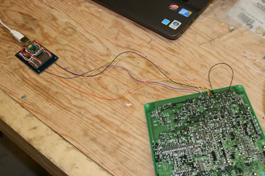
A laptop crash half way through a reflash of my buddies 04 sti rendered the ecu useless. This event drove me to figure out how to recover a bricked ecu.
The forums can be confusing to read and understand and pictures of the rig built/hooked up are scarce. On top of that, tactrix doesn’t offer the ecu recovery service anymore so I had to get right into it.
First of all, you need to be able to soldier or have a friend who can and is willing to help you out to build this thing.
The parts you will need..
Buy this.. DLP-USB232M from mouser.com 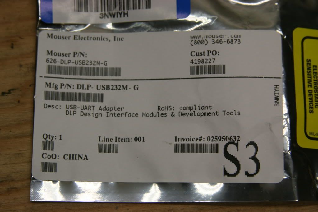
Click Here
The DLP has most of the circut built for you already so you dont need all kinds of parts, only a few.
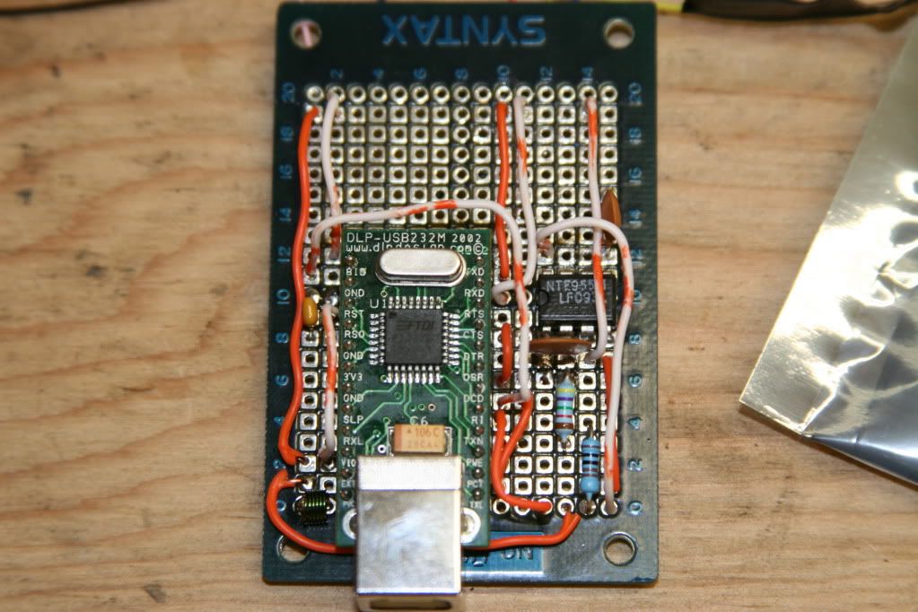
Here is the pdf of the thing you need to build
Here is the DLP schematic (last page). Compare these two and you see that you only need a L1 Ferrite.. AKA a coil of wire for noise removal and you need a .01uf capacitor (reads 103 on it). They connect to EHR-5 pin 1.
VCC is usb voltage.. The down arrow in the shbootmode pdf is ground. The DLP needs to be self powered so you must make a connection on the pins to make it do that. Page 6 of this pdf will tell you how to do that. This is also where the vcc voltage is found.
Reset# goes to vcc
CTS#, DSR# and DCD# go to ground.
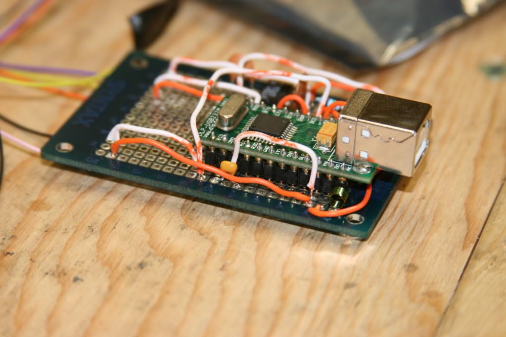
After that.. Pick up
Bread board
555 timer (radio shack)
a 47.5k resistor
2 1k resistors
and a 100nf capactor (has 104 on it)
Build the timer circuit using the same source for vcc and ground as your main circuit and that should make the nessicary 150 hz signal for the ‘watch dog’ signal.
Attach your circuit to the board as shown here.. 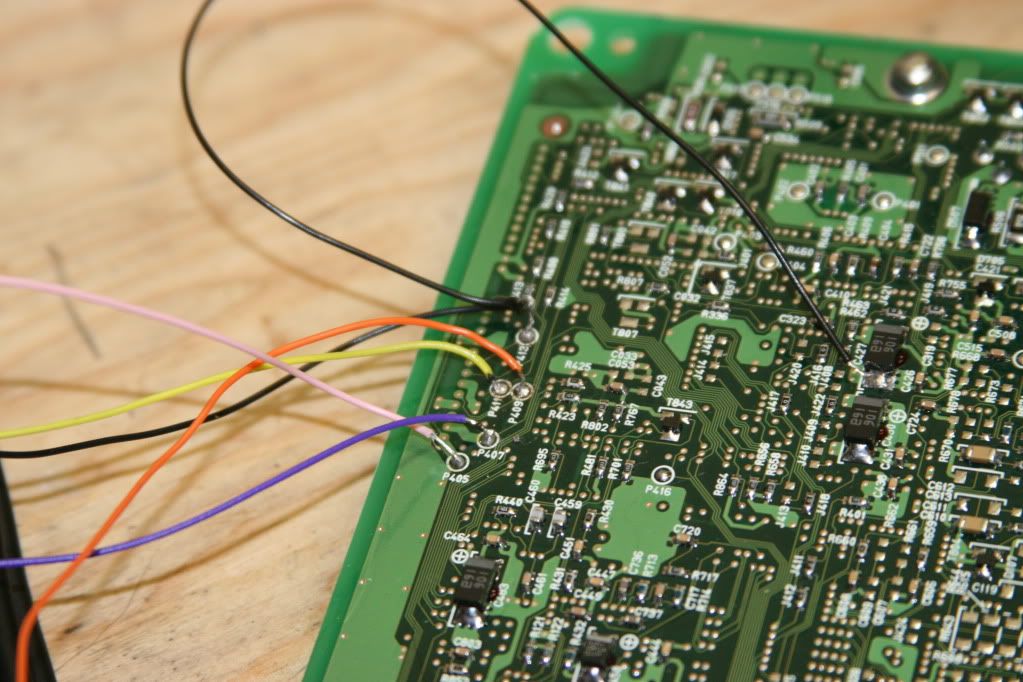
p405 (pink) is VCC
p407 (purple) is the 150 hz 555 timer signal
p409 (orange) is TX
p411 (yellow) is RX
p413 (black) is ground.. this also goes to one side of the capacitor as shown.
After a lot of cursing you should have the following.

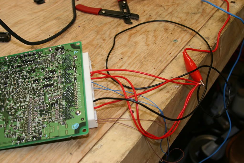
The ecu also needs to be powered up via a car battery or power supply. I powered up a lot of pins and when properly powered the ecu should draw around 400 ma of current.
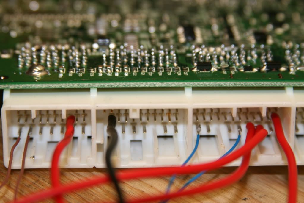
Thick wires are 12v (incl black wire) and thin wires are ground. Hook up to power like so.. (this was an 04 ecu so check your own wiring diagram to see which ones need to be powered up on yours)
Now.. Tactrix’s website tells you to use their application to recover the ecu.. It would not work for me. Some ppl can get it to work but with this setup I had to go a slightly different route.
Trying ecu flash generated this message:
[22:16:12.954] Using interface USB Serial
[22:16:14.839] sending bit rate sync bytes.
[22:16:14.839] received bit rate adjust response
sending boot command
[22:16:15.370] received bit rate adjust response
sending boot command
[22:16:15.900] received bit rate adjust response
sending boot command
[22:16:16.431] received bit rate adjust response
sending boot command
etc. it didnt work..
Sign up and download the fdt application.
Run developer toolkit basic and search for your renesas ecu in the list.. this one was the 7055. Its written on top of the biggest chip on the ecu.
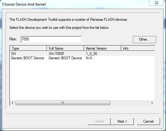
After that you will be here..
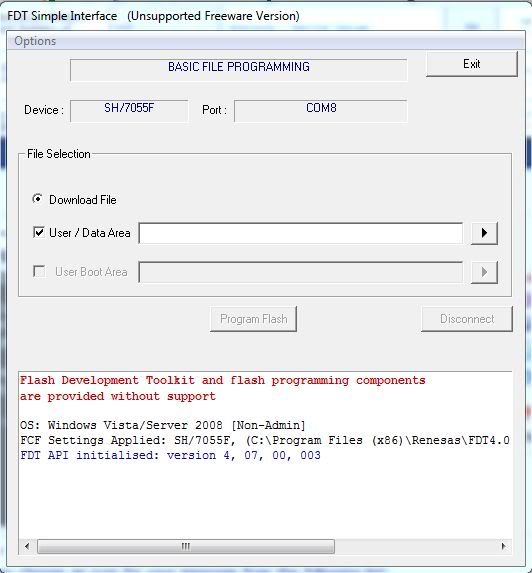
To load your tune (.hex file) into the application you must change the .hex extension to .bin. Before clicking ‘program flash’ its just like flashing the ecu in the car you must time the click the button a split second after you apply power to the ecu. If you succeed you will be rewarded with the following:
Clock Frequency (External) = 10.0000MHz, Clock Mode = 0, CKM = 4, and CKP = 2
Connecting to device ‘SH7055F’ on ‘COM8’
Configuration
‘BOOT Mode’ connection — using emulated interface
Opening port ‘COM8’ .
Loading Comms DLL
Loaded Comms DLL
Initiating BOOT SCI sequence
Attempting 9600
Received immediate response from device 0xAA
Using micro-Kernel ‘CProgram Files (x86)RenesasFDT4.07kernelsProtB7055Renesas1_0_00uG en7055r.cde’
Downloading and verifying micro kernel.
Device is erasing.
Erase Timeout value set to 21 seconds
Erase Successful
micro-Kernel download successful
Sending inquiry for getting line size
Buffer size has been set to default (128 bytes)
Sending selection of device command
Selection of Device — Device selected, code 0405
Sending selection of clock mode
Sending selection of clock mode
Selection of Clock Mode — Clock selected, code 0
Changing baud rate to 38400 bps
Set baud rate value = 38400
Downloading main kernel ‘CProgram Files (x86)RenesasFDT4.07kernelsProtB7055Renesas1_0_00Ge nm7055.cde’
Main kernel download complete.
Connection complete
Processing file CUsersFrankDesktop2004 STI LC+FFS cobb settings.bin
Loading image file ‘CUsersFrankDesktop2004 STI LC+FFS cobb settings.bin’
Operation on User Flash
Downloaded the operation module
Writing image to device. [0x00000000 — 0x00000B7F]
Writing image to device. [0x00000F80 — 0x00001EFF]
Writing image to device. [0x00001F80 — 0x0005FE7F]
Writing image to device. [0x0005FE80 — 0x0007D97F]
Writing image to device. [0x0007E700 — 0x0007E77F]
Writing image to device. [0x0007FA80 — 0x0007FAFF]
Writing image to device. [0x0007FB80 — 0x0007FFFF]
Data programmed at the following positions
0x00000000 — 0x00000B7F Length 0x00000B80
0x00000F80 — 0x00001EFF Length 0x00000F80
0x00001F80 — 0x0005FE7F Length 0x0005DF00
0x0005FE80 — 0x0007D97F Length 0x0001DB00
0x0007E700 — 0x0007E77F Length 0x00000080
0x0007FA80 — 0x0007FAFF Length 0x00000080
0x0007FB80 — 0x0007FFFF Length 0x00000480
502.63 K programmed in 609 seconds
Image written to device
Disconnecting
Disconnected
Holy crap it worked! Remove the connections from the ecu and put it back in the car. Enjoy your non bricked ecu.
I’ll add to this post if I left anything out.
If you need help building this rig or want me to try and unbrick your ecu for you just send me a pm and I will be happy to help you out!
Источник
| Автор |
|
|||
|---|---|---|---|---|
|
Заголовок сообщения: Re: Прошивка микома типа Renesas H8S
|
||||
Сообщения: 341 |
Подниму старую тему,иногда таки нужно оживить ноут-старичка |
|||
|
|
|
|||


 )
)|
Away |
Заголовок сообщения: Re: Прошивка микома типа Renesas H8S
|
|
Сообщения: 1268 |
В случае если MICOM жив, а сам биос мертв, поднять биос через TTL не получится? Последний раз редактировалось Away 15 окт 2014, 20:24, всего редактировалось 1 раз. |
|
|
|
|
Rom |
Заголовок сообщения: Re: Samsung R528 восстановление прошивки в микоме!
|
|
Сообщения: 1807 |
Rom писал(а): На сайте производителя есть софт, в даташитах — описание процесса.
|
|
|
|
|
Away |
Заголовок сообщения: Re: Samsung R528 восстановление прошивки в микоме!
|
|
Сообщения: 1268 |
Rom писал(а): Rom писал(а): На сайте производителя есть софт, в даташитах — описание процесса. Не знаю кому был ответ, но на всякий случай спрошу: Производитель чего? Опишу свою проблему. |
|
|
|

|
Rom |
Заголовок сообщения: Re: Прошивка микома типа Renesas H8S
|
|
Сообщения: 1807 |
Производитель контроллера очевидно- Renesas.
|
|
|
|
|
avtomaher |
Заголовок сообщения: Re: Прошивка микома типа Renesas H8S
|
|
Сообщения: 0 |
Прошил H8F 2110BV на ноутбуке samsung R418. (Запорол MICOM при неправильной его прошивке из windows из-за сраного Samsunga и касперского).
У вас нет доступа для просмотра вложений:
|
|
|
|
|
NightPrizrak |
Заголовок сообщения: Re: Прошивка микома типа Renesas H8S
|
|
Сообщения: 90 |
Отпишусь и я, с маленьким дополнением. |
|
|
|

|
paulleshchenko |
Заголовок сообщения: Re: Прошивка микома типа Renesas H8S
|
|
Сообщения: 412 |
Прошу помощи в прошивке H8S-2110BV viewtopic.php?f=42&t=27900 Samsung NP-R58Y (PRAHA-SRI-6L) не включается
прошиваю через |
|
|
|
|
igils |
Заголовок сообщения: Re: Прошивка микома типа Renesas H8S
|
|
Сообщения: 10986 |
Так если 23 нога (P92) реально на землю звонится даже отпаянная от платы, то его не шить надо, а менять.От перепрошивки она не отлипнет с земли. А вот после замены, если новый или не снятый с такой-же платы, надо шить. |
|
|
|
|
paulleshchenko |
Заголовок сообщения: Re: Прошивка микома типа Renesas H8S
|
|
Сообщения: 412 |
igils писал(а): Так если 29 нога реально на землю звонится даже отпаянная от платы, то его не шить надо, а менять.От перепрошивки она не отлипнет с земли. А вот после замены, если новый или не снятый с такой-же платы, надо шить. не соглашусь!!! гляньте внимательней даже по даташиту платы 92 нога на земле, пробовал шить без нее без безрезультатно, прочитав весь пост вдоль и поперек нашел что нужно соединить землю (минус) прошивальщика (MAX232) с землей платы ноута, может это повлиять на результат? |
|
|
|
|
Rom |
Заголовок сообщения: Re: Прошивка микома типа Renesas H8S
|
|
Сообщения: 1807 |
paulleshchenko писал(а): нужно соединить землю (минус) прошивальщика (MAX232) с землей платы ноута, может это повлиять на результат? конечно нужно.. а как иначе
|
|
|
|
|
paulleshchenko |
Заголовок сообщения: Re: Прошивка микома типа Renesas H8S
|
|
Сообщения: 412 |
Rom писал(а): конечно нужно.. а как иначе ну от батарейки 18650 + и — |
|
|
|
|
Rom |
Заголовок сообщения: Re: Прошивка микома типа Renesas H8S
|
|
Сообщения: 1807 |
Батарейка или нет, а землю соединять надо все-рано.
|
|
|
|
|
paulleshchenko |
Заголовок сообщения: Re: Прошивка микома типа Renesas H8S
|
|
Сообщения: 412 |
Не получается На Tx-2.36v Rx-0.39v В таком режиме потребление 0,02А |
|
|
|
|
makarog |
Заголовок сообщения: Re: Прошивка микома типа Renesas H8S
|
|
Сообщения: 802 |
igils писал(а): Так если 23 нога (P92) реально на землю звонится даже отпаянная от платы, то его не шить надо, а менять.От перепрошивки она не отлипнет с земли paulleshchenko писал(а): не соглашусь!!! гляньте внимательней даже по даташиту платы 92 нога на земле paulleshchenko, вы разницу понимаете между названием сигнала P92 и физическим номером 92, который VSS? А то вам про одно, а вы, не соглашаясь — про другое. |
|
|
|
|
igils |
Заголовок сообщения: Re: Прошивка микома типа Renesas H8S
|
|
Сообщения: 10986 |
Т.е. и коммутация для прошивки делается в том же духе? — 90, 91, 92 физические ноги на +3,3в соединяются? Чего тогда удивляться результату? |
|
|
|
|
Plextor |
Заголовок сообщения: Re: Прошивка микома типа Renesas H8S
|
|
Сообщения: 55 |
Прошиваю H8S, прога пишет «connection complete», а после висит на «Erasing 6 blocks from device», можно ли с точностью утверждать что micom под замену ? |
|
|
|
|
alien_2005 |
Заголовок сообщения: Re: Прошивка микома типа Renesas H8S
|
|
Сообщения: 795 |
Господа, а вот у меня сейчас на руках вариант посложнее, ThinkPad и у него мульт H8S/2113 Кто нибудь имел дело с этими гадами? даташит http://documentation.renesas.com/doc/pr … 8s2113.pdf стр 38
|
|
|
|
|
fekaloid |
Заголовок сообщения: Re: Прошивка микома типа Renesas H8S
|
|
Сообщения: 25 |
Ну наконецто и я его прошил после долгих танцев с бубном |
|
|
|

|
FedorovV |
Заголовок сообщения: Re: Прошивка микома типа Renesas H8S
|
|
Сообщения: 189 |
А кто нибудь прошивал H8S на hainan3_ext? День убил так и не законнектил пару купленных мультов. Да же при условии (MD0 and MD1 = GND), (P90,P91,P92= VCC), (P84=>TXD;P85=>RXD) плата никакую световую индикацию не дает, хотя тут писали у кого зеленый у кого оранжевый. При этом плата стартует (светодиоды зеленые горят) но нет изо, со старым H8S вообще не было питания CPU. |
|
|
|
|
igils |
Заголовок сообщения: Re: Прошивка микома типа Renesas H8S
|
|
Сообщения: 10986 |
FedorovV писал(а): Думаю что косяк с адаптером Эхо в терминале? |
|
|
|
|
FedorovV |
Заголовок сообщения: Re: Прошивка микома типа Renesas H8S
|
|
Сообщения: 189 |
igils писал(а): FedorovV писал(а): Думаю что косяк с адаптером Эхо в терминале? Нет. Так данная плата должна как то показывать что в находится в boot режиме? Ноги не поднимал. Какие надо на землю положил, к другим 3.3 подтянул, кварц работает. |
|
|
|
 цепляю на нужный порт и тишина, ни лампочка (TX) ни осциллографом даже активности на передачу нет. Хотя через «железный» RS-232 (COM1) и адаптере на MAX эхо есть. Но с ним почему то не хочет работать софт Renesas, пишет ошибка коммуникации с настройками игрался. С другой стороны на USB адаптере есть и индикация и запросы по TX.
|
igils |
Заголовок сообщения: Re: Прошивка микома типа Renesas H8S
|
|
Сообщения: 10986 |
Кнопку RES на миком вешали / нажимали при включении? |
|
|
|
|
FedorovV |
Заголовок сообщения: Re: Прошивка микома типа Renesas H8S
|
|
Сообщения: 189 |
Да как только не нажимал. Я честно все темы и ссылки прочитал более одного раза, так что все что описано я пробовал. |
|
|
|
|
igils |
Заголовок сообщения: Re: Прошивка микома типа Renesas H8S
|
|
Сообщения: 10986 |
Если терминал работает, то можно уточнить про отладочный режим в документации на конкретный контроллер (H8S — общее название). Не уверен — но вполне может отличаться у разных серий. |
|
|
|
|
FedorovV |
Заголовок сообщения: Re: Прошивка микома типа Renesas H8S
|
|
Сообщения: 189 |
В интерфейсе Com1 — MAX232 я не сомневаюсь, это бокс (не эмуль), я им куеву тучу тел. и не только прошил по FBUS и MBUS. Вот новый на CP2102 мне не понравился. |
|
|
|
|
eal84 |
Заголовок сообщения: Re: Прошивка микома типа Renesas H8S
|
|
Сообщения: 38 |
Ноутбук Samsung r510 Самой большой проблемой было найти прошивку. Итог на кнопку включения и выключения (5с) реагирует, но при этом питание на проц не подаётся.
У вас нет доступа для просмотра вложений:
|
|
|
|
|
jack5585 |
Заголовок сообщения: Re: Прошивка микома типа Renesas H8S
|
|
Сообщения: 112 |
Тоже столкнулся с h8s2110. Ноут samsung np-r710(geneva2_ext), 23 нога микома была пробита на землю. На плате новый миком прошить не удалось, впаял его на плату от samsung r25, подключил все по инструкции, но утилита не подключалась к контроллеру выдавая разные ошибки. Проблема оказалась в согласовании уровней сигнала железного сом порта и h8s. Переходник usb-com pl2303 решил проблему, все прошилось сразу. Как уже писали выше в теме, уровень сигнала 3.3в обязательно. Кстати светодиод при входе в бут режим горел оранжевым. |
|
|
|
|
bolta |
Заголовок сообщения: Re: Прошивка микома типа Renesas H8S
|
|
Сообщения: 23 |
Метод работает, только допольнительно подал 3,3В с программатора (Atmega48 usb-uart) на 36 ногу. Подключил программатор, подал питание на материнку (samsung r710, NP-R710-AS01EE, geneva2_ext, BA41-00936A) reset и connect поехал. Из прошивки для активации win7 не прокатило, только 11SV_M.BIN родного биоса. У меня другая засада — BIOS не могу подобрать, включается, на температуру крутит вентилятором, но дальше тишина. Биосы зашивал разные, и сам FF в оригинальный добавлял, не помогает…
У вас нет доступа для просмотра вложений:
|
|
|
|
|
mosfet666 |
Заголовок сообщения: Re: Прошивка микома типа Renesas H8S
|
|
Сообщения: 392 |
Перед запуском прошивальшика H8s надо просто коротнуть reset на землю и все прошьется без ошибок |
|
|
|
Error No. Error Message Description Appendix Error Messages 15024 Error No. 15024: Boot failed The FDT has encountered a timeout error because the device was not in boot mode or communications between the device and host computer failed. Check the following points. • Connection between the device on the target board and host computer — Communications may fail if a USB-RS232C converter, self-produced cable, self-produced extension cable <strong>for</strong> connection to the E8a*, etc. is in use. • Device on the target board — Check the voltage of the power supply <strong>for</strong> the device on the target board. — Make sure that the boot-mode and pin-handling settings <strong>for</strong> the device are correct. — Make sure that the device selection is correct. *Note: Correct operation of the E8a is only guaranteed with the cable included in the E8a package. 15025 Error No. 15025: Erase failed Erasing data in the flash memory in the device has failed. The following reasons <strong>for</strong> this error are possible. (a) A correct power-supply voltage was not being supplied to the device (from the E8a or target board). (b) The device was not operating correctly due to pin settings. (c) The device has been damaged. (d) Commands were not executed because of failed communications between the device and host computer*. Be sure to check <strong>for</strong> conditions (a) to (d). *Communications may fail when a USB-RS232C converter, self-produced cable, self-produced extension cable <strong>for</strong> connection to the E8a, etc. is in use. R20UT0508EJ1100 Rev.11.00 Page 212 of 216 Mar 07, 2012
Error No. Error Message Description Appendix Error Messages 15031 Error No. 15031: Erase failed When the device is activated in boot mode, the FDT erases the data in the flash memory. This error indicates that erasure has failed. (a) A correct power-supply voltage was not being supplied to the device (from the E8a or target board). (b) The device was not operating correctly due to pin settings. (c) The device has been damaged. Be sure to check <strong>for</strong> conditions (a) to (c). 15026 15060 15061 Error No. 15026: Unable to open comms Error No. 15060: Error while opening the port Error No. 15061: Error while closing the port 16129 Error No. 16129: Unable to download main kernel — Invalid End of Setting Data Response Received 16148 Error No. 16148: Kernel Error Response: 0xbf 0x24 Baud Rate change failed — check clock and baud rate compatibility The FDT was unable to recognize the communications port. Check the port settings <strong>for</strong> the host computer you are using. When we get inquiries regarding this error, in many cases it is because the host computer is not compatible with RS232C, leading to (a) a USB-RS232C converter being in use or (b) a serial-USB conversion IC and a self-produced conversion circuit (board) being in use. Unlike the RS-232C interface of a host computer, ports are controlled via the USB in cases (a) and (b), so the communications timing is slightly delayed. This may hamper the adjustment of timing between the FDT and device on the target board. To avoid this problem, use a host computer that is compatible with RS232C or an E8a that is connectable to the host computer via USB. An illegal command was received in the state of waiting <strong>for</strong> a data-setting completion command. Check the model name and pin settings of the device on the target board. The newly specified baud rate is illegal (the size of the error in the bit rate <strong>for</strong> serial communications is too big). Make appropriate settings <strong>for</strong> the input clock frequency, multiplier <strong>for</strong> the main clock frequency, and multiplier <strong>for</strong> the peripheral clock frequency in the [Device Settings] dialog box. When we get inquiries regarding this error, in many cases it is due to the selection of an inappropriate multiplier <strong>for</strong> the peripheral clock frequency. For details on clock supply, refer to the hardware manual <strong>for</strong> the device in use. Also check the clock settings <strong>for</strong> the device on the target board. R20UT0508EJ1100 Rev.11.00 Page 213of 216 Mar 07, 2012
- Page 1 and 2:
Renesas FLASH Development Toolkit 4
- Page 3 and 4:
Table of Contents i. Cautions …..
- Page 5 and 6:
3.5.16 Generic Boot Reinterrogate o
- Page 7 and 8:
6.1.2 Tiling windows……………
- Page 9 and 10:
7.8 Help Menu …………………
- Page 11 and 12:
8.9.2 New… ………………….
- Page 13 and 14:
11.2.2 Exit …………………..
- Page 15 and 16:
i. Cautions i. Cautions Renesas nei
- Page 17 and 18:
About this guide ii. Preface ii. Pr
- Page 19 and 20:
iii. Abbreviations iii. Abbreviatio
- Page 21 and 22:
iv. Document Conventions This manua
- Page 23 and 24:
Chapter 1 Introduction Chapter 1 In
- Page 25 and 26:
Chapter 2 System Overview Chapter 2
- Page 27 and 28:
Chapter 2 System Overview which a s
- Page 29 and 30:
Edit toolbar Save File — saves the
- Page 31 and 32:
S Record / Data File toolbar View a
- Page 33 and 34:
Find in Files — finds selected data
- Page 35 and 36:
2.3 Hot Keys Chapter 2 System Overv
- Page 37 and 38:
3.1 Quickstart Chapter 3 Using FDT
- Page 39 and 40:
Chapter 3 Using FDT Note: * Note th
- Page 41 and 42:
Chapter 3 Using FDT 3.2.6 Can I use
- Page 43 and 44:
3.3 Starting FDT 3.3.1 Starting FDT
- Page 45 and 46:
3.3.9.2. Opening workspace files fr
- Page 47 and 48:
3.4 Creating a New Workspace and Pr
- Page 49 and 50:
Supplementary: Chapter 3 Using FDT
- Page 51 and 52:
E8a Debug Interface with E8a E8 Deb
- Page 53 and 54:
Supplementary: Chapter 3 Using FDT
- Page 55 and 56:
Chapter 3 Using FDT Note that ‘Use
- Page 57 and 58:
Figure 3-9 E8aDirect Pin Settings C
- Page 59 and 60:
Figure 3-11 E20Direct Pin Settings
- Page 61 and 62:
Figure 3-13 E8aDirect RESET Pin Set
- Page 63 and 64:
Figure 3-15 E20Direct RESET Pin Set
- Page 65 and 66:
3.5.2 Generic Boot — Choose Device
- Page 67 and 68:
(2) When using a device that suppor
- Page 69 and 70:
3.5.4 Generic Boot — E8Direct Pin S
- Page 71 and 72:
Figure 3-23 Select USB Device 3.5.5
- Page 73 and 74:
3.5.6 Generic Boot — E1Direct Pin S
- Page 75 and 76:
Figure 3-30 E20Direct Generic Devic
- Page 77 and 78:
3.5.9 Generic Boot Select Device Ch
- Page 79 and 80:
3.5.11 Generic Boot Setup Complete
- Page 81 and 82:
3.5.17 Prior Generic Device Chapter
- Page 83 and 84:
• Supply power from E8/E8a/E1 to
- Page 85 and 86:
3.7 Programming the Data to the FLA
- Page 87 and 88:
3.8 Erasing Data from the FLASH ROM
- Page 89 and 90:
Figure 3-42 Upload Image Dialog Tre
- Page 91 and 92:
4.1 Wait For Script Overview Chapte
- Page 93 and 94:
4.2.1.3. Timings Chapter 4 Wait For
- Page 95 and 96:
4.2.4 Error Handling Page This is a
- Page 97 and 98:
4.3 Wait For Script — Edit Configur
- Page 99 and 100:
4.5.2 Connect Description = connect
- Page 101 and 102:
Chapter 4 Wait For Script Note that
- Page 103 and 104:
Example: Erase 0|1|4|7 Erase EB0|EB
- Page 105 and 106:
4.5.8 Disconnect Chapter 4 Wait For
- Page 107 and 108:
4.5.13 Delete Chapter 4 Wait For Sc
- Page 109 and 110:
4.5.17 Unlock Chapter 4 Wait For Sc
- Page 111 and 112:
4.6 Wait For Script — Example Scrip
- Page 113 and 114:
Chapter 4 Wait For Script When FDT
- Page 115 and 116:
5.3 Access Rights Administration Th
- Page 117 and 118:
5.3.3 Add User Chapter 5 Access Rig
- Page 119 and 120:
6.2 Locating Currently Open Windows
- Page 121 and 122:
Chapter 6 Configuring the User Inte
- Page 123 and 124:
7.1.4 Save Workspace Saves the deta
- Page 125 and 126:
7.2.9 Replace… Chapter 7 Menus Th
- Page 127 and 128:
7.4.5.1. File Extensions Add… Sel
- Page 129 and 130:
7.5 Tools Menu Chapter 7 Menus The
- Page 131 and 132:
7.6.6 ‘file name’ This option b
- Page 133 and 134:
7.8 Help Menu Chapter 7 Menus The
- Page 135 and 136:
Chapter 8 Windows Chapter 8 Windows
- Page 137 and 138:
8.1.2 Project Chapter 8 Windows The
- Page 139 and 140:
8.1.3 Device Image — Folder Chapter
- Page 141 and 142:
8.2.3 Remove Files… Removes files
- Page 143 and 144:
8.3 Workspace Properties Invoked fr
- Page 145 and 146:
8.5 Configure Flash Project (Flash
- Page 147 and 148:
8.5.2 Communications Tab Chapter 8
- Page 149 and 150:
Device Figure 8-10 Device Propertie
- Page 151 and 152:
8.5.4 Programmer Tab Chapter 8 Wind
- Page 153 and 154:
File Over Warning Chapter 8 Windows
- Page 155 and 156:
8.6.2 Cursor Value Chapter 8 Window
- Page 157 and 158:
8.7.3 Save Chapter 8 Windows Allows
- Page 159 and 160:
Chapter 8 Windows files (and upload
- Page 161 and 162:
8.8.8 Align to 8 Bytes Chapter 8 Wi
- Page 163 and 164:
8.9 Customise — Toolbars Invoked by
- Page 165 and 166:
8.10 Customise — Menu Chapter 8 Win
- Page 167 and 168:
To modify a menu option: Chapter 8
- Page 169 and 170:
Chapter 9 Simple Interface Mode Cha
- Page 171 and 172:
9.1.8 File Over Warning Chapter 9 S
- Page 173 and 174:
Chapter 9 Simple Interface Mode 9.2
- Page 175 and 176:
Chapter 10 Basic Simple Interface M
- Page 177 and 178:
10.1.8 File Over Warning Chapter 10
- Page 179 and 180:
Chapter 10 Basic Simple Interface M
- Page 181 and 182:
Chapter 11 Field Programming Chapte
- Page 183 and 184: 11.1 Options Menu 11.1.1 Login… C
- Page 185 and 186: 11.2 Dialog Controls 11.2.1 Back to
- Page 187 and 188: Chapter 12 Updating the Adapter Sof
- Page 189 and 190: Level 1 only update: Chapter 12 Upd
- Page 191 and 192: Chapter 13 Interface Boards Chapter
- Page 193 and 194: 13.3 E1 (incorporating E1Direct) Ch
- Page 195 and 196: 13.5 E8 Firmware and Device ID When
- Page 197 and 198: 13.6 Pins Chapter 13 Interface Boar
- Page 199 and 200: 26 — 27 — 28 — 29 — 30 — 31 — 32 —
- Page 201 and 202: Chapter 14 QzROM Programming Chapte
- Page 203 and 204: 15.1 Locking Overview Chapter 15 Lo
- Page 205 and 206: 15.3 Locking Dialog Chapter 15 Lock
- Page 207 and 208: State at Disconnect Chapter 15 Lock
- Page 209 and 210: 2. Query User Chapter 15 Locking If
- Page 211 and 212: Chapter 16 Unique Code Programming
- Page 213 and 214: 16.1.3 File Start Point Chapter 16
- Page 215 and 216: 16.2.2 Code Section Chapter 16 Uniq
- Page 217 and 218: 17.1 QzROM Devices Chapter 17 ROM C
- Page 219 and 220: Chapter 17 ROM Code Protection Note
- Page 221 and 222: 17.2 R32C Devices Chapter 17 ROM Co
- Page 223 and 224: 17.2.2 Project Chapter 17 ROM Code
- Page 225 and 226: Chapter 18 Windows Vista ® and Win
- Page 227 and 228: 19.1 Outline Chapter 19 Intelligent
- Page 229 and 230: Item Description Chapter 19 Intelli
- Page 231 and 232: Chapter 20 Upgrading to FDT 4.08 Ch
- Page 233: Appendix Error Messages Error No. E
- Page 237 and 238: Error No. Error Message Description
- Page 239 and 240: Renesas FLASH Microcomputer Program
- Page 242: Renesas FLASH Development Toolkit 4