ERROR HANDLING
By default LABVIEW automatically handles any error that occurs when a VI runs by suspending execution, highlighting the subVI or function where the error occurred, and displaying a dialog box. You can choose other error handling methods. For example, if an I/O VI on the BLOCK DIAGRAM times out, you might not want the entire application to stop. You also might want the VI to retry for a certain period of time. In LabVIEW, you can make these error handling decisions on the block diagram of the VI.
VIs and functions return errors in one of two ways—with numeric error codes or with an error cluster. Typically, functions use numeric error codes, and VIs use an error cluster, usually with error inputs and outputs. Error handling in LABVIEW follows the data flow model. Just as data flow through a VI, we get an error information. Wire the error information from the beginning of the VI to the end. Include an error handler VI at the end of the VI to determine if the VI ran without errors. Use the error in and error out clusters in each VI you use or build to pass error information through the VI.
If you would like to Enrich your career with an Android certified professional, then visit Mindmajix — A Global online training platform: “LabVIEW training” Course.This course will help you to achieve excellence in this domain.
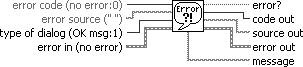
As the VI runs, LabVIEW tests for errors at each execution node. If LabVIEW does not find any errors, the node executes normally. If LabVIEW detects an error, the node passes the error to the next node without executing. The next node does the same thing and so on. Use the simple error handler VI, shown below Figure, to handle the error at the end of the execution flow. The simple error handler VI is located on the Functions» All Functions» Time & Dialog palette. Wire the error cluster to the error in input.
.png)
ERROR CLUSTER
Error clusters tell you why and where errors occur. When you perform any kind of I/O, consider the possibility that errors will occur. Almost all I/O functions return error information. Include error checking in VIs, especially for I/O operations such as file, serial, instrumentation, data acquisition, and communication operations, and provide a mechanism to handle errors appropriately. No matter how confident you are in the VI you create, you cannot predict every problem a user might encounter. Without a mechanism to check for errors, you know only that the VI does not work properly. Checking for errors in VIs can help you identify the following problems:
- You initialized communications incorrectly or wrote improper data to an external device.
- An external device lost power, is broken, or is not working properly.
- You upgraded the operating system software which changed the path to a file or the functionality of a VI or library. You might notice a problem in a VI or a system program.

Frequently Asked LabVIEW Interview Questions & Answers
The error clusters located on the Functions» All Functions» Array & Cluster palette include the following components of information which are also shown below Figure..png)
- status is a Boolean value that reports True if an error occurred. Most VIs, functions, and structures that accept Boolean data also recognize this parameter. For example, you can wire an error cluster to the Boolean inputs of the Stop, Quit LabVIEW, or Select If an error occurs, the error cluster passes a True value to the function.
- code is a 32-bit signed integer that identifies the error numerically. A non-zero error code coupled with a status of False signals a warning rather than a fatal error.
- the source is a string that identifies where the error occurred. Use the error cluster controls and indicators to create error inputs and outputs in subVIs.
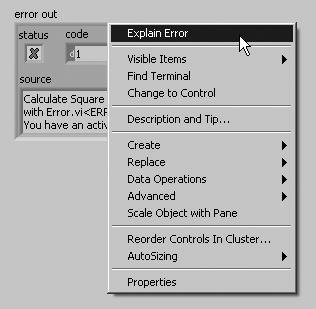
When an error occurs, right-click within the cluster border and select Explain Error from the shortcut menu to open the Explain Error dialog box. The Explain Error dialog box contains information about the error. The shortcut menu includes an Explain Warning option if the VI contains warnings but no errors. You can also access the Explain Error dialog box from the Help» Explain Error menu.
Explore LabVIEW Sample Resumes! Download & Edit, Get Noticed by Top Employers!Download Now!
About Author

Ruchitha Geebu
I am Ruchitha, working as a content writer for MindMajix technologies. My writings focus on the latest technical software, tutorials, and innovations. I am also into research about AI and Neuromarketing. I am a media post-graduate from BCU – Birmingham, UK. Before, my writings focused on business articles on digital marketing and social media. You can connect with me on LinkedIn.
 |
This article or section needs to be updated. Some information on it may be out of date, and should not be relied on. Please improve this article if you can. |
The Error Cluster is a predefined LabVIEW Cluster that is used to contain error status information. The cluster contains the following three components:
| Name | Data Type | Description |
|---|---|---|
| Status | Boolean | Indicates if an error has occurred (TRUE = error, FALSE = no error). |
| Code | 32-Bit signed integer | A standardized error code specific to the particular error. LabVIEW has a table of default error codes, although the user is able to define custom error codes. See below for more information. |
| Source | String | Textual information often describing the error and the VI it occurred within. |
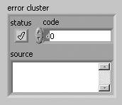
An error cluster contains a Boolean “status”, an I32 numerical “code” and a “source” string in that order. Any cluster with this structure is treated as an error cluster in LabVIEW. The default value, “status” = false, “code” = 0 and “source” empty, is shown in Figure 1 for a typical control.
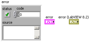
Figure 1: 3D error cluster control and terminal
Note that the default terminal and wire color was changed from pink to dark yellow in LabVIEW 8.2 (upgrade notes p. 35). The “status” is true if an error has occurred but remains false for warnings. The “code” assumes positive and negative values (see “error codes, ranges of” in LabVIEW Help).
Contents
- 1 Custom Error Codes
- 2 General Error Handling
- 2.1 Error Comparison
- 2.2 Error Selection
- 3 Error Cluster as Execution Order Specifier
- 4 Tips and tricks
- 5 See also
Custom Error Codes
The following ranges are reserved for developers to define their own error codes (see Custom Error Code):
- 5000 to 9999
- -8999 to -8000
- 500000 to 599999
Use Tools >> Advanced >> Edit Error Codes to create text files to define your own errors.
The “source” identifies a VI and possibly its call chain as the origin of an error. Possible reasons for an error can be obtained from the Explain Error tool (see Figure 2). This tool is activated by selecting the Explain Error… item under the Help menu in LabVIEW or by right-clicking on any element of an error cluster with “status” true and selecting Explain Error.
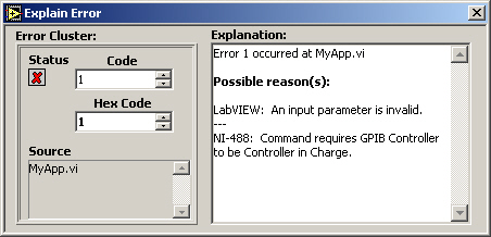
Figure 2: Explain Error tool
General Error Handling
LabVIEW provides several VIs for working with error clusters. For example, the Error Cluster from Error Code.vi generates an error cluster based on a specified “code” (see Figure 3). You can also define custom codes using the General Error Handler.vi or by creating an XML-based text file in the <labviewuser.lib errors> directory (see “error codes, defining custom” and “error codes, defining custom in text files” in LabVIEW Help). This VI outputs a “message”, like the “Explanation” from Explain Error, which identifies the “source” and describes possible causes associated with the “code”. This information can also be displayed using several different types of dialogs. This feature is commonly employed to identify errors in user interface applications.
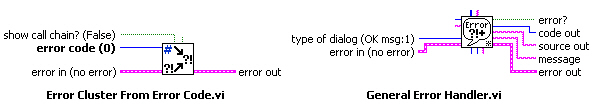
Figure 3: connectors for Error Cluster from Error Code.vi and General Error Handler.vi
Error Comparison
Error clusters are also valid inputs to some comparison and array functions and can be used to control case structures and while loops (see Figure 4).
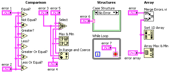
Figure 4: structures, comparison and array functions involving error cluster inputs
The comparison functions Equal?, Not Equal?, Greater?, Less?, Greater Or Equal? and Less Or Equal? can operate in two modes. The output is Boolean in the Compare Aggregates mode, while a cluster of three Booleans corresponding to each component of the error cluster is generated in the Compare Elements mode (see Figure 5).
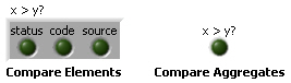
Figure 5: typical indicators for both modes of a comparison function
The Select, Max & Min and In Range and Coerce functions can output an error cluster. While the Max & Min function returns ordered inputs in the Compare Aggregates mode, an output may not correspond to either error cluster if Compare Elements is selected (default). The Array Max & Min function always returns ordered inputs corresponding to the first and last elements of the Sort 1D Array output. The primary sort is performed on “status”, with secondary ordering by “code” and then “source”. Strings are sorted by ASCII code starting with the leading character. Note that error clusters behave like their Boolean “status” value when connected to the selector terminal of a Select function and Case Structure or the conditional terminal of a While Loop.
Error Selection
A common programming issue in LabVIEW involves selecting between two or more error clusters. This process involves finding the cluster with “status” true or “code” not equal zero if no “status” is true. The Merge Errors.vi shown in Figure 4 implements this search for up to three error clusters and an array of such clusters. This subVI is relatively fast with large error arrays. However, a significant portion of the execution time involves concatenation of inputs for the small arrays (<10 elements) typical in most applications. This result suggests that time critical applications should be built around the immediate selection between two error clusters rather than their concatenation into an array. The simplest method of comparing the “status” of two error clusters involves the Select function (see Figure 6).
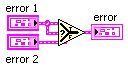
Figure 6: diagram for a simple error selector that does not detect warnings
This function selects the first error cluster with “status” true, much like the Or function operating on Boolean inputs. Connecting “error 2” instead of “error 1” to the selector terminal is more analogous to the And function, which is typically less useful. While about 30 times faster than the Merge Errors.vi (LabVIEW 7.0), the Select function does not detect a warning (“status” false and “code” not equal zero).
Diagrams for several VIs that compare error clusters and detect warnings are shown below (fastest to slowest).
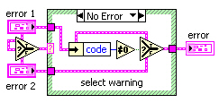
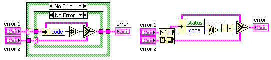
Figure 7: possible diagrams for an error selector that detects warnings
These VIs execute about 5 times faster than the Merge Errors.vi (LabVIEW 7.0), even with normal priority execution. (Merge Errors.vi uses the “subroutine” priority.) Inputs to selector terminals in the first and second diagrams are passed to “error” for the cases not shown. Otherwise, “error 1” is checked for nonzero “code” since neither cluster has “status” true. The last approach uses the Max & Min function in Compare Aggregates mode to order inputs. If just one of these clusters has “status” true, that input will be the “max” output since true > false. However, this output must be checked for “status” true or “code” nonzero to determine selection.
Error Cluster as Execution Order Specifier
LabVIEW is a dataflow language and as such preferred way to specify execution order of block diagram items is to connect output of a block diagram item to an input of another block diagram item. There are situations when some certain execution order is required but the outputs of the items to be executed earlier cannot be connected to the inputs of the items to be executed later. In these situations error cluster is a preferred way to specify the execution order of the items. It’s preferred over sequence structures in almost all use cases.
This can easily be achieved by a private replacement for the ‘merge errors’ node, that also contains a ‘No_Error’ constant:
 The connector pane looks like this:
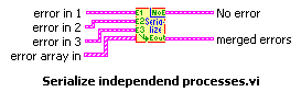
It can be used like this:
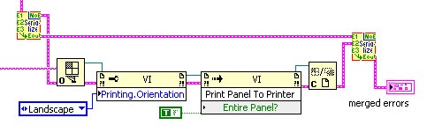
So a VI-Ref is opened independently if an error occured before, but after all preliminary portions of code had been finished. The printing actions relate to the eventual error of the OpenVI-Ref node only. All errors are merged as final action, so any error that might have shown up is reported, while the printing actions care only on VI-server related errors.
This little helper is too simple to provide its code as VI, though…
Tips and tricks
- Right-click the status button inside an error cluster on the front panel and select Explain Error to open the Explain Error dialog.
See also
- Error handling
- Error Case Structure
да/вывода, от коммуникационных устройств) и обеспечьте механизм для соответствующей обработки ошибок.
Проверка на ошибки в ВП может помочь Вам определить следующие проблемы:
•Некорректная инициализация коммуникаций или запись неверных данных во внешнее устройство.
•Внешнее устройство, лишившись питания, становится неисправным или работает неправильно.
•Произошло обновление операционной системы, в результате чего изменились пути к файлам или библиотекам. Вы же будете считать, что проблема в ВП или в системной программе.
Обработка ошибок
По умолчанию LabVIEW автоматически обрабатывает ошибки посредством приостановки выполнения. Вы можете выбрать другой метод обработки ошибок. Например, если ВП ввода/вывода на блок-диаграмме находится в ожидании, Вы можете не захотеть останавливать все приложение. Вы можете пожелать, чтобы ВП сделал повторную попытку через некоторое время. В LabVIEW можно реализовать на блок-диаграмме ВП такой вариант обработки ошибки.
ВП и функции возвращают ошибки одним из двух способов – в виде цифрового кода ошибки или в виде кластера ошибки. Как правило, функции используют числовой код ошибки, а ВП – кластер ошибки, обычно с ошибками на входах и на выходах. Более подробно о кластерах ошибок см. в разделе Кластеры ошибок в настоящей Главе.
Обработка ошибок в LabVIEW следует модели потока данных. Подобно тому, как поток данных проходит через ВП, может проходить и информация об ошибках. Передайте информацию об ошибках от начала ВП к его концу. Включите в конце этого ВП обработчик ошибок для определения того, что данный ВП работает без ошибок. Для передачи через ВП информации об ошибках используйте в каждом ВП, который Вы используете или строите, кластеры error in и error out.
131
Как только такой ВП запустится, LabVIEW будет делать проверку на ошибки в каждом исполняемом узле. Если ошибки не обнаружены, значит, данный узел выполнился нормально. Если же в узле будет обнаружена ошибка, то этот узел передаст ошибку следующему узлу без исполнения некоторой части своего кода. Следующий узел поступает таким же образом и т.д. В конце исполненного потока данных будет сообщение об этой ошибке.
Кластеры ошибок
Кластеры error in и error out содержат следующие компоненты:
•status – булева величина, которая принимает значение TRUE, если имеется ошибка. Большинство ВП, функций и структур, которые принимают булевы данные, могут использоваться для распознавания этого параметра. Например, Вы можете соединить кластер ошибок к булевым входам функций Stop, Quit LabVIEW или Select. Если имеет место ошибка, то кластер ошибок выдаст значение TRUE на входы этих функций.
•code – 32-битовой целое со знаком, которое идентифицирует ошибку ее числовым кодом. Ненулевое значение кода ошибки, сопровождаемое значением status FALSE, сигнализирует о предупреждении, а не о фатальной ошибке.
•source – строка, которая идентифицирует место возникновения ошибки.
Использование для обработки ошибок циклов While Loop
Вы можете подсоединить кластер ошибок к терминалу условия цикла While Loop, чтобы остановить итерации этого цикла. Когда Вы подсоединяете кластер ошибок к терминалу условия, то фактически на этот терминал проходят только значения TRUE или FALSE параметра status из кластера ошибок. При возникновении ошибки цикл While Loop остановится.
Когда кластер ошибок присоединяется к терминалу условия (Condition terminal), пункты контекстного меню Stop if True и Continue if True изменяются на Stop on Error и Continue while Error.
Использование для обработки ошибок структур Case
Когда Вы подсоединяете кластер ошибок к селекторному терминалу структуры Case, метки селектора отображают два случая: Error
132
и No Error, а рамка структуры Case изменяет свой цвет на красный для варианта Error и зеленый для варианта No Error. Если имеет место ошибка, структура Case выполняет поддиаграмму Error. Более подробно об использовании структуры Case см. в раз-
деле Структура Case в Главе 8 Циклы и структуры.
133
7. Создание ВП и ВПП
После того, как Вы познакомились с построением лицевой панели и блок-диаграммы, Вы можете создавать свои собственные ВП и ВПП, распространять ВП и строить стандартные исполняемые приложения и совместные библиотеки.
Дополнительные сведения о планировании вашего проекта, включая информацию о ловушках и инструментах, которые Вы можете использовать при разработке своих проектов, содержатся в руково-
дстве LabVIEW Development Guidelines.
Более подробно…
Более подробно относительно создания и использования ВПП, о сохранении ВП и построении стандартных приложений и совместных библиотек см. в справочной системе LabVIEW Help.
Планирование и построение вашего проекта
Перед разработкой ваших собственных ВП создайте перечень задач, которые ваши пользователи должны будут выполнять. Определите компоненты пользовательского интерфейса, количество и типы элементов управления и индикаторов, которые потребуются для анализа данных, отображения результатов и т.п. Продумайте и обсудите с предполагаемыми пользователями или коллегами по проекту, как и когда пользователям потребуется доступ к функциям и возможностям. Создайте простую лицевую панель, чтобы продемонстрировать ее пользователям или коллегам и определить, помогает ли такая лицевая панель решать их задачи. Используйте такой процесс взаимодействия для улучшения пользовательского интерфейса.
Разделите ваше приложение на логические части легко управляемого размера. Начните с блок-диаграммы верхнего уровня, которая включает основные компоненты вашего приложения. Например, блок-диаграмма может включать блок конфигурации, блок ввода данных, блок обработки данных, блок отображения результатов, блок сохранения данных на диск и блок обработки ошибок.
134
После создания блок-диаграммы верхнего уровня определите входы и выходы. Затем создавайте ВПП, которые реализуют основные компоненты блок-диаграммы верхнего уровня. Использование ВПП делает блок-диаграмму верхнего уровня легкой для чтения, отладки, понимания и сопровождения. Вы также можете создавать ВПП для типовых и часто используемых операций, которые используются в нескольких местах. Сразу после создания ВПП проверяйте их. Вы можете создавать тестовые процедуры высокого уровня, однако выловить ошибки в небольшом модуле гораздо легче, чем тестировать иерархию из нескольких ВП. Вы можете обнаружить, что начальное проектирование блок-диаграммы высокого уровня является неполным. Использование ВПП для реализации сложных задач обеспечивает легкость модификации или реорганизации вашего приложения. Более подробно о ВПП см. в разделе
Виртуальные подприборы в этой Главе.
Выберите Help»Find Examples для ознакомления с примерами блок-диаграмм и ВПП.
Разработка проектов несколькими разработчиками
Если над одним проектом работают несколько разработчиков, то с самого начала определяйте обязанности по программированию, стандарты на интерфейсы и кодирование, чтобы гарантировать успешность процесса проектирования и хорошую совместную работу приложения. Более подробно о стандартах кодирования см. в раз-
деле 6 LabVIEW Style Guide руководства LabVIEW Development Guidelines.
Сохраняйте оригиналы проекта ВП на одном компьютере и установите политику управления исходными кодами. Рассмотрите ис-
пользование пакета LabVIEW Professional Development System, ко-
торый включает инструменты управления исходными кодами, упрощающие совместное пользование файлами. Эти инструменты включают также утилиту для сравнения виртуальных приборов и просмотра различий между версиями. Более подробно об управлении исходными кодами см. в разделе Source Code Control в Главе 2
Incorporating Quality into the Development Process в руководстве Development Guidelines.
135

Шаблоны ВП
Шаблоны виртуальных приборов (VI templates) включают ВПП, функции, структуры и объекты лицевой панели, которые могут потребоваться Вам, чтобы начать строить типовые измерительные приложения. Шаблоны ВП открываются как виртуальные приборы с именем «безымянный» (untitled), которые затем нужно сохранить. Выберите File»New для отображения диалогового окна New, которое содержит имеющиеся шаблоны ВП. Вы также можете отобразить диалоговое окно New, выбирая пункт New из выпадающего меню New главного диалогового окна LabVIEW.
Если Вы используете шаблон ВП в качестве ВПП, LabVIEW предложит Вам сохранить шаблон как ВП перед его закрытием.
Создание шаблонов ВП
Создавайте пользовательские шаблоны ВП, чтобы исключить необходимость помещать одни и те же компоненты на лицевые панели или блок-диаграммы всякий раз, когда Вы создаете новые ВП. Чтобы создать пользовательский шаблон ВП, постройте ВП и сохраните его как шаблон (template).
Другие типы документов
Выберите соответствующий пункт раздела Other Documents Types в перечне Create New диалогового окна New, чтобы начать создавать глобальные переменные, пользовательские элементы управления, меню времени исполнения, полиморфные ВП или шаблоны для глобальных переменных и элементов управления.
Использование встроенных ВП и функций
Чтобы помочь Вам создавать свои специфические приложения, LabVIEW содержит ВП и функции, обеспечивающие ввод/вывод, доступ к другим ВП и связь с другими приложениями. Вы можете использовать эти и ВП и ВПП в ваших приложениях для ускорения их разработки. Более подробно о ВПП см. в разделе Виртуальные подприборы (ВПП) в настоящей Главе.
136
Построение ВП и функций для управления приборами и ввода/вывода данных
LabVIEW включает сотни примеров ВП, которые Вы можете использовать и встраивать в создаваемые вами ВП. Вы можете или модифицировать ВП из примера и адаптировать его к вашему приложению, или копировать фрагменты из одного или нескольких примеров и вставлять их в свой ВП.
Вы можете использовать встроенные ВП и функции для управления внешними приборами, такими как осциллографы, или осуществлять сбор данных, например, снимая данные с термопары.
Используйте ВП и функции с палитры Instrument I/O для управления внешними приборами. Чтобы управлять приборами в LabVIEW, Вы должны иметь оборудование, правильно установленное, включенное и работающее на вашем компьютере. ВП и функции, которые Вы используете для управления приборами, зависят от протоколов связи, которые поддерживает ваше оборудование. Более подробно о построении ВП для управления приборами см. в
руководстве LabVIEW Measurements Manual.
Используйте ВП и функции с палитры Data Acquisition для ввода/вывода данных через DAQ-устройства. Чтобы использовать эти ВП, Вы должны иметь установленными программный драйвер NIDAQ и оборудование DAQ. Более подробно об инсталляции программного драйвера NI-DAQ и оборудования DAQ и о построении ВП для сбора данных см. в руководстве LabVIEW Measurements Manual. После того, как Вы введете данные, Вы можете использовать встроенные ВП и функции с палитр Analyze, Report Generation и Mathematics для обработки, генерации отчетов и выполнения математических операций над этими данными. Более подробно об основах математики и обработки данных в LabVIEW см. в руково-
дстве LabVIEW Analysis Concepts.
Построение ВП, которые имеют доступ к другим ВП
Используйте ВП и функции из подпалитры Application Control (управление приложениями) для управления поведением ВП в тех случаях, когда он вызывается как ВПП или запускается пользователем. Вы можете использовать эти ВП и функции для одновременного конфигурирования нескольких ВП. Кроме того, если Вы находитесь в локальной сети с другими пользователями LabVIEW,
137

то можете использовать эти ВП и функции для удаленного доступа и управления ВП. Более подробно об удаленном управлении ВП см. в Главе 17 Программное управление ВП.
Построение ВП, которые общаются с другими приложениями
Используйте ВП и функции с подпалитры File I/O (файловый ввод/вывод) для чтения данных из или записи данных в другие приложения, такие, например, как Microsoft Excel. Вы можете использовать эти ВП и функции для создания отчетов или внедрения данных из других приложений в ВП. Более подробно о передаче данных в другие приложения и из них см. в Главе 14 Файловый ввод/вывод.
Используйте ВП и функции из подпалитры Communication (связь) для передачи данных через сеть, используя протокол обмена вроде FTP, и построение на основе этого протокола приложений клиентсервер. Более подробно о связи с другими приложениями через локальную или глобальную сеть см. в Главе 18 Сетевые коммуника-
ции в LabVIEW.
(Windows) Используйте функции ActiveX, чтобы добавить объекты ActiveX в ВП или для управления ActiveX-совместимыми приложениями. Более подробно об использовании технологии ActiveX
см. в Главе 19 Связность в среде Windows.
Виртуальные подприборы (ВПП)
После того, как Вы построите ВП и создадите для него иконку и соединительную панель, его можно использовать внутри другого ВП. Виртуальный прибор, вызываемый с блок-диаграммы другого виртуального прибора, называется виртуальным подприбором (ВПП). ВПП соответствует подпрограмма в тестовых языках программирования. Узлу ВПП соответствует вызов подпрограммы. Этот узел не является самим ВПП, также как оператор вызова подпрограммы не является самой подпрограммой. Блок-диаграмма, которая содержит несколько одинаковых узлов ВПП, несколько раз вызывает один и тот же ВПП.
Элементы управления и индикаторы ВПП получают данные от блок-диаграммы вызывающего ВП и возвращают в нее результаты. Щелкните на палитре Functions иконку Select a VI, найдите нуж-
138
ный файл ВП, сделайте по нему двойной щелчок и поместите этот ВП на блок-диаграмму, чтобы создать ВПП, который вызывается из данного ВП.
«Примечание. Перед тем, как использовать ВП в качестве ВПП, Вы должны установить соединительную панель. Более подробно о конфигурировании соединительной панели см. в разделе Конфигурирование со-
единительной панели в настоящей Главе.
Вы можете открыть ВПП для редактирования, делая двойной щелчок по узлу ВПП на блок-диаграмме с помощью инструмента Operating или Positioning. Если Вы сохраняете ВПП, то внесенные изменения будут действовать на все вызовы данного ВПП, а не только на текущий его представитель.
Обычно, когда LabVIEW вызывает ВПП, он запускается без отображения его лицевой панели. Если Вы хотите, чтобы конкретный представитель некоторого ВПП отображал свою лицевую панель при вызове, щелкните правой кнопкой иконку ВПП и выберите из контекстного меню SubVI Node Setup. Если же Вы хотите, чтобы все представители ВПП отображали свою лицевую панель при вызове, выберите File»VI Properties, затем из спадающего меню
Category выберите Window Appearance и щелкните кнопку Customize.
Выявление однотипных операций
При создании ВП Вы можете обнаружить, что некоторые операции выполняются многократно. Рассмотрите возможность использования ВПП или циклов для повторного выполнения таких операций. Например, блок-диаграмма на Figure 7-1 содержит две одинаковые операции.
139
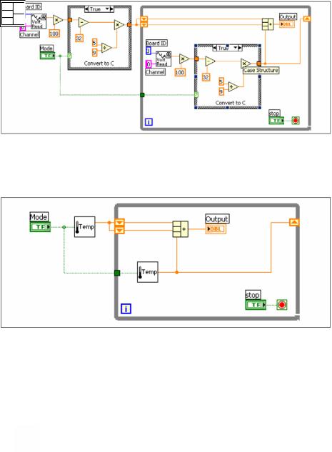
Figure 7-1. Блок-диаграмма с двумя одинаковыми операциями
Вы можете создать ВПП, который выполняет эту операцию, и затем дважды вызвать этот ВПП, как это показано на Figure 7-2.
Figure 7-2. Двукратный вызов ВПП
Кроме того, Вы можете использовать этот ВПП в других ВП. Более подробно об использовании циклов для объединения однотипных операций см. в Главе 8 Циклы и структуры.
Конфигурирование соединительной панели
Чтобы использовать ВП в качестве ВПП, Вы должны построить соединительную панель, показанную слева. Соединительная панель представляет собой набор терминалов, которые соответствуют элементам управления и индикаторам ВП, подобно списку параметров
140
Соседние файлы в папке LabView — учеб. пособия
- #
- #
- #
- #
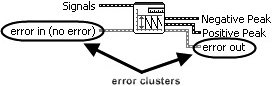
You might have already noticed the error cluster datatype, which is found on the Modern>>Array, Matrix & Cluster palette (Error In and Error Out, shown in Figure 7.64) and can also be found used in the inputs and outputs of many VIs and functions. The error cluster is a special datatype in LabVIEW (a cluster consisting of a status Boolean, code I32, and source string) that is used for propagating information about errors that occur during the execution of LabVIEW code. Errors and error handling are very naturalthere is no reason to be afraid of errors. Rather, we should understand how errors can occur, how to communicate errors, and how to handle errors.
Figure 7.64. Error In and Error Out controls found on the Array, Matrix & Cluster palette
So, what is an error? In simple terms, an error is an event where a function or subVI cannot complete a request because resources are not available or the information (arguments) passed to it are not valid.
In LabVIEW, we use dataflow to propagate information about errors inside of an error cluster datatype.
Error Cluster Datatype
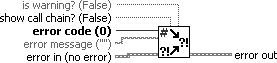
The error cluster (shown in Figure 7.65) contains three elements, as follows:
-
status BooleanSignifies whether there is an error (TRUE) or no error (FALSE).
-
code I32Is an error code signed integer that identifies the error.
-
Positive codes are errors.
-
Negative codes are warnings.
-
Zero is no error.
-
-
source stringIs a string that contains descriptive information about the source of the error. This commonly also contains a call chain, a list of VIs starting at the subVI (or function) where the error occurred and then listing up the call hierarchy, all the way up to the top-level VI.
Figure 7.65. Error cluster

Propagating Errors: Error Dataflow
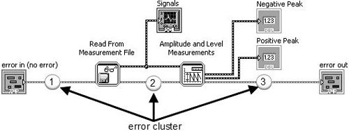
You use the error cluster datatype to store information about an error, and you use dataflow to propagate the error cluster through your block diagram. As you can see the example shown in Figure 7.66, an error cluster passes through the block diagram, connecting the following, in sequence:
-
error in control terminal to the Read From Measurement File subVI.
-
Read From Measurement File subVI to Amplitude and Level Measurements subVI.
-
Amplitude and Level Measurements subVI to the error out indicator terminal.
Figure 7.66. Block diagram showing how the error cluster is used to propagate errors using dataflow


Many of LabVIEW’s functions and VIs have error in and error out terminals. These are almost always found (if present on the function or VI) on the lower-left and lower-right terminals of the connector pane (respectively). Figures 7.67 and 7.68 show the inputs and outputs of Read From Measurement File and Amplitude and Level Measurements with error in and error out highlighted.
Figure 7.67. Read From Measurement File
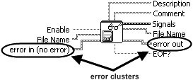
Figure 7.68. Amplitude and Level Measurements
Generating and Reacting to Errors in SubVIs
The expected behaviors of functions and VIs, with respect to generating and reacting to errors, are the following:
-
If error in contains an error (status = TRUE), do not do any work unless it is «clean up» work, such as
-
closing file references.
-
closing instrument or other communication references.
-
putting the system back into an idle/safe state (powering off motors, etc.).
-
-
If an error occurs inside of a function or VI, the function should pass out the error information via its error out indicator terminal unless it was passed in an error via its error in input terminal. In this case, just pass the incoming error from error in to error out, unchanged.
Error Case Structure
A subVI can fulfill expected behavior #1, by «wrapping» all of its functional code (its «work») inside of an Error Case Structure, which is simply a case structure that has an error cluster wired to its case selector terminal. As you can see in Figure 7.69, the Case Structure allows the error cluster datatype to be wired to its case selector terminal. When wired in this way, the Case Structure frame names change to «No Error» and «Error.» At run-time, if the error cluster does not contain an error, then the «No Error» frame will execute. Conversely, if the error cluster does contain an error, then the «Error» frame will execute.
Figure 7.69. An «Error Case Structure» containing an «Error» and «No Error» cases
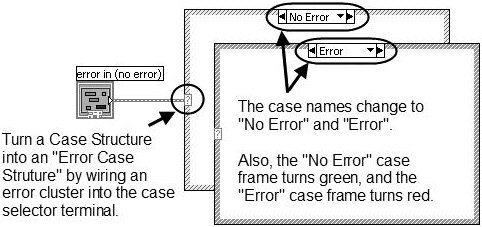
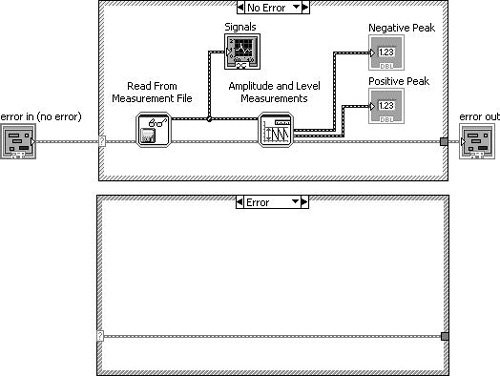
Figure 7.70 shows how we can use a case structure to conditionally execute our functional code only when there is no «upstream error» (using the dataflow vernacular).
Figure 7.70. An «Error Case Structure» used to execute code only when there is no «upstream error»
Merge Errors
But, what about the situation where you want to do some clean-up work, even if an upstream error has occurred? In this case, you should not wrap your functional code in an Error Case Structure, but rather, merge the error cluster flowing out of your work with the upstream error cluster using Merge Errors.vi, as shown in Figure 7.71.
Figure 7.71. Using Merge Errors.vi to combine several error clusters into a single error cluster
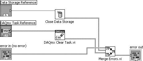

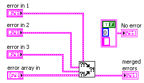
An error cluster can contain information about one, and only one, error. (This is a limitation in the data structure that carries a long legacy.) Merge Errors.vi merges several errors cluster inputs into a single error output. However, if there are errors in more than one input, it must choose which of these errors will take top priority and be passed to error out. It uses a top-to-bottom priority scheme, giving error in 1 top priority, then error in 2, and so on.
In the example shown in Figure 7.72, it is critical that the upstream error be wired to error in 1 (the top-most error input terminal) to ensure that the upstream error takes priority over any errors that occur inside our subVI.
Figure 7.72. Merge Errors.vi
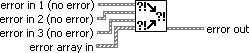
(Programming>>Dialog & User Interface palette). Merges error I/O clusters from different functions. This VI first looks for errors among error in 1, error in 2, and error in 3; then error array in and reports the first error found. If the VI finds no errors, it looks for warnings and returns the first warning found. If the VI finds no warnings, it returns no error.

Use merge errors to combine the error clusters of parallel tasks, or tasks that must each execute regardless of upstream errors.
Handling Errors in SubVIs
It is a good practice for a subVI to make a reasonable attempt to fulfill its contract (its stated job, per the software design requirements) in every way it can before passing an error up.
For example, imagine you are writing a routine that initializes an XY motion stage. (This might actually be the case, for some of our readers.) In order to find the home position (X = 0, Y = 0), the stage is moved at a low velocity toward a position sensor that outputs a digital signal of 1 (TRUE) when the stage reaches the home position. However, because there is a lot of electrical noise coming from the stage motors, the position sensor sometimes fails to report when the stage is at the home position (it sometimes jumps to 0, momentarily). This causes the initialization routine to fail at a rate of about one (1) out of twenty (20) tries, or 5% of the time. When it does fail, it always outputs the same error code. The noisy home position sensor signal has no other effect on the system, except for the occasional error during the homing operation.
Knowing what you know about the rate of failure and the type of failure, why not adapt your homing routine to retry (up to a certain number of times) before actually outputting an error message to the calling VI? This would make your code robust: fault tolerant and able to get the job done in spite of minor errors. Wouldn’t your end users be much happier if you made this change? Think of all those times they’ve started an experiment and came back to the lab an hour later expecting to find their experiment completed but, instead, they find that the system has generated that blankity-blank error while trying to home the stage… again!
OK, you agree that handling errors in subVIs is a great idea. Because the error cluster is just that, a cluster, you can use the cluster functions such as Unbundle By Name and Bundle By Name to access and modify the error data. For example, you can unbundle the error code.
Generating Errors in SubVIs
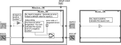
When you call a subVI or function and it generates an error, you can either try again (or perhaps try something else) or you can give up and propagate error (passing it downstream or up to the calling VI). But what happens when you want to generate a new error, perhaps because of an invalid input passed down from the calling VI? For this situation, you should use Error Cluster From Error Code.vi to generate a new error (see Figure 7.73).
Figure 7.73. Error Cluster From Error Code.vi
Error Cluster From Error Code.vi (Programming>>Dialog & User Interface palette) converts an error or warning code to an error cluster. This VI is useful when you receive a return value from a DLL call or when you return user-defined error codes.
For example, Figure 7.74 shows how we might generate an error in a subVI when an invalid argument is passed into the subVI (the TRUE case of the inner Case Structure is shown only for illustration purposes). In this example (which is located on the CD at EVERYONE/CH07/Calculate Square Root with Error.vi), we are calculating the square root of a number x. If x is negative, we will output an error (error code 1, which signifies an argument error) and default output data.
Figure 7.74. Calculate Square Root with Error.vi block diagram
Giving Up: Displaying Error Messages to the User
If error conditions cannot be handled by subVIs or in your top-level application, you can «give up» (but, please don’t accept defeat too easily) and display an error message to the user. This is the «last resort» of error handling. Figure 7.75 shows an error being passed to Simple Error Handler.vi (found on the Programming>>Dialog & User Interface palette) to display a dialog containing the error information. In this case, we passed a negative number to the subVI shown in Figure 7.74, which is an invalid input.
Figure 7.75. Calling Calculate Square Root with Error.vi as a subVI
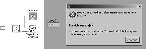
Figure 7.76. Simple Error Handler.vi
Simple Error Handler.vi (Programming>>Dialog & User Interface palette) indicates whether an error occurred. If an error occurred, this VI returns a description of the error and optionally displays a dialog box. This VI calls the General Error Handler VI and has the same basic functionality as General Error Handler but with fewer options.
Extra Tips for Error Handling
Use the following tips for successful error handling.
Use the Explain Error Dialog
When an error cluster control or indicator contains an error or warning, you can learn more about an error by selecting Explain Error from the cluster’s pop-up menu, as shown in Figure 7.77.
Figure 7.77. Selecting Explain Error from the pop-up menu of an error cluster to open the Explain Error dialog (shown in Figure 7.78)
This will display the Explain Error dialog, as shown in Figure 7.78.
Figure 7.78. Explain Error dialog, which shows a detailed error explanation
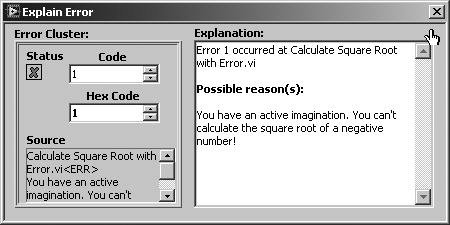
Go with the Dataflow: Use Error In and Error Out Terminals
When you add error in and error out I/O terminals to your VIs, you allow calling VIs the opportunity to chain the error cluster wire to create dataflow dependencies between subVIs. Also, you are enabling applications to perform error handling, which is a good programming practice. Even if your subVI might not ever generate an error itself, put error I/O terminals on the front panel, and put an Error Case Structure on the block diagram (as you just learned) to allow errors to propagate through the software.
Make sure to wire error in to the lower-left terminal and error out to the lower-right terminal of the VI connector panethis is a best practice.
Define Your Own Errors: User-Defined Error Codes
For large applications, you might want to explore user-defined error codes, which are specific to your application. The LabVIEW Help documentation describes the process for defining and using this feature.
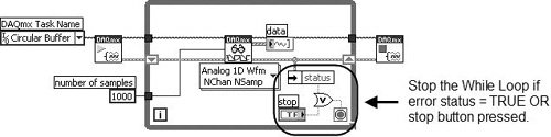
Don’t Get Stuck in a Loop: Test Error Status in Loops
It is almost always a good idea to check for errors inside of loops, so that you can exit the loop if an error occurs. Figure 7.79 shows how this is done. Note that the loop will stop if either the stop button is pressed or an error occurs.
Figure 7.79. Checking for errors in a While Loop to exit the loop when there is an error
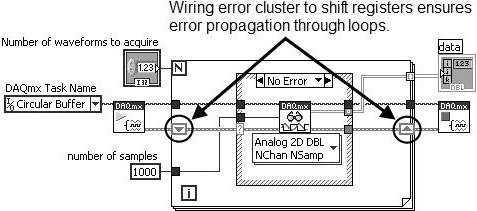
Use Shift Registers to Pass Errors Through Loops
Always use shift registers (not tunnels) for passing error clusters through the wall of a loop. This is especially important for a For Loop, as shown in Figure 7.80. Remember, if a For Loop executes zero times, data still passes from the input shift register to the output shift register. Wiring error clusters to shift registers on a For Loop ensures that errors propagate through the For Loop if it executes zero times.
Figure 7.80. Using shift registers to pass errors through loops
LabVIEW follows a dataflow model for running VIs. A block diagram node executes when it receives all required inputs. When a node executes, it produces output data and passes the data to the next node in the dataflow path. The movement of data through the nodes determines the execution order of the VIs and functions on the block diagram.
Visual Basic, C++, Java, and most other text-based programming languages follow a control flow model of program execution. In control flow, the sequential order of program elements determines the execution order of a program.
For a dataflow programming example, consider a block diagram that adds two numbers and then subtracts 50.00 from the result of the addition, as shown in Figure 1. In this case, the block diagram executes from left to right, not because the objects are placed in that order, but because the Subtract function cannot execute until the Add function finishes executing and passes the data to the Subtract function. Remember that a node executes only when data is available at all of its input terminals and supplies data to the output terminals only when the node finishes execution.
Figure 1. Dataflow Programming Example
In Figure 2, consider which code segment would execute first—the Add, Random Number, or Divide function. You cannot know because inputs to the Add and Divide functions are available at the same time, and the Random Number function has no inputs. In a situation where one code segment must execute before another, and no data dependency exists between the functions, use other programming methods, such as sequence structures or error clusters, to force the order of execution.
Figure 2. Dataflow Example for Multiple Code Segments
You transfer data among block diagram objects through wires. In figures 1 and 2, wires connect the control and indicator terminals to the Add and Subtract function. Each wire has a single data source, but you can wire it to many VIs and functions that read the data. Wires are different colors, styles, and thicknesses, depending on their data types.

A broken wire appears as a dashed black line with a red X in the middle, as shown above. Broken wires occur for a variety of reasons, such as when you try to wire two objects with incompatible data types.
Table 1 shows the most common wire types.
Table 1. Common Wire Types
In LabVIEW, you use wires to connect multiple terminals together to pass data in a VI. You must connect the wires to inputs and outputs that are compatible with the data that is transferred with the wire. For example, you cannot wire an array output to a numeric input. In addition the direction of the wires must be correct. You must connect the wires to only one input and at least one output. For example, you cannot wire two indicators together. The components that determine wiring compatibility include the data type of the control and/or the indicator and the data type of the terminal. For example, if a switch has a green border, you can wire a switch to any input with a green label on an Express VI. If a knob has an orange border, you can wire a knob to any input with an orange label. However, you cannot wire an orange knob to an input with a green label. Notice the wires are the same color as the terminal.
As you move a selected object close to other objects on the block diagram, LabVIEW draws temporary wires to show you valid connections. When you release the mouse button to place the object on the block diagram, LabVIEW automatically connects the wires. You also can automatically wire objects already on the block diagram. LabVIEW connects the terminals that best match and does not connect the terminals that do not match.
By default, automatic wiring is enabled when you select an object from the Functions palette or when you copy an object already on the block diagram by pressing the <Ctrl> key and dragging the object. Automatic wiring is disabled by default when you use the Positioning tool to move an object already on the block diagram.
You can adjust the automatic wiring settings by selecting Tools»Options and selecting Block Diagram from the Category list.
When you pass the Wiring tool over a terminal, a tip strip appears with the name of the terminal. In addition, the terminal blinks in theContext Help window and on the icon to help you verify that you are wiring to the correct terminal. To wire objects together, pass the Wiring tool over the first terminal, click, pass the cursor over the second terminal, and click again. After wiring, you can right-click the wire and select Clean Up Wire from the shortcut menu to have LabVIEW automatically choose a path for the wire. If you have broken wires to remove, press <Ctrl-B> to delete all the broken wires on the block diagram.
Included in the Section
Selecting a Tool
Shortcut Menus
Property Dialog Boxes
Front Panel Window Toolbar
Block Diagram Window Toolbar
In a graphical programming language such as LabVIEW software, the mouse is the main way to interact with the programming environment. That said, the mouse pointer must be able to accomplish many different tasks, such as selecting, wiring, highlighting text, and so on. This module examines not only the many functions that the mouse can accomplish in LabVIEW but also how to go about completing those tasks.
This module also covers a few other important ways of modifying your VIs: shortcut menus, property dialogs and the toolbar.
Selecting a Tool
You can create, modify, and debug VIs using the tools provided by LabVIEW. A tool is a special operating mode of the mouse cursor. The operating mode of the cursor corresponds to the icon of the tool selected. LabVIEW selects this tool based on the current location of the mouse.

Figure 1. Tools Palette
You can manually choose the tool you need by selecting it on the Tools palette. Select View»Tools Palette to display the Tools palette.
Automatic Tool Selector
The top item in the Tools palette is the Automatic Tool Selection button. When you select this, LabVIEW automatically chooses a tool based on the location of your cursor. You can turn off automatic tool selection by deselecting the item or by selecting another item in the palette.
If you were to compare the tools in LabVIEW to common household tools, the individual tools listed below would represent a screwdriver, knife, and corkscrew, and the automatic tool selector would be a Swiss army knife that is capable of accomplishing all tasks.

Figure 2.Individual Tools and Automatic Tool Selector
Listed below are some of the more common tools that you encounter in LabVIEW. Note that when the Automatic Tool Selection button is enabled, the mouse changes into one of the following tools to accomplish the most common tasks in LabVIEW.
Operating Tool

Use the Operating tool to change the values of a control. For example, in Figure 3 the Operating tool moves the pointer on the Horizontal Pointer Slide. When the mouse hovers over the pointer, the cursor automatically accesses the Operating tool.

Figure 3. Using the Operating Tool
The Operating tool is mostly used on the front panel window, but you also can use the Operating tool on the block diagram window to change the value of a Boolean constant.
Positioning Tool

Use the Positioning tool to select or resize objects. For example, in Figure 4 the Positioning tool selects the Number of Measurementsnumeric control. After selecting an object, you can move, copy, or delete the object. When the mouse hovers over the edge of an object, the cursor automatically accesses the Positioning tool.

Figure 4. Using the Positioning Tool to Select an Object
If the mouse hovers over a resizing node of an object, the cursor mode changes to show that you can resize the object, as shown inFigure 5. Notice that the cursor is hovering over a corner of the XY Graph at a resizing node, and the cursor mode changes to a double-sided arrow.

Figure 5. Using the Positioning Tool to Resize an Object
You can use the Positioning tool on both the front panel window and the block diagram.
Labeling Tool

Use the Labeling tool to enter text in a control, to edit text, and to create free labels. For example, in Figure 6 the Labeling tool enters text in the Number of Measurements numeric control. When the mouse hovers over the interior of the control, the cursor automatically accesses the Labeling tool. Click once to place a cursor inside the control. Then double-click to select the current text.

Figure 6. Using the Labeling Tool
When you are not in a specific area of a front panel window or block diagram window that accesses a certain mouse mode, the cursor appears as cross-hairs. If automatic tool selection is enabled, you can double-click any open space to access the Labeling tool and create a free label.
Wiring Tool

Use the Wiring tool to wire objects together on the block diagram. For example, in Figure 7, the Wiring tool wires the Number of Measurements terminal to the count terminal of the For Loop. When the mouse hovers over the exit or entry point of a terminal or over a wire, the cursor automatically accesses the Wiring tool.

Figure 7. Using the Wiring Tool
The Wiring tool works mainly with the block diagram window and when you create a connector pane on the front panel window.
Other Tools Accessed from the Palette
You can access the following additional tools on the palette:

Use the Object Shortcut Menu tool to access an object shortcut menu with the left mouse button. You also can access this menu by right-clicking any object in LabVIEW.

Use the Scrolling tool to scroll through windows without using scrollbars.

Use the Breakpoint tool to set breakpoints on VIs, functions, nodes, wires, and structures to pause execution at that location.

Use the Probe tool to create probes on wires on the block diagram. Also use the Probe tool to check intermediate values in a VI that produces questionable or unexpected results.

Use the Coloring tool to color an object. The Coloring tool also displays the current foreground and background color settings.

Use the Get Color tool to copy colors for pasting with the Coloring tool.
Shortcut Menus
All LabVIEW objects have associated shortcut menus, also known as context menus, pop-up menus, and right-click menus. As you create a VI, use the shortcut menu items to change the appearance or behavior of front panel and block diagram objects. To access the shortcut menu, right-click the object.

Figure 8. Shortcut Menu for a Meter
Property Dialog Boxes
Objects in the front panel window also have property dialog boxes that you can use to change the look or behavior of the objects. Right-click an object and select Properties from the shortcut menu to access the property dialog box for an object. Figure 9 shows the property dialog box for the meter shown in Figure 8. The options available on the property dialog box for an object are similar to the options available on the shortcut menu for that object.

Figure 9. Property Dialog Box for a Meter
You can select multiple objects on the front panel or the block diagram and edit any properties the objects share. To select multiple objects, use the Positioning tool to drag a selection rectangle around all of the objects you want to edit or hold down the <Shift> key while clicking each object. Right-click an object from the selection and select Properties from the shortcut menu to display theProperties dialog box. The Properties dialog box only displays tabs and properties that the objects you select share. Select similar objects to display more tabs and properties. If you select objects that do not share any common properties, the Properties dialog box does not display any tabs or properties.
Front Panel Window Toolbar
Each window has a toolbar associated with it. Use the front panel window toolbar buttons to run and edit the VI.
The following toolbar appears on the front panel window.


Click the Run button to run a VI. LabVIEW compiles the VI, if necessary. You can run a VI if the Run button appears as a solid white arrow, as shown at left. The solid white arrow also indicates you can use the VI as a subVI if you create a connector pane for the VI.

While the VI runs, the Run button appears as shown if the VI is a top-level VI, meaning it has no callers and therefore is not a subVI.

If the VI that is running is a subVI, the Run button appearance changes as shown.

The Run button appears broken when the VI you are creating or editing contains errors. If the Run button still appears broken after you finish wiring the block diagram, the VI is broken and cannot run. Click this button to display the Error list window, which lists all errors and warnings.

Click the Run Continuously button to run the VI until you abort or pause execution. You also can click the button again to disable continuous running.

While the VI runs, the Abort Execution button appears. Click this button to stop the VI immediately if there is no other way to stop the VI. If more than one running top-level VI uses the VI, the button is dimmed.
Caution: The Abort Execution button stops the VI immediately, before the VI finishes the current iteration. Aborting a VI that uses external resources, such as external hardware, might leave the resources in an unknown state by not resetting or releasing them properly. Design VIs with a stop button to avoid this problem.

Click the Pause button to pause a running VI. When you click the Pause button, LabVIEW highlights on the block diagram the location where you paused execution, and the Pause button appears red. Click the Pause button again to continue running the VI.

Select the Text Settings pull-down menu to change the font settings for the selected portions of the VI, including size, style, and color.

Select the Align Objects pull-down menu to align objects along axes, including vertical, top edge, left, and so on.

Select the Distribute Objects pull-down menu to space objects evenly, including gaps, compression, and so on.

Select the Resize Objects pull-down menu to resize multiple front panel objects to the same size.

Select the Reorder pull-down menu when you have objects that overlap each other and you want to define which one is in front or back of another. Select one of the objects with the Positioning tool and then select from Move Forward, Move Backward, Move To Front, and Move To Back.

The LabVIEW search can locate information in the LabVIEW Help, in the Controls and Functions palettes, and from NI support, community support, downloads, and product information sections on ni.com. You can configure which categories you want LabVIEW to search by selecting Tools»Options and selecting Search from the Category list.

Select the Show Context Help Window button to toggle the display of the Context Help window.

Enter Text appears to remind you that a new value is available to replace an old value. The Enter Text button disappears when you click it, press the <Enter> key, or click the front panel or block diagram workspace.
Block Diagram Window Toolbar


Click the Clean Up Diagram button to automatically reroute all existing wires and rearrange objects on the block diagram to generate a cleaner layout. To configure the clean up options, select Tools»Options to display the Options dialog box and select Block Diagram: Cleanup from the Category list.
The other buttons unique to the block diagram toolbar are primarily used for troubleshooting and are covered in the Debugging Tools document
Debugging Tools in LabVIEW
Included in the Section
Fixing Broken VIs
Finding Causes for Broken VIs
Common Causes of Broken VIs
Fixing Incorrect Behavior
Block Diagram Toolbar
Probe Tool
LabVIEW software contains powerful debugging tools to help you identify problem areas in your code so you can make the appropriate changes. You may encounter two general types of software bugs: those that prevent the program from running and those that generate bad results or incorrect behavior. This module teaches you how to identify and troubleshoot both types of errors.
If LabVIEW cannot run your VI, it informs you by changing the run arrow to a broken icon, and the Error List window lists the specific reasons why the VI is broken. The second type of bug is typically harder to track down, but LabVIEW has several tools you can use to watch your code as it executes, which makes the process much easier.
Fixing Broken VIs
If a VI does not run, it is a broken, or nonexecutable, VI. The Run button appears broken when the VI you are creating or editing contains errors.
Generally, this means that a required input is not wired, or a wire is broken. Press the broken Run button to access the Error List window. The Error List window lists each error and describes the problem. You can double-click an error to go directly to the error.
Finding Causes for Broken VIs
Warnings do not prevent you from running a VI. They are designed to help you avoid potential problems in VIs. Errors, however, can break a VI. You must resolve any errors before you can run the VI.
Click the broken Run button or select View»Error List to find out why a VI is broken. The Error List window lists all the errors. The Items with Errors section lists the files that have errors. If two or more items have the same name, this section shows the specific application instance for each item. The Errors and Warnings section lists the errors and warnings for the VI you select in the Items with Errors section. The Details section describes the errors and, in some cases, recommends how to correct the errors. Click the Help button to display a topic in the LabVIEW Help that describes the error in detail and includes step-by-step instructions for correcting the error.
Click the Show Error button or double-click the error description to highlight the area on the block diagram or front panel that contains the error.

Figure 1. Example of the Error List Dialog Box
Common Causes of Broken VIs
The following list contains common reasons why a VI is broken while you edit it:
The block diagram contains a broken wire because of a mismatch of data types or a loose, unconnected end. Refer to the Correcting Broken Wires topic of the LabVIEW Help for information about correcting broken wires.
A required block diagram terminal is unwired. Refer to the Using Wires to Link Block Diagram Objects topic of the LabVIEW Help for information about setting required inputs and outputs.
A subVI is broken or you edited its connector pane after you placed its icon on the block diagram of the VI.
Fixing Incorrect Behavior
If your VI runs but produces incorrect results then you have a functional error in your code. LabVIEW has several tools to help you analyze where your VI is not behaving as expected.
Block Diagram Toolbar
When you run a VI, buttons appear on the block diagram toolbar that you can use to debug the VI. The following toolbar appears on the block diagram.

Click the Highlight Execution button to display an animation of the block diagram execution when you run the VI. Notice the flow of data through the block diagram. Click the button again to disable execution highlighting.
Execution highlighting shows the movement of data on the block diagram from one node to another using bubbles that move along the wires. Use execution highlighting with single-stepping to see how data values move from node to node through a VI.
Note: Execution highlighting greatly reduces the speed at which the VI runs.

Figure 2. Example of Execution Highlighting in Use

Click the Retain Wire Values button to save the wire values at each point in the flow of execution so that when you place a probe on the wire you can immediately retain the most recent value of the data that passed through the wire. You must successfully run the VI at least once before you can retain the wire values.


Click the Step Into button to open a node and pause. When you click the Step Into button again, it executes the first action and pauses at the next action of the subVI or structure. You also can press the <Ctrl> and down arrow keys. Single-stepping through a VI steps through the VI node by node. Each node blinks to denote when it is ready to execute.

Click the Step Over button to execute a node and pause at the next node. You also can press the <Ctrl> and right arrow keys. By stepping over the node, you execute the node without single-stepping through the node.

Click the Step Out button to finish executing the current node and pause. When the VI finishes executing, the Step Out button is dimmed. You also can press the <Ctrl> and up arrow keys. By stepping out of a node, you complete single-stepping through the node and navigate to the next node.

The Warning button appears if a VI includes a warning and you placed a checkmark in the Show Warnings checkbox in the Error List window. A warning indicates a potential problem with the block diagram, but it does not stop the VI from running.
Probe Tool
Use the Probe tool to check intermediate values on a wire as a VI runs.
Use the Probe tool if you have a complicated block diagram with a series of operations, any one of which might return incorrect data. Use the Probe tool with execution highlighting, single-stepping, and breakpoints to determine if and where data is incorrect. If data is available, the probe immediately updates and displays the data in the Probe Watch Window during execution highlighting, single-stepping, or when you pause at a breakpoint. When execution pauses at a node because of single-stepping or a breakpoint, you also can probe the wire that just executed to see the value that flowed through that wire.
Data Structures in LabVIEW
Included in the Section
String Data Type
Numeric Data type
Boolean Data Type
Dynamic Data Type
Arrays
Clusters
Enums
String Data Type

A string is a sequence of displayable or nondisplayable ASCII characters. Strings provide a platform-independent format for information and data. Some of the more common applications of strings include the following:
Creating simple text messages.
Controlling instruments by sending text commands to the instrument and returning data values in the form of either ASCII or binary strings, which you then convert to numeric values.
Storing numeric data to disk. To store numeric data in an ASCII file, you must first convert numeric data to strings before writing the data to a disk file.
Instructing or prompting the user with dialog boxes.
On the front panel, strings appear as tables, text entry boxes, and labels. LabVIEW includes built-in VIs and functions you can use to manipulate strings, including formatting strings, parsing strings, and other editing. LabVIEW represents string data with the color pink.
Find more information on string data
Numeric Data Type


LabVIEW represents numeric data as floating-point numbers, fixed-point numbers, integers, unsigned integers, and complex numbers. Double and Single precision as well as Complex numeric data is represented with the color orange in LabVIEW. All Integer numeric data is represented with the color blue.
Note: The difference among the numeric data types is the number of bits they use to store data and the data values they represent.
Certain data types also provide extended configuration options. For example, you can associate physical units of measure with floating-point data, including complex numbers, and you can configure the encoding and range for fixed-point data.
Find more information on numeric data
View a table of numeric data types
Boolean Data Type

LabVIEW stores Boolean data as 8-bit values. You can use a Boolean in LabVIEW to represent a 0 or 1, or a TRUE or FALSE. If the 8-bit value is zero, the Boolean value is FALSE. Any nonzero value represents TRUE. Common applications for Boolean data include representing digital data and serving as a front panel control that acts as a switch that has a mechanical action often used to control an execution structure such as a Case structure. A Boolean control is typically used as the conditional statement to exit a While Loop. In LabVIEW, the color green represents Boolean data.
Find more information about Boolean control of mechanical actions
Dynamic Data Type

Most Express VIs accept and/or return the dynamic data type, which appears as a dark blue terminal.
Using the Convert to Dynamic Data and Convert from Dynamic Data VIs, you can convert floating-point numeric or Boolean data of the following data types:
1D array of waveforms
1D array of scalars
1D array of scalars—most recent value
1D array of scalars—single channel
2D array of scalars—columns are channels
2D array of scalars—rows are channels
Single scalar
Single waveform
Wire the dynamic data type to an indicator that can best present the data. Indicators include a graph, chart, or numeric, or Boolean indicator. However, because dynamic data undergoes an automatic conversion to match the indicator to which it is wired, Express VIs can slow down the block diagram execution speed.
The dynamic data type is for use with Express VIs. Most other VIs and functions that are shipped with LabVIEW do not accept this data type. To use a built-in VI or function to analyze or process the data the dynamic data type includes, you must convert the dynamic data type.
Find more information on dynamic data
Arrays
Sometimes it is beneficial to group related data. Use arrays and clusters to group related data in LabVIEW. Arrays combine data points of the same data type into one data structure, and clusters combine data points of multiple data types into one data structure.
An array consists of elements and dimensions. Elements are the data points that make up the array. A dimension is the length, height, or depth of an array. An array can have one or more dimensions and as many as (231)—1 elements per dimension, memory permitting.
You can build arrays of numeric, Boolean, path, string, waveform, and cluster data types. Consider using arrays when you work with a collection of similar data points and when you perform repetitive computations. Arrays are ideal for storing data you collect from waveforms or data generated in loops, where each iteration of a loop produces one element of the array.
Note: Array indexes in LabVIEW are zero-based. The index of the first element in the array, regardless of its dimension, is zero.
Array elements are ordered. An array uses an index so you can readily access any particular element. The index is zero-based, which means it is in the range of 0 to n-1, where n is the number of elements in the array. For example, n-12 represents the 12 months of the year, so the index ranges from 0 to 11. March is the third month, so it has an index of 2.
Figure 1 shows an example of an array of numerics. The first element shown in the array (3.00) is at index 1, and the second element (1.00) is at index 2. The element at index 0 is not shown in this image because element 1 is selected in the index display. The element selected in the index display always refers to the element shown in the upper left corner of the element display.

(1) Index Display | (2) Element Display
Figure 1. Array Control of Numerics
Creating Array Controls and Indicators
Create an array control or indicator on the front panel by adding an array shell to the front panel, as shown in Figure 2, and dragging a data object or element, such as a numeric or string control, into the array shell.

Figure 2. Placing a Numeric Control in an Array Shell
If you attempt to drag an invalid control or indicator into the array shell, you are unable to place the control or indicator in the array shell.
You must insert an object in the array shell before you use the array on the block diagram. Otherwise, the array terminal appears black with an empty bracket and has no data type associated with it.
Two-Dimensional Arrays
The previous examples use 1D arrays. A 2D array stores elements in a grid. It requires a column index and a row index to locate an element, both of which are zero-based. Figure 3 shows an 8 column by 8 row 2D array, which contains 8 × 8 = 64 elements.

Figure 3. 2D Array
To add a multidimensional array to the front panel, right-click the index display and select Add Dimension from the shortcut menu. You also can resize the index display until you have as many dimensions as you want.
Initializing Arrays
You can initialize an array or leave it uninitialized. When an array is initialized, you defined the number of elements in each dimension and the contents of each element. An uninitialized array contains a fixed number of dimensions but no elements. Figure 4 shows an uninitialized 2D array control. Notice that the elements are all dimmed. This indicates that the array is uninitialized.

Figure 4. 2D Uninitialized Array
In a 2D array, after you initialize an element, any uninitialized element in that column and in previous columns are initialized and populated with the default value for the data type. In Figure 5, a value of 4 was entered in column 2, of the 0-based array. The previous elements in column 0, 1, and 2 are initialized to 0, which is the default value for the numeric data type.
Figure 5. An Initialized 2D Array With Nine Elements
Creating Array Constants
To create an array constant on the block diagram, select an array constant on the Functions palette, place the array shell on the block diagram, and place a string constant, numeric constant, Boolean constant, or cluster constant in the array shell. You can use an array constant to store constant data or as a basis for comparison with another array.
Auto-Indexing Array Inputs

If you wire an array to or from a For Loop or While Loop, you can link each iteration of the loop to an element in that array by enabling auto-indexing. The tunnel image changes from a solid square to the image to indicate auto-indexing. Right-click the tunnel and select Enable Indexing or Disable Indexing from the shortcut menu to toggle the state of the tunnel.
Array Inputs
If you enable auto-indexing on an array wired to a For Loop input terminal, LabVIEW sets the count terminal to the array size so you do not need to wire the count terminal. Because you can use For Loops to process arrays one element at a time, LabVIEW enables auto-indexing by default for every array you wire to a For Loop. You can disable auto-indexing if you do not need to process arrays one element at a time.
In Figure 6, the For Loop executes a number of times equal to the number of elements in the array. Normally, if the count terminal of the For Loop is not wired, the run arrow is broken. However, in this case the run arrow is not broken.

Figure 6. Array Used to Set For Loop Count
If you enable auto-indexing for more than one tunnel or if you wire the count terminal, the actual number of iterations becomes the smaller of the choices. For example, if two auto-indexed arrays enter the loop, with 10 and 20 elements respectively, and you wire a value of 15 to the count terminal, the loop still executes only 10 times, indexing all elements of the first array but only the first 10 elements of the second array.
Array Outputs
When you auto-index an array output tunnel, the output array receives a new element from every iteration of the loop. Therefore, auto-indexed output arrays are always equal in size to the number of iterations.
The wire from the output tunnel to the array indicator becomes thicker as it changes to an array at the loop border, and the output tunnel contains square brackets representing an array.

Figure 7. Auto-Indexed Output
Right-click the tunnel at the loop border and select Enable Indexing or Disable Indexing from the shortcut menu to enable or disable auto-indexing. Auto-indexing for While Loops is disabled by default.
For example, disable auto-indexing if you need only the last value passed out of the tunnel.
Creating Two-Dimensional Arrays
You can use two For Loops, nested one inside the other, to create a 2D array. The outer For Loop creates the row elements, and the inner For Loop creates the column elements.

Figure 8. Creating a 2D Array
Clusters
Clusters group data elements of mixed types. An example of a cluster is the LabVIEW error cluster, which combines a Boolean value, a numeric value, and a string. A cluster is similar to a record or a struct in text-based programming languages.
Bundling several data elements into clusters eliminates wire clutter on the block diagram and reduces the number of connector pane terminals that subVIs need. The connector pane has, at most, 28 terminals. If your front panel contains more than 28 controls and indicators that you want to pass to another VI, group some of them into a cluster and assign the cluster to a terminal on the connector pane.
Most clusters on the block diagram have a pink wire pattern and data type terminal. Error clusters have a dark yellow wire pattern and data type terminal. Clusters of numeric values, sometimes referred to as points, have a brown wire pattern and data type terminal. You can wire brown numeric clusters to Numeric functions, such as Add or Square Root, to perform the same operation simultaneously on all elements of the cluster.
Order of Cluster Elements
Although cluster and array elements are both ordered, you must unbundle all cluster elements at once using the Unbundle function. You can use the Unbundle By Name function to unbundle cluster elements by name. If you use the Unbundle by Name function, each cluster element must have a label. Clusters also differ from arrays in that they are a fixed size. Like an array, a cluster is either a control or an indicator. A cluster cannot contain a mixture of controls and indicators.
Creating Cluster Controls and Indicators
Create a cluster control or indicator on the front panel by adding a cluster shell to the front panel, as shown in the following front panel, and dragging a data object or element, which can be a numeric, Boolean, string, path, refnum, array, or cluster control or indicator, into the cluster shell.
Resize the cluster shell by dragging the cursor while you place the cluster shell.

Figure 9. Creation of a Cluster Control
Figure 10 is an example of a cluster containing three controls: a string, a Boolean switch, and a numeric.

Figure 10. Cluster Control Example
Creating Cluster Constants
To create a cluster constant on the block diagram, select a cluster constant on the Functions palette, place the cluster shell on the block diagram, and place a string constant, numeric constant, Boolean constant, or cluster constant in the cluster shell. You can use a cluster constant to store constant data or as a basis for comparison with another cluster.
If you have a cluster control or indicator on the front panel window and you want to create a cluster constant containing the same elements on the block diagram, you can either drag that cluster from the front panel window to the block diagram or right-click the cluster on the front panel window and select Create»Constant from the shortcut menu.
Using Cluster Functions
Use the Cluster functions to create and manipulate clusters. For example, you can perform tasks similar to the following:
Extract individual data elements from a cluster.
Add individual data elements to a cluster.
Break a cluster out into its individual data elements.
Use the Bundle function to assemble a cluster, use the Bundle function and Bundle by Name function to modify a cluster, and use the Unbundle function and the Unbundle by Name function to disassemble clusters.
You also can place the Bundle, Bundle by Name, Unbundle, and Unbundle by Name functions on the block diagram by right-clicking a cluster terminal on the block diagram and selecting the Cluster, Class & Variant Palette from the shortcut menu. The Bundle and Unbundle functions automatically contain the correct number of terminals. The Bundle by Name and Unbundle by Name functions appear with the first element in the cluster. Use the Positioning tool to resize the Bundle by Name and Unbundle by Name functions to show the other elements of the cluster.
Assembling Clusters
Use the Bundle function to assemble a cluster from individual elements or to change the values of individual elements in an existing cluster without having to specify new values for all elements. Use the Positioning tool to resize the function or right-click an element input and select Add Input from the shortcut menu.

Figure 11. Assembling a Cluster on the Block Diagram
Modifying a Cluster
If you wire the cluster input, you can wire only the elements you want to change. For example, the Input Cluster shown in Figure 12contains three controls.

Figure 12. Bundle Used to Modify a Cluster
If you know the cluster order, you can use the Bundle function to change the Command value by wiring the elements shown in Figure 12.
You can also use the Bundle by Name function to replace or access labeled elements of an existing cluster. The Bundle by Name function works like the Bundle function, but instead of referencing cluster elements by their cluster order, it references them by their owned labels. You can access only elements with owned labels. The number of inputs does not need to match the number of elements in an output cluster.
Use the Operating tool to click an input terminal and select an element from the pull-down menu. You also can right-click the input and select the element from the Select Item shortcut menu.
In Figure 13, you can use the Bundle by Name function to update the values of Command and Function with the values of New Command and New Function.

Figure 13. Bundle by Name Used to Modify a Cluster
Use the Bundle by Name function for data structures that might change during development. If you add a new element to the cluster or modify its order, you do not need to rewire the Bundle by Name function because the names are still valid.
Disassembling Clusters
Use the Unbundle function to split a cluster into its individual elements.
Use the Unbundle by Name function to return the cluster elements whose names you specify. The number of output terminals does not depend on the number of elements in the input cluster.
Use the Operating tool to click an output terminal and select an element from the pull-down menu. You also can right-click the output terminal and select the element from the Select Item shortcut menu.
For example, if you use the Unbundle function with the cluster in Figure 14, it has four output terminals that correspond to the four controls in the cluster. You must know the cluster order so you can associate the correct Boolean terminal of the unbundled cluster with the corresponding switch in the cluster. In this example, the elements are ordered from top to bottom starting with element 0. If you use the Unbundle by Name function, you can have an arbitrary number of output terminals and access individual elements by name in any order.

Figure 14. Unbundle and Unbundle by Name
Enums
An enum (enumerated control, constant or indicator) is a combination of data types. An enum represents a pair of values, a string and a numeric, where the enum can be one of a list of values. For example, if you created an enum type called Month, the possible value pairs for a Month variable are January-0, February-1, and so on through December-11. Figure 15 shows an example of these data pairs in the Properties dialog box for an enumerated control. This is directly accessed by right-clicking the enum control and selectingEdit Items.

Figure 15. Properties for the Month Enumerated Control
Enums are useful because it is easier to manipulate numbers on the block diagram than strings. Figure 16 shows the Month enumerated control, the selection of a data pair in the enumerated control, and the corresponding block diagram terminal.

(1) Front Panel Control | (2) Selecting an Item | (3) Block Diagram Terminal
Figure 16. Month Enumerated Control
Probe Tool
Use the Probe tool to check intermediate values on a wire as a VI runs.
Use the Probe tool if you have a complicated block diagram with a series of operations, any one of which might return incorrect data. Use the Probe tool with execution highlighting, single-stepping, and breakpoints to determine if and where data is incorrect. If data is available, the probe immediately updates and displays the data in the Probe Watch Window during execution highlighting, single-stepping, or when you pause at a breakpoint. When execution pauses at a node because of single-stepping or a breakpoint, you also can probe the wire that just executed to see the value that flowed through that wire.
Execution Structures in LabVIEW
Included in the Section
Loops
Case Structures
Other Structures
Execution structures contain sections of graphical code and control how and when the code inside is run. The most common execution structures are While Loops, For Loops and Case structures which you can use to run the same section of code multiple times or to execute a different section of code based on some condition.
Loops
Video: Creating Loops in LabVIEW
While Loops
Similar to a Do Loop or a Repeat-Until Loop in text-based programming languages, a While Loop, shown in Figure 1, executes the code it contains until a condition occurs.

(1) LabVIEW While Loop | (2) Flowchart | (3) Pseudo Code
Figure 1 shows a While Loop in LabVIEW, a flowchart equivalent of the While Loop functionality,
and a pseudo code example of the functionality of the While Loop.
The While Loop is located on the Structures palette. Select the While Loop from the palette and then use the cursor to drag a selection rectangle around the section of the block diagram you want to repeat. When you release the mouse button, a While Loop boundary encloses the section you selected.
Add block diagram objects to the While Loop by dragging and dropping them inside the While Loop.
The While Loop executes the code it contains until the conditional terminal, an input terminal, receives a specific Boolean value.
You also can perform basic error handling using the conditional terminal of a While Loop. When you wire an error cluster to the conditional terminal, only the True or False value of the status parameter of the error cluster passes to the terminal. Also, the Stop if True and Continue if True shortcut menu items change to Stop if Error and Continue while Error.

The iteration terminal is an output terminal that contains the number of completed iterations.
The iteration count for the While Loop always starts at zero.
Note: The While Loop always executes at least once.
Infinite Loops
Infinite loops are a common programming mistake that involves a loop that never stops.
If the conditional terminal is Stop if True, you place the terminal of a Boolean control outside a While Loop. If the control is FALSE when the loop starts, you cause an infinite loop.

Figure 2. Boolean Control Outside the While Loop
Changing the value of the control does not stop the infinite loop because the value is read only once, and that happens before the loop starts. To use a control to stop a While Loop, you should place the control terminal inside the loop. To stop an infinite loop, you must abort the VI by clicking the Abort Execution button on the toolbar.
In Figure 3 the While Loop executes until the Random Number function output is greater than or equal to 10.00 and the Enable control is True. The And function returns True only if both inputs are True. Otherwise, it returns False.
In Figure 3, there is an infinite loop since the random function never generates a value equal to or greater than 10.0 0.

Figure 3. Infinite Loop
Structure Tunnels
Tunnels feed data into and out of structures. The tunnel appears as a solid block on the border of the While Loop. The block is the color of the data type wired to the tunnel. Data passes out of a loop after the loop terminates. When a tunnel passes data into a loop, the loop executes only after the data arrives at the tunnel.
In Figure 4, the iteration terminal is connected to a tunnel. The value in the tunnel does not get passed to the Iterations indicator until the While Loop finishes executing.

Figure 4. While Loop Tunnel
Only the last value of the iteration terminal displays in the Iterations indicator.
For Loops
Video: Using For Loops in LabVIEW
A For Loop executes a subdiagram a set number of times. Figure 5 shows a For Loop in LabVIEW, a flowchart equivalent of the For Loop functionality, and a pseudo code example of the functionality of the For Loop.

(1) LabVIEW For Loop | (2) Flowchart | (3) Pseudo Code
Figure 5. For Loop
The For Loop is on the Structures palette. You also can place a While Loop on the block diagram, right-click the border of the While Loop, and select Replace with For Loop from the shortcut menu to change a While Loop to a For Loop.

The count terminal is an input terminal whose value indicates how many times to repeat the subdiagram.
The iteration terminal is an output terminal that contains the number of completed iterations.
The iteration count for the For Loop always starts at zero.
The For Loop differs from the While Loop in that the For Loop executes a set number of times. A While Loop stops executing only if the value at the conditional terminal exists.
The For Loop in Figure 6 generates a random number every second for 100 seconds and displays the random numbers in a numeric indicator.

Figure 6. For Loop Example
Adding Timing to Loops
When a loop finishes executing an iteration, it immediately begins executing the next iteration, unless it reaches a stop condition. Most often, you need to control the iteration frequency or timing. For example, if you are acquiring data, and you want to acquire the data once every 10 seconds, you need a way to time the loop iterations so they occur once every 10 seconds. Even if you do not need the execution to occur at a certain frequency, you need to provide the processor with time to complete other tasks, such as responding to the user interface.
Wait Function
Place a Wait function inside a loop to allow a VI to sleep for a set amount of time. This allows your processor to address other tasks during the wait time. Wait functions use the millisecond clock of the operating system.

The Wait (ms) function waits until the millisecond counter counts to an amount equal to the input you specify. This function guarantees that the loop execution rate is at least the amount of the input you specify.
Case Structures
Video: Using Case Structures in LabVIEW

A Case structure has two or more subdiagrams, or cases.
Only one subdiagram is visible at a time, and the structure executes only one case at a time. An input value determines which subdiagram executes. The Case structure is similar to switch statements or if…then…else statements in text-based programming languages.

The case selector label at the top of the Case structure contains the name of the selector value that corresponds to the case in the center and decrement and increment arrows on each side.
Click the decrement and increment arrows to scroll through the available cases. You also can click the down arrow next to the case name and select a case from the pull-down menu.

Wire an input value, or selector, to the selector terminal to determine which case executes.
You must wire an integer, Boolean value, string, or enumerated type value to the selector terminal. You can position the selector terminal anywhere on the left border of the Case structure. If the data type of the selector terminal is Boolean, the structure has a True case and a False case. If the selector terminal is an integer, string, or enumerated type value, the structure can have any number of cases.
Note: By default, string values you wire to the selector terminal are case sensitive. To allow case-insensitive matches, wire a string value to the selector terminal, right-click the border of the Case structure, and select Case Insensitive Match from the shortcut menu.
If you do not specify a default case for the Case structure to handle out-of-range values, you must explicitly list every possible input value. For example, if the selector is an integer and you specify cases for 1, 2, and 3, you must specify a default case to execute if the input value is 4 or any other unspecified integer value.
Note: You cannot specify a default case if you wire a Boolean control to the selector. If you right-click the case selector label, Make This The Default Case does not appear in the shortcut menu. Make the Boolean control TRUE or FALSE to determine which case to execute.
Right-click the Case structure border to add, duplicate, remove, or rearrange cases, and to select a default case.
Selecting a Case
Figure 7 shows a VI that uses a Case structure to execute different code depending on whether a user selects °C or °F for temperature units. The top block diagram shows the True case in the foreground. In the middle block diagram, the False case is selected. To select a case, enter the value in the case selector identifier or use the Labeling tool to edit the values. After you select another case, that case displays on the block diagram, as shown in the bottom block diagram of Figure 7.

Figure 7. Changing the Case View of a Case Structure
If you enter a selector value that is not the same type as the object wired to the selector terminal, the value appears red. This indicates that the VI will not run until you delete or edit the value. Also, because of the possible round-off error inherent in floating-point arithmetic, you cannot use floating-point numbers as case selector values. If you wire a floating-point value to the case, LabVIEW rounds the value to the nearest integer. If you type a floating-point value in the case selector label, the value appears red to indicate that you must delete or edit the value before the structure can execute.
Input and Output Tunnels
You can create multiple input and output tunnels for a Case structure. Inputs are available to all cases, but cases do not need to use each input. However, you must define an output tunnel for each case.
Consider the following example: a Case structure on the block diagram has an output tunnel, but in at least one of the cases, there is no output value wired to the tunnel. If you run this case, LabVIEW does not know what value to return for the output. LabVIEW indicates this error by leaving the center of the tunnel white. The unwired case might not be the case that is currently visible on the block diagram.
To correct this error, display the case(s) that contain(s) the unwired output tunnel and wire an output to the tunnel. You also can right-click the output tunnel and select Use Default If Unwired from the shortcut menu to use the default value for the tunnel data type for all unwired tunnels. When the output is wired in all cases, the output tunnel is a solid color.
Avoid using the Use Default If Unwired option. Using this option does not document the block diagram well, and can confuse other programmers using your code. The Use Default If Unwired option also makes debugging code difficult. If you use this option, be aware that the default value used is the default value for the data type that is wired to the tunnel. For example, if the tunnel is a Boolean data type, the default value is FALSE.
| Data Type | Default Value |
|---|---|
| Numeric | 0 |
| Boolean | FALSE |
| String | empty (“”) |
Table 1. Data Type Default Values
Other Structures
LabVIEW has other, more advanced types of execution structures such as Event structures (used to handle interrupt-driven tasks like UI interaction) and Sequence structures (used to force execution order), which are out of the scope of this introductory material. To learn more about these structures, refer to the appropriate LabVIEW Help topic.
Passing Data Between Loop Iterations in LabVIEW
Included in the Section
Shift Registers
Initializing Shift Registers
Stacked Shift Registers
When programming with loops, you often must access data from previous iterations of the loop in LabVIEW. For example, if you are acquiring one piece of data in each iteration of a loop and must average every five pieces of data, you must retain the data from previous iterations of the loop.
Shift Registers

Use shift registers when you want to pass values from previous iterations through the loop to the next iteration. A shift register appears as a pair of terminals directly opposite each other on the vertical sides of the loop border.
The terminal on the right side of the loop contains an up arrow and stores data on the completion of an iteration. LabVIEW transfers the data connected to the right side of the register to the next iteration. After the loop executes, the terminal on the right side of the loop returns the last value stored in the shift register.
Create a shift register by right-clicking the left or right border of a loop and selecting Add Shift Register from the shortcut menu.
A shift register transfers any data type and automatically changes to the data type of the first object wired to the shift register. The data you wire to the terminals of each shift register must be the same type.
You can add more than one shift register to a loop. If you have multiple operations that use previous iteration values within your loop, use multiple shift registers to store the data values from those different processes in the structure, as shown in Figure 1.

Figure 1. Using Multiple Shift Registers
Initializing Shift Registers
Initializing a shift register resets the value the shift register passes to the first iteration of the loop when the VI runs. Initialize a shift register by wiring a control or constant to the shift register terminal on the left side of the loop, as shown in Figure 2.

Figure 2. Initialized Shift Register
In Figure 2, the For Loop executes five times, incrementing the value the shift register carries by one each time. After five iterations of the For Loop, the shift register passes the final value, 5, to the indicator and the VI quits. Each time you run the VI, the shift register begins with a value of 0. If you do not initialize the shift register, the loop uses the value written to the shift register when the loop last executed or, if the loop has never executed, the default value for the data type. Use an uninitialized shift register to preserve state information between subsequent executions of a VI.

Figure 3. Uninitialized Shift Register
In Figure 3, the For Loop executes five times, incrementing the value the shift register carries by one each time. The first time you run the VI, the shift register begins with a value of 0, which is the default value for a 32-bit integer. After five iterations of the For Loop, the shift register passes the final value, 5, to the indicator, and the VI quits. The next time you run the VI, the shift register begins with a value of 5, which was the last value from the previous execution. After five iterations of the For Loop, the shift register passes the final value, 10, to the indicator. If you run the VI again, the shift register begins with a value of 10, and so on. Uninitialized shift registers retain the value of the previous iteration until you close the VI.
Stacked Shift Registers
With stacked shift registers, you can access data from previous loop iterations. Stacked shift registers remember values from multiple previous iterations and carry those values to the next iterations. To create a stacked shift register, right-click the left terminal and select Add Element from the shortcut menu.
Stacked shift registers can occur only on the left side of the loop because the right terminal transfers the data generated from only the current iteration to the next iteration.

Figure 4. Using Stacked Shift Registers
If you add another element to the left terminal in the previous block diagram, values from the last two iterations carry over to the next iteration, with the most recent iteration value stored in the top shift register. The bottom terminal stores the data passed to it from the previous iteration.
Handling Errors in LabVIEW
Included in the Section
Automatic Error Handling
Manual Error Handling
Error Clusters
Explain Error
Using While Loops for Error Handling
No matter how confident you are in the VI you create, you cannot predict every problem a user can encounter. Without a mechanism to check for errors, you know only that the VI does not work properly. Error checking tells you why and where errors occur.
Automatic Error Handling
Each error has a numeric code and a corresponding error message.
By default, LabVIEW automatically handles any error when a VI runs by suspending execution, highlighting the subVI or function where the error occurred, and displaying an error dialog box.
To disable automatic error handling for the current VI, select File»VI Properties and select Execution from the Category pull-down menu. To disable automatic error handling for any new, blank VIs you create, select Tools»Options and select Block Diagram from theCategory list. To disable automatic error handling for a subVI or function within a VI, wire its error out parameter to the error inparameter of another subVI or function or to an error out indicator.
Manual Error Handling
You can choose other error handling methods. For example, if an I/O VI on the block diagram times out, you might not want the entire application to stop and display an error dialog box. You also might want the VI to retry for a certain period of time. In LabVIEW, you can make these error handling decisions on the block diagram of the VI.
Use the LabVIEW error handling VIs and functions on the Dialog & User Interface palette and the error in and error out parameters of most VIs and functions to manage errors. For example, if LabVIEW encounters an error, you can display the error message in different kinds of dialog boxes. Use error handling with the debugging tools to find and manage errors.
When you perform any kind of input and output (I/O), consider the possibility that errors might occur. Almost all I/O functions return error information. Include error checking in VIs, especially for I/O operations (file, serial, instrumentation, DAQ, and communication), and provide a mechanism to handle errors appropriately.
Use the LabVIEW error handling VIs, functions, and parameters to manage errors. For example, if LabVIEW encounters an error, you can display the error message in a dialog box. Or you can fix the error programmatically and then erase the error by wiring the error-out output of the subVI or function to the error in input of the Clear Errors VI. Use error handling with the debugging tools to find and manage errors.
Error Clusters
Error handling in LabVIEW follows the dataflow model. Just as data values flow through a VI, so can error information. Wire the error information from the beginning of the VI to the end. Include an error handler VI, such as the Simple Error Handler VI, at the end of the VI to determine if the VI ran without errors. Use the error in and error out clusters in each VI you use or build to pass the error information through the VI.
As the VI runs, LabVIEW tests for errors at each execution node. If LabVIEW does not find any errors, the node executes normally. If LabVIEW detects an error, the node passes the error to the next node without executing that part of the code. The next node does the same thing, and so on. At the end of the execution flow, LabVIEW reports the error.
Use the error cluster controls and indicators to create error inputs and outputs in subVIs.
The error in and error out clusters include the following components of information:
status is a Boolean value that reports TRUE if an error occurred.
code is a 32-bit signed integer that identifies the error numerically. A nonzero error code coupled with a status of FALSE signals a warning rather than an error.
source is a string that identifies where the error occurred.
Explain Error
When an error occurs, right-click within the cluster border and select Explain Error from the shortcut menu to open the Explain Error dialog box. The Explain Error dialog box contains information about the error. The shortcut menu includes an Explain Warning option if the VI contains warnings but no errors.
You also can access the Explain Error dialog box from the Help»Explain Error menu.
Using While Loops for Error Handling
You can wire an error cluster to the conditional terminal of a While Loop or to a For Loop with a conditional terminal to stop the iteration of the loop. If you wire the error cluster to the conditional terminal, only the TRUE or FALSE value of the status parameter of the error cluster passes to the terminal. If an error occurs, the loop stops. In a For Loop with a conditional terminal, you also must wire a value to the count terminal or auto-index an input array to set a maximum number of iterations. The For Loop executes until an error occurs or until the number of set iterations completes.
If you wire an error cluster to the conditional terminal, the shortcut menu items Stop if True and Continue if True change to Stop on Error and Continue while Error.
In Figure 1, the error cluster and a stop button are used together to determine when to stop the loop. This is the recommended method for stopping most loops since the loop stops when you ask it to, or when something goes wrong (and produces an error), whichever comes first.

Figure 1. Stopping a While Loop
Finding Examples for LabVIEW
Included in the Section
NI Example Finder
ni.com/examples
For most LabVIEW projects, especially when you are new to LabVIEW, it is beneficial to start from a working example and modify the code to fit your needs.
NI Example Finder
Video: Using Example Finder
Use the NI Example Finder to browse or search examples installed on your computer. These examples demonstrate how to use LabVIEW to perform a wide variety of test, measurement, control, and design tasks. Select Help»Find Examples or click the Find Examples link in the Examples section of the Getting Started window to launch the NI Example Finder.
Examples can show you how to use specific VIs or functions. You can right-click a VI or function on the block diagram or on a pinned palette and select Examples from the shortcut menu to display a help topic with links to examples for that VI or function. You can modify an example VI to fit an application, or you can copy and paste from one or more examples into a VI that you create.

Figure 1. Example Finder
Hardware drivers such as NI-DAQmx or LabVIEW Plug and Play instrument drivers install examples into the Hardware Input and Output folder, which are good starting points when working with hardware devices.
ni.com/examples
In addition to the examples that install with LabVIEW, thousands more are available online at ni.com/examples. Online examples include both community and NI contributed code that you can download and use as a starting point for your own applications.
Using NI LabVIEW In-Product Help
Included in the Section
Context Help Window
LabVIEW Help
Use the Context Help window and the LabVIEW Help to create and edit VIs.
Context Help Window

The Context Help window displays basic information about LabVIEW objects when you move the cursor over each object. To toggle display of the Context Help window select Help»Show Context Help, press the <Ctrl-H> keys, or click the Show Context Help Window button on the toolbar.
When you move the cursor over front panel and block diagram objects, the Context Help window displays the icon for subVIs, functions, constants, controls, and indicators, with wires attached to each terminal. When you move the cursor over dialog box options, the Context Help window displays descriptions of those options.

Figure 1. Context Help Window

Click the Show Optional Terminals and Full Path button located on the lower left corner of the Context Help window to display the optional terminals of a connector pane and to display the full path to a VI. Optional terminals are shown by wire stubs, informing you that other connections exist. The detailed mode displays all terminals, as shown in Figure 2. The labels of required terminals appear bold, recommended terminals appear as plain text, and optional terminals appear dimmed.

Figure 2. Detailed Context Help Window

Click the Lock Context Help button to lock the current contents of the Context Help window. When the contents are locked, moving the cursor over another object does not change the contents of the window. To unlock the window, click the button again. You also can access this option from the Help menu.

If a corresponding LabVIEW Help topic exists for an object the Context Help window describes, a blue Detailed help link appears in the Context Help window. Also, the Detailed help button is enabled. Click the link or the button to display the LabVIEW Help for more information about the object.
LabVIEW Help
The LabVIEW Help is the best source of detailed information about specific features and functions in LabVIEW. The LabVIEW Help offers conceptual topics, how-to topics with step-by-step instructions for using LabVIEW features, and complete reference information.
You can access the LabVIEW Help by clicking the blue Detailed help link or button in the Context Help window or by selecting Help»LabVIEW Help. You also can right-click an object and select Help from the shortcut menu.
After you install a LabVIEW add-on such as a toolkit, module, or driver, the documentation for that add-on appears in the LabVIEW Help or appears in a separate help system you access by selecting Help»Add-On Help, where Add-On Help is the name of the separate help system for the add-on.
Online LabVIEW Help Resources
Included in the Section
ni.com/support
KnowledgeBase
Forums
If you are unable to find the help you need in the LabVIEW Help, you can explore more resources online to answer your LabVIEW questions.
ni.com/support
The main online support portal for LabVIEW is ni.com/support. This page contains links to the latest manuals, updates, and other support resources for all of your NI software and hardware.
KnowledgeBase
The KnowledgeBase houses thousands of answers to frequently asked questions, troubleshooting tips for common errors and other support documentation written by NI applications engineers.
Forums
The NI Discussion Forums are another source of help for both beginners and advanced LabVIEW users. Search the forums for similar questions or post one of your own and learn from the collective wisdom of LabVIEW users worldwide. NI applications engineers also monitor the forums to ensure that all questions are answered.
Additional Help for LabVIEW
Included in the Section
NI Support Engineers
NI Training
NI Alliance Partners
If you still have LabVIEW questions that have not been answered by any of the self-service help outlets, you can contact an NI expert for personal assistance.
NI Support Engineers
If you have a valid support contract, you can contact NI application engineers directly via phone or e-mail. Your purchase of LabVIEW includes one year of Standard Service Program (SSP) membership, which entitles you to technical support as well as software updates.
Create a service request
View more information on SSP
If you do not have a support contract, you can still receive assistance from NI through the NI Discussion Forums.
NI Training
If you are looking for more assistance to get started with LabVIEW, NI training helps you build the skills to more efficiently develop powerful, maintainable applications. NI provides several training options including classroom, self-paced, online, or on-site training at your facility.
Explore your NI training options
NI Alliance Partners
Whether you are looking for assistance in completing a small integration project, require in-depth expertise in building a large multifaceted system or solution, or want to find a turnkey solution, Alliance Partners have the resources and know-how to provide what you need in every region and every industry.
Learn more about Alliance Partners
NEXT —-> TO LEARN