Ниже приведен перевод некоторых ошибок, возникающих при запуске расчета FDS, а также рекомендации по устранению этих ошибок.
Список далеко не полный. Если вам встретилась ошибка, которой нет в списке, пишите сюда, будем пополнять список.
ERROR: Problem with SURF number 1
ERROR: Problem with REAC number 1
ERROR: Problem with OBST number 1
ERROR: Problem with VENT number 1
ERROR: Problem with HOLE number 1
ERROR: Problem with DEVC number 1
и другие аналогичные ошибки. (SURF — поверхность, REAC — реакция, OBST — препятствие, VENT — вентиляционное отверстие, HOLE — отверстие, DEVC — датчик)
Указанный объект имеет неверные или противоречивые параметры. Номер означает порядковый номер объекта в текстовом виде.
Обратите внимание! Первыми считаются данные, находящиеся в поле «Дополнительные записи».
ERROR: OPEN, MIRROR, OR PERIODIC VENT 1 must be an exterior boundary
Вентиляционное отверстие с поверхностью OPEN, MIRROR или PERIODIC должно располагаться на внешней границе сетки.
Т.е. такое вентиляционное отверстие не может располагаться на препятствии.
ERROR: VENT 1 must be attached to a solid obstruction
Вентиляционное отверстие (VENT) должно быть присоединено к твердой поверхности (препятствию или границе сетки).
1. Проверьте, что координаты вентиляционного отверстия и препятствия (или границы сетки) совпадают, т.е. VENT действительно лежит на твердой поверхности.
2. Если границы объекта не лежат точно на границах ячеек сетки, FDS сдвигает границы к ближайшим ячейкам. При этом может получиться так, что вентиляционное отверстие было сдвинуто к одной границе, а препятствие к другой. Поэтому желательно задавать координаты точно по сетке.
3. Проверьте, что препятствие, к которому присоединен VENT, имеет толщину хотя бы в одну ячейку сетки.
Проверить, как выглядят объекты, выровненные по сетке, можно, нажав на верхней панели инструментов кнопку «Предварительный просмотр блоков FDS».
ERROR: Memory allocation failed in the routine INIT
Ошибка означает, что не хватает оперативной памяти для запуска расчета.
Вероятно, в модели слишком много ячеек. Попробуйте уменьшить расчетный объем либо увеличить размеры ячеек сетки.
ERROR: Must specify fuel chemistry using C and/or H when using simple chemistry
В топливе с простой химией должны быть обязательно заданы C и/или H.
ERROR: Fuel FORMULA for SIMPLE_CHEMISTRY can only contain C,H,O, and N
В топливе с простой химией могут использоваться только элементы C,H,O и N
ERROR: SURF fire indicates burning, but there is no REAC line
Судя по поверхности, в модели присутствует горение (т.е. задана поверхность «горелка» или «многослойная» с соответствующими свойствами), но не задано ни одной реакции.
Проверьте, что реакция задана и сделана активной.
ERROR: SPEC AIR, sub species 1 not found
ERROR: SPEC PRODUCTS, sub species 1 not found
Такие ошибки возникают, если не задан какой-либо газ, который используется в реакциях.
Проверьте, что вы полностью скопировали данные из файла «реакции с хлором». Проверьте, что вы задали установили галочку «Всегда включать в записи FDS» для газов CARBON DIOXIDE (CO2), CARBON MONOXIDE (CO), OXYGEN (O2) и HYDROGEN CHLORIDE (HCl) (меню «Модель» — «Редактировать газы» для каждого газа на вкладке «Дополнительно»).
Последний раз редактировалось FireCat 19 фев 2015, 15:49, всего редактировалось 1 раз.
Содержание
- FireCat
- Список ошибок при запуске расчета FDS
- Список ошибок при запуске расчета FDS
- Что означает Power Saving Mode на мониторе и как его исправить?
- Причины появления сообщения Power Saving Mode
- Как избавиться от Power Saving Mode?
- Случай 1. Power Saving Mode при включении ПК
- Случай 2. Power Saving Mode после замены блока питания, видеокарты и т д
- Случай 3. Power Saving Mode во время работы ПК, при запуске игр и приложений
- Случай 4. Power Saving Mode сразу после старта Windows
- Если вышеописанные решения не помогли…
- Power supply surges detected during the previous power on что делать?
- В чём же причины данной проблемы?
- Как исправить ошибку Power supply surges detected during the previous power on
- Заключение
FireCat
Форум пользователей программного комплекса FireCat
Список ошибок при запуске расчета FDS
Модератор: Ilya
Список ошибок при запуске расчета FDS
Сообщение FireCat » 15 янв 2015, 17:20
Ниже приведен перевод некоторых ошибок, возникающих при запуске расчета FDS, а также рекомендации по устранению этих ошибок.
Список далеко не полный. Если вам встретилась ошибка, которой нет в списке, пишите сюда, будем пополнять список.
ERROR: Problem with SURF number 1
ERROR: Problem with REAC number 1
ERROR: Problem with OBST number 1
ERROR: Problem with VENT number 1
ERROR: Problem with HOLE number 1
ERROR: Problem with DEVC number 1
и другие аналогичные ошибки. (SURF — поверхность, REAC — реакция, OBST — препятствие, VENT — вентиляционное отверстие, HOLE — отверстие, DEVC — датчик)
Указанный объект имеет неверные или противоречивые параметры. Номер означает порядковый номер объекта в текстовом виде.
Обратите внимание! Первыми считаются данные, находящиеся в поле «Дополнительные записи».
ERROR: OPEN, MIRROR, OR PERIODIC VENT 1 must be an exterior boundary
Вентиляционное отверстие с поверхностью OPEN, MIRROR или PERIODIC должно располагаться на внешней границе сетки.
Т.е. такое вентиляционное отверстие не может располагаться на препятствии.
ERROR: VENT 1 must be attached to a solid obstruction
Вентиляционное отверстие (VENT) должно быть присоединено к твердой поверхности (препятствию или границе сетки).
1. Проверьте, что координаты вентиляционного отверстия и препятствия (или границы сетки) совпадают, т.е. VENT действительно лежит на твердой поверхности.
2. Если границы объекта не лежат точно на границах ячеек сетки, FDS сдвигает границы к ближайшим ячейкам. При этом может получиться так, что вентиляционное отверстие было сдвинуто к одной границе, а препятствие к другой. Поэтому желательно задавать координаты точно по сетке.
3. Проверьте, что препятствие, к которому присоединен VENT, имеет толщину хотя бы в одну ячейку сетки.
Проверить, как выглядят объекты, выровненные по сетке, можно, нажав на верхней панели инструментов кнопку «Предварительный просмотр блоков FDS».
ERROR: Memory allocation failed in the routine INIT
Ошибка означает, что не хватает оперативной памяти для запуска расчета.
Вероятно, в модели слишком много ячеек. Попробуйте уменьшить расчетный объем либо увеличить размеры ячеек сетки.
ERROR: Must specify fuel chemistry using C and/or H when using simple chemistry
В топливе с простой химией должны быть обязательно заданы C и/или H.
ERROR: Fuel FORMULA for SIMPLE_CHEMISTRY can only contain C,H,O, and N
В топливе с простой химией могут использоваться только элементы C,H,O и N
ERROR: SURF fire indicates burning, but there is no REAC line
Судя по поверхности, в модели присутствует горение (т.е. задана поверхность «горелка» или «многослойная» с соответствующими свойствами), но не задано ни одной реакции.
Проверьте, что реакция задана и сделана активной.
ERROR: SPEC AIR, sub species 1 not found
ERROR: SPEC PRODUCTS, sub species 1 not found
Такие ошибки возникают, если не задан какой-либо газ, который используется в реакциях.
Проверьте, что вы полностью скопировали данные из файла «реакции с хлором». Проверьте, что вы задали установили галочку «Всегда включать в записи FDS» для газов CARBON DIOXIDE (CO2), CARBON MONOXIDE (CO), OXYGEN (O2) и HYDROGEN CHLORIDE (HCl) (меню «Модель» — «Редактировать газы» для каждого газа на вкладке «Дополнительно»).
Источник
Что означает Power Saving Mode на мониторе и как его исправить?

Во время запуска операционной системы пользователь первым видит логотип материнской платы или производителя монитора, далее – заставку самой операционной системы. Однако бывают случаи, когда при включении монитора юзер видит надпись Power Saving Mode, которую можно перевести как «Режим энергосбережения». Этот режим может активироваться в период неиспользования рабочего ПК, то есть, когда включается ждущий режим и монитор отключается для экономии энергии. Однако надпись Power Saving Mode на мониторе может появляться и из-за неисправности. Поэтому, предлагаем разобраться, почему появляется надпись Power Saving Mode на мониторах и как от неё избавиться.
Причины появления сообщения Power Saving Mode
Активация энергосберегающего режима и появление надписи Power Saving Mode на мониторе возможна как в норме, так и при неисправности. Как в первом, так и во втором случае причин тому может быть несколько:
- Переход компьютера в спящий режим. Компьютер при этом продолжает работать.
- Видеовход монитора подключен к гнезду видеокарты, которая неактивна. Пример тому может быть следующим. На ПК установлено две видеокарты: дискретная и встроенное видеоядро в процессор. При подключении к дискретной видеокарте, графика процессора, как правило, отключается автоматически. Однако, если произошел сбой, то пользователь будет видеть сообщение Power Saving Mode на черном экране монитора.
- Кабель, с помощью которого ПК подключён к монитору, может быть поврежден или отсутствовать контакт с разъемом. Нужно проверить качество подключения.
- Повреждение разъемов видеокарты и монитора также могут сигнализировать об отсутствии видеосигнала. Нужно проверить также слот подключение видеокарты на материнской плате.
- Если вы используете для подключения монитора адаптер-переходник, то через его неисправность или несовместимость также может появляться сообщение Power Saving Mode.
- Неверное разрешение дисплея видеокартой может спровоцировать отсутствие видеосигнала.
- Перегрев и неисправность видеокарты.
Если вы попытались вывести монитор из спящего режима, но это не удалось, или надпись Power Saving Mode появилась при загрузке Windows, то действия по решению неполадки будут следующие.
Как избавиться от Power Saving Mode?
Поскольку надпись Power Saving Mode на мониторе может появляться в различных ситуациях, то и методы её решения будут завесить от каждого конкретного случая.
Случай 1. Power Saving Mode при включении ПК
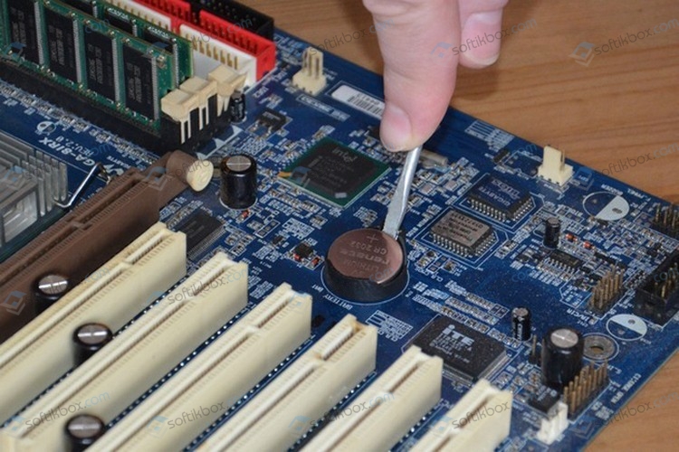
Если при включении компьютера вы наблюдаете надпись Power Saving Mode, которая не сменяется логотипом материнской платы и последующей загрузкой Windows, то советуем выключить его, отключить от электросети. Далее нужно на 15-20 секунд зажать кнопку питания, чтобы снять остатки заряда с конденсаторов и других элементов системной сборки. Если это был временный сбой, то последующий запуск ПК должен оказаться успешным и на мониторе появится изображение. Если же такая ситуация наблюдается часто, то, вероятнее всего, неполадка кроется в источнике питания. Нужно проверить блок питания, конденсаторы на материнской плате, кабели питания от монитора и самого ПК.
Случай 2. Power Saving Mode после замены блока питания, видеокарты и т д
Если после замены блока питания и видеокарты при запуске ПК на мониторе появляется надпись Power Saving Mode, то нужно сбросить настройки BIOSа аппаратным методом. Нужно либо воспользоваться перемычками на материнской плате или на несколько минут вытянуть батарейку на материнской плате.
Случай 3. Power Saving Mode во время работы ПК, при запуске игр и приложений
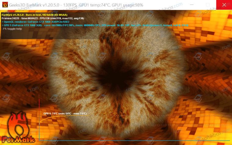
Если Power Saving Mode на мониторе появляется после запуска игры или приложения, то причина может крыться в перегреве видеокарты. Рекомендуем почистить ПК от пыли, позаботиться о дополнительном охлаждении видеокарты и процессора. Для проверки устройств на перегрев рекомендуем использовать программу AIDA64 (для определения температуры процессора со встроенной графикой) и FurMark.
Случай 4. Power Saving Mode сразу после старта Windows
Неправильное разрешение экрана может вызвать надпись на черном экране. Если после старта Windows на вашем мониторе появилась запись Power Saving Mode, стоит выполнить следующее:
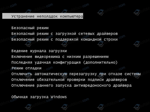
- Загружаем ПК в безопасном режиме. Для этого во время старта ПК нужно нажать F8 и выбрать нужный пункт.
- Переходим по адресу «Панель управления», «Оформление и персонализация», «Экран», «Разрешение экрана» (если у вас Windows 10, то нужно открыть «Параметры», «Система», «Дисплей»).
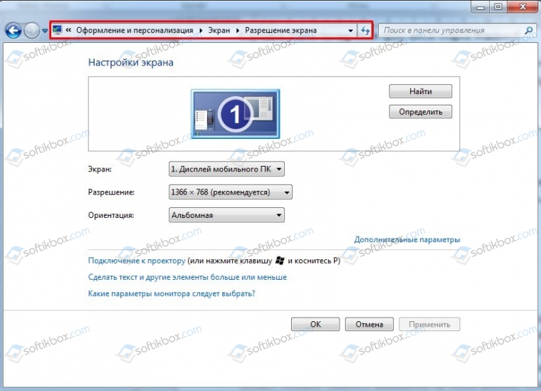
- Нужно задать минимальное разрешение и перезагрузить ПК. После последующей перезагрузки в нормальном режиме ошибка должна исчезнуть.
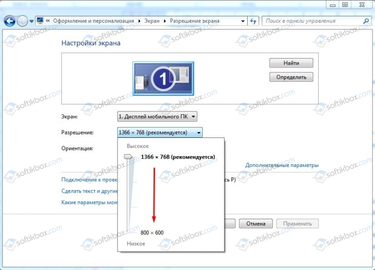
- Теперь можно путем экспериментов определить оптимальное значение для монитора, чтобы надпись не появлялась.
Если вышеописанные решения не помогли…
Если избавиться от надписи на экране монитора вышеуказанными способами не удалось, то нужно приступить к экспериментам.
- Заменяем видеокабель на аналогичный, только новый. Если изображение появилось, то виновник – кабель. Если нет, то возможна поломка в интерфейсе. Пробуем подключить монитор с помощью другого разъема. Если и со вторым разъемом ситуация повторяется, то причина может крыться в видеокарте.
- Диагностируем видеокарту. Изначально можно установить видеоускоритель в другой слот PCI на материнской плате. Нужно, чтобы видеокарте хватало питания. Если и во втором слоте видеокарта не дала изображения, то видеокарта либо не рабочая, либо несовместима с материнской платой.
- Если видеокарта работает, но периодически появляется такой черный экран, то проблема может крыться в прошивке BIOS. Можно попытаться обновить BIOS, надеясь, что производитель включил в новую версию поддержку вашего устройства. Однако, если материнская плата или ноутбук на гарантии, то за обновлением прошивки материнской платы стоит обратиться в сервисный центр.
Если же вообще ничего из вышеперечисленного не помогает, стоит подключить монитор к другому ПК. Если он не работает, то причина в самом устройстве и его нужно продиагностировать специалистом либо полностью заменить.
Источник
Power supply surges detected during the previous power on что делать?
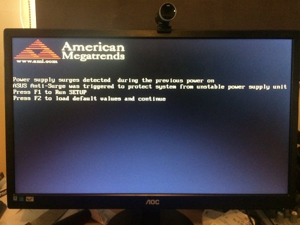
Пользователи компьютеров на базе материнских плат «Asus» могут столкнуться с внезапной перезагрузкой их системы. После перезагрузки на экране высвечивается сообщение «Power supply surges detected during the previous power on. ASUS Anti-surge was triggered to protect system from unstable power supply unit.». Нажав на F2 пользователь может продолжить загрузку своей системы, но через какое-то время компьютер вновь внезапно перезагружается, и уже упомянутая надпись вновь появляется на экране. В этой статье я расскажу, что это за проблема, каковы её причины, и как её исправить на вашем ПК.
В чём же причины данной проблемы?
В переводе с английского языка данное сообщение выглядит как «Зафиксирован скачок напряжения во время предыдущей работы. Инструмент «ASUS Anti-surge» был активирован для защиты системы от нестабильного блока питания».
То есть, встроенный в материнскую плату инструмент «ASUS Anti-surge» зафиксировал угрожающий скачок напряжения от блока питания, и для обеспечения безопасной работы компьютера выполнил отключение (перезагрузку) ПК.
Напомню читателю, что инструмент «ASUS Anti-surge» является специальной разработкой компании ASUS, направленной на защиту системы от перегрузок питания. Управляется данный инструмент через БИОС, где его можно легко включить/отключить.
Какие причины могли привести к упомянутому скачку напряжения? Я бы выделил следующее:
- Нестабильный (слабый по мощности, исчерпавший свой ресурс) блок питания компьютера;
- Скачки напряжения в сети (в том числе из-за действия подключенных к данной сети электроприборов);
- Нестабильно работающий сетевой фильтр;
- Недостаточно плотное соединение кабелей от блока питания к материнской плате.

Функция «ASUS Anti-surge» защищает материнскую плату ПК от скачков напряжения
Как исправить ошибку Power supply surges detected during the previous power on
Итак, если у вас произошла asus anti-surge перезагрузка, тогда, прежде всего, рекомендую понаблюдать, будет ли повторяться данная проблема. Если внезапные выключения компьютера продолжаются, и вы на экране видите сообщения о действии «ASUS Anti-surge», а сверху надпись American Megatrends, тогда рекомендую выполнить следующее:
- Проверьте плотность соединения кабелей от БП к материнской плате компьютера;
- Запускайте игровые программы на более слабых настройках, выбор максимальных может привести к активации AAS и отключению системы;
- Смените блок питания. Рекомендую приобрести более мощный БП от зарекомендовавшего себя производителя. В большинстве случаев в появлении дисфункции «ASUS Anti-surge» виноват именно БП, выдающий нестабильное напряжение;

Если вы осознаёте все риски, и решили отключить функцию asus anti-surge protect, тогда перейдите в «БИОС» — «Advanced Mode» — «Monitor» — «Anti Surge Support», и установите данный параметр в значение «Disabled» (отключен).
Заключение
Чтобы решить проблему «Power supply surges detected during the previous power on» рекомендую, прежде всего, проверить состояние блока питания вашего ПК, при необходимости сменив его на более мощный (особенно в случае, если вы используете вашу систему для компьютерных игр). В качестве паллиатива можно посоветовать отключение функции AAS в «БИОС», но при этом учтите, что вы действуете на свой страх и риск, и будет лучше оставить AAS активной, нежели потом сожалеть о выходе системы из строя.
Источник

when I use renderonce in the script the image is saved with correct file name, however with renderdoubleonce I get an automatic file name. smokeview version 6.7.5

As of 6.7.9, FDS only displays «FDS» in the title bar of the Command window when run on Windows, so when running multiple cases in parallel, a case can only be identified by scrolling to the beginning in its command window.
To enable case identification at a quick glance, Windows’ Batch script supports the «TITLE» command to define a custom title for a particular window.
Therefore, I suggest adding TITLE FDS (%casename%) to line 85 or so (above %ECHO% mpiexec -localonly [...]) in binfds_local.bat. This sets the window title just before calling mpiexec.exe and will display the path to the case in the Command window title bar.

Hello, I probably miss some understanding of how FDS works with pressure if not in regards to the mass and temperature.
I created a simplified example (attached) from a case. Here we have two compartments, 3 zones (0-outer, 1-apartment/fire, 2-staircase). There is no leakage between Zone 1 and Zone 2 until a heat detector opens a duct dumper under the zone, and the pressure zones are sealed from each other (no error at the beginning of the simulation). The smoke / mass does not go between the zones until the duct has been activated. Yet, Zone 2 (staircase) copies the pressure measuring (in the HRR file) in Zone 1 (apartment/fire) from the very beginning of the simulation (without mass transport) and once the window in Zone 2 (staircase) opens, the pressure in Zone 1 (apartment/fire) drops as well (even without an opened duct).

How does Zone 2 get increasing pressure (perfectly corresponding to Zone 1) when there is no mass or some extensive heat transport to it? What is the excessive mass in Zone 2 and where does it come from?

The staircase window on the upper floor opens at the pressure peak, then the pressure drops. The pressure drops also in Zone 1 (apartment/fire); even though, there is no mass transport between them. The smoke is still kept in Zone 1, nothing leaks to Zone 2.
Mass transport through the duct indeed activates when the damp on the duct is triggered (much later in the simulation).
I have tried ULMAT and it still leaks, so I doubt it is a leak through thin obstructions (and there are none), and even if there was some, the pressure still should not be identical.
PRESSURE_ZONE_LEAK.fds.txt

It seems that if a surface has AREA_MULTIPLIER>1 , the MLR output in _hrr.csv file is too high by a factor of AREA_MULTIPLIER, i.e. the area multiplier gets applied twice. This pertains to ads version 6.7.9, but appears with the latest source code also.
The following version of the box_burn_away1 demonstrates this issue. Applying AREA_MULTIPLIER =2 to the SURF_LINE increases the MLR_METHANE output by a factor of 4.
&HEAD CHID=’box_burn_away1_area_multiplier’, TITLE=’Test BURN_AWAY feature’ /
The FOAM box is evaporated away by the high thermal radiation
from HOT surfaces. The mass of the box is 0.4^3 m3 * 20 kg/m3 = 1.28 kg.
This should be compared to the final value of fuel density volume integral,
computed by the first DEVC.
&MESH IJK=10,10,10 XB=-0.3,0.7,-0.4,0.6,0.0,1.0, MULT_ID='mesh' /
&MULT ID='mesh', DX=1.0, DY=1.0, I_UPPER=1, J_UPPER=1 /

&TIME T_END=30. DT = 0.01/

&SPEC ID='METHANE' /

&MATL ID                   = 'FOAM'
      HEAT_OF_REACTION     = 800.
      CONDUCTIVITY         = 0.2
      SPECIFIC_HEAT        = 1.0
      DENSITY              = 20.
      NU_SPEC              = 1.
      SPEC_ID              = 'METHANE'
      REFERENCE_TEMPERATURE= 200. /

&SURF ID                   = 'FOAM SLAB'
      COLOR                = 'TOMATO 3'
      MATL_ID              = 'FOAM'
      THICKNESS            = 0.1
      BURN_AWAY            = .TRUE.
      BACKING              = 'EXPOSED'
      AREA_MULTIPLIER=2/

&OBST XB=0.30,0.70,0.30,0.70,0.30,0.70, SURF_ID='FOAM SLAB', BULK_DENSITY=20. /

&SURF ID='HOT', TMP_FRONT=1100., COLOR='RED' /

&VENT PBX=-0.3, SURF_ID='HOT' /
&VENT PBX= 1.7, SURF_ID='HOT' /
&VENT PBY=-0.4, SURF_ID='HOT' /
&VENT PBY= 1.6, SURF_ID='HOT' /
&VENT PBZ= 0.0, SURF_ID='HOT' /
&VENT PBZ= 1.0, SURF_ID='HOT' /

&BNDF QUANTITY='WALL TEMPERATURE' /
&BNDF QUANTITY='MASS FLUX', SPEC_ID='METHANE' /

&SLCF PBZ=0.5, QUANTITY='TEMPERATURE', CELL_CENTERED=T /
&SLCF PBZ=0.5, QUANTITY='DENSITY', CELL_CENTERED=T /
&SLCF PBZ=0.5, QUANTITY='MASS FRACTION', SPEC_ID='METHANE', CELL_CENTERED=T /

&DEVC XB=-0.3,1.7,-0.4,1.6,0,1, QUANTITY='DENSITY', SPEC_ID='METHANE', STATISTICS='VOLUME INTEGRAL', ID='Mass fuel' /
&TAIL /
The issue seems to be that AREA_ADJUST is applied twice. The offending lines in dump.f90 read.
! Determine mass loss rate of tracked gas species from solid wall cells
WALL_LOOP2: DO IW=1,N_EXTERNAL_WALL_CELLS+N_INTERNAL_WALL_CELLS
   WC => WALL(IW)
   IF (WC%BOUNDARY_TYPE/=SOLID_BOUNDARY) CYCLE WALL_LOOP2
   BC => BOUNDARY_COORD(WC%BC_INDEX)
   ONE_D => BOUNDARY_ONE_D(WC%OD_INDEX)
   AREA_F = ONE_D%AREA
   IF (TWO_D)       AREA_F = AREA_F/DY(BC%JJG)
   IF (CYLINDRICAL) AREA_F = AREA_F*2._EB*PI
   DO N=1,N_TRACKED_SPECIES
      M_DOT(N,NM) = M_DOT(N,NM) + ONE_D%M_DOT_G_PP_ADJUST(N)*AREA_F*ONE_D%AREA_ADJUST
   ENDDO
ENDDO WALL_LOOP2

This issue started as a Discussion Group post
I’m trying now to simulate a ;pmg tunnel, and it keeps crashing. I tried :
TUNNEL_PRECONDITIONNER=.T.
MAX_PRESSURE_ITERATIONS=100
VELOCITY_TOLERANCE=0.001
Everytime it is the same : Warnings about minimum density, and a few steps later numerical instability occurs.
I know I could create some small holes, but I know that my simulation will take forever with it…
Any other suggestions?
Tunnel.txt

Discussed in #11421
Originally posted by saemibang February 6, 2023
I’m trying to simulate a sprinkler pattern.
I put the same input file using ‘TABLE_DATA’ in fds version 6.7.5 and version 6.7.9, but the result was different.
Is there a big difference in droplets between the two versions?
Especially, » &PROP QUANTITY=’NUMBER CONCENTRATION’ » results

In the User Guide, section 13.1 «Time-Dependent Functions», it is defined:
The parameters TAU_Q, TAU_T, and TAU_V indicate that the heat release rate (HRRPUA); surface temperature (TMP_FRONT); and/or normal velocity (VEL, VOLUME_FLOW), or MASS_FLUX_TOTAL are to ramp up to their prescribed values in TAU seconds and remain
there.
However, the $Q_0 cdot tanh(frac{t}{tau})$ will be $0.76159 cdot Q_0$ when $t=tau$. I verified this also when inspecting the MLR_FUEL of a SURF where HRRPUA is applied. Since the $tanh$ function asymptotically approaches 1, I believe it should use a larger value, maybe $Q_0 cdot tanh(frac{3cdot t}{tau})$. Can you see if this make sense?
Thank you.

Jason,
Maybe I’m having a brain freeze, but I don’t understand why molar or mass stoic coefficients should change if we change ambient temperature. Play with TMPA in this example and look at the .out file. Maybe this is just an issue with what is put in the .out file, but it makes me nervous.
&HEAD CHID='test' /
&MESH IJK=5,5,5, XB=0,1,0,1,0,1/
&TIME T_END=0.001/
&MISC TMPA=200/ <= set to 20 and things look normal
&REAC FUEL='METHANE' /
&TAIL/
We have a case in which we are trying to simulate the burning of vehicle components.
With FDS 6.7.9-933 (and the standard 6.7.9 release), the ULMAT solver and a single mesh of approx. 1.1 million cells, the case crashes after 800 seconds with a ULMAT_H_MATRIX_LUDCMP PARDISO Num Factor: The following ERROR was detected: -2 error message.
According to the Intel PARDISO user guide (page 12), error code «-2» means not enough memory.
We have restarted the case from a restart file before the crash and noticed that RAM usage for FDS was around 6.4 GB. Our workstation has 64 GB of RAM and a 64 bit OS, so there is more than enough available memory for FDS.
Further investigation determined that Intel’s MKL library, of which PARDISO is a part, has two available modes of operation, namely in-core (IC) and out-of-core (OCC) for the construction and handling of the pressure solver matrix.
FDS uses the default mode, which is IC and, as far as we can tell, limited to a maximum of 2000 MB per core.
We assume that the increasing number of non-zero values in the matrix due to burn-away push the memory usage of the case beyond this limit, leading to a crash.
The PARDISO configuration within pres.f90 (line 3818 ff) of the FDS source code sets all flags to zero (unless those specifically altered). This also affects the corresponding IC/OCC control flag (iparm(60) according to the MKL reference manual), which is therefore locked to IC, limiting memory usage.
With IPARM(60) = 1, to our interpretation, it would be possible to switch between the (faster) IC and (slower) OCC mode depending on the values of the MKL_PARDISO_OOC_MAX_CORE_SIZE and MKL_PARDISO_OOC_MAX_SWAP_SIZE environment variables. The latter may potentially solve the memory issue with large cases and ULMAT.
Is there a chance to set IPARM(60) = 1 by default in future FDS releases and/or increase the default maximum memory for IC mode (if possible)?
Looks like the end time got changed on these. Also plot on lower right looks weird, can’t distinguish the exact from model result.

I am running UL_NFPRF_P-5.fds and the .err file is growing to hundreds of millions of lines, each one like these:
WARNING Delta TMP_G. Mesh: 1 Particle Tag: 2218406
WARNING TMP_G_N < TMP_D_N. Mesh: 1 Particle: 1
WARNING Delta TMP_G. Mesh: 1 Particle Tag: 2218406
WARNING TMP_G_N < TMP_D_N. Mesh: 1 Particle: 1
WARNING Delta TMP_G. Mesh: 1 Particle Tag: 2218406
WARNING TMP_G_N < TMP_D_N. Mesh: 1 Particle: 1
WARNING Delta TMP_G. Mesh: 1 Particle Tag: 2218406
It appears to be the same particle in some endless loop. There are 5 cases like this; the other four ran OK (I think) with an earlier version (FDS6.7.9-1300-gbeeb4d8). The latest case is running with FDS6.7.9-1381-g34dcb26. I’m going to dig deeper, but have you done anything lately with particles?

This is a modified version of the char_oxidation verification cases. A single particle of CHAR is exposed to a heat flux.
In the ‘lumped’ case, the char oxidation follows the shortcut of consuming AIR and producing PRODUCTS (and ASH). In the ‘tracked’ case, CHAR is converted to CARBON DIOXIDE and ASH, while consuming OXYGEN, with both gas species tracked directly.
The mass consumption and generation all seem consistent, but the temperature of the particle during the peak of the reaction is very different. I’ve tried using the ‘tracked’ approach but mimicking the ‘lumped’ approach (so some WATER VAPOR is produced instead of all CARBON DIOXIDE), but the result is still very different to the ‘lumped’ approach.

char_oxidation_lumped.fds.txt
char_oxidation_tracked.fds.txt
In radi.f90, around line 4169, there is an IF block
                     IF (CC_IBM) THEN
                        IF (CCVAR(I,J,K,CC_CGSC) == CC_SOLID) CYCLE SLICE_LOOP
                        AFX_AUX  = 0._EB; AFY_AUX  = 0._EB; AFZ_AUX  = 0._EB
Move this block outside of the IPROP loop and use CELL_ILW to hold the upstream value of IL.
I wanted to see if we could reduce the time for energy_budget_dns. Here is what the plots look like in the verification guide. I don’t recall adding the plot at the left. Seems something is amiss with it, the convective and diffusive flows do not show up against the expected. If this plot were not there, it appears we could shorten the run time to 2 seconds.


Hi,
I am trying to build up the software from the source, got this error below. Any remedy please ?
milias@labs.fpv.umb.sk:~/work/software/firemodels/fds-FDS6.7.9/Build/ompi_gnu_linux/.make_fds.sh
Building ompi_gnu_linux
fatal: not a git repository (or any of the parent directories): .git
Not a git repository
To compare two paths outside a working tree:
usage: git diff [--no-index] <path> <path>
fatal: not a git repository (or any of the parent directories): .git
fatal: not a git repository (or any of the parent directories): .git
mpifort -c -m64 -O2 -std=f2018 -frecursive -ffpe-summary=none -fall-intrinsics -cpp -DGITHASH_PP="-" -DGITDATE_PP="""" -DBUILDDATE_PP=""Oct 11, 2022  22:02:21"" -DCOMPVER_PP=""Gnu gfortran 8.3.0-6)""   ../../Source/prec.f90
mpifort -c -m64 -O2 -std=f2018 -frecursive -ffpe-summary=none -fall-intrinsics -cpp -DGITHASH_PP="-" -DGITDATE_PP="""" -DBUILDDATE_PP=""Oct 11, 2022  22:02:21"" -DCOMPVER_PP=""Gnu gfortran 8.3.0-6)""   ../../Source/imkl.f90
mpifort -c -m64 -O2 -std=f2018 -frecursive -ffpe-summary=none -fall-intrinsics -cpp -DGITHASH_PP="-" -DGITDATE_PP="""" -DBUILDDATE_PP=""Oct 11, 2022  22:02:21"" -DCOMPVER_PP=""Gnu gfortran 8.3.0-6)""   ../../Source/cons.f90
mpifort -c -m64 -O2 -std=f2018 -frecursive -ffpe-summary=none -fall-intrinsics -cpp -DGITHASH_PP="-" -DGITDATE_PP="""" -DBUILDDATE_PP=""Oct 11, 2022  22:02:21"" -DCOMPVER_PP=""Gnu gfortran 8.3.0-6)""   ../../Source/devc.f90
mpifort -c -m64 -O2 -std=f2018 -frecursive -ffpe-summary=none -fall-intrinsics -cpp -DGITHASH_PP="-" -DGITDATE_PP="""" -DBUILDDATE_PP=""Oct 11, 2022  22:02:21"" -DCOMPVER_PP=""Gnu gfortran 8.3.0-6)""   ../../Source/type.f90
mpifort -c -m64 -O2 -std=f2018 -frecursive -ffpe-summary=none -fall-intrinsics -cpp -DGITHASH_PP="-" -DGITDATE_PP="""" -DBUILDDATE_PP=""Oct 11, 2022  22:02:21"" -DCOMPVER_PP=""Gnu gfortran 8.3.0-6)""   -fopenmp ../../Source/pois.f90
mpifort -c -m64 -O2 -std=f2018 -frecursive -ffpe-summary=none -fall-intrinsics -cpp -DGITHASH_PP="-" -DGITDATE_PP="""" -DBUILDDATE_PP=""Oct 11, 2022  22:02:21"" -DCOMPVER_PP=""Gnu gfortran 8.3.0-6)""   -fopenmp ../../Source/mesh.f90
mpifort -c -m64 -O2 -std=f2018 -frecursive -ffpe-summary=none -fall-intrinsics -cpp -DGITHASH_PP="-" -DGITDATE_PP="""" -DBUILDDATE_PP=""Oct 11, 2022  22:02:21"" -DCOMPVER_PP=""Gnu gfortran 8.3.0-6)""   -fopenmp ../../Source/func.f90
f951: Error: BACK argument to ‘minloc’ intrinsic not yet implemented
make: *** [../makefile:135: func.o] Error 1
milias@labs.fpv.umb.sk:~/work/software/firemodels/fds-FDS6.7.9/Build/ompi_gnu_linux/.mpifort --version
GNU Fortran (Debian 8.3.0-6) 8.3.0
Copyright (C) 2018 Free Software Foundation, Inc.
This is free software; see the source for copying conditions.  There is NO
warranty; not even for MERCHANTABILITY or FITNESS FOR A PARTICULAR PURPOSE.
Hello,
any clue how to supply missing routine? Thanks.
mpifort -c -m64 -O2 -std=f2018 -frecursive -ffpe-summary=none -fall-intrinsics -cpp -DGITHASH_PP="-" -DGITDATE_PP="""" -DBUILDDATE_PP=""Jan 30, 2023  17:27:37"" -DCOMPVER_PP=""Gnu gfortran 11.2.1"" -DWITH_MKL -I/mnt/apps/intel/composer_xe_2013_sp1.1.106/mkl/include  -fopenmp ../../Source/main.f90
mpifort -m64 -O2 -std=f2018 -frecursive -ffpe-summary=none -fall-intrinsics -cpp -DGITHASH_PP="-" -DGITDATE_PP="""" -DBUILDDATE_PP=""Jan 30, 2023  17:27:37"" -DCOMPVER_PP=""Gnu gfortran 11.2.1"" -DWITH_MKL -I/mnt/apps/intel/composer_xe_2013_sp1.1.106/mkl/include  -fopenmp -o fds_ompi_gnu_linux prec.o cons.o devc.o type.o data.o mesh.o func.o gsmv.o smvv.o rcal.o turb.o soot.o pois.o geom.o ccib.o radi.o part.o vege.o ctrl.o hvac.o mass.o wall.o fire.o velo.o scrc.o pres.o init.o dump.o read.o divg.o main.o -Wl,--start-group /mnt/apps/intel/composer_xe_2013_sp1.1.106/mkl/lib/intel64/libmkl_gf_lp64.a /mnt/apps/intel/composer_xe_2013_sp1.1.106/mkl/lib/intel64/libmkl_gnu_thread.a /mnt/apps/intel/composer_xe_2013_sp1.1.106/mkl/lib/intel64/libmkl_core.a /mnt/apps/intel/composer_xe_2013_sp1.1.106/mkl/lib/intel64/libmkl_blacs_openmpi_lp64.a -Wl,--end-group -lgomp -lpthread -lm -ldl
/opt/rh/devtoolset-11/root/usr/libexec/gcc/x86_64-redhat-linux/11/ld: pres.o: in function `__globmat_solver_MOD_get_h_matrix_ludcmp':
pres.f90:(.text+0x169a0): undefined reference to `cluster_sparse_solver_d_'
/opt/rh/devtoolset-11/root/usr/libexec/gcc/x86_64-redhat-linux/11/ld: pres.f90:(.text+0x16c34): undefined reference to `cluster_sparse_solver_d_'
/opt/rh/devtoolset-11/root/usr/libexec/gcc/x86_64-redhat-linux/11/ld: pres.o: in function `__globmat_solver_MOD_finish_glmat_solver':
pres.f90:(.text+0x2503a): undefined reference to `cluster_sparse_solver_d_'
/opt/rh/devtoolset-11/root/usr/libexec/gcc/x86_64-redhat-linux/11/ld: pres.o: in function `__globmat_solver_MOD_glmat_solver':
pres.f90:(.text+0x2aae1): undefined reference to `cluster_sparse_solver_d_'
/opt/rh/devtoolset-11/root/usr/libexec/gcc/x86_64-redhat-linux/11/ld: scrc.o: in function `__scarc_mkl_MOD_scarc_setup_cluster_mesh':
scrc.f90:(.text+0x44a90): undefined reference to `cluster_sparse_solver_d_'
/opt/rh/devtoolset-11/root/usr/libexec/gcc/x86_64-redhat-linux/11/ld: scrc.o:scrc.f90:(.text+0x44b19): more undefined references to `cluster_sparse_solver_d_' follow
/opt/rh/devtoolset-11/root/usr/libexec/gcc/x86_64-redhat-linux/11/ld: scrc.o: in function `__scarc_mkl_MOD_scarc_setup_cluster_mesh':
scrc.f90:(.text+0x44b8c): undefined reference to `cluster_sparse_solver_s_'
/opt/rh/devtoolset-11/root/usr/libexec/gcc/x86_64-redhat-linux/11/ld: scrc.f90:(.text+0x44c19): undefined reference to `cluster_sparse_solver_s_'
/opt/rh/devtoolset-11/root/usr/libexec/gcc/x86_64-redhat-linux/11/ld: scrc.o: in function `__scarc_methods_MOD_scarc_relaxation':
scrc.f90:(.text+0x66303): undefined reference to `cluster_sparse_solver_d_'
/opt/rh/devtoolset-11/root/usr/libexec/gcc/x86_64-redhat-linux/11/ld: scrc.f90:(.text+0x66fae): undefined reference to `cluster_sparse_solver_s_'
/opt/rh/devtoolset-11/root/usr/libexec/gcc/x86_64-redhat-linux/11/ld: scrc.o: in function `__scarc_methods_MOD_scarc_method_cluster':
scrc.f90:(.text+0x714a1): undefined reference to `cluster_sparse_solver_d_'
/opt/rh/devtoolset-11/root/usr/libexec/gcc/x86_64-redhat-linux/11/ld: scrc.f90:(.text+0x7179c): undefined reference to `cluster_sparse_solver_s_'
collect2: error: ld returned 1 exit status
make: *** [../makefile:326: ompi_gnu_linux] Error 1
milias@login.grid.umb.sk:~/Work/software/firemodels/fds-FDS6.7.9/Build/ompi_gnu_linux/.gfortran --version
GNU Fortran (GCC) 11.2.1 20220127 (Red Hat 11.2.1-9)
Hello,
I have good gfortran version 11.2.1 (based on #10999 ), and the Open MPI is of 1.10.7 version. Maybe this OpenMPI is too old ?
module load mpi/openmpi3-x86_64

milias@login.grid.umb.sk:~/Work/software/firemodels/fds-FDS6.7.9/Build/ompi_gnu_linux/.module list
Currently Loaded Modulefiles:
  1) mpi/openmpi3-x86_64

milias@login.grid.umb.sk:~/Work/software/firemodels/fds-FDS6.7.9/Build/.mpirun --version
mpirun (Open MPI) 1.10.7

milias@login.grid.umb.sk:~/Work/software/firemodels/fds-FDS6.7.9/Build/ompi_gnu_linux/.which mpif90; mpif90 --version
/usr/lib64/openmpi3/bin/mpif90
GNU Fortran (GCC) 11.2.1 20220127 (Red Hat 11.2.1-9)

milias@login.grid.umb.sk:~/Work/software/firemodels/fds-FDS6.7.9/Build/ompi_gnu_linux/../make_fds.sh
.
.
.
mpifort -c -m64 -O2 -std=f2018 -frecursive -ffpe-summary=none -fall-intrinsics -cpp -DGITHASH_PP="-" -DGITDATE_PP="""" -DBUILDDATE_PP=""Jan 30, 2023  15:43:33"" -DCOMPVER_PP=""Gnu gfortran 11.2.1"" -DWITH_MKL -I/mnt/apps/intel/composer_xe_2013_sp1.1.106/mkl/include  ../../Source/cons.f90
mpifort -c -m64 -O2 -std=f2018 -frecursive -ffpe-summary=none -fall-intrinsics -cpp -DGITHASH_PP="-" -DGITDATE_PP="""" -DBUILDDATE_PP=""Jan 30, 2023  15:43:33"" -DCOMPVER_PP=""Gnu gfortran 11.2.1"" -DWITH_MKL -I/mnt/apps/intel/composer_xe_2013_sp1.1.106/mkl/include  ../../Source/imkl.f90
../../Source/cons.f90:9:5:

    9 | USE MPI_F08
      |     1
Fatal Error: Cannot open module file 'mpi_f08.mod' for reading at (1): No such file or directory
compilation terminated.
make: *** [../makefile:135: cons.o] Error 1
make: *** Waiting for unfinished jobs....
../../Source/imkl.f90:110:14:

  110 |          USE MPI_F08
      |              1
Fatal Error: Cannot open module file 'mpi_f08.mod' for reading at (1): No such file or directory
Fatal Error: Cannot open module file 'mpi_f08.mod' for reading at (1): No such file or directory
compilation terminated.
make: *** [../makefile:135: imkl.o] Error 1
milias@login.grid.umb.sk:~/Work/software/firemodels/fds-FDS6.7.9/Build/ompi_gnu_linux/.gfortran --version
GNU Fortran (GCC) 11.2.1 20220127 (Red Hat 11.2.1-9)
Discussed in #11392
Originally posted by ShehabGamrah January 27, 2023
Hey I have used the fds code for verification case screen_drag_2 and imported into pyrosim and didn’t get the values as stated in the csv file.

Previously, I did find a way to reading the SLCF3D (.sf format) files using pyfdsTools (https://github.com/johodges/pyfdstools), when I was testing with just 1 mesh. Right now, I have more than different 30 meshes dividing the domain in all three directions differently. I was wondering if someone had some experience with saving the SLCF3D files from different meshes in a single file with all the meshes stitched in the correct order ?
I understand the importance of aligning the mesh when it comes to between different resolutions, as mentioned in the FDS User guide 6.3.4.
I have the following mesh
&MESH ID='mesh1', IJK=125,125,40, XB=5250,5375,5250,5375,0,100,     TRNZ_ID='my trnz 1', MPI_PROCESS=0 /
&MESH ID='mesh2', IJK=125,125,40, XB=5375,5500,5250,5375,0,100,    TRNZ_ID='my trnz 1', MPI_PROCESS=1 /
&MESH ID='mesh3', IJK=125,125,40, XB=5250,5375,5375,5500,0,100,    TRNZ_ID='my trnz 1', MPI_PROCESS=2 /
&MESH ID='mesh4', IJK=125,125,40, XB=5375,5500,5375,5500,0,100,    TRNZ_ID='my trnz 1', MPI_PROCESS=3 /

&MESH ID='mesh5', IJK=125,125,40, XB=5250,5500,5250,5500,100,2180, TRNZ_ID='my trnz 2', MPI_PROCESS=4 /

&TRNZ ID='my trnz 1', CC=50,  PC=20 /
&TRNZ ID='my trnz 2', CC=620, PC=260 /
Mesh 5 has a two times coarser grid compared to Meshes 1, 2, 3 and 4, and the former (Mesh5) is on top of the latter (Meshes 1, 2, 3 and 4). I believe I am satisfying ‘integral number of fine cells abutting a coarse cell’ rule here. However I get the error stating the misalignment between ‘Mesh 5’ and ‘Mesh 2’.
When I tried removing ‘Mesh 2’ and ran the code, I got the error that ‘Mesh 5’ is misaligned with ‘Mesh 4’. So I am assuming that the ‘Mesh 5’ isn’t aligned with any of the Meshes 1, 2, 3, 4.
Also I went through similar problem from someone else discussing how to solve the problem by visualising the grid in smoke view. In my situation, I can only see one of the grids on smoke view for xz plane. It would be helpful if you could explain how to check for my errors visually.
I have attached my input FDS file.
test_fds.txt
Any help or inputs are kindly appreciated
Solid geometry[edit | edit source]
Fourth, the solid geometry is entered via OBST, VENT, HOLE namelist groups.
A considerable amount of work in setting up a calculation lies in specifying the geometry of the space to be modeled and applying boundary conditions to these objects. The geometry is described in terms of obstructions to the gas phase flow. A boundary condition needs to be assigned to each bounding surface of the gas phase domain describing its thermal properties. Both solid obstruction faces and the exterior boundaries of the computational domain need a boundary condition assigned. A fire is just one type of boundary condition.
Defining solid obstructions, OBST[edit | edit source]
The namelist group OBST contains parameters used to define obstructions. Each OBST line define a solid volume within the computational domain.
The boundary condition for whole faces of the obstruction can be easily specified prescribing one of the following three parameters: SURF_ID, SURF_IDS, or SURF_ID6.
The parameter SURF_ID designates one SURF boundary condition to apply to all the faces of the obstruction. For example:
&OBST XB=2.3,4.5,1.3,4.8,0.0,9.2, SURF_ID='brick wall' /
builds a solid obstruction and apply the brick wall surface type to all its six faces.
If the obstruction has different properties for its top, sides and bottom, use instead the parameter SURF_IDS, an array of three character strings specifying the boundary condition for the top, sides and bottom of the obstruction, respectively. For example:
 &OBST XB=2.3,4.5,1.3,4.8,0.0,9.2,
     SURF_IDS='burner','brick wall','INERT' /
builds a solid obstruction and applies the burner surface type to the top face (+z direction), brick wall surface type to sides, and INERT surface type to the bottom face (-z direction).
If the obstruction has different properties for all its faces, use instead the parameter SURF_ID6, an array of six character strings specifying the boundary condition for each face. For example:
 &OBST XB=2.3,4.5,1.3,4.8,0.0,9.2,
     SURF_ID6='bc-x','bc+x','bc-y','bc+y','bc-z','bc+z' /
builds a solid obstruction and applies:
• the bc-x surface type to the x=2.3 face (face in -x direction),
• the bc+x surface type to the x=4.5 face (face in +x direction),
• the bc-y surface type to the y=1.3 face (face in -y direction),
• the bc+y surface type to the y=4.8 face (face in +y direction),
• the bc-z surface type to the z=0.0 face (face in -z direction),
• the bc+z surface type to the z=9.2 face (face in +z direction).
Note that SURF_ID6 complies to the same convention as the XB parameter.
The following table summarizes some OBST parameters:
| Parameter | Type | Description | Unit | Default |
|---|---|---|---|---|
| XB(6) | Real | Volume | m | |
| SAWTOOTH | Logical | Sawtooth | .TRUE. | |
| THICKEN | Logical | Force at least one cell thick | .FALSE. | |
| SURF_ID | String | Set boundary conditions (all faces) | ‘INERT’ | |
| SURF_IDS(3) | String | Set boundary conditions (top, side, bottom faces) | ‘INERT’ | |
| SURF_IDS(6) | String | Set boundary conditions (each of six faces) | ‘INERT | |
| ALLOW_VENT | Logical | Allow VENT on OBST | .TRUE. | |
| PERMIT_HOLE | Logical | Allow OBST to be carved by a HOLE | .TRUE. | |
| COLOR | String | Color | ||
| RGB(3) | Integer | Color | 255,204,102 | |
| TRANSPARENCY | Real | Transparency | 1 | |
| OUTLINE | Logical | Draw as outline in Smokeview | .TRUE. | |
| DEVC_ID | String | ID of DEVC that controls OBST’s existence | ||
| CTRL_ID | String | ID of CTRL that controls OBST’s existence |
Creating voids inside obstructions, HOLE[edit | edit source]
The HOLE namelist group is used to carve a hole out of an existing obstruction or set of obstructions. To do this, add lines of the form:
&HOLE XB=2.0,4.5,1.9,4.8,0.0,9.2 /
Any solid mesh cells within the volume 2.0<x<4.5, 1.9<y<4.8, 0.0<z<9.2 are removed. Obstructions intersecting the volume are broken up into smaller blocks.
If the hole represents a door or window, a good rule of thumb is to punch more than enough to create the hole. This ensures that the hole is created through the entire obstruction. For example:
 &OBST XB=1.0,1.1,0.0,5.0,0.0,3.0 /
 &HOLE XB=0.99,1.11,2.0,3.0,0.0,2.0 /
the OBST line denotes a wall 0.1 m thick; the HOLE line creates a door. The extra centimeter added to the x coordinates of the hole make it clear that the hole is to punch through the entire obstruction.
If an obstruction is not to be punctured by a HOLE, add the parameter PERMIT_HOLE=.FALSE. to the OBST line.
Note that a HOLE has no effect on a VENT or a mesh boundary. It only applies to obstructions.
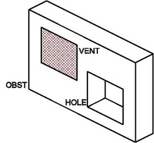
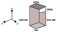
Obstruction, hole and vent
The following table summarizes some HOLE parameters:
| Parameter | Type | Description | Unit | Default |
|---|---|---|---|---|
| XB(6) | Real | Volume, cutout | m | |
| COLOR | String | Color for resulting obstruction | ||
| RGB(3) | Integer | Color for resulting obstruction | ||
| TRANSPARENCY | Real | Transparency of resulting obstruction | ||
| DEVC_ID | String | ID of DEVC that controls HOLE’s existence | ||
| CTRL_ID | String | ID of CTRL that controls HOLE’s existence |
Prescribing a different boundary condition, VENT[edit | edit source]
OBST namelist group can easily prescribe boundary conditions of entire faces of obstacles. But very often you will need to apply a particular boundary condition to a rectangular patch of an entire face or to the exterior boundaries of the computational domain.
The VENT namelist group is used to prescribe these particular boundary conditions:
• on flat faces adjacent to obstructions,
• or exterior boundaries of the computational domain.
For example, the lines:
 &VENT XB=1.0,2.0,2.0,2.0,1.0,3.0, SURF_ID='burner' /
 &OBST XB=0.0,5.0,2.0,3.0,0.0,4.0, SURF_ID='brick wall' /
build a solid obstacle made of brick wall and apply a burner boundary condition to a rectangular patch on the solid face in -y direction.
To set boundary conditions to exterior boundaries of the computational domain proceed as in the following example:
 !!! Computational domain
 &MESH IJK=32,32,16, XB=0.0,1.6,0.0,1.6,0.0,0.8 /
 &MESH IJK=32,32,16, XB=0.0,1.6,0.0,1.6,0.8,1.6 /
 !!! Properties
 &SURF ID='brick wall', COLOR='BROWN' /
 &SURF ID='floor', COLOR='SILVER' /
 &SURF ID='ceiling', COLOR='SLATE GRAY' /
 !!! Solid geometry
 &VENT XB=0.0,0.0,0.0,1.6,0.0,1.4, SURF_ID='brick wall' /
     lower part of -x exterior boundary
 &VENT XB=0.0,0.0,0.0,1.6,1.4,1.6, SURF_ID='OPEN' /
     upper part of -x exterior boundary
 &VENT XB=1.6,1.6,0.0,1.6,0.0,1.6, SURF_ID='OPEN' /
     +x exterior boundary
 &VENT XB=0.0,1.6,0.0,0.0,0.0,1.6, SURF_ID='brick wall' /
     -y exterior boundary
 &VENT XB=0.0,1.6,1.6,1.6,0.0,1.6, SURF_ID='OPEN' /
     +y exterior boundary
 &VENT XB=0.0,1.6,0.0,1.6,0.0,0.0, SURF_ID='floor' /
     -z exterior boundary
 &VENT XB=0.0,1.6,0.0,1.6,1.6,1.6, SURF_ID='ceiling' /
     +z exterior boundary
The result is shown in Figure [fig:Setting-exterior-boundaries].
A shortcut exists to select mesh boundaries: the MB parameter. This manual will not cover it because it leads to error and confusion when employed with multiple meshes.
Note that:
• Only one VENT may be specified for any given wall cell. If additional VENT lines are specified for a given wall cell, FDS will output a warning message and ignore the subsequent lines. The first defined VENT will be applied: first-come, first-served.
• VENT overrides the boundary condition defined by the underlying obstruction: VENT boundary condition wins on OBST boundary condition.
• A VENT must always be attached to a solid obstruction or exterior boundaries of the computational domain: a flying VENT is not allowed.
• If FDS outputs an error message requesting that the orientation of a VENT be specified, check to make sure that the VENT is a plane and that it is not buried within a solid obstruction.
The following table summarizes some VENT parameters:
| Parameter | Type | Description | Unit | Default |
|---|---|---|---|---|
| XB(6) | Real | Face | m | |
| PBX, PBY, PBZ | Real | Plane | m | |
| IOR | Integer | Index of orientation | ||
| SURF_ID | String | Set boundary condition | ‘INERT’ | |
| DEVC_ID | String | ID of DEVC that controls VENT’s existence | ||
| CTRL_ID | String | ID of CTRL that controls VENT’s existence |
Default boundary condition[edit | edit source]
INERT is the default SURF boundary condition for all solid surfaces and the exterior boundary of the computational domain, if not otherwise specified.
If you want to change the default boundary condition, set SURF_DEFAULT parameter on the MISC line. For example:
&MISC SURF_DEFAULT='steel' /
If the default boundary condition is desired for the faces of an obstruction, then SURF_ID* need not be set. For example:
&OBST XB=2.3,4.5,1.3,4.8,0.0,9.2 /
builds a solid obstruction and apply the default surface type to all its faces.
The same is true for a VENT:
&VENT XB=2.3,4.5,1.3,4.8,0.0,0,0 /
How thick is a wall?[edit | edit source]
The lines:
 &MATL ID='brick', CONDUCTIVITY=0.69, SPECIFIC_HEAT=0.84,
     DENSITY=1600. / material
 &SURF ID='brick wall', MATL_ID(1,1)= 'brick', THICKNESS= 0.1 /
     boundary condition
 &OBST XB=0.,10.,0.,.2,0.0,2.7, SURF_ID='brick wall' /
     solid obstruction
first define a brick material and describe a brick wall boundary condition, then build a solid obstruction applying the brick wall surface type to all its faces.
If you carefully examine the prescriptions:
• The OBST object is 10 m long, 2.7 m high, and 0.2 m thick in the y direction.
• The brick wall boundary condition (SURF line) prescribe a 0.1 m thicknesses for the same wall.
At first sight, these two parameters seem in contradiction.
But, if you remember what was anticipated in Section [sec:Each-model-its-data], the THICKNESS parameter indicated by the SURF line, does not need to match the XB dimensions of the solid obstruction prescribed by OBST.
In fact, the two parameters are independent from each other:
• The OBST line describes the overall geometric structure of a solid that obstacles the gas phase flow: it provides data to the hydrodynamic model.
• The SURF line describes the characteristics of the surfaces of the solid, used to provide a reasonable bounding surface temperature for the gas phase calculation: it provides data to the solid heat transfer model.
When a SURF boundary condition is applied to the faces of a solid obstruction, FDS performs a separate one-dimensional heat transfer calculation at each face of the solid, using the THICKNESS parameter. There is no communication among the faces.
Obviously, this is not an ideal way to perform solid phase heat transfer, but that’s currently beyond FDS scope!
Thin sheet obstructions[edit | edit source]
Obstructions can be flat. Often, thin sheets, like a window, form a barrier, but if the numerical mesh is coarse relative to the thickness of the barrier, the obstruction might be unnecessarily large if it is assumed to be one layer of mesh cells thick.
All faces of an obstruction are shifted to the closest mesh cell. If the obstruction is very thin, the two faces may be approximated on the same cell face.
FDS and Smokeview render this obstruction as a thin sheet, but it is allowed to have thermally thick boundary conditions, in other words a not null THICKNESS of the applied SURF.
A thin sheet obstruction can only have one velocity vector on its face, thus a gas cannot be injected reliably from a thin obstruction because whatever is pushed from one side is necessarily pulled from the other. For full functionality, the obstruction should be specified to be at least one mesh cell thick.
Thin sheet obstructions work fine as flow barriers, but other features are fragile and should be used with caution.
To prevent FDS from allowing thin sheet obstructions, set THICKEN_OBSTRUCTIONS=.TRUE. on the MISC line, or THICKEN=.TRUE. on each OBST line for which the thin sheet assumption is not allowed.
Activating and deactivating objects[edit | edit source]
By default the objects and their prescribed boundary conditions are activated and come to existence when the calculation starts, then they are deactivated and disappear when the calculation ends.
If needed, activation and deactivation times of single OBST, VENT and HOLE can be prescribed by a control logic, as explained in Chapter [cha:Devices-and-control-logic].
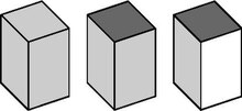
Stair stepping complex geometries[edit | edit source]
The efficiency of FDS is due to the simplicity of its numerical mesh. However, there are situations in which certain geometric features do not conform to the rectangular mesh, such as a sloped ceiling or roof. In these cases, construct the curved geometry using rectangular obstructions, a process sometimes called stair stepping.
A concern is that the stair stepping changes the flow pattern near the wall. To lessen the impact of stair stepping on the flow field near the wall, prescribe the parameter SAWTOOTHSAWTOOTH=.FALSE. on each OBST line that makes up the stair stepped obstruction. The effect of this parameter is to prevent vorticity from being generated at sharp corners, in effect smoothing out the jagged steps that make up the obstruction.
For example, the lines:
 &OBST XB=0.00, 0.05,-0.01, 0.01, 0.00, 0.05,
     SAWTOOTH=.FALSE., COLOR='GREEN' /
 &OBST XB=0.05, 0.10,-0.01, 0.01, 0.00, 0.10,
     SAWTOOTH=.FALSE., COLOR='GREEN' /
 &OBST XB= 0.10, 0.15,-0.01, 0.01, 0.05, 0.15,
     SAWTOOTH=.FALSE., COLOR='GREEN' /
 ...
 &OBST XB=0.00, 0.05,-0.01, 0.01, 0.05, 0.10,
     SAWTOOTH=.TRUE., COLOR='TEAL' /
 &OBST XB=0.05, 0.10,-0.01, 0.01, 0.10, 0.15,
     SAWTOOTH=.TRUE., COLOR='TEAL' /
 &OBST XB=0.10, 0.15,-0.01, 0.01, 0.15, 0.20,
     SAWTOOTH=.TRUE., COLOR='TEAL' /
 ...
create a two sided oblique wall. The resulting flow is shown in Figure [fig:SAWTOOTH].

This is not a complete solution of the problem, but it does provide a simple way of ensuring that the flow field around a non-rectangular obstruction is not inhibited by extra drag created at sharp corners.
Coloring individual objects[edit | edit source]
Objects may be colored individually, overriding SURF prescription, by specifying a COLOR or RGB value on the respective OBST or VENT line:
&OBST XB=..., SURF_ID='carpet', COLOR='INDIGO' /
This is not recommended. As explained in Section [sec:Coloring-boundary-conditions], it is much better to assign a color to each boundary condition.
Making burning solids disappear[edit | edit source]
If a burning object is to disappear from the calculation once it is consumed, set BURN_AWAYBURN_AWAY=.TRUE. on the corresponding SURF line. The solid object disappears from the calculation cell by cell, as the mass contained by each mesh cells is consumed either by the pyrolysis reactions or by the prescribed HRR. The mass of each mesh cell is the cell face area multiplied by the surface density of the SURF type.
An example:
 &SURF ID='stuff', MATL_ID(1:2,1)='fabric','foam',
     THICKNESS(1:2)=0.01,0.1, BURN_AWAY=.TRUE. /
Keep in mind the following issues:
• For reacting surfaces, the surface density is computed as a sum of the layer densities multiplied by the layer thicknesses. This value can be overridden by setting SURFACE_DENSITY on the SURF line.
• For surfaces with prescribed HRRPUA, add SURFACE_DENSITY parameter as this is the only way of defining the mass of the object.
• Use BURN_AWAY parameter cautiously. If an object has the potential of burning away, a significant amount of extra memory has to be set aside to store additional surface information as the rectangular block is eaten away.
• If BURN_AWAY is prescribed, the SURF should be applied to the entire object, not just to a face of the object, because it would be unclear how to handle edges of solid obstructions that have different SURF_IDs on different faces.
See [FDS5 user’s guide] for broader discussion on the topic.
- Remove From My Forums
-
Question
-
Hi.
I’m setting up a Windows HPC Server 2008 R2 SP1 cluster (HPC Pack 2008 R2 SP2). It contains one Head node and five workstations. The purpose of it is to run Abaqus jobs on the HPC. When running larger jobs (abaqus -job «jobname»
-cpus 8 -input CCshort_layup_FO_load.inp) (smaller jobs execute successfully) I get the following error messages:[0] process exited without calling finalize
[1] fatal error
Fatal error in PMPI_Send: Other MPI error, error stack:
PMPI_Send(150)……….: MPI_Send(buf=0x0000000031C10040, count=833568, MPI_BYTE, dest=0, tag=0, comm=0x84000000) failed
MPIDI_CH3I_Progress(235):
RecvFailed(105)………:
ReadFailed(1274)……..: An existing connection was forcibly closed by the remote host. (errno 10054)[2-3] terminated
[0] on client1
C:UsersADMINI~1AppDataLocalTempAdministrator_ava_2692jobname.bat ended prematurely and may have crashed. exit code 0xc0000374All nodes are running Intel Core 2 CPU:s @ 2.13GHz with 2GB of RAM. Workstations have been installed with Windows 7 x64 SP1. Do you have any ideas what it is causing this behavior? Please help me out.
-
Edited by
Friday, November 11, 2011 1:44 PM
-
Edited by
Answers
-
Hi every body!
I’am sorry that i haven’t reply earlier.
The problem that cause my error messages was a corrupt file. The corrupt file was the job file «CCshort_layup_FO_load.inp». When i got a new job file that was working. I nerver received the error messages again.
Thank you all for trying to help me!
Best regards Zorky
Zorky HPC
-
Marked as answer by
Zorky
Tuesday, January 31, 2012 2:37 PM
-
Marked as answer by
![]()
The core of my job submission code is below:
jopt.email_notif = 0;
jopt.toggleleft = left_list(j);
jopt.toggleCausalDir = dir_list(k);
jopt.toggleChoice = choice(l);
jopt.od_number = od_list(i);
jopt.connectivity = 1;
sched = findResource(‘scheduler’, ‘configuration’, ‘NeuroEcon.local’)
set(sched,‘SubmitArguments’, ‘-l walltime=0:20:00’)
pjob = createParallelJob(sched);
set(pjob, ‘FileDependencies’, {‘multiDCMset1.m’})
set(pjob, ‘MaximumNumberOfWorkers’, 1)
set(pjob, ‘MinimumNumberOfWorkers’, 1)
t = createTask(pjob, @multiDCMset1, 1, {jopt})
t_all{1,jj}=t; jj=jj+1;
submit(pjob);
—————————————
The following is the error message I get in the job submission log, after the job finishes running. I don’t understand the error or what could cause it. I do know that the same script runs fine on another person’s computer. Do I need some specific settings to submit parallel jobs?
——————
Node file: /opt/torque/aux//2075983.neuroecon.caltech.edu
Starting SMPD on compute-1-30 …
ssh compute-1-30 «/opt/matlab//bin/mw_smpd» -s -phrase MATLAB -port 25983
All SMPDs launched
«/opt/matlab//bin/mw_mpiexec» -phrase MATLAB -port 25983 -l -n 1
-machinefile /opt/torque/aux//2075983.neuroecon.caltech.edu -genvlist
MDCE_DECODE_FUNCTION,MDCE_STORAGE_LOCATION,MDCE_STORAGE _CONSTRUCTOR,MDCE_JOB_LOCATION,MDCE_DEBUG
«/opt/matlab/bin/worker» -parallel
[0]which: no shopt in
(/opt/matlab/bin:/usr/kerberos/bin:/usr/java/latest/bin:/opt /intel/itac/7.1/bin:/opt/intel/fce/10.1.018/bin:/opt/intel /idbe/10.1.018/bin:/opt/intel/cce/10.1.018/bin:/usr/local /bin:/bin:/usr/bin:/opt/ganglia/bin:/opt/ganglia/sbin:/opt /openmpi/bin/:/opt/maui/bin:/opt/torque/bin:/opt/torque/sbin: /opt/rocks/bin:/opt/rocks/sbin)
[0] < M A T L A B (R) >
[0] Copyright 1984-2009 The MathWorks, Inc.
[0] Version 7.8.0.347 (R2009a) 64-bit (glnxa64)
[0] February 12, 2009
[0]
[0] To get started, type one of these: helpwin, helpdesk, or demo.
[0] For product information, visit www.mathworks.com.
[0]
job aborted:
rank: node: exit code[: error message]
0: compute-1-30: -2: application called MPI_Abort(MPI_COMM_WORLD, 42) —
process 0
Stopping SMPD on compute-1-30 …
ssh compute-1-30 «/opt/matlab//bin/mw_smpd» -shutdown -phrase MATLAB -port
25983
Exiting with code: 42
Answers (0)
See Also
Categories
Community Treasure Hunt
Find the treasures in MATLAB Central and discover how the community can help you!
Start Hunting!
An Error Occurred
Unable to complete the action because of changes made to the page. Reload the page to see its updated state.