The ESP8266 has a few common issues, specially when you are trying to flash a new firmware or uploading scripts.
This is a companion guide to the Home Automation using ESP8266 and Password Protected Web Server eBooks.
Here’s a compilation with some of the most common problems with the ESP8266 and how to fix them.
ESP8266 Troubleshooting – NodeMCU Flasher
Where do I download the NodeMCU flasher?
Go to the NodeMCU flasher GitHub repository and download the flasher for your Windows PC bit version by clicking the button that says “Raw”:
- NodeMCU flasher Windows 64 bits
- NodeMCU flasher Windows 32 bits
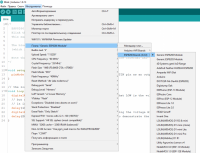
Which settings should I use with the NodeMCU flasher?
The NodeMCU flasher already comes with the right settings by default.
If you have changed some of the settings, I highly recommend that you re-download the NodeMCU flasher.
Here’s my current settings:

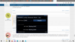
After I press the “Flash” button nothing happens, the NodeMCU flasher doesn’t start the flashing process
If you pressed the “Flash” button and nothing happens… It means one of these two things:
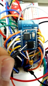
- Problem 1 – Your ESP isn’t in flash mode (double-check if GPIO 0 is connected to GND on power up)
- Problem 2 – Your FTDI Programmer can’t supply enough current to your ESP

Problem 1 – How to make your ESP go into flash mode:
- Close the NodeMCU flasher window
- Remove power from your ESP8266
- Having your ESP connected like this (double check that GPIO 0 is connected to GND)
- Apply power to your ESP8266 and open the NodeMCU flasher
- Press the “Flash” button
If it’s still saying “Waiting MAC”, then try the following:
- Having the NodeMCU flasher still open
- Connect a wire from your ESP8266 reset pin to GND
- Remove that wire from GND and connect to VCC
Repeat steps 2 and 3 a few times until your ESP reboots and hopefully the NodeMCU flasher can detect your ESP and start the flashing process.
Problem 2 – If your FTDI can’t supply enough current, you might need to buy a new FTDI programmer or power your ESP8266 with an external power supply.
NodeMCU flasher gets stuck at a certain percentage

- Remove power from your ESP+FTDI:
- Close the NodeMCU flasher window
- Plug your ESP+FTDI to your computer again
- Open NodeMCU flasher and try the 19200 baud rate
If this process fails, please repeat the same procedure for the next baud rates (38400, 57600, 74880 and 115200).
I don’t know why, but at least 5 people faced the same problem and this trick solved it. So at a baud rate of 57600 or 115200 I think it will flash 100%. I don’t have any logical explanation, since this is not very common.
How does the NodeMCU flasher should look after a successful flash?
It should have a green arrow in the bottom left.

Unbricking the FTDI Programmer on Windows PC
If you have a brand new FTDI Programmer and you need to install your FTDI drivers on Windows, visit this website for the official drivers: http://www.ftdichip.com/Drivers/VCP.htm.
In alternative, you can contact the seller that sold you the FTDI Programmer.
If you’re having trouble installing the FTDI drivers on Windows 7/8/8.1/10 it’s very likely that FTDI is bricked.
Follow this tutorial to fix that: http://youtu.be/SPdSKT6KdF8.
In the video I mentioned earlier, the guy tells you to download the drivers from the FTDI website, read carefully the YouTube description of his video to find all the links. Here’s the drivers you need: http://www.ftdichip.com/Drivers/CDM/CDM%20v2.12.00%20WHQL%20Certified.zip
ESP8266 Troubleshooting – ESPlorer IDE
ESPlorer IDE Error: only one tcp server allowed
This means that you tried to upload multiple scripts and you ESP is still running the old script with a web server. To fix it, you simply need to send these commands to delete all the files and restart your ESP:
- file.format()
- node.restart()
Upload the script again and name it ‘init.lua’ and you shouldn’t see that error again.
ESPlorer IDE Error: can’t autodetect firmware
and
ESPlorer IDE Error: Waiting answer from ESP – Timeout reached. Command aborted.Waiting answer from ESP – Timeout reached. Command aborted.

This sounds like your ESP it’s still in flash mode. How to make your ESP go into user mode:
- Close the ESPlorer IDE connection
- Remove power from your ESP8266
- Having your ESP with GPIO 0 connected to VCC
- Apply power to your ESP8266 and re-establish the connection with ESPlorer IDE
If it’s still saying “can’t autodetect firmware”, then try the following:
- Having the ESPlorer IDE connection still printing “…..”
- Connect a wire from your ESP8266 reset pin to GND
- Remove that wire from GND and connect to VCC
Repeat steps 2 and 3 a few times until your ESP reboots and hopefully the ESPlorer IDE can detect your ESP.
My code disappears when I restart the ESP8266
If you upload a script to your ESP and when you restart it your ESP doesn’t do anything. It means that your ESP couldn’t find the script or it occurred a memory issue.
This can be solved like this:
- You didn’t save your script with this exact name ‘init.lua’. Re-uploading the same script, but with the ‘init.lua’ name should solve your problem
- It can be a memory issue. Re-flashing the ESP with NodeMCU flasher usually solves that problem
Finding the ESP8266 IP Address
Before you start make sure you check these two items:
- Verify that the script uploaded to your ESP has the right network credentials
- Make sure your ESP is near your router
Here’s what you can do to find the IP address:
Solution 1 – Sending a command with the ESPlorer IDE
- Send the command “print(wifi.sta.getip())” with the ESPlorer IDE and it should print your IP Address
![]()
Solution 2 – Install an IP Scanner Software
- An IP Scanner software searches for all the devices in your network
- Download this free software:
- Windows PC: www.advanced-ip-scanner.com
- MAC OS X, Windows or Linux: http://angryip.org
- Install one of these softwares (while having your ESP running with that web server script)
- Open the IP Scanner software and click “Scan”
- Let that process finish (it can take a couple of minutes)
In my case, it found my ESP. Now if I type 192.168.1.95 in my browser I can see the ESP web server.

ESP8266 Troubleshooting – Arduino IDE
I can’t upload scripts to my ESP8266 using the Arduino IDE
How to make your ESP go into upload mode when using the Arduino IDE:
- Remove power from your ESP8266
- Having your ESP connected like this (double check that GPIO 0 is connected to GND)
- Apply power to your ESP8266 and open the Arduino IDE
- Press the “Upload” button
Did you experience other problems?
Please leave a comment below, so I can update the troubleshooting guide with more problems and solutions.
Thanks for reading,
-Rui Santos
-
#1
Очень прошу помочь!!!!
Проблема в следующем: на али приобрел плату esp8266 12E и usb-ttl адаптер установил все необходимые драйвера, библиотеки для платы esp8266. Все по инструкции, попытался залить простой скетч Blink появилось сообщение об ошибке: «error: espcomm_upload_mem failed, error: espcomm_upload_mem failed», при этом плату было видно среди подключенных по Wi-Fi устройств. Искал пути решения, перепробовал куча разных способов, но безрезультатно. на АТ команды через arduino — реакции никакой. После долгих манипуляций установи NODEMCU FLASHER он определил плату (MAC) и без проблем залил «какую-то» прошивку, после повторно пробовал, через arduino без результатов. Пробовал запитывать от внешнего источника припаяв толстые провода, проблемма осталась. После нескольких попыток прошивки плата пропала из устройств, подключенных по Wi-Fi и NODEMCU FLASHER ее не видит больше, перезагружал плату пробовал на другом компьютере реакции — нет. Я решил, что плата была неисправна изначально.
Спустя некоторое время мне пришла из Китая новая плата NodeMcu V3 Lua WI-FI установив драйвера для CH340G, я подключил ее к компьютеру и попытался залить скетч Blink появилась ошибка:
Uploading 226384 bytes from to flash at 0x00000000
warning: espcomm_send_command: didn’t receive command response
warning: espcomm_send_command(FLASH_DOWNLOAD_BEGIN) failed
error: espcomm_upload_mem failed
error: espcomm_upload_mem failed
скорость usb порта выставлена 11520, плата выбрана верная NODEMCU 1.0, FLASH SIZE 4M
Я пробовал на другом компьютере перепрошить ошибка та же.
При включении платы один раз мигает светодиод, среди устройств wi-fi NodeMcu V3 Lua не определяется, программа NODEMCU FLASHER определяет MAC платы, при загрузке мигает два раза синий светодиод.
Прошу Вас помогите! Я не исключаю, что у меня руки из жопы растут, но перепробовал кучу различных вариантов ничего не помогает, предположить, что вторая плата бракованная — вряд ли, с питанием тоже мало вероятно, поскольку на предыдущую плату подавал на прямую 3.3В толстыми проводами. Я читал, что сама плата может приходить пустой и в неё необходимо залить прошивку, но какую, и чем она поможет при заливке скетчей. За ранее всем большое спасибо за понимание!
-
#2
Очень прошу помочь!!!!
При включении платы один раз мигает светодиод, среди устройств wi-fi NodeMcu V3 Lua не определяется, программа NODEMCU FLASHER определяет MAC платы, при загрузке мигает два раза синий светодиод.
Прошу Вас помогите! Я не исключаю, что у меня руки из жопы растут, но перепробовал кучу различных вариантов ничего не помогает, предположить, что вторая плата бракованная — вряд ли, с питанием тоже мало вероятно, поскольку на предыдущую плату подавал на прямую 3.3В толстыми проводами. Я читал, что сама плата может приходить пустой и в неё необходимо залить прошивку, но какую, и чем она поможет при заливке скетчей. За ранее всем большое спасибо за понимание!
1) При загрузке в NODEMCU FLASHER надо грузить два файла (или три) в первый раз. Потом третий файл можно не грузить.
Третий (или второй для луа) файл это esp_init_data_default.bin его грузите с адреса 0x3FC000 для ESP12.
——————
если грузите lua то будет два файла
с адреса 0x0000 — прошивка луа и esp_init_data_default.bin
—————
если бинарную прошивку то обычно два файла с 0x0000 и не с нуля (обычно с 0x10000 )(третий лишь один раз)
=======================
после загрузки обычно надо нажать ресет для работы
===========================
при этом включите терминальную программу и посмотрите что говорит ESP на скорости 74880 для этого используйте TeraTerm.
====================
Если не работает можно попробовать переключить режим SPI с QIO на DIO в флешере
-
#3
1) При загрузке в NODEMCU FLASHER надо грузить два файла (или три) в первый раз. Потом третий файл можно не грузить.
Третий (или второй для луа) файл это esp_init_data_default.bin его грузите с адреса 0x3FC000 для ESP12.
——————
если грузите lua то будет два файла
с адреса 0x0000 — прошивка луа и esp_init_data_default.bin
—————
если бинарную прошивку то обычно два файла с 0x0000 и не с нуля (обычно с 0x10000 )(третий лишь один раз)
=======================
после загрузки обычно надо нажать ресет для работы
===========================
при этом включите терминальную программу и посмотрите что говорит ESP на скорости 74880 для этого используйте TeraTerm.
====================
Если не работает можно попробовать переключить режим SPI с QIO на DIO в флешере
Дело в том, что у меня не получается ни одну прошивку залить, если через NODEMCU FLASHER пробовать: вначале мигает много раз синий светодиод, начинается загрузка, загрузка зависает и пишет в логах: Error:Set ESP8266 Address timeout.
И в подключенных устройствах платы не видно. Пробовал через разные usb порты прошивать, безрезультатно(
-
#4
Дело в том, что у меня не получается ни одну прошивку залить, если через NODEMCU FLASHER пробовать: вначале мигает много раз синий светодиод, начинается загрузка, загрузка зависает и пишет в логах: Error:Set ESP8266 Address timeout.
И в подключенных устройствах платы не видно. Пробовал через разные usb порты прошивать, безрезультатно(
есть два софта ESPRESSIF DOWNLOAD TOOLS и NODEMCU FIRMWARE PROGRAMMER.
Первый универсальный и позволяет посмотреть параметры flash и создать файл параметров для WIFI.
Второй проще.
Первым посмотрите что работает а что нет.
Пишите вторым если первым будет сложно
——————————————
Какие устанавливаете параметры?
Что именно загружаете?
Какой размер загружаемого файла показывает flasher
-
#5
есть два софта ESPRESSIF DOWNLOAD TOOLS и NODEMCU FIRMWARE PROGRAMMER.
Первый универсальный и позволяет посмотреть параметры flash и создать файл параметров для WIFI.
Второй проще.
Первым посмотрите что работает а что нет.
Пишите вторым если первым будет сложно
——————————————
Какие устанавливаете параметры?
Что именно загружаете?
Какой размер загружаемого файла показывает flasher
NODEMCU FLASHER параметры:
Baudrate: 115200 (пробовал менять скорость)
Flash size: 4М
Flash speed: 40MHz
SPI mode: DIO
загружаю nodemcu_float_0.9.6-dev_20150704.bin (пробовал и другие, он просто их не грузит, загрузка встает на 5%, в логах «Error:Set ESP8266 Address timeout.»
Размер прошивки 46768байт
Такое ощущение, что плата не переходит в режим прошивки.
Да и среди доступных WI-FI сетей esp не видно.
——————————————————————————
С ESPRESSIF DOWNLOAD TOOLS пока не разобрался(
Через ESPRESSIF DOWNLOAD TOOLS выдает:
_COM: 6
ESP_ROM_BAUD : 115200
EFUSE_MODE: 1
=============
test baudrate: 9600
test baudrate selection: 0
tout as adc
RF option applied…
test baudrate: 115200
test baudrate selection: 4
test baudrate intop: 115200
test cp intop : 5
C:UsersSystem_1Desktopnodemcu-flasher-masterResourcesBinariesnodemcu_float_0.9.6-dev_20150704.bin
(True, [])
test running : False
serial port opened
Connecting…
chip sync error.
com closed
//У меня кривые руки, перевел в режим программирования плату получил:
test running : False
serial port opened
Connecting…
chip sync ok!
0x3ff00050: 90e40000
0x3ff00054: 0200ac99
0x3ff00058: 0d00b000
0x3ff0005c: 0068c63a
EFUSE MODE : 1
reg0:90e40000
reg1:0200ac99
reg2:0d00b000
reg3:0068c63a
check_err_0: 0b
check_err_1: 00
check_err_2: 00
check_err_3: 02
check_err_4: 0b
====================
EFUSE NORMAL MODE
====================
=========================
CRC IN MODE 1:
crc_calc_res: 13
target crc val: 13
=========================
=========================
CRC IN MODE 1:
crc_calc_res: 228
target crc val: 228
=========================
==================
EFUSE LOG:
======================
EFUSE LOG:
—————
REG0:90E40000
REG1:0200AC99
REG2:0d00b000
REG3:0068C63A
—————-
====================
EFUSE NORMAL MODE
====================
EFUSE CHECK PASS…
=================
reg2>>13: 5
=================
48bit mac
debug:
————————
68 c6 3a ac 99 90
ID FOR XM: 00 D0 00 00 00 0E 40 00
XM_ID: 00D00000000E4000
————————
crc_efuse_4bit: 0
crc_calc_4bit: 0
48bit mac
MAC AP : 6A-C6-3A-AC-99-90
MAC STA: 68-C6-3A-AC-99-90
get mac res: True
(‘tttest uuuuuuuuuuart : uart reg: ‘, 457)
(‘ baudrate: ‘, 115200)
get crystal: 26323200
head: 0 ;total: 0
erase size : 0
я прошу прошения, но мне это не о чем не говорит(
—————————————————————-
При попытке залить «любой» .bin выдает:
crc_efuse_4bit: 0
crc_calc_4bit: 0
48bit mac
[2018-02-06 00:01:06,588][ESP8266Loader_spi[1]][espDownloader.pyo][line:457][ERROR]: ESP8266 Chip flash download error esp_write_flash.
Последнее редактирование: 6 Фев 2018
-
#6
У меня одна esp12 с такими же симптомами валяется.
Изначально гонял и работала отлично. В какой-то момент перестало грузиться. Вернее, начинает и отваливается с ошибкой. Ничего не помогает. Грешу на флеш.
-
#7
-
416.9 KB
Просмотры: 194 -
128 байт
Просмотры: 185
-
#8
@nikolz есть в этом какой то смысл?
ets Jan 8 2013,rst cause:2, boot mode3,7)
load 0x40100000, len 26780, room 16
tail 12
chksum 0x35
ho 0 tail 12 room 4
load 0x3ffe8000, len 1940, room 12
tail 8
chksum 0x57
load 0x3ffe87a0, len 11860, room 0
tail 4
chksum 0x46
csum 0x46
d⸮⸮+խ⸮-+PUUP⸮TT
SD
расшифровке подлежит?
Шил flash download tool 3.6.3
Если шить ардуиной или ардуиновский бинарник то все ок!
Пробовал играться DIO / QIO скоростями порта всякими бланками инитами еразями — не помогает.
Модуль 12е / 4 мб. Раньше этот бинарник в эту плату нормально заливался. Я его даже пробовал залить из под поднятой Http Update — результат fail!
-
#9
@nikolz есть в этом какой то смысл?
ets Jan 8 2013,rst cause:2, boot mode
3,7)
load 0x40100000, len 26780, room 16
tail 12
chksum 0x35
ho 0 tail 12 room 4
load 0x3ffe8000, len 1940, room 12
tail 8
chksum 0x57
load 0x3ffe87a0, len 11860, room 0
tail 4
chksum 0x46
csum 0x46
d⸮⸮+խ⸮-+PUUP⸮TT
SDрасшифровке подлежит?
Шил flash download tool 3.6.3
Если шить ардуиной или ардуиновский бинарник то все ок!
Пробовал играться DIO / QIO скоростями порта всякими бланками инитами еразями — не помогает.
Модуль 12е / 4 мб. Раньше этот бинарник в эту плату нормально заливался. Я его даже пробовал залить из под поднятой Http Update — результат fail!
сделайте то что я написал выше
Файлы я вам выложил прошейте их как нарисовано и сообщите результат.
-
#10
сделайте то что я написал выше
Файлы я вам выложил прошейте их как нарисовано и сообщите результат.
ets Jan 8 2013,rst cause:2, boot mode3,7)
load 0x40100000, len 25932, room 16
tail 12
chksum 0xab
ho 0 tail 12 room 4
load 0x3ffe8000, len 2200, room 12
tail 12
chksum 0xbd
ho 0 tail 12 room 4
load 0x3ffe8898, len 8, room 12
tail 8
chksum 0x51
csum 0x51
rf cal sector: 1019
rf[112] : 00
rf[113] : 00
rf[114] : 01
w_flash
SD⸮⸮⸮⸮⸮Lˀ⸮S@Nܭ1YHV7T
⸮
на 115200
NodeMCU custom build by frightanic.com
branch: master
commit: 7b83bbb2ea134cd85ac9d63108603cc02c4e20f7
SSL: false
modules: adc,bit,file,gpio,i2c,mqtt,net,node,ow,rtctime,sntp,spi,tmr,uart,wifi
build built on: 2016-10-16 07:05
powered by Lua 5.1.4 on SDK 1.5.4.1(39cb9a32)
lua: cannot open init.lua
>
-
#11
ets Jan 8 2013,rst cause:2, boot mode
3,7)
load 0x40100000, len 25932, room 16
tail 12
chksum 0xab
ho 0 tail 12 room 4
load 0x3ffe8000, len 2200, room 12
tail 12
chksum 0xbd
ho 0 tail 12 room 4
load 0x3ffe8898, len 8, room 12
tail 8
chksum 0x51
csum 0x51
rf cal sector: 1019
rf[112] : 00
rf[113] : 00
rf[114] : 01
w_flashSD⸮⸮⸮⸮⸮Lˀ⸮S@Nܭ1YHV7T
⸮
на 115200
NodeMCU custom build by frightanic.com
branch: master
commit: 7b83bbb2ea134cd85ac9d63108603cc02c4e20f7
SSL: false
modules: adc,bit,file,gpio,i2c,mqtt,net,node,ow,rtctime,sntp,spi,tmr,uart,wifi
build built on: 2016-10-16 07:05
powered by Lua 5.1.4 on SDK 1.5.4.1(39cb9a32)
lua: cannot open init.lua
>
Т е луа загружена и работает.
Модуль у Вас нормальный.
-
#12
Я ж говорю в дурине работает, и луа грузится, а вот левый рабочий (точно) бинарник после загрузки выдает ересь. Хотя у других он же грузится и работает. Вопрос — прошивка модуля может изменить какие либо внутренние настройки чипа, которые препятствуют в дальнейшем правильной работе (загрузке) некоторых программ?
-
#13
Я ж говорю в дурине работает, и луа грузится, а вот левый рабочий (точно) бинарник после загрузки выдает ересь. Хотя у других он же грузится и работает. Вопрос — прошивка модуля может изменить какие либо внутренние настройки чипа, которые препятствуют в дальнейшем правильной работе (загрузке) некоторых программ?
Это к тому кто этот бинарик делал или к гадалки.
А еще лучше начните изучать а не собирать халяву.
-
#14
Авторы бинарника тоже руками разводят
-
#15
У меня не прошивается esp8266 nodemcu v3
Are your ESP8266 flash attempts failing? Or perhaps not working at all anymore? Getting that annoying “Invalid head of packet” exception?
I have. Very frustrating…
And there aren’t many answers to be found on-line. What really got me steaming was the “Fatal error” messages at 115200 baud after I thought the flash completed properly. I have been there.
Over and over again…
Just when I was ready to give up…after many, many flash attempts, a flash will actually succeed. You think everything is good again, but the problem just keeps coming back…
What is wrong? Is this just a cheap Chinese trinket? An illusion of the Holy Grail? The ESP8266 specs look great. With such a cheap price tag that sucked you in? Or is there something your doing wrong?
Here is what I have found to be the problem…
And yes, there is a solution.
What many of us have experienced wit these ESP8266 modules, especially those that like to tinker and flash often, is the very low flash cycle count that the memory chips shipped with many of these modules will tolerate before failing. In my experience, flash failures start after only 20 flash cycles or so.
Then it only gets worse from that point on.
The good news is that the memory chips are not difficult to replace. And they are cheap when you order them with free shipping from the slow boat from China. You should be able to find them on AliExpress or your other favorite source. Here are some recent quotes for the different chips found on ESP8266 modules:
| Description | Flash ID | Size | Recent Price (USD) | |
|---|---|---|---|---|
| 1 | Winbond W25Q40 | 1340ef | 512 KByte | 0.32 each 7.85 (per 25) |
| 2 | GigaDevice GD25Q40 | 1340c8 | 512 KByte | 0.32 each 7.85 (per 25) |
| 3 | Winbond W25Q32 | 1640ef | 4 MByte | 0.42 each 4.14 (per 10) |
From looking at the firmware binary header, it looks like the flashes are made for a 512 KByte flash chip (byte 3 upper 4 bits are 0). This would suggest that CURRENTLY, all that is used with the ESP8266 is 512 KBytes.
That is what I am using to replace the flash chip when they start to fail intolerably. I have recently replaced a 4MByte flash chip with a 512 KByte component, it worked flawlessly. With the same amount of space free for the application. You can clearly see that the ESP8266 SDK indicates the maximum firmware size as 512 KBytes.
I have been using the ESP8266-12 modules. The only added step needed for flash chip replacement from an ESP8266-01 is that the golden metal case must be removed to gain access to the SPI memory chip. This is not impossible, you just have to take your time, be patient, and careful.
I use a razor blade to pop the cover off. You just have to score the crease where the metal case meets the PCB. Only do this on the edge that is away from the PCB antenna. This minimizes the risk of damaging something. Eventually, the blade will breach the case bonding. When it starts to give, the rest of the cover will soon separate from the module – cover removed!
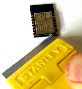
Take it slow so you do not cut yourself, damage the module, or snap the blade. I use a blade with a safety cover. It only require 5-10 minutes to remove the cover in this manner. I have done it to two modules so far with no damage incurred. I have seen some folks use a heat gun to remove the cover. This is too risky in my opinion.
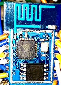
The SPI memory chip will be the obvious 8-pin device. Not to worry. While the ESP8266 would be very challenging to remove, not so with the memory chip. The pins are larger than the ESP8266, making them easier to remove. Just spot apply a hot soldering iron tip to each pin with a pointed object used to lift the pin while the heat is applied. One pin at a time. I found that a breadboard jumper to work for this purpose.
When you have the chip removed and are ready to install the new chip, remember to use the same orientation. A small dot on the chip identifies pin one. Just make a note before removing the old chip for reference. And, obviously, limit the amount of heat applied to each pin.
I am currently using my replacement SPI chips for development and have a decent supply on hand (only 32 cents per chip) to focus on project development, free from the agony of squandering time over recurring flash failures.
I’ll give an update when the replacement chips start to fail to flash. Hopefully, there will be an improvement from the original chips. More flash cycles before the first failure. We shall see. But I can live with it knowing a chip swap will chase this demon away, at least for a while.
Hope that you find this information useful…

Share This:
Social tagging: ESP8266 flash failures > ESP8266 will not flash > How to unbrick ESP8266 > Invalid head of packet

Страница 2 из 3
-
Прошивал через Вин7 и Вин10… результат одинаковый…
-
У меня то же самое. Видимо обновления из одной бочки льются
FT232 шьет. -
А такой
тоже не шьёт?У меня шьёт даже без нажатия на кнопки Prog -
—————————————————————-
Сегодня пробовал шить через usb-ttl CP210X через nodemcu-flasher и с помощью flash_download_tools_v3.6.3 результат одинаковый (MAC определяет после минуты уходит в аут)test offset : 0 0x0
case ok
test offset : 4177920 0x3fc000
case ok
======
CONNECT BAUD: 115200
============
….._____….._____….._____….._____….._____….._____….._____….._____….._____….._____[2018-02-07 21:22:43,961][ESP8266Loader_spi[1]][espDownloader.pyo][line:351][ERROR]: Chip sync error: Failed to connect to ESP8266: Timed out waiting for packet header
[2018-02-07 21:22:43,961][ESP8266Loader_spi[1]][espDownloader.pyo][line:439][ERROR]: ESP8266 Chip sync error esp_sync_blocking.Завтра попробую прошить с других машин, хотя вряд ли это поможет. Уже склонен заказать FT232))
-
Вы правильно заводите режим прошивки?
-
Вроде как да..кнопки: flash и rst про них идет речь?
-
Про них. Держите Флаш и подаете питание.
-
У вас NodeMCU? Тогда маленький бинарник надо шить по адресу 0x3fc000. Хотя вы правильно шьете.
-
Я сегодня шил без Флэша.node mcu через nodemcu flasher
-
да у меня NodeMCU, пробовал держать flash и питание подавать, в режим программирования входит, но не шьется((
-
Это как — входит но не шьется?
-
У меня глупый вопрос: можно ли убить плату неправильной прошивкой или нет?
Мне пришел новый модуль NODEMCU его я планирую прошивать, через Arduino IDE. Прежде чем заливать в плату какие либо скетчи, требуется какая либо подготовка модуля? или достаточно подключить к компьютеру, перевести плату в режим программирования и прошивать через arduino.
и еще один глупый вопрос: сама плата nodemcu, которую еще не прошивали (с родной китайской прошивкой) должна определятся в сети как wi-fi точка при подачи на нее питания или нет. -
Мне не удалось убить ни одну плату ни прошивкой ни перепайкой памяти ни просто так.
Проблемы с прошивкой через pl2303 и ch340 появились в декабре.Я бы порекомендовал вам пробовать прошить плату через esptool как я описал в соседней теме, там более подробный лог.
Кстати, nodemcu на чипе ch340.
-
Да, забыл что сказать. Есть у меня плата от одного производителя, которая не шьется ничем и никак — она не заработала сразу. Но иногда определяется, иногда — нет. Иногда начинает шитья, иногда нет. Зависит от того, как её держать в руках и изгиба. Видимо проблемы микротрещин, пайки.
-
Через Ардуинью IDE шьется почти также но есть маленький нюанс.Жмем кнопку Ресет через секунду Прог и не отпускаем ее до того как внизу не появятся желтые точки что означает процесс прошивки а лучше вообще держим кнопку зажатой до конца процесса.Ошибка многих (в том числе и моя была понял не сразу)что сначала идет компиляция причем идет достаточно долго и на этом этапе увидев что процесс пошел многие кнопку отпускают а запись то еще не началась и конечно же она не начнется потому как к ее началу кнопка отпущена.Так что жмите от души.
Вот и мне такая попалась Witty.Вчерась прогрел ее феном может заработает нормально
-
Сегодня пришел новый модуль nodeMCU (от того же продавца). Подключил его к компьютеру сразу определил порт (CH340G), плата появилась среди доступных сетей. Попробовал залить через Arduino ide простой сетч blink и все замечательно загрузка пролетела, даже зажимать ничего не потребовалось.но…не все так просто как оказалось:
скетч:
#define led1 1
void setup() {
pinMode(led1, OUTPUT);
}
void loop() {
digitalWrite(led1, HIGH);
delay(500);
digitalWrite(led1, LOW);
delay(500);
}
результат:
Uploading 226416 bytes from to flash at 0x00000000
………………………………………………………………………………………………………………………………………………………………………………………………….
Загрузка завершенаподключаю светодиод к D1, и никакой реакции, решил попробовать залить скетч в котором просто выставлял на D1 высокий уровень, прошиваю, ресет и опять ничего, стал проверять ноги — поочередно подключая их к светодиоду и обнаружил, что на D3, D4, D6 (слабо горел), на 5-ой вообще мигал с частотой 2сек. И я опять сел в лужу. Предполагаю, что у меня руки заточены не под то место. Но прошу помочь разобраться, через nodemcu flasher и другие програм. не прошивал, так как вроде проблем при заливке нет.
-
Странно, но даже на AT команды не реагирует(
")
![[IMG]](http://www.avislab.com/blog/wp-content/uploads/2017/04/ESP8266Flasher_1.png)
Страница 2 из 3
The ESP8266 has a few common issues, specially when you are trying to flash a new firmware or uploading scripts.
This is a companion guide to the Home Automation using ESP8266 and Password Protected Web Server eBooks.
Here’s a compilation with some of the most common problems with the ESP8266 and how to fix them.
ESP8266 Troubleshooting – NodeMCU Flasher
Where do I download the NodeMCU flasher?
Go to the NodeMCU flasher GitHub repository and download the flasher for your Windows PC bit version by clicking the button that says “Raw”:
- NodeMCU flasher Windows 64 bits
- NodeMCU flasher Windows 32 bits
Which settings should I use with the NodeMCU flasher?
The NodeMCU flasher already comes with the right settings by default.
If you have changed some of the settings, I highly recommend that you re-download the NodeMCU flasher.
Here’s my current settings:
After I press the “Flash” button nothing happens, the NodeMCU flasher doesn’t start the flashing process
If you pressed the “Flash” button and nothing happens… It means one of these two things:
- Problem 1 – Your ESP isn’t in flash mode (double-check if GPIO 0 is connected to GND on power up)
- Problem 2 – Your FTDI Programmer can’t supply enough current to your ESP
Problem 1 – How to make your ESP go into flash mode:
- Close the NodeMCU flasher window
- Remove power from your ESP8266
- Having your ESP connected like this (double check that GPIO 0 is connected to GND)
- Apply power to your ESP8266 and open the NodeMCU flasher
- Press the “Flash” button
If it’s still saying “Waiting MAC”, then try the following:
- Having the NodeMCU flasher still open
- Connect a wire from your ESP8266 reset pin to GND
- Remove that wire from GND and connect to VCC
Repeat steps 2 and 3 a few times until your ESP reboots and hopefully the NodeMCU flasher can detect your ESP and start the flashing process.
Problem 2 – If your FTDI can’t supply enough current, you might need to buy a new FTDI programmer or power your ESP8266 with an external power supply.
NodeMCU flasher gets stuck at a certain percentage
- Remove power from your ESP+FTDI:
- Close the NodeMCU flasher window
- Plug your ESP+FTDI to your computer again
- Open NodeMCU flasher and try the 19200 baud rate
If this process fails, please repeat the same procedure for the next baud rates (38400, 57600, 74880 and 115200).
I don’t know why, but at least 5 people faced the same problem and this trick solved it. So at a baud rate of 57600 or 115200 I think it will flash 100%. I don’t have any logical explanation, since this is not very common.
How does the NodeMCU flasher should look after a successful flash?
It should have a green arrow in the bottom left.
Unbricking the FTDI Programmer on Windows PC
If you have a brand new FTDI Programmer and you need to install your FTDI drivers on Windows, visit this website for the official drivers: http://www.ftdichip.com/Drivers/VCP.htm.
In alternative, you can contact the seller that sold you the FTDI Programmer.
If you’re having trouble installing the FTDI drivers on Windows 7/8/8.1/10 it’s very likely that FTDI is bricked.
Follow this tutorial to fix that: http://youtu.be/SPdSKT6KdF8.
In the video I mentioned earlier, the guy tells you to download the drivers from the FTDI website, read carefully the YouTube description of his video to find all the links. Here’s the drivers you need: http://www.ftdichip.com/Drivers/CDM/CDM%20v2.12.00%20WHQL%20Certified.zip
ESP8266 Troubleshooting – ESPlorer IDE
ESPlorer IDE Error: only one tcp server allowed
This means that you tried to upload multiple scripts and you ESP is still running the old script with a web server. To fix it, you simply need to send these commands to delete all the files and restart your ESP:
- file.format()
- node.restart()
Upload the script again and name it ‘init.lua’ and you shouldn’t see that error again.
ESPlorer IDE Error: can’t autodetect firmware
and
ESPlorer IDE Error: Waiting answer from ESP – Timeout reached. Command aborted.Waiting answer from ESP – Timeout reached. Command aborted.
This sounds like your ESP it’s still in flash mode. How to make your ESP go into user mode:
- Close the ESPlorer IDE connection
- Remove power from your ESP8266
- Having your ESP with GPIO 0 connected to VCC
- Apply power to your ESP8266 and re-establish the connection with ESPlorer IDE
If it’s still saying “can’t autodetect firmware”, then try the following:
- Having the ESPlorer IDE connection still printing “…..”
- Connect a wire from your ESP8266 reset pin to GND
- Remove that wire from GND and connect to VCC
Repeat steps 2 and 3 a few times until your ESP reboots and hopefully the ESPlorer IDE can detect your ESP.
My code disappears when I restart the ESP8266
If you upload a script to your ESP and when you restart it your ESP doesn’t do anything. It means that your ESP couldn’t find the script or it occurred a memory issue.
This can be solved like this:
- You didn’t save your script with this exact name ‘init.lua’. Re-uploading the same script, but with the ‘init.lua’ name should solve your problem
- It can be a memory issue. Re-flashing the ESP with NodeMCU flasher usually solves that problem
Finding the ESP8266 IP Address
Before you start make sure you check these two items:
- Verify that the script uploaded to your ESP has the right network credentials
- Make sure your ESP is near your router
Here’s what you can do to find the IP address:
Solution 1 – Sending a command with the ESPlorer IDE
- Send the command “print(wifi.sta.getip())” with the ESPlorer IDE and it should print your IP Address
Solution 2 – Install an IP Scanner Software
- An IP Scanner software searches for all the devices in your network
- Download this free software:
- Windows PC: www.advanced-ip-scanner.com
- MAC OS X, Windows or Linux: http://angryip.org
- Install one of these softwares (while having your ESP running with that web server script)
- Open the IP Scanner software and click “Scan”
- Let that process finish (it can take a couple of minutes)
In my case, it found my ESP. Now if I type 192.168.1.95 in my browser I can see the ESP web server.
For More Details: ESP8266 Troubleshooting Guide
Hello,
When I’m trying to upload my sketch to arduino, everything works seems to go smoothly, however at the end of the uploading, there is usually an error.
Sketch uses 241,952 bytes (55%) of program storage space. Maximum is 434,160 bytes.
Global variables use 46,880 bytes (57%) of dynamic memory, leaving 35,040 bytes for local variables. Maximum is 81,920 bytes.
Uploading 246096 bytes from /tmp/build1487447564622711308.tmp/ESPdriver.cpp.bin to flash at 0x00000000
............................................................................................................................................................................................................................................warning: espcomm_send_command: didn't receive command response
warning: espcomm_send_command(FLASH_DOWNLOAD_DATA) failed
warning: espcomm_send_command: didn't receive command response
After this happens, i cannot even attempt to upload sketches, because i immediately get the following error
warning: espcomm_sync failed
error: espcomm_open failed
Then i have to unplug USB-to-serial from my PC, plug it again and try uploading, which usually results in getting error during FLASH_DOWNLOAD_DATA again.
I should add that sometimes, in about 1 per 20 or so tries i can flash, also monitoring Serial, both sending and receiving data works fine. Every time this error happens, it appears at about the same moment (judging by the amount of dots).
I have tried both Arduino IDE with installed ESP8266 from the Board Manager and compiled one from the git by myself, same error.
I am using ESP8266-01 and MicroFTX to communicate with PC (http://jim.sh/ftx/). ESP8266 is powered by YwRobot. My OS is Ubuntu 14.04.
Because my MicroFTX doesn’t support DTR I’m manually resetting and setting GPIO0 low.
Any suggestions on how could I fix this problem?
Thanks
Any suggestions?
EDIT: Using esptool.py, it seems that uploading always stops at 87%. Am I correct that this means the ESP is broken?
EDIT2: However, i managed to flash it using the .bin from arduino esp (not from esptool.py elf2image) and using esptool.py write_flash 0x00000 <the .bin file here>. I am not sure if this is one of the randomly working flashes, but it worked 2 times in a row.
EDIT3: It didnt start working sadly, but I have noticed that the moment of error is persistent among the same binary. So while it was always at 87% before, later it happened at address 0x0003b000 which was 90% and then at 0x00007400 at 90% (it was while writing first file of two into flash). The error from esptool.py is always:
Traceback (most recent call last):
  File "esptool.py", line 547, in <module>
    esp.flash_block(block, seq)
  File "esptool.py", line 204, in flash_block
    struct.pack('<IIII', len(data), seq, 0, 0)+data, ESPROM.checksum(data))[1] != "":
  File "esptool.py", line 107, in command
    raise Exception('Invalid head of packet')
Exception: Invalid head of packet
I have also noticed that almost all sources on the internet use two binary files: 0x00000 and 0x40000 and the file I get from Arduino IDE is 1 binary file .bin, while esptool.py elf2image on the elf generated by IDE generates one file at 0x00000 and one file at 0x01010. Could this be related to the issue?
Want to back this issue? Post a bounty on it! We accept bounties via Bountysource.
-
#159
Господа здравствуйте. Возникла проблема пытаюсь прошить ESP12F, но выдает вот такую ошибку:
Executable segment sizes:
ICACHE : 32768 — flash instruction cache
IROM : 231820 — code in flash (default or ICACHE_FLASH_ATTR)
IRAM : 27613 / 32768 — code in IRAM (IRAM_ATTR, ISRs…)
DATA : 1496 ) — initialized variables (global, static) in RAM/HEAP
RODATA : 992 ) / 81920 — constants (global, static) in RAM/HEAP
BSS : 25608 ) — zeroed variables (global, static) in RAM/HEAP
Скетч использует 261921 байт (27%) памяти устройства. Всего доступно 958448 байт.
Глобальные переменные используют 28096 байт (34%) динамической памяти, оставляя 53824 байт для локальных переменных. Максимум: 81920 байт.
C:UsersVenusAppDataLocalArduino15packagesesp8266toolspython33.7.2-post1/python3 C:UsersVenusAppDataLocalArduino15packagesesp8266hardwareesp82663.0.0/tools/upload.py —chip esp8266 —port COM7 —baud 115200 —before default_reset —after hard_reset write_flash 0x0 C:UsersVenusAppDataLocalTemparduino_build_166446/Blink.ino.bin
esptool.py v3.0
Serial port COM7
Traceback (most recent call last):
File «C:UsersVenusAppDataLocalArduino15packagesesp8266hardwareesp82663.0.0/tools/upload.py», line 66, in <module>
esptool.main(cmdline)
File «C:/Users/Venus/AppData/Local/Arduino15/packages/esp8266/hardware/esp8266/3.0.0/tools/esptoolesptool.py», line 3551, in main
esp = chip_class(each_port, initial_baud, args.trace)
File «C:/Users/Venus/AppData/Local/Arduino15/packages/esp8266/hardware/esp8266/3.0.0/tools/esptoolesptool.py», line 271, in init
self._port = serial.serial_for_url(port)
File «C:/Users/Venus/AppData/Local/Arduino15/packages/esp8266/hardware/esp8266/3.0.0/tools/pyserialserialinit.py», line 90, in serial_for_url
instance.open()
File «C:/Users/Venus/AppData/Local/Arduino15/packages/esp8266/hardware/esp8266/3.0.0/tools/pyserialserialserialwin32.py», line 64, in open
raise SerialException(«could not open port {!r}: {!r}».format(self.portstr, ctypes.WinError()))
serial.serialutil.SerialException: could not open port ‘COM7’: OSError(22, ‘������� �������������� ����������.’, None, 433)
serial.serialutil.SerialException: could not open port ‘COM7’: OSError(22, ‘������� �������������� ����������.’, None, 433)
Именно последние 3 строчки не понятны. Порт компьютер видит, и в ардуино и в диспетчере устройств. Но если я даже пытаюсь просто открыть Монитор порта, вылезает вот такая ошибка — Ошибка открытия последовательного порта «COM7» (Port busy)
Пытался перезагружать и usb порт менял, все бестолку. Можете подсобить?
-
411.7 KB
Просмотры: 8