
Страница 1 из 2
-
Подскажите новичку, пытаюсь залить скетч в esp01s. Залил в esp nonos-sdk2.2.1, проверил AT команды все отрабатывает. В ардуино добавил esp8266 вроде все настроил. При загрузке скетча получаю следующую ошибку:
Скетч использует 288080 байт (30%) памяти устройства. Всего доступно 958448 байт.
Глобальные переменные используют 27252 байт (33%) динамической памяти, оставляя 54668 байт для локальных переменных. Максимум: 81920 байт.
esptool.py v2.7
Serial port COM4
Connecting….
Chip is ESP8266EX
Features: WiFi
Crystal is 26MHz
MAC: 5c:cf:7f:eb:92:cb
Uploading stub…
Running stub…
Stub running…
Manufacturer: 0e
Device: 4014
Detected flash size: 1MB
Hard resetting via RTS pin…
esptool.py v2.7
Serial port COM4
Connecting…….._____….._____….._____….._____….._____….._____…..____Traceback (most recent call last):
File «C:Users1AppDataLocalArduino15packagesesp8266hardwareesp82662.6.0/tools/upload.py», line 25, in <module>
esptool.main(fakeargs)
File «C:/Users/1/AppData/Local/Arduino15/packages/esp8266/hardware/esp8266/2.6.0/tools/esptoolesptool.py», line 2841, in main
esp.connect(args.before)
File «C:/Users/1/AppData/Local/Arduino15/packages/esp8266/hardware/esp8266/2.6.0/tools/esptoolesptool.py», line 483, in connect
raise FatalError(‘Failed to connect to %s: %s’ % (self.CHIP_NAME, last_error))
esptool.FatalError: Failed to connect to ESP8266: Timed out waiting for packet header
_
выбранный последовательный порт _
не существует или плата не подключена к немуЧто я делаю не так?
-
Ничего не говорит ошибка?
-
Да, но перед этим то все нормально. И в процессе светюки мигают, значит связь есть. При прошивке ESP8266 Download Tool подобной ошибки не возникает. Я уже попробовал другой программатор, тоже самое
Думал какая-то хитрость есть в настройках Arduino… -
GPIO 0 на Gnd зажали для прошивки?
-
Обязательно! И коротко пробовал и удерживал. Неужели только у меня такая проблема?
-
Чем прошиваете?Переходник какой?Софт?
Последнее редактирование: 15 ноя 2019
-
один usb-ttl usb-stc-isp с выходом 3.3в, второй вроде для esp с китайского сайта USB-SERIAL CH340. Win10 Arduino 1.8.10.
SDK прошивал flash_download_tools_v3.6.7 все хорошо. Из Arduino ни в какую -
GPIO0 должен быть заземлен до подачи питания то есть модуль включается с уже заземленным GPIO0.Не после а до.Засада обычно здесь. А EN соеденить с 3.3V
-
EN +3.3v постоянно, GPI0 перед включением подаю землю, тогда уходит в режим прошивки иначе нет. Пробовал землю и на весь период прошивки и коротко при включении. Эффект 0
(( -
Твою ж дивизию! Б%*ь!!! Во время Connecting…….._____ положить RST на землю на три секунды! Ну это полный пипец товарищи! Водопроводчики хард/софт делали. Спасибо индусу в комментах ютуба с такой-же траблой. Мде, сколько таких-же бедолаг оказалось в мире как я, два дня жизни на такую хрень угрохал! Интересно, в работе эта хрень также криво будет себя вести? )))))
-
Интересно….А ссылку на видео не дадите?Ну шоб знать на будущее.
-
Пожалуйста —
Коммент от Мухаммеда и ниже корректировка о трех секундах. Мне помогли именно три секунды. Если отпускаю раньше — ошибка.
-
Я новичек, не могли бы вы объяснить еще раз как правильно вгружать
-
Ну перед прошивкой GPIO0 прижать к GND тут или кнопку зажать или проводом пины соединить и в большинстве случаев этого хватает но лучше как оказалось в момент окончания компиляции и начале загрузки когда появляется надпись
жмем Reset 3 секунды как на Ардуино про мини. После этого должно загрузиться
-
пробую, пока не получается
-
Добрый день. Умные голову, помогите п-та. Пытаюсь шить ESP8266 через адаптор (usb к ESP8266 ESP-01Wi-Fi модуль адаптор с CH340G USB к TTL-драйверу, последовательный беспроводной адаптер LDO для Arduino 3,3B), с переключателем на борту.
В логе ошибка:
Arduino: 1.8.15 (Windows 7), Плата:»Generic ESP8266 Module, 80 MHz, Flash, Legacy (new can return nullptr), All SSL ciphers (most compatible), dtr (aka nodemcu), 26 MHz, 40MHz, DOUT (compatible), 1MB (FS:64KB OTA:~470KB), 2, nonos-sdk 2.2.1+100 (190703), v2 Lower Memory, Disabled, None, Only Sketch, 115200″
Executable segment sizes:
IROM : 228624 — code in flash (default or ICACHE_FLASH_ATTR)
IRAM : 26756 / 32768 — code in IRAM (ICACHE_RAM_ATTR, ISRs…)
DATA : 1248 ) — initialized variables (global, static) in RAM/HEAP
RODATA : 688 ) / 81920 — constants (global, static) in RAM/HEAP
BSS : 24880 ) — zeroed variables (global, static) in RAM/HEAP
Скетч использует 257316 байт (26%) памяти устройства. Всего доступно 958448 байт.
Глобальные переменные используют 26816 байт (32%) динамической памяти, оставляя 55104 байт для локальных переменных. Максимум: 81920 байт.
esptool.py v2.8
Serial port COM45
Connecting…….._____….._____….._____….._____….._____….._____…..____Traceback (most recent call last):
File «C:UsersAndreyAppDataLocalArduino15packagesesp8266hardwareesp82662.7.2/tools/upload.py», line 65, in <module>
esptool.main(cmdline)
File «C:/Users/Andrey/AppData/Local/Arduino15/packages/esp8266/hardware/esp8266/2.7.2/tools/esptoolesptool.py», line 2890, in main
esp.connect(args.before)
File «C:/Users/Andrey/AppData/Local/Arduino15/packages/esp8266/hardware/esp8266/2.7.2/tools/esptoolesptool.py», line 483, in connect
raise FatalError(‘Failed to connect to %s: %s’ % (self.CHIP_NAME, last_error))
esptool.FatalError: Failed to connect to ESP8266: Timed out waiting for packet header
_выбранный последовательный порт _
не существует или плата не подключена к нему
Как поправить ? Тоже нужно на землю кидать провод?
-
А порт а диспетчере устройств присутствует? Если да то танцуем дальше с бубном
-
Да, установлен 45 com. У меня нет в адапторе кнопок, есть только переключатель (prog и uart). Буду пробовать еще 3 сек к водопроводному стояку прицепиться
А reset , подпаиваться к ноге RST?
Последнее редактирование: 13 ноя 2021
 Думал какая-то хитрость есть в настройках Arduino…
Страница 1 из 2
Пытаюсь прошить Wemod D1 mini.
В приложении «GyverMatrixOS_v1.15» нажимаю на кнопку «Загрузка» ( Прошивку уже настроил ) и выдаёт ошибку
Arduino: 1.8.10 (Windows 7), Плата:»LOLIN(WEMOS) D1 mini Pro, 80 MHz, Flash, Legacy (new can return nullptr), All SSL ciphers (most compatible), 16MB (FS:14MB OTA:~1019KB), v2 Lower Memory, Disabled, None, Only Sketch, 921600″
In file included from D:DocumentsDesktopGyverMatrixWiFi-masterfirmwareGyverMatrixOS_v1.15GyverMatrixOS_v1.15.ino:132:0:
D:DocumentsArduinolibrariesFastLED/FastLED.h:14:21: note: #pragma message: FastLED version 3.003.002
# pragma message «FastLED version 3.003.002»
^
In file included from D:DocumentsArduinolibrariesFastLED/FastLED.h:65:0,
from D:DocumentsDesktopGyverMatrixWiFi-masterfirmwareGyverMatrixOS_v1.15GyverMatrixOS_v1.15.ino:132:
D:DocumentsArduinolibrariesFastLED/fastspi.h:130:23: note: #pragma message: No hardware SPI pins defined. All SPI access will default to bitbanged output
# pragma message «No hardware SPI pins defined. All SPI access will default to bitbanged output»
^
Executable segment sizes:
IROM : 311104 — code in flash (default or ICACHE_FLASH_ATTR)
IRAM : 27564 / 32768 — code in IRAM (ICACHE_RAM_ATTR, ISRs…)
DATA : 1416 ) — initialized variables (global, static) in RAM/HEAP
RODATA : 2056 ) / 81920 — constants (global, static) in RAM/HEAP
BSS : 31176 ) — zeroed variables (global, static) in RAM/HEAP
Скетч использует 342140 байт (35%) памяти устройства. Всего доступно 958448 байт.
Глобальные переменные используют 34648 байт (42%) динамической памяти, оставляя 47272 байт для локальных переменных. Максимум: 81920 байт.
esptool.py v2.8
Serial port COM3
Traceback (most recent call last):
File «C:Users����AppDataLocalArduino15packagesesp8266hardwareesp82662.6.3/tools/upload.py», line 65, in <module>
esptool.main(cmdline)
File «C:/Users/����/AppData/Local/Arduino15/packages/esp8266/hardware/esp8266/2.6.3/tools/esptoolesptool.py», line 2889, in main
esp = chip_class(each_port, initial_baud, args.trace)
File «C:/Users/����/AppData/Local/Arduino15/packages/esp8266/hardware/esp8266/2.6.3/tools/esptoolesptool.py», line 237, in __init__
self._port = serial.serial_for_url(port)
File «C:/Users/����/AppData/Local/Arduino15/packages/esp8266/hardware/esp8266/2.6.3/tools/pyserialserial__init__.py», line 88, in serial_for_url
instance.open()
File «C:/Users/����/AppData/Local/Arduino15/packages/esp8266/hardware/esp8266/2.6.3/tools/pyserialserialserialwin32.py», line 62, in open
raise SerialException(«could not open port {!r}: {!r}».format(self.portstr, ctypes.WinError()))
serial.serialutil.SerialException: could not open port ‘COM3’: FileNotFoundError(2, ‘�� ������� ����� ��������� ����.’, None, 2)
serial.serialutil.SerialException: could not open port ‘COM3’: FileNotFoundError(2, ‘�� ������� ����� ��������� ����.’, None, 2)
Этот отчёт будет иметь больше информации с
включенной опцией Файл -> Настройки ->
«Показать подробный вывод во время компиляции»
Что делать? Помогите пожалуйста.
Проверка/Оформление/Редактирование: Мякишев Е.А.

|
Черновик |
При попытке загрузить ESP8266 получаю ошибку «espcomm_sync failed». Как решить эту проблему?[1]
Это сообщение информирует о проблеме с загрузкой прошивки на ESP8266 через последовательное соединение. Причина может варьироваться в зависимости от типа модуля, от параметров, выбранных при загрузке, от того, используете ли вы отдельный USB-Serial конвертер, и т.д. То есть одного простого ответа на то, что является основной причиной проблемы, нет. Чтобы найти ее, придется выполнить диагностику.
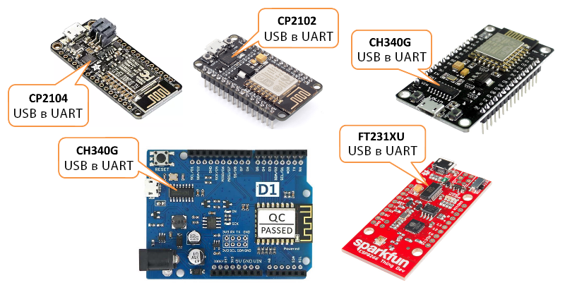
Примечание: Если вы новичок в теме ESP8266 и хотели бы избежать потенциальных проблем с загрузкой прошивки, купите модуль ESP8266 со встроенным конвертером USB-Serial. Это существенно сократит количество факторов (в частности, уменьшит возню с настройками), из-за которых вы можете случайно помешать процессу загрузки.
На картинке ниже показаны платы со встроенным конвертером USB-Serial. Их использование, повторюсь, значительно упростит разработку ваших первых проектов на ESP8266.
Если вы используете «голый» (стандартный) модуль ESP8266 (например, ESP-01 или ESP-12), самостоятельно подключенный к отдельному USB-Serial конвертеру, обязательно проделайте следующее:
- Обеспечьте модуль достаточным питанием
- Подключите контакты GPIO0, GPIO15 и CH_PD при помощи подтягивающих/стягивающих резисторов
- Переведите модуль в режим загрузчика
Более подробно читайте в разделе «Стандартные модули ESP8266» статьи «Платы для аддона ESP8266 для IDE Arduino». На картинке ниже показаны платы без встроенного конвертера USB-Serial:
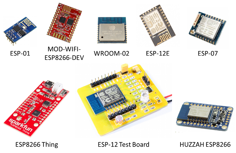
Платы ESP8266 без встроенного конвертера USB-Serial
Предварительные проверки
Чтобы исправить ошибку «espcomm_sync failed», пройдите шаг за шагом инструкцию ниже. Это список решений, ранжированных от самого простого до самого сложного.
1. Прочтите сообщение, показанное в отладочном окне IDE Arduino. Во многих случаях оно предоставляет точную информацию о том, где именно возникла проблема.
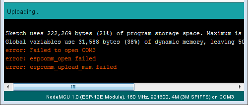
Ошибка «Failed to open COM3»
К примеру, сообщение на картинке выше, говорит, что IDE Arduino не может открыть последовательный порт COM3. Следовательно, нужно проверить, выбран ли в IDE Arduino порт, к которому подключен ваш модуль.
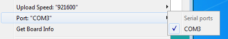
Выбор последовательного порта
2. Если модуль подключен к последовательному порту, но не отвечает как модуль ESP8266, сообщение в отладочном окне будет слегка другим (см. ниже). Если к вашему ПК подключены другие модули, проверьте, что загрузили код на ESP8266, а не на, к примеру, Arduino UNO.
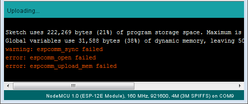
Ошибка «espcomm_sync failed»
3. Чтобы ваш ПК мог общаться с ESP8266, выберите в IDE Arduino правильный модуль ESP8266. Если выбрать неправильный модуль, загрузка прошивки может завершиться неудачей.
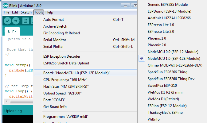
Выбор платы
Выбрать правильную плату нужно для того, чтобы IDE Arduino мог применить правильный «метод сброса» при переключении платы в режим загрузчика. Разные платы используют разные методы сброса. У некоторых плат нет аппаратных компонентов, чтобы выполнить сброс через IDE Arduino. В таком случае плату нужно перевести в режим загрузчика вручную.
4. Кроме того, загрузка прошивки может не удаться из-за слишком высокой скорости передачи данных. Если у вас длинный или некачественный USB-кабель, попробуйте снизить скорость загрузки в меню «Upload Speed».
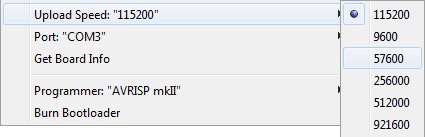
Выбор скорости для передачи данных через последовательное соединение
Дополнительные проверки
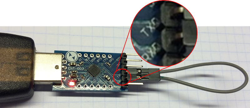
1. Если проблема не исчезла, проверьте, точно ли модуль вошел в режим загрузчика. Для этого нужно подключить к ESP8266 добавочный конвертер USB-Serial, а затем посмотреть на показываемые сообщения.
Итак, для начала подключите контакты RX и GND конвертера к контактам TX и GND на ESP8266, как показано ниже:
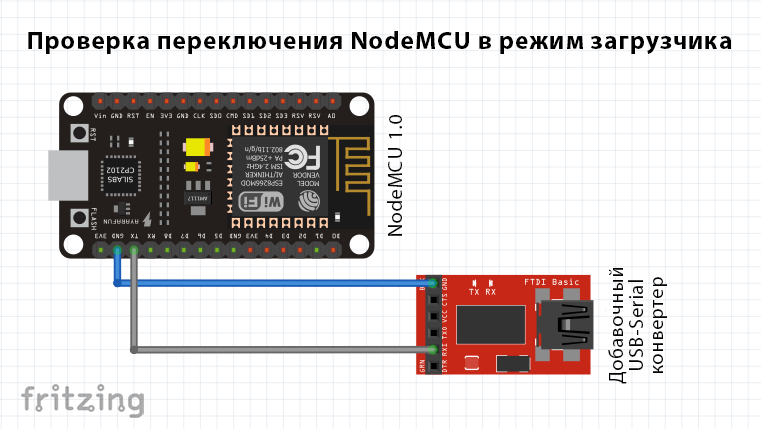
Подключение добавочного USB-Serial конвертера
Затем откройте терминал на скорости 74880 бод и посмотрите, какие сообщения присылает ESP8266 при сбросе, выполняемом для загрузки прошивки. Правильное сообщение должно выглядеть примерно так:
ets Jan 8 2013,rst cause:2, boot mode:(1,7)
Если у вас появилось такое же сообщение, но с другими значениями, то расшифровать его можно при помощи таблицы из этой статьи (см. третью таблицу в разделе «Сообщения о режимах запуска и причине сброса/перезагрузки»). Ключевая информация содержится в первой цифре, находящейся в скобочках рядом с надписью «boot mode», как показано на картинке ниже:
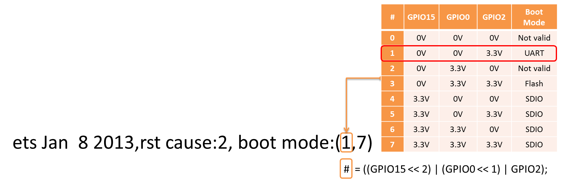
Расшифровка сообщения о режиме запуска
К примеру, сообщение «boot mode (3, 3)» информирует, что контакты GPIO2 и GPIO0 выставлены на HIGH, а GPIO15 – на LOW. Это настройка для нормальной работы модуля (т.е. выполнения программы, записанной на flash-память), но не для режима загрузчика (т.е. программирования flash-памяти).
Примечание: Если выполнить этот шаг неправильно, вы не сможете загрузить прошивку на модуль через последовательный порт.
2. Вы убедились, что модуль находится в режиме загрузчика, но загрузить прошивку по-прежнему не удается. Если вы используете внешний конвертер USB-Serial, проверьте, правильно ли он работает, закольцевав выход на вход. Этой очень простая проверка. Просто подключите друг к другу контакты RX и TX на конвертере как показано на картинке ниже. Затем откройте монитор порта и впишите там несколько символов. Если все в порядке, то все написанные вами символы должны сразу же появится в мониторе порта. Чтобы выполнить такую проверку на модуле со встроенным USB-Serial конвертером, может понадобиться разрушить некоторые дорожки на печатной плате. Я бы сделал это лишь в полном отчаянии. Лучше попробуйте способы, описываемые еще ниже.
3. Еще один способ – это просмотр более детальных отладочных сообщений. Кликните в IDE Arduino на Файл > Настройки (File > Preferences) и поставьте галочку рядом с пунктом «Показать подробный вывод: Загрузка» («Show verbose output during: upload»). Чтобы загрузка прошивки была успешной, эти логи должны выглядеть примерно так:
C:UsersKrzysztofAppDataLocalArduino15packagesesp8266toolsesptool0.4.8/esptool.exe -vv -cd ck -cb 115200 -cp COM3 -ca 0x00000 -cf C:UsersKRZYSZ~1AppDataLocalTempbuild7e44b372385012e74d64fb272d24b802.tmp/Blink.ino.bin esptool v0.4.8 - (c) 2014 Ch. Klippel <ck@atelier-klippel.de> setting board to ck setting baudrate from 115200 to 115200 setting port from COM1 to COM3 setting address from 0x00000000 to 0x00000000 espcomm_upload_file espcomm_upload_mem setting serial port timeouts to 1000 ms opening bootloader resetting board trying to connect flush start setting serial port timeouts to 1 ms setting serial port timeouts to 1000 ms flush complete espcomm_send_command: sending command header espcomm_send_command: sending command payload read 0, requested 1 trying to connect flush start setting serial port timeouts to 1 ms setting serial port timeouts to 1000 ms flush complete espcomm_send_command: sending command header espcomm_send_command: sending command payload espcomm_send_command: receiving 2 bytes of data espcomm_send_command: receiving 2 bytes of data espcomm_send_command: receiving 2 bytes of data espcomm_send_command: receiving 2 bytes of data espcomm_send_command: receiving 2 bytes of data espcomm_send_command: receiving 2 bytes of data espcomm_send_command: receiving 2 bytes of data espcomm_send_command: receiving 2 bytes of data Uploading 226368 bytes from to flash at 0x00000000 erasing flash size: 037440 address: 000000 first_sector_index: 0 total_sector_count: 56 head_sector_count: 16 adjusted_sector_count: 40 erase_size: 028000 espcomm_send_command: sending command header espcomm_send_command: sending command payload setting serial port timeouts to 15000 ms setting serial port timeouts to 1000 ms espcomm_send_command: receiving 2 bytes of data writing flash .............................................................................................................................................................................................................................. starting app without reboot espcomm_send_command: sending command header espcomm_send_command: sending command payload espcomm_send_command: receiving 2 bytes of data closing bootloader flush start setting serial port timeouts to 1 ms setting serial port timeouts to 1000 ms flush complete
Логов может быть больше, и это зависит от количества попыток подключения, выполненных «esptool». Проанализируйте эти логи на предмет аномалий в настройках, выбранных в IDE Arduino – вроде другого последовательного порта, метода сброса, скорости передачи данных и т.д. Исправьте найденные ошибки.
Методы сброса
Если вы дошли досюда, а ошибка «espcomm_sync failed» никуда не делась, значит, пришло время расчехлить пушки покрупнее.
Чтобы понять, что происходит, подключите к контактам GPIO0, RST и RXD на ESP8266 осциллограф или логический анализатор. Затем сравните свои измерения с формой сигнала на графиках ниже. В них задокументированы два стандартных метода сброса ESP8266 для загрузки кода, которые можно выбрать в IDE Arduino – «ck» и «nodemcu».
Ck
На картинке ниже изображена цепь, специально подготовленная для определения формы сигнала при использовании метода «ck». Он проще сброса методом «nodemcu» и поэтому часто используется для подключения стандартных модулей ESP к макетной плате. Сверьте это подключение со своим.
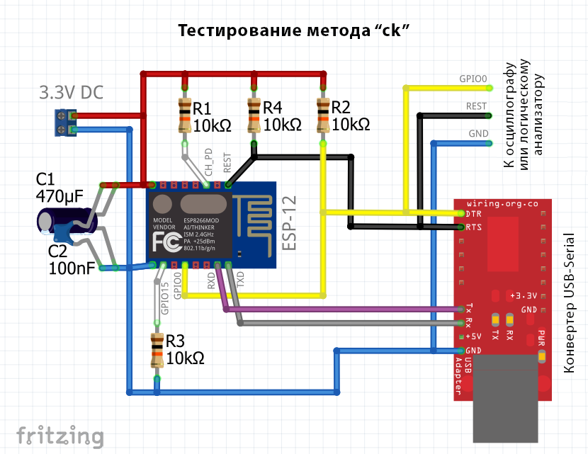
Простая цепь для проверки метода «ck»
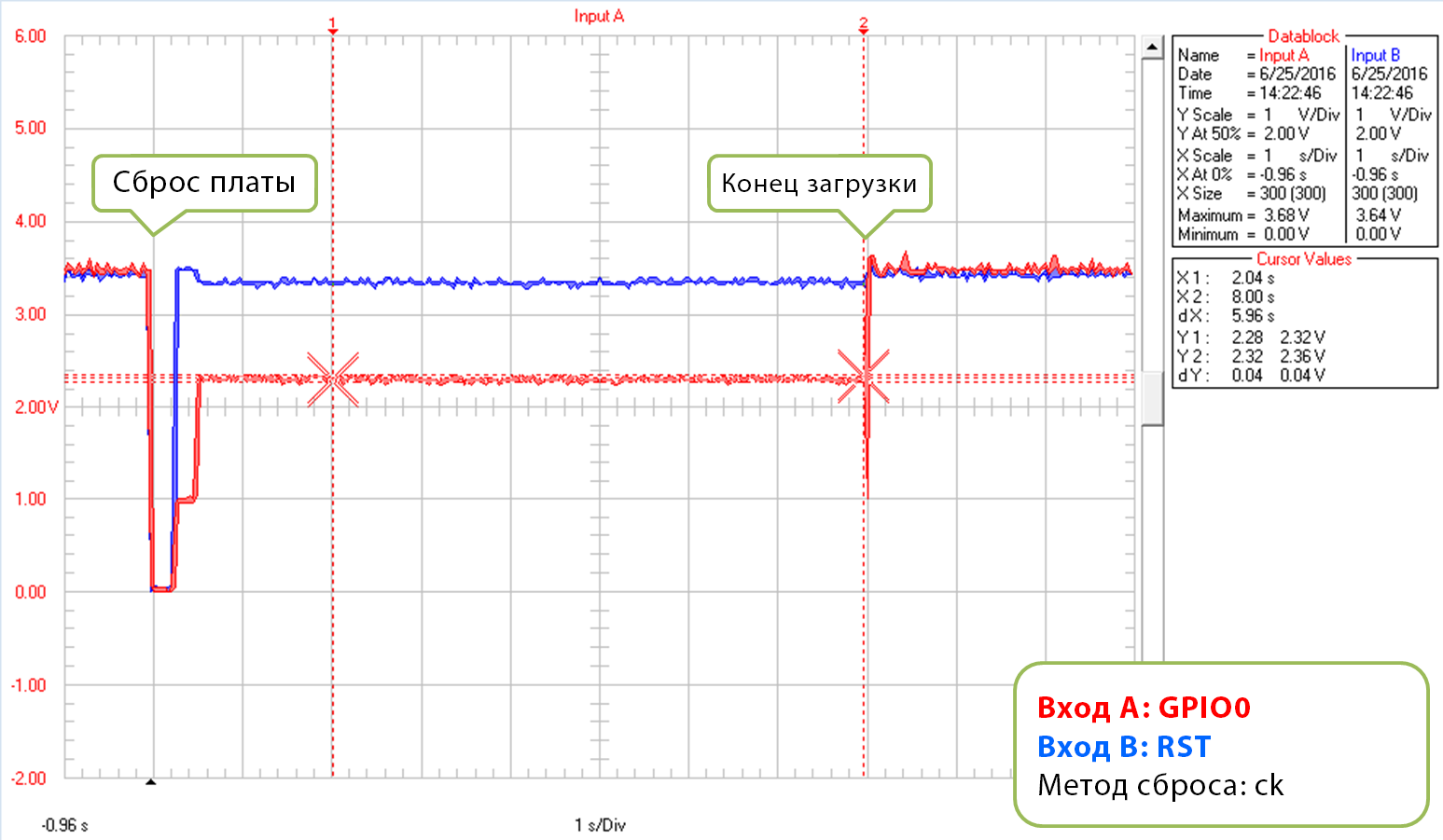
Графики ниже показывают сигналы напряжения на контактах GPIO0 и RST при загрузке прошивки.
Первый график показывает форму сигнала в начале загрузки кода.
Метод сброса «ck», начало загрузки кода
Второй график показывает полную загрузку скетча «Blink.io» на скорости 921600 бод. Это довольно высокая скорость, поэтому на загрузку уходит всего 8 секунд.
Метод сброса «ck», загрузка скетча «Blink.io»
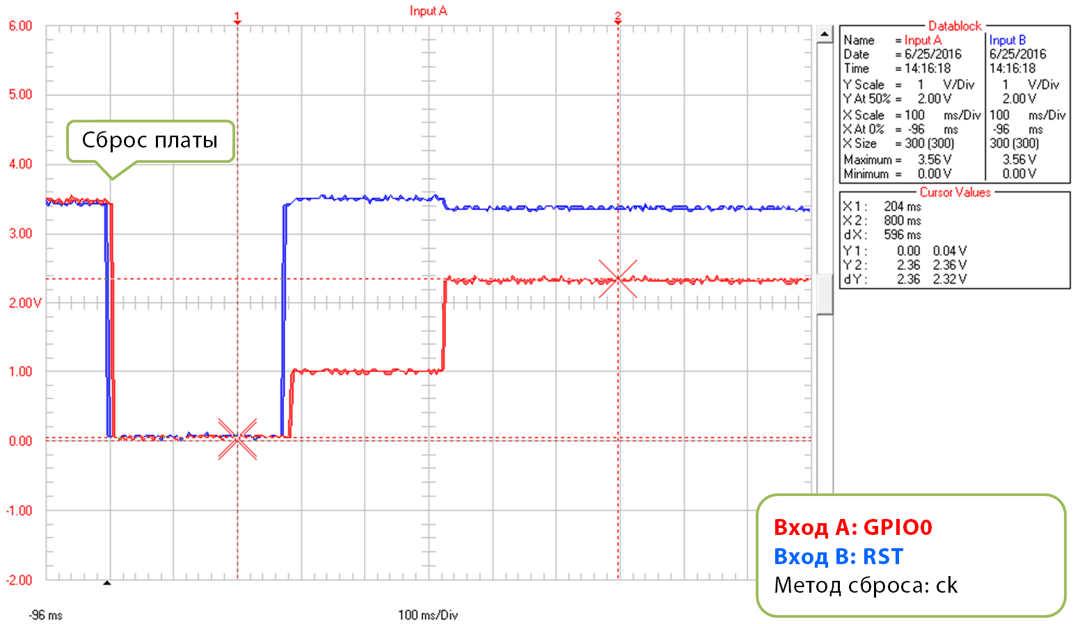
Когда у «esptool» не получается выполнить загрузку, он инициализирует сброс. Подобная ситуация показана, к примеру, на графике ниже.
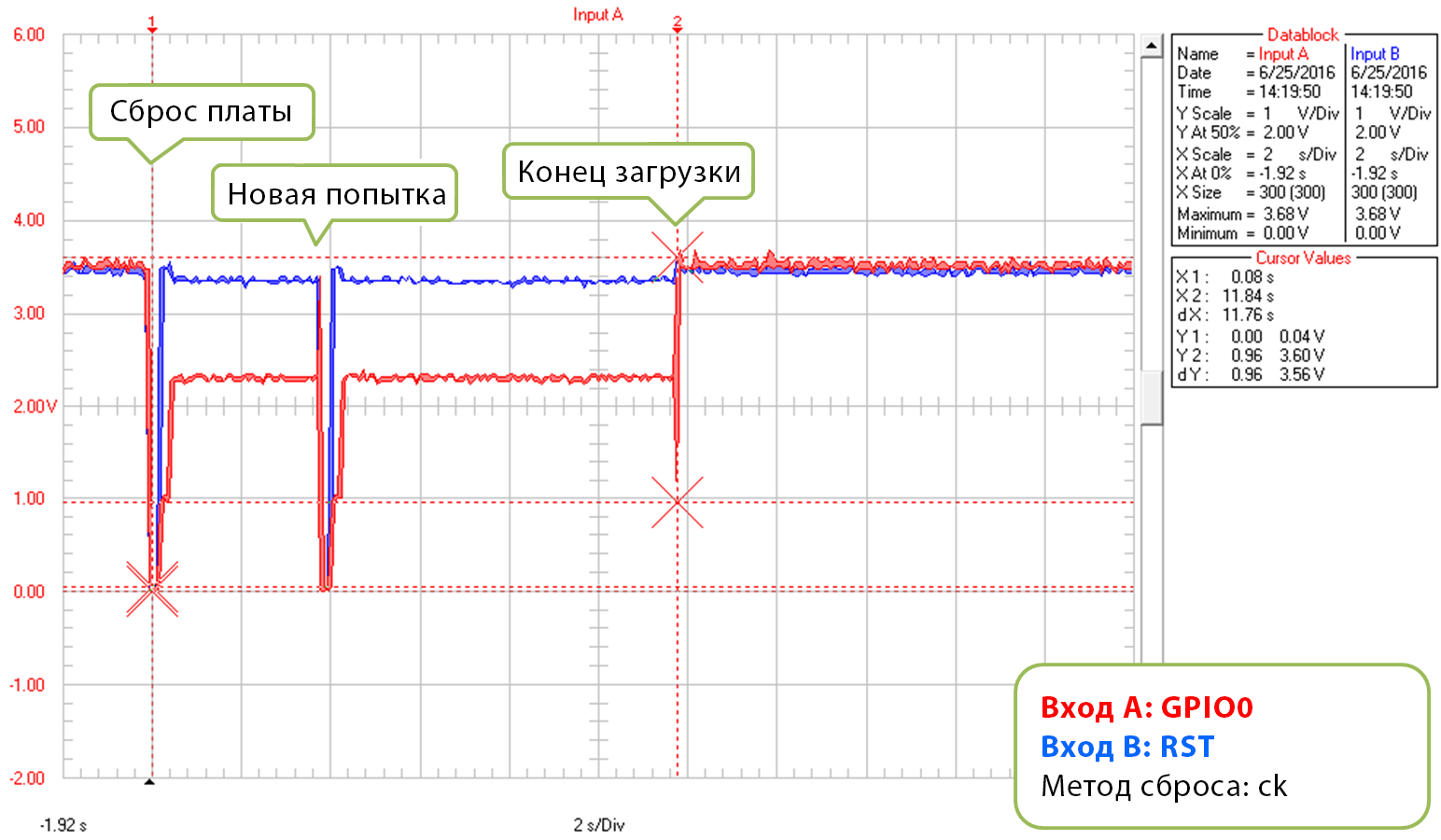
Метод сброса «ck», конец загрузки
Каждая новая попытка отображается в логах загрузки:
resetting board
trying to connect
    flush start
    setting serial port timeouts to 1 ms
    setting serial port timeouts to 1000 ms
    flush complete
    espcomm_send_command: sending command header
    espcomm_send_command: sending command payload
    read 0, requested 1
Цепь, показанная выше, имеет одно важное ограничение при работе с IDE Arduino. После открытия монитора порта ( Ctrl + ⇧ Shift + M ) линии RTS и DTR переключаются в состояние LOW. Поскольку линия RTS подключена к входной линии REST на ESP8266, то ESP8266 просто зависнет в состоянии сброса и запустить его будет нельзя. Следовательно, после загрузки прошивки вам нужно отключить обе линии или воспользоваться другой консолью (не монитором порта IDE Arduino), которая не переключает RTS и DTR в состояние LOW. В противном случае модуль зависнет в ожидании переключения REST в состояние HIGH и в мониторе порта ничего показывать не будет.
Что касается другой консоли, можно воспользоваться монитором порта IDE Arduino для ESP8266, разработанной пользователем mytrain и обсуждаемой в отчете 1360.
Если предпочитаете программы, то для Windows я бы порекомендовал бесплатную и удобную Termite.
Nodemcu
Метод сброса «nodemcu» получил название от платы NodeMCU, где он был реализован в самый первый раз. Этот метод позволяет обойти ограничения с управлением линиями RTS и DTR, о которых говорилось в главе о методе «ck».
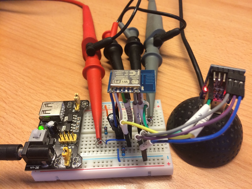
Ниже показана простая цепь для измерения формы сигнала при помощи метода «nodemcu»:
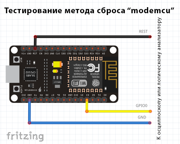
Простая цепь для проверки метода «nodemcu»
Первый график показывает напряжение на контактах GPIO0 и RST в начале загрузки прошивки:
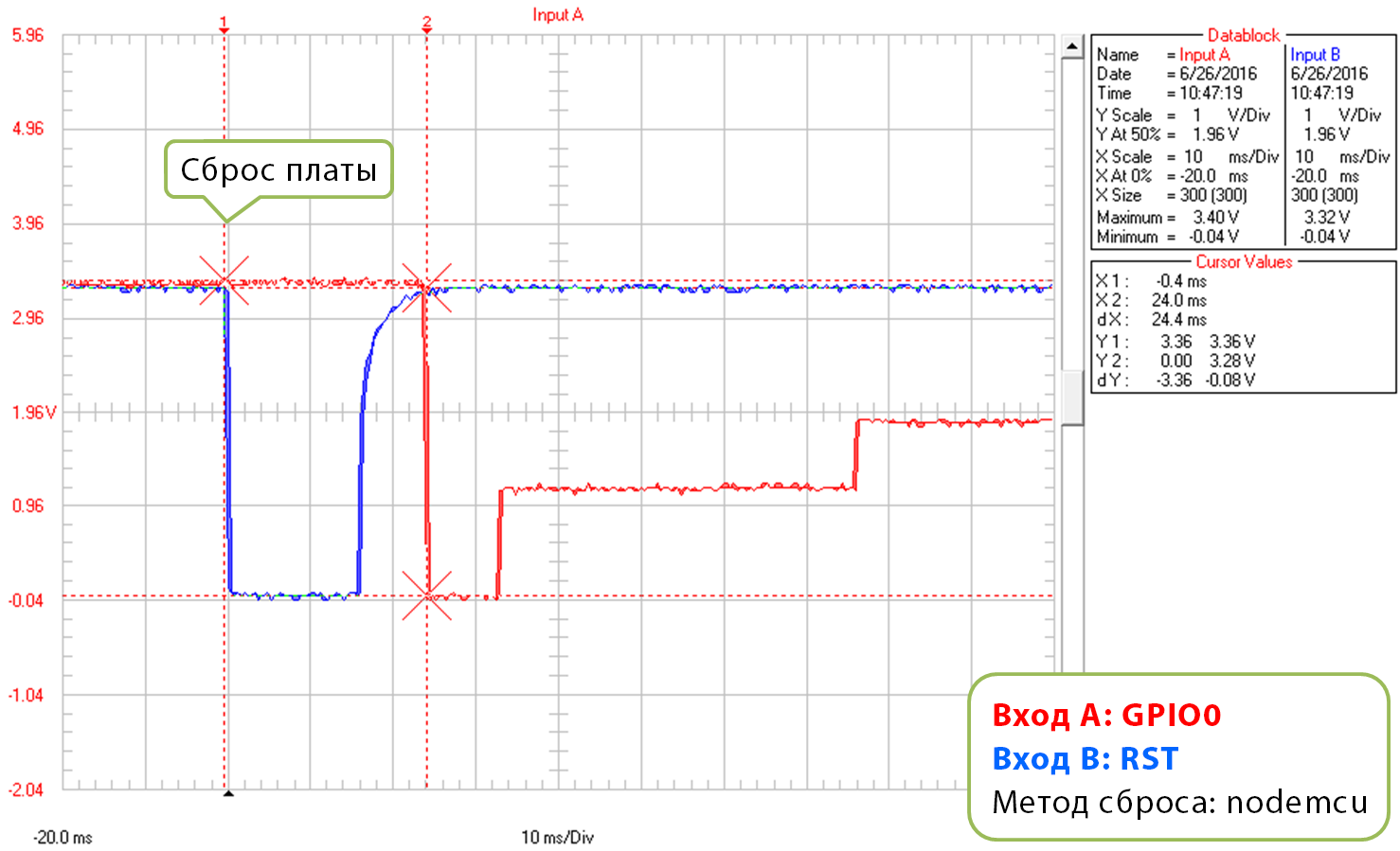
Метод сброса: «nodemcu», начало загрузки
Обратите внимание, что последовательность сигналов длится в 10 раз короче, чем при использовании метода «ck» – примерно 25 мс против 250 мс.
Второй график показывает загрузку скетча «Blink.ino» на скорости 921600 бод. Не считая разницы в длине последовательности сигналов, он выглядит как аналогичный график для метода «ck».
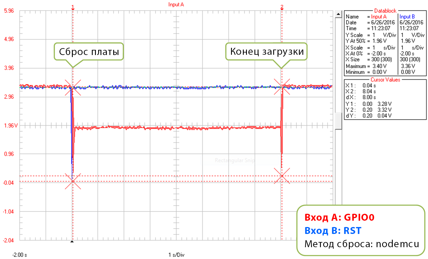
Метод сброса: «nodemcu», загрузка полностью
Третий график тоже демонстрирует загрузку скетча «Blink.ino» на скорости 921600 бод, но с двумя попытками сброса.
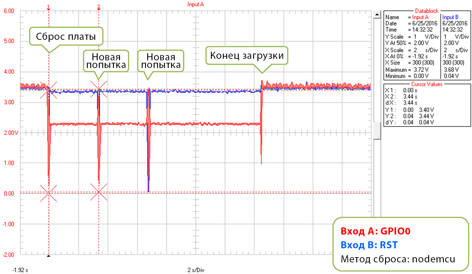
Метод сброса: «nodemcu», с двумя новыми попытками сброса
Если вам интересно, как реализуется этот метод сброса, обратите внимание на схемы ниже. Он не притягивает линии RTS и DTR к «земле», когда вы открываете в IDE Arduino монитор порта.
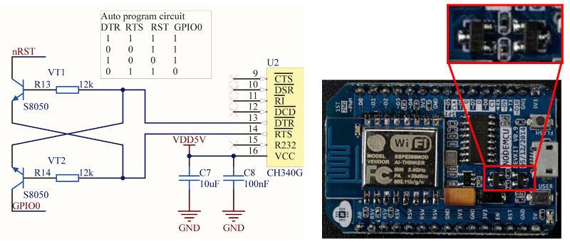
Реализация сброса методом «nodemcu»
Такая цепь состоит из двух транзисторов и резисторов, расположенных на плате NodeMCU. Слева изображены полная схема и таблица истинности – она показывает, как сигналы RTS и DTR на последовательном порту преобразуются в контакты RST и GPIO0 на ESP8266. Более подробно смотрите в репозитории NodeMCU на GitHub.
Эм… похоже, я застрял
Надеемся, советы выше помогли вам справиться с ошибкой «espcomm_sync failed», а загрузка прошивки на ESP8266 стала быстрой и беспроблемной.
Если опять нет, пробегитесь по вопросам ниже (они представляют короткую версию того, о чем писалось в главах выше):
Предварительные проверки
- Подключен ли ваш модуль к последовательному порту? Видит ли его IDE Arduino?
- Отвечает ли подключенный девайс на IDE Arduino? Какое именно сообщение появляется в отладочном окне?
- Правильный ли модуль ESP8266 выбран в меню «Плата»? Что именно у вас выбрано?
- Пробовали ли вы снизить скорость загрузки? Какую скорость вы уже попробовали?
Дополнительные проверки
- Какое сообщение присылает ESP8266 на скорости 74880 бод, когда вы входите в режим загрузчика?
- Проверяли ли вы конвертер USB-Serial, зациклив его? Каков был результат?
- Соответствует ли информация, показанная в логах, настройкам IDE Arduino? Если да, что в них?
Метод сброса
- Какой метод сброса вы используете?
- Какая у вас схема подключения? Она соответствует той, что показана в FAQ?
- Какую форму имеет сигнал во время сброса? Она соответствует форме сигнала в FAQ?
- Какую форму имеет сигнал при полной загрузке скетча? Она соответствует форме сигнала в FAQ?
ПО
- Вы используете стабильную версию аддона ESP8266 для IDE Arduino? Что это за версия?
- Как называется и какая версия у ваших IDE и ОС?
Если застопорились на каком-то шаге, опишите его как можно подробней и обратитесь за помощью на форум сообщества ESP8266.
Итого
С таким разнообразием модулей и плат на базе ESP8266, а также возможных методов сброса, решение проблем с загрузкой может потребовать очень много проб и попыток.
Если вы новичок, лучше использовать платы со встроенными USB-Serial конвертером и цепью для питания. Осторожно проверяйте сообщения в отладочном окне, а затем действуйте согласно этим сообщениям. Выберите правильный тип модуля в IDE Arduino и правильно настройте скорость загрузки прошивки. Проверьте, действительно ли плата переключена в режим загрузчика. Проверьте работоспособность USB-Serial конвертера, зациклив его. Проанализируйте детальные логи на предмет несоответствий с настройками IDE Arduino.
Проверьте схему подключения и форму сигнала на соответствие используемому методу сброса.
Если застряли, спросите совета у сообщества, предоставив данные обо всех выполненных вами шагах.
Тестовая площадка, которой я пользовался для проверки метода «ck»
На картинке выше показана тестовая площадка для метода «ck».
Во время подготовки этой статьи не пострадало ни одного ESP8266.
См.также
Внешние ссылки
- ↑ arduino-esp8266.readthedocs.io — I am getting “espcomm_sync failed” error when trying to upload my ESP. How to resolve this issue?
ESP8266 Руководство по устранению неисправностей
У ESP8266 есть несколько общих проблем, особенно при попытке записать новую прошивку или загрузке скриптов.
Вот подборка наиболее распространенных проблем с ESP8266 и способы для их исправления.
Устранение неполадок ESP8266 — NodeMCU Flasher
Где скачать флешер NodeMCU?
Перейдите в репозиторий GitHub флешера NodeMCU и загрузите флешер для вашей версии Windows, нажав кнопку «Raw»:
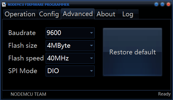
Какие настройки следует использовать с флешером NodeMCU?
Флешер NodeMCU уже поставляется с правильными настройками по умолчанию.
Настройки по умолчанию:
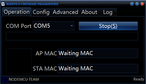
После нажатия кнопки «Flash» ничего не происходит, прошивальщик NodeMCU не запускает процесс перепрошивки
Если вы нажали кнопку «Flash» и ничего не происходит . Это может быть одно из двух:
- ESP не находится в режиме прошивки (перепроверьте, подключен ли GPIO 0 к GND при включении питания)
- программатор FTDI не может подать достаточный ток на ESP
Проблема 1 — Как заставить ESP перейти в режим прошивки:
- Закройте окно флешера NodeMCU
- Отключите питание от вашего ESP8266
- Подключите ESP следующим образом (дважды проверьте, что GPIO 0 подключен к GND)
- Подайте питание на ESP8266 и откройте флешер NodeMCU Нажмите кнопку «Flash»
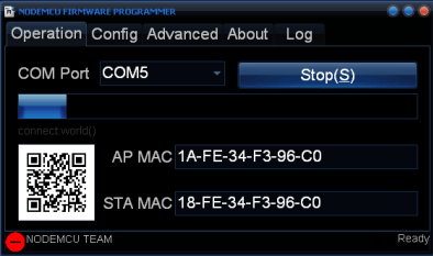
Если он все еще сообщает «Ожидание MAC», попробуйте следующее:
- Подключите провод от вашего reset ESP8266 к GND
- Отсоедините этот провод от GND и присоединитесь к VCC
Повторите шаги несколько раз, пока ESP не перезагрузится, и, скорее всего, флешер NodeMCU сможет обнаружить ESP и начать процесс перепрошивки.
Проблема 2. Если FTDI не может обеспечить достаточный ток, возможно, придется купить новый программатор FTDI или подключить ESP8266 к внешнему источнику питания.
Флешер NodeMCU зависает или останавливается на определенном проценте
- Отключите питание от ESP + FTDI: Закройте окно флешера NodeMCU
- Подключите ESP + FTDI к компьютеру снова
- Откройте флешер NodeMCU и попробуйте скорость передачи 19200 бод
Если этот процесс завершится неудачно, повторите ту же процедуру для следующих скоростей передачи (38400, 57600, 74880 и 115200).
Ппо крайней мере 5 человек столкнулись с той же проблемой, и этот способ решил ее.
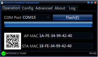
Как должен выглядеть NodeMCU после успешной прошивки?
У него должна быть зеленая стрелка внизу слева.
Разблокировка программатора FTDI на ПК с Windows
Если у вас новый программатор FTDI то сначала необходимо установить драйверы FTDI в Windows, посетите официальный веб-сайт для получения официальных драйверов: http://www.ftdichip.com/Drivers/VCP.htm.
В качестве альтернативы можете связаться с продавцом, который продал программатор FTDI.
Если возникли проблемы с установкой драйверов FTDI в Windows 7/8 / 8.1 / 10, вполне вероятно, что FTDI заблокирован.
Устранение неполадок ESP8266 — ESPlorer IDE
ESPlorer IDE Ошибка: разрешен только один tcp сервер
Это означает, что вы пытались загрузить несколько скриптов, и в ESP все еще выполняется старый скрипт с веб-сервером. Чтобы это исправить, нужно выполнить эти команды, чтобы удалить все файлы и перезапустить ESP:
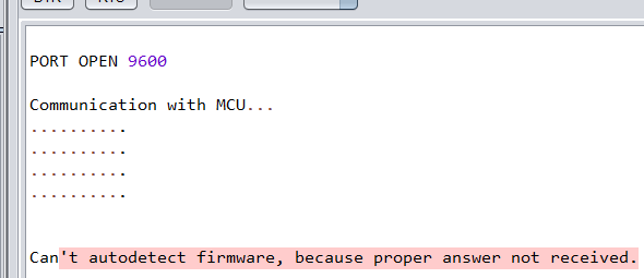
ESPlorer IDE Ошибка: не удается автоматически определить прошивку
ESPlorer IDE Ошибка: Ожидание ответа от ESP — истекло время ожидания. Команда прервана. Ожидание ответа от ESP — истекло время ожидания. Команда отменена.
Это означает что ESP, все еще находится в режиме прошивки. Как перевести ESP в режим пользователя:
- Закройте соединение ESPlorer IDE
- Отключите питание от ESP8266
- Подключите GPIO 0 к VCC
- Подайте питание на ESP8266 и восстановите соединение с ESPlorer IDE
Если он по-прежнему сообщает «не могу автоматически определить прошивку», попробуйте следующее:
- Подключите провод от вашего reset к GND
- Отключите этот провод от GND и присоедините к VCC
Код исчезает при перезапуске ESP8266
Если после загрузки скрипта в ESP ничего не происходит. Это означает, что ESP не смог найти скрипт или возникла проблема с памятью.
- Вы не сохранили свой скрипт под названием «init.lua». Повторная загрузка того же скрипта, но с именем «init.lua» должна решить проблему
- Это может быть проблема с памятью. Перепрошивка ESP с помощью прошивальщика NodeMCU обычно решает эту проблему.
Поиск IP-адреса ESP8266
Прежде чем начать, убедитесь, что вы проверили эти два пункта:
- Убедитесь, что скрипт, загруженный в ESP, имеет правильные сетевые учетные данные
- Убедитесь, что ESP находится рядом с маршрутизатором
Источник
Arduino.ru
Не могу добавить в менеджере плат IDE платы с ESP8266
- Войдите или зарегистрируйтесь, чтобы получить возможность отправлять комментарии
Здравствуйте! Не могу добавить платы на esp8266 в IDE. В настройках прописал http://arduino.esp8266.com/package_esp8266com_index.json но в менеджере плат с esp8266 нет. IDE выводит «произошла ошибка при загрузки http://arduino.esp8266.com/package_esp8266com_index.json». Может кто попробывать у кого как?
- Войдите или зарегистрируйтесь, чтобы получить возможность отправлять комментарии
- Войдите или зарегистрируйтесь, чтобы получить возможность отправлять комментарии

Сегодня ещё были проблемы с доменом arduino.esp8266.com, он не работал (иногда такое бывает). Поэтому в менеджере плат ESP8266 не появляется. Но уже починили.
- Войдите или зарегистрируйтесь, чтобы получить возможность отправлять комментарии

Да вот тут разработчики пишут что есть проблемы с DNS предлагают временно вставить такую строку
- Войдите или зарегистрируйтесь, чтобы получить возможность отправлять комментарии
по прежнему не грузится, кто как решил?
- Войдите или зарегистрируйтесь, чтобы получить возможность отправлять комментарии
Сейчас всё грузится.
- Войдите или зарегистрируйтесь, чтобы получить возможность отправлять комментарии
ага, спасибо, все заработало.
- Войдите или зарегистрируйтесь, чтобы получить возможность отправлять комментарии
Всем добра. Такая-же ерундовина как в первом посте
Вставлял рекомендованые ссылки ,никак , выдаёт ошибку :
версия ИДЕ 1.6.13
та-же ситуация и с ИДЕ 1.8.5
- Войдите или зарегистрируйтесь, чтобы получить возможность отправлять комментарии
Никак не установить плату ESP8266 — ошибка!
Ссылки в настройках по мануалу.
- Войдите или зарегистрируйтесь, чтобы получить возможность отправлять комментарии

Ошибки где? При установке поставьте галочку подробный вывод лога, в нем увидите пути где не хватает файлов, вручную кладёте и будет ок. Я сам нарвался месяц назад, а пару недель назад тут на форуме описывали — поищите.
- Войдите или зарегистрируйтесь, чтобы получить возможность отправлять комментарии
Включаю менеджер плат, нахожу «esp8266 by ESP8266 Community», нажимаю «установка» и:
Где галочку ставить?
Куда и что вручную класть?
Помогите чайнику, плз!
- Войдите или зарегистрируйтесь, чтобы получить возможность отправлять комментарии

Всегда, так уж вышло, добавлял без менеджера плат, просто клонировал по правилам в директорию hardware, как для esp8266 так и для esp32 (тиньки и stm32duino аналогично) и проблем не испытывал.
- Войдите или зарегистрируйтесь, чтобы получить возможность отправлять комментарии
В настройках ide есть галочка подробный вывод, после этого ещё раз попробуйте и внимательно почитайте ошибки, тогда будет понятно в чем дело
- Войдите или зарегистрируйтесь, чтобы получить возможность отправлять комментарии
Да, вылезло много букв, но понятно не стало.
Источник
Комментарии
Corsair
In file included from C:UsersCorsairDesktopGyverLamp-masterfirmwareGyverLamp_v1.5.5GyverLamp_v1.5.5.ino:97:0:
C:Program Files (x86)ArduinolibrariesFastLED-3.2.9/FastLED.h:14:21: note: #pragma message: FastLED version 3.002.009
# pragma message «FastLED version 3.002.009»
In file included from C:Program Files (x86)ArduinolibrariesFastLED-3.2.9/FastLED.h:65:0,
C:Program Files (x86)ArduinolibrariesFastLED-3.2.9/fastspi.h:115:23: note: #pragma message: No hardware SPI pins defined. All SPI access will default to bitbanged output
# pragma message «No hardware SPI pins defined. All SPI access will default to bitbanged output»
Скетч использует 329632 байт (31%) памяти устройства. Всего доступно 1044464 байт.
Глобальные переменные используют 43748 байт (53%) динамической памяти, оставляя 38172 байт для локальных переменных. Максимум: 81920 байт.
esptool.py v2.6
2.6
esptool.py v2.6
Serial port COM7
Connecting.
Chip is ESP8266EX
Features: WiFi
MAC: 50:02:91:67:de:0f
Uploading stub.
Running stub.
Stub running.
Changing baud rate to 460800
Changed.
Configuring flash size.
Auto-detected Flash size: 4MB
Compressed 333792 bytes to 237492.
Writing at 0x00000000. (6 %)
Writing at 0x00004000. (13 %)
Writing at 0x00008000. (20 %)
Writing at 0x0000c000. (26 %)
Writing at 0x00010000. (33 %)
Writing at 0x00014000. (40 %)
Writing at 0x00018000. (46 %)
Writing at 0x0001c000. (53 %)
Writing at 0x00020000. (60 %)
Writing at 0x00024000. (66 %)
Writing at 0x00028000. (73 %)
Writing at 0x0002c000. (80 %)
Writing at 0x00030000. (86 %)
Writing at 0x00034000. (93 %)
Writing at 0x00038000. (100 %)
Wrote 333792 bytes (237492 compressed) at 0x00000000 in 5.4 seconds (effective 498.7 kbit/s).
Hash of data verified.
Leaving.
Hard resetting via RTS pin.

Старик Похабыч
Kostefan
Привет товарищ я нашел причину. на матрице спаял зеленые провода, а этого делать не надо было
DaniilKend
Arduino: 1.8.9 (Windows Store 1.8.21.0) (Windows 10), Плата:»LOLIN(WEMOS) D1 R2 & mini, 80 MHz, Flash, Disabled, 4M (1M SPIFFS), v2 Higher Bandwidth, Disabled, None, Only Sketch, 921600″
In file included from E:АрдуиноGyverLamp-masterfirmwareGyverLamp_v1.1GyverLamp_v1.1.ino:65:0:
C:Users�������DocumentsArduinolibrariesFastLED/FastLED.h:14:21: note: #pragma message: FastLED version 3.003.002
# pragma message «FastLED version 3.003.002»
In file included from C:Users�������DocumentsArduinolibrariesFastLED/FastLED.h:65:0,
C:Users�������DocumentsArduinolibrariesFastLED/fastspi.h:130:23: note: #pragma message: No hardware SPI pins defined. All SPI access will default to bitbanged output
# pragma message «No hardware SPI pins defined. All SPI access will default to bitbanged output»
Скетч использует 324572 байт (31%) памяти устройства. Всего доступно 1044464 байт.
Глобальные переменные используют 43072 байт (52%) динамической памяти, оставляя 38848 байт для локальных переменных. Максимум: 81920 байт.
error: failed sending 0xC0
error: failed sending 8 bytes
error: failed sending 36 bytes
error: failed sending 0xC0
error: failed sending 0xC0
error: failed sending 8 bytes
error: failed sending 36 bytes
error: failed sending 0xC0
error: failed sending 0xC0
error: failed sending 8 bytes
error: failed sending 36 bytes
error: failed sending 0xC0
error: failed sending 0xC0
error: failed sending 8 bytes
error: failed sending 36 bytes
error: failed sending 0xC0
error: failed sending 0xC0
error: failed sending 8 bytes
error: failed sending 36 bytes
error: failed sending 0xC0
error: failed sending 0xC0
error: failed sending 8 bytes
error: failed sending 36 bytes
error: failed sending 0xC0
error: failed sending 0xC0
error: failed sending 8 bytes
error: failed sending 36 bytes
error: failed sending 0xC0
error: failed sending 0xC0
error: failed sending 8 bytes
error: failed sending 36 bytes
error: failed sending 0xC0
error: failed sending 0xC0
error: failed sending 8 bytes
error: failed sending 36 bytes
error: failed sending 0xC0
warning: espcomm_sync failed
error: espcomm_open failed
error: espcomm_upload_mem failed
error: espcomm_upload_mem failed
Этот отчёт будет иметь больше информации с
включенной опцией Файл -> Настройки ->
«Показать подробный вывод во время компиляции»
Помогите не знаю что не так сижу уже 1.5 дней
Источник
Комментарии

Brighton
Arduino: 1.8.10 (Windows 7), Плата:»LOLIN(WEMOS) D1 R2 & mini, 80 MHz, Flash, Disabled, All SSL ciphers (most compatible), 4M (no SPIFFS), v2 Lower Memory, Disabled, None, Only Sketch, 921600″
In file included from C:UsersAydarDesktopGyverLamp-masterfirmwareGyverLamp_v1.5.5GyverLamp_v1.5.5.ino:97:0:
C:Program Files (x86)ArduinolibrariesFastLED-3.2.9/FastLED.h:14:21: note: #pragma message: FastLED version 3.002.009
# pragma message «FastLED version 3.002.009»
In file included from C:Program Files (x86)ArduinolibrariesFastLED-3.2.9/FastLED.h:65:0,
C:Program Files (x86)ArduinolibrariesFastLED-3.2.9/fastspi.h:115:23: note: #pragma message: No hardware SPI pins defined. All SPI access will default to bitbanged output
# pragma message «No hardware SPI pins defined. All SPI access will default to bitbanged output»
Скетч использует 329616 байт (31%) памяти устройства. Всего доступно 1044464 байт.
Глобальные переменные используют 43748 байт (53%) динамической памяти, оставляя 38172 байт для локальных переменных. Максимум: 81920 байт.
esptool.py v2.6
2.6
esptool.py v2.6
Serial port COM3
Connecting. _____. _____. _____. _____. _____. _____. ____Traceback (most recent call last):
File «C:UsersAydarAppDataLocalArduino15packagesesp8266hardwareesp82662.5.2/tools/upload.py», line 25, in
esptool.main(fakeargs)
File «C:/Users/Aydar/AppData/Local/Arduino15/packages/esp8266/hardware/esp8266/2.5.2/tools/esptoolesptool.py», line 2653, in main
esp.connect(args.before)
File «C:/Users/Aydar/AppData/Local/Arduino15/packages/esp8266/hardware/esp8266/2.5.2/tools/esptoolesptool.py», line 468, in connect
raise FatalError(‘Failed to connect to %s: %s’ % (self.CHIP_NAME, last_error))
esptool.FatalError: Failed to connect to ESP8266: Timed out waiting for packet header
esptool.FatalError: Failed to connect to ESP8266: Timed out waiting for packet header
Этот отчёт будет иметь больше информации с
включенной опцией Файл -> Настройки ->
«Показать подробный вывод во время компиляции»
Кто-нибудь знает в чём ошибка? Сколько раз перепробовал, не получается

awiscan
Arduino: 1.8.10 (Windows 7), Плата:»LOLIN(WEMOS) D1 R2 & mini, 80 MHz, Flash, Disabled, All SSL ciphers (most compatible), 4M (no SPIFFS), v2 Lower Memory, Disabled, None, Only Sketch, 921600″
In file included from C:UsersAydarDesktopGyverLamp-masterfirmwareGyverLamp_v1.5.5GyverLamp_v1.5.5.ino:97:0:
C:Program Files (x86)ArduinolibrariesFastLED-3.2.9/FastLED.h:14:21: note: #pragma message: FastLED version 3.002.009
# pragma message «FastLED version 3.002.009»
In file included from C:Program Files (x86)ArduinolibrariesFastLED-3.2.9/FastLED.h:65:0,
C:Program Files (x86)ArduinolibrariesFastLED-3.2.9/fastspi.h:115:23: note: #pragma message: No hardware SPI pins defined. All SPI access will default to bitbanged output
# pragma message «No hardware SPI pins defined. All SPI access will default to bitbanged output»
Скетч использует 329616 байт (31%) памяти устройства. Всего доступно 1044464 байт.
Глобальные переменные используют 43748 байт (53%) динамической памяти, оставляя 38172 байт для локальных переменных. Максимум: 81920 байт.
esptool.py v2.6
2.6
esptool.py v2.6
Serial port COM3
Connecting. _____. _____. _____. _____. _____. _____. ____Traceback (most recent call last):
File «C:UsersAydarAppDataLocalArduino15packagesesp8266hardwareesp82662.5.2/tools/upload.py», line 25, in
esptool.main(fakeargs)
File «C:/Users/Aydar/AppData/Local/Arduino15/packages/esp8266/hardware/esp8266/2.5.2/tools/esptoolesptool.py», line 2653, in main
esp.connect(args.before)
File «C:/Users/Aydar/AppData/Local/Arduino15/packages/esp8266/hardware/esp8266/2.5.2/tools/esptoolesptool.py», line 468, in connect
raise FatalError(‘Failed to connect to %s: %s’ % (self.CHIP_NAME, last_error))
esptool.FatalError: Failed to connect to ESP8266: Timed out waiting for packet header
esptool.FatalError: Failed to connect to ESP8266: Timed out waiting for packet header
Этот отчёт будет иметь больше информации с
включенной опцией Файл -> Настройки ->
«Показать подробный вывод во время компиляции»
Кто-нибудь знает в чём ошибка? Сколько раз перепробовал, не получается
Источник
| title |
|---|
|
Frequently Asked Questions / Troubleshooting |
FAQ list 🔙
I am getting «espcomm_sync failed» error when trying to upload my ESP. How to resolve this issue?
- Introduction
- Initial Checks
- Advanced Checks
- Reset Methods
- Ck
- Nodemcu
- I’m Stuck
- Conclusion
Introduction
This message indicates issue with uploading ESP module over a serial connection. There are couple of possible causes, that depend on the type of module, if you use separate USB to serial converter, what parameters are selected for upload, etc. As result there is no single answer on the root cause. To find it out you may need to complete couple of troubleshooting steps.
Note: If you are just starting with ESP, to reduce potential issues with uploading, select ESP board with integrated USB to serial converter. This will considerably reduce number of user depended factors or configuration settings that influence upload process.
Example boards with USB to serial converter build in, that will make your initial project development easier, are shown below.

If you are using a Generic ESP8266 module, separate USB to serial converter and connect them by yourself, please make sure you have the following three things right:
- Module is provided with enough power,
- GPIO0, GPIO15 and CH_PD are connected using pull up / pull down resistors,
- Module is put into boot loader mode.
For specific details please refer to section on Generic ESP8266 modules. Example modules without USB to serial converter on board are shown below.

Initial Checks
In order to troubleshoot «espcomm_sync failed» error, please proceed step by step through the checklist below. This list is organized starting with most common and simple to more complex issues.
- Start with reading exact message displayed in debug window of Arduino IDE. In many cases it provides direct information where the issue is.

For instance message above suggests that Arduino IDE is unable to open a serial port COM3. Check if you have selected port where your module is connected to.

- If a module is connected to the serial port but not responding as a valid ESP8266 device, the message will read slightly different (see below). If you have other modules connected to your PC, make sure that you are uploading code to ESP8266 and not to e.g. Arduino UNO.

- To have your PC talking to ESP, select exact ESP type in upload menu. If selection is incorrect then the upload may fail.

Basing on selected board type, Arduino IDE will apply specific «reset method» to enter the board into boot loading mode. Reset methods are board specific. Some boards do not have the h/w in place to support reset by Arduino IDE. If this is the case, you need to enter such board into boot loading mode manually.
- Upload may be also failing due to too high speed. If you have long or poor quality USB cable, try reducing selection under Upload Speed.

Advanced Checks
- If you are still facing issues, test if module is indeed entering the boot loading mode. You can do it by connecting secondary USB to serial converter and checking the message displayed. Attach RX and GND pins of converter to TX and GND pin of ESP as shown on example below (get fzz source).

Then open a terminal at 74880 baud, and look what message is reported when ESP is being reset for programming. Correct message looks as follows:
ets Jan 8 2013,rst cause:2, boot mode:(1,7)
If you see similar message but different values then decode them using Boot Messages and Modes. The key information is contained in first digit / three right-most bits of the boot mode message as shown below.

For instance message boot mode (3,3) indicates that pins GPIO2 and GPIO0 are set HIGH and GPIO15 is set LOW. This is configuration for normal operation of module (to execute application from flash), not for boot loading (flash programming).
Note: Without having this step right you will not be able to upload your module over a serial port.
- You have confirmed that module is in boot loading mode but upload still fails. If you are using external USB to serial converter, then check if it operates correctly by looping it back. This is quite simple check. Just connect TX and RX of your converter together like on picture below. Then open Serial Monitor and type some characters. If everything is fine, then you should see what you type immediately printed back on the monitor. For an ESP with USB to serial converter on board, this check may involve breaking some PCB traces. I would not do it unless being desperate. Instead try steps below.

- Next step to try, if not done already, is checking detailed debug messages. Go to File > Preferences, enable Show verbose output during: upload and try uploading again. For successful upload this log should look similar to example shown below:
C:UsersKrzysztofAppDataLocalArduino15packagesesp8266toolsesptool.4.8/esptool.exe -vv -cd ck -cb 115200 -cp COM3 -ca 0x00000 -cf C:UsersKRZYSZ~1AppDataLocalTempbuild7e44b372385012e74d64fb272d24b802.tmp/Blink.ino.bin
esptool v0.4.8 - (c) 2014 Ch. Klippel <ck@atelier-klippel.de>
    setting board to ck
    setting baudrate from 115200 to 115200
    setting port from COM1 to COM3
    setting address from 0x00000000 to 0x00000000
    espcomm_upload_file
    espcomm_upload_mem
    setting serial port timeouts to 1000 ms
opening bootloader
resetting board
trying to connect
    flush start
    setting serial port timeouts to 1 ms
    setting serial port timeouts to 1000 ms
    flush complete
    espcomm_send_command: sending command header
    espcomm_send_command: sending command payload
    read 0, requested 1
trying to connect
    flush start
    setting serial port timeouts to 1 ms
    setting serial port timeouts to 1000 ms
    flush complete
    espcomm_send_command: sending command header
    espcomm_send_command: sending command payload
    espcomm_send_command: receiving 2 bytes of data
    espcomm_send_command: receiving 2 bytes of data
    espcomm_send_command: receiving 2 bytes of data
    espcomm_send_command: receiving 2 bytes of data
    espcomm_send_command: receiving 2 bytes of data
    espcomm_send_command: receiving 2 bytes of data
    espcomm_send_command: receiving 2 bytes of data
    espcomm_send_command: receiving 2 bytes of data
Uploading 226368 bytes from to flash at 0x00000000
    erasing flash
    size: 037440 address: 000000
    first_sector_index: 0
    total_sector_count: 56
    head_sector_count: 16
    adjusted_sector_count: 40
    erase_size: 028000
    espcomm_send_command: sending command header
    espcomm_send_command: sending command payload
    setting serial port timeouts to 15000 ms
    setting serial port timeouts to 1000 ms
    espcomm_send_command: receiving 2 bytes of data
    writing flash
..............................................................................................................................................................................................................................
starting app without reboot
    espcomm_send_command: sending command header
    espcomm_send_command: sending command payload
    espcomm_send_command: receiving 2 bytes of data
closing bootloader
    flush start
    setting serial port timeouts to 1 ms
    setting serial port timeouts to 1000 ms
    flush complete
Upload log may be longer depending on number of connection attempts made by esptool. Analyze it for any anomalies to configuration you have selected in Arduino IDE, like different serial port, reset method, baud rate, etc. Resolve all noted differences.
Reset Methods
If you got to this point and still see espcomm_sync failed, then now you need to bring in the heavy guns.
Connect scope or logic analyzer to GPIO0, RST and RXD pins of the ESP to check what’s happening.
Then compare your measurements with wave-forms collected for circuits below. They document two standard methods of resetting ESP8266 for upload, that you can select in Arduino IDE — ck and nodemcu.
Ck
Circuit below has been prepared to collect wave-forms for ck reset method (get fzz source). It is simpler than for nodemcu reset and therefore often used to wire up generic ESP modules on a breadboard. Check it against your wiring when comparing your measurements against wave-forms below.

The following wave-forms below show voltage signals on GPIO0 and RST pins of the ESP board when uploading the firmware.
Close up of ck reset method signal sequence at the beginning of upload is shown below.

Next picture shows complete upload of Blink.ino example at 921600 baud. This is quite high speed, so the upload takes only about 8s.

Please note that when esptool is not able to initialize upload at the first time, then it retries reset procedure. Case of one such retry is shown on wave-form below.

Each retry is reported in upload log as follows:
resetting board
trying to connect
    flush start
    setting serial port timeouts to 1 ms
    setting serial port timeouts to 1000 ms
    flush complete
    espcomm_send_command: sending command header
    espcomm_send_command: sending command payload
    read 0, requested 1
Presented circuit has one important limitation when it comes to work with Arduino IDE. After opening Serial Monitor (Ctrl-Shift-M), both RTS and DTR lines are permanently pulled down. As RTS line is connected to REST input of ESP, the module is hold in reset state / not able to run. Therefore after uploading module, you need to disconnect both lines or use different serial terminal program that is not pulling down RTS and DTR lines. Otherwise the module will get stuck waiting for releasing the REST signal and you will see nothing on the Serial Monitor.
As for different serial terminal program you can check Arduino IDE add-on Serial Monitor for ESP8266 developed by user @mytrain and discussed in #1360.
If you prefer external terminal program, then for Windows users we can recommend free and handy Termite.
Nodemcu
Nodemcu reset method is named after NodeMCU board where it has been introduced for the first time. It overcomes limitations with handling of RTS and DTR lines discussed for ck reset method above.
Sample circuit to measure wave-form is shown below (get fzz source).

Close up of voltage signals on GPIO0 and RST pins at the beginning of firmware upload is shown below.

Please note that the reset sequence is about 10x shorter comparing to ck reset (about 25ms vs. 250ms).
Next picture covers complete upload of Blink.ino example at 921600 baud. Except for difference of the reset signal sequence, the complete upload looks similar to that of ck.

A sample wave-form below shows another upload of Blink.ino example at 921600 baud, but with two reset retries.

If you are interested how noodemcu reset method is implemented, then check circuit below. As indicated it does not pull to ground RTS and DTR lines once you open Serial Monitor in Arduino IDE.

It consists of two transistors and resistors that you can locate on NodeMCU board on right. On left you can see complete circuit and the truth table how RTS and DTR signals of the serial interface are translated to RST and GPIO0 on the ESP. For more details please refer to nodemcu repository on GitHub.
I’m Stuck
Hopefully at this point you were able to resolve espcomm_sync failed issue and now enjoy quick and reliable uploads of your ESP modules.
If this is still not the case, then review once more all discussed steps in the checklist below.
Initial Checks
- Is your module connected to serial port and visible in IDE?
- Is connected device responding to IDE? What is exact message in debug window?
- Have you selected correct ESP module type in Board menu? What is the selection?
- Have you tried to reduce upload speed? What speeds have you tried?
Advanced Checks
- What message is reported by ESP at 74880 baud when entering boot loading mode?
- Have you checked your USB to serial converter by looping it back? What is the result?
- Is your detailed upload log consistent with settings in IDE? What is the log?
Reset Method
- What reset method do you use?
- What is your connection diagram? Does it match diagram in this FAQ?
- What is your wave-form of board reset? Does it match wave-form in this FAQ?
- What is your wave-form of complete upload? Does it match wave-form in this FAQ?
Software
- Do you use the latest stable version of esp8266 / Arduino? What is it?
- What is the name and version of your IDE and O/S?
If you are stuck at certain step, then post this list on ESP8266 Community Forum asking for support.
Conclusion
With variety of available ESP8266 modules and boards, as well as possible connection methods, troubleshooting of upload issues may take several steps.
If you are a beginner, then use boards with integrated power supply and USB to serial converter. Check carefully message in debug window and act accordingly. Select your exact module type in IDE and try to adjust upload speed. Check if board is indeed entering boot loading mode. Check operation of your USB to serial converter with loop back. Analyze detailed upload log for inconsistencies with IDE settings.
Verify your connection diagram and wave-form for consistency with selected reset method.
If you get stuck, then ask community for support providing summary of all completed checks.

Test stand used for checking of ck reset method is shown above.
No any ESP module has been harmed during preparation of this FAQ item.
FAQ list 🔙
| title |
|---|
|
Frequently Asked Questions / Troubleshooting |
FAQ list 🔙
I am getting «espcomm_sync failed» error when trying to upload my ESP. How to resolve this issue?
- Introduction
- Initial Checks
- Advanced Checks
- Reset Methods
- Ck
- Nodemcu
- I’m Stuck
- Conclusion
Introduction
This message indicates issue with uploading ESP module over a serial connection. There are couple of possible causes, that depend on the type of module, if you use separate USB to serial converter, what parameters are selected for upload, etc. As result there is no single answer on the root cause. To find it out you may need to complete couple of troubleshooting steps.
Note: If you are just starting with ESP, to reduce potential issues with uploading, select ESP board with integrated USB to serial converter. This will considerably reduce number of user depended factors or configuration settings that influence upload process.
Example boards with USB to serial converter build in, that will make your initial project development easier, are shown below.
If you are using a Generic ESP8266 module, separate USB to serial converter and connect them by yourself, please make sure you have the following three things right:
- Module is provided with enough power,
- GPIO0, GPIO15 and CH_PD are connected using pull up / pull down resistors,
- Module is put into boot loader mode.
For specific details please refer to section on Generic ESP8266 modules. Example modules without USB to serial converter on board are shown below.
Initial Checks
In order to troubleshoot «espcomm_sync failed» error, please proceed step by step through the checklist below. This list is organized starting with most common and simple to more complex issues.
- Start with reading exact message displayed in debug window of Arduino IDE. In many cases it provides direct information where the issue is.
For instance message above suggests that Arduino IDE is unable to open a serial port COM3. Check if you have selected port where your module is connected to.
- If a module is connected to the serial port but not responding as a valid ESP8266 device, the message will read slightly different (see below). If you have other modules connected to your PC, make sure that you are uploading code to ESP8266 and not to e.g. Arduino UNO.
- To have your PC talking to ESP, select exact ESP type in upload menu. If selection is incorrect then the upload may fail.
Basing on selected board type, Arduino IDE will apply specific «reset method» to enter the board into boot loading mode. Reset methods are board specific. Some boards do not have the h/w in place to support reset by Arduino IDE. If this is the case, you need to enter such board into boot loading mode manually.
- Upload may be also failing due to too high speed. If you have long or poor quality USB cable, try reducing selection under Upload Speed.
Advanced Checks
- If you are still facing issues, test if module is indeed entering the boot loading mode. You can do it by connecting secondary USB to serial converter and checking the message displayed. Attach RX and GND pins of converter to TX and GND pin of ESP as shown on example below (get fzz source).
Then open a terminal at 74880 baud, and look what message is reported when ESP is being reset for programming. Correct message looks as follows:
ets Jan 8 2013,rst cause:2, boot mode:(1,7)
If you see similar message but different values then decode them using Boot Messages and Modes. The key information is contained in first digit / three right-most bits of the boot mode message as shown below.
For instance message boot mode (3,3) indicates that pins GPIO2 and GPIO0 are set HIGH and GPIO15 is set LOW. This is configuration for normal operation of module (to execute application from flash), not for boot loading (flash programming).
Note: Without having this step right you will not be able to upload your module over a serial port.
- You have confirmed that module is in boot loading mode but upload still fails. If you are using external USB to serial converter, then check if it operates correctly by looping it back. This is quite simple check. Just connect TX and RX of your converter together like on picture below. Then open Serial Monitor and type some characters. If everything is fine, then you should see what you type immediately printed back on the monitor. For an ESP with USB to serial converter on board, this check may involve breaking some PCB traces. I would not do it unless being desperate. Instead try steps below.
- Next step to try, if not done already, is checking detailed debug messages. Go to File > Preferences, enable Show verbose output during: upload and try uploading again. For successful upload this log should look similar to example shown below:
C:UsersKrzysztofAppDataLocalArduino15packagesesp8266toolsesptool.4.8/esptool.exe -vv -cd ck -cb 115200 -cp COM3 -ca 0x00000 -cf C:UsersKRZYSZ~1AppDataLocalTempbuild7e44b372385012e74d64fb272d24b802.tmp/Blink.ino.bin
esptool v0.4.8 - (c) 2014 Ch. Klippel <ck@atelier-klippel.de>
    setting board to ck
    setting baudrate from 115200 to 115200
    setting port from COM1 to COM3
    setting address from 0x00000000 to 0x00000000
    espcomm_upload_file
    espcomm_upload_mem
    setting serial port timeouts to 1000 ms
opening bootloader
resetting board
trying to connect
    flush start
    setting serial port timeouts to 1 ms
    setting serial port timeouts to 1000 ms
    flush complete
    espcomm_send_command: sending command header
    espcomm_send_command: sending command payload
    read 0, requested 1
trying to connect
    flush start
    setting serial port timeouts to 1 ms
    setting serial port timeouts to 1000 ms
    flush complete
    espcomm_send_command: sending command header
    espcomm_send_command: sending command payload
    espcomm_send_command: receiving 2 bytes of data
    espcomm_send_command: receiving 2 bytes of data
    espcomm_send_command: receiving 2 bytes of data
    espcomm_send_command: receiving 2 bytes of data
    espcomm_send_command: receiving 2 bytes of data
    espcomm_send_command: receiving 2 bytes of data
    espcomm_send_command: receiving 2 bytes of data
    espcomm_send_command: receiving 2 bytes of data
Uploading 226368 bytes from to flash at 0x00000000
    erasing flash
    size: 037440 address: 000000
    first_sector_index: 0
    total_sector_count: 56
    head_sector_count: 16
    adjusted_sector_count: 40
    erase_size: 028000
    espcomm_send_command: sending command header
    espcomm_send_command: sending command payload
    setting serial port timeouts to 15000 ms
    setting serial port timeouts to 1000 ms
    espcomm_send_command: receiving 2 bytes of data
    writing flash
..............................................................................................................................................................................................................................
starting app without reboot
    espcomm_send_command: sending command header
    espcomm_send_command: sending command payload
    espcomm_send_command: receiving 2 bytes of data
closing bootloader
    flush start
    setting serial port timeouts to 1 ms
    setting serial port timeouts to 1000 ms
    flush complete
Upload log may be longer depending on number of connection attempts made by esptool. Analyze it for any anomalies to configuration you have selected in Arduino IDE, like different serial port, reset method, baud rate, etc. Resolve all noted differences.
Reset Methods
If you got to this point and still see espcomm_sync failed, then now you need to bring in the heavy guns.
Connect scope or logic analyzer to GPIO0, RST and RXD pins of the ESP to check what’s happening.
Then compare your measurements with wave-forms collected for circuits below. They document two standard methods of resetting ESP8266 for upload, that you can select in Arduino IDE — ck and nodemcu.
Ck
Circuit below has been prepared to collect wave-forms for ck reset method (get fzz source). It is simpler than for nodemcu reset and therefore often used to wire up generic ESP modules on a breadboard. Check it against your wiring when comparing your measurements against wave-forms below.
The following wave-forms below show voltage signals on GPIO0 and RST pins of the ESP board when uploading the firmware.
Close up of ck reset method signal sequence at the beginning of upload is shown below.
Next picture shows complete upload of Blink.ino example at 921600 baud. This is quite high speed, so the upload takes only about 8s.
Please note that when esptool is not able to initialize upload at the first time, then it retries reset procedure. Case of one such retry is shown on wave-form below.
Each retry is reported in upload log as follows:
resetting board
trying to connect
    flush start
    setting serial port timeouts to 1 ms
    setting serial port timeouts to 1000 ms
    flush complete
    espcomm_send_command: sending command header
    espcomm_send_command: sending command payload
    read 0, requested 1
Presented circuit has one important limitation when it comes to work with Arduino IDE. After opening Serial Monitor (Ctrl-Shift-M), both RTS and DTR lines are permanently pulled down. As RTS line is connected to REST input of ESP, the module is hold in reset state / not able to run. Therefore after uploading module, you need to disconnect both lines or use different serial terminal program that is not pulling down RTS and DTR lines. Otherwise the module will get stuck waiting for releasing the REST signal and you will see nothing on the Serial Monitor.
As for different serial terminal program you can check Arduino IDE add-on Serial Monitor for ESP8266 developed by user @mytrain and discussed in #1360.
If you prefer external terminal program, then for Windows users we can recommend free and handy Termite.
Nodemcu
Nodemcu reset method is named after NodeMCU board where it has been introduced for the first time. It overcomes limitations with handling of RTS and DTR lines discussed for ck reset method above.
Sample circuit to measure wave-form is shown below (get fzz source).
Close up of voltage signals on GPIO0 and RST pins at the beginning of firmware upload is shown below.
Please note that the reset sequence is about 10x shorter comparing to ck reset (about 25ms vs. 250ms).
Next picture covers complete upload of Blink.ino example at 921600 baud. Except for difference of the reset signal sequence, the complete upload looks similar to that of ck.
A sample wave-form below shows another upload of Blink.ino example at 921600 baud, but with two reset retries.
If you are interested how noodemcu reset method is implemented, then check circuit below. As indicated it does not pull to ground RTS and DTR lines once you open Serial Monitor in Arduino IDE.
It consists of two transistors and resistors that you can locate on NodeMCU board on right. On left you can see complete circuit and the truth table how RTS and DTR signals of the serial interface are translated to RST and GPIO0 on the ESP. For more details please refer to nodemcu repository on GitHub.
I’m Stuck
Hopefully at this point you were able to resolve espcomm_sync failed issue and now enjoy quick and reliable uploads of your ESP modules.
If this is still not the case, then review once more all discussed steps in the checklist below.
Initial Checks
- Is your module connected to serial port and visible in IDE?
- Is connected device responding to IDE? What is exact message in debug window?
- Have you selected correct ESP module type in Board menu? What is the selection?
- Have you tried to reduce upload speed? What speeds have you tried?
Advanced Checks
- What message is reported by ESP at 74880 baud when entering boot loading mode?
- Have you checked your USB to serial converter by looping it back? What is the result?
- Is your detailed upload log consistent with settings in IDE? What is the log?
Reset Method
- What reset method do you use?
- What is your connection diagram? Does it match diagram in this FAQ?
- What is your wave-form of board reset? Does it match wave-form in this FAQ?
- What is your wave-form of complete upload? Does it match wave-form in this FAQ?
Software
- Do you use the latest stable version of esp8266 / Arduino? What is it?
- What is the name and version of your IDE and O/S?
If you are stuck at certain step, then post this list on ESP8266 Community Forum asking for support.
Conclusion
With variety of available ESP8266 modules and boards, as well as possible connection methods, troubleshooting of upload issues may take several steps.
If you are a beginner, then use boards with integrated power supply and USB to serial converter. Check carefully message in debug window and act accordingly. Select your exact module type in IDE and try to adjust upload speed. Check if board is indeed entering boot loading mode. Check operation of your USB to serial converter with loop back. Analyze detailed upload log for inconsistencies with IDE settings.
Verify your connection diagram and wave-form for consistency with selected reset method.
If you get stuck, then ask community for support providing summary of all completed checks.
Test stand used for checking of ck reset method is shown above.
No any ESP module has been harmed during preparation of this FAQ item.
FAQ list 🔙