Please fill the info fields, it helps to get you faster support 
if you have a stack dump decode it:
https://github.com/esp8266/Arduino/blob/master/doc/Troubleshooting/stack_dump.md
for better debug messages:
https://github.com/esp8266/Arduino/blob/master/doc/Troubleshooting/debugging.md
—————————— Remove above ——————————
Basic Infos
Hardware
Hardware: ESP8266 module
Core Version: Arduino 1.8.2 and Python 2.7 installed (Path added to environment)
Description
Hi
I uploaded the OTA bootloader serially and then uploaded blink led program via OTA, it worked for the first time. Now I am trying to upload the same program again but Arduino IDE shows error.
Settings in IDE
Module: Generic ESP8266 Module
Flash Size: 4MB
CPU Frequency: 80Mhz
Flash Mode: DIO
Flash Frequency: 40Mhz
Reset Method: ck
Sketch
#include <ESP8266WiFi.h>
#include <ESP8266mDNS.h>
#include <WiFiUdp.h>
#include <ArduinoOTA.h>
const char* ssid = «ABC»;
const char* password = «123456789»;
void setup() {
Serial.begin(115200);
Serial.println(«Booting»);
WiFi.mode(WIFI_STA);
WiFi.begin(ssid, password);
while (WiFi.waitForConnectResult() != WL_CONNECTED) {
Serial.println(«Connection Failed! Rebooting…»);
delay(5000);
ESP.restart();
}
// Port defaults to 8266
// ArduinoOTA.setPort(8266);
// Hostname defaults to esp8266-[ChipID]
// ArduinoOTA.setHostname(«myesp8266»);
// No authentication by default
// ArduinoOTA.setPassword((const char *)»123″);
ArduinoOTA.onStart( {
Serial.println(«Start»);
});
ArduinoOTA.onEnd( {
Serial.println(«nEnd»);
});
ArduinoOTA.onProgress([](unsigned int progress, unsigned int total) {
Serial.printf(«Progress: %u%%r», (progress / (total / 100)));
});
ArduinoOTA.onError([](ota_error_t error) {
Serial.printf(«Error[%u]: «, error);
if (error == OTA_AUTH_ERROR) Serial.println(«Auth Failed»);
else if (error == OTA_BEGIN_ERROR) Serial.println(«Begin Failed»);
else if (error == OTA_CONNECT_ERROR) Serial.println(«Connect Failed»);
else if (error == OTA_RECEIVE_ERROR) Serial.println(«Receive Failed»);
else if (error == OTA_END_ERROR) Serial.println(«End Failed»);
});
ArduinoOTA.begin();
Serial.println(«Ready»);
Serial.print(«IPess: «);
Serial.println(WiFi.localIP());
pinMode(2, OUTPUT);
}
void loop() {
ArduinoOTA.handle();
digitalWrite(2, HIGH); // turn the LED on (HIGH is the voltage level)
delay(250); // wait for 2 second
digitalWrite(2, LOW); // turn the LED off by making the voltage LOW
delay(250);
}
Debug Messages
[19:02:36]:No Response from device
Although my ESP8266 is present in Tools>PORT option along with the local ip address. (My esp8266 is present in the network but still ArduinoIDE shows No response from Device error every time i upload the same program. )
This program worked for the very first time that too via OTA.
Содержание
- OTA PlatformIO «Sending invitation to: [ERROR]: No Answer» #217
- Comments
- Basic Infos
- Platform
- Settings in IDE
- Problem Description
- MCVE Sketch
- Debug Messages
- DNS_SD_Arduino_OTA No response from device #1196
- Comments
- ESP8266 Community Forum
- Information
- About us
- Changing SPIFFS size on each OTA update #2214
- Comments
- Problem and solution
- Original post:
- Hardware
- Description
- Settings in IDE
- Sketch
- Debug Messages
- ESP8266 Community Forum
- Information
- About us
OTA PlatformIO «Sending invitation to: [ERROR]: No Answer» #217
Basic Infos
- This issue complies with the issue POLICY doc.
- I have read the documentation at readthedocs and the issue is not addressed there.
- I have tested that the issue is present in current master branch (aka latest git).
- I have searched the issue tracker for a similar issue.
- If there is a stack dump, I have decoded it.
- I have filled out all fields below.
Platform
- Hardware: Wemos d1 mini PRO 16MB
- Core Version: [latest git hash or date]
- Development Env: PlatformIO/Arduino IDE
- Operating System: Windows
Settings in IDE
- Module: Wemos D1 R1 Mini Pro
- Upload Using: espota
Problem Description
When I do the Sketch in Arduino you are fine!
When I execute the Sketch in PlatformIO «Sending invitation to: [ERROR]: No Answer»
MCVE Sketch
Debug Messages
«
Executable segment sizes:
IROM : 281600 — code in flash (default or ICACHE_FLASH_ATTR)
IRAM : 27864 / 32768 — code in IRAM (ICACHE_RAM_ATTR, ISRs. )
DATA : 1280 ) — initialized variables (global, static) in RAM/HEAP
RODATA : 1204 ) / 81920 — constants (global, static) in RAM/HEAP
BSS : 25464 ) — zeroed variables (global, static) in RAM/HEAP
Sketch uses 311948 bytes (29%) of program storage space. Maximum is 1044464 bytes.
Global variables use 27948 bytes (34%) of dynamic memory, leaving 53972 bytes for local variables. Maximum is 81920 bytes.
Authenticating. OK
Uploading. OK
The text was updated successfully, but these errors were encountered:
Источник
DNS_SD_Arduino_OTA No response from device #1196
Hi guys,
i’m using arduino 1.6.5 with staging esp core 1.6.5-1160-gef26c5f
Windows XP
Firewall disabled, antivirus disabled
Python 2.7 in path
Sketch : DNS_SD_Arduino_OTA without any mod (only ssid and pass)
Esp-01 and Esp-12 tested.
Arduino IDE found port when i select Uploading Using OTA
When i try to open serial monitor it ask me for a password
If i open a shell i can ping regularry esp on 192.168.0.211
if i open a telnet client and try to connect to 192.168.0.211 port 8266 it seems to open connection (don’t refuse it)
When i try to upload sketch:
python.exe C:Documents and SettingsCdj.SERVERDati applicazioniArduino15packagesesp8266hardwareesp82661.6.5-1160-gef26c5f/tools/espota.py -i 192.168.0.211 -p 8266 -f c:tempbuild6064416799227852722.tmp/DNS_SD_Arduino_OTA.cpp.bin
16:04:39 [ERROR]: No response from device
Thanks for helping
Dario
The text was updated successfully, but these errors were encountered:
Well.. this is the mac address :
18:fe:34:a5:db:e5 esp8266
10:bf:48:7e:ea:24 pc with arduino ide
Attached you can find wireshark log
Thanks for helping !
Dario

I have just tried the same set up like yours except I have Windows 7:
Sketch uses 342,558 bytes (32%) of program storage space. Maximum is 1,044,464 bytes.
Global variables use 43,246 bytes (52%) of dynamic memory, leaving 38,674 bytes for local variables. Maximum is 81,920 bytes.
python.exe C:UsersKrzysztofAppDataRoamingArduino15packagesesp8266hardwareesp82661.6.5-1160-gef26c5f/tools/espota.py -i 192.168.1.11 -p 8266 -f C:UsersKRZYSZ
Are you able to test it on Windows 7 machine?
At this point I do not have any better ideas.
No way. tried on Win 7 64bit with esp 1.6.5 stable core and esp 1.6.5 staging core but same result :
01:41:21 [ERROR]: No response from device
What version of phyton are you using? I’m using 2.7.10. What kind of esp ? How is it connected ? I don’t have any ideas where to bang my head !
Thanks
Dario
Also tried to erase eeprom first.
I can’t believe how close you are to get this working and how simple should be the reason so it is not working 😄
Here is my python:
I am currently using NodeMCU boards, namely LoLin and Amica as well as ESP8266-EVB by Olimex.

All are working without any issues with DNS_SD_Arduino_OTA.ino and esp8266/Arduino release 1.6.5-1160-gef26c5f (of Sep 30, 2015).
I have been testing OTA back and forth when writing first three chapters of: https://github.com/esp8266/Arduino/blob/master/doc/ota_updates/ota_updates.md and was always getting repeatable results and stable operation of OTA. This is assuming I use compatible s/w on each step.
I am wondering if you see anything on serial monitor when OTA fails. If successful, the output on serial monitor looks like below:
If there are no clues on serial monitor and you are not moving any way forward I would put it aside for a while and try other way of doing OTA: https://github.com/esp8266/Arduino/blob/master/doc/ota_updates/ota_updates.md#web-browser. If this fails as well maybe the problem is with your Wi-Fi network / router.
Good luck and I am looking forward to seeing how you handle this issue 👍
Источник
Explore. Chat. Share.

Information
The requested topic does not exist.

Talking thermometer with the ESP32
Klinkt goed, Luc! 😉 I will have look, thanks.

Measure multiple temperatures, Webserver, OLED, Thingspeak
Gas prices are going through the roof. Trying […]
ESP-01 3.7V Battery Voltage Dropping Need help!
I use the XC6203E332 for the regulator. You can fi[…]
Deep Sleep not work
Hi, I can see that you have called the ESP.deepSl[…]
how to connect to google firebase by editting this code?
You have to download, install and include the Fire[…]
Giving me code6 whenever connecting to WI-FI
I think you can check this: https://www.esp8266.co[…]
View voltage from firebase
What problem are you facing? Is the code not compi[…]
connecting RC522 VCC to VIN of ESP8266
Yes, ESP8266 is supplying 3V. But from the tutoria[…]
Thonny IDE, no connection to ESP8266
From this thread I assume that WeMos D1 mini is no[…]
esp8226 webserver reset on power restart
I normally use a 220uF 6.3V reservoir. Bigger is n[…]
Bare min to get the esp8266 ESP 01 running.
Have a look at this :- Check that your ESP8266 is[…]
Different ADC readings if using deep sleep WAKE_RF_DISABLED
Does anyone know what’s going on here, with this i[…]
is possible Esp8266ex boot from HSPI ?
The TI LP2985 3.3V regulator on a real Uno is only[…]
D1 Mini Pro ESP8266 based not recognized in W 11
You can check this thread: https://forum.arduino.c[…]
Esp01 relay control
You may get some clues from here: https://communit[…]
ESP-12F only as Wi-Fi module
However, I have to ask the obvious question; why […]
How install plugins for Arduino IDE 2.x
I incorporate this in my baseSupport library whi[…]
Roll Back Firmware After OTA Update
I don’t use the roll back methodology myself as I […]
How to measure duty cycle, transmit it and replicate it
I’ve been looking for a solution for the last week[…]
newb question
It’s strongly recommended that expensive electroni[…]
Follow US on Twitter and get ESP8266 news and updates first.
About us
We are a strong Community of developers, hackers, and visionaries. No, seriously, we are!
Источник
Changing SPIFFS size on each OTA update #2214
Problem and solution
The ESP8266 needed to be connected to (either pinged or a failed upload) between successful uploads. Using to another WIFI network solved the issue. I’m still working on how to resolve it without switching networks.
Original post:
Hardware
Hardware: ESP-12f
Core Version: 2.3.0
Description
Every time I update over OTA I need to change the SPIFFS size, otherwise I get [ERROR]: No answer
Settings in IDE
Module: Generic ESP8266 Module?
Flash Size: 4MB/1MB and 4MB/3MB
CPU Frequency: 80Mhz
Flash Mode: dio or qio (it doesn’t seem to make a difference, what is it?)
Flash Frequency: 40Mhz
Upload Using: OTA
Reset Method: ck
Sketch
Debug Messages
The text was updated successfully, but these errors were encountered:
- Where / how do you «need to change the SPIFFS size»? Could you provide exact steps to replicate this issue?
- Does the issue occur with original BasicOTA.ino example?
I’m using BasicOTA.ino modified to flash pin 13. I need to alternate uploading with 4MB/1MB and 4MB/3MB flash sizes or I get the [ERROR]: No Answer message. Switching to another memory setting also fails but allows me to use the same 4MB option again. I also don’t think it has to do with recompilation, as changing sketches still doesn’t work unless I switch to the other 4MB option.
Does the issue occur with original BasicOTA.ino example (without 1000 ms delay in loop())?
I don’t know if this is helpful, but installing a different version of the board between uploads lets me upload with the same settings.
I have just loaded couple of times your sketch using each time the same settings like below:
On external serial terminal I see each time log as follows: 
I wonder what is the log that you see when upload is successful and when it fails?
Edit: For this test I have been using ESP-12 and esp8266 / Arduino core 2.3.0.
After playing around, it looks like I can use the same memory settings, as long I do it twice (upload, fails, upload). I also checked, it’s not a timing thing. Waiting awhile still doesn’t work. Failure brings up nothing, as you would expect with the No answer response. Success:
Weird development, instead of doing a failed upload between successful ones, I can also just ping it. (Again, same action whether or not I have my LED blinking code) It seems the ESP8266 just needs to get connected to by something before uploading works. I hope you aren’t as miffed as me!
I am glad you were able to remove IDE settings from the equation and narrow down the issue to connection problem. This means you are progressing by having less variables to check 👍
I believe symptoms you describe may indicate issue with network or PC configuration. Having another Wi-Fi router I would set up a separate network to check it out. I would use generic router configuration without any firewall, etc. After all internet connection is not required for this test at all. I would also try another PC.
As a side note, I would like to clarify the boot mode you are getting rst cause:2 , that indicate you were doing hardware reset of your board. Normally, except for the reset after initial upload with serial, you do not need to hard reset your ESP for any OTA uploads at all. Below is a log of several subsequent uploads I have made without any retries, pinging, etc. Do you need to do any hard resets to make the OTA working?
Источник
Explore. Chat. Share.
Information
The requested topic does not exist.
Talking thermometer with the ESP32
Klinkt goed, Luc! 😉 I will have look, thanks.
Measure multiple temperatures, Webserver, OLED, Thingspeak
Gas prices are going through the roof. Trying […]
ESP-01 3.7V Battery Voltage Dropping Need help!
I use the XC6203E332 for the regulator. You can fi[…]
Deep Sleep not work
Hi, I can see that you have called the ESP.deepSl[…]
how to connect to google firebase by editting this code?
You have to download, install and include the Fire[…]
Giving me code6 whenever connecting to WI-FI
I think you can check this: https://www.esp8266.co[…]
View voltage from firebase
What problem are you facing? Is the code not compi[…]
connecting RC522 VCC to VIN of ESP8266
Yes, ESP8266 is supplying 3V. But from the tutoria[…]
Thonny IDE, no connection to ESP8266
From this thread I assume that WeMos D1 mini is no[…]
esp8226 webserver reset on power restart
I normally use a 220uF 6.3V reservoir. Bigger is n[…]
Bare min to get the esp8266 ESP 01 running.
Have a look at this :- Check that your ESP8266 is[…]
Different ADC readings if using deep sleep WAKE_RF_DISABLED
Does anyone know what’s going on here, with this i[…]
is possible Esp8266ex boot from HSPI ?
The TI LP2985 3.3V regulator on a real Uno is only[…]
D1 Mini Pro ESP8266 based not recognized in W 11
You can check this thread: https://forum.arduino.c[…]
Esp01 relay control
You may get some clues from here: https://communit[…]
ESP-12F only as Wi-Fi module
However, I have to ask the obvious question; why […]
How install plugins for Arduino IDE 2.x
I incorporate this in my baseSupport library whi[…]
Roll Back Firmware After OTA Update
I don’t use the roll back methodology myself as I […]
How to measure duty cycle, transmit it and replicate it
I’ve been looking for a solution for the last week[…]
newb question
It’s strongly recommended that expensive electroni[…]
Follow US on Twitter and get ESP8266 news and updates first.
About us
We are a strong Community of developers, hackers, and visionaries. No, seriously, we are!
Источник
— Tue May 29, 2018 11:25 am
#76151
I’m trying to get OTA updates working on a new design using the ArduinoOTA component in the ESP8266 library on github. I have an ESP-07 attached via an FTDI adapter to a Win10 system running PlatformIO inside Atom.
I have built the example sketch as shown below and it uploads via the serial port and runs just fine. However, after enabling OTA upload in my platform.ini file, it always fails with no response from the ESP. I have scoured the web and tried the solutions that have helped others including setting a specific port number, enabling authentication (which fails to authenticate), and have tried different IP addresses (static and DHCP). I started with a board = esp07 and the same env, and have tried switching to nodemcu and nodemcuv2 without any change in behavior. I don’t know how to troubleshoot this any further.
My sketch:
Code: Select allinclude <ESP8266WiFi.h>
#include <ESP8266mDNS.h>
#include <WiFiUdp.h>
#include <ArduinoOTA.h>
const char* ssid = ".....";
const char* password = ".....";
const IPAddress me(10, 248, 0, 171);
const IPAddress gateway(10, 248, 0, 1);
const IPAddress dnsServer(10, 248, 0, 1);
const IPAddress subnetMask(10, 248, 0, 171);
void setup() {
Serial.begin(115200);
Serial.println("Booting");
WiFi.mode(WIFI_STA);
WiFi.config(me, gateway, subnetMask);
WiFi.begin(ssid, password);
while (WiFi.waitForConnectResult() != WL_CONNECTED) {
Serial.println("Connection Failed! Rebooting...");
delay(5000);
ESP.restart();
}
// Port defaults to 8266
ArduinoOTA.setPort(8266);
// Hostname defaults to esp8266-[ChipID]
ArduinoOTA.setHostname("myesp8266");
// No authentication by default
//ArduinoOTA.setPassword("admin");
// Password can be set with it's md5 value as well
// MD5(admin) = 21232f297a57a5a743894a0e4a801fc3
// ArduinoOTA.setPasswordHash("21232f297a57a5a743894a0e4a801fc3");
ArduinoOTA.onStart([]() {
String type;
if (ArduinoOTA.getCommand() == U_FLASH) {
type = "sketch";
} else { // U_SPIFFS
type = "filesystem";
}
// NOTE: if updating SPIFFS this would be the place to unmount SPIFFS using SPIFFS.end()
Serial.println("Start updating " + type);
});
ArduinoOTA.onEnd([]() {
Serial.println("nEnd");
});
ArduinoOTA.onProgress([](unsigned int progress, unsigned int total) {
Serial.printf("Progress: %u%%r", (progress / (total / 100)));
});
ArduinoOTA.onError([](ota_error_t error) {
Serial.printf("Error[%u]: ", error);
if (error == OTA_AUTH_ERROR) {
Serial.println("Auth Failed");
} else if (error == OTA_BEGIN_ERROR) {
Serial.println("Begin Failed");
} else if (error == OTA_CONNECT_ERROR) {
Serial.println("Connect Failed");
} else if (error == OTA_RECEIVE_ERROR) {
Serial.println("Receive Failed");
} else if (error == OTA_END_ERROR) {
Serial.println("End Failed");
}
});
ArduinoOTA.begin();
Serial.println("Ready");
Serial.print("IP address: ");
Serial.println(WiFi.localIP());
}
void loop() {
ArduinoOTA.handle();
Serial.println("Alive!");
delay(1000);
}
My platformio.ini file:
Code: Select all[env:nodemcuv2]
platform = espressif8266
board = nodemcuv2 ;esp07
framework = arduino
upload_port = 10.248.0.171
;upload_flags = --auth=admin --port=8266
upload_flags = --port=8266
And, the error I get:
Code: Select allConfiguring upload protocol...
Looking for upload port...
Use manually specified: 10.248.0.171
Uploading .pioenvsnodemcuv2firmware.bin
10:49:11 [DEBUG]: Options: {'esp_ip': '10.248.0.171', 'host_port': 56463, 'image': '.pioenvs\nodemcuv2\firmware.bin', 'host_ip': '0.0.0.0', 'auth': '', 'esp_port': 8266, 'spiffs': False, 'debug': True
, 'progress': True}
10:49:11 [INFO]: Starting on 0.0.0.0:56463
10:49:11 [INFO]: Upload size: 287952
Sending invitation to 10.248.0.171 ..........
10:49:19 [ERROR]: No response from the ESP
*** [upload] Error 1
This topic has been deleted. Only users with topic management privileges can see it.
Hi,
I followed this guide
https://github.com/esp8266/Arduino/blob/master/doc/ota_updates/readme.md
to get OTA working on ESP8266. I can flash and re-upload (over WIFI) BasicOTA.ino without issues. Once I upload GatewayESP8266OTA.ino and afterwards try to upload another sketch I receive message «[ERROR]: No Answer».
I am using Arduino IDE 1.6.9, MySensors 2.0.0, ESP Boards 2.3.0.
@niccodemi OTA needs to be added to the gateway sketch (and all other sketches where you want OTA capability).
From the instructions you linked to:
Note: To be able to upload your sketch over and over again using OTA, you need to embed OTA routines inside. Please use BasicOTA.ino as an example.
@mfalkvidd ok, I’ll try. I thought that’s what GatewayESP8266OTA sketch was supposed to do.
@niccodemi yes you are right. Sorry about that. The OTA stuff is already included in GatewayESP8266OTA. Then it should work.
What output do you get on serial when you try updating?
Have you modified GatewayESP8266OTA or are you using the example without modification? (except setting ssid and password)
Does the gateway work (can you ping it, does it forward messages)?
@mfalkvidd I reinstalled Arduino IDE and libraries and that seems to fixed the issue.
Strange. But great that it got fixed ")
Hello all,
Just to share my experience with OTA for the ESP8266 and VisualMicro for future reference, I think that there is no need to create a new topic as the search button works pretty well
I’ve followed the toturials:
http://esp8266.github.io/Arduino/versions/2.2.0-rc1/doc/ota_updates/readme.html
http://www.visualmicro.com/page/esp8266.aspx
Setting the IP of the ESP8266 works pretty well but I was not able to make the bonjour service to work maybe because of windows 10 ou Kaspersky firewall.
The Issue that I’ve faced was after uploading the sketch, the ESP8266 did just stuck at boot or entered a bootloop and I’ve got this message «rst cause:4, boot mode:(3,6)»
If you’re facing the same or a similar issue I recommend checking your power source, I’ve added a 470uF capacitor between Vin and GND and start using a proper power supply even when connected to USB and the problem is gone.
Source: https://github.com/esp8266/Arduino/issues/1328
Hi, is it okay if I ask how can I embed OTA code to my arduino sketch for me to be able to upload over and over again? Im working for Temperature Sensor. Thanks you.
@vanjsy Use the sketch here — you can use it as is (change ssid and pwd of course) or add the missing pieces to yours.
Over The Air Updates
Uploading over Serial is fine during development, when you have access to the Serial pins and the USB port. But once your project is finished, and you put it inside an enclosure, it not that easy to upload updates with bug fixes or new features.
A solution to this problem is Over The Air updating, or OTA for short. As the name implies, this technology allows you to upload new code over Wi-Fi, instead of Serial.
The only disadvantage is that you have to explicitly add the code for it to every sketch you upload. You also need a flash chip that is twice the size of your sketch, so it won’t work for 512kB boards. (It has to download the new sketch while still running the old code.)
Let’s take a look at an example …
Blink OTA
The following example is basically Blink Without Delay, but with the necessary OTA and Wi-Fi code added as well.
#include <ESP8266WiFi.h>
#include <ESP8266WiFiMulti.h>
#include <ArduinoOTA.h>

ESP8266WiFiMulti wifiMulti;     // Create an instance of the ESP8266WiFiMulti class, called 'wifiMulti'

const byte led = 13;

void setup() {
  Serial.begin(115200);         // Start the Serial communication to send messages to the computer
  delay(10);
  Serial.println('n');

  wifiMulti.addAP("ssid_from_AP_1", "your_password_for_AP_1");   // add Wi-Fi networks you want to connect to
  wifiMulti.addAP("ssid_from_AP_2", "your_password_for_AP_2");
  wifiMulti.addAP("ssid_from_AP_3", "your_password_for_AP_3");

  Serial.println("Connecting ...");
  int i = 0;
  while (wifiMulti.run() != WL_CONNECTED) { // Wait for the Wi-Fi to connect
    delay(250);
    Serial.print('.');
  }
  Serial.println('n');
  Serial.print("Connected to ");
  Serial.println(WiFi.SSID());              // Tell us what network we're connected to
  Serial.print("IP address:t");
  Serial.println(WiFi.localIP());           // Send the IP address of the ESP8266 to the computer

  ArduinoOTA.setHostname("ESP8266");
  ArduinoOTA.setPassword("esp8266");

  ArduinoOTA.onStart([]() {
    Serial.println("Start");
  });
  ArduinoOTA.onEnd([]() {
    Serial.println("nEnd");
  });
  ArduinoOTA.onProgress([](unsigned int progress, unsigned int total) {
    Serial.printf("Progress: %u%%r", (progress / (total / 100)));
  });
  ArduinoOTA.onError([](ota_error_t error) {
    Serial.printf("Error[%u]: ", error);
    if (error == OTA_AUTH_ERROR) Serial.println("Auth Failed");
    else if (error == OTA_BEGIN_ERROR) Serial.println("Begin Failed");
    else if (error == OTA_CONNECT_ERROR) Serial.println("Connect Failed");
    else if (error == OTA_RECEIVE_ERROR) Serial.println("Receive Failed");
    else if (error == OTA_END_ERROR) Serial.println("End Failed");
  });
  ArduinoOTA.begin();
  Serial.println("OTA ready");

  pinMode(led, OUTPUT);
  digitalWrite(led, 1);
}

unsigned long previousTime = millis();

const unsigned long interval = 1000;

void loop() {
  ArduinoOTA.handle();
  unsigned long diff = millis() - previousTime;
  if(diff > interval) {
    digitalWrite(led, !digitalRead(led));  // Change the state of the LED
    previousTime += diff;
  }
}
Add your Wi-Fi credentials, and upload the sketch over Serial. Connect an LED (+ resistor) to pin 13. Then restart the IDE (you have to close all windows). Go to Tools > Port, and you should get a new option: Network Ports: ESP8266 at 192.168.1.x. Select it.
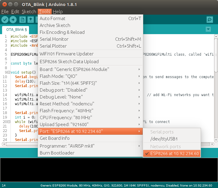
Next, change the interval on line 59 from 1000 to 500 milliseconds, and click upload. You should get a password prompt: enter «esp8266». This password is set on line 31, so you can change it if you want to. You can also delete line 31 altogether to use it without a password, but it’s not recommended — for obvious security reasons.
The sketch should upload just fine, and once the ESP has reset itself, the LED should blink twice as fast.
Once in a while, you might get an error saying
[ERROR]: No Answer
. If this happens, just enter the password, and try again.
Serial Monitor OTA
Using the Serial Monitor over Wi-Fi is not possible (yet?). When you try to open it, you’ll be prompted a password, entering the password won’t work, because there is no SSH support to access the ESP’s console.
You can use a different program to get debug output from the physical Serial port. On Windows, you can try Portmon. On Linux, you can try GTKTerm (
sudo apt-get install gtkterm
) or Screen (
sudo apt-get install screen
to install, and
screen /dev/ttyUSB0 115200
or
screen /dev/ttyACM0 115200
to run;
CTRL+A, CTRL+D
to exit).