- Manuals
- Brands
- Euronda Manuals
- Dental equipment
- E9 INSPECTION
- Instruction manual
-
Contents
-
Table of Contents
-
Troubleshooting
-
Bookmarks
Quick Links
Related Manuals for Euronda E9 Inspection

Summary of Contents for Euronda E9 Inspection
-
Page 2
Please also note that Euronda S.p.A. declines all liability for incorrect or insufficient interpretations of the translations of this manual: in the event of a dispute, only the manual written in the Italian language shall apply. -
Page 3: Table Of Contents
Aquafilter INDEX CHAPTER 1 …………………………. 5 GUARANTEE ……………………..5 CERTIFICATE OF GUARANTEE (facsimile)…………….5 CHAPTER 2 …………………………. 6 REFERENCE STANDARDS ………………….6 STAFF REQUIREMENTS ………………….6 USING AND STORING THE MANUAL ………………6 READING THE MANUAL: SYMBOLS AND CONVENTIONS …………7 HOW TO OBTAIN A NEW COPY OF THE MANUAL …………..
-
Page 4
Aquafilter CHAPTER 7 …………………………35 PROGRAM MENU ……………………35 SELECTING A STERILIZATION CYCLE ……………….36 7.2.1 Start-up, execution and end of a cycle………………38 7.2.2 Information on process parameters …………………40 SELECTING A TEST ……………………41 7.3.1 Start-up, execution and end of a test ………………41 7.3.2 Information on test parameters ………………..44 MANUALLY STOPPING A CYCLE OR A TEST …………….45 7.4.1 Manually stopping a cycle before or during the sterilization phase ……….45 7.4.2 Manually stopping a cycle after the sterilization phase ……………46… -
Page 5
Aquafilter APPENDIX 3 …………………………72 Positioning the load ……………………..72 APPENDIX 4 …………………………73 Unloading and preserving sterilized instruments ……………….73 APPENDIX 5 …………………………74 Description of programs …………………….74 APPENDIX 6 …………………………76 Description of Tests ……………………..76 APPENDIX 7 …………………………79 Validating the cycles ……………………..79 APPENDIX 8 …………………………80 Quality of process water …………………….80 APPENDIX 9 …………………………81 Troubleshooting ……………………….81… -
Page 6: Chapter 1
CHAPTER 1 GUARANTEE Euronda S.p.A. guarantees the quality of its equipment, if used in accordance with the instructions contained in this manual, according to the conditions indicated in the Certificate of Guarantee (see chap. 1.2). ATTENTION: the CUSTOMER must fill in all parts of the COUPON in the certificate of guarantee and send it to EURONDA S.p.A.
-
Page 7: Chapter 2
The responsible authority is legally responsible for the installation, operation and use of the unit. USING AND STORING THE MANUAL This manual refers to the following series and models of appliance: Series Model ® E9 INSPECTION ® E9 INSPECTION ® E9 INSPECTION ®…
-
Page 8: Reading The Manual: Symbols And Conventions
The partial or total photocopying of the text and illustrations is strictly forbidden. Euronda S.p.A. reserves the right to make modifications or improvements to the manual or equipment without notice and without being obliged to update previous production and manuals. The information contained in this manual refers to the unit the characteristics of which are specified in chap.
-
Page 9
Aquafilter Send your request to the following address: EURONDA SPA Via dell’Artigianato, 7 I- 36030 Montecchio Precalcino Vicenza — Italy Tel. 0039 – (0)445 329811 Fax 0039 – (0)445 865246 E-mail info@euronda.com E9_InspectionRecMed_Ing_rev12 – 07/05/13… -
Page 10: Chapter 3
Aquafilter CHAPTER 3 GENERAL SAFETY WARNINGS Before using the equipment, read the safety information carefully. Non-observance could cause accidents or damage to the machine. Before using the unit, operators must have perfectly understood the meanings and functions of all the controls.
-
Page 11: Intended Use
Disconnection of power supply to the resistances resistance heating the chamber (mod. E9 ® ® Inspection and E9 Inspection Recorder) Safety valve, complying with the PED 97/23/CE Discharge of steam and re-balancing of pressure to standards, for protecting the unit from over-pressure safety values E9_InspectionRecMed_Ing_rev12 –…
-
Page 12
It is forbidden to remove, modify, tamper with or in any way neutralize the safety devices. Euronda S.p.A. declines all liability for accidents to people or damage or malfunctions of the unit if the above instruction is not observed. -
Page 13: Residue Risks
Aquafilter RESIDUE RISKS During the normal work cycle, the operator is exposed to certain risks that cannot be completely eliminated due to the nature of the unit. Danger of contamination. In case of unsuccessful sterilisation or a possible fault, the used water and any parts directly or indirectly in contact with the load may contain contaminating residues.
-
Page 14: Chapter 4
(chap. 4.3 “Description of contents”); there is no evident damage. If any damage or missing parts are discovered, inform the hauler, wholesaler or Euronda S.p.A immediately, providing all details. Handle the packed unit as described in chap. 6.1. “Work environment: positioning” (Fig. 6.1-1).
-
Page 15: Chapter 5
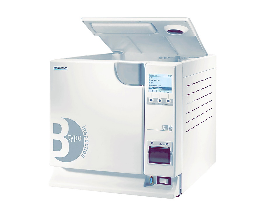
Aquafilter CHAPTER 5 DESCRIPTION OF UNIT totally automatic steam sterilizer for sterilizing instruments both loose and packed in bags. 5.1.1 Front elements 1. Control panel. Used to set, visualize and control all the functions of the unit and to print useful information. The functions of the various buttons explained…
-
Page 16: Upper Elements
Aquafilter 5.1.3 Upper elements 1. Manual filling inlet for distilled water. 2. Compartment for storing objects. 3. Tank, situated inside the unit, under the object-storage compartment Fig. 5.1.3-1 5.1.4 Description of control panel LCD graphic display (320×240 dots). Includes a control bar, always present, that refers directly to the 3-button pushbutton panel situated beneath it.
-
Page 17: Overall Space Required
Aquafilter OVERALL SPACE REQUIRED Overall dimensions of the machine with door closed (fig. 5.2-1): E9 Inspection® — Recorder — Med 18 E9 Inspection® — Recorder — Med 24 L = 450 mm H = 445 mm D = 610 mm Overall dimensions of the machine with door open (fig.5.2-1):…
-
Page 18: Technical Data And Noise
Aquafilter TECHNICAL DATA AND NOISE E9 Inspection ® — Recorder — Med E9 Inspection ® — Recorder — Med CHARACTERISTICS 230 V, 200 V Power supply voltage 50 / 60 Hz Mains frequency 2300 W / 2300 W / 1400 W…
-
Page 19: Rating Plate
Aquafilter Fig. 5.3-1 5.3.1 Rating plate The rating plate (Fig. 5.3.1-1) lists the main data and characteristics of the unit, the information required to identify it when ordering spare parts and/or when requesting information. E9 18 L E9 24 L Fig.
-
Page 20
Aquafilter regardless of whether the cycle was successful or not and regardless of whether it was stopped manually or an alarm was generated. The function of printing the summary report can be excluded if desired (chap. 9.3.1 “Inactivating the internal printer”). The printer only works if paper is inserted. -
Page 21: Integrated Printer For The Recorder Version
Aquafilter Rolls should be kept in a dry place with humidity of no more than 70% and direct temperature lower than 35° centigrade. 5.4.2 Integrated printer for the RECORDER version The RECORDER version of the E9 autoclave features a thermal printer integrated in the front panel and issues self-adhesive labels providing traceability for the material in pouches.
-
Page 22
Aquafilter Avoid direct contact with materials in polyvinyl, as well as solvents and various derivatives (filing envelopes in PVC, acrylics and paper treated with ammonia vapours). Rolls should be kept in a dry place with humidity of no more than 70% and direct temperature lower than 35°… -
Page 23
Aquafilter Select the number of labels: the number of labels to print at the end of the sterilisation process can be selected. If the process is unsuccessful, just the report showing the fault error code is printed. E9_InspectionRecMed_Ing_rev12 – 07/05/13… -
Page 24: Chapter 6
Aquafilter CHAPTER 6 WORK ENVIRONMENT: POSITIONING The unit is packed as follows: covered with a hood in polyethylene with blisters, protected by totally recyclable mouldings in foamed polyethylene, and placed inside a corrugated cardboard box, certified for transportation by sea. Lift the unit with care and do not turn it upside down.
-
Page 25: Installing The Unit
Aquafilter Fig. 6.1-3 Fig. 6.1-4 INSTALLING THE UNIT Installation is a fundamental operation for the subsequent use and correct functioning of the unit. ATTENTION: the unit MUST be installed by specialised technicians. After installing the unit, always fill out the installation sheet and update the service booklet, completing the space for installation with the respective date and signature.
-
Page 26: Electrical Connections
(see chap. 5.3.1 “Rating plate”). Have the system checked by qualified personnel. EURONDA S.p.A DECLINES ALL LIABILITY IF THE ABOVE IS NOT OBSERVED. E9_InspectionRecMed_Ing_rev12 – 07/05/13…
-
Page 27: First Start-Up
6.5.1 Using the control panel for the INSPECTION version ® The E9 INSPECTION steam sterilizer is complete with an LCD graphic user interface (1 of Fig.6.5-1), with a control bar (2 of Fig. 6.5-1) that is always situated in its lower section, in correspondence with the 3-button pushbutton panel situated beneath it (3-4-5 of Fig.
-
Page 28
Aquafilter In lists that contain several items, if the first or the last item is selected, the two or scroll arrows disappear from the control bar, indicating that one of the two items has been selected. When the words “PROCESS CONTROLLER” appear in the screens, it means that the management system of the unit wants to “warn or inform”… -
Page 29: Using The Control Panel For The Med Version
Aquafilter 6.5.2 Using the control panel for the MED version ® The E9 MED steam sterilizer is supplied complete with an alphanumeric LCD user interface (1 of Fig. 6.5.4) with function buttons located in the centre of the control panel. The three buttons on the pushbutton panel (2, 3, 4 of Fig.
-
Page 30: Installation Menu
INSTALLATION MENU This menu is to be used by a specialised technician authorised by Euronda S.p.A, who registers the date of installation of the unit. However, in order to run a work test cycle before actually installing the unit, proceed as follows.
-
Page 31
Aquafilter Setting Date and Time — If YES is pressed, the Date/time setting Using the and keys, select the correct screen appears. — If NO is pressed, you go to the Program day, press OK to pass on to the choice of Menu (chap. -
Page 32
Aquafilter User Registration Complete the fields, using the and keys to scroll through the letters of the alphabet (for the procedure, see the screens to be completed in chap. 8.1.2 “User Registration”), then press OK to move on to the Program Menu (chap. 7.1). The Installation Menu will no longer appear the next time the unit is switched on. -
Page 33: Tanks: Instructions For Filling And Draining
Aquafilter TANKS: INSTRUCTIONS FOR FILLING AND DRAINING The unit features two separate tanks: one for the clean water required for the cycles, and one for the used water that is collected at the end of the cycles. Both tanks are connected with drain valves. Filling with distilled water for the first time 1.
-
Page 34
Aquafilter Adding clean water 1. Empty the inner tank for collecting used water as described below in the par. “Emptying used water”. 2. Fill the clean water tank with fresh clean water, using the respective inlet (2 of Fig. 6.7-1). WARNING: always use good quality clean water (Appendix 8 “Quality of process water”). -
Page 35
Maximum load Never exceed the max. load specified in Appendix 5 “Description of Programs”. Always observe the maximum load, established and checked by Euronda S.p.A., for each solid material to sterilize. The maximum internal load of the unit is shown in Appendix 5. -
Page 36: Chapter 7
Aquafilter CHAPTER 7 PROGRAM MENU Before beginning to operate the unit, carefully read all the warnings indicated in this manual, especially chap. 3 “Safety”. NEVER LIFT the upper cover that covers the object-storage compartment and the water inlet during the sterilization cycle. Once the installation procedure has been carried out (chap.
-
Page 37: Selecting A Sterilization Cycle
Aquafilter SELECTING A STERILIZATION CYCLE From the Program Menu, use the and keys to select the program desired (one of the first three items), then press OK to confirm. This screen appears only if the name of the operator is recorded following the instructions of chap.
-
Page 38
Aquafilter For solid loads not exceeding 0,6 kg and for porous loads not exceeding 0,2 kg is possible to execute a swift cycle that allows to sterilize the load in a time of 25-28 minutes. The RAPIDO cycle includes 5 fixed minutes of drying that allows the load to get dried even if put into envelopes. -
Page 39: Start-Up, Execution And End Of A Cycle
Aquafilter 7.2.1 Start-up, execution and end of a cycle If the AFNOR block is enabled, the machine is programmed to perform cycle B 134 PRION. A password must be entered to perform the other cycles (see annex 11). After pressing the START button to begin the selected cycle, the screen below appears that in this case, purely as an example, refers to cycle B 134, The same procedures and the same type of information indicated below also apply to the other two cycles B 134 PRION, B 121, B134 RAPIDO.
-
Page 40
Aquafilter Pressure levelling For optimum drying, open the door at the Once this has been performed, the Cycle end of the cycle and leave the sterilized End screen appears again. objects on the trays for about 5 minutes before removing them. When the door is opened, the Program Menu screen appears. -
Page 41: Information On Process Parameters
Aquafilter 7.2.2 Information on process parameters Additional information on the parameters of a cycle in course can be obtained by pressing INFO from the Cycle in progress screen. With INFO, the cycle control screen opens. Description of screen P: In this screen, the unit of measure for pressure P is expressed in absolute terms in kPa.
-
Page 42: Selecting A Test
Aquafilter SELECTING A TEST In order to constantly verify the efficiency of the unit, it is extremely important to perform certain tests, at the times recommended in Appendix 6 “Description of tests”. In order to assist the user in periodically performing these tests, the unit can activate memorandum messages.
-
Page 43
Aquafilter Start test Description of Test in progress screen — With , you return to the Test selection P: In this screen, the unit of measure for screen. pressure P is expressed in relative terms in — With START, you begin the test, and the bar. -
Page 44
Aquafilter If, however, the test is completed, with a positive outcome, the following screen appears: At this point, the door release symbol indicates that the door can be opened, and you return to the Program Menu. If the test is completed but gives a negative outcome, the E34 alarm message appears (see “Appendix 9”). -
Page 45: Information On Test Parameters
Aquafilter 7.3.2 Information on test parameters Additional information on the parameters of a test in course can be obtained by pressing INFO from the Test in progress screen. With INFO, the test control screen opens. Description of screen P: In this screen, the unit of measure for pressure P is expressed in absolute terms in kPa.
-
Page 46: Manually Stopping A Cycle Or A Test
Aquafilter MANUALLY STOPPING A CYCLE OR A TEST A cycle or a test can be stopped at any time, both whether it is still in progress and if it has already been completed. 7.4.1 Manually stopping a cycle before or during the sterilization phase In the Cycle in progress screen that, solely as an example, refers to cycle B 134 in the figure below, press the STOP button.
-
Page 47: Manually Stopping A Cycle After The Sterilization Phase
Aquafilter 7.4.2 Manually stopping a cycle after the sterilization phase With STOP, the screen for manually Stop cycle stopping the cycle in progress opens. — With NO, you return to the previous Start Cycle screen. — With YES, the following screens for manually stopping the cycle are activated.
-
Page 48: Manually Stopping A Test In Progress
Aquafilter Maintain drying Pressure levelling With OK, the maintain drying operation is Once this has been performed, the end-of- interrupted and the unit performs the cycle screen appears again. pressure levelling. For optimum drying, open the door at the end of the cycle and leave the sterilized objects on the trays for about 5 minutes before removing them.
-
Page 49: Power Blackouts
Aquafilter A phase lasting a few minutes follows, to — With DOOR, consent is given to open the eliminate the steam from the sterilization door (the symbol changes to ), and you chamber restore pressure return to the Program Menu. atmospheric level.
-
Page 50: Chapter 8
3. SERVICE: management of the cycles and of the printing functions (see chap. 9 “Managing the counter menu and memory and printing functions”). 4. DIAGNOSTICS: section reserved to specialized technicians authorized by Euronda S.p.A., protected by a password. If the user accidentally enters the respective screen, he must go back by means of the specific return button.
-
Page 51: Selecting The Language
Aquafilter 8.1.1 Selecting the language After selecting the item Language from the Settings Menu, the screen below appears. The tick symbol appears automatically on the language selected during the first start-up of the unit (chap. 6.6 “Installation Menu”). With the and keys, select the new language, then press OK to confirm;…
-
Page 52: Setting Date And Time
Aquafilter 8.1.3 Setting date and time After selecting the item Date/Time from the Settings Menu, the screen below appears. Setting Date and Time Using the and keys, choose the correct day, press OK to move to the choice of the month and so on up to the minutes.
-
Page 53: Adjusting The Contrast On The Lcd Display
Aquafilter If you possess the “E-Memory-System” optional, all the data can be registered directly in the software and then exported to the unit, thus making it possible to avoid writing all the data using the small keyboard on the screen. Name operator 1 After the record of the operator, the display shows Name operator 2…
-
Page 54: Selecting Active Cycles
Aquafilter Temperature The first time you access this screen, the Tick symbol appears next to the item °C; use the and keys to select the new unit of measure and then press OK. — With you go back to the previous screen. In the screen regarding the INFO of the cycle, pressure is always expressed in kPa, and the temperature in °C, regardless of the unit of measure selected.
-
Page 55: Setting The Water Supply System
Aquafilter Example for the Vacuum test. Using the Memorandum Test Using the and keys, select the item and keys, select the interval of time desired, then press OK to confirm. between one memorandum and the next — With …
-
Page 56: Chapter 9
Aquafilter CHAPTER 9 SERVICE MENU From the Main Menu, use the key to — Use the and keys to choose Cycle select the item Service, then press OK to counters to display the number of cycles confirm. performed, or — Memory-print functions to print the data regarding one or more of the last 40 cycles.
-
Page 57: Memory And Print Functions
Aquafilter MEMORY AND PRINT FUNCTIONS — Use the and keys to choose the item This screen appears if one of the following items has been selected: Total cycles — OK desired and confirm the choice with OK. — With you go back to the Service Menu. cycles — Stop cycles or Alarm cycles.
-
Page 58: Inactivating The Internal Printer
Aquafilter 9.3.1 Inactivating the internal printer — Use the and key to select the item — The unit has been pre-set on Active (prints Print and confirm with OK. at the end of each cycle); select Inactive to exclude these print-outs.
-
Page 59: Chapter 10
ALL MAINTENANCE OPERATIONS MAY ONLY BE PERFORMED BY THE RESPONSIBLE AUTHORITY OR BY THE TECHNICIANS AUTHORISED BY THE ASSISTANCE SERVICE OF EURONDA S.p.A. Observe the intervals prescribed or shown in this manual. The E9 activates memorandum messages to assist the user in performing both the ordinary and the extraordinary maintenance operations.
-
Page 60: Periodic Maintenance
Aquafilter 10.2 PERIODIC MAINTENANCE Just like all electric units, this unit must be correctly used, serviced and checked at regular intervals. These precautions will ensure the unit works continuously, safely and effectively. To prevent operator hazards, the unit must be subject to regular checks and servicing by the technical assistance service.
-
Page 61
Aquafilter Cleaning the sterilization chamber, accessories, door and seal If the counters are active, the following memorandum message appears when the number of cycles pre-set by the manufacturer is reached: WARNING: DISCONNECT THE POWER SUPPLY BEFORE STARTING WORK. Non- observance may cause serious injury to people and may seriously damage the unit. Sterilization chamber Clean the sterilization chamber thoroughly (Fig. -
Page 62
Aquafilter Fig. 10.2-3 To maintain the unit in good working order, periodically clean all the external parts using a soft cloth and normal neutral detergents or just water (do not use abrasive products). Do NOT wash the unit with direct sprays or high-pressure jets or water, since any infiltration into the electrical components could prejudice the working of the machine and the safety systems. -
Page 63
Aquafilter Fig. 10.2-4 4. Remove the cover in order to access the tanks: unscrew the 5 screws (Fig. 10.2-5); lift the cover by 45° (Fig. 10.2-6) and pull it towards you (Fig. 10.2.7). Fig. 10.2-5 Fig. 10.2-6 Fig. 10.2-7 5. Carefully clean the tanks with the sponge supplied and water, using it on the spongy side and not on the abrasive side. -
Page 64: Periodic Maintenance
Aquafilter 7. Rinse thoroughly and empty the water used for this operation. 8. Run a sterilization cycle without loading the unit. WARNING: while performing all cleaning operations, be careful not to damage the floating sensors situated in the tanks. 10.2.1 Periodic maintenance WARNING: DISCONNECT POWER SUPPLY BEFORE STARTING WORK.
-
Page 65: Adjusting The Closing Mechanism
Aquafilter 10.2.2 Adjusting the closing mechanism WARNING: HIGH TEMPERATURE. Only perform this operation when the machine is cold. The closing mechanism of the unit occasionally requires adjusting due to normal settling of mechanical parts and wear on the seal gasket. This is particularly important as a poor seal may prevent the pressure from increasing to the level set for the selected program and therefore jeopardise the result of the cycle.
-
Page 66: Extraordinary Maintenance
Service. Do not reset the thermostat again. PERFORM THIS OPERATION JUST ONCE. 10.3 EXTRAORDINARY MAINTENANCE Any jobs not mentioned above are considered as extraordinary maintenance. In these cases, contact specialists authorised by Euronda S.p.A. ATTENTION: extraordinary maintenance must be performed by qualified staff only.
-
Page 67
After 1000 cycles or after two years from installation (the date can be seen at the bottom of the screen), a memorandum message appears recommending a general overhaul of the unit. This can only be performed by specialists authorised by Euronda S.p.A. The reminder message appears each time the unit is switched on, until the overhaul has been performed. -
Page 68: Rusting
Aquafilter Cleaning the steam generator filter (E9 Inspection and E9 Inspection Recorder) If necessary, cleaning the steam generator filter. Unscrew the filter as showed in the picture and clean it with water. Take care that the screw or other object fall down into the generator.
-
Page 69
Aquafilter WARNING: DISCONNECT POWER SUPPLY BEFORE STARTING WORK. Non-observance may cause serious injury to people or may seriously damage the unit. If rust forms in the unit, clean the walls of the sterilization chamber and the tray holder using special products for stainless steel, as described previously in the paragraph “Cleaning the sterilization chamber, accessories, door and gasket”. -
Page 70: Chapter 11
If the unit is sold, hand over all the technical documentation to the new purchaser, inform him/her about any repair work carried out and how to use and service the machine. Also inform Euronda S.p.A. of the sale and provide it with data about the new purchaser. E9_InspectionRecMed_Ing_rev12 – 07/05/13…
-
Page 71: Preparing The Instruments For Sterilization
Aquafilter APPENDIX 1 Preparing the instruments for sterilization A correct sterilization depends on the processes described below being carried out correctly; these are all equally important and, therefore, care must be taken while performing them. 1. Preparing the instruments to sterilize 2.
-
Page 72: Packaging
Packaging methods that make it possible to avoid partial withdrawals and that allow for mono-patient use are optimum. ® WARNING: use Euronda Eurosteril sterilization tape rolls to wrap objects or use pouches or rolls marked CE in accordance with Directive 93/42.
-
Page 73: Positioning The Load
Aquafilter APPENDIX 3 Positioning the load The way in which the load to sterilize is arranged is also considerably important to the sterilization process. Always observe the maximum load indicated in this manual, a value that has been tested by the manufacturer and that is therefore valid.
-
Page 74: Unloading And Preserving Sterilized Instruments
Aquafilter APPENDIX 4 Unloading and preserving sterilized instruments The material is at the greatest risk of contamination while it is still hot, because the barrier capabilities of the packaging materials are much lower in the presence of residual humidity, compared to an ambient temperature situation.
-
Page 75: Description Of Programs
Aquafilter APPENDIX 5 Description of programs The E9 unit can perform three sterilization cycles; the parameters of each cycle are summarised in the table below: Cycle B134 RAPIDO Parameters B134 B134 PRION B121 / B134 PRION RAPIDO 18 litres – 24 18 litres –…
-
Page 76
Aquafilter The symbols (2b, 3b, etc.) after the code of the phase refer to the software instructions. The various sterilisation cycles are now described one by one: as they are all B-type cycles, they can sterilise any type of load, whether it be porous, solid or hollow. In all cases, the recommendations given by the manufacturer regarding sterilization methods and times should be followed. -
Page 77: Description Of Tests
Aquafilter APPENDIX 6 Description of Tests It is important to periodically verify the performance of the unit by performing the appropriate tests; E9 can perform three different ones: B&D test Vacuum test Helix test The parameters of the respective cycles are as follows: Parameter Cycles VACUUM…
-
Page 78
Aquafilter In order to achieve a correct result, the test must be carried out with the unit cold, i.e. within 3 minutes from machine start-up. If the test is selected when the device has already reached a sufficiently high temperature, the message indicating that the vacuum test can no longer be carried out will appear in the display. -
Page 79
Aquafilter Helix test The Helix test represents a hollow A-type load, i.e. the load with the most critical characteristics. The test consists of a tube in polytetrafluoroethylene (PTFE) with a length of 150mm and internal diameter of 2mm The Helix test simulates the performance of the unit with respect to the sterilization of hollow loads, in particular: the efficiency of the preliminary vacuum and the penetration of steam within the pores the temperature and pressure values of the saturated steam during the sterilization phase… -
Page 80: Validating The Cycles
Aquafilter APPENDIX 7 Validating the cycles With reference to standard EN 13060, the following cycles have been validated: B134 B134 PRION B121 B134 RAPIDO B134 PRION RAPIDO Dynamic pressure chamber of the sterilizer Air leakage Empty chamber Solid load Small porous articles Light porous loads Full porous loads Hollow load B…
-
Page 81: Quality Of Process Water
Aquafilter APPENDIX 8 Quality of process water With reference to standard EN 13060, the table below indicates the recommended limit values (maximum) for contaminating agents, as well as the chemical-physical characteristics of the water used for condensate* and inlet water. * Condensate is produced by the steam that was formed by the empty chamber of the sterilizer.
-
Page 82: Troubleshooting
APPENDIX 9 Troubleshooting Euronda E9 is equipped with a system for controlling all the components of the unit; when the Process Controller detects a fault either in a component or in the overall behaviour of the machine, an error message appears, preceded by an intermediate “Please wait”…
-
Page 83
Aquafilter 1 Pressure leak from hydraulic 1 Check for leaks Insufficient pressure circuit. during the sterilisation 2 Safety thermostat tripped 2 Reset safety thermostat phase 3 Heater faulty 3 Check generator heater. Pressure sensor out of calibration Check the probe and recalibrate Elevated temperature if necessary. -
Page 84
Aquafilter Leak from hydraulic circuit Check the tubes, unions, porthole Vacuum test: leak during and electrovalves for leaks hold phase Rate of leak ::::::::: Incorrect heating during test Repeat the test. If the problem Vacuum test: temperature persists, contact an authorised out of set values technician 1 Electrovalve faulty… -
Page 85
Aquafilter 1 Maximum level sensor faulty 1 Replace sensor Clean water tank: 2 Aquafilter electrovalve faulty 2 Replace Aquafilter MAX level sensor inactive electrovalve Data not transferred to external Check the external memory is External memory: data memory correctly connected to the serial transfer error port, disconnect and reconnect the external memory… -
Page 86: Description Of Optional Devices
Aquafilter APPENDIX 10 Description of optional devices Aquafilter Deionizer The Aquafilter Deionizer is a device that makes it possible to obtain water for feeding the tank of the unit by connecting directly to the main water supply system. The water thus obtained has characteristics that comply with the table shown in Appendix 8.
-
Page 87: Afnor Block
Aquafilter APPENDIX 11 AFNOR block If the AFNOR block is enabled (for France), the machine is programmed to perform the B 134 PRION cycle. A password must be entered to perform the other cycles. Running the cycle After selecting the cycle, the run screen is displayed (in this case it is cycle B 134) — press …
-
Page 88
Aquafilter EURONDA S.p.A. Via dell’Artigianato, 7 — 36030 Montecchio Precalcino (VI) — ITALY Tel. +39 0445 329811 — Fax +39 0445 865246 — Internet: www.euronda.com — E-mail: info@euronda.com E9_InspectionRecMed_Ing_rev12 – 07/05/13…
- Manuals
- Brands
- Euronda Manuals
- Dental equipment
- E9 INSPECTION
- Instruction manual
-
Contents
-
Table of Contents
-
Troubleshooting
-
Bookmarks
Quick Links
Related Manuals for Euronda E9 Inspection
Summary of Contents for Euronda E9 Inspection
-
Page 2
Please also note that Euronda S.p.A. declines all liability for incorrect or insufficient interpretations of the translations of this manual: in the event of a dispute, only the manual written in the Italian language shall apply. -
Page 3: Table Of Contents
Aquafilter INDEX CHAPTER 1 …………………………. 5 GUARANTEE ……………………..5 CERTIFICATE OF GUARANTEE (facsimile)…………….5 CHAPTER 2 …………………………. 6 REFERENCE STANDARDS ………………….6 STAFF REQUIREMENTS ………………….6 USING AND STORING THE MANUAL ………………6 READING THE MANUAL: SYMBOLS AND CONVENTIONS …………7 HOW TO OBTAIN A NEW COPY OF THE MANUAL …………..
-
Page 4
Aquafilter CHAPTER 7 …………………………35 PROGRAM MENU ……………………35 SELECTING A STERILIZATION CYCLE ……………….36 7.2.1 Start-up, execution and end of a cycle………………38 7.2.2 Information on process parameters …………………40 SELECTING A TEST ……………………41 7.3.1 Start-up, execution and end of a test ………………41 7.3.2 Information on test parameters ………………..44 MANUALLY STOPPING A CYCLE OR A TEST …………….45 7.4.1 Manually stopping a cycle before or during the sterilization phase ……….45 7.4.2 Manually stopping a cycle after the sterilization phase ……………46… -
Page 5
Aquafilter APPENDIX 3 …………………………72 Positioning the load ……………………..72 APPENDIX 4 …………………………73 Unloading and preserving sterilized instruments ……………….73 APPENDIX 5 …………………………74 Description of programs …………………….74 APPENDIX 6 …………………………76 Description of Tests ……………………..76 APPENDIX 7 …………………………79 Validating the cycles ……………………..79 APPENDIX 8 …………………………80 Quality of process water …………………….80 APPENDIX 9 …………………………81 Troubleshooting ……………………….81… -
Page 6: Chapter 1
CHAPTER 1 GUARANTEE Euronda S.p.A. guarantees the quality of its equipment, if used in accordance with the instructions contained in this manual, according to the conditions indicated in the Certificate of Guarantee (see chap. 1.2). ATTENTION: the CUSTOMER must fill in all parts of the COUPON in the certificate of guarantee and send it to EURONDA S.p.A.
-
Page 7: Chapter 2
The responsible authority is legally responsible for the installation, operation and use of the unit. USING AND STORING THE MANUAL This manual refers to the following series and models of appliance: Series Model ® E9 INSPECTION ® E9 INSPECTION ® E9 INSPECTION ®…
-
Page 8: Reading The Manual: Symbols And Conventions
The partial or total photocopying of the text and illustrations is strictly forbidden. Euronda S.p.A. reserves the right to make modifications or improvements to the manual or equipment without notice and without being obliged to update previous production and manuals. The information contained in this manual refers to the unit the characteristics of which are specified in chap.
-
Page 9
Aquafilter Send your request to the following address: EURONDA SPA Via dell’Artigianato, 7 I- 36030 Montecchio Precalcino Vicenza — Italy Tel. 0039 – (0)445 329811 Fax 0039 – (0)445 865246 E-mail info@euronda.com E9_InspectionRecMed_Ing_rev12 – 07/05/13… -
Page 10: Chapter 3
Aquafilter CHAPTER 3 GENERAL SAFETY WARNINGS Before using the equipment, read the safety information carefully. Non-observance could cause accidents or damage to the machine. Before using the unit, operators must have perfectly understood the meanings and functions of all the controls.
-
Page 11: Intended Use
Disconnection of power supply to the resistances resistance heating the chamber (mod. E9 ® ® Inspection and E9 Inspection Recorder) Safety valve, complying with the PED 97/23/CE Discharge of steam and re-balancing of pressure to standards, for protecting the unit from over-pressure safety values E9_InspectionRecMed_Ing_rev12 –…
-
Page 12
It is forbidden to remove, modify, tamper with or in any way neutralize the safety devices. Euronda S.p.A. declines all liability for accidents to people or damage or malfunctions of the unit if the above instruction is not observed. -
Page 13: Residue Risks
Aquafilter RESIDUE RISKS During the normal work cycle, the operator is exposed to certain risks that cannot be completely eliminated due to the nature of the unit. Danger of contamination. In case of unsuccessful sterilisation or a possible fault, the used water and any parts directly or indirectly in contact with the load may contain contaminating residues.
-
Page 14: Chapter 4
(chap. 4.3 “Description of contents”); there is no evident damage. If any damage or missing parts are discovered, inform the hauler, wholesaler or Euronda S.p.A immediately, providing all details. Handle the packed unit as described in chap. 6.1. “Work environment: positioning” (Fig. 6.1-1).
-
Page 15: Chapter 5
Aquafilter CHAPTER 5 DESCRIPTION OF UNIT totally automatic steam sterilizer for sterilizing instruments both loose and packed in bags. 5.1.1 Front elements 1. Control panel. Used to set, visualize and control all the functions of the unit and to print useful information. The functions of the various buttons explained…
-
Page 16: Upper Elements
Aquafilter 5.1.3 Upper elements 1. Manual filling inlet for distilled water. 2. Compartment for storing objects. 3. Tank, situated inside the unit, under the object-storage compartment Fig. 5.1.3-1 5.1.4 Description of control panel LCD graphic display (320×240 dots). Includes a control bar, always present, that refers directly to the 3-button pushbutton panel situated beneath it.
-
Page 17: Overall Space Required
Aquafilter OVERALL SPACE REQUIRED Overall dimensions of the machine with door closed (fig. 5.2-1): E9 Inspection® — Recorder — Med 18 E9 Inspection® — Recorder — Med 24 L = 450 mm H = 445 mm D = 610 mm Overall dimensions of the machine with door open (fig.5.2-1):…
-
Page 18: Technical Data And Noise
Aquafilter TECHNICAL DATA AND NOISE E9 Inspection ® — Recorder — Med E9 Inspection ® — Recorder — Med CHARACTERISTICS 230 V, 200 V Power supply voltage 50 / 60 Hz Mains frequency 2300 W / 2300 W / 1400 W…
-
Page 19: Rating Plate
Aquafilter Fig. 5.3-1 5.3.1 Rating plate The rating plate (Fig. 5.3.1-1) lists the main data and characteristics of the unit, the information required to identify it when ordering spare parts and/or when requesting information. E9 18 L E9 24 L Fig.
-
Page 20
Aquafilter regardless of whether the cycle was successful or not and regardless of whether it was stopped manually or an alarm was generated. The function of printing the summary report can be excluded if desired (chap. 9.3.1 “Inactivating the internal printer”). The printer only works if paper is inserted. -
Page 21: Integrated Printer For The Recorder Version
Aquafilter Rolls should be kept in a dry place with humidity of no more than 70% and direct temperature lower than 35° centigrade. 5.4.2 Integrated printer for the RECORDER version The RECORDER version of the E9 autoclave features a thermal printer integrated in the front panel and issues self-adhesive labels providing traceability for the material in pouches.
-
Page 22
Aquafilter Avoid direct contact with materials in polyvinyl, as well as solvents and various derivatives (filing envelopes in PVC, acrylics and paper treated with ammonia vapours). Rolls should be kept in a dry place with humidity of no more than 70% and direct temperature lower than 35°… -
Page 23
Aquafilter Select the number of labels: the number of labels to print at the end of the sterilisation process can be selected. If the process is unsuccessful, just the report showing the fault error code is printed. E9_InspectionRecMed_Ing_rev12 – 07/05/13… -
Page 24: Chapter 6
Aquafilter CHAPTER 6 WORK ENVIRONMENT: POSITIONING The unit is packed as follows: covered with a hood in polyethylene with blisters, protected by totally recyclable mouldings in foamed polyethylene, and placed inside a corrugated cardboard box, certified for transportation by sea. Lift the unit with care and do not turn it upside down.
-
Page 25: Installing The Unit
Aquafilter Fig. 6.1-3 Fig. 6.1-4 INSTALLING THE UNIT Installation is a fundamental operation for the subsequent use and correct functioning of the unit. ATTENTION: the unit MUST be installed by specialised technicians. After installing the unit, always fill out the installation sheet and update the service booklet, completing the space for installation with the respective date and signature.
-
Page 26: Electrical Connections
(see chap. 5.3.1 “Rating plate”). Have the system checked by qualified personnel. EURONDA S.p.A DECLINES ALL LIABILITY IF THE ABOVE IS NOT OBSERVED. E9_InspectionRecMed_Ing_rev12 – 07/05/13…
-
Page 27: First Start-Up
6.5.1 Using the control panel for the INSPECTION version ® The E9 INSPECTION steam sterilizer is complete with an LCD graphic user interface (1 of Fig.6.5-1), with a control bar (2 of Fig. 6.5-1) that is always situated in its lower section, in correspondence with the 3-button pushbutton panel situated beneath it (3-4-5 of Fig.
-
Page 28
Aquafilter In lists that contain several items, if the first or the last item is selected, the two or scroll arrows disappear from the control bar, indicating that one of the two items has been selected. When the words “PROCESS CONTROLLER” appear in the screens, it means that the management system of the unit wants to “warn or inform”… -
Page 29: Using The Control Panel For The Med Version
Aquafilter 6.5.2 Using the control panel for the MED version ® The E9 MED steam sterilizer is supplied complete with an alphanumeric LCD user interface (1 of Fig. 6.5.4) with function buttons located in the centre of the control panel. The three buttons on the pushbutton panel (2, 3, 4 of Fig.
-
Page 30: Installation Menu
INSTALLATION MENU This menu is to be used by a specialised technician authorised by Euronda S.p.A, who registers the date of installation of the unit. However, in order to run a work test cycle before actually installing the unit, proceed as follows.
-
Page 31
Aquafilter Setting Date and Time — If YES is pressed, the Date/time setting Using the and keys, select the correct screen appears. — If NO is pressed, you go to the Program day, press OK to pass on to the choice of Menu (chap. -
Page 32
Aquafilter User Registration Complete the fields, using the and keys to scroll through the letters of the alphabet (for the procedure, see the screens to be completed in chap. 8.1.2 “User Registration”), then press OK to move on to the Program Menu (chap. 7.1). The Installation Menu will no longer appear the next time the unit is switched on. -
Page 33: Tanks: Instructions For Filling And Draining
Aquafilter TANKS: INSTRUCTIONS FOR FILLING AND DRAINING The unit features two separate tanks: one for the clean water required for the cycles, and one for the used water that is collected at the end of the cycles. Both tanks are connected with drain valves. Filling with distilled water for the first time 1.
-
Page 34
Aquafilter Adding clean water 1. Empty the inner tank for collecting used water as described below in the par. “Emptying used water”. 2. Fill the clean water tank with fresh clean water, using the respective inlet (2 of Fig. 6.7-1). WARNING: always use good quality clean water (Appendix 8 “Quality of process water”). -
Page 35
Maximum load Never exceed the max. load specified in Appendix 5 “Description of Programs”. Always observe the maximum load, established and checked by Euronda S.p.A., for each solid material to sterilize. The maximum internal load of the unit is shown in Appendix 5. -
Page 36: Chapter 7
Aquafilter CHAPTER 7 PROGRAM MENU Before beginning to operate the unit, carefully read all the warnings indicated in this manual, especially chap. 3 “Safety”. NEVER LIFT the upper cover that covers the object-storage compartment and the water inlet during the sterilization cycle. Once the installation procedure has been carried out (chap.
-
Page 37: Selecting A Sterilization Cycle
Aquafilter SELECTING A STERILIZATION CYCLE From the Program Menu, use the and keys to select the program desired (one of the first three items), then press OK to confirm. This screen appears only if the name of the operator is recorded following the instructions of chap.
-
Page 38
Aquafilter For solid loads not exceeding 0,6 kg and for porous loads not exceeding 0,2 kg is possible to execute a swift cycle that allows to sterilize the load in a time of 25-28 minutes. The RAPIDO cycle includes 5 fixed minutes of drying that allows the load to get dried even if put into envelopes. -
Page 39: Start-Up, Execution And End Of A Cycle
Aquafilter 7.2.1 Start-up, execution and end of a cycle If the AFNOR block is enabled, the machine is programmed to perform cycle B 134 PRION. A password must be entered to perform the other cycles (see annex 11). After pressing the START button to begin the selected cycle, the screen below appears that in this case, purely as an example, refers to cycle B 134, The same procedures and the same type of information indicated below also apply to the other two cycles B 134 PRION, B 121, B134 RAPIDO.
-
Page 40
Aquafilter Pressure levelling For optimum drying, open the door at the Once this has been performed, the Cycle end of the cycle and leave the sterilized End screen appears again. objects on the trays for about 5 minutes before removing them. When the door is opened, the Program Menu screen appears. -
Page 41: Information On Process Parameters
Aquafilter 7.2.2 Information on process parameters Additional information on the parameters of a cycle in course can be obtained by pressing INFO from the Cycle in progress screen. With INFO, the cycle control screen opens. Description of screen P: In this screen, the unit of measure for pressure P is expressed in absolute terms in kPa.
-
Page 42: Selecting A Test
Aquafilter SELECTING A TEST In order to constantly verify the efficiency of the unit, it is extremely important to perform certain tests, at the times recommended in Appendix 6 “Description of tests”. In order to assist the user in periodically performing these tests, the unit can activate memorandum messages.
-
Page 43
Aquafilter Start test Description of Test in progress screen — With , you return to the Test selection P: In this screen, the unit of measure for screen. pressure P is expressed in relative terms in — With START, you begin the test, and the bar. -
Page 44
Aquafilter If, however, the test is completed, with a positive outcome, the following screen appears: At this point, the door release symbol indicates that the door can be opened, and you return to the Program Menu. If the test is completed but gives a negative outcome, the E34 alarm message appears (see “Appendix 9”). -
Page 45: Information On Test Parameters
Aquafilter 7.3.2 Information on test parameters Additional information on the parameters of a test in course can be obtained by pressing INFO from the Test in progress screen. With INFO, the test control screen opens. Description of screen P: In this screen, the unit of measure for pressure P is expressed in absolute terms in kPa.
-
Page 46: Manually Stopping A Cycle Or A Test
Aquafilter MANUALLY STOPPING A CYCLE OR A TEST A cycle or a test can be stopped at any time, both whether it is still in progress and if it has already been completed. 7.4.1 Manually stopping a cycle before or during the sterilization phase In the Cycle in progress screen that, solely as an example, refers to cycle B 134 in the figure below, press the STOP button.
-
Page 47: Manually Stopping A Cycle After The Sterilization Phase
Aquafilter 7.4.2 Manually stopping a cycle after the sterilization phase With STOP, the screen for manually Stop cycle stopping the cycle in progress opens. — With NO, you return to the previous Start Cycle screen. — With YES, the following screens for manually stopping the cycle are activated.
-
Page 48: Manually Stopping A Test In Progress
Aquafilter Maintain drying Pressure levelling With OK, the maintain drying operation is Once this has been performed, the end-of- interrupted and the unit performs the cycle screen appears again. pressure levelling. For optimum drying, open the door at the end of the cycle and leave the sterilized objects on the trays for about 5 minutes before removing them.
-
Page 49: Power Blackouts
Aquafilter A phase lasting a few minutes follows, to — With DOOR, consent is given to open the eliminate the steam from the sterilization door (the symbol changes to ), and you chamber restore pressure return to the Program Menu. atmospheric level.
-
Page 50: Chapter 8
3. SERVICE: management of the cycles and of the printing functions (see chap. 9 “Managing the counter menu and memory and printing functions”). 4. DIAGNOSTICS: section reserved to specialized technicians authorized by Euronda S.p.A., protected by a password. If the user accidentally enters the respective screen, he must go back by means of the specific return button.
-
Page 51: Selecting The Language
Aquafilter 8.1.1 Selecting the language After selecting the item Language from the Settings Menu, the screen below appears. The tick symbol appears automatically on the language selected during the first start-up of the unit (chap. 6.6 “Installation Menu”). With the and keys, select the new language, then press OK to confirm;…
-
Page 52: Setting Date And Time
Aquafilter 8.1.3 Setting date and time After selecting the item Date/Time from the Settings Menu, the screen below appears. Setting Date and Time Using the and keys, choose the correct day, press OK to move to the choice of the month and so on up to the minutes.
-
Page 53: Adjusting The Contrast On The Lcd Display
Aquafilter If you possess the “E-Memory-System” optional, all the data can be registered directly in the software and then exported to the unit, thus making it possible to avoid writing all the data using the small keyboard on the screen. Name operator 1 After the record of the operator, the display shows Name operator 2…
-
Page 54: Selecting Active Cycles
Aquafilter Temperature The first time you access this screen, the Tick symbol appears next to the item °C; use the and keys to select the new unit of measure and then press OK. — With you go back to the previous screen. In the screen regarding the INFO of the cycle, pressure is always expressed in kPa, and the temperature in °C, regardless of the unit of measure selected.
-
Page 55: Setting The Water Supply System
Aquafilter Example for the Vacuum test. Using the Memorandum Test Using the and keys, select the item and keys, select the interval of time desired, then press OK to confirm. between one memorandum and the next — With …
-
Page 56: Chapter 9
Aquafilter CHAPTER 9 SERVICE MENU From the Main Menu, use the key to — Use the and keys to choose Cycle select the item Service, then press OK to counters to display the number of cycles confirm. performed, or — Memory-print functions to print the data regarding one or more of the last 40 cycles.
-
Page 57: Memory And Print Functions
Aquafilter MEMORY AND PRINT FUNCTIONS — Use the and keys to choose the item This screen appears if one of the following items has been selected: Total cycles — OK desired and confirm the choice with OK. — With you go back to the Service Menu. cycles — Stop cycles or Alarm cycles.
-
Page 58: Inactivating The Internal Printer
Aquafilter 9.3.1 Inactivating the internal printer — Use the and key to select the item — The unit has been pre-set on Active (prints Print and confirm with OK. at the end of each cycle); select Inactive to exclude these print-outs.
-
Page 59: Chapter 10
ALL MAINTENANCE OPERATIONS MAY ONLY BE PERFORMED BY THE RESPONSIBLE AUTHORITY OR BY THE TECHNICIANS AUTHORISED BY THE ASSISTANCE SERVICE OF EURONDA S.p.A. Observe the intervals prescribed or shown in this manual. The E9 activates memorandum messages to assist the user in performing both the ordinary and the extraordinary maintenance operations.
-
Page 60: Periodic Maintenance
Aquafilter 10.2 PERIODIC MAINTENANCE Just like all electric units, this unit must be correctly used, serviced and checked at regular intervals. These precautions will ensure the unit works continuously, safely and effectively. To prevent operator hazards, the unit must be subject to regular checks and servicing by the technical assistance service.
-
Page 61
Aquafilter Cleaning the sterilization chamber, accessories, door and seal If the counters are active, the following memorandum message appears when the number of cycles pre-set by the manufacturer is reached: WARNING: DISCONNECT THE POWER SUPPLY BEFORE STARTING WORK. Non- observance may cause serious injury to people and may seriously damage the unit. Sterilization chamber Clean the sterilization chamber thoroughly (Fig. -
Page 62
Aquafilter Fig. 10.2-3 To maintain the unit in good working order, periodically clean all the external parts using a soft cloth and normal neutral detergents or just water (do not use abrasive products). Do NOT wash the unit with direct sprays or high-pressure jets or water, since any infiltration into the electrical components could prejudice the working of the machine and the safety systems. -
Page 63
Aquafilter Fig. 10.2-4 4. Remove the cover in order to access the tanks: unscrew the 5 screws (Fig. 10.2-5); lift the cover by 45° (Fig. 10.2-6) and pull it towards you (Fig. 10.2.7). Fig. 10.2-5 Fig. 10.2-6 Fig. 10.2-7 5. Carefully clean the tanks with the sponge supplied and water, using it on the spongy side and not on the abrasive side. -
Page 64: Periodic Maintenance
Aquafilter 7. Rinse thoroughly and empty the water used for this operation. 8. Run a sterilization cycle without loading the unit. WARNING: while performing all cleaning operations, be careful not to damage the floating sensors situated in the tanks. 10.2.1 Periodic maintenance WARNING: DISCONNECT POWER SUPPLY BEFORE STARTING WORK.
-
Page 65: Adjusting The Closing Mechanism
Aquafilter 10.2.2 Adjusting the closing mechanism WARNING: HIGH TEMPERATURE. Only perform this operation when the machine is cold. The closing mechanism of the unit occasionally requires adjusting due to normal settling of mechanical parts and wear on the seal gasket. This is particularly important as a poor seal may prevent the pressure from increasing to the level set for the selected program and therefore jeopardise the result of the cycle.
-
Page 66: Extraordinary Maintenance
Service. Do not reset the thermostat again. PERFORM THIS OPERATION JUST ONCE. 10.3 EXTRAORDINARY MAINTENANCE Any jobs not mentioned above are considered as extraordinary maintenance. In these cases, contact specialists authorised by Euronda S.p.A. ATTENTION: extraordinary maintenance must be performed by qualified staff only.
-
Page 67
After 1000 cycles or after two years from installation (the date can be seen at the bottom of the screen), a memorandum message appears recommending a general overhaul of the unit. This can only be performed by specialists authorised by Euronda S.p.A. The reminder message appears each time the unit is switched on, until the overhaul has been performed. -
Page 68: Rusting
Aquafilter Cleaning the steam generator filter (E9 Inspection and E9 Inspection Recorder) If necessary, cleaning the steam generator filter. Unscrew the filter as showed in the picture and clean it with water. Take care that the screw or other object fall down into the generator.
-
Page 69
Aquafilter WARNING: DISCONNECT POWER SUPPLY BEFORE STARTING WORK. Non-observance may cause serious injury to people or may seriously damage the unit. If rust forms in the unit, clean the walls of the sterilization chamber and the tray holder using special products for stainless steel, as described previously in the paragraph “Cleaning the sterilization chamber, accessories, door and gasket”. -
Page 70: Chapter 11
If the unit is sold, hand over all the technical documentation to the new purchaser, inform him/her about any repair work carried out and how to use and service the machine. Also inform Euronda S.p.A. of the sale and provide it with data about the new purchaser. E9_InspectionRecMed_Ing_rev12 – 07/05/13…
-
Page 71: Preparing The Instruments For Sterilization
Aquafilter APPENDIX 1 Preparing the instruments for sterilization A correct sterilization depends on the processes described below being carried out correctly; these are all equally important and, therefore, care must be taken while performing them. 1. Preparing the instruments to sterilize 2.
-
Page 72: Packaging
Packaging methods that make it possible to avoid partial withdrawals and that allow for mono-patient use are optimum. ® WARNING: use Euronda Eurosteril sterilization tape rolls to wrap objects or use pouches or rolls marked CE in accordance with Directive 93/42.
-
Page 73: Positioning The Load
Aquafilter APPENDIX 3 Positioning the load The way in which the load to sterilize is arranged is also considerably important to the sterilization process. Always observe the maximum load indicated in this manual, a value that has been tested by the manufacturer and that is therefore valid.
-
Page 74: Unloading And Preserving Sterilized Instruments
Aquafilter APPENDIX 4 Unloading and preserving sterilized instruments The material is at the greatest risk of contamination while it is still hot, because the barrier capabilities of the packaging materials are much lower in the presence of residual humidity, compared to an ambient temperature situation.
-
Page 75: Description Of Programs
Aquafilter APPENDIX 5 Description of programs The E9 unit can perform three sterilization cycles; the parameters of each cycle are summarised in the table below: Cycle B134 RAPIDO Parameters B134 B134 PRION B121 / B134 PRION RAPIDO 18 litres – 24 18 litres –…
-
Page 76
Aquafilter The symbols (2b, 3b, etc.) after the code of the phase refer to the software instructions. The various sterilisation cycles are now described one by one: as they are all B-type cycles, they can sterilise any type of load, whether it be porous, solid or hollow. In all cases, the recommendations given by the manufacturer regarding sterilization methods and times should be followed. -
Page 77: Description Of Tests
Aquafilter APPENDIX 6 Description of Tests It is important to periodically verify the performance of the unit by performing the appropriate tests; E9 can perform three different ones: B&D test Vacuum test Helix test The parameters of the respective cycles are as follows: Parameter Cycles VACUUM…
-
Page 78
Aquafilter In order to achieve a correct result, the test must be carried out with the unit cold, i.e. within 3 minutes from machine start-up. If the test is selected when the device has already reached a sufficiently high temperature, the message indicating that the vacuum test can no longer be carried out will appear in the display. -
Page 79
Aquafilter Helix test The Helix test represents a hollow A-type load, i.e. the load with the most critical characteristics. The test consists of a tube in polytetrafluoroethylene (PTFE) with a length of 150mm and internal diameter of 2mm The Helix test simulates the performance of the unit with respect to the sterilization of hollow loads, in particular: the efficiency of the preliminary vacuum and the penetration of steam within the pores the temperature and pressure values of the saturated steam during the sterilization phase… -
Page 80: Validating The Cycles
Aquafilter APPENDIX 7 Validating the cycles With reference to standard EN 13060, the following cycles have been validated: B134 B134 PRION B121 B134 RAPIDO B134 PRION RAPIDO Dynamic pressure chamber of the sterilizer Air leakage Empty chamber Solid load Small porous articles Light porous loads Full porous loads Hollow load B…
-
Page 81: Quality Of Process Water
Aquafilter APPENDIX 8 Quality of process water With reference to standard EN 13060, the table below indicates the recommended limit values (maximum) for contaminating agents, as well as the chemical-physical characteristics of the water used for condensate* and inlet water. * Condensate is produced by the steam that was formed by the empty chamber of the sterilizer.
-
Page 82: Troubleshooting
APPENDIX 9 Troubleshooting Euronda E9 is equipped with a system for controlling all the components of the unit; when the Process Controller detects a fault either in a component or in the overall behaviour of the machine, an error message appears, preceded by an intermediate “Please wait”…
-
Page 83
Aquafilter 1 Pressure leak from hydraulic 1 Check for leaks Insufficient pressure circuit. during the sterilisation 2 Safety thermostat tripped 2 Reset safety thermostat phase 3 Heater faulty 3 Check generator heater. Pressure sensor out of calibration Check the probe and recalibrate Elevated temperature if necessary. -
Page 84
Aquafilter Leak from hydraulic circuit Check the tubes, unions, porthole Vacuum test: leak during and electrovalves for leaks hold phase Rate of leak ::::::::: Incorrect heating during test Repeat the test. If the problem Vacuum test: temperature persists, contact an authorised out of set values technician 1 Electrovalve faulty… -
Page 85
Aquafilter 1 Maximum level sensor faulty 1 Replace sensor Clean water tank: 2 Aquafilter electrovalve faulty 2 Replace Aquafilter MAX level sensor inactive electrovalve Data not transferred to external Check the external memory is External memory: data memory correctly connected to the serial transfer error port, disconnect and reconnect the external memory… -
Page 86: Description Of Optional Devices
Aquafilter APPENDIX 10 Description of optional devices Aquafilter Deionizer The Aquafilter Deionizer is a device that makes it possible to obtain water for feeding the tank of the unit by connecting directly to the main water supply system. The water thus obtained has characteristics that comply with the table shown in Appendix 8.
-
Page 87: Afnor Block
Aquafilter APPENDIX 11 AFNOR block If the AFNOR block is enabled (for France), the machine is programmed to perform the B 134 PRION cycle. A password must be entered to perform the other cycles. Running the cycle After selecting the cycle, the run screen is displayed (in this case it is cycle B 134) — press …
-
Page 88
Aquafilter EURONDA S.p.A. Via dell’Artigianato, 7 — 36030 Montecchio Precalcino (VI) — ITALY Tel. +39 0445 329811 — Fax +39 0445 865246 — Internet: www.euronda.com — E-mail: info@euronda.com E9_InspectionRecMed_Ing_rev12 – 07/05/13…
CONTENTS
1 — INTRODUCTION …………………………………………………………………………………………………. 7
1.1 GENERAL PRECAUTIONS ………………………………………………………………………………………………………………………… 7
2 — SAFETY …………………………………………………………………………………………………………….. 9
2.1 GENERAL SAFETY WARNINGS ……………………………………………………………………………………………………………….. 9
2.2 SAFETY DEVICES …………………………………………………………………………………………………………………………………….. 10
2.3 RESIDUE RISKS ……………………………………………………………………………………………………………………………………….. 11
2.4 SAFETY SIGNS ON THE UNIT …………………………………………………………………………………………………………………. 12
3 — TECHNICAL DATA ……………………………………………………………………………………………. 13
3.1 OVERALL SPACE REQUIRED …………………………………………………………………………………………………………………. 13
3.2 TECHNICAL DATA AND NOISE ………………………………………………………………………………………………………………. 14
3.3 QUALITY OF WATER ……………………………………………………………………………………………………………………………… 15
3.4 SERIAL NUMBERS CODING ………………………………………………………………………………………………………………….. 16
4 — INSTALLATION ………………………………………………………………………………………………… 17
4.1 POSITIONING THE UNIT …………………………………………………………………………………………………………………………. 17
4.2 INSTALLING THE UNIT …………………………………………………………………………………………………………………………… 18
4.2.1 Installation and adjustement …………………………………………………………………………………………………………………….. 18
4.3 OPERATOR REGISTRATION …………………………………………………………………………………………………………………… 23
4.4 PERFORMING THE VACUUM TEST ……………………………………………………………………………………………………….. 24
4.5 PERFORMING THE B134 CYCLE …………………………………………………………………………………………………………….. 25
5.1 E9 INSPECTION COMPONENTS ……………………………………………………………………………………………………………… 29
5.2.1 Phase 0: Turning on the sterilizer ……………………………………………………………………………………………………………… 32

Паровой стерилизатор euronda e9 — устройство, спроектированное и созданное для стерилизации медицинских, стоматологических, ветеринарных и ортопедических инструментов, которые можно подвергать стерилизации паром при температуре от 121°C до 134°C.
Автоматический скоростной автоклав euronda e9 класса «B» с предвакуумом и вакуумной помпой.
- Тройная система защиты: автономный защитный клапан, защитный термостат, система электронного отключения при нештатной ситуации.
- Система электронной блокировки двери автоклава во время цикла стерилизации.
- Возможность подключения к системе канализации для обеспечения автоматического слива отработанной воды.
- Возможность подключения деионизатора воды Aquafilter, позволяющего производить автоматическое наполнение емкости чистой воды.
- Раздельные емкости чистой и отработанной воды.
- Предусмотрено подключение внешнего запоминающего устройства E-Memory.
- Встроенный сепаратор пара.
- Бактериологический фильтр.
Автоклав euronda e9 описание
Автоклав евронда е9 полностью автоматический паровой стерилизатор для стерилизации инструментов в упаковке и без упаковки.
Передние элементы
1) Панель управления. Используется для установки, визуализации и управления всеми функциями устройства, а также для распечатки полезной информации оборудования.
2) Ручка для открытия двери. Внутри находится блок безопасности.
3) Порт для внешней памяти “E- Memory — System” или внешний принтер.
4) Кнопка включения-выключения ВКЛ.-ВЫКЛ. (ONOFF).
Устройства фронтальной части при открытой двери
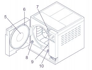
5) Круглая дверь.
6) Прокладка.
7) Бактериологический фильтр.
 Патрубок для слива отработанной воды.
9) Закрывающий механизм с электромагнитным стержнем и внутренним микровыключателем безопасности.
10) Патрубок для слива чистой воды.
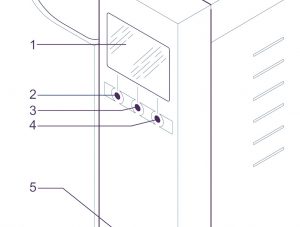
Устройства на задней панели
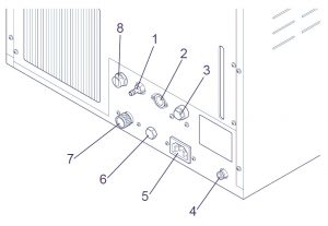
1) Выпускное отверстие при переполнении.
2) Электрический интерфейс деионизатора.
3) Предохранительный термостат (только для euronda e9 MED, начиная с № серии EGO090101 18 литров и EGP090081 24 литра).
4) Патрубок для слива воды дегазатора.
5) Розетка питания.
6) Гидравлическое соединение деионизатора.
7) Предохранительный клапан.
Патрубок для слива отработанной воды.
Верхние элементы
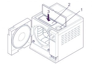
1) Клапан ручной заливки дистиллированной воды.
2) Отделение для хранения предметов.
3) Бак, расположенный внутри устройства, под отделением для хранения предметов.
Описание панели управления евронда е9
1) Графический ЖК-дисплей (320×240 точек). Включает линейку управления, всегда находящуюся на экране, и напрямую связанную с тремя кнопками под линейкой.
2,3,4) Кнопки выбора и передвижения. Эти кнопки имеют не одну функцию, а зависят от линейки управления на экране (1).
5) Встроенный принтер.
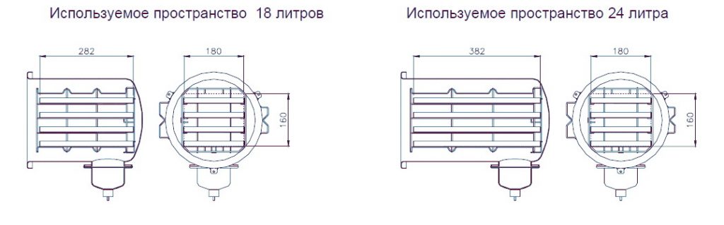
Автоклав euronda e9 размеры и вес
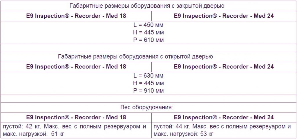
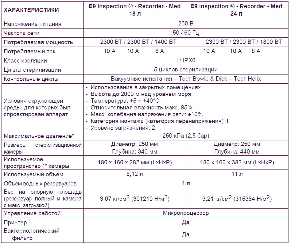
Автоклав euronda e9 технические характеристики
Euronda e9 размер камеры
Внутренний размер камеры стерилизации, доступный для стерилизации материалов.
Встроенный принтер euronda e9
Встроенный принтер для моделей euronda e9 inspection и euronda e9 med
Автоклавы euronda e9 med и euronda e9 inspection настроен таким образом, чтобы данные о продолжающемся процессе стерилизации всегда распечатывались вместе с типом выбранного цикла стерилизации, фазой цикла, значениями температуры и давления, временными интервалами и общей продолжительностью в минутах. После завершения каждого цикла, принтер также распечатывает итоговый отчет о результате цикла и общей продолжительности, независимо от того, удачно ли прошел цикл или нет, и независимо от того, был ли он прекращен оператором или был подан сигнал тревоги. Функция печати итогового отчета может быть отключена по желанию
- Принтер работает только при условии наличия в нем заправленной бумаги.
- Если не поместить рулон бумаги, принтер не работает.
- Зеленый светодиод POWER, имеющийся на принтере, всегда горит, когда принтер работает.
- Красный светодиод ERROR, имеющийся на принтере, горит, когда есть проблема, например, закончилась бумага, крышка закрыта неверно и т д.
- Кнопка FEED, имеющаяся на принтере, служит для протягивания бумаги.
- Нажать один раз на кнопку для продвижения вперед бумаги на одну строку.
- Можно держать кнопку нажатой для постоянного продвижения вперед бумаги.
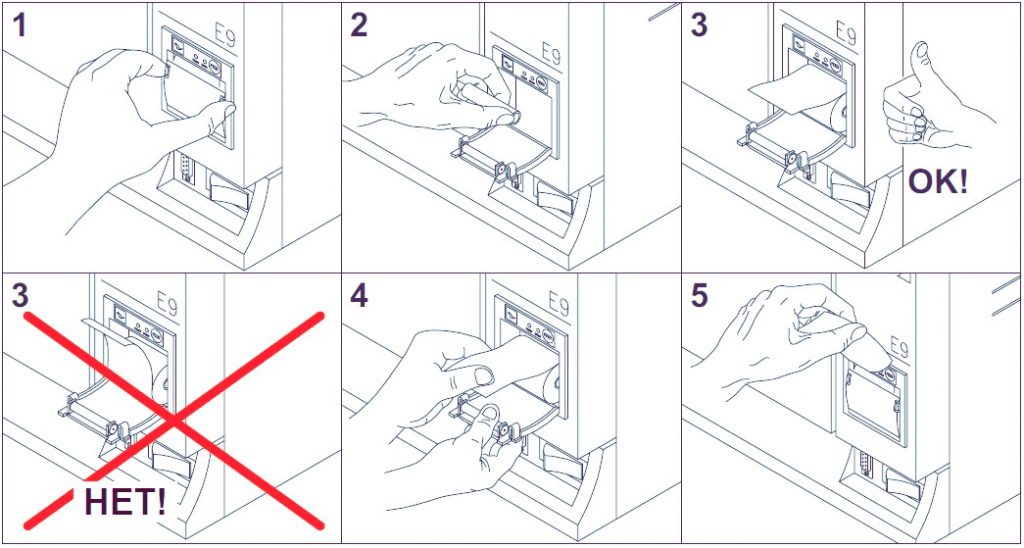
Для заправки нового рулона бумаги:
- Откройте крышку бумажного рулона, придерживая обе стороны пальцами и немного потянув ее на себя.
- Выньте использованный рулон.
- Вставьте новый рулон бумаги, как показано на рисунке; убедитесь, что бумага разматывается в нужном направлении.
- Вытяните наружу небольшой край бумаги и закройте крышку.
- Оторвите лишнюю бумагу.
Используйте рулоны с термобумагой со следующими характеристиками: ширина: 57 — 58 мм, макс. диаметр: 40 мм
Встроенный принтер для модели euronda e9 recorder
Автоклав euronda E9 recorder оборудован встроенным термическим принтером на передней панели и выдает наклейки для идентификации пакетов. Оборудование настроено таким образом, чтобы при положительном результате цикла, распечатывались данные о номере серии автоклава, номере цикла стерилизации, операторе, дате стерилизации и дате срока годности стерилизации (выбирается оператором). Количество этикеток выбирается оператором перед запуском цикла. Помимо количества этикеток, выбранного оператором, автоклав всегда выдает конечную обобщающую этикетку об изменении состояния.
Если цикл стерилизации прошел с отрицательным результатом, принтер выдает обобщающую этикетку о том, что изменение состояния не произошло. Принтер работает только при условии наличия в нем заправленной бумаги.
Для заправки нового рулона бумаги:
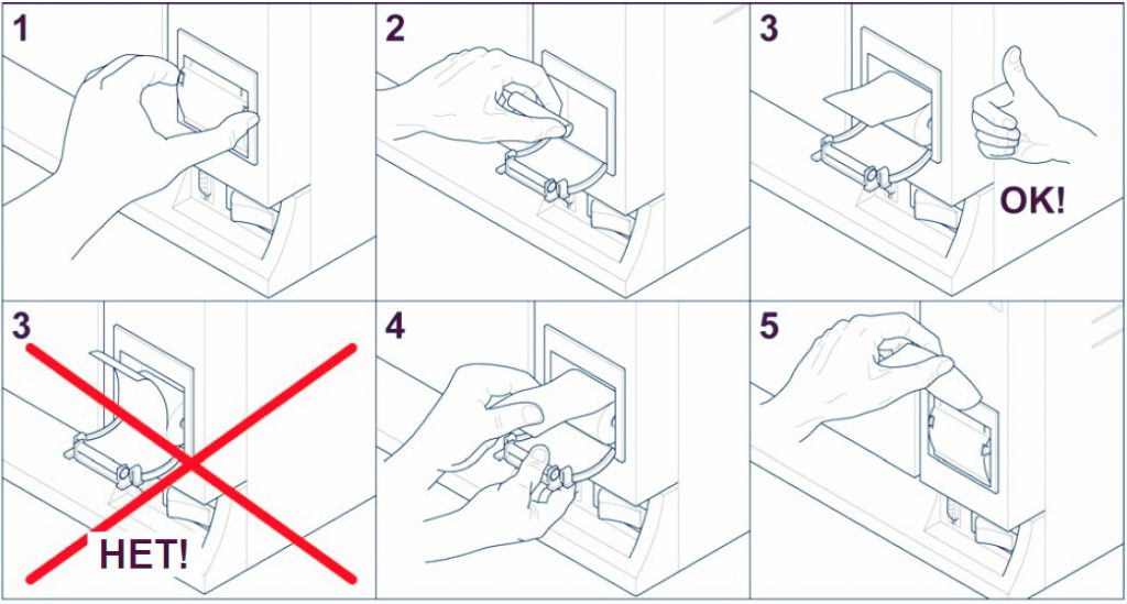
- Откройте крышку бумажного рулона, придерживая обе стороны пальцами и немного потянув ее на себя.
- Выньте использованный рулон.
- Вставьте новый рулон бумаги, так, чтобы боковые суппорты с держателем рулона принтера совпали с самой трубкой держателя рулона; убедитесь, что бумага разматывается в направлении сверху вниз, а не наоборот.
- Вытяните наружу небольшой край бумаги и закройте крышку.
- Оторвите лишнюю бумагу.
Автоклав euronda e9 техническое обслуживание
Как и вся медицинская техника, данный аппарат должен использоваться надлежащим образом, нуждается в регулярном ТО. Это обеспечит длительную эксплуатацию аппарата, безопасность и эффективность оборудования.
Чтобы предупредить возникновение потенциально опасных для оператора ситуаций, техническая служба должна осуществлять регулярное техническое обслуживание и проверки аппарата.
- Чтобы поддерживать оборудование в хорошем рабочем состоянии, периодически протирайте все наружные части мягкой влажной тканью, смоченной в нейтральном моющем средстве (не используйте коррозийные или абразивные средства).
- Не используйте обычные грубые ткани или металлические (или абразивные) щетки для очистки металлов.
- Перед началом каждого цикла, тщательно протирайте влажной тряпкой прокладки люка.
- Образование пятен белого цвета на дне камеры указывает на то, что используемая деминерализованная вода плохого качества.
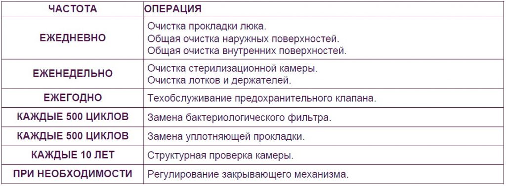
Периодичность технического обслуживания
Скачать инструкцию на автоклав euronda e9
Скачать инструкцию и другую документацию на автоклав euronda e9 можно здесь.
Руководство пользователя ( user manual ) на русском языке автоклав euronda e9 скачать.
Сервисная инструкция ( service manual ) на английском языке автоклав euronda e9 скачать.
Регистрационное удостоверение автоклав euronda e9 скачать.
Декларация о соответствии автоклав евронда е9 скачать.
Так же смотрите автоклав MELAG MELAtronic 23, 17, 15.