Есть станок с системой Fanuc 0MC, 4 оси. При включении отображается 401 alarm и ЧПУ уходит в режим not ready. При этом не включается основной контактор (МСС), но индикаторах блоков приводов светится «—«, ошибок нет.
Что было проделано для локализации неисправности:
1) Проверены все концевые и провода концевых — ОК
2) Проверена цепь кнопки экстренной остановки — ОК
3) Проверен сигнал MCCOFF на интерфейсе JX1B блока питания (power supply module или PSM) — при включении станка сигнал как и положено сменяется с high на low.
4) При этом внутри PSM должно срабатывать реле, подающее питание на катушку MCC. Реле не срабатывает, питание на катушку не подаётся.
5) Был вскрыт PSM и определено что реле должен замыкать транзистор. Транзистор на первый взгляд исправен, но на его базу не приходит напряжение. База соединена с одним из выводов большого чипа с логотипом Fanuc.
6) С другой стороны прохождение сигнала MCCOFF с разъёма JX1B отследить не удалось, т.к. плата сложная и многослойная.
7) Скорее всего проблема где-то в логике PSM. Документации со схемами по нему естественно нет, есть только мануал с довольно общим описанием — http://support.ge-ip.com/support/resources/sites/GE_FANUC_SUPPORT/content/live/DOCUMENT/0/DO889/en_US/GFZ65162E03.pdf
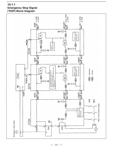
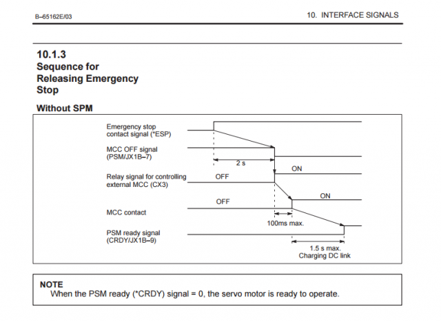
Прикрепил скрины страниц из мануала, на 355 странице мануала показана схема прохождения сигналов. На 357 их последовательность:
1) При отпускании кнопки emerency stop сигнал ESP сменяется с низкого уровня на высокий. Это работает
2) Сигнал MCCOFF собирается от всех блоков приводов и шпинделя, и должен иметь низкий уровень. Это тоже работает, уровень MCCOFF низкий.
3) PSM при изменении сигнала MCCOFF с высокого уровня на низкий должен замыкать реле и подавать питание на MCC. Этого не происходит, отчего и имеем ошибку.
4) PSM при включении MCC должен отчитаться о готовности — отобразить на своём индикаторе «00» и выдать сигнал готовности остальным приводам. Этого естественно тоже нет.
Пробовали принудительно замыкать контакты реле — MCC включается, но обмануть логику PSM не получилось, т.к. он всё-равно не переходит в режим готовности. Дальше обманывать логику (подавать принудительный сигнал готовности PSM) не решились, т.к. это не безопасно.
PSM вот такой — http://www.ebay.com/itm/FANUC-A06B-6087-H115-Power-Supply-Module-/221880313683?hash=item33a918e753
Плата логики, которая стоит внутри PSM такая — A16B-2202-0421 http://www.easycnc.net/fanuc/pcb/a16b-2202-0421.html
Купить новую плату конечно самый очевидный вариант, но нет 100% уверенности что проблема в ней.
Есть ли на территории РФ или ближнего зарубежья специалисты по Fanuc, которые смогли бы продиагностировать плату или весь блок PSM, либо посоветовать как лучше быть в такой ситуации? Возможно есть ещё что-то, что было нами упущено во время поиска неисправности?
-
#1
I am getting an alarm sometimes;-
401 servo alarm X axis VRDY OFF
and
401 servo alarm Z axis VRDY OFF
When they come up, I have to shut up and re start
to clear them.
anybody could hint why these come up?
-
#2
When does the alarm appear? Start up? Idle? While in cut? Will the axis still move?
-
#3
when the come up
unpredictable!
ususall when referencing or at power on or startup of the machine.
they will not go away. You have to power off and power on.
Alfonzo, just in case you know, I have changed Parameter 40 on the OT machines bit Zero to 1.
This will change the way programs are displayed. Mine I do a number and the description of the program in parenhesis.
the fanuc 18T control does not have this parameter or better still, have not managed to find it. I am sure that this control can show the programs this way too.
any leads?
-
#4
One possibility is a bad cable on one of the axis drives,, we had a similar problem with a servo alarm that seemed to happen unpredicably,,the wires actually looked ok but they were broken inside the insulation,, Keep an eye if the alarm happens in one area of travel only, and then move the cables to try and get the same alarm,,

Ox
Diamond
-
#6
OK — I’m cornfused …. is this on an «0» or «18»?
—-
Think Snow Eh!
Ox
-
#7
The control is an 18T Fanuc.
The cables are in perfect condition. New machine with just a few hundred hours of work.
but it was idle for some years in storage. maybe the batteries-? somebody mentioned?
-
#8
Alfonzo, just in case you know, I have changed Parameter 40 on the OT machines bit Zero to 1.
This will change the way programs are displayed. Mine I do a number and the description of the program in parenhesis.
the fanuc 18T control does not have this parameter or better still, have not managed to find it. I am sure that this control can show the programs this way too.
any leads?
I don’t have any machines with 18T, only 18MC.
On those:
3107.0 toggles program number only/ number and name.
3107.4 sorts programs by number/registration.
3107.5 displays G code menu.
Seems to me that you need to buy a number of (GE)Fanuc manuals. I have found that the manuals from GEFanuc cost 25% less than from Fanuc. Of course that’s in the USA. May be cheaper for you from a European source.
About the 401 error. Since the machine was stored for a long time, the contacts in the various relays may be slightly oxidized and not allowing current to pass thru normally. I have one machine that regularly gives an error message on start up because of this. Pop the relay lever and the message goes away.
Also, pain in the ass, but disconnect and reconnect every cable connection related to axi control just to make sure there are good connections.
If you can figure out where to look in the ladder display, you can see the location where the circuit is not right. Have a print of the ladder from the MTB?? Sure could help you find problem.
-
#9
Alphonso, thanks for the tip. On the 18T I changed bit zero to 1 and there it was.
I have heaps of manuals here but the 18T came with some manuals missing.
contacted Gildemeister and asked them what a new machine would be issued with. Sure, I had the Fanuc manuals missing. So they said, I pumped up 500 euros and they sent me about six books from Fanuc. will look this place you siad.
Thanks for the tips…
|
|
Ремонт сервопривода Fanuc Alfa и Beta series

Сервисный центр «Кернел» предлагает выполнить качественный ремонт сервопривода Fanuc Alfa и Beta series в на компонентном уровне в максимально сжатые сроки.
Сервопривода относятся к сложной промышленной электронике именно поэтому ремонтом серводрайверов Fanuc Alfa и Beta series, впрочем, как и сервоприводов других производителей должны заниматься специалисты, имеющие не только высшее техническое образование, но и солидный опыт в ремонте подобной промышленной электроники.
Также для восстановления подобного промышленного оборудования понадобится хорошая материально-техническая база. При выполнении этих условий шансы на успешный ремонт сервопривода Fanuc Alfa и Beta series возрастают в геометрической прогрессии.
Именно поэтому за ремонтом сервоприводов Fanuc Alfa и Beta series или другого производителя лучше всего обращаться в специализированный сервисный центр, который отвечает всем техническим требованиям, такой как Кернел.
Наш цент имеет отличную материально-техническую ремонтную базу, а за время существования с 2002 года специалисты компании накопили бесценный опыт в том числе опыт в ремонте сервоприводов Fanuc Alfa и Beta series.
Инженеры сервисного центра выполняют качественный ремонт сервоприводов Fanuc всех серий, когда-либо выпускаемых компанией.
| Серия | Тип сервоусилителя |
|---|---|
|
Fanuc Alfa series Fanuc Beta series |
A06B-6111-H037#H550; A06B-6111-H030#H570/P; A06B-6111-H030#H553; A06B-6111-H030#H550#P; A06B-6111-H030#H550#C; A06B-6111-H026#H570; A06B-6111-H026#H553; A06B-6111-H026#H550#P; A06B-6111-H026#H550#C; A06B-6111-H022#H570/P; A06B-6111-H022#H553; A06B-6111-H022#H550/C; A06B-6164-H244#H580; A06B-6164-H312#H580; A06B-6164-H332#H580; A06B-6165-H201#H560; A06B-6165-H202#H560; A06B-6164-H201#H580; A06B-6165-H311#H560; A06B-6165-H312#H560; A06B-6165-H333#H560; A06B-6165-H343#H560; A06B-6166-H201; A06B-6166-H201#A; A06B-6058-H225; A06B-6200-H011; A06B-6089-H104; A06B-6117-H105; A06B-6114-H205; A06B-6114-H109; A06B-6166-H203; A06B-6050-H103; A06B-6127-H209; A06B-6102-H206#H520; A06B-6121-H006#H550; A06B-6140-H037; A06B-6134-H303#A; A06B-6088-H215; A06B-6082-H222; A06B-6064-H230; A06B-6044-H017; A06B-6064-H201#H520; A06B-6088-H245; A06B-6088-H222; A06B-6057-H204; A06B-6089-H207; A06B-6052-H004; A06B-6117-H208; A06B-6082-H215#H511; A06B-6082-H215#H510; A06B-6082-H211#H512; A06B-6082-H211#H511/EM; A06B-6082-H211#H510; A06B-6082-H206#H511; A06B-6082-H206#H510/EM; A06B-6082-H206#H510; A06B-6082-H202#H512; A06B-6082-H202#H511; A06B-6082-H202#H510; A06B-6080-H307; A06B-6059-H215#H545; A06B-6059-H215#H515; A06B-6059-H212#H759; A06B-6059-H212#H758; A06B-6059-H212#H757; A06B-6059-H212#H713; A06B-6059-H212#H712; A06B-6059-H212#H711; A06B-6059-H212#H611; A06B-6059-H212#H610; A06B-6059-H212#H601; A06B-6059-H212#H590; A06B-6045-H006; A06B-6045-H005; A06B-6045-H002; A06B-6045-H001; A06B-6045-C009; A06B-6045-C006; A06B-6045-C005; A06B-6044-H742; A06B-6044-H736; A06B-6044-H725; A06B-6044-H722; A06B-6044-H712 |
В данной таблице присутствуют далеко не все сервоприводы Fanuc Alfa и Beta series ремонт которых предлагает наш сервисный центр.
Особенности ремонта сервопривода Fanuc Alfa и Beta series
 Ремонт сервопривода Fanuc Alfa и Beta series имеет ряд индивидуальных особенностей, это связано с конструктивными особенностями сервоприводов. По аналогии частотными преобразователями, сервопривод состоит из двух частей, это:
- Аппаратная часть;
- Программная часть.
В первую очередь ремонтируется аппаратная часть промышленного сервопривода. После глубокой диагностики неисправного блока выявляются все неисправные компоненты, которые в последствии заменяются на оригинальные запасные части (по возможности), в случае если сервопривод уже давно снят с производства и найти оригинальные запчасти просто невозможно они заменяются на аналоги.
Данный вид ремонта называется компонентным. От других видов его отличает две немаловажные вещи.
- Значительное удешевление ремонта;
- Существенное сокращение времени ремонта.
По завершении ремонта аппаратной части сервопривода наступает очередь программной. В зависимости от серии выбирается программный продукт и зашивается в блок.
Заключительный этап ремонта сервопривода Fanuc Alfa и Beta series в это проверка на специализированном стенде, без нагрузки и с нагрузкой максимально приближенна к реальным условиям эксплуатации.
Ошибки сервоприводов Fanuc Alfa и Beta series
 В процессе работы выходит из строя даже самое надежное промышленное оборудование. В данной статье мы приведем ошибки сервоприводов Fanuc, а точнее Fanuc Alfa и Beta series. Привода в наше время, нашли широкое применение абсолютно во всех сферах промышленности, управляя как мини моторами в оргтехнике, так и гигантскими двигателями в горнодобывающей промышленности.
Для простоты общения со столь сложной электроникой все сервопривода оснащены небольшими дисплеями с помощью которых выводятся информационные сообщения с кодами ошибок, расшифровав которые можно сразу же узнать причину ее возникновения. Если учесть распространенность данной промышленной электроники, то появляется острая нужда в расшифровке кодов ошибок сервопривода. В этой статье мы рассмотрим одного из самых известных производителей промышленной электроники имеющему уважение во всем мире, Fanuc и севрво усилители Alfa и Beta series.
Существует несколько видов ошибок, некоторые из них можно устранить автоматически, а некоторые возможно исправить только, обратившись в специализированный сервисный центр. В таблицах ниже приведены коды ошибок сервоприводов Fanuc Alfa и Beta series и их расшифровка.
Fanuc Servo Amplifier Beta is 6130 сигналы тревоги (ошибки)
| Сигнал тревоги | Оисание |
|---|---|
|
SV0027 or 027 |
Неверная настройка параметров цифрового сервопривода |
|
SV0361 or 361 |
Фазовая ошибка импульсного кодера (встроенная) |
|
SV0364 or 364 |
Мягкая фазовая сигнализация (встроенная) |
|
SV0365 or 365 |
Светодиод ошибки (встроенный) |
|
SV0366 or 366 |
Импульсная ошибка (встроенная) |
|
SV0367 or 367 |
Ошибка подсчета (встроенная) |
|
SV0368 or 368 |
Ошибка серийных данных (встроенная) |
|
SV0369 or 369 |
Ошибка передачи данных (встроенная) |
|
SV0380 or 380 |
Ошибка светодиода (отдельно) |
|
SV0381 or 381 |
Фазовая ошибка импульсного кодера (отдельно) |
|
SV0382 or 382 |
Ошибка подсчета (отдельно) |
|
SV0383 or 383 |
Ошибка импульса (отдельно) |
|
SV0384 or 384 |
Мягкая фазовая сигнализация (отдельно) |
|
SV0385 or 385 |
Ошибка серийных данных (отдельно) |
|
SV0386 or 386 |
Ошибка передачи данных (отдельно) |
|
SV0387 or 387 |
Ошибка датчика (отдельно) |
|
SV0417 or 417 |
Неверный параметр |
|
SV0421 or 421 |
Чрезмерная полуполная ошибка |
|
SV0430 or 430 |
Серводвигатель перегревается |
|
SV0432 or 432 |
Преобразователь: управление пониженным напряжением питания |
|
SV0433 or 433 |
Преобразователь: пониженное напряжение в звене постоянного тока |
|
SV0436 or 436 |
Мягкая термальная (OVC) |
|
SV0438 or 438 |
Инвертор: аварийный сигнал тока двигателя |
|
SV0439 or 439 |
Преобразователь: перенапряжение в звене постоянного тока |
|
SV0440 or 440 |
Преобразователь: Чрезмерная мощность торможения |
|
SV0441 or 441 |
Текущая ошибка смещения |
|
SV0444 or 444 |
Инвертор: внутренний охлаждающий вентилятор остановлен или неисправна цепь |
|
SV0445 or 445 |
Сигнализация мягкого отключения |
|
SV0447 or 447 |
Сигнализация жесткого отключения (отдельно) |
|
SV0448 or 448 |
Сигнализация несоответствия обратной связи |
|
SV0449 or 449 |
Инвертор: тревога IPM |
|
SV0453 or 453 |
Сигнализация мягкого отключения (α Pulsecoder) |
|
SV0601 or 601 |
Инвертор: вентилятор охлаждения радиатора остановился |
|
SV0603 or 603 |
Инвертор: Аварийный сигнал IPM (OH) |
Fanuc Servo Amplifier 400 Коды аварийных сигналов
| Код ошибки | Сообщение | Описание |
|---|---|---|
|
400 |
SERVO ALARM: n–TH AXIS OVERLOAD |
Сигнал перегрузки оси n (оси 1–8) включен. Подробную информацию см. на диагностическом дисплее № 201, 720 или 721. |
|
401 |
SERVO ALARM: n–TH AXIS VRDY OFF |
Сработал сигнал ГОТОВНОСТИ (DRDY) сервоусилителя n-й оси (оси 1–8). |
|
402 |
SERVO ALARM 3, 4TH AXIS OVERLOAD |
3-осевой, 4-осевой сигнал перегрузки включен. Подробную информацию см. на диагностическом дисплее 722 или 723. |
|
404 |
SERVO ALARM: n–TH AXIS VRDY ON |
Несмотря на то, что сигнал ГОТОВНОСТИ (MCON) оси n (оси 1–8) был отключен, сигнал ГОТОВНОСТИ сервоусилителя (DRDY) все еще включен. Или, когда питание было включено, DRDY включился, хотя MCON был выключен. Убедитесь, что интерфейсный модуль сервопривода и сервоусилитель подключены. |
|
405 |
SERVO ALARM: (ZERO POINT RETURN FAULT) |
Ошибка системы управления положением. Из-за ошибки ЧПУ или сервосистемы при возврате в референтную позицию существует вероятность того, что возврат в референтную позицию не может быть выполнен правильно. Повторите попытку из ручного возврата в референтную позицию. |
|
407 |
SERVO ALARM: EXCESS ERROR |
Разница в отклонении положения синхронной оси превысила установленное значение. |
|
409 |
SERVO ALARM: n AXIS TORQUE ALM |
Обнаружена аномальная нагрузка серводвигателя. Кроме того, в режиме Cs была обнаружена аномальная нагрузка на двигатель шпинделя. |
|
410 |
SERVO ALARM: n–TH AXIS – EXCESS ERROR |
Значение отклонения положения при остановке n–й оси (оси 1–8) больше установленного значения. |
|
411 |
SERVO ALARM: n–TH AXIS – EXCESS ERROR |
Значение отклонения положения при перемещении n–й оси (оси 1–8) больше заданного значения. |
|
413 |
SERVO ALARM: n–th AXIS – LSI OVERFLOW |
Содержимое регистра ошибок для n-й оси (оси 1–8) превышало 231 степень. Эта ошибка обычно возникает в результате неправильно заданных параметров. |
|
414 |
SERVO ALARM: n–TH AXIS – DETECTION RELATED ERROR |
Неисправность цифровой сервосистемы N–й оси (оси 1–8). Подробности см. в диагностическом дисплее № 200 и № 204. Также посмотрите на сервоусилитель для кода тревоги. |
|
415 |
SERVO ALARM: n–TH AXIS – EXCESS SHIFT |
Была предпринята попытка задать скорость выше 511875 ед/с по оси n–th (оси 1–8). Эта ошибка возникает в результате неправильно настроенного CMR. |
|
416 |
SERVO ALARM: n–TH AXIS – DISCONNECTION |
Неисправность системы определения положения импульсного шифратора n–й оси (оси 1–8) (сигнализация отключения). Подробности см. на дисплее диагностики № 201. |
|
417 |
SERVO ALARM: n–TH AXIS – PARAMETER INCORRECT |
Этот аварийный сигнал возникает, когда n–я ось (ось 1–8) находится в одном из состояний, перечисленных ниже. (Аварийный сигнал цифровой сервосистемы)
Если вы хотите использовать этот усилитель, сбросьте функциональный бит 2209#4 на 0. Если вы хотите использовать функцию предотвращения тревоги HC, используйте усилитель, который ее поддерживает. |
|
420 |
SERVO ALARM: n AXIS SYNC TORQUE (M series) |
При простом синхронном управлении разница между командами крутящего момента для ведущей и ведомой осей превысила значение, установленное в параметре № 2031. |
|
421 |
SERVO ALARM: n AXIS EXCESS ER (D) |
Разница между ошибками в полузамкнутом контуре и замкнутом контуре стала чрезмерной во время двойной обратной связи по положению. Проверьте значения коэффициентов преобразования двойной позиции в параметрах № 2078 и 2079. |
|
422 |
SERVO ALARM: n AXIS |
При управлении крутящим моментом управления осью PMC превышена заданная допустимая скорость. |
|
423 |
SERVO ALARM: n AXIS |
При управлении крутящим моментом управления осями PMC было превышено заданное параметром допустимое совокупное расстояние перемещения. |
|
430 |
n AXIS : SV. MOTOR OVERHEAT |
Произошел перегрев серводвигателя. |
|
431 |
n AXIS : CNV. OVERLOAD |
|
|
432 |
n AXIS : CNV. LOWVOLT CON. |
|
|
434 |
n AXIS : INV. LOWVOLT CONTROL |
SVM: Напряжение питания системы управления упало. |
|
435 |
n AXIS : INV. LOWVOLT DC LINK |
SVM: Напряжение в звене постоянного тока упало. |
|
436 |
n AXIS : SOFTTHERMAL (OVC) |
Программное обеспечение цифрового сервопривода обнаружило мягкое тепловое состояние (OVC). |
|
437 |
n AXIS : CNV. OVERCURRENT POWER |
PSM: Перегрузка по току во входную цепь. |
|
438 |
n AXIS : INV. ABNORMAL CURRENT |
|
|
439 |
n AXIS : CNV. OVERVOLT POWER |
|
|
440 |
n AXIS : CNV. EX DECELERATION POWER |
|
|
441 |
n AXIS : ABNORMAL CURRENT OFFSET |
Программное обеспечение цифрового сервопривода обнаружило неисправность в цепи обнаружения тока двигателя. |
|
442 |
n AXIS : CNV. CHARGE FAILURE |
|
|
443 |
n AXIS : CNV. COOLING FAN FAILURE |
|
|
444 |
n AXIS : INV. COOLING FAN FAILURE |
SVM: Отказ внутреннего вентилятора охлаждения. |
|
445 |
n AXIS : SOFT DISCONNECT ALARM |
Программное обеспечение цифрового сервопривода обнаружило обрыв провода в импульсном кодере. |
|
446 |
n AXIS : HARD DISCONNECT ALARM |
Обрыв провода во встроенном импульсном кодере был обнаружен аппаратно. |
|
447 |
n AXIS : HARD DISCONNECT (EXT) |
Обрыв провода в отдельном детекторе был обнаружен аппаратно. |
|
448 |
n AXIS : UNMATCHED FEEDBACK ALARM |
Знак данных обратной связи от встроенного импульсного кодера отличается от знака данных обратной связи от отдельного детектора. |
|
449 |
n AXIS : INV. IPM ALARM |
|
|
453 |
n AXIS : SPC SOFT DISCONNECT ALARM |
Программная сигнализация об отключении импульсного кодера α. Отключите питание ЧПУ, затем отсоедините и вставьте кабель импульсного кодера. Если этот аварийный сигнал появляется снова, замените импульсный шифратор. |
|
456 |
ILLEGAL CURRENT LOOP |
Текущие настройки цикла управления (параметр № 2004, бит 0 параметра № 2003 и бит 0 параметра № 2013) неверны. Возможные проблемы следующие.
|
|
457 |
ILLEGAL HI HRV (250US) |
Использование высокоскоростного HRV указано, хотя текущий цикл управления составляет 200 мкс. |
|
458 |
CURRENT LOOP ERROR |
Текущая настройка цикла управления не соответствует фактическому текущему циклу управления. |
|
459 |
HI HRV SETTING ERROR |
Из двух осей, имеющих соседние номера сервоосей (параметр № 1023), нечетные и четные номера, высокоскоростное управление HRV может выполняться для одной оси, а не для другой. |
|
460 |
n AXIS : FSSB DISCONNECT |
Связь с ФСБ внезапно прервалась. Возможные причины следующие:
|
|
461 |
n AXIS : ILLEGAL AMP INTERFACE |
Оси 2-х осевого усилителя были отнесены к интерфейсу быстрого типа. |
|
462 |
n AXIS : SEND CNC DATA FAILED |
Из-за ошибки связи FSSB ведомое устройство не могло получить правильные данные. |
|
463 |
n AXIS : SEND SLAVE DATA FAILED |
Из-за ошибки связи FSSB ведомое устройство не могло получить правильные данные. |
|
464 |
n AXIS : WRITE ID DATA FAILED |
Была предпринята попытка записать информацию об обслуживании на экране обслуживания усилителя, но она не удалась. |
|
465 |
n AXIS : READ ID DATA FAILED |
При включении питания исходная идентификационная информация усилителя не может быть считана. |
|
466 |
n AXIS : MOTOR/AMP COMBINATION |
Максимальный номинальный ток усилителя не соответствует номинальному току двигателя. |
|
467 |
n AXIS : ILLEGAL SETTING OF AXIS |
Функция сервопривода для следующего не была включена, когда ось, занимающая один DSP (соответствующий двум обычным осям), указана на экране настройки оси.
|
|
468 |
HI HRV SETTING ERROR(AMP) |
Использование высокоскоростной HRV указано для управляемой оси усилителя, которая не поддерживает высокоскоростную HRV. |
Для более длительной безаварийной работы промышленного оборудования должны соблюдаться все рекомендации, изложенные в инструкции по монтажу и настройке сервопривода.
Сервопривод Fanuc Alfa и Beta series, скачать инструкции по эксплуатации
Ниже вы можете скачать руководства по эксплуатации сервоприводов Fanuc Alfa и Beta series для практически всех серий, когда-либо выпущенных данным производителем.
Преимущество ремонта сервоприводов в нашем сервисном центре

- Предварительный осмотр на возможность восстановления бесплатный;
- Мы производим ремонт сервопривода Fanuc Alfa и Beta series в на компонентном уровне (экономия бюджета и времени)
- При ремонте ни каких конструктивных изменений не вносим;
- Ремонт блоков с применением оригинальных запасных частей (по возможности).
- Вы платите исключительно за результат — работающий сервопривод;
- Гарантия на ремонт сервопривода Fanuc Alfa и Beta series и запасные части, замененные в процессе ремонта 6 месяцев;
- Сроки ремонта варьируются от 5 до 15 рабочих дней;
За два десятилетия существования сервисного центра нашими специалистами были успешно проведены тысячи подобных ремонтов с каждым разом поднимая квалификацию наших инженеров.В случае выхода из строя промышленного сервопривода на вашем производстве либо появились проблемы с приводом, которые вы не можете решить самостоятельно, мы всегда рады вам помочь. Специалисты нашего сервисного центра в минимальные сроки проведут глубокую диагностику и последующий ремонт сервопривода Fanuc Alfa и Beta series в .
Схемы подключения серво привода Fanuc Alfa series
В некоторых случает может понадобится схема подключения сервоприводов, ниже мы показаны схемы сервопривода Fanuc Alfa series
|
Блок-схема подключения сервопривода Fanuc Alfa series SVMl-240,360 — вариант (А) |
Блок-схема подключения сервопривода Fanuc Alfa series SVMl-240,360 — вариант (В) |
|
|

|

Оставить заявку на ремонт сервопривода Fanuc Alfa и Beta series
У вас есть проблемы с приводом? Вам нужен срочный ремонт, сброс ошибок или программирование и настройка? Оставьте заявку на ремонт сервопривода Fanuc Alfa и Beta series в воспользовавшись одноименной кнопкой на сайте либо обратитесь к нашим менеджерам. Связаться с ними можно несколькими способами:

- Заказав обратный звонок (кнопка в правом нижнем углу сайта)
- Посредством чата (кнопка расположена с левой стороны сайта)
- Позвонив по номеру телефона: +7(8482) 79-78-54; +7(917) 121-53-01
- Написав на электронную почту: 89171215301@mail.ru
- В начало статьи
Вот далеко не полный список производителей промышленного оборудования, ремонт которого производит наша компания.
-
07-26-2008, 12:19 PM
#1

Registered
Eveything was OK with machine, until we have moved it from place to place, just for one meter, by hand, carefully, and cleaned (washer) it, also carefully.
Now when I turn it on (main pow, nc control) and i pull out emergency stop, this alarm appears
401 SERVO ALARM: (VRDY OFF)
And I can’t get rid of it, I push reset, it appears again, pull in/out EM STOP, alarm appears again.
Machine is not movable (nor in handle mode).
I have tryed to turn it off and on for several times, but no progress.
And on servo amplifiers there is no alarm code, just » — » as not ready.I have red lot about this alarm, but it could be anything (wires, relays, amplifier, servo brushes, dirty servo…..?)
And read again my first sentance, it may be important for finding solution.
-
07-26-2008, 12:46 PM
#2
Registered
You may have a limit switch that has stuck open or become shorted by the washing process. Look for limit switches on each axis (in both + and — direction). There are frequently TWO limit switches in each direction. One limit switch simply causes an Overtravel (OT) alarm, and you can then jog in the oposite direction to move off the switch. The second switch is an «Extreme» overtravel switch, and it is designed to protect the ballscrews and stop the servo positively if the first switch should fail, or if the CNC should ignore the OT switch. On some machines, that switch is tied to the 24v E-stop circuit, which will simply make the machine come up «NOT READY». Other machines, however, use the 100vac circuit to enable the servo contactors for that same purpose. If your machine is wired like this, and one of these switches was stuck on, filled with water, or otherwise defective, you will get your 401 servo alarm. Also look for damaged cables from these switches to the CNC, and inspect any connectors you may find along these cables. These extreme overtravel switches are usually wired as «normally closed» and are in series, so actuating any one of them breaks the circuit and shuts down all the servos.
-
07-26-2008, 01:08 PM
#3
Registered
Thanks for help, machine was in «middle» position, far from limit switches.
Actually I have just solved the problem
Silly me, we have reconected main power input to tramsformer, and one wire (one phase) was not tightened well, and there were just two phases connected.
(nuts)
Thanx
-
08-03-2008, 09:03 AM
#4
Member
Hi all.
I have the same problem: The alarm » 401″ appear on screen when power on, I checked all wires, and can not find the reason. Pls. help me to fix this problem.
Thanks
-
08-04-2008, 01:52 AM
#5
Member
-
08-05-2008, 03:09 AM
#6
Registered
you have to check the power supply for the axis card it has some pines where you can test 25v 10v -25v or something like that maybe you transformator is broken
-
08-05-2008, 03:35 AM
#7
Member
Dear robertox
Thanks for your reply, but I checked all the wires and voltage, all it are normally( the machine was work fine before). Is there some thing else?
Did you know how to turn on F148.6, it will turn on Y51.2 then show up the procedure.
Thanks
-
08-05-2008, 03:46 AM
#8
Registered
Remove the cap from each axis motors and remove any brush dust (be careful, it’s probably toxic!) and inspect/clean the commutator. While you’re at it, check the brush length/condition and replace as required.
I was getting persistant 401 errors on my mill and cleaning out the X and Y motors got rid of them almost completely. I still get the occasional 401 error, but I can usually clear it with one off/on cycle and it’s probably because I didn’t clean out the Z motor (which is buried in the machine casting).
-
08-05-2008, 04:21 AM
#9
Member
Dear Scirchen
Thanks for your reply, I’ll check it tonorow.
-
08-06-2008, 03:52 AM
#10
Member
Dear skirchen
I checked already, this is AC motor, do you mean I need to check at encoder? But it’s have no too. Pls. help me. Do you have servo amplifier manual( it’s code AB-1003-O86), if yes, pls. sent it to me( e-mail: namnp2007@gmail.com)
Thanks for your time
-
08-06-2008, 04:11 AM
#11
Registered
Namnp2007,
I’m not 100% sure, but I think that AC motors don’t have brushes, so my fix isn’t going to work for you. There are lot’s of things that it could be; do a google search for «fanuc 401» and you will get lots of results. That’s where I got the idea to clean out the brushes .
Fanuc is a good source for the manuals (http://www.fanuc.co.jp/en/contact/index.htm). Plus, their tech department is usually very good about debugging problems over the phone, even if you bought the machine used. I once had a tech on the phone for over an hour; I was checking things on the machine while he was feeding me instructions.
Chris Kirchen
-
08-06-2008, 04:45 AM
#12
Member
-
08-11-2008, 03:33 PM
#13
Registered
Im geeting the same 401 alarms on my clausing lathe 21i-T control. alarm appears on X, Z, and B axis. Machine has AC motors as well and switches are proxy. othing appears to be stuck to them. Any thoughts or ideas on how i can get this alarm off im all ears
-
08-12-2008, 02:33 AM
#14
Member
Dear hydrospin
Maybe you need to check some out put relay, when power on, you can hear one «click» sound, that indicated the Amplifier start work, at this time, maybe some relay work too( you can find by LED), but in my case, one of them had bad connection, so machine become down and 401 alarm appear.
Hope to help you.
-
08-18-2008, 04:44 AM
#15
Registered
Hello
Dear all
I hope that this file may useful
-
08-18-2008, 05:40 AM
#16
Member
401 VRDY Alarm
Originally Posted by congchipham
Dear all
I hope that this file may useful
Dear congchipham
Thanks for your reply, it’s more usefull for us
-
04-25-2011, 06:48 PM
#17
Registered
Hello gents,
what parameter i have to change to increase and decrease the spindle RPM i have a Fanuc OT-C control
-
12-01-2014, 12:39 PM
#18
Registered
Re: 401 servo alarm (VRDY OFF), at turn on, Fanuc OM SOLVED
Hello
I read carefully this topic.
Don’t find any solution for my «401 VRDY OFF «I have a 0m-C controller and this error appear after 5-10 min from power-on even if the axis is not move.
All the voltage 110V and 220V are OK…The ESTOP circuit are ok…I work with machine only for reference, 5min in program and…401…Can you give some ideas for repair.
Thanks!
-
12-02-2014, 01:31 AM
#19
Member
Re: 401 servo alarm (VRDY OFF), at turn on, Fanuc OM SOLVED
Dear DannyB.
Maybe your amplifier was mailfuntion, you have to change it for double check.
-
05-20-2015, 01:16 PM
#20
Registered
Re: 401 servo alarm (VRDY OFF), at turn on, Fanuc OM SOLVED
Would like to add another solution with error code 401 (fanuc 0M).
Before this error make us to feel sick every day for more than year!!!
On the drive are five relays. Three of them are powered on in parallel.
110V Coil of one of them was burn out. We replaced relay with new one (we used different size relay, original is very rare)
And now our Fanuc works as new!!!
Thanks to everyone (and of course google :-))) who wrote their solution!!!


FANUC CNC machine is an extremely useful tool – but like many tools, it’s susceptible to breaking. Read on to learn common FANUC issues and how to best troubleshoot to solve the problem.
What is the proper method to test a motor for a short?
The proper way to troubleshoot a FANUC motor for a short is to first lock out the machine, remove the cable from the drive, and test all three motor phases to ground with a megohmmeter. This will test both the motor and the cable for problems.
Why am I getting errors when I connect to my FANUC drive’s RS-232 port?
There are a number of explanations for these errors. The RS-323 port is a high-fail component on a FANUC drive as it is very susceptible to electrical surges. However, the RS-232 cable is also another high-fail item. Ensure that you are using a cable that is known to be functional when communicating. Otherwise when you attempt to read-in or punch-out a cable, you will get an 086 alarm that is going to indicate that the cable is incorrect, or that the port has failed.
To test whether the cable or the port has failed, take a known good cable and insert it into the RS-232 port. Next, set your machine up to receive a file. The screen should being to flash “READ”. Next, transmit your file into the machine tool. If the machine continues to flash “READ” (or “LSK” on modern controls) but never receives the file, you have a defective communications port on either the memory board or the master board. These boards or your machine will need to be sent in for repair.
What is an Axis Communications Error?
An Axis Communications Error indicates a communications problem between the motor encoder and the CNC control. This can be caused by the motor encoder itself, the cable going to the encoder, or the axis control card the cable is plugged into.
What is an Excess Error Alarm and why is it caused?
Generally, an Excess Error means that the machine has moved beyond its allowable tolerance. The CNC has told the FANUC servo drive to make a move, the servo drive moves the motor, which in turn moves the encoder. As the machine moves, there will be some deviation. This deviation is known as the Excess. The parameters set how much deviation/excess should be allowed.
These errors can be caused by a variety of problems. For example, a dull tool can caused the axis to be pushed out of position which results in a deviation error. Debris build up can cause deviations while the machine is stopped. Additionally, a failed servo drive can also cause deviation errors.
What is FANUC 401 Servo Alarm?
Alarm 401 is a very generic FANUC alarm. It simply means that the servo’s did not obey. The CNC, which is in charge of the servos, tells the servo drives to turn on and remain on. If for whatever reason the servo drive turns itself off without the permission from the CNC, the CNC will generate a 401 alarm. This alarm will usually occur with other alarms, such as the 414 Alarm.
What is FANUC Servo Alarm 414?
The FANUC Servo Alarm 414 is an alarm issued by the CNC that says a problem has been found in either the servo drive or the feedback system. The alarm will show which axis is causing the problem. To identify the specifics of this alarm, you must go into the CNC diagnostics page. Diagnostics number 200 on the 16th row will indicate what is causing the problem.
What is the difference between a High-Current Alarm and an Over-Current alarm?
A high current is an abnormal current that can be caused by noise. When the system detects this, it will generally shut the machine down and generate a High-Current Alarm. This FANUC alarm code is usually caused by defective servo drive or cooling contamination inside of the motor windings or cable.
An Over-Current Alarm indicates that too much current has flowed through the DC link. This is usually caused by a short in the system, an unplanned contact, a defective transistor module, or dull tooling attempting to make a cut.
Why do I get a Soft Overtravel Alarm when I try to reference a newly installed motor?
When the CNC power down, it remembers its last known position. When you restart the machine, an incremental encoder will ask that the machine be re-positioned. When you try to do a re-reference of the machine tool, and it doesn’t agree with where the last known position was, the machine with automatically go into a default that indicates a Soft Overtravel Alarm. These alarms can occur as any point in the travel of the machine. To bypass this alarm, power the machine down and hold down the key with the letter “P” on it as well as the “Cancel” button (at the same time). Then power the machine up while you continue to hold down both of these buttons. If you do this, the machine will ignore all Soft Overtravels until the first zero referenced position has been done on that axis, and will clear the Soft Overtravel Alarms.
I unplugged my AC or DC FANUC motors, and now I am getting a 300APC Alarm. What is that?
A 300APC Alarm indicates that you are using an absolute pulse coder. The difference between an absolute pulse coder and a incremental pulse coder deals in the memory retention of the position. Using a CNC control with an incremental pulse coder, you must reference the machine every time you turn the machine back on.
With an absolute pulse coder, there is a battery backed memory that retains the position of the machine tool when it powers down. When the CNC machine turns back on, it asks the encoder its position, and the encoder then responds back with its current position. If it is within tolerance of where it was when it shut down, the CNC will continue to run the program. However, if you lose the memory retention due to an encoder cable being unplugged, you will end up with the 300 level APC alarms. These FANUC alarms simply signify that the machine must be re-referenced. The re-referencing procedure is determined by the machine tool builder – consult your machine tool builder manual for the proper operation.
If this FANUC troubleshooting manual was not comprehensive enough, MRO Electric stocks new and refurbished FANUC products, and also offers reliable FANUC repairs. Please call 800691-8511 or email sales@mroelectric.com for a quote.
Below is a list of FANUC servo amplifier alarms and faults with a short description briefly describing the source of each error code. Some point to the source of the problem itself, others point to the problem and do not identify the failing/malfunctioning component.
Servo Amplifiers We Service
- FANUC Alpha, Alpha i series & Alpha is series
- FANUC AC Digital and Analog
- FANUC AC Serial Interface
- FANUC AC Series i & S
Tri Star CNC Services can provide you with more information on the meaning of your alarms. We will provide a fault diagnosis and a dependable 1-year warranty if you require FANUC servo amplifier repairs — or a new FANUC servo amplifier module or FANUC DC servo unit.
| Alarm Code | Description |
|---|---|
|
-(dash) |
Amplifier is not ready |
|
Blinking «-« |
(a) Disconnect the feedback cable (JF*) from the Servo Amplifier, and then switch on the power. (b) Disconnect the feedback cable (JF*) from the Pulsecoder, and then switch on the power. (Keep |
|
0 |
Amplifier is ready (normal operating state) |
|
01, 1 |
DC voltage of the main circuit power supply is abnormally high. Internal cooling circuit faulty Overcurrent flowed into the input of the main circuit. Input supply voltage imbalance, IGBT defective. (PSM-15 to PSM-55) The battery voltage of the absolute pulse coder is low. (warning) The main circuit power module (IPM) has detected an overload, overcurrent, or control supply voltage decrease, overcurrent, or control supply voltage decrease. Internal cooling circuit failure, Overload, Input supply voltage imbalance, IPM failure, or control supply voltage decrease of the power module. |
|
02, 2 |
Internal cooling circuit faulty. Inverter: control power supply undervoltage The battery voltage of the absolute pulse coder is low. |
|
2 (dot) |
+5 VDC of the control circuit power supply is abnormally low. |
|
03, 3 |
DC voltage of the main circuit power supply is abnormally low or the circuit breaker is tripped. The motor has overheated (OHAL). The temperature of the heat sink has risen. |
|
04, 4 |
DC voltage (DC link) has dropped Regenerative discharge energy is too high. Servo motor has overheated (estimated value). |
|
05, 5 |
Average regenerative discharge energy is too high (too frequent acceleration/deceleration) Inverter: DC link undervoltage The input power supply is abnormal (open phase) or the main circuit capacitor was not recharged within the specified time. |
|
5, S |
A communication error for the serial pulse coder was detected. |
|
5 (dot) |
Excessive regenerative discharge alarm. |
|
06, 6 |
Inverter: Overheat |
|
6 (dot) |
Inverter: Overheat |
|
07, 7 |
MCC is faulty. Relay contacts for the dynamic brake is faulty. The DC link voltage is abnormally high. |
|
08, 8 |
Abnormal current alarm (L axis) The offset of the current detection circuit of the main circuit DC link is excessive. The regenerative discharge unit is heated. |
|
8. (dot) |
Inverter: IPM alarm (L axis) |
|
09, 9 |
Abnormal current alarm (M axis) Reference position setting cannot be executed correctly. |
|
9. (dot) |
Inverter: IPM alarm (M axis) |
|
11 |
When the absolute pulse coder is used, the motor has not yet rotated through more than one turn after the first power–up. |
|
16 |
The main circuit power supply has an open phase. |
|
17 |
The DC link voltage is abnormally high. |
|
18 |
An error occurred in internal parameter data transfer processing. |
|
26 |
The frequency of the main circuit input power supply is abnormal. |
|
36 |
The input power supply of the main circuit has an imbalance. |
|
46 |
When the magnetic contactor is turned on, the phase sequence of the power supply cannot be determined. |
|
A |
A parameter has been specified incorrectly. Abnormal current alarm (N axis) External cooling circuit faulty. |
|
A. (dot) |
Inverter: IPM alarm (N axis) |
|
A0 |
ROM is faulty. |
|
A1 |
RAM is faulty |
|
A2 |
A software is not operating normally. |
|
b |
Abnormal current alarm (L axis) Abnormally high current in the L–and M–axis motors DC link current alarm (L axis) |
|
b. (dot) |
IPM alarm for L–and M–axis axes. |
|
BRK |
Breaker has tripped |
|
c |
An overcurrent alarm or IPM alarm DC link current alarm (M axis) |
|
C |
Faulty cooling circuit |
|
d |
Abnormal current alarm (N axis) DC link current alarm N axis) |
|
DC |
Discharge alarm |
|
DCAL |
The regenerative discharge circuit may be faulty |
|
E |
An error was detected in the RAM write/read test at power–up. The input power supply is abnormal (open phase). |
|
F |
External cooling circuit faulty |
|
H |
The temperature of the regenerative resistor has arisen abnormally. (PSMR) |
|
HCAL L/M |
High current flow the the main circuit of that axis has occurred |
|
HCL |
High current alarm L axis |
|
HCM |
High current alarm M axis |
|
HV |
High voltage alarm |
|
HVAL L/M |
DC voltage of the power curcuit for that axis is high |
|
J |
The regenerative discharge unit has overheated |
|
L |
FSSB communication error |
|
LV |
Low voltage alarm |
|
LVAL |
The circuit voltage is unusually low |
|
No LED |
200-V control power (CX1A) is not supplied. Alternatively, the 24-VDC power is short-circuited. |
|
OH |
Overheat alarm |
|
OVC L/M |
Current exceeding the preset value has continued longer than normal. |
|
P |
Communication error between amplifier and module DC link low voltage alarm |
|
TGLS L/M |
Feedback and velocity command mismatch |
|
U |
A parameter that requires power–down has been specified. FSSB communication error |
|
u |
A first to third reference position return cannot be executed because the reference position has not yet been established. |
|
Y |
DC link overvoltage alarm |
contact tri star cnc for repairs Back to Top
| Alarm Code | Message | Description |
|---|---|---|
|
400 |
SERVO ALARM: n–TH AXIS OVERLOAD |
The n–th axis (axis 1–8) overload signal is on. Refer to diagnostic display No. 201, 720 or 721 for details. |
|
401 |
SERVO ALARM: n–TH AXIS VRDY OFF |
The n–th axis (axis 1–8) servo amplifier READY signal (DRDY) went off. |
|
402 |
SERVO ALARM 3, 4TH AXIS OVERLOAD |
3-axis, 4-axis overload signal is on. Refer to diagnostic display 722 or 723 for details. |
|
404 |
SERVO ALARM: n–TH AXIS VRDY ON |
Even though the n–th axis (axis 1–8) READY signal (MCON) went off, the servo amplifier READY signal (DRDY) is still on. Or, when the power was turned on, DRDY went on even though MCON was off. Check that the servo interface module and servo amp are connected. |
|
405 |
SERVO ALARM: (ZERO POINT RETURN FAULT) |
Position control system fault. Due to an NC or servo system fault in the reference position return, there is the possibility that reference position return could not be executed correctly. Try again from the manual reference position return. |
|
407 |
SERVO ALARM: EXCESS ERROR |
The difference in synchronous axis position deviation exceeded the set value. |
|
409 |
SERVO ALARM: n AXIS TORQUE ALM |
Abnormal servo motor load has been detected. Alternatively, abnormal spindle motor load has been detected in Cs mode. |
|
410 |
SERVO ALARM: n–TH AXIS – EXCESS ERROR |
The position deviation value when the n–th axis (axis 1–8) stops is larger than the set value. |
|
411 |
SERVO ALARM: n–TH AXIS – EXCESS ERROR |
The position deviation value when the n–th axis (axis 1–8) moves is larger than the set value. |
|
413 |
SERVO ALARM: n–th AXIS – LSI OVERFLOW |
The contents of the error register for the n–th axis (axis 1–8) exceeded 231 power. This error usually occurs as the result of an improperly set parameters. |
|
414 |
SERVO ALARM: n–TH AXIS – DETECTION RELATED ERROR |
N–th axis (axis 1–8) digital servo system fault. Refer to diagnosis display No. 200 and No.204 for details. Also look at the servo amlifier for alarm code. |
|
415 |
SERVO ALARM: n–TH AXIS – EXCESS SHIFT |
A speed higher than 511875 units/s was attempted to be set in the n–th axis (axis 1–8). This error occurs as the result of improperly set CMR. |
|
416 |
SERVO ALARM: n–TH AXIS – DISCONNECTION |
Position detection system fault in the n–th axis (axis 1–8) pulse coder (disconnection alarm). Refer to diagnosis display No. 201 for details. |
|
417 |
SERVO ALARM: n–TH AXIS – PARAMETER INCORRECT |
This alarm occurs when the n–th axis (axis 1–8) is in one of the conditions listed below. (Digital servo system alarm) 1) The value set in Parameter No. 2020 (motor form) is out of the specified limit. 2) A proper value (111 or –111) is not set in parameter No.2022 (motor revolution direction). 3) Illegal data (a value below 0, etc.) was set in parameter No. 2023 (number of speed feedback pulses per motor revolution). 4) Illegal data (a value below 0, etc.) was set in parameter No. 2024 (number of position feedback pulses per motor revolution). 5) Parameters No. 2084 and No. 2085 (flexible field gear rate) have not been set. 6) A value outside the limit of {1 to the number of control axes} or a non–continuous value (Parameter 1023 (servo axis number) contains a value out of the range from 1 to the number of axes, or an isolated value (for example, 4 not preceded by 3).was set in parameter No. 1023 (servo axisnumber). 7) The amplifier in use does not support the HC alarm avoidance function. If you want to use this amplifier, reset the function bit 2209#4 to 0. If you want to use the HC alarm avoidance function, use an amplifier that supports it. |
|
420 |
SERVO ALARM: n AXIS SYNC TORQUE (M series) |
During simple synchronous control, the difference between the torque commands for the master and slave axes exceeded the value set in parameter No. 2031. |
|
421 |
SERVO ALARM: n AXIS EXCESS ER (D) |
The difference between the errors in the semi–closed loop and closed loop has become excessive during dual position feedback. Check the values of the dual position conversion coefficients in parameters No. 2078 and 2079. |
|
422 |
SERVO ALARM: n AXIS |
In torque control of PMC axis control, a specified allowable speed has been exceeded. |
|
423 |
SERVO ALARM: n AXIS |
In torque control of PMC axis control, the parameter–set allowable cumulative travel distance has been exceeded. |
|
430 |
n AXIS : SV. MOTOR OVERHEAT |
A servo motor overheat occurred. |
|
431 |
n AXIS : CNV. OVERLOAD |
1) PSM: Overheat occurred. 2) β series SVU: Overheat occurred. |
|
432 |
n AXIS : CNV. LOWVOLT CON. |
1) PSM: The control power supply voltage has dropped. 2) PSMR: The control power supply voltage has dropped. 3) β series SVU: The control power supply voltage has dropped |
|
434 |
n AXIS : INV. LOWVOLT CONTROL |
SVM: The control power supply voltage has dropped. |
|
435 |
n AXIS : INV. LOWVOLT DC LINK |
SVM: The DC link voltage has dropped. |
|
436 |
n AXIS : SOFTTHERMAL (OVC) |
The digital servo software detected the soft thermal state (OVC). |
|
437 |
n AXIS : CNV. OVERCURRENT POWER |
PSM: Overcurrent flowed into the input circuit. |
|
438 |
n AXIS : INV. ABNORMAL CURRENT |
1) SVM: The motor current is too high. 2) α series SVU: The motor current is too high. 3) β series SVU: The motor current is too high. |
|
439 |
n AXIS : CNV. OVERVOLT POWER |
1) PSM: The DC link voltage is too high. 2) PSMR: The DC link voltage is too high. 3) α series SVU: The C link voltage is too high. 4) β series SVU: The link voltage is too high. |
|
440 |
n AXIS : CNV. EX DECELERATION POWER |
1) PSMR: The regenerative discharge amount is too large. 2) α series SVU: The regenerative discharge amount is too large. Alternatively, the regenerative discharge circuit is abnormal. |
|
441 |
n AXIS : ABNORMAL CURRENT OFFSET |
The digital servo software detected an abnormality in the motor currentdetection circuit. |
|
442 |
n AXIS : CNV. CHARGE FAILURE |
1) PSM: The spare discharge circuit of the DC link is abnormal. 2) PSMR: The spare discharge circuit of the DC link is abnormal. |
|
443 |
n AXIS : CNV. COOLING FAN FAILURE |
1) PSM: The internal cooling fan failed. 2) PSMR: The internal cooling fan failed. 3) β series SVU: The internal cooling fan failed. |
|
444 |
n AXIS : INV. COOLING FAN FAILURE |
SVM: The internal cooling fan failed. |
|
445 |
n AXIS : SOFT DISCONNECT ALARM |
The digital servo software detected a broken wire in the pulse coder. |
|
446 |
n AXIS : HARD DISCONNECT ALARM |
A broken wire in the built–in pulse coder was detected by hardware. |
|
447 |
n AXIS : HARD DISCONNECT (EXT) |
A broken wire in the separate detector was detected by hardware. |
|
448 |
n AXIS : UNMATCHED FEEDBACK ALARM |
The sign of feedback data from the built–in pulse coder differs from that of feedback data from the separate detector. |
|
449 |
n AXIS : INV. IPM ALARM |
1) SVM: IPM (intelligent power module) detected an alarm. 2) α series SVU: IPM (intelligent power module) detected an alarm. |
|
453 |
n AXIS : SPC SOFT DISCONNECT ALARM |
Software disconnection alarm of the α pulse coder. Turn off the power to the CNC, then remove and insert the pulse coder cable. If this alarm is issued again, replace the pulse coder. |
|
456 |
ILLEGAL CURRENT LOOP |
The current control cycle settings (parameter No. 2004, bit 0 of parameter No. 2003, and bit 0 of parameter No. 2013) are incorrect. Possible problems are as follows. – For the two axes whose servo axis numbers (settings of parameter No. 1023) are an odd number followed by an even number (a pair of axes 1 and 2 or axes 5 and 6, for example), a different current control cycle is set for each of the axes. – The requirements for slaves needed for the set current control cycle, including the number, type, and connection method of them, are not satisfied. |
|
457 |
ILLEGAL HI HRV (250US) |
Use of high–speed HRV is specified although the current control cycle is 200 μs. |
|
458 |
CURRENT LOOP ERROR |
The current control cycle setting does not match the actual current control cycle. |
|
459 |
HI HRV SETTING ERROR |
Of two axes having adjacent servo axis numbers (parameter No. 1023), odd number and even number, high–speed HRV control can be performed for one axis and not for the other. |
|
460 |
n AXIS : FSSB DISCONNECT |
FSSB communication was disconnected suddenly. The possible causes are as follows: 1) The FSSB communication cable was disconnected or broken. 2) The power to the amplifier was turned off suddenly. 3) A low–voltage alarm was issued by the amplifier. |
|
461 |
n AXIS : ILLEGAL AMP INTERFACE |
The axes of the 2–axis amplifier were assigned to the fast type interface. |
|
462 |
n AXIS : SEND CNC DATA FAILED |
Because of an FSSB communication error, a slave could not receive correct data. |
|
463 |
n AXIS : SEND SLAVE DATA FAILED |
Because of an FSSB communication error, a slave could not receive correct data. |
|
464 |
n AXIS : WRITE ID DATA FAILED |
An attempt was made to write maintenance information on the amplifier maintenance screen, but it failed. |
|
465 |
n AXIS : READ ID DATA FAILED |
At power–up, amplifier initial ID information could not be read. |
|
466 |
n AXIS : MOTOR/AMP COMBINATION |
The maximum current rating for the amplifier does not match that for the motor. |
|
467 |
n AXIS : ILLEGAL SETTING OF AXIS |
The servo function for the following has not been enabled when an axis occupying a single DSP (corresponding to two ordinary axes) is specified on the axis setting screen. 1. Learning control (bit 5 of parameter No. 2008 = 1) 2. High–speed current loop (bit 0 of parameter No. 2004 = 1) 3. High–speed interface axis (bit 4 of parameter No. 2005 = 1) |
|
468 |
HI HRV SETTING ERROR(AMP) |
Use of high–speed HRV is specified for a controlled axis of an amplifier which does not support high–speed HRV. |
contact tri star cnc for repairs Back to Top
| Alarm Code | Message | Description |
|---|---|---|
|
600 |
n AXIS: INV. DC LINK OVER CURRENT |
DC link current is too large. |
|
601 |
n AXIS: INV. RADIATOR FAN FAILURE |
The external dissipator cooling fan failed. |
|
602 |
n AXIS: INV. OVERHEAT |
The servo amplifier was overheated. |
|
603 |
n AXIS: INV. IPM ALARM(OH) |
The IPM (intelligent power module) detected an overheat alarm. |
|
604 |
n AXIS: AMP. COMMUNICATION ERROR |
Communication between the SVM and the PSM failed. |
|
605 |
n AXIS: CNV. EX. DISCHARGE POWER |
PSMR: Regenerative power is too large. |
|
606 |
n AXIS: CNV. RADIATOR FAN FAILURE |
PSM: The external dissipator cooling fan failed. PSMR: The external dissipator cooling fan failed. |
|
607 |
n AXIS: CNV. SINGLE PHASE FAILURE |
PSM: Input voltage is in the open–phase condition. PSMR: Input voltage is in the open–phase condition. |
contact tri star cnc for repairs Back to Top
| Alarm Code | Description |
|---|---|
|
SV0027 or 027 |
Invalid digital servo parameter setting |
|
SV0361 or 361 |
Pulsecoder phase error (built-in) |
|
SV0364 or 364 |
Soft phase alarm (built-in) |
|
SV0365 or 365 |
LED error (built-in) |
|
SV0366 or 366 |
Pulse error (built-in) |
|
SV0367 or 367 |
Count error (built-in) |
|
SV0368 or 368 |
Serial data error (built-in) |
|
SV0369 or 369 |
Data transfer error (built-in) |
|
SV0380 or 380 |
LED error (separate) |
|
SV0381 or 381 |
Pulsecoder phase error (separate) |
|
SV0382 or 382 |
Count error (separate) |
|
SV0383 or 383 |
Pulse error (separate) |
|
SV0384 or 384 |
Soft phase alarm (separate) |
|
SV0385 or 385 |
Serial data error (separate) |
|
SV0386 or 386 |
Data transfer error (separate) |
|
SV0387 or 387 |
Sensor error (separate) |
|
SV0417 or 417 |
Invalid parameter |
|
SV0421 or 421 |
Excessive semi-full error |
|
SV0430 or 430 |
Servo motor overheat |
|
SV0432 or 432 |
Converter: control power supply undervoltage |
|
SV0433 or 433 |
Converter: DC link undervoltage |
|
SV0436 or 436 |
Soft thermal (OVC) |
|
SV0438 or 438 |
Inverter: motor current alarm |
|
SV0439 or 439 |
Converter: DC link overvoltage |
|
SV0440 or 440 |
Converter: Excessive deceleration power |
|
SV0441 or 441 |
Current offset error |
|
SV0444 or 444 |
Inverter: internal cooling fan stopped or circuit failed |
|
SV0445 or 445 |
Soft disconnection alarm |
|
SV0447 or 447 |
Hard disconnection alarm (separate) |
|
SV0448 or 448 |
Feedback mismatch alarm |
|
SV0449 or 449 |
Inverter: IPM alarm |
|
SV0453 or 453 |
Soft disconnection alarm (α Pulsecoder) |
|
SV0601 or 601 |
Inverter: cooling fan stopped of the radiator |
|
SV0603 or 603 |
Inverter: IPM alarm (OH) |
contact tri star cnc for repairs Back to Top
| Status 1 Spindle Unit | Status 2 Spindle Unit | Description |
|---|---|---|
|
12 |
Not applicable |
IPM alarm |
|
19 |
Not applicable |
Excessive offset of the phase U current detection circuit |
|
20 |
Not applicable |
Excessive offset of the phase V current detection circuit |
|
21 |
Not applicable |
Position sensor polarity setting incorrect |
|
24 |
Not applicable |
Serial transfer data error |
|
27 |
Not applicable |
Position coder disconnected |
|
29 |
Not applicable |
Short-period overload |
|
30 |
Not applicable |
Overcurrent in the converter input circuit |
|
31 |
Not applicable |
Motor lock alarm |
|
32 |
Not applicable |
Serial communication LSI RAM error |
|
33 |
Not applicable |
Converter: DC link precharge failure |
|
34 |
Not applicable |
Parameter data out of the specifiable range |
|
35 |
Not applicable |
Gear ratio parameter error |
|
37 |
Not applicable |
Speed detector parameter error |
|
41 |
Not applicable |
Position coder one-rotation signal detection error |
|
42 |
Not applicable |
Position coder one-rotation signal not detected |
|
47 |
Not applicable |
Position coder signal error |
|
50 |
Not applicable |
Excessive speed command calculation value during spindle synchronization |
|
51 |
Not applicable |
Converter: DC link undervoltage |
|
52 |
Not applicable |
ITP signal error I |
|
53 |
Not applicable |
ITP signal error II |
|
54 |
Not applicable |
Current overload alarm |
|
58 |
Not applicable |
Converter: main circuit overload |
|
73 |
Not applicable |
Motor sensor disconnected |
|
75 |
Not applicable |
CRC test alarm |
|
79 |
Not applicable |
Abnormal initial test operation |
|
81 |
Not applicable |
Motor sensor one-rotation signal detection error |
|
82 |
Not applicable |
Motor sensor one-rotation signal not detected |
|
83 |
Not applicable |
Motor sensor signal error |
|
84 |
Not applicable |
Spindle sensor disconnected |
|
85 |
Not applicable |
Spindle sensor one-rotation signal detection error |
|
86 |
Not applicable |
Spindle sensor one-rotation signal not detected |
|
87 |
Not applicable |
Spindle sensor signal error |
|
b0 |
Not applicable |
Communication error between amplifier and module |
|
b1 |
Not applicable |
Converter: control power supply low voltage |
|
C0, C1, C2 |
Not applicable |
Communication data alarm |
|
4, 04 |
— (dash) |
Input power supply is abnormal (open phase) |
|
11 |
— (dash) |
DC voltage at the DC link is abnormally high |
|
30 |
— (dash) |
The main circuit power module (IPM) has detected an abnormal condition. |
|
33 |
— (dash) |
The main circuit capacitor was not recharged within the specified time |
|
51 |
— (dash) |
In the main circuit, the DC voltage (DC link) has dropped. |
|
58 |
— (dash) |
Temperature of the main circuit heat sink has risen abnormally |
|
59 |
— (dash) |
Internal cooling circuit faulty |
|
b1 |
— (dash) |
Power supply voltage decrease |
contact tri star cnc for repairs Back to Top