«Interleaver» redirects here. For the fiber-optic device, see optical interleaver.
In computing, telecommunication, information theory, and coding theory, forward error correction (FEC) or channel coding[1][2][3] is a technique used for controlling errors in data transmission over unreliable or noisy communication channels.
The central idea is that the sender encodes the message in a redundant way, most often by using an error correction code or error correcting code, (ECC).[4][5] The redundancy allows the receiver not only to detect errors that may occur anywhere in the message, but often to correct a limited number of errors. Therefore a reverse channel to request re-transmission may not be needed. The cost is a fixed, higher forward channel bandwidth.
The American mathematician Richard Hamming pioneered this field in the 1940s and invented the first error-correcting code in 1950: the Hamming (7,4) code.[5]
FEC can be applied in situations where re-transmissions are costly or impossible, such as one-way communication links or when transmitting to multiple receivers in multicast.
Long-latency connections also benefit; in the case of a satellite orbiting Uranus, retransmission due to errors can create a delay of five hours. FEC is widely used in modems and in cellular networks, as well.
FEC processing in a receiver may be applied to a digital bit stream or in the demodulation of a digitally modulated carrier. For the latter, FEC is an integral part of the initial analog-to-digital conversion in the receiver. The Viterbi decoder implements a soft-decision algorithm to demodulate digital data from an analog signal corrupted by noise. Many FEC decoders can also generate a bit-error rate (BER) signal which can be used as feedback to fine-tune the analog receiving electronics.
FEC information is added to mass storage (magnetic, optical and solid state/flash based) devices to enable recovery of corrupted data, and is used as ECC computer memory on systems that require special provisions for reliability.
The maximum proportion of errors or missing bits that can be corrected is determined by the design of the ECC, so different forward error correcting codes are suitable for different conditions. In general, a stronger code induces more redundancy that needs to be transmitted using the available bandwidth, which reduces the effective bit-rate while improving the received effective signal-to-noise ratio. The noisy-channel coding theorem of Claude Shannon can be used to compute the maximum achievable communication bandwidth for a given maximum acceptable error probability. This establishes bounds on the theoretical maximum information transfer rate of a channel with some given base noise level. However, the proof is not constructive, and hence gives no insight of how to build a capacity achieving code. After years of research, some advanced FEC systems like polar code[3] come very close to the theoretical maximum given by the Shannon channel capacity under the hypothesis of an infinite length frame.
How it works[edit]
ECC is accomplished by adding redundancy to the transmitted information using an algorithm. A redundant bit may be a complex function of many original information bits. The original information may or may not appear literally in the encoded output; codes that include the unmodified input in the output are systematic, while those that do not are non-systematic.
A simplistic example of ECC is to transmit each data bit 3 times, which is known as a (3,1) repetition code. Through a noisy channel, a receiver might see 8 versions of the output, see table below.
| Triplet received | Interpreted as |
|---|---|
| 000 | 0 (error-free) |
| 001 | 0 |
| 010 | 0 |
| 100 | 0 |
| 111 | 1 (error-free) |
| 110 | 1 |
| 101 | 1 |
| 011 | 1 |
This allows an error in any one of the three samples to be corrected by «majority vote», or «democratic voting». The correcting ability of this ECC is:
- Up to 1 bit of triplet in error, or
- up to 2 bits of triplet omitted (cases not shown in table).
Though simple to implement and widely used, this triple modular redundancy is a relatively inefficient ECC. Better ECC codes typically examine the last several tens or even the last several hundreds of previously received bits to determine how to decode the current small handful of bits (typically in groups of 2 to 8 bits).
Averaging noise to reduce errors[edit]
ECC could be said to work by «averaging noise»; since each data bit affects many transmitted symbols, the corruption of some symbols by noise usually allows the original user data to be extracted from the other, uncorrupted received symbols that also depend on the same user data.
- Because of this «risk-pooling» effect, digital communication systems that use ECC tend to work well above a certain minimum signal-to-noise ratio and not at all below it.
- This all-or-nothing tendency – the cliff effect – becomes more pronounced as stronger codes are used that more closely approach the theoretical Shannon limit.
- Interleaving ECC coded data can reduce the all or nothing properties of transmitted ECC codes when the channel errors tend to occur in bursts. However, this method has limits; it is best used on narrowband data.
Most telecommunication systems use a fixed channel code designed to tolerate the expected worst-case bit error rate, and then fail to work at all if the bit error rate is ever worse.
However, some systems adapt to the given channel error conditions: some instances of hybrid automatic repeat-request use a fixed ECC method as long as the ECC can handle the error rate, then switch to ARQ when the error rate gets too high;
adaptive modulation and coding uses a variety of ECC rates, adding more error-correction bits per packet when there are higher error rates in the channel, or taking them out when they are not needed.
Types of ECC[edit]

A block code (specifically a Hamming code) where redundant bits are added as a block to the end of the initial message
A continuous code convolutional code where redundant bits are added continuously into the structure of the code word
The two main categories of ECC codes are block codes and convolutional codes.
- Block codes work on fixed-size blocks (packets) of bits or symbols of predetermined size. Practical block codes can generally be hard-decoded in polynomial time to their block length.
- Convolutional codes work on bit or symbol streams of arbitrary length. They are most often soft decoded with the Viterbi algorithm, though other algorithms are sometimes used. Viterbi decoding allows asymptotically optimal decoding efficiency with increasing constraint length of the convolutional code, but at the expense of exponentially increasing complexity. A convolutional code that is terminated is also a ‘block code’ in that it encodes a block of input data, but the block size of a convolutional code is generally arbitrary, while block codes have a fixed size dictated by their algebraic characteristics. Types of termination for convolutional codes include «tail-biting» and «bit-flushing».
There are many types of block codes; Reed–Solomon coding is noteworthy for its widespread use in compact discs, DVDs, and hard disk drives. Other examples of classical block codes include Golay, BCH, Multidimensional parity, and Hamming codes.
Hamming ECC is commonly used to correct NAND flash memory errors.[6]
This provides single-bit error correction and 2-bit error detection.
Hamming codes are only suitable for more reliable single-level cell (SLC) NAND.
Denser multi-level cell (MLC) NAND may use multi-bit correcting ECC such as BCH or Reed–Solomon.[7][8] NOR Flash typically does not use any error correction.[7]
Classical block codes are usually decoded using hard-decision algorithms,[9] which means that for every input and output signal a hard decision is made whether it corresponds to a one or a zero bit. In contrast, convolutional codes are typically decoded using soft-decision algorithms like the Viterbi, MAP or BCJR algorithms, which process (discretized) analog signals, and which allow for much higher error-correction performance than hard-decision decoding.
Nearly all classical block codes apply the algebraic properties of finite fields. Hence classical block codes are often referred to as algebraic codes.
In contrast to classical block codes that often specify an error-detecting or error-correcting ability, many modern block codes such as LDPC codes lack such guarantees. Instead, modern codes are evaluated in terms of their bit error rates.
Most forward error correction codes correct only bit-flips, but not bit-insertions or bit-deletions.
In this setting, the Hamming distance is the appropriate way to measure the bit error rate.
A few forward error correction codes are designed to correct bit-insertions and bit-deletions, such as Marker Codes and Watermark Codes.
The Levenshtein distance is a more appropriate way to measure the bit error rate when using such codes.
[10]
Code-rate and the tradeoff between reliability and data rate[edit]
The fundamental principle of ECC is to add redundant bits in order to help the decoder to find out the true message that was encoded by the transmitter. The code-rate of a given ECC system is defined as the ratio between the number of information bits and the total number of bits (i.e., information plus redundancy bits) in a given communication package. The code-rate is hence a real number. A low code-rate close to zero implies a strong code that uses many redundant bits to achieve a good performance, while a large code-rate close to 1 implies a weak code.
The redundant bits that protect the information have to be transferred using the same communication resources that they are trying to protect. This causes a fundamental tradeoff between reliability and data rate.[11] In one extreme, a strong code (with low code-rate) can induce an important increase in the receiver SNR (signal-to-noise-ratio) decreasing the bit error rate, at the cost of reducing the effective data rate. On the other extreme, not using any ECC (i.e., a code-rate equal to 1) uses the full channel for information transfer purposes, at the cost of leaving the bits without any additional protection.
One interesting question is the following: how efficient in terms of information transfer can an ECC be that has a negligible decoding error rate? This question was answered by Claude Shannon with his second theorem, which says that the channel capacity is the maximum bit rate achievable by any ECC whose error rate tends to zero:[12] His proof relies on Gaussian random coding, which is not suitable to real-world applications. The upper bound given by Shannon’s work inspired a long journey in designing ECCs that can come close to the ultimate performance boundary. Various codes today can attain almost the Shannon limit. However, capacity achieving ECCs are usually extremely complex to implement.
The most popular ECCs have a trade-off between performance and computational complexity. Usually, their parameters give a range of possible code rates, which can be optimized depending on the scenario. Usually, this optimization is done in order to achieve a low decoding error probability while minimizing the impact to the data rate. Another criterion for optimizing the code rate is to balance low error rate and retransmissions number in order to the energy cost of the communication.[13]
Concatenated ECC codes for improved performance[edit]
Classical (algebraic) block codes and convolutional codes are frequently combined in concatenated coding schemes in which a short constraint-length Viterbi-decoded convolutional code does most of the work and a block code (usually Reed–Solomon) with larger symbol size and block length «mops up» any errors made by the convolutional decoder. Single pass decoding with this family of error correction codes can yield very low error rates, but for long range transmission conditions (like deep space) iterative decoding is recommended.
Concatenated codes have been standard practice in satellite and deep space communications since Voyager 2 first used the technique in its 1986 encounter with Uranus. The Galileo craft used iterative concatenated codes to compensate for the very high error rate conditions caused by having a failed antenna.
Low-density parity-check (LDPC)[edit]
Low-density parity-check (LDPC) codes are a class of highly efficient linear block
codes made from many single parity check (SPC) codes. They can provide performance very close to the channel capacity (the theoretical maximum) using an iterated soft-decision decoding approach, at linear time complexity in terms of their block length. Practical implementations rely heavily on decoding the constituent SPC codes in parallel.
LDPC codes were first introduced by Robert G. Gallager in his PhD thesis in 1960,
but due to the computational effort in implementing encoder and decoder and the introduction of Reed–Solomon codes,
they were mostly ignored until the 1990s.
LDPC codes are now used in many recent high-speed communication standards, such as DVB-S2 (Digital Video Broadcasting – Satellite – Second Generation), WiMAX (IEEE 802.16e standard for microwave communications), High-Speed Wireless LAN (IEEE 802.11n),[14] 10GBase-T Ethernet (802.3an) and G.hn/G.9960 (ITU-T Standard for networking over power lines, phone lines and coaxial cable). Other LDPC codes are standardized for wireless communication standards within 3GPP MBMS (see fountain codes).
Turbo codes[edit]
Turbo coding is an iterated soft-decoding scheme that combines two or more relatively simple convolutional codes and an interleaver to produce a block code that can perform to within a fraction of a decibel of the Shannon limit. Predating LDPC codes in terms of practical application, they now provide similar performance.
One of the earliest commercial applications of turbo coding was the CDMA2000 1x (TIA IS-2000) digital cellular technology developed by Qualcomm and sold by Verizon Wireless, Sprint, and other carriers. It is also used for the evolution of CDMA2000 1x specifically for Internet access, 1xEV-DO (TIA IS-856). Like 1x, EV-DO was developed by Qualcomm, and is sold by Verizon Wireless, Sprint, and other carriers (Verizon’s marketing name for 1xEV-DO is Broadband Access, Sprint’s consumer and business marketing names for 1xEV-DO are Power Vision and Mobile Broadband, respectively).
Local decoding and testing of codes[edit]
Sometimes it is only necessary to decode single bits of the message, or to check whether a given signal is a codeword, and do so without looking at the entire signal. This can make sense in a streaming setting, where codewords are too large to be classically decoded fast enough and where only a few bits of the message are of interest for now. Also such codes have become an important tool in computational complexity theory, e.g., for the design of probabilistically checkable proofs.
Locally decodable codes are error-correcting codes for which single bits of the message can be probabilistically recovered by only looking at a small (say constant) number of positions of a codeword, even after the codeword has been corrupted at some constant fraction of positions. Locally testable codes are error-correcting codes for which it can be checked probabilistically whether a signal is close to a codeword by only looking at a small number of positions of the signal.
Interleaving[edit]
«Interleaver» redirects here. For the fiber-optic device, see optical interleaver.

A short illustration of interleaving idea
Interleaving is frequently used in digital communication and storage systems to improve the performance of forward error correcting codes. Many communication channels are not memoryless: errors typically occur in bursts rather than independently. If the number of errors within a code word exceeds the error-correcting code’s capability, it fails to recover the original code word. Interleaving alleviates this problem by shuffling source symbols across several code words, thereby creating a more uniform distribution of errors.[15] Therefore, interleaving is widely used for burst error-correction.
The analysis of modern iterated codes, like turbo codes and LDPC codes, typically assumes an independent distribution of errors.[16] Systems using LDPC codes therefore typically employ additional interleaving across the symbols within a code word.[17]
For turbo codes, an interleaver is an integral component and its proper design is crucial for good performance.[15][18] The iterative decoding algorithm works best when there are not short cycles in the factor graph that represents the decoder; the interleaver is chosen to avoid short cycles.
Interleaver designs include:
- rectangular (or uniform) interleavers (similar to the method using skip factors described above)
- convolutional interleavers
- random interleavers (where the interleaver is a known random permutation)
- S-random interleaver (where the interleaver is a known random permutation with the constraint that no input symbols within distance S appear within a distance of S in the output).[19]
- a contention-free quadratic permutation polynomial (QPP).[20] An example of use is in the 3GPP Long Term Evolution mobile telecommunication standard.[21]
In multi-carrier communication systems, interleaving across carriers may be employed to provide frequency diversity, e.g., to mitigate frequency-selective fading or narrowband interference.[22]
Example[edit]
Transmission without interleaving:
Error-free message:                                 aaaabbbbccccddddeeeeffffgggg
Transmission with a burst error:                    aaaabbbbccc____deeeeffffgggg
Here, each group of the same letter represents a 4-bit one-bit error-correcting codeword. The codeword cccc is altered in one bit and can be corrected, but the codeword dddd is altered in three bits, so either it cannot be decoded at all or it might be decoded incorrectly.
With interleaving:
Error-free code words:                              aaaabbbbccccddddeeeeffffgggg
Interleaved:                                        abcdefgabcdefgabcdefgabcdefg
Transmission with a burst error:                    abcdefgabcd____bcdefgabcdefg
Received code words after deinterleaving:           aa_abbbbccccdddde_eef_ffg_gg
In each of the codewords «aaaa», «eeee», «ffff», and «gggg», only one bit is altered, so one-bit error-correcting code will decode everything correctly.
Transmission without interleaving:
Original transmitted sentence:                      ThisIsAnExampleOfInterleaving
Received sentence with a burst error:               ThisIs______pleOfInterleaving
The term «AnExample» ends up mostly unintelligible and difficult to correct.
With interleaving:
Transmitted sentence:                               ThisIsAnExampleOfInterleaving...
Error-free transmission:                            TIEpfeaghsxlIrv.iAaenli.snmOten.
Received sentence with a burst error:               TIEpfe______Irv.iAaenli.snmOten.
Received sentence after deinterleaving:             T_isI_AnE_amp_eOfInterle_vin_...
No word is completely lost and the missing letters can be recovered with minimal guesswork.
Disadvantages of interleaving[edit]
Use of interleaving techniques increases total delay. This is because the entire interleaved block must be received before the packets can be decoded.[23] Also interleavers hide the structure of errors; without an interleaver, more advanced decoding algorithms can take advantage of the error structure and achieve more reliable communication than a simpler decoder combined with an interleaver[citation needed]. An example of such an algorithm is based on neural network[24] structures.
Software for error-correcting codes[edit]
Simulating the behaviour of error-correcting codes (ECCs) in software is a common practice to design, validate and improve ECCs. The upcoming wireless 5G standard raises a new range of applications for the software ECCs: the Cloud Radio Access Networks (C-RAN) in a Software-defined radio (SDR) context. The idea is to directly use software ECCs in the communications. For instance in the 5G, the software ECCs could be located in the cloud and the antennas connected to this computing resources: improving this way the flexibility of the communication network and eventually increasing the energy efficiency of the system.
In this context, there are various available Open-source software listed below (non exhaustive).
- AFF3CT(A Fast Forward Error Correction Toolbox): a full communication chain in C++ (many supported codes like Turbo, LDPC, Polar codes, etc.), very fast and specialized on channel coding (can be used as a program for simulations or as a library for the SDR).
- IT++: a C++ library of classes and functions for linear algebra, numerical optimization, signal processing, communications, and statistics.
- OpenAir: implementation (in C) of the 3GPP specifications concerning the Evolved Packet Core Networks.
List of error-correcting codes[edit]
| Distance | Code |
|---|---|
| 2 (single-error detecting) | Parity |
| 3 (single-error correcting) | Triple modular redundancy |
| 3 (single-error correcting) | perfect Hamming such as Hamming(7,4) |
| 4 (SECDED) | Extended Hamming |
| 5 (double-error correcting) | |
| 6 (double-error correct-/triple error detect) | Nordstrom-Robinson code |
| 7 (three-error correcting) | perfect binary Golay code |
| 8 (TECFED) | extended binary Golay code |
- AN codes
- BCH code, which can be designed to correct any arbitrary number of errors per code block.
- Barker code used for radar, telemetry, ultra sound, Wifi, DSSS mobile phone networks, GPS etc.
- Berger code
- Constant-weight code
- Convolutional code
- Expander codes
- Group codes
- Golay codes, of which the Binary Golay code is of practical interest
- Goppa code, used in the McEliece cryptosystem
- Hadamard code
- Hagelbarger code
- Hamming code
- Latin square based code for non-white noise (prevalent for example in broadband over powerlines)
- Lexicographic code
- Linear Network Coding, a type of erasure correcting code across networks instead of point-to-point links
- Long code
- Low-density parity-check code, also known as Gallager code, as the archetype for sparse graph codes
- LT code, which is a near-optimal rateless erasure correcting code (Fountain code)
- m of n codes
- Nordstrom-Robinson code, used in Geometry and Group Theory[25]
- Online code, a near-optimal rateless erasure correcting code
- Polar code (coding theory)
- Raptor code, a near-optimal rateless erasure correcting code
- Reed–Solomon error correction
- Reed–Muller code
- Repeat-accumulate code
- Repetition codes, such as Triple modular redundancy
- Spinal code, a rateless, nonlinear code based on pseudo-random hash functions[26]
- Tornado code, a near-optimal erasure correcting code, and the precursor to Fountain codes
- Turbo code
- Walsh–Hadamard code
- Cyclic redundancy checks (CRCs) can correct 1-bit errors for messages at most
 bits long for optimal generator polynomials of degree , see Mathematics of cyclic redundancy checks#Bitfilters


See also[edit]
- Code rate
- Erasure codes
- Soft-decision decoder
- Burst error-correcting code
- Error detection and correction
- Error-correcting codes with feedback
References[edit]
- ^ Charles Wang; Dean Sklar; Diana Johnson (Winter 2001–2002). «Forward Error-Correction Coding». Crosslink. The Aerospace Corporation. 3 (1). Archived from the original on 14 March 2012. Retrieved 5 March 2006.
- ^ Charles Wang; Dean Sklar; Diana Johnson (Winter 2001–2002). «Forward Error-Correction Coding». Crosslink. The Aerospace Corporation. 3 (1). Archived from the original on 14 March 2012. Retrieved 5 March 2006.
How Forward Error-Correcting Codes Work]
- ^ a b Maunder, Robert (2016). «Overview of Channel Coding».
- ^ Glover, Neal; Dudley, Trent (1990). Practical Error Correction Design For Engineers (Revision 1.1, 2nd ed.). CO, USA: Cirrus Logic. ISBN 0-927239-00-0.
- ^ a b Hamming, Richard Wesley (April 1950). «Error Detecting and Error Correcting Codes». Bell System Technical Journal. USA: AT&T. 29 (2): 147–160. doi:10.1002/j.1538-7305.1950.tb00463.x. S2CID 61141773.
- ^ «Hamming codes for NAND flash memory devices» Archived 21 August 2016 at the Wayback Machine. EE Times-Asia. Apparently based on «Micron Technical Note TN-29-08: Hamming Codes for NAND Flash Memory Devices». 2005. Both say: «The Hamming algorithm is an industry-accepted method for error detection and correction in many SLC NAND flash-based applications.»
- ^ a b «What Types of ECC Should Be Used on Flash Memory?» (Application note). Spansion. 2011.
Both Reed–Solomon algorithm and BCH algorithm are common ECC choices for MLC NAND flash. … Hamming based block codes are the most commonly used ECC for SLC…. both Reed–Solomon and BCH are able to handle multiple errors and are widely used on MLC flash.
- ^ Jim Cooke (August 2007). «The Inconvenient Truths of NAND Flash Memory» (PDF). p. 28.
For SLC, a code with a correction threshold of 1 is sufficient. t=4 required … for MLC.
- ^ Baldi, M.; Chiaraluce, F. (2008). «A Simple Scheme for Belief Propagation Decoding of BCH and RS Codes in Multimedia Transmissions». International Journal of Digital Multimedia Broadcasting. 2008: 1–12. doi:10.1155/2008/957846.
- ^ Shah, Gaurav; Molina, Andres; Blaze, Matt (2006). «Keyboards and covert channels». USENIX. Retrieved 20 December 2018.
- ^ Tse, David; Viswanath, Pramod (2005), Fundamentals of Wireless Communication, Cambridge University Press, UK
- ^ Shannon, C. E. (1948). «A mathematical theory of communication» (PDF). Bell System Technical Journal. 27 (3–4): 379–423 & 623–656. doi:10.1002/j.1538-7305.1948.tb01338.x. hdl:11858/00-001M-0000-002C-4314-2.
- ^ Rosas, F.; Brante, G.; Souza, R. D.; Oberli, C. (2014). «Optimizing the code rate for achieving energy-efficient wireless communications». Proceedings of the IEEE Wireless Communications and Networking Conference (WCNC). pp. 775–780. doi:10.1109/WCNC.2014.6952166. ISBN 978-1-4799-3083-8.
- ^ IEEE Standard, section 20.3.11.6 «802.11n-2009» Archived 3 February 2013 at the Wayback Machine, IEEE, 29 October 2009, accessed 21 March 2011.
- ^ a b Vucetic, B.; Yuan, J. (2000). Turbo codes: principles and applications. Springer Verlag. ISBN 978-0-7923-7868-6.
- ^ Luby, Michael; Mitzenmacher, M.; Shokrollahi, A.; Spielman, D.; Stemann, V. (1997). «Practical Loss-Resilient Codes». Proc. 29th Annual Association for Computing Machinery (ACM) Symposium on Theory of Computation.
- ^ «Digital Video Broadcast (DVB); Second generation framing structure, channel coding and modulation systems for Broadcasting, Interactive Services, News Gathering and other satellite broadband applications (DVB-S2)». En 302 307. ETSI (V1.2.1). April 2009.
- ^ Andrews, K. S.; Divsalar, D.; Dolinar, S.; Hamkins, J.; Jones, C. R.; Pollara, F. (November 2007). «The Development of Turbo and LDPC Codes for Deep-Space Applications». Proceedings of the IEEE. 95 (11): 2142–2156. doi:10.1109/JPROC.2007.905132. S2CID 9289140.
- ^ Dolinar, S.; Divsalar, D. (15 August 1995). «Weight Distributions for Turbo Codes Using Random and Nonrandom Permutations». TDA Progress Report. 122: 42–122. Bibcode:1995TDAPR.122…56D. CiteSeerX 10.1.1.105.6640.
- ^ Takeshita, Oscar (2006). «Permutation Polynomial Interleavers: An Algebraic-Geometric Perspective». IEEE Transactions on Information Theory. 53 (6): 2116–2132. arXiv:cs/0601048. Bibcode:2006cs……..1048T. doi:10.1109/TIT.2007.896870. S2CID 660.
- ^ 3GPP TS 36.212, version 8.8.0, page 14
- ^ «Digital Video Broadcast (DVB); Frame structure, channel coding and modulation for a second generation digital terrestrial television broadcasting system (DVB-T2)». En 302 755. ETSI (V1.1.1). September 2009.
- ^ Techie (3 June 2010). «Explaining Interleaving». W3 Techie Blog. Retrieved 3 June 2010.
- ^ Krastanov, Stefan; Jiang, Liang (8 September 2017). «Deep Neural Network Probabilistic Decoder for Stabilizer Codes». Scientific Reports. 7 (1): 11003. arXiv:1705.09334. Bibcode:2017NatSR…711003K. doi:10.1038/s41598-017-11266-1. PMC 5591216. PMID 28887480.
- ^ Nordstrom, A.W.; Robinson, J.P. (1967), «An optimum nonlinear code», Information and Control, 11 (5–6): 613–616, doi:10.1016/S0019-9958(67)90835-2
- ^ Perry, Jonathan; Balakrishnan, Hari; Shah, Devavrat (2011). «Rateless Spinal Codes». Proceedings of the 10th ACM Workshop on Hot Topics in Networks. pp. 1–6. doi:10.1145/2070562.2070568. hdl:1721.1/79676. ISBN 9781450310598.
Further reading[edit]
- MacWilliams, Florence Jessiem; Sloane, Neil James Alexander (2007) [1977]. Written at AT&T Shannon Labs, Florham Park, New Jersey, USA. The Theory of Error-Correcting Codes. North-Holland Mathematical Library. Vol. 16 (digital print of 12th impression, 1st ed.). Amsterdam / London / New York / Tokyo: North-Holland / Elsevier BV. ISBN 978-0-444-85193-2. LCCN 76-41296. (xxii+762+6 pages)
- Clark, Jr., George C.; Cain, J. Bibb (1981). Error-Correction Coding for Digital Communications. New York, USA: Plenum Press. ISBN 0-306-40615-2.
- Arazi, Benjamin (1987). Swetman, Herb (ed.). A Commonsense Approach to the Theory of Error Correcting Codes. MIT Press Series in Computer Systems. Vol. 10 (1 ed.). Cambridge, Massachusetts, USA / London, UK: Massachusetts Institute of Technology. ISBN 0-262-01098-4. LCCN 87-21889. (x+2+208+4 pages)
- Wicker, Stephen B. (1995). Error Control Systems for Digital Communication and Storage. Englewood Cliffs, New Jersey, USA: Prentice-Hall. ISBN 0-13-200809-2.
- Wilson, Stephen G. (1996). Digital Modulation and Coding. Englewood Cliffs, New Jersey, USA: Prentice-Hall. ISBN 0-13-210071-1.
- «Error Correction Code in Single Level Cell NAND Flash memories» 2007-02-16
- «Error Correction Code in NAND Flash memories» 2004-11-29
- Observations on Errors, Corrections, & Trust of Dependent Systems, by James Hamilton, 2012-02-26
- Sphere Packings, Lattices and Groups, By J. H. Conway, Neil James Alexander Sloane, Springer Science & Business Media, 2013-03-09 – Mathematics – 682 pages.
External links[edit]
- Morelos-Zaragoza, Robert (2004). «The Correcting Codes (ECC) Page». Retrieved 5 March 2006.
- lpdec: library for LP decoding and related things (Python)
4.3. Метод коррекции ошибок FEC (Forward Error Correction)
Транспортировка данных подвержена влиянию шумов и наводок, которые вносят искажения. Если вероятность повреждения данных мала, достаточно зарегистрировать сам факт искажения и повторить передачу поврежденного фрагмента.
Когда вероятность искажения велика, например, в каналах коммуникаций с геостационарными спутниками, используются методы коррекции ошибок. Одним из таких методов является FEC (Forward Error Correction, иногда называемое канальным кодированием ) [4.1]. Технология FEC в последнее время достаточно широко используется в беспроводных локальных сетях (WLAN). Существуют две основные разновидности FEC: блочное кодирование и кодирование по методу свертки.
Блочное кодирование работает с блоками (пакетами) бит или символов фиксированного размера. Метод свертки работает с потоками бит или символов произвольной протяженности. Коды свертки при желании могут быть преобразованы в блочные коды.
Существует большое число блочных кодов, одним из наиболее важных является алгоритм Рида-Соломона, который используется при работе с CD, DVD и жесткими дисками ЭВМ. Блочные коды и коды свертки могут использоваться и совместно.
Для FEC -кодирования иногда используется метод сверки, который впервые был применен в 1955 году. Главной особенностью этого метода является сильная зависимость кодирования от предыдущих информационных битов и высокие требования к объему памяти. FEC -код обычно просматривает при декодировании 2-8 бит десятки или даже сотни бит, полученных ранее.
В 1967 году Эндрю Витерби (Andrew Viterbi) разработал технику декодирования, которая стала стандартной для кодов свертки. Эта методика требовала меньше памяти. Метод свертки более эффективен, когда ошибки распределены случайным образом, а не группируются в кластеры. Работа же с кластерами ошибок более эффективна при использовании алгебраического кодирования.
Одной из широко применяемых разновидностей коррекции ошибок является турбо-кодирование, разработанное американской аэрокосмической корпорацией. В этой схеме комбинируется два или более относительно простых кодов свертки. В FEC, так же как и в других методах коррекции ошибок (коды Хэмминга, алгоритм Рида-Соломона и др.), блоки данных из k бит снабжаются кодами четности, которые пересылаются вместе с данными и обеспечивают не только детектирование, но и исправление ошибок. Каждый дополнительный (избыточный) бит является сложной функцией многих исходных информационных бит. Исходная информация может содержаться в выходном передаваемом коде, тогда такой код называется систематическим, а может и не содержаться.
В результате через канал передается n -битовое кодовое слово ( n>k ). Конкретная реализация алгоритма FEC характеризуется комбинацией ( n, k ). Применение FEC в Интернете регламентируется документом RFC3452. Коды FEC могут исключить необходимость обратной связи при потере или искажении доставленных данных (запросы повторной передачи). Особенно привлекательна технология FEC при работе с мультикастинг-потоками, где ретрансмиссия не предусматривается (см. RFC-3453).
В 1974 году Йозеф Оденвальдер (Joseph odenwalder) объединил возможности алгебраического кодирования и метода свертки. Хорошего результата можно добиться, введя специальную операцию псевдослучайного перемешивания бит (interleaver).
В 1993 году группой Клода Берроу (Claude Berrou) был разработан турбо-код. В кодеке, реализующем этот алгоритм, содержатся кодировщики как минимум двух компонент (реализующие алгебраический метод или свертку). Кодирование осуществляется для блоков данных. Здесь также используется псевдослучайное перемешивание бит перед передачей. Это приводит к тому, что кластеры ошибок, внесенных при транспортировке, оказываются разнесенными случайным образом в пределах блока данных.
На
рис.
4.8 проводится сравнение вариантов BER (Bit Error Rate) при обычной транспортировке данных через канал и при передаче тех же данных с использованием коррекции ошибок FEC для разных значений отношения сигнал-шум ( S/N ). Из этих данных видно, что при отношении S/N= 8 дБ применение FEC позволяет понизить BER примерно в 100 раз. При этом достигается результат, близкий (в пределах одного децибела) к теоретическому пределу Шеннона.
За последние пять лет были разработаны программы, которые позволяют оптимизировать структуры турбо-кодов. Улучшение BER для турбокодов имеет асимптотический предел, и дальнейшее увеличение S/N уже не дает никакого выигрыша. Но схемы, позволяющие смягчить влияние этого насыщения, продолжают разрабатываться.
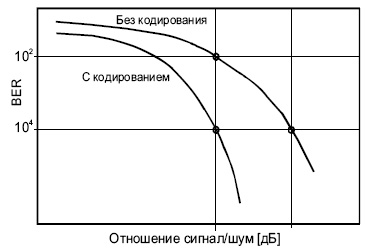
Рис.
4.8.
Турбо-кодек должен иметь столько же компонентных декодеров, сколько имеется кодировщиков на стороне передатчика. Декодеры соединяются последовательно.
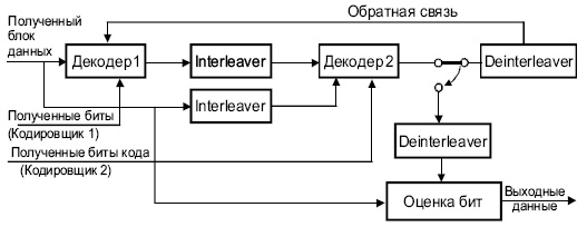
Рис.
4.9.
Турбо-декодер
Техника FEC находит все большее применение в телекоммуникациях, например, при передачи мультимедиа [2].
Следует помнить, что, как в случае FEC , так и в других известных методах коррекции ошибок ( BCH , Golay, Hamming и др.) скорректированный код является верным лишь с определенной конечной вероятностью.
Forward Error Correction (FEC) is a technique used to minimize errors in data transmission over communication channels. In real-time multimedia transmission, re-transmission of corrupted and lost packets is not useful because it creates an unacceptable delay in reproducing : one needs to wait until the lost or corrupted packet is resent. Thus, there must be some technique which could correct the error or reproduce the packet immediately and give the receiver the ability to correct errors without needing a reverse channel to request re-transmission of data. There are various FEC techniques designed for this purpose.
These are as follows :
1. Using Hamming Distance :
For error correction, the minimum hamming distance required to correct t errors is:
For example, if 20 errors are to be corrected then the minimum hamming distance has to be 2*20+1= 41 bits. This means, lots of redundant bits need to be sent with the data. This technique is very rarely used as we have large amount of data to be sent over the networks, and such a high redundancy cannot be afforded most of the time.
2. Using XOR :
The exclusive OR technique is quite useful as the data items can be recreated by this technique. The XOR property is used as follows –

If the XOR property is applied on N data items, we can recreate any of the data items P1 to PN by exclusive-Oring all of the items, replacing the one to be created by the result of the previous operation(R). In this technique, a packet is divided into N chunks, and then the exclusive OR of all the chunks is created and then, N+1 chunks are sent. If any chunk is lost or corrupted, it can be recreated at the receiver side.
Practically, if N=4, it means that 25 percent extra data has to be sent and the data can be corrected if only one out of the four chunks is lost.
3. Chunk Interleaving :
In this technique, each data packet is divided into chunks. The data is then created chunk by chunk(horizontally) but the chunks are combined into packets vertically. This is done because by doing so, each packet sent carries a chunk from several original packets. If the packet is lost, we miss only one chunk in each packet, which is normally acceptable in multimedia communication. Some small chunks are allowed to be missing at the receiver. One chunk can be afforded to be missing in each packet as all the chunks from the same packet cannot be allowed to miss.
Прямая коррекция ошибок (FEC)
Прямая коррекция ошибок (англ. Forward Error Correction, или сокр.: FEC) – мощный метод для улучшения производительности подверженных ошибкам каналов, используемый в системах связи. Производительность FEC может быть оценена на основе их расстояния от предела Шеннона.

VersaFEC®
VersaFEC – короткоблочная система с низкой задержкой на основе Low Density Parity Check (LDPC) кода, разработанная для поддержки чувствительных к скорости отклика приложений, таких, как сотовый обратный сигнал к спутнику, и обеспечения кодирования при минимальной сквозной задержке. VersaFEC обеспечивает превосходную альтернативу существующим LDPC и DVB-S2 система.
Технология VersaFEC разработана:
- Для обеспечения широкого выбора модуляции и кодовых комбинаций (ModCods). Эти новые комбинации обеспечивают кодирование, эквивалентное уже существующим LDPC и при этом значительно уменьшают задержку. Существующие LDPC коды (также как DVB-S2 коротко-блочные коды) используют блоки в 16 кбит, тогда как VersaFEC использует блоки в пределах от 2 кбит до 8.2 кбит.
- Для поддержки систем адаптивной модуляции и кодирования (ACM). ModCods были выбраны, для обеспечения непрерывной прогрессии с точки зрения графика функций Eb/No (отношение энергии сигнала, приходящейся на 1 бит принимаемого сообщения (Eb), к энергетической спектральной плотности шума (N0)) и спектральной эффективности, и сокращения задержек почти до теоретических минимумов.
Показатели кодирования VersaFEC
VersaFEC включает 12 настроек модуляции и кодирования (ModCods):
|
Модуляция |
Уровень кода |
Спектральная эффективность,bps/Hz |
Размер блока, bits |
Стандартное Eb/No,для BER = 5 x 10⁻⁸ |
Задержка в |
Min. Data Rate, CCM |
Max. Data Rate, CCM |
|
BPSK |
0.488 |
0.49 |
2k |
2.4 dB |
26 |
18 kbps |
5.7 Mbps |
|
QPSK |
0.533 |
1.07 |
4.1k |
2.2 dB |
53 |
20 kbps |
10 Mbps |
|
QPSK |
0.631 |
1.26 |
4.1k |
2.7 dB |
59 |
23 kbps |
10 Mbps |
|
QPSK |
0.706 |
1.41 |
4.1k |
3.4 dB |
62 |
26 kbps |
10 Mbps |
|
QPSK |
0.803 |
1.61 |
4.1k |
3.8 dB |
66 |
28 kbps |
12 Mbps |
|
8-QAM |
0.642 |
1.93 |
6.1k |
4.6 dB |
89 |
35 kbps |
12 Mbps |
|
8-QAM |
0.711 |
2.13 |
6.1k |
5.2 dB |
93 |
39 kbps |
12 Mbps |
|
8-QAM |
0.780 |
2.34 |
6.1k |
5.6 dB |
97 |
43 kbps |
12 Mbps |
|
16-QAM |
0.731 |
2.93 |
8.2k |
6.3 dB |
125 |
53 kbps |
12 Mbps |
|
16-QAM |
0.780 |
3.12 |
8.2k |
7.0 dB |
129 |
57 kbps |
14 Mbps |
|
16-QAM |
0.829 |
3.32 |
8.2k |
7.5 dB |
131 |
60 kbps |
14 Mbps |
|
16-QAM |
0.853 |
3.41 |
8.2k |
8.0 dB |
132 |
62 kbps |
16 Mbps |
Производительность кодов VersaFEC по отношению к пределу Шеннона показана на графике ниже. Для всех ModCods, VersaFEC находится в интервале от 0.7 до 1.0 дБ предела Шеннона. Производительность VersaFEC соответствует производительности DVB-S2 с блоками на 16 кбит.

По сравнению с Turbo Product кодами (TPC) VersaFEC обеспечивает более 1.0 дБ сокращения Eb/No. А как следствие приводит к увеличению пропускной способности и уменьшению размеров BUC/HPA.
Низкая степень задержки
VersaFEC специально предназначен для приложений c низкой задержкой. Для сравнения, уровень LDPC 2/3 8-QAM и Уровень VersaFEC 0.642 8-QAM обеспечивают практически идентичную спектральную эффективность и производительность Eb/No. Однако при 64 Кбит/с, задержка была уменьшена с 350 миллисекунд до 89 миллисекунд.

По сравнению с короткоблочным DVB-S2, VersaFEC обеспечивает значительное сокращение задержки в широком диапазоне. Например, у QPSK DVB-S2 уровня 2/3 и VersaFEC QPSK 0.631 имеют близкую по значению спектральную эффективность и производительность Eb/No. Однако при 64 Кбит/с, задержка VersaFEC составляет 59 мс, по сравнению с более 500 мс для DVB-S2.
В дополнение к тому, что используются блоки меньших размеров VersaFEC использует не чередующиеся систематические коды LDPC. В сравнении с чередующимися кодами DVB-S2, достигается значительного сокращения задержки. Общая сквозная задержка для высокого уровня кодирования систематическим кодом (таким как VersaFEC) асимптотически приближается к половине задержки чередованного кода (такого как DVB-S2).
VersaFEC® зарегистрированный товарный знак Comtech EF Data
VersaFEC-2
Обзор технологии VersaFEC-2
Comtech EF Data спроектировали и выпустили первое поколение систем VersaFEC весной 2007, которая использовалась в усовершенствованном спутниковом модеме CDM-625. Начальная форма сигнала была разработана для обеспечения высокой производительности и уменьшения скорости отклика операций постоянного кодирования и модуляции (CCM) и адаптивного кодирования и модуляции (ACM) на основе LDPC кодирования/декодирования для 5 Msps субканалов. Первое поколение VersaFEC очень быстро получило признание во многих отраслях и стало интегрироваться в решения с каналами передачи данных низкого и среднего уровней, которые требовали разложения сигнала в спектр с низкой задержкой. VersaFEC используется в настоящее время в трёх продуктах Comtech EF Data: модемы CDM-625 / CDM-625A / CDMER-625A, модемы CDM-570A / CDM-570AL и усовершенствованные VSAT платформы.
В то время как уровни производительности VersaFEC устанавливают высокую планку эффективности для каналов низких и средних уровней, рынок требует еще более высокой производительности и лучших результатов с точки зрения экономики. В связи с этим Comtech EF Data разрабатывает форму сигнала VersaFEC-2 и включает эту новую технологию в свой комплект продуктов, чтобы позволить мобильным сетевым операторам и поставщикам услуг продолжать контролировать затраты и постоянно увеличивать уровень обслуживания в соответствии с требованиями конечных пользователей. Цель этой статьи, описать следующее поколение разработки — системы расширенной формы сигнала VersaFEC-2 (VWS) и сравнить её со стандартами DVB-S2 и DVB-S2x вместе с её предшественником, VersaFEC, и выделить преимущества, замеченные при использовании новой технологии.
VersaFEC-2 (LDPC)
Высокоэффективная форма сигнала VersaFEC-2 была разработана для обеспечения оптимальных показателей производительности от 100 Ksps до 12.5 Msps в приложениях. Форма сигнала VersaFEC-2 состоит из 74 новых версий ModCod с новыми вариантами настроек модуляции и кодирования. VersaFEC-2, подобно промышленным стандартам DVB-S2 и DVB-S2x, обеспечивает два операционных режима, длинный блок и короткий блок. Длинноблочный режим предоставляет 38 вариантов ModCod с различными степенями кодирования и спектральной эффективности, большим, чем у DVB-S2 и равным DVB-S2x, а также степень задержки, составляющую до 1/8 от того же показателя, при использовании стандартов DVB-S2 и DVB-S2x. Короткоблочный режим VersaFEC-2 предоставляет 36 вариантов ModCod с лучшей производительностью, чем у зарекомендовавшей себя технологии VersaFEC с подобными или лучшими показателями задержки. Все совокупности высшего порядка в VersaFEC-2 являются цикличными для оптимальной производительности соотношения максимального к среднему значению и, как следствие, делает их менее подверженными падению производительности в нелинейных спутниковых каналах. Кроме того, новая 32-разрядная модуляция была введена для поддержки спектральной эффективности до 4.4 бит/с/Гц. Оба алгоритма CCM и ACM поддерживаются в обоих режимах Long-Block и Short-Block.
VersaFEC-2 (LDPC) vs. DVB-S2
Высокоэффективная форма сигнала VersaFEC-2 обеспечивает значительное преимущество производительности перед промышленным стандартом DVB-S2, а также перед его предшественником, VersaFEC. На рисунке 1 представлено сравнение длинно-блочного режима VersaFEC-2 и длинно-блочного DVB-S2.

Как изображено на рисунке 1, спектральная эффективность VersaFEC-2 выше, чем у стандарта DVB-S2 в наиболее распространенных сценариях (5 дБ-11 дБ сигнал/шум) приложений с низкими и средними скоростями передачи данных и на одном уровне со стандартом DVB-S2 при более высоких значениях показателя сигнал/шум. Увеличенные уровни производительности VersaFEC-2 непосредственно влияют на нижний график вследствие того, что:
- Дополнительная пропускная способность (Мбит/с) может быть задействована без расширения ширины канала.
- Минимальная ширина канала требуется для выбранного уровня пропускной способности (Мбит/с), что приводит к уменьшению потерь и снижению затрат ресурсов в операционной структуре для данной ширины потока.

Для мобильных операторов или поставщиков услуг связи, использование данной технологии даёт значительные преимущества. Для уже существующих сервисов — увеличение производительности в наиболее распространенных режимах работы непосредственно коррелирует увеличение прибыли, предполагая, что прайс-лист для конечного пользователя останется прежним. С другой стороны, измененная экономическая модель, следующая из уменьшения базовой стоимости, открывает новые рынки и области работы для мобильных операторов или поставщика услуг. Комбинация этих двух важных особенностей позволит предоставлять высококлассный уровень сервиса для конечных пользователей.
VersaFEC-2 vs. VersaFEC
На Рис. 2 представлено сравнение VersaFEC-2 с его предшественником, VersaFEC. Как показано на графике, Versa-FEC2 обеспечивает преимущество на 1.7 дБ больше в сравнении с VersaFEC.

Минимизация степени задержки
Ставка компании Comtech EF Data на то, что метод кодирования, который использует постоянное число символов в блоке, превзойдёт программный алгоритм, используемый в стандарте DVB, в котором за блочную единицу взят постоянный бит, была оправдана. Впоследствии, разработанный механизм был успешно интегрирован в VersaFEC, показав превосходные результаты относительно уровня задержки при передаче. Аналогично, VersaFEC-2, используя постоянный символ за блочную единицу, обладает значительными преимуществами в сравнении со стандартами DVB-S2 и DVB-S2x в минимизации степени задержки. Чтобы отметить это различие, в Табл. 1 продемонстрировано сравнение производительности VersaFEC-2 и DVB-S2 или DVB-S2x с точки зрения степени задержки канала на скорости 512 Кбит/с.
|
Форма сигнала |
ModCod |
Скорость передачи |
Задержка |
Преимущества VersaFEC-2 |
|
DVB-S2 or DVB-S2x |
QPSK Rate 0.5 Long Block |
512 Кб/с |
275 мс |
на 85% меньшая степень задержки, чем у DVB-S2 |
|
VersaFEC-2 |
QPSK Rate 0.489 Long Block |
512 Кб/с |
41 мс |
|
|
DVB-S2 or DVB-S2x |
QPSK Rate 0.5 Short Block |
512 Кб/с |
72 мс |
на 91% меньшая степень задержки, чем у DVB-S2 |
|
VersaFEC-2 |
QPSK Rate 0.489 Short Block |
512 Кб/с |
7 мс |
Таблица 1: таблица сравнения степени задержки VersaFEC-2 и DVB-S2/DVB-S2x
Как видно из Таблицы 1, вне зависимости от используемой вариации ModCod, показатель степени задержки VersaFEC-2 меньше чем при использовании стандарта DVB. Высокая степень задержки негативно влияет на показатели системы следующим образом:
- Снижение скорости установления соединения с интерактивными приложениями;
- Сильное сокращение скорости и качества работы приложений
- Возможность неработоспособности приложения.
Кодирующие устройства с технологией VersaFEC, были разработаны с нуля, в соответствии с требованиями базовых приложений. Для мобильных операторов чрезвычайно важно гарантировать, что базовые протоколы передачи для 2G, 3G и 4G сетей будут корректно и быстро функционировать. Допустимые значения степени задержки и джиттера этих протоколов очень низкие, и важно выбрать такое устройство передачи, которое позволило бы этим системам работать должным образом. Citrix и подобные бизнес-приложения чрезвычайно чувствительны к высокой степени задержки. Соединения, обладающие высоким уровень задержки, могут вызвать ненужные повторные передачи, деформацию сигнала в сети и, время от времени, сбои соединения.
Уменьшение времени восстановления полезного сигнала
Подобно преимуществам, обозначенным выше, использование алгоритма, где блочная единица — постоянное число символов, обеспечивает уменьшение времени восстановления полезного сигнала. В Табл. 2 продемонстрированы средние значения времени восстановления полезного сигнала в 1Msps для стандартов DVB-S2/DVB-S2x и VersaFEC-2.
|
Форма сигнала |
ModCod |
Размер блока |
Время восстановления полезного сигнала |
|
DVB-S2 or DVB-S2x |
QPSK Rate 0.5 Long Block |
1 Msps |
> 2 seconds |
|
VersaFEC-2 |
QPSK Rate 0.489 Long Block |
1 Msps |
< 60 msec |
|
DVB-S2 or DVB-S2x |
QPSK Rate 0.5 Short Block |
1 Msps |
> 2 seconds |
|
VersaFEC-2 |
QPSK Rate 0.489 Short Block |
1 Msps |
< 60 msec |
Таблица 2: типичное время восстановления полезного сигнала VersaFEC-2 по сравнению с DVB-S2/DVB-S2x
Время восстановления сигнала очень важно, когда каналы динамично расстраиваются и повторно настраиваются, как бывает при работе с динамическим операциями SCPC (dSCPC). С dSCPC операциями, время восстановления сигнала динамично изменяется для поддержки корректного распределения трафика в сети. Использования VersaFEC в новом проекте – гарант того, что время восстановления будет минимизировано и не ухудшит стабильность работы соединений, для которых существуют строгие требования к степени задержки и джиттеру.
Алгоритм адаптивного кодирования и модуляции (ACM)
Адаптивное Кодирование и Модуляция (ACM) являются методом передачи, в котором модуляция и прямая коррекция ошибок (FEC) происходят на лету, чтобы компенсировать ухудшение передачи на линии связи со спутником. В случае ухудшения связи, выбранная модуляция и кодирование “смещаются вниз”, чтобы позволить данным быть полученными на надлежащем уровне, чтобы гарантировать связь. Демодулятор ACM измеряет мощность полученного сигнала и использует эти данные, чтобы определить, произошло ли изменение в модуляции и гарантированно скорректировать ошибки. Когда в полученном сигнале регистрируются изменения C/N или Es/No, модуляция и кодирование изменяются снова, чтобы максимально удовлетворить требованиям к линии связи. Если уровень полезного сигнала увеличивается – модуляция и кодирование “возрастают” к более агрессивной (и более спектрально эффективный) комбинации. С другой стороны, если происходит дальнейшее ухудшение связи – модуляция и кодирование продолжают “уменьшаться” (вместе со спектральными полезными действиями), пока не достигнут уровня, гарантирующего стабильную связь.
Если технология ACM не используется, как это происходит с Постоянным Кодированием и Модуляцией (CCM), передаваемый блок данных должен быть сформирован для наихудших условий, чтобы гарантировать надлежащую связь. Другими словами, должны использоваться модуляция и кодирование, которые гарантировали бы работу при наиболее неблагоприятных условиях. Это огромный минус метода CCM, приводящий к большим затратам ресурсов.
Неблагоприятные условия окружающей среды, обусловленные природными явлениями, не являются постоянными, и подавляющее количество времени линия использует избыточная пропускная способность, которая в данный момент не является необходимой.
Те линии связи, которые используют ACM, получают следующие преимущества:

- Дополнительная пропускная способность (Мбит/с). Данные могут передаваться по каналу меньшей ширины в течение значительной части времени работы системы, так как ухудшения связи происходят нечасто.
- Уменьшение требуемой ширины канала. Для обеспечения законтрактованной пропускной способности (Мбит/с) требуется более узкий канал, поскольку работа в условиях плохого прохождения сигнала, и, соответственно, использование наименее «агрессивных» алгоритмов модуляции и кодирования будет происходить лишь в небольшие отрезки времени.
По сути, VersaFEC-2 разработан так, чтобы поддерживать различные алгоритмы демодуляции на принимающей стороне, исключив тем самым любые дополнительные издержки, которые могут возникнуть при реализации поддержки алгоритма ACM, являющегося ключевым в максимизации полезного действия линии связи.
Линейка продуктов, предлагаемых Comtech EF Data позволяет произвести многомерную оптимизацию, адаптированную к условиям потребителя. VersaFEC-2 – высокоэффективный метод модуляции и кодирования с низкой степенью задержки, преимущества которого дополнительно увеличиваются благодаря использованию алгоритма ACM. Основанный на большом опыте использования и преимуществах алгоритма VersaFEC, VersaFEC-2 добавляет много новых методов модуляции и кодирования, инновационных новых совокупностей и новых операционных режимов, которые позволяют ему лучше всего поддерживать сотовый сигнал и беспроводные каналы связи для IP-систем. Подобно своему предшественнику, алгоритм VersaFEC-2 может быть использован в обоих направлениях передачи и может быть объединен со сжатием DoubleTalk Carrier-in-Carrier, как например в усовершенствованном спутниковом модеме CDM-625A, чтобы достигнуть беспрецедентного спектрального полезного действия.
This is the approved revision of this page, as well as being the most recent.
In telecommunication, information theory, and coding theory, forward error correction (FEC) or channel coding is a technique used for controlling errors in data transmission over unreliable or noisy communication channels.
The central idea is the sender encodes the message in a redundant way by using an error-correcting code (ECC).
The American mathematician Richard Hamming pioneered this field in the 1940s and invented the first error-correcting code in 1950: the Hamming (7,4) code.
The redundancy allows the receiver to detect a limited number of errors that may occur anywhere in the message, and often to correct these errors without retransmission. FEC gives the receiver the ability to correct errors without needing a reverse channel to request retransmission of data, but at the cost of a fixed, higher forward channel bandwidth. FEC is therefore applied in situations where retransmissions are costly or impossible, such as one-way communication links and when transmitting to multiple receivers in multicast. FEC information is usually added to mass storage devices to enable recovery of corrupted data, is widely used in modems, and is used on systems where the primary memory is ECC memory.
FEC processing in a receiver may be applied to a digital bit stream or in the demodulation of a digitally modulated carrier. For the latter, FEC is an integral part of the initial analog-to-digital conversion in the receiver. The Viterbi decoder implements a soft-decision algorithm to demodulate digital data from an analog signal corrupted by noise. Many FEC coders can also generate a bit-error rate (BER) signal which can be used as feedback to fine-tune the analog receiving electronics.
The noisy-channel coding theorem establishes bounds on the theoretical maximum information transfer rate of a channel with some given noise level.
Some advanced FEC systems come very close to the theoretical maximum.
The maximum fractions of errors or of missing bits that can be corrected is determined by the design of the FEC code, so different forward error correcting codes are suitable for different conditions.
Contents
- 1 How it works
- 2 Averaging noise to reduce errors
- 3 Types of FEC
- 4 Concatenated FEC codes for improved performance
- 5 Low-density parity-check (LDPC)
- 6 Turbo codes
- 7 Local decoding and testing of codes
-
8 Interleaving
- 8.1 Example
- 8.2 Disadvantages of interleaving
- 9 Software for error-correcting codes
- 10 List of error-correcting codes
- 11 See also
- 12 Source
How it works[edit]
FEC is accomplished by adding redundancy to the transmitted information using an algorithm. A redundant bit may be a complex function of many original information bits. The original information may or may not appear literally in the encoded output; codes that include the unmodified input in the output are systematic, while those that do not are non-systematic.
A simplistic example of FEC is to transmit each data bit 3 times, which is known as a (3,1) repetition code. Through a noisy channel, a receiver might see 8 versions of the output, see table below.
| Triplet received | Interpreted as |
|---|---|
| 000 | 0 (error free) |
| 001 | 0 |
| 010 | 0 |
| 100 | 0 |
| 111 | 1 (error free) |
| 110 | 1 |
| 101 | 1 |
| 011 | 1 |
This allows an error in any one of the three samples to be corrected by «majority vote» or «democratic voting». The correcting ability of this FEC is:
- Up to 1 bit of triplet in error, or
- up to 2 bits of triplet omitted (cases not shown in table).
Though simple to implement and widely used, this triple modular redundancy is a relatively inefficient FEC. Better FEC codes typically examine the last several dozen, or even the last several hundred, previously received bits to determine how to decode the current small handful of bits (typically in groups of 2 to 8 bits).
Averaging noise to reduce errors[edit]
FEC could be said to work by «averaging noise»; since each data bit affects many transmitted symbols, the corruption of some symbols by noise usually allows the original user data to be extracted from the other, uncorrupted received symbols that also depend on the same user data.
- Because of this «risk-pooling» effect, digital communication systems that use FEC tend to work well above a certain minimum signal-to-noise ratio and not at all below it.
- This all-or-nothing tendency — the cliff effect — becomes more pronounced as stronger codes are used that more closely approach the theoretical Shannon limit.
- Interleaving FEC coded data can reduce the all or nothing properties of transmitted FEC codes when the channel errors tend to occur in bursts. However, this method has limits; it is best used on narrowband data.
Most telecommunication systems use a fixed channel code designed to tolerate the expected worst-case bit error rate, and then fail to work at all if the bit error rate is ever worse.
However, some systems adapt to the given channel error conditions: some instances of hybrid automatic repeat-request use a fixed FEC method as long as the FEC can handle the error rate, then switch to ARQ when the error rate gets too high;
adaptive modulation and coding uses a variety of FEC rates, adding more error-correction bits per packet when there are higher error rates in the channel, or taking them out when they are not needed.
Types of FEC[edit]
The two main categories of FEC codes are block codes and convolutional codes.
- Block codes work on fixed-size blocks (packets) of bits or symbols of predetermined size. Practical block codes can generally be hard-decoded in polynomial time to their block length.
- Convolutional codes work on bit or symbol streams of arbitrary length. They are most often soft decoded with the Viterbi algorithm, though other algorithms are sometimes used. Viterbi decoding allows asymptotically optimal decoding efficiency with increasing constraint length of the convolutional code, but at the expense of exponentially increasing complexity. A convolutional code that is terminated is also a ‘block code’ in that it encodes a block of input data, but the block size of a convolutional code is generally arbitrary, while block codes have a fixed size dictated by their algebraic characteristics. Types of termination for convolutional codes include «tail-biting» and «bit-flushing».
There are many types of block codes, but among the classical ones the most notable is Reed-Solomon coding because of its widespread use in compact discs, DVDs, and hard disk drives. Other examples of classical block codes include Golay, BCH, Multidimensional parity, and Hamming codes.
Hamming ECC is commonly used to correct NAND flash memory errors.
This provides single-bit error correction and 2-bit error detection.
Hamming codes are only suitable for more reliable single level cell (SLC) NAND.
Denser multi level cell (MLC) NAND requires stronger multi-bit correcting ECC such as BCH or Reed–Solomon.
NOR Flash typically does not use any error correction. which means that for every input and output signal a hard decision is made whether it corresponds to a one or a zero bit. In contrast, convolutional codes are typically decoded using soft-decision algorithms like the Viterbi, MAP or BCJR algorithms, which process (discretized) analog signals, and which allow for much higher error-correction performance than hard-decision decoding.
Nearly all classical block codes apply the algebraic properties of finite fields. Hence classical block codes are often referred to as algebraic codes.
In contrast to classical block codes that often specify an error-detecting or error-correcting ability, many modern block codes such as LDPC codes lack such guarantees. Instead, modern codes are evaluated in terms of their bit error rates.
Most forward error correction codes correct only bit-flips, but not bit-insertions or bit-deletions.
In this setting, the Hamming distance is the appropriate way to measure the bit error rate.
A few forward error correction codes are designed to correct bit-insertions and bit-deletions, such as Marker Codes and Watermark Codes.
The Levenshtein distance is a more appropriate way to measure the bit error rate when using such codes.
Concatenated FEC codes for improved performance[edit]
Classical (algebraic) block codes and convolutional codes are frequently combined in concatenated coding schemes in which a short constraint-length Viterbi-decoded convolutional code does most of the work and a block code (usually Reed-Solomon) with larger symbol size and block length «mops up» any errors made by the convolutional decoder. Single pass decoding with this family of error correction codes can yield very low error rates, but for long range transmission conditions (like deep space) iterative decoding is recommended.
Concatenated codes have been standard practice in satellite and deep space communications since Voyager 2 first used the technique in its 1986 encounter with Uranus. The Galileo craft used iterative concatenated codes to compensate for the very high error rate conditions caused by having a failed antenna.
Low-density parity-check (LDPC)[edit]
Low-density parity-check (LDPC) codes are a class of recently re-discovered highly efficient linear block
codes made from many single parity check (SPC) codes. They can provide performance very close to the channel capacity (the theoretical maximum) using an iterated soft-decision decoding approach, at linear time complexity in terms of their block length. Practical implementations rely heavily on decoding the constituent SPC codes in parallel.
LDPC codes were first introduced by Robert G. Gallager in his PhD thesis in 1960,
but due to the computational effort in implementing encoder and decoder and the introduction of Reed–Solomon codes,
they were mostly ignored until recently.
LDPC codes are now used in many recent high-speed communication standards, such as DVB-S2 (Digital video broadcasting), WiMAX (IEEE 802.16e standard for microwave communications), High-Speed Wireless LAN (IEEE 802.11n), 10GBase-T Ethernet (802.3an) and G.hn/G.9960 (ITU-T Standard for networking over power lines, phone lines and coaxial cable). Other LDPC codes are standardized for wireless communication standards within 3GPP MBMS (see fountain codes).
Turbo codes[edit]
Turbo coding is an iterated soft-decoding scheme that combines two or more relatively simple convolutional codes and an interleaver to produce a block code that can perform to within a fraction of a decibel of the Shannon limit. Predating LDPC codes in terms of practical application, they now provide similar performance.
One of the earliest commercial applications of turbo coding was the CDMA2000 1x (TIA IS-2000) digital cellular technology developed by Qualcomm and sold by Verizon Wireless, Sprint, and other carriers. It is also used for the evolution of CDMA2000 1x specifically for Internet access, 1xEV-DO (TIA IS-856). Like 1x, EV-DO was developed by Qualcomm, and is sold by Verizon Wireless, Sprint, and other carriers (Verizon’s marketing name for 1xEV-DO is Broadband Access, Sprint’s consumer and business marketing names for 1xEV-DO are Power Vision and Mobile Broadband, respectively).
Local decoding and testing of codes[edit]
Sometimes it is only necessary to decode single bits of the message, or to check whether a given signal is a codeword, and do so without looking at the entire signal. This can make sense in a streaming setting, where codewords are too large to be classically decoded fast enough and where only a few bits of the message are of interest for now. Also such codes have become an important tool in computational complexity theory, e.g., for the design of probabilistically checkable proofs.
Locally decodable codes are error-correcting codes for which single bits of the message can be probabilistically recovered by only looking at a small (say constant) number of positions of a codeword, even after the codeword has been corrupted at some constant fraction of positions. Locally testable codes are error-correcting codes for which it can be checked probabilistically whether a signal is close to a codeword by only looking at a small number of positions of the signal.
Interleaving[edit]
Interleaving is frequently used in digital communication and storage systems to improve the performance of forward error correcting codes. Many communication channels are not memoryless: errors typically occur in bursts rather than independently. If the number of errors within a code word exceeds the error-correcting code’s capability, it fails to recover the original code word. Interleaving ameliorates this problem by shuffling source symbols across several code words, thereby creating a more uniform distribution of errors. Therefore, interleaving is widely used for burst error-correction.
The analysis of modern iterated codes, like turbo codes and LDPC codes, typically assumes an independent distribution of errors. Systems using LDPC codes therefore typically employ additional interleaving across the symbols within a code word.
For turbo codes, an interleaver is an integral component and its proper design is crucial for good performance. The iterative decoding algorithm works best when there are not short cycles in the factor graph that represents the decoder; the interleaver is chosen to avoid short cycles.
Interleaver designs include:
- rectangular (or uniform) interleavers (similar to the method using skip factors described above)
- convolutional interleavers
- random interleavers (where the interleaver is a known random permutation)
- S-random interleaver (where the interleaver is a known random permutation with the constraint that no input symbols within distance S appear within a distance of S in the output).
- Another possible construction is a contention-free quadratic permutation polynomial (QPP). It is used for example in the 3GPP Long Term Evolution mobile telecommunication standard.
In multi-carrier communication systems, interleaving across carriers may be employed to provide frequency diversity, e.g., to mitigate frequency-selective fading or narrowband interference.
Example[edit]
Transmission without interleaving:
Error-free message: aaaabbbbccccddddeeeeffffgggg
Transmission with a burst error: aaaabbbbccc____deeeeffffgggg
Here, each group of the same letter represents a 4-bit one-bit error-correcting codeword. The codeword cccc is altered in one bit and can be corrected, but the codeword dddd is altered in three bits, so either it cannot be decoded at all or it might be decoded incorrectly.
With interleaving:
Error-free code words: aaaabbbbccccddddeeeeffffgggg
Interleaved: abcdefgabcdefgabcdefgabcdefg
Transmission with a burst error: abcdefgabcd____bcdefgabcdefg
Received code words after deinterleaving: aa_abbbbccccdddde_eef_ffg_gg
In each of the codewords aaaa, eeee, ffff, gggg, only one bit is altered, so one-bit error-correcting code will decode everything correctly.
Transmission without interleaving:
Original transmitted sentence: ThisIsAnExampleOfInterleaving
Received sentence with a burst error: ThisIs______pleOfInterleaving
The term «AnExample» ends up mostly unintelligible and difficult to correct.
With interleaving:
Transmitted sentence: ThisIsAnExampleOfInterleaving...
Error-free transmission: TIEpfeaghsxlIrv.iAaenli.snmOten.
Received sentence with a burst error: TIEpfe______Irv.iAaenli.snmOten.
Received sentence after deinterleaving: T_isI_AnE_amp_eOfInterle_vin_...
No word is completely lost and the missing letters can be recovered with minimal guesswork.
Disadvantages of interleaving[edit]
Use of interleaving techniques increases total delay. This is because the entire interleaved block must be received before the packets can be decoded. Also interleavers hide the structure of errors; without an interleaver, more advanced decoding algorithms can take advantage of the error structure and achieve more reliable communication than a simpler decoder combined with an interleaver.
Software for error-correcting codes[edit]
Simulating the behaviour of error-correcting codes (ECCs) in software is a common practice to design, validate and improve ECCs. The upcoming wireless 5G standard raises a new range of applications for the software ECCs: the Cloud Radio Access Networks (C-RAN) in a Software-defined radio (SDR) context. The idea is to directly use software ECCs in the communications. For instance in the 5G, the software ECCs could be located in the cloud and the antennas connected to this computing resources: improving this way the flexibility of the communication network and eventually increasing the energy efficiency of the system.
In this context, there are various available Open-source software listed below (non exhaustive).
- AFF3CT(A Fast Forward Error Correction Tool): a full communication chain in C++ (many supported codes like Turbo, LDPC, Polar codes, etc.), very fast and specialized on channel coding (can be used as a program for simulations or as a library for the SDR).
- IT++: a C++ library of classes and functions for linear algebra, numerical optimization, signal processing, communications, and statistics.
- OpenAir: implementation (in C) of the 3GPP specifications concerning the Evolved Packet Core Networks.
List of error-correcting codes[edit]
| Distance | Code |
|---|---|
| 2 (single-error detecting) | Parity |
| 3 (single-error correcting) | Triple modular redundancy |
| 3 (single-error correcting) | perfect Hamming such as Hamming(7,4) |
| 4 (SECDED) | Extended Hamming |
| 5 (double-error correcting) | |
| 6 (double-error correct-/triple error detect) | |
| 7 (three-error correcting) | perfect binary Golay code |
| 8 (TECFED) | extended binary Golay code |
<!—it would be nice to have some categorization of codes, e.g. into linear codes, cyclic codes, etc.—>
- AN codes
- BCH code, which can be designed to correct any arbitrary number of errors per code block.
- Berger code
- Constant-weight code
- Convolutional code
- Expander codes
- Group codes
- Golay codes, of which the Binary Golay code is of practical interest
- Goppa code, used in the McEliece cryptosystem
- Hadamard code
- Hagelbarger code
- Hamming code
- Latin square based code for non-white noise (prevalent for example in broadband over powerlines)
- Lexicographic code
- Long code
- Low-density parity-check code, also known as Gallager code, as the archetype for sparse graph codes
- LT code, which is a near-optimal rateless erasure correcting code (Fountain code)
- m of n codes
- Online code, a near-optimal rateless erasure correcting code
- Polar code (coding theory)
- Raptor code, a near-optimal rateless erasure correcting code
- Reed–Solomon error correction
- Reed–Muller code
- Repeat-accumulate code
- Repetition codes, such as Triple modular redundancy
- Spinal code, a rateless, nonlinear code based on pseudo-random hash functions
- Tornado code, a near-optimal erasure correcting code, and the precursor to Fountain codes
- Turbo code
- Walsh–Hadamard code
- Cyclic redundancy checks (CRCs) can correct 1-bit errors for messages at most <math>2^{n-1}-1</math> bits long for optimal generator polynomials of degree <math>n</math>, see Mathematics of cyclic redundancy checks#Bitfilters
See Also on BitcoinWiki[edit]
- Code rate
- Erasure codes
- Soft-decision decoder
- Error detection and correction
- Error-correcting codes with feedback
- Burst error-correcting code
Source[edit]
http://wikipedia.org/
Введение
Одной из ключевых задач, решаемых разработчиками любых систем связи (и в первую очередь систем радиосвязи) является задача обнаружения и исправления ошибок, количество которых в сотовых сетях определяется двумя факторами – внешними помехами, а также интерференцией, возникающей от передатчиков соседних базовых станций. Последний фактор является особенно важным для одночастотных систем мобильной связи, включая 4G—LTE и 5G.
Рассмотрим основные технологии и понятия, связанные с решением обозначенной задачи на сетях 4G-LTE и 5G:
Схема с прямой коррекцией ошибок – FEC (Forward Error Correction)
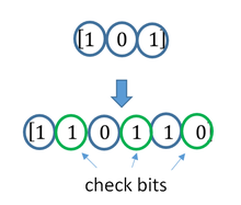
Суть схемы FEC заключается в преобразовании передатчиком передаваемых блоков данных в кодовые слова (путем канального кодирования и внесения избыточной информации) таким образом, чтобы предоставить приемнику возможность обнаруживать и восстанавливать определенное количество битов, искаженных при передаче – см. Рис. 1. Подобные системы характеризуются скоростью кодирования, представляющей собой отношение длины полезного блока данных к длине кодового слова. Недостатком является потеря функциональности при превышении кол-ва ошибок исправляющей способности кода.

Рис. 1 (FEC + Rate matching)
Выравнивание скорости – Rate matching
Выравнивание скорости представляет собой функциональный модуль, дополняющий технологию прямой коррекции ошибок. Данный модуль удаляет (или «выкалывает») часть битов из кодовых слов, формируемых схемой FEC, уменьшая их длину до требуемого размера транспортного блока. Тем самым, с одной стороны снижается объем данных, который передается по каналу связи, с другой – сохраняется достаточная исправляющая способность системы. На приемной стороне в выколотые передатчиком позиции вставляются фиктивные биты, после чего кодовые слова восстановленной длины направляются на канальный декодер.
Схема с автоматическим запросом повторной передачи – ARQ (Automatic Repeat request)
Суть схемы ARQ заключается в вычислении передатчиком циклического избыточного кода (CRC – Cyclic Redundancy Check) передаваемого блока данных, что позволяет приемнику путем сравнения вычисленного и принятого значений CRC обнаруживать пакеты, содержащие искаженные данные и запрашивать их повторную передачу – см. Рис. 2.
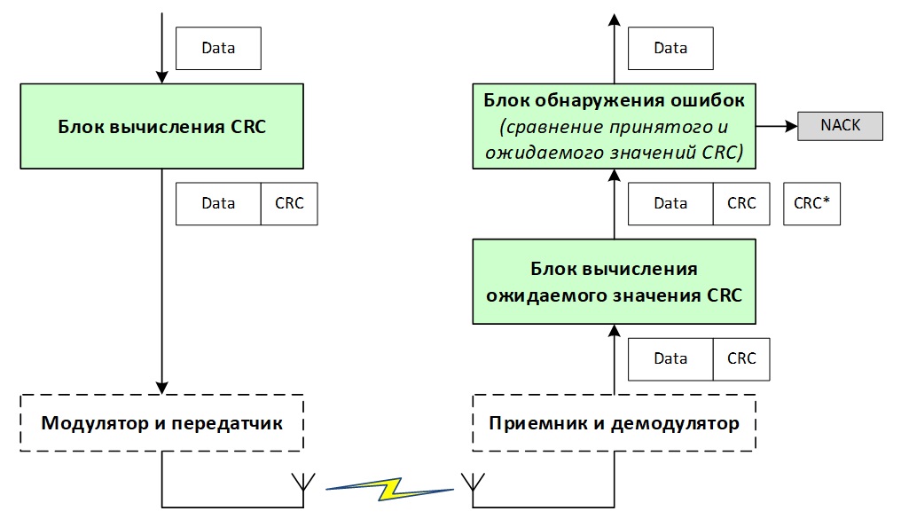
Рис. 2 (ARQ)
Обычно схема ARQ использует метод, называемый выборочной ретрансляцией (Рис. 3), в котором приемник ожидает получение нескольких блоков данных до их подтверждения. Этот метод с одной стороны позволяет передатчику продолжать отправлять пакеты, не дожидаясь их подтверждения, а с другой стороны вносит существенную задержку в случае необходимости повторной передачи. Следовательно, схема ARQ подходит только для потоков данных нереального времени, таких как веб-страницы и электронные письма. Кроме уже упомянутой задержки, недостатком схемы ARQ является дополнительная нагрузка на канал связи, поскольку даже единичная ошибка требует повторной передачи всего пакета данных.

Рис. 3 (метод выборочной ретрансляции ARQ)
Гибридная схема с автоматическим запросом повторной передачи – HARQ (Hybrid ARQ)
Hybrid ARQ комбинирует вышеописанные схемы, применяемые для коррекции ошибок (FEC, ARQ – см. Рис. 4). В соответствии с этим, передающая сторона:
- осуществляет кодирование передаваемых данных FEC кодом (с применением функции выравнивания скорости), что позволяет приемнику восстанавливать искаженные при передаче биты (в пределах исправляющей способности кода);
- вычисляет код CRC и добавляет его к передаваемым данным, давая возможность приемнику детектировать блоки, содержащие неисправленные посредством FEC ошибки, и запрашивать их повторную передачу.

Рис. 4 (HARQ)
Схемы HARQ могут быть синхронными и асинхронными. В синхронном режиме повторная передача блоков данных осуществляется в строго определенные интервалы времени. При этом не требуется передача номера HARQ процесса (см. п.3) и номера Redundancy version (RV – см. п.2), что снижает долю сигнального трафика. Так, каждый субфрейм (sub frame) планировщик базовой станции выделяет ресурс для передачи только одному предопределенному HARQ процессу с предопределенным RV, и в системе, содержащей 8 процессов, каждый процесс осуществляет передачу строго раз в 8мс.
В асинхронном режиме передача данных HARQ процессами может осуществляться в любое время, что дает возможность планировщику базовой станции более гибко распределять ресурсы сети. Плата за эту гибкость – увеличение накладных расходов на передачу сигнальной информации (номер HARQ процесса, а также номер RV включаются в блок управляющей информации – DCI, передаваемый по каналу PDCCH).
На восходящих линиях (Uplink) сетей 4G—LTE и 5G используется синхронный режим HARQ, на нисходящей (Downlink) – асинхронный.
Также алгоритмы HARQ могут функционировать в адаптивном и неадаптивном режимах. В адаптивном режиме при повторной передаче пакетов допускается изменение таких параметров как скорость кодирования, номера и кол-во выделенных ресурсных блоков, схема модуляции. По аналогии с асинхронной передачей адаптивный режим повышает гибкость распределения ресурсов сети, предоставляет механизмы для увеличения надежности приема данных (например, за счет понижения индекса модуляции), но при этом увеличивает долю сигнального трафика на канале PDCCH.
Неадаптивный режим не предполагает изменения параметров при повторной передаче пакетов.
Упреждающая коррекция ошибок FEC (Forward Error Correction) нашла широкое применение в технике оптической связи последнего поколения. Её использование предусмотрено стандартами передачи SDH, OTH, Ethernet.
Для обнаружения и исправления ошибок чаще всего используются циклические блочные коды (коды Хэмминга, коды Боуза-Чоудхури-Хоквенгема (БХЧ), коды Рида-Соломона (RS). Подробные сведения о этих кодах приведены в ряде изданий [115, 116,117].
В технике оптических систем нашли широкое применение коды Рида-Соломона (Reed-Solomon – RS). При использовании этих кодов данные обрабатываются порциями по m-бит, которые именуют символами. Код RS(n, k) характеризуется следующими параметрами:
- длина символа m бит;
- длина блока n = (2m – 1) символов = m(2m – 1) бит;
- длина блока данных k символов;
- n – k = 2t символов = m(2t) бит;
- минимальное расстояние Хэмминга dmin = (2t + 1);
- число ошибок, требующих исправления t.
Алгоритм кодирования RS(n, k) расширяет блок k символов до размера n, добавляя (n – k) избыточных контрольных символов. Как правило, длина символа является степенью 2 и широко используется значение m = 8, т.е. символ равен одному байту. Для исправления всех 1 и 3 битовых ошибок в символах требуется выполнение неравенства:
![]() . (8.22)
. (8.22)
Рисунок 8.33. Образование строки с блоком контроля FEC
Для исправления ошибок применяется 16-символьный код RS(255, 239), который относится к классу линейных циклических блочных кодов.Каждый цикл передачи, например, STM-N или OTUk разбивается на блоки символов данных по 239 байт. Каждому такому блоку вычисляется контрольный блок из 16 символов – байт и присоединяется к 239 байтам, 240-255 байты. Т.о. n = 255, k = 239, т.е. RS(255, 239). Объединенный блок k и n – k образуют подстроку цикла. Синхронное побайтовое мультиплексирование подстрок образует одну строку цикла (рисунок 8.33).Порядок передачи строки слева направо. При формировании блока (n – k) блок данных k сдвигается на n – k и делится на производящий полином:
Р = х8 + х4 + х3 + х2 + 1. (8.23)
В результате получается частное от деления и остаток деления длиной n – k. Блок данных k и остаток деления объединяются, образуя подстроку. После передачи подстроки на приемной стороне производится ее деление на производящий полином Р, аналогичный тому что был на передаче. если после деления остаток ноль, то передача прошла без ошибок. Если после деления остаток не равен нулю, то это признак ошибки. Место положения ошибки в блоке k обнаруживается по остатку, например табличным методом.
Исправлению подлежит заданное количество ошибок в символе (1, 2 или более в байте). Благодаря тому, что RS(255, 239) имеет расстояние Хэмминга dmin = 17 можно корректировать до 8 символьных ошибок.
Таблица 8.6 Пример результата расчета коэффициента ошибок на выходе декодера FEC RS(255, 239)
При этом число обнаруживаемых ошибок составляет 16 в подстроке с FEC. В таблице 8.6 приведен пример теоретически рассчитанного коэффициента ошибок на выходе декодера FEC RS(255, 239) [117].Практическая эффективность кодирования RS(255, 239) может составить от 5 до 8 дБ, т.е. FEC позволяет увеличивать длины участков передачи по сравнению с системами без FEC. Это особенно актуально на протяженных линиях оптической передачи и при реконструкции, когда производится переход на высокие скоростные режимы, например, с 2.5Гбит/с на 10Гбит/с. При этом очень важно сохранить длины участков передачи существующей сети и не строить дополнительных промежуточных станций.
Пример оценки эффективности применения упреждающей коррекции при цифровой передаче приведен на рисунке 8.34.
Рисунок 8.34. Эффективность использования FEC