- Manuals
- Brands
- Genie Manuals
- Lifting Systems
- GS-4047
Manuals and User Guides for Genie GS-4047. We have 7 Genie GS-4047 manuals available for free PDF download: Service And Repair Manual, Maintenance Manual, Operator’s Manual

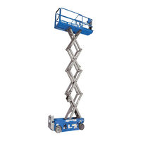
Genie GS-4047 Service And Repair Manual (343 pages)
Scissor Lifts
Brand: Genie
|
Category: Lifting Systems
|
Size: 19.04 MB
Table of Contents
-
Introduction
2
-
Find a Manual for this Model
2
-
Serial Number Range
3
-
Revision History
4
-
Serial Number Legend
6
-
-
Safety Rules
7
-
Table of Contents
9
-
April
12
-
Gs-1530 / Gs
14
-
-
Specifications
17
-
Machine Specifications
17
-
Gs-30 • Gs-32 • Gs-46 • Gs
17
-
April
18
-
-
Performance Specifications (Models Without Proportional Lift Function)
19
-
April
19
-
Gs-30 • Gs-32 • Gs-46 • Gs
20
-
-
Performance Specifications (Models with Proportional Lift)
21
-
Hydraulic Oil Specifications
23
-
Hydraulic Component Specifications
26
-
Manifold Component Specifications
27
-
Hydraulic Hose and Fitting Torque Specifications
28
-
Torque Procedure
29
-
-
Repair Procedures
31
-
Introduction
31
-
-
Platform Controls
33
-
Circuit Board
35
-
Joystick
36
-
Platfrom Controls Alarm
36
-
Platform Emergency Stop Button
37
-
-
Ground Controls
38
-
Software Revision Level
39
-
Machine Setup
40
-
Loading or Updating Machine Software
41
-
Using a Wi-Fi Router to Connect to the Smartlink Web Service Tool
46
-
Service Override Mode
48
-
Level Sensors
50
-
Manual Platform Lowering Cable
65
-
Outrigger Calibration
67
-
-
Hydraulic Tank
68
-
Hydraulic Pump
69
-
How to Remove the Hydraulic Pump
70
-
-
Manifolds
72
-
Function Manifold Components — GS-1530, GS-1532, GS-1930 and GS-1932
72
-
Function Manifold Components — GS-2032, GS-2632, GS-3232, GS-2046, GS-2646 and GS-3246
74
-
Function Manifold Components — GS-4047
76
-
Check Valve Manifold Components — GS-1530, GS-1532, GS-1930 and GS-1932
78
-
Lift Pressure Selector Manifold Components — GS-4047
79
-
Outrigger Function Manifold Components — GS-3232
80
-
Outrigger Cylinder Manifold Components — GS-3232
81
-
Valve Adjustments — Function Manifold
82
-
Valve Coils
88
-
-
Steer Axle Components
90
-
Yoke and Drive Motor
90
-
Steer Cylinder
91
-
Steer Bellcrank
92
-
-
Non-Steer Axle Components
93
-
Drive Brake
93
-
-
Brake Release Hand Pump Components
94
-
Scissor Components
95
-
Scissor Assembly, GS-1530 and GS-1532
96
-
Scissor Assembly, GS-1930 and GS-1932
102
-
Scissor Assembly, GS-2032 and GS-2046
110
-
Scissor Assembly, GS-2632 and GS-2646
117
-
Scissor Assembly, GS-3232 and GS-3246
125
-
Scissor Assembly, GS-4047
134
-
Scissor Arm Wear Pads
142
-
Platform Height Sensor
144
-
Lift Cylinder
146
-
Pressure Transducer
157
-
Platform Overload System
159
-
Platform Overload Recovery
164
-
-
Platform Components
166
-
Platform
166
-
Platform Extension Deck
167
-
-
Battery Charger
168
-
Selecting a Charge Profile
169
-
-
Diagnostics
171
-
Introduction
171
-
GCON I/O Map Without Load Sense (All Machines Except GS-3232)
174
-
GCON I/O Map with Load Sense (All Machines Except GS-3232)
175
-
GCON I/O Map Without Load Sense GS-3232 Only)
176
-
GCON I/O Map with Load Sense (GS-3232 Only)
178
-
Operation Indicator Codes (OIC)
180
-
Diagnostic Trouble Codes (DTC)
180
-
Troubleshooting «HXXX» and «PXXX» Faults
181
-
Fault Inspection Procedure
182
-
Type «HXXX» Faults
184
-
Type «PXXX» Faults
188
-
Type «UXXX» Faults
189
-
Type «FXXX» Faults
192
-
Type «CXXX» Faults
195
-
Battery Charger
197
-
Charger Fault Codes
198
-
Charger Error Codes
199
-
-
-
Schematics
203
-
Introduction
203
-
Electrical Component and Wire Color Legends
204
-
Wiring Diagram Ground and Platform Controls
206
-
Limit Switch Legend
207
-
Electrical Symbol Legend
208
-
Hydraulic Symbols Legend
209
-
-
Hydraulic Schematics
210
-
Hydraulic Component Reference Legend
210
-
Hydraulic Component Abbreviation Legend
211
-
Hydraulic Schematic, GS-1530, 1532, 1930, 1932 (from Serial Number GS3010A-110000, GS3011C-10000, GS3014D-101, GS3016P-142281)
212
-
GS3212C-10000 to GS3214C-11873, GS4612A-110000 to
213
-
-
Hydraulic Schematic, GS-2032, 2632, 3232, 2046, 2646, 3246
214
-
Hydraulic Schematic, GS-2032, 2632, 3232, 2046, 2646, 3246 (from Serial Number GS3214A-119071, GS3214C-11874
214
-
Hydraulic Schematic, GS-3232 (from Serial Number GS3211A-110000, GS3212C-10000, GS3216P-142677)
215
-
Hydraulic Schematic, GS-4047 (from Serial Number GS4712C-101 to GS4714C-1459)
216
-
Hydraulic Schematic, GS-4047
216
-
(From Serial Number GS4714C-1460, GS4714D-101, GS4716P-101)
217
-
(From Serial Number GS3010A-110000 to GS3011A-110827)
220
-
-
-
Electrical Schematics — ANSI / CSA Models
220
-
Electrical Schematic, GS-1530 / GS-1930, ANSI / CSA (from Serial Number GS3011A-110828 to GS3014A-136972, GS3014D-101 to GS3015D-1113)
224
-
Electrical Schematic, GS-1530 / GS-1930
224
-
GS3016P-142281 to GS3016P-158208)
228
-
-
Electrical Schematic, GS-1530/1930, ANSI/CSA
231
-
Electrical Schematic, GS-3232, ANSI / CSA
233
-
(From Serial Number GS3211A-110000 to GS3214A-135714)
234
-
-
Electrical Schematic, GS-3232, ANSI / CSA
234
-
(From Serial Number GS3214A-135715 to GS3215A-141898)
238
-
-
Electrical Schematic, GS-3232, ANSI / CSA (from Serial Number GS3215A-141899, GS3216P-142677 to GS3216P-146462)
242
-
Electrical Schematic, GS-2032, 2632, 2046, 2646, ANSI / CSA
249
-
GS4612A-110000 to GS4614A-135366, GS4613D-101 to GS4615D-1303)
250
-
-
Electrical Schematic, GS-2032, 2632, 2046, 2646, ANSI/CSA
250
-
GS4614A-135367 to GS4615A-137959, GS4615D-1304)
254
-
-
Electrical Schematic, GS-2032, 2632, 2046, 2646, ANSI / CSA (from Serial Number GS3216P-146463, GS4616D-4433, GS4616P-139711)
262
-
Electrical Schematic, GS-3246, GS4047 ANSI / CSA (from Serial Numbers GS4616D-4433, GS4616P-139711, GS4716D-3102, GS4716P-101)
272
-
-
Electrical Schematics — CE and Australia Models
273
-
Electrical Schematic GS-1530, 1532, 1930, 1932, (from Serial Number GS3010A-110000 to GS3011A-110827) as / CE
274
-
Electrical Schematic, GS-1530/32_GS-1930/32 (from Serial Number GS3011A-110828 to GS3014A-136972, GS3011C-10000 to
278
-
Electrical Schematic, GS-1530, 1532, 1930, 1932, AS/CE
282
-
GS3015D-1114 to GS3016D-5426, GS3016P-142281 to GS3016P-158208)
282
-
-
Electrical Schematic, GS-1530, 1532, 1930, 1932, AS/CE
286
-
(From Serial Numbers GS3015D-5427, GS3016P-158209)
286
-
-
Electrical Schematic, GS-3232, as / CE
288
-
Gs3215C-14503)
288
-
-
Electrical Schematic, GS-3232, as / CE (from Serial Number GS3214A-135715 to GS3215A-141898, GS3215C-14504)
292
-
Electrical Schematic, GS-3232, as / CE (from Serial Numbers GS3215A-141899, GS3216P-142676 to GS3216P-146462)
296
-
Electrical Schematic, GS-3232, CE / as (from Serial Number GS3216P-146463)
300
-
Electrical Schematic, GS-2032, 2632, 2046, 2646, as / CE
303
-
GS4613D-101 to GS4615D-1303)
304
-
-
Electrical Schematic, GS-2032, 2632, 2046, 2646, AS/CE
308
-
GS3215C-14378, GS4614A-135367 to GS4615A-137959, GS4615C-14504, GS4615D-1304)
308
-
-
Electrical Schematic, GS-2032, 2632, 2046, 2646, as / CE
312
-
GS3216P-146462, GS4615A-137960, GS4616P-138362 to
312
-
-
Electrical Schematic, GS-2032, 2632, 2046, 2646, as / CE (from Serial Numbers GS3216P-146463, GS4616P-139711)
316
-
Electrical Schematic, GS-3246, as / CE
318
-
Electrical Schematic, GS-3246, as / CE
322
-
Electrical Schematic, GS-3246, as / CE
326
-
GS4615A-137960, GS4616P-138362 GS4616P to GS4616P-139710)
326
-
-
Electrical Schematic, GS-3246, as / CE (from Serial Number GS4616D-4433, GS4616P-139711)
330
-
Electrical Schematic, GS-4047, as / CE
332
-
GS4712C-101 to GS4715C-2130, GS4714D-101 to GS4715D-749)
332
-
-
Electrical Schematic, GS-4047, as / CE (from Serial Number GS4715C-2131, GS4715D-750 to GS4716D-3101)
336
-
Electrical Schematic, GS-4047, as / CE (from Serial Number GS4716D-3102)
340
-
-
Electrical Schematic — Foot Switch (Option) All Models
341
-
Foot Switch (Option) All Models
342
-
Advertisement
Genie GS-4047 Service And Repair Manual (335 pages)
Scissor lifts
Brand: Genie
|
Category: Boom Lifts
|
Size: 17.47 MB
Table of Contents
-
Find a Manual for this Model
2
-
Serial Number Range
3
-
Revision History
4
-
Serial Number Legend
5
-
Safety Rules
6
-
Table of Contents
8
-
-
Specifications
17
-
Machine Specifications
17
-
Performance Specifications (Models Without Proportional Lift Function)
19
-
Performance Specifications (Models with Proportional Lift)
21
-
Hydraulic Specification
23
-
Hydraulic Component Specifications
26
-
Manifold Component Specifications
27
-
Hydraulic Hose and Fitting Torque Specifications
28
-
Torque Procedure
29
-
-
Repair Procedures
31
-
Introduction
31
-
-
Platform Controls
33
-
Circuit Board
35
-
Joystick
36
-
Platfrom Controls Alarm
36
-
Platform Emergency Stop Button
37
-
-
Ground Controls
38
-
Software Revision Level
39
-
Machine Setup
40
-
Loading or Updating Machine Software
41
-
Using a Wi-Fi Router to Connect to the Smartlink Web Service Tool
46
-
Service Override Mode
48
-
Level Sensors
50
-
Manual Platform Lowering Cable
65
-
Outrigger Calibration
67
-
-
Hydraulic Tank
68
-
Hydraulic Pump
69
-
Function Pump
69
-
How to Remove the Hydraulic Pump
70
-
-
Manifolds
72
-
Function Manifold Components — GS-1530, GS-1532, GS-1930 and GS-1932
72
-
Function Manifold Components — GS-2032, GS-2632, GS-3232, GS-2046, GS-2646 and GS-3246
74
-
Function Manifold Components — GS-4047
76
-
Check Valve Manifold Components — GS-1530, GS-1532, GS-1930 and GS-1932
78
-
Lift Pressure Selector Manifold Components — GS-4047
79
-
Outrigger Function Manifold Components — GS-3232
80
-
Outrigger Cylinder Manifold Components — GS-3232
81
-
Valve Adjustments — Function Manifold
82
-
Valve Coils
88
-
-
Steer Axle Components
90
-
Yoke and Drive Motor
90
-
Steer Cylinder
91
-
Steer Bellcrank
92
-
-
Non-Steer Axle Components
93
-
Drive Brake
93
-
-
Brake Release Hand Pump Components
94
-
Scissor Components
95
-
Scissor Assembly, GS-1530 and GS-1532
96
-
Scissor Assembly, GS-1930 and GS-1932
102
-
Scissor Assembly, GS-2032 and GS-2046
110
-
Scissor Assembly, GS-2632 and GS-2646
117
-
Scissor Assembly, GS-3232 and GS-3246
125
-
Scissor Assembly, GS-4047
134
-
Scissor Arm Wear Pads
142
-
Platform Height Sensor
144
-
Lift Cylinder
146
-
Pressure Transducer
157
-
Platform Overload System
159
-
Platform Overload Recovery
164
-
-
Platform Components
166
-
Platform
166
-
Platform Extension Deck
167
-
-
Diagnostics
169
-
Introduction
169
-
GCON I/O Map Without Load Sense (All Machines Except GS-3232)
172
-
GCON I/O Map with Load Sense (All Machines Except GS-3232)
173
-
GCON I/O Map Without Load Sense GS-3232 Only)
174
-
GCON I/O Map with Load Sense (GS-3232 Only)
176
-
Operation Indicator Codes (OIC)
178
-
Diagnostic Trouble Codes (DTC)
178
-
Troubleshooting «HXXX» and «PXXX» Faults
179
-
Fault Inspection Procedure
180
-
Type «HXXX» Faults
182
-
Type «PXXX» Faults
186
-
Type «UXXX» Faults
187
-
Type «FXXX» Faults
190
-
Type «CXXX» Faults
193
-
-
Schematics
195
-
Introduction
195
-
Electrical Component and Wire Color Legends
196
-
Wiring Diagram Ground and Platform Controls
198
-
Limit Switch Legend
199
-
Electrical Symbol Legend
200
-
Hydraulic Symbols Legend
201
-
-
Hydraulic Schematics
202
-
Hydraulic Component Reference Legend
202
-
Hydraulic Component Abbreviation Legend
203
-
Hydraulic Schematic, GS-1530, 1532, 1930, 1932 (from Serial Number GS3010A-110000, GS3011C-10000, GS3014D-101, GS3016P-142281)
204
-
GS4614C-10000 to GS4614C-12073)
205
-
-
Hydraulic Schematic, GS-2032, 2632, 3232, 2046, 2646, 3246
206
-
Gs4614C-12074, Gs4614D-101)
206
-
-
Hydraulic Schematic, GS-3232 (from Serial Number GS3211A-110000) (from Serial Number GS3212C-10000)
207
-
Hydraulic Schematic, GS-4047 (from Serial Number GS4712C-101 to GS4714C-1459)
208
-
Hydraulic Schematic, GS-4047
208
-
Gs4714D-101)
209
-
-
-
Electrical Schematics — ANSI / CSA Models
216
-
Electrical Schematic, GS-1530 / GS-1930, ANSI / CSA (from Serial Number GS3011A-110828 to GS3014A-136972, GS3014D-101 to GS3015D-1113, GS3011C-10000 to GS3015C-18038)
216
-
Electrical Schematic, GS-1530 / GS-1930
216
-
Gs3015D-1114, Gs3016P-142281)
219
-
-
Electrical Schematic, GS-1530/1930, ANSI/CSA
220
-
Gs3016P-158209)
224
-
-
Electrical Schematic, GS-3232, ANSI / CSA
225
-
Electrical Schematic, GS-3232, ANSI / CSA from
226
-
Electrical Schematic, GS-3232, ANSI / CSA (from Serial Number GS3215A-141899, GS3216P-142677)
234
-
Electrical Schematic, GS-2032, 2632, 2046, 2646, ANSI / CSA (from Serial Number GS3211A-110000 to GS3214A-135714, GS4612A-110000 to GS4614A-135366, GS4613D-101 to GS4615D-1303)
241
-
Electrical Schematic, GS-2032, 2632, 2046, 2646, ANSI/CSA
246
-
Electrical Schematic, GS-2032, 2632, 2046, 2646, ANSI / CSA
247
-
Electrical Schematic, GS-2032, 2632, 2046, 2646, ANSI / CSA
248
-
Electrical Schematic, GS-3246 / GS-4047, ANSI / CSA
255
-
GS4714D-101 to GS4715D-749)
255
-
-
Electrical Schematic, GS-3246 / GS-4047, ANSI / CSA
256
-
Electrical Schematic, GS-3246, GS4047 ANSI / CSA
257
-
Gs4616D-4433, Gs4716D-3102)
263
-
-
-
Electrical Schematics — CE and Australia Models
265
-
Electrical Schematic GS-1530, 1532, 1930, 1932, (from Serial Number GS3010A-110000 to GS3011A-110827) as / CE
266
-
Electrical Schematic, GS-1530/32_GS-1930/32 (from Serial Number GS3011A-110828 to GS3014A-136972, GS3011C-10000 to
270
-
Electrical Schematic, GS-1530, 1532, 1930, 1932, AS/CE
278
-
Electrical Schematic, GS-3232, as / CE
280
-
GS3214A-135714, GS3212C-10000 to GS3215C-14503)
280
-
-
Electrical Schematic, GS-3232, as / CE
284
-
Gs3215A-141898, Gs3215C-14504)
284
-
-
Electrical Schematic, GS-3232, as / CE (from Serial Numbers GS3215A-141899, GS3216P-142677 to GS3216P-146462)
288
-
Electrical Schematic, GS-3232, CE / as (from Serial Number GS3216P-146463)
292
-
Electrical Schematic, GS-2032, 2632, 2046, 2646, as / CE
295
-
GS4612C-10000 to GS4615C-14503, GS4613D-101 to GS4615D-1303)
297
-
GS4614A-135367 to GS4615A-137959, GS4615C-14504, GS4615D-1304)
301
-
-
Electrical Schematic, GS-2032, 2632, 2046, 2646, as / CE
301
-
Electrical Schematic, GS-2032, 2632, 2046, 2646, as / CE (from Serial Numbers GS3216P-146463, GS4616P-139711)
308
-
Electrical Schematic, GS-3246, as / CE
310
-
Gs4615D-1303)
310
-
Gs4615A-137959, Gs4615C-14504, Gs4615D-1304)
314
-
-
Electrical Schematic, GS-3246, as / CE
318
-
Gs4616P-138383)
318
-
-
Electrical Schematic, GS-3246, as / CE
322
-
Gs4616D-4433, Gs4716D-3102)
322
-
-
Electrical Schematic, GS-4047, as / CE
324
-
GS4715C-2130, GS4714D-101 to GS4715D-749)
325
-
-
Electrical Schematic, GS-4047, as / CE
328
-
Gs4715D-750)
328
-
-
Electrical Schematic, GS-4047, as / CE (from Serial Number GS4716D-3101)
332
-
-
Electrical Schematic — Foot Switch (Option) All Models
333
-
Foot Switch (Option) All Models
334
-

Genie GS-4047 Maintenance Manual (97 pages)
Scissor Lifts
Brand: Genie
|
Category: Lifting Systems
|
Size: 2.64 MB
Table of Contents
-
Models Included in this Manual
3
-
Find Additional Manuals for Your Model
3
-
Glossary of Terms
4
-
Revision History
5
-
Safety Rules
7
-
Table of Contents
9
-
-
Performance Specifications
12
-
Function Speeds GS-30, GS-32, GS-46, GS-47
12
-
Function Speeds GS-69, GS-84, GS-90
12
-
Drive Speeds
14
-
-
Torque Specifications
15
-
Tires and Wheels
15
-
-
Battery Specifications
16
-
Battery Specifications — DC and be Models
16
-
-
Engine Specifications
17
-
Engine Operator and Maintenance Manuals
17
-
Deutz Engine Models
17
-
Perkins Engine Models
18
-
Ford Engine Models
18
-
Kubota Engine Models
19
-
Kohler Engine Models
19
-
GM Engine Models
20
-
-
Hydraulic Specifications
21
-
Hydraulic Relief Valves
21
-
Hydraulic and Drive Hub Fluid Capacities
23
-
Hydraulic Oil Specifications
24
-
Hydraulic Hose and Fitting Torque Specifications
27
-
Torque Procedure
28
-
-
Maintenance Procedures
31
-
Introduction
31
-
Maintenance Schedule
33
-
Pre-Delivery Preparation Report
34
-
Scheduled Maintenance Inspection Report — Scissor Lifts
35
-
Programmed Maintenance Inspection Report — Scissor Lifts
36
-
-
Commissioning Procedures
37
-
Perform 50 Hour Service
37
-
Perform Engine Maintenance — 50 Hours
37
-
Perform 150 Hour Service
38
-
-
Quarterly Maintenance Procedures
39
-
Check for Open Bulletins and Owner Registration
39
-
Battery Inspection
40
-
Check the Module Tray Latch Components
42
-
Inspect the Battery Balancer — GS-69 DC
43
-
Inspect the Electrical Wiring
44
-
Inspect the Electrical Contactor
45
-
DC and GS-69 be
45
-
Inspect the Voltage Inverter (if Equipped)
45
-
Test the Flashing Beacons (if Equipped)
46
-
Visual Inspection of the Hydraulic Oil
47
-
Inspect the Hydraulic Filters
48
-
Check the Exhaust System — Engine Models
49
-
Inspect the Fuel Tank Check Valve Venting System — GS-69 RT Gas Models
49
-
Test the Fuel Select Operation — Gasoline/Lpg Models
50
-
Check and Adjust the Engine RPM
51
-
Inspect the Tires, Wheels and Lug Nut Torque
53
-
Confirm the Proper Brake Configuration — GS-69, GS-84, GS-90
54
-
Test the Drive Brakes
54
-
Test the Drive Speed — Stowed Position
55
-
Test the Drive Speed — Raised Position
55
-
Test the down Limit Switch, Level Sensor and Pothole Limit Switches
56
-
And GS-47
56
-
-
Test the Platform Gate Proximity Switches and the Extension Deck Limit Switch — GS-2646 AV, GS-2646 AV35
60
-
-
Annual Maintenance Procedures
62
-
Check the Drive Hub Oil Level and Fastener Torque
62
-
Test the Function Pump — GS-69 be and GS-69 DC
62
-
Test the Oscillate Axle — GS-90
63
-
Test the down Limit Switch Descent Delay — GS-69, GS-84 and
66
-
Equipped)
66
-
-
Test the Platform Overload Pressure Transducer and Platform Height Sensor — GS-30, GS-32, GS-46 and GS-47 (if Equipped)
68
-
(If Equipped)
71
-
-
Test the Platform Overload System — GS-69 (if Equipped)
73
-
Test the Platform Overload System — GS-84 and GS-90 (if Equipped)
75
-
-
Programmed Maintenance Procedures
77
-
P0-1 Inspect the Engine Air Filter — GS-69 RT
77
-
P0-2 Grease the Steer Yokes — GS-30, GS-32, GS-46 and GS-47
78
-
P0-3 Deutz Engine Maintenance — under 1000 Hours
79
-
P0-4 Ford Engine Maintenance — under 1000 Hours
80
-
P0-5 Kohler Engine Maintenance — under 1000 Hours
81
-
P0-6 Kubota Engine Maintenance — under 1000 Hours
82
-
P0-7 Perkins Engine Maintenance — under 1000 Hours
83
-
P0-8 GM Engine Maintenance — under 1000 Hours
84
-
P1-1 Perform Engine Maintenance — 1000 Hours
85
-
P1-2 Replace the Drive Hub Oil — GS-69, GS-84 and GS-90
86
-
P2-1 Perform Engine Maintenance — 2000 Hours
86
-
P2-2 Replace the Hydraulic Filters
87
-
P2-3 Check the Free-Wheel Configuration — GS-84 and GS-90
88
-
P2-4 Check the Scissor Arm Wear Pads (and Slider Blocks, if Equipped)
90
-
P2-5 Grease the Steer Axle Wheel Bearings — GS-69 be and GS-69 DC
93
-
P2-6 Test or Replace the Hydraulic Oil
94
-
P3-1 Perform Engine Maintenance — 3000 Hours
95
-
Advertisement
Genie GS-4047 Operator’s Manual (86 pages)
Scissor Lift
Brand: Genie
|
Category: Lifting Systems
|
Size: 9.97 MB
Table of Contents
-
Table of Contents
2
-
Introduction
3
-
Hazard Classification
4
-
Intended Use
4
-
Safety Sign Maintenance
4
-
-
Symbol and Hazard Pictorials Definitions
5
-
General Safety
7
-
Gs-30 • Gs-32 • Gs-46 • Gs
10
-
Personal Fall Protection
12
-
-
Personal Safety
12
-
Tip-Over Hazards
13
-
Electrocution Hazards
13
-
-
Work Area Safety
13
-
Crushing Hazard
16
-
Operation on Slopes Hazards
16
-
Fall Hazards
17
-
Collision Hazards
17
-
Bodily Injury Hazard
18
-
Explosion and Fire Hazards
18
-
Damaged Machine Hazards
19
-
Component Damage Hazards
19
-
Battery Safety
19
-
Burn Hazards
19
-
Lifting Hazard
20
-
Electrocution/Burn Hazards
20
-
Tip-Over Hazard
20
-
Lockout after each Use
20
-
Panel Carrier Safety
21
-
-
Legend
22
-
Ground Control Panel
25
-
Controls
25
-
Platform Control Panel
26
-
Pre-Operation Inspection Fundamentals
30
-
-
Inspections
30
-
Pre-Operation Inspection
31
-
Function Test Fundamentals
32
-
Test the Up/Down Functions
33
-
Test Emergency Stop
33
-
At the Ground Controls
33
-
Test Emergency Lowering
34
-
Test the Horn
34
-
Test the Function Enable Switch and the Up/Down Functions
36
-
Test the Drive Function Button
36
-
Test the Steering
37
-
Test Drive and Braking
37
-
Test the Tilt Sensor Operation
38
-
Test Elevated Drive Speed
38
-
Test the Pothole Guards
38
-
Test the Outrigger Function (GS-3232)
39
-
Workplace Inspection Fundamentals
43
-
Workplace Inspection Checklist
43
-
Inspection for Decals with Words GS-1530 and GS-1930
44
-
Inspection for Decals with Words GS-2032, GS-2632 and GS-3232
46
-
Inspection for Decals with Words GS-2046, GS-2646, GS-3246 and GS-4047
48
-
Inspection for Decals with Symbols GS-1530 and GS-1930
50
-
Inspection for Decals with Symbols GS-2032, GS-2632 and GS-3232
52
-
Inspection for Decals with Symbols GS-2046, GS-2646, GS-3246 and GS-4047
54
-
Fundamentals
56
-
-
Operating Instructions
56
-
Operation from Ground
57
-
Operation from Platform
57
-
Emergency Lowering
57
-
Emergency Stop
57
-
To Position Outriggers (GS-3232 Models)
58
-
To Steer
58
-
To Drive
59
-
To Select Drive Speed
59
-
Controller Identification
59
-
To Position Platform
59
-
Driving on a Slope
62
-
To Determine the Slope Grade
62
-
Operation from Ground with Controller
63
-
Operational Indicator Codes
63
-
Battery Level Indicator
63
-
How to Use the Safety Arm
64
-
How to Fold down the Guardrails
64
-
How to Raise the Guardrails
65
-
Panel Carrier Assembly
66
-
Panel Restraints
66
-
Install the Restraints to the Rail
66
-
Install Panel Cradles
67
-
Panel Cradle Operation
67
-
Battery and Charger Instructions
68
-
Maintenance-Free Batteries
68
-
Standard Batteries
68
-
To Charge Battery
68
-
-
Transport and Lifting Instructions
69
-
Brake Release Operation
70
-
Securing to Truck or Trailer for Transit
71
-
Lifting the Machine with a Forklift
72
-
Lifting Instructions
73
-
Center of Gravity Table
73
-
Maintenance Symbols Legend
74
-
Check the Hydraulic Oil Level
74
-
-
Maintenance
74
-
Check the Batteries
75
-
Scheduled Maintenance
75
-
-
Specifications
76

Genie GS-4047 Operator’s Manual (69 pages)
Brand: Genie
|
Category: Boom Lifts
|
Size: 5.16 MB
Table of Contents
-
Table of Contents
2
-
Introduction
3
-
Symbol and Hazard Pictorials Definitions
5
-
General Safety
7
-
Personal Safety
9
-
Work Area Safety
10
-
Legend
18
-
Controls
21
-
Inspections
27
-
Operating Instructions
44
-
Emergency Lowering
45
-
Transport and Lifting Instructions
52
-
Maintenance
57
-
Specifications
59
Genie GS-4047 Operator’s Manual (69 pages)
Brand: Genie
|
Category: Lifting Systems
|
Size: 6.14 MB
Table of Contents
-
Table of Contents
2
-
Introduction
3
-
Symbol and Hazard Pictorials Definitions
5
-
General Safety
7
-
Personal Safety
9
-
Work Area Safety
10
-
Legend
18
-
Controls
21
-
Inspections
25
-
Operating Instructions
42
-
Gs-30 • Gs-32 • Gs-46 • Gs
49
-
Transport and Lifting Instructions
52
-
Maintenance
57
-
Specifications
59
Genie GS-4047 Operator’s Manual (68 pages)
Brand: Genie
|
Category: Lifting Systems
|
Size: 9.33 MB
Table of Contents
-
Table of Contents
2
-
Introduction
3
-
Symbol and Hazard Pictorials Definitions
5
-
General Safety
7
-
Gs-30 • Gs-32 • Gs-46 • Gs
9
-
Personal Safety
10
-
Work Area Safety
11
-
Legend
19
-
Controls
22
-
Inspections
28
-
Operating Instructions
44
-
Transport and Lifting Instructions
52
-
Maintenance
57
-
Specifications
59
Advertisement
Related Products
-
Genie GS-4390
-
Genie GS-4069 RT
-
Genie GS-4069 BE
-
Genie Lift Guard GS-46
-
Genie Lift Guard GS-47
-
Genie GS-2668 RT
-
Genie GS-1930/32
-
Genie GS-2646 AV
-
Genie Lift Guard GS-32
-
Genie GS-2646AV
Genie Categories
Garage Door Opener
Lifting Systems
Boom Lifts
![]()
Security Camera
![]()
Digital Camera
More Genie Manuals
- Manuals
- Brands
- Genie Manuals
- Lifting Systems
- GS-4047
Manuals and User Guides for Genie GS-4047. We have 7 Genie GS-4047 manuals available for free PDF download: Service And Repair Manual, Maintenance Manual, Operator’s Manual
Genie GS-4047 Service And Repair Manual (343 pages)
Scissor Lifts
Brand: Genie
|
Category: Lifting Systems
|
Size: 19.04 MB
Table of Contents
-
Introduction
2
-
Find a Manual for this Model
2
-
Serial Number Range
3
-
Revision History
4
-
Serial Number Legend
6
-
-
Safety Rules
7
-
Table of Contents
9
-
April
12
-
Gs-1530 / Gs
14
-
-
Specifications
17
-
Machine Specifications
17
-
Gs-30 • Gs-32 • Gs-46 • Gs
17
-
April
18
-
-
Performance Specifications (Models Without Proportional Lift Function)
19
-
April
19
-
Gs-30 • Gs-32 • Gs-46 • Gs
20
-
-
Performance Specifications (Models with Proportional Lift)
21
-
Hydraulic Oil Specifications
23
-
Hydraulic Component Specifications
26
-
Manifold Component Specifications
27
-
Hydraulic Hose and Fitting Torque Specifications
28
-
Torque Procedure
29
-
-
Repair Procedures
31
-
Introduction
31
-
-
Platform Controls
33
-
Circuit Board
35
-
Joystick
36
-
Platfrom Controls Alarm
36
-
Platform Emergency Stop Button
37
-
-
Ground Controls
38
-
Software Revision Level
39
-
Machine Setup
40
-
Loading or Updating Machine Software
41
-
Using a Wi-Fi Router to Connect to the Smartlink Web Service Tool
46
-
Service Override Mode
48
-
Level Sensors
50
-
Manual Platform Lowering Cable
65
-
Outrigger Calibration
67
-
-
Hydraulic Tank
68
-
Hydraulic Pump
69
-
How to Remove the Hydraulic Pump
70
-
-
Manifolds
72
-
Function Manifold Components — GS-1530, GS-1532, GS-1930 and GS-1932
72
-
Function Manifold Components — GS-2032, GS-2632, GS-3232, GS-2046, GS-2646 and GS-3246
74
-
Function Manifold Components — GS-4047
76
-
Check Valve Manifold Components — GS-1530, GS-1532, GS-1930 and GS-1932
78
-
Lift Pressure Selector Manifold Components — GS-4047
79
-
Outrigger Function Manifold Components — GS-3232
80
-
Outrigger Cylinder Manifold Components — GS-3232
81
-
Valve Adjustments — Function Manifold
82
-
Valve Coils
88
-
-
Steer Axle Components
90
-
Yoke and Drive Motor
90
-
Steer Cylinder
91
-
Steer Bellcrank
92
-
-
Non-Steer Axle Components
93
-
Drive Brake
93
-
-
Brake Release Hand Pump Components
94
-
Scissor Components
95
-
Scissor Assembly, GS-1530 and GS-1532
96
-
Scissor Assembly, GS-1930 and GS-1932
102
-
Scissor Assembly, GS-2032 and GS-2046
110
-
Scissor Assembly, GS-2632 and GS-2646
117
-
Scissor Assembly, GS-3232 and GS-3246
125
-
Scissor Assembly, GS-4047
134
-
Scissor Arm Wear Pads
142
-
Platform Height Sensor
144
-
Lift Cylinder
146
-
Pressure Transducer
157
-
Platform Overload System
159
-
Platform Overload Recovery
164
-
-
Platform Components
166
-
Platform
166
-
Platform Extension Deck
167
-
-
Battery Charger
168
-
Selecting a Charge Profile
169
-
-
Diagnostics
171
-
Introduction
171
-
GCON I/O Map Without Load Sense (All Machines Except GS-3232)
174
-
GCON I/O Map with Load Sense (All Machines Except GS-3232)
175
-
GCON I/O Map Without Load Sense GS-3232 Only)
176
-
GCON I/O Map with Load Sense (GS-3232 Only)
178
-
Operation Indicator Codes (OIC)
180
-
Diagnostic Trouble Codes (DTC)
180
-
Troubleshooting «HXXX» and «PXXX» Faults
181
-
Fault Inspection Procedure
182
-
Type «HXXX» Faults
184
-
Type «PXXX» Faults
188
-
Type «UXXX» Faults
189
-
Type «FXXX» Faults
192
-
Type «CXXX» Faults
195
-
Battery Charger
197
-
Charger Fault Codes
198
-
Charger Error Codes
199
-
-
-
Schematics
203
-
Introduction
203
-
Electrical Component and Wire Color Legends
204
-
Wiring Diagram Ground and Platform Controls
206
-
Limit Switch Legend
207
-
Electrical Symbol Legend
208
-
Hydraulic Symbols Legend
209
-
-
Hydraulic Schematics
210
-
Hydraulic Component Reference Legend
210
-
Hydraulic Component Abbreviation Legend
211
-
Hydraulic Schematic, GS-1530, 1532, 1930, 1932 (from Serial Number GS3010A-110000, GS3011C-10000, GS3014D-101, GS3016P-142281)
212
-
GS3212C-10000 to GS3214C-11873, GS4612A-110000 to
213
-
-
Hydraulic Schematic, GS-2032, 2632, 3232, 2046, 2646, 3246
214
-
Hydraulic Schematic, GS-2032, 2632, 3232, 2046, 2646, 3246 (from Serial Number GS3214A-119071, GS3214C-11874
214
-
Hydraulic Schematic, GS-3232 (from Serial Number GS3211A-110000, GS3212C-10000, GS3216P-142677)
215
-
Hydraulic Schematic, GS-4047 (from Serial Number GS4712C-101 to GS4714C-1459)
216
-
Hydraulic Schematic, GS-4047
216
-
(From Serial Number GS4714C-1460, GS4714D-101, GS4716P-101)
217
-
(From Serial Number GS3010A-110000 to GS3011A-110827)
220
-
-
-
Electrical Schematics — ANSI / CSA Models
220
-
Electrical Schematic, GS-1530 / GS-1930, ANSI / CSA (from Serial Number GS3011A-110828 to GS3014A-136972, GS3014D-101 to GS3015D-1113)
224
-
Electrical Schematic, GS-1530 / GS-1930
224
-
GS3016P-142281 to GS3016P-158208)
228
-
-
Electrical Schematic, GS-1530/1930, ANSI/CSA
231
-
Electrical Schematic, GS-3232, ANSI / CSA
233
-
(From Serial Number GS3211A-110000 to GS3214A-135714)
234
-
-
Electrical Schematic, GS-3232, ANSI / CSA
234
-
(From Serial Number GS3214A-135715 to GS3215A-141898)
238
-
-
Electrical Schematic, GS-3232, ANSI / CSA (from Serial Number GS3215A-141899, GS3216P-142677 to GS3216P-146462)
242
-
Electrical Schematic, GS-2032, 2632, 2046, 2646, ANSI / CSA
249
-
GS4612A-110000 to GS4614A-135366, GS4613D-101 to GS4615D-1303)
250
-
-
Electrical Schematic, GS-2032, 2632, 2046, 2646, ANSI/CSA
250
-
GS4614A-135367 to GS4615A-137959, GS4615D-1304)
254
-
-
Electrical Schematic, GS-2032, 2632, 2046, 2646, ANSI / CSA (from Serial Number GS3216P-146463, GS4616D-4433, GS4616P-139711)
262
-
Electrical Schematic, GS-3246, GS4047 ANSI / CSA (from Serial Numbers GS4616D-4433, GS4616P-139711, GS4716D-3102, GS4716P-101)
272
-
-
Electrical Schematics — CE and Australia Models
273
-
Electrical Schematic GS-1530, 1532, 1930, 1932, (from Serial Number GS3010A-110000 to GS3011A-110827) as / CE
274
-
Electrical Schematic, GS-1530/32_GS-1930/32 (from Serial Number GS3011A-110828 to GS3014A-136972, GS3011C-10000 to
278
-
Electrical Schematic, GS-1530, 1532, 1930, 1932, AS/CE
282
-
GS3015D-1114 to GS3016D-5426, GS3016P-142281 to GS3016P-158208)
282
-
-
Electrical Schematic, GS-1530, 1532, 1930, 1932, AS/CE
286
-
(From Serial Numbers GS3015D-5427, GS3016P-158209)
286
-
-
Electrical Schematic, GS-3232, as / CE
288
-
Gs3215C-14503)
288
-
-
Electrical Schematic, GS-3232, as / CE (from Serial Number GS3214A-135715 to GS3215A-141898, GS3215C-14504)
292
-
Electrical Schematic, GS-3232, as / CE (from Serial Numbers GS3215A-141899, GS3216P-142676 to GS3216P-146462)
296
-
Electrical Schematic, GS-3232, CE / as (from Serial Number GS3216P-146463)
300
-
Electrical Schematic, GS-2032, 2632, 2046, 2646, as / CE
303
-
GS4613D-101 to GS4615D-1303)
304
-
-
Electrical Schematic, GS-2032, 2632, 2046, 2646, AS/CE
308
-
GS3215C-14378, GS4614A-135367 to GS4615A-137959, GS4615C-14504, GS4615D-1304)
308
-
-
Electrical Schematic, GS-2032, 2632, 2046, 2646, as / CE
312
-
GS3216P-146462, GS4615A-137960, GS4616P-138362 to
312
-
-
Electrical Schematic, GS-2032, 2632, 2046, 2646, as / CE (from Serial Numbers GS3216P-146463, GS4616P-139711)
316
-
Electrical Schematic, GS-3246, as / CE
318
-
Electrical Schematic, GS-3246, as / CE
322
-
Electrical Schematic, GS-3246, as / CE
326
-
GS4615A-137960, GS4616P-138362 GS4616P to GS4616P-139710)
326
-
-
Electrical Schematic, GS-3246, as / CE (from Serial Number GS4616D-4433, GS4616P-139711)
330
-
Electrical Schematic, GS-4047, as / CE
332
-
GS4712C-101 to GS4715C-2130, GS4714D-101 to GS4715D-749)
332
-
-
Electrical Schematic, GS-4047, as / CE (from Serial Number GS4715C-2131, GS4715D-750 to GS4716D-3101)
336
-
Electrical Schematic, GS-4047, as / CE (from Serial Number GS4716D-3102)
340
-
-
Electrical Schematic — Foot Switch (Option) All Models
341
-
Foot Switch (Option) All Models
342
-
Advertisement
Genie GS-4047 Service And Repair Manual (335 pages)
Scissor lifts
Brand: Genie
|
Category: Boom Lifts
|
Size: 17.47 MB
Table of Contents
-
Find a Manual for this Model
2
-
Serial Number Range
3
-
Revision History
4
-
Serial Number Legend
5
-
Safety Rules
6
-
Table of Contents
8
-
-
Specifications
17
-
Machine Specifications
17
-
Performance Specifications (Models Without Proportional Lift Function)
19
-
Performance Specifications (Models with Proportional Lift)
21
-
Hydraulic Specification
23
-
Hydraulic Component Specifications
26
-
Manifold Component Specifications
27
-
Hydraulic Hose and Fitting Torque Specifications
28
-
Torque Procedure
29
-
-
Repair Procedures
31
-
Introduction
31
-
-
Platform Controls
33
-
Circuit Board
35
-
Joystick
36
-
Platfrom Controls Alarm
36
-
Platform Emergency Stop Button
37
-
-
Ground Controls
38
-
Software Revision Level
39
-
Machine Setup
40
-
Loading or Updating Machine Software
41
-
Using a Wi-Fi Router to Connect to the Smartlink Web Service Tool
46
-
Service Override Mode
48
-
Level Sensors
50
-
Manual Platform Lowering Cable
65
-
Outrigger Calibration
67
-
-
Hydraulic Tank
68
-
Hydraulic Pump
69
-
Function Pump
69
-
How to Remove the Hydraulic Pump
70
-
-
Manifolds
72
-
Function Manifold Components — GS-1530, GS-1532, GS-1930 and GS-1932
72
-
Function Manifold Components — GS-2032, GS-2632, GS-3232, GS-2046, GS-2646 and GS-3246
74
-
Function Manifold Components — GS-4047
76
-
Check Valve Manifold Components — GS-1530, GS-1532, GS-1930 and GS-1932
78
-
Lift Pressure Selector Manifold Components — GS-4047
79
-
Outrigger Function Manifold Components — GS-3232
80
-
Outrigger Cylinder Manifold Components — GS-3232
81
-
Valve Adjustments — Function Manifold
82
-
Valve Coils
88
-
-
Steer Axle Components
90
-
Yoke and Drive Motor
90
-
Steer Cylinder
91
-
Steer Bellcrank
92
-
-
Non-Steer Axle Components
93
-
Drive Brake
93
-
-
Brake Release Hand Pump Components
94
-
Scissor Components
95
-
Scissor Assembly, GS-1530 and GS-1532
96
-
Scissor Assembly, GS-1930 and GS-1932
102
-
Scissor Assembly, GS-2032 and GS-2046
110
-
Scissor Assembly, GS-2632 and GS-2646
117
-
Scissor Assembly, GS-3232 and GS-3246
125
-
Scissor Assembly, GS-4047
134
-
Scissor Arm Wear Pads
142
-
Platform Height Sensor
144
-
Lift Cylinder
146
-
Pressure Transducer
157
-
Platform Overload System
159
-
Platform Overload Recovery
164
-
-
Platform Components
166
-
Platform
166
-
Platform Extension Deck
167
-
-
Diagnostics
169
-
Introduction
169
-
GCON I/O Map Without Load Sense (All Machines Except GS-3232)
172
-
GCON I/O Map with Load Sense (All Machines Except GS-3232)
173
-
GCON I/O Map Without Load Sense GS-3232 Only)
174
-
GCON I/O Map with Load Sense (GS-3232 Only)
176
-
Operation Indicator Codes (OIC)
178
-
Diagnostic Trouble Codes (DTC)
178
-
Troubleshooting «HXXX» and «PXXX» Faults
179
-
Fault Inspection Procedure
180
-
Type «HXXX» Faults
182
-
Type «PXXX» Faults
186
-
Type «UXXX» Faults
187
-
Type «FXXX» Faults
190
-
Type «CXXX» Faults
193
-
-
Schematics
195
-
Introduction
195
-
Electrical Component and Wire Color Legends
196
-
Wiring Diagram Ground and Platform Controls
198
-
Limit Switch Legend
199
-
Electrical Symbol Legend
200
-
Hydraulic Symbols Legend
201
-
-
Hydraulic Schematics
202
-
Hydraulic Component Reference Legend
202
-
Hydraulic Component Abbreviation Legend
203
-
Hydraulic Schematic, GS-1530, 1532, 1930, 1932 (from Serial Number GS3010A-110000, GS3011C-10000, GS3014D-101, GS3016P-142281)
204
-
GS4614C-10000 to GS4614C-12073)
205
-
-
Hydraulic Schematic, GS-2032, 2632, 3232, 2046, 2646, 3246
206
-
Gs4614C-12074, Gs4614D-101)
206
-
-
Hydraulic Schematic, GS-3232 (from Serial Number GS3211A-110000) (from Serial Number GS3212C-10000)
207
-
Hydraulic Schematic, GS-4047 (from Serial Number GS4712C-101 to GS4714C-1459)
208
-
Hydraulic Schematic, GS-4047
208
-
Gs4714D-101)
209
-
-
-
Electrical Schematics — ANSI / CSA Models
216
-
Electrical Schematic, GS-1530 / GS-1930, ANSI / CSA (from Serial Number GS3011A-110828 to GS3014A-136972, GS3014D-101 to GS3015D-1113, GS3011C-10000 to GS3015C-18038)
216
-
Electrical Schematic, GS-1530 / GS-1930
216
-
Gs3015D-1114, Gs3016P-142281)
219
-
-
Electrical Schematic, GS-1530/1930, ANSI/CSA
220
-
Gs3016P-158209)
224
-
-
Electrical Schematic, GS-3232, ANSI / CSA
225
-
Electrical Schematic, GS-3232, ANSI / CSA from
226
-
Electrical Schematic, GS-3232, ANSI / CSA (from Serial Number GS3215A-141899, GS3216P-142677)
234
-
Electrical Schematic, GS-2032, 2632, 2046, 2646, ANSI / CSA (from Serial Number GS3211A-110000 to GS3214A-135714, GS4612A-110000 to GS4614A-135366, GS4613D-101 to GS4615D-1303)
241
-
Electrical Schematic, GS-2032, 2632, 2046, 2646, ANSI/CSA
246
-
Electrical Schematic, GS-2032, 2632, 2046, 2646, ANSI / CSA
247
-
Electrical Schematic, GS-2032, 2632, 2046, 2646, ANSI / CSA
248
-
Electrical Schematic, GS-3246 / GS-4047, ANSI / CSA
255
-
GS4714D-101 to GS4715D-749)
255
-
-
Electrical Schematic, GS-3246 / GS-4047, ANSI / CSA
256
-
Electrical Schematic, GS-3246, GS4047 ANSI / CSA
257
-
Gs4616D-4433, Gs4716D-3102)
263
-
-
-
Electrical Schematics — CE and Australia Models
265
-
Electrical Schematic GS-1530, 1532, 1930, 1932, (from Serial Number GS3010A-110000 to GS3011A-110827) as / CE
266
-
Electrical Schematic, GS-1530/32_GS-1930/32 (from Serial Number GS3011A-110828 to GS3014A-136972, GS3011C-10000 to
270
-
Electrical Schematic, GS-1530, 1532, 1930, 1932, AS/CE
278
-
Electrical Schematic, GS-3232, as / CE
280
-
GS3214A-135714, GS3212C-10000 to GS3215C-14503)
280
-
-
Electrical Schematic, GS-3232, as / CE
284
-
Gs3215A-141898, Gs3215C-14504)
284
-
-
Electrical Schematic, GS-3232, as / CE (from Serial Numbers GS3215A-141899, GS3216P-142677 to GS3216P-146462)
288
-
Electrical Schematic, GS-3232, CE / as (from Serial Number GS3216P-146463)
292
-
Electrical Schematic, GS-2032, 2632, 2046, 2646, as / CE
295
-
GS4612C-10000 to GS4615C-14503, GS4613D-101 to GS4615D-1303)
297
-
GS4614A-135367 to GS4615A-137959, GS4615C-14504, GS4615D-1304)
301
-
-
Electrical Schematic, GS-2032, 2632, 2046, 2646, as / CE
301
-
Electrical Schematic, GS-2032, 2632, 2046, 2646, as / CE (from Serial Numbers GS3216P-146463, GS4616P-139711)
308
-
Electrical Schematic, GS-3246, as / CE
310
-
Gs4615D-1303)
310
-
Gs4615A-137959, Gs4615C-14504, Gs4615D-1304)
314
-
-
Electrical Schematic, GS-3246, as / CE
318
-
Gs4616P-138383)
318
-
-
Electrical Schematic, GS-3246, as / CE
322
-
Gs4616D-4433, Gs4716D-3102)
322
-
-
Electrical Schematic, GS-4047, as / CE
324
-
GS4715C-2130, GS4714D-101 to GS4715D-749)
325
-
-
Electrical Schematic, GS-4047, as / CE
328
-
Gs4715D-750)
328
-
-
Electrical Schematic, GS-4047, as / CE (from Serial Number GS4716D-3101)
332
-
-
Electrical Schematic — Foot Switch (Option) All Models
333
-
Foot Switch (Option) All Models
334
-
Genie GS-4047 Maintenance Manual (97 pages)
Scissor Lifts
Brand: Genie
|
Category: Lifting Systems
|
Size: 2.64 MB
Table of Contents
-
Models Included in this Manual
3
-
Find Additional Manuals for Your Model
3
-
Glossary of Terms
4
-
Revision History
5
-
Safety Rules
7
-
Table of Contents
9
-
-
Performance Specifications
12
-
Function Speeds GS-30, GS-32, GS-46, GS-47
12
-
Function Speeds GS-69, GS-84, GS-90
12
-
Drive Speeds
14
-
-
Torque Specifications
15
-
Tires and Wheels
15
-
-
Battery Specifications
16
-
Battery Specifications — DC and be Models
16
-
-
Engine Specifications
17
-
Engine Operator and Maintenance Manuals
17
-
Deutz Engine Models
17
-
Perkins Engine Models
18
-
Ford Engine Models
18
-
Kubota Engine Models
19
-
Kohler Engine Models
19
-
GM Engine Models
20
-
-
Hydraulic Specifications
21
-
Hydraulic Relief Valves
21
-
Hydraulic and Drive Hub Fluid Capacities
23
-
Hydraulic Oil Specifications
24
-
Hydraulic Hose and Fitting Torque Specifications
27
-
Torque Procedure
28
-
-
Maintenance Procedures
31
-
Introduction
31
-
Maintenance Schedule
33
-
Pre-Delivery Preparation Report
34
-
Scheduled Maintenance Inspection Report — Scissor Lifts
35
-
Programmed Maintenance Inspection Report — Scissor Lifts
36
-
-
Commissioning Procedures
37
-
Perform 50 Hour Service
37
-
Perform Engine Maintenance — 50 Hours
37
-
Perform 150 Hour Service
38
-
-
Quarterly Maintenance Procedures
39
-
Check for Open Bulletins and Owner Registration
39
-
Battery Inspection
40
-
Check the Module Tray Latch Components
42
-
Inspect the Battery Balancer — GS-69 DC
43
-
Inspect the Electrical Wiring
44
-
Inspect the Electrical Contactor
45
-
DC and GS-69 be
45
-
Inspect the Voltage Inverter (if Equipped)
45
-
Test the Flashing Beacons (if Equipped)
46
-
Visual Inspection of the Hydraulic Oil
47
-
Inspect the Hydraulic Filters
48
-
Check the Exhaust System — Engine Models
49
-
Inspect the Fuel Tank Check Valve Venting System — GS-69 RT Gas Models
49
-
Test the Fuel Select Operation — Gasoline/Lpg Models
50
-
Check and Adjust the Engine RPM
51
-
Inspect the Tires, Wheels and Lug Nut Torque
53
-
Confirm the Proper Brake Configuration — GS-69, GS-84, GS-90
54
-
Test the Drive Brakes
54
-
Test the Drive Speed — Stowed Position
55
-
Test the Drive Speed — Raised Position
55
-
Test the down Limit Switch, Level Sensor and Pothole Limit Switches
56
-
And GS-47
56
-
-
Test the Platform Gate Proximity Switches and the Extension Deck Limit Switch — GS-2646 AV, GS-2646 AV35
60
-
-
Annual Maintenance Procedures
62
-
Check the Drive Hub Oil Level and Fastener Torque
62
-
Test the Function Pump — GS-69 be and GS-69 DC
62
-
Test the Oscillate Axle — GS-90
63
-
Test the down Limit Switch Descent Delay — GS-69, GS-84 and
66
-
Equipped)
66
-
-
Test the Platform Overload Pressure Transducer and Platform Height Sensor — GS-30, GS-32, GS-46 and GS-47 (if Equipped)
68
-
(If Equipped)
71
-
-
Test the Platform Overload System — GS-69 (if Equipped)
73
-
Test the Platform Overload System — GS-84 and GS-90 (if Equipped)
75
-
-
Programmed Maintenance Procedures
77
-
P0-1 Inspect the Engine Air Filter — GS-69 RT
77
-
P0-2 Grease the Steer Yokes — GS-30, GS-32, GS-46 and GS-47
78
-
P0-3 Deutz Engine Maintenance — under 1000 Hours
79
-
P0-4 Ford Engine Maintenance — under 1000 Hours
80
-
P0-5 Kohler Engine Maintenance — under 1000 Hours
81
-
P0-6 Kubota Engine Maintenance — under 1000 Hours
82
-
P0-7 Perkins Engine Maintenance — under 1000 Hours
83
-
P0-8 GM Engine Maintenance — under 1000 Hours
84
-
P1-1 Perform Engine Maintenance — 1000 Hours
85
-
P1-2 Replace the Drive Hub Oil — GS-69, GS-84 and GS-90
86
-
P2-1 Perform Engine Maintenance — 2000 Hours
86
-
P2-2 Replace the Hydraulic Filters
87
-
P2-3 Check the Free-Wheel Configuration — GS-84 and GS-90
88
-
P2-4 Check the Scissor Arm Wear Pads (and Slider Blocks, if Equipped)
90
-
P2-5 Grease the Steer Axle Wheel Bearings — GS-69 be and GS-69 DC
93
-
P2-6 Test or Replace the Hydraulic Oil
94
-
P3-1 Perform Engine Maintenance — 3000 Hours
95
-
Advertisement
Genie GS-4047 Operator’s Manual (86 pages)
Scissor Lift
Brand: Genie
|
Category: Lifting Systems
|
Size: 9.97 MB
Table of Contents
-
Table of Contents
2
-
Introduction
3
-
Hazard Classification
4
-
Intended Use
4
-
Safety Sign Maintenance
4
-
-
Symbol and Hazard Pictorials Definitions
5
-
General Safety
7
-
Gs-30 • Gs-32 • Gs-46 • Gs
10
-
Personal Fall Protection
12
-
-
Personal Safety
12
-
Tip-Over Hazards
13
-
Electrocution Hazards
13
-
-
Work Area Safety
13
-
Crushing Hazard
16
-
Operation on Slopes Hazards
16
-
Fall Hazards
17
-
Collision Hazards
17
-
Bodily Injury Hazard
18
-
Explosion and Fire Hazards
18
-
Damaged Machine Hazards
19
-
Component Damage Hazards
19
-
Battery Safety
19
-
Burn Hazards
19
-
Lifting Hazard
20
-
Electrocution/Burn Hazards
20
-
Tip-Over Hazard
20
-
Lockout after each Use
20
-
Panel Carrier Safety
21
-
-
Legend
22
-
Ground Control Panel
25
-
Controls
25
-
Platform Control Panel
26
-
Pre-Operation Inspection Fundamentals
30
-
-
Inspections
30
-
Pre-Operation Inspection
31
-
Function Test Fundamentals
32
-
Test the Up/Down Functions
33
-
Test Emergency Stop
33
-
At the Ground Controls
33
-
Test Emergency Lowering
34
-
Test the Horn
34
-
Test the Function Enable Switch and the Up/Down Functions
36
-
Test the Drive Function Button
36
-
Test the Steering
37
-
Test Drive and Braking
37
-
Test the Tilt Sensor Operation
38
-
Test Elevated Drive Speed
38
-
Test the Pothole Guards
38
-
Test the Outrigger Function (GS-3232)
39
-
Workplace Inspection Fundamentals
43
-
Workplace Inspection Checklist
43
-
Inspection for Decals with Words GS-1530 and GS-1930
44
-
Inspection for Decals with Words GS-2032, GS-2632 and GS-3232
46
-
Inspection for Decals with Words GS-2046, GS-2646, GS-3246 and GS-4047
48
-
Inspection for Decals with Symbols GS-1530 and GS-1930
50
-
Inspection for Decals with Symbols GS-2032, GS-2632 and GS-3232
52
-
Inspection for Decals with Symbols GS-2046, GS-2646, GS-3246 and GS-4047
54
-
Fundamentals
56
-
-
Operating Instructions
56
-
Operation from Ground
57
-
Operation from Platform
57
-
Emergency Lowering
57
-
Emergency Stop
57
-
To Position Outriggers (GS-3232 Models)
58
-
To Steer
58
-
To Drive
59
-
To Select Drive Speed
59
-
Controller Identification
59
-
To Position Platform
59
-
Driving on a Slope
62
-
To Determine the Slope Grade
62
-
Operation from Ground with Controller
63
-
Operational Indicator Codes
63
-
Battery Level Indicator
63
-
How to Use the Safety Arm
64
-
How to Fold down the Guardrails
64
-
How to Raise the Guardrails
65
-
Panel Carrier Assembly
66
-
Panel Restraints
66
-
Install the Restraints to the Rail
66
-
Install Panel Cradles
67
-
Panel Cradle Operation
67
-
Battery and Charger Instructions
68
-
Maintenance-Free Batteries
68
-
Standard Batteries
68
-
To Charge Battery
68
-
-
Transport and Lifting Instructions
69
-
Brake Release Operation
70
-
Securing to Truck or Trailer for Transit
71
-
Lifting the Machine with a Forklift
72
-
Lifting Instructions
73
-
Center of Gravity Table
73
-
Maintenance Symbols Legend
74
-
Check the Hydraulic Oil Level
74
-
-
Maintenance
74
-
Check the Batteries
75
-
Scheduled Maintenance
75
-
-
Specifications
76
Genie GS-4047 Operator’s Manual (69 pages)
Brand: Genie
|
Category: Boom Lifts
|
Size: 5.16 MB
Table of Contents
-
Table of Contents
2
-
Introduction
3
-
Symbol and Hazard Pictorials Definitions
5
-
General Safety
7
-
Personal Safety
9
-
Work Area Safety
10
-
Legend
18
-
Controls
21
-
Inspections
27
-
Operating Instructions
44
-
Emergency Lowering
45
-
Transport and Lifting Instructions
52
-
Maintenance
57
-
Specifications
59
Genie GS-4047 Operator’s Manual (69 pages)
Brand: Genie
|
Category: Lifting Systems
|
Size: 6.14 MB
Table of Contents
-
Table of Contents
2
-
Introduction
3
-
Symbol and Hazard Pictorials Definitions
5
-
General Safety
7
-
Personal Safety
9
-
Work Area Safety
10
-
Legend
18
-
Controls
21
-
Inspections
25
-
Operating Instructions
42
-
Gs-30 • Gs-32 • Gs-46 • Gs
49
-
Transport and Lifting Instructions
52
-
Maintenance
57
-
Specifications
59
Genie GS-4047 Operator’s Manual (68 pages)
Brand: Genie
|
Category: Lifting Systems
|
Size: 9.33 MB
Table of Contents
-
Table of Contents
2
-
Introduction
3
-
Symbol and Hazard Pictorials Definitions
5
-
General Safety
7
-
Gs-30 • Gs-32 • Gs-46 • Gs
9
-
Personal Safety
10
-
Work Area Safety
11
-
Legend
19
-
Controls
22
-
Inspections
28
-
Operating Instructions
44
-
Transport and Lifting Instructions
52
-
Maintenance
57
-
Specifications
59
Advertisement
Related Products
-
Genie GS-4390
-
Genie GS-4069 RT
-
Genie GS-4069 BE
-
Genie Lift Guard GS-46
-
Genie Lift Guard GS-47
-
Genie GS-2668 RT
-
Genie GS-1930/32
-
Genie GS-2646 AV
-
Genie Lift Guard GS-32
-
Genie GS-2646AV
Genie Categories
Garage Door Opener
Lifting Systems
Boom Lifts
![]()
Security Camera
![]()
Digital Camera
More Genie Manuals
 Loading…
![]()
|
First Notice |
||
|
Safety Notice |
170002 |
|
|
Mandatory Action Required |
North America |
|
|
Asia-Pacific |
||
|
TLA |
||
|
MEXCAC |
|
Date: |
February 27, 2017 |
|
Models Affected: |
GS-3232 |
GS-4047
X-14
Serial Numbers Affected: See Tables 1a and 1b on pages 2 and 3
|
Subject: |
Control System Malfunction |
Allowable Hours: Software Upgrade Only: 30 minutes
Control System and Software Upgrade: 60 minutes
Issue:
Genie has determined that the control system utilized on the above referenced machines can malfunction. A malfunctioning control system can result in the issues listed below:
GS-3232: This control system malfunction allows the operator to lift and drive the machine with the platform raised above the maximum allowable travel height of 22 ft / 6.7 m. A machine that is driven with the platform raised above 22 ft / 6.7 m can cause the machine to lose stability resulting in a tip over.
Note: This Safety Notice supersedes Safety Notice 120013 issued on October 15, 2012.
GS-4047 and X-14: This control system malfunction can cause the platform to lower after the controls are released, resulting in unintended machine movement. Unintended machine movement can result in a hazardous situation.
Action(s) Required:
1Locate the affected machines referenced in tables 1a and 1b on pages 2 and 3 within your fleet.
2Using tables 1a and 1b, determine the appropriate action for your machine.
Terex Aerial Work Platforms, 6464 185th Ave NE Redmond WA 98073, Ph: 800-536-1800, 425-881-1800 1 of 7

|
First Notice |
||
|
Safety Notice |
170002 |
|
|
Mandatory Action Required |
North America |
|
|
Asia-Pacific |
||
|
TLA |
||
|
MEXCAC |
Table 1a. Affected Serial Numbers, GS-3232
|
Serial Range |
Action |
|
GS-3232: |
Update software; Follow «Work Instructions» starting on page 5. |
|
GS3214A-135001 to 136593 |
|
|
GS3215A-136597 to 142004 |
|
|
GS3216A-142008 to 142674 |
|
|
GS3216P-142678 to 146926 |
|
Note: The machines below were shipped from the factory with the 2-Speed Lift control system. In 2014, Genie released «SmartLink Proportional Lift» control system upgrade kits for these machines. Some of these machines may have been upgraded with the Proportional Lift control system. Inspect the P-Con to determine the control system installed on these machines.
|
GS-3232: |
P-Con, Proportional Lift |
Update software; Follow «Work Instructions» |
|
GS3211A-110000 to 110006 |
starting on page 5. |
|
|
GS3212A-110007 to 112760 |
||
|
GS3213A-112773 to 117699 |
||
|
GS3214A-117702 to 120641 |
|
P-Con, 2-Speed Lift |
Update control system; Order the appropriate |
|
«Control Box Upgrade Kit». Refer to table 2 on |
|
|
page 4. |
|
|
Note: The software will be updated as part of the |
|
|
upgrade process. |
Terex Aerial Work Platforms, 6464 185th Ave NE Redmond WA 98073, Ph: 800-536-1800, 425-881-1800 2 of 7

|
First Notice |
||
|
Safety Notice |
170002 |
|
|
Mandatory Action Required |
North America |
|
|
Asia-Pacific |
||
|
TLA |
||
|
MEXCAC |
Table 1b. Affected Serial Numbers, GS-4047 and X-14
|
Serial Range |
Action |
|
GS-4047: |
Update software; Follow «Work Instructions» starting on page 5. |
|
GS4714C-1800 to 1877 |
|
|
GS4715C-1878 to 2632 |
|
|
GS4716C-2633 to 3530 |
|
|
GS47C-4500 to 4553 |
GS4714D-300 to 336
GS4715D-337 to 1305
GS4715D-1306 to 1326
GS4716D-1306 to 3855
GS47D-3960 to 4937
GS4716P-101 to 204
GS47P-1000 to1236
GS4716-2176 to 3409
X-14:
X1415D-101 to 142
X1416D-143 to 240
Note: The machines below were shipped from the factory with the 2-Speed Lift control system. In 2014, Genie released «SmartLink Proportional Lift» control system upgrade kits for these machines. Some of these machines may have been upgraded with the Proportional Lift control system. Inspect the P-Con to determine the control system installed on these machines.
|
GS-4047: |
P-Con, Proportional Lift |
Update software; Follow «Work Instructions» |
|
GS4712C-101 to 439 |
starting on page 5. |
|
|
GS4713C-440 to 1006 |
||
|
GS4714C-1007 to 1799 |
||
|
GS4714D-101 to 299 |
|
P-Con, 2-Speed Lift |
Update control system; Order the appropriate |
|
«Control Box Upgrade Kit». Refer to table 2 on |
|
|
page 4. |
|
|
Note: The software will be updated as part of the |
|
|
upgrade process. |
Terex Aerial Work Platforms, 6464 185th Ave NE Redmond WA 98073, Ph: 800-536-1800, 425-881-1800 3 of 7
-
Contents
-
Table of Contents
-
Troubleshooting
-
Bookmarks
Quick Links
Service and Repair Manual
GS-1530/32
GS-1930/32
GS-2032
GS-2632
GS-3232
GS-2046
GS-2646
GS-3246
GS-4047
This manual includes:
Repair procedures
Fault Codes
Electrical and
Hydraulic Schematics
For detailed maintenance
procedures, refer to the
appropriate Maintenance
Manual for your machine.
Part No. 1272217
Rev B
April 2017
Related Manuals for Genie GS-1530/32
Summary of Contents for Genie GS-1530/32
-
Page 1
Service and Repair Manual GS-1530/32 This manual includes: Repair procedures GS-1930/32 Fault Codes Electrical and GS-2032 Hydraulic Schematics GS-2632 GS-3232 For detailed maintenance GS-2046 procedures, refer to the appropriate Maintenance GS-2646 Manual for your machine. GS-3246 GS-4047 Part No. 1272217… -
Page 2: Introduction
Copyright © 2016 by Terex Corporation 1272215GT Rev B, April 2017 First Edition, Second Printing Genie is a registered trademark of Terex South Dakota, Inc. in the U.S.A. and many other countries. “GS” is a trademark of Terex South Dakota, Inc.
-
Page 3: Serial Number Range
April 2017 Service and Repair Manual Introduction Serial Number Range Use the following chart to identify the specific serial number for models included in this manual. Models Serial number GS-1530 / GS-1532 from SN GS3010A-110000 GS-1930 / GS-1932 from SN GS3011C-10000 to GS3016C-23999 from SN GS3014D-101 to GS3016D-607…
-
Page 4: Revision History
Service and Repair Manual April 2017 Introduction Revision History Revision Date Section Procedure / Page / Description 3/2016 Initial Release 5/2016 Repair Procedures 2-3, 2-4, 9-11 Diagnostics H067 fault 5/2016 Repair Procedure 2-6 Diagnostics Type CXXX and UXXX fault codes 9/2016 Introduction Serial Number Legend…
-
Page 5
April 2017 Service and Repair Manual Introduction Revision History(continued) Revision Date Section Procedure / Page / Description Reference Examples: Electronic Version Section – Repair Procedure, 4-2 Click on any content or procedure in the Table of Contents to view Section – Fault Codes, All charts the update. -
Page 6: Serial Number Legend
Service and Repair Manual April 2017 Introduction Serial Number Legend To August 31, 2016 1 Model 1 Sequence number 2 Model year 2 Serial label (located on chassis) 3 Facility code 3 Serial number (stamped on chassis) From September 1, 2016 1 Model 1 Serial label (located on chassis) 2 Facility code…
-
Page 7: Safety Rules
April 2017 Service and Repair Manual Safety Rules Section 1 Safety R ules Danger Failure to obey the instructions and safety rules in this manual and the appropriate Operator’s Manual on your machine will result in death or serious injury. Many of the hazards identified in the operator’s manual are also safety hazards when maintenance and repair procedures are performed.
-
Page 8
Service and Repair Manual April 2017 Safety Rules Personal Safety Workplace Safety Any person working on or around a machine must Any person working on or around a machine must be aware of all known safety hazards. Personal be aware of all known safety hazards. Personal safety and the continued safe operation of the safety and the continued safe operation of the machine should be your top priority. -
Page 9: Table Of Contents
April 2017 Table of Contents Introduction Introduction ………………….ii Important Information ………………… ii Find a Manual for this Model ……………… ii Serial Number Range ……………….. iii Revision History………………… iv Serial Number Legend ………………vi Section 1 Safety Rules ………………….vii General Safety Rules ……………….
-
Page 10
April 2017 Table of Contents Ground Controls ………………..22 2-1 Software Revision Level …………….23 2-2 Machine Setup ………………..24 2-3 Loading or Updating Machine Software …………25 2-4 Using a Wi-Fi Router to Connect to the SmartLink Web Service Tool ..30 2-5 Service Override Mode ……………… -
Page 11
April 2017 Table of Contents Non-Steer Axle Components …………….77 7-1 Drive Brake………………… 77 Brake Release Hand Pump Components …………78 8-1 Brake Release Hand Pump Components …………78 Scissor Components ………………79 9-1 Scissor Assembly, GS-1530 and GS-1532 ………… 80 9-2 Scissor Assembly, GS-1930 and GS-1932 ………… -
Page 12: April
April 2017 Table of Contents Section 4 Diagnostics ………………….. 155 Introduction ………………….155 GCON I/O Map without Load Sense (all machines except GS-3232) ….158 GCON I/O Map with Load Sense (all machines except GS-3232) ….159 GCON I/O Map without Load Sense GS-3232 only) ……… 160 GCON I/O Map with Load Sense (GS-3232 only) ……….
-
Page 13
April 2017 Table of Contents Section 5 Schematics ………………….187 Introduction ………………….187 Electrical Component and Wire Color Legends ……….188 Wiring Diagram Ground and Platform Controls ……….190 Limit Switch Legend ………………. 191 Electrical Symbol Legend ………………. 192 Hydraulic Symbols Legend …………….. 193 Hydraulic Schematics ……………… -
Page 14: Gs-1530 / Gs
April 2017 Table of Contents Electrical Schematics – ANSI / CSA Models ……….203 Electrical Schematic GS-1530 / GS-1930, ANS / CSA (from serial number GS3010A-110000 to GS3011A-110827) ….204 Electrical Schematic, GS-1530 / GS-1930, ANSI / CSA (from serial number GS3011A-110828 to GS3014A-136972, GS3014D-101 to GS3015D-1113) ………….
-
Page 15
April 2017 Table of Contents Electrical Schematics – CE and Australia Models ……..257 Electrical Schematic GS-1530, 1532, 1930, 1932, (from serial number GS3010A-110000 to GS3011A-110827) AS / CE ……..258 Electrical Schematic, GS-1530/32_GS-1930/32 (from serial number GS3011A-110828 to GS3014A-136972, GS3011C-10000 to GS3015C-18038, GS3014D-101 to GS3015D-1113) …….. -
Page 16
April 2017 Table of Contents Electrical Schematic, GS-3246, AS / CE (from serial number GS4612A-110000 to GS4614A-135366, GS4612C-10000 to GS4615C-14503, GS4614D-101 to GS4615D-1303) …….. 302 Electrical Schematic, GS-3246, AS / CE (from serial number GS4614A-135367 to GS4615A-137959, GS4615C-14504, GS4615D-1304) ………………306 Electrical Schematic, GS-3246, AS / CE (from serial number GS4615A-137960, GS4616P-138362 GS4616P to GS4616P-139710).. -
Page 17: Specifications
April 2017 Service and Repair Manual Specifications Section 2 Specific ati ons Machine Specifications Platform Overload Pressure Transducer (if equipped) All models except GS-3232 and GS-4047 Batteries, Standard All models except GS-4047 Input voltage 8 to 30 VDC Voltage 6V DC Signal voltage 1 to 5 V Group…
-
Page 18: April
Service and Repair Manual April 2017 Specifications Fluid capacities Tires and wheels Hydraulic tank 3.4 gallons GS-1530, GS-1532, GS-1930, GS-1932 12.9 liters All models except GS-4047 Tire size (solid rubber) 12 x 4.5 in 30.5 x 11.4 cm Hydraulic tank 5.9 gallons GS-4047 22.4 liters…
-
Page 19: Performance Specifications (Models Without Proportional Lift Function)
April 2017 Service and Repair Manual Specifications Performance Specifications GS-4047 (models without proportional lift) Platform stowed, fast 2.0 mph 40 ft / 13.6 sec 3.2 km/h Drive speed, maximum 12.2 m / 13.6 sec GS-1530, GS-1532, GS-1930, GS-1932 Platform raised 0.5 mph Platform stowed, fast 2.5 mph…
-
Page 20: Gs-30 • Gs-32 • Gs-46 • Gs
Service and Repair Manual April 2017 Specifications Function speed, maximum from platform controls GS-4047 (with 1 person in platform) Platform up (fast mode) 71 to 76 seconds Platform up (slow mode) 83 to 87 seconds GS-1530 and GS-1532 Platform down 41 to 46 seconds Platform up (fast mode) 15 to 17 seconds…
-
Page 21: Performance Specifications (Models With Proportional Lift)
April 2017 Service and Repair Manual Specifications Performance Specifications GS-4047 (models with proportional lift) Platform stowed 2.0 mph 40 ft / 13.6 sec 3.2 km/h Drive speed, maximum 12.2 m / 13.6 sec GS-1530, GS-1532, GS-1930, GS-1932 Platform raised 0.5 mph Platform stowed 2.5 mph 40 ft / 55 sec…
-
Page 22
Service and Repair Manual April 2017 Specifications Function speed, maximum from platform controls Rated work load at full height, maximum (with 1 person in platform) GS-1530 and GS-1532 600 lbs 272 kg GS-1530 and GS-1532 GS-1930, GS-1932, 500 lbs Platform up 15 to 17 seconds GS-2632 and GS-3232 227 kg… -
Page 23: Hydraulic Oil Specifications
Hydraulic fluids may be incompatible due to the Hydraulic Fluid Specifications differences in base additive Genie specifications require hydraulic oils which are chemistry. When incompatible designed to give maximum protection to hydraulic fluids are mixed, insoluble systems, have the ability to perform over a wide…
-
Page 24
Service and Repair Manual April 2017 Specifications Chevron Rando HD Premium Oil Chevron 5606A Hydraulic Oil MV Fluid Properties Fluid Properties ISO Grade ISO Grade Viscosity index Viscosity index Kinematic Viscosity Kinematic Viscosity cSt @ 200°F / 100°C cSt @ 200°F / 100°C cSt @ 104°F / 40°C 33.5 cSt @ 104°F / 40°C… -
Page 25
April 2017 Service and Repair Manual Specifications Petro-Canada Environ MV 46 UCON Hydrolube HP-5046 Fluid Fluid Properties Properties ISO Grade ISO Grade Viscosity index Viscosity index Kinematic Viscosity Kinematic Viscosity cSt @ 200°F / 100°C cSt @ 149°F / 65°C cSt @ 104°F / 40°C 44.4 cSt @ 104°F / 40°C… -
Page 26: Hydraulic Component Specifications
Service and Repair Manual April 2017 Specifications Hydraulic Component Function manifold – GS-4047 Specifications System relief valve pressure, 3500 psi maximum 241 bar Function pump – GS-1530, GS1532, GS-1930 and Platform relief valve pressure 3000 psi GS-1932 206 bar Type Gear Steer relief valve pressure 1500 psi…
-
Page 27: Manifold Component Specifications
April 2017 Service and Repair Manual Specifications Manifold Component Valve coil resistance Specifications Note: The following coil resistance specifications are at an ambient temperature of 68°F / 20°C. As valve coil resistance is sensitive to change in air temperature, the Plug torque coil resistance will typically increase or decrease by 4% SAE No.
-
Page 28: Hydraulic Hose And Fitting Torque Specifications
Your machine is equipped with Parker Seal-Lok™ SAE Dash Size Torque ORFS or 37° JIC fittings and hose ends. Genie 14 ft-lbs / 19 Nm specifications require that fittings and hose ends be torqued to specification when they are removed 23 ft-lbs / 31.2 Nm…
-
Page 29: Torque Procedure
Note: The O-ring in Parker Seal Lok™ fittings and hose end are custom-size O-rings. They are not standard size O-rings. They are available in the O-ring field service kit (Genie part number 49612). Lubricate the O-ring before installation. Be sure the O-ring face seal is seated and retained properly.
-
Page 30
Service and Repair Manual April 2017 Specifications Working clockwise on the body hex fitting, make a second mark with a permanent ink marker to indicate the proper tightening position. Refer to Illustration 2. Note: Use the JIC 37° Fitting table in this section to determine the correct number of flats, for the proper tightening position. -
Page 31: Repair Procedures
Be sure that all necessary tools and parts are available and ready for use. Use only Genie approved replacement parts. Read each procedure completely and adhere to the instructions. Attempting shortcuts may produce hazardous conditions.
-
Page 32
Service and Repair Manual April 2017 Repair Procedures About This Section Symbols Legend Safety alert symbol—used to alert Most of the procedures in this section should only personnel to potential personal be performed by trained service professional in a injury hazards. Obey all safety suitably equipped workshop. -
Page 33: Platform Controls
Stop button, electronic circuit board, proportional control handle, drive/steer enable switch, alarm, function buttons and LED display. For further information or assistance, contact Genie Product Support. a red Emergency Stop button P2 b platform controls circuit board U3 c proportional control handle and drive/steer…
-
Page 34
Service and Repair Manual April 2017 Platform Controls Operational Indicator Codes Note: The Ld Operation Indicator Code will appear when the outriggers are not fully retracted, the These codes are generated by the electrical machine is not auto leveled, an outrigger has lost system to indicate machine operating status. -
Page 35: Circuit Board
April 2017 Service and Repair Manual Platform Controls Carefully disconnect all wire harness connectors from the platform controls circuit Circuit Board board. Electrocution/burn hazard. How to Remove the Platform Contact with electrically charged Controls Circuit Board circuits could result in death or serious injury.
-
Page 36: Joystick
Service and Repair Manual April 2017 Platform Controls Joystick Platform Controls Alarm How to Remove the Joystick How to Remove the Platform Controls Alarm Push in the red Emergency Stop button to the off position at both the ground and platform Push in the red Emergency Stop button to the controls.
-
Page 37: Platform Emergency Stop Button
April 2017 Service and Repair Manual Platform Controls Disconnect the white wires from the Emergency Stop base. Platform Emergency Stop Button Electrocution/burn hazard. Contact with electrically charged How to Remove the Platform circuits could result in death or Controls Emergency Stop Button serious injury.
-
Page 38: Ground Controls
1 machine setup escape button For further information or assistance, contact 2 machine setup scroll up button Genie Product Support. 3 LCD readout 4 machine setup scroll down button 5 machine setup enter button…
-
Page 39: Software Revision Level
April 2017 Service and Repair Manual Ground Controls Press the ground control scroll down button. Software Revision Level Result: The ground control LCD display will indicate the software revision and hour meter information. After 5 seconds, the ground How to Determine the Revision controls LCD display will display machine Level model and hour meter information again.
-
Page 40: Machine Setup
Service and Repair Manual April 2017 Ground Controls Press and hold the ground control scroll up and scroll down buttons. Machine Setup How to Setup the Machine from Ground Controls The ground controls can be used to setup the machine parameters from the ground. Features that can be adjusted from the ground controls include machine Model, Options and Speed setup.
-
Page 41: Loading Or Updating Machine Software
Note: Before updating the machine software, open a web browser and navigate to the following Turn the key switch to the ground controls location for the Genie Machine Software Download position and pull out the red Emergency Stop portal, http://firmware.genielift.com. Perform a…
-
Page 42
Result: The following screen will be displayed. Select the Choose File button and navigate to the downloaded Genie Flash file (.gff). a diagnostic port Note: Verify it is the correct flash file. -
Page 43
April 2017 Service and Repair Manual Ground Controls Machine Application Mode 11 Select the Reprogram Device(s) button to start the ECM software update. Open the GCON compartment. Result: The following screen will be displayed Note: Some models will require opening the ground after the software update is complete. -
Page 44
Result: The following screen will be displayed. 10 Select the Choose File button and navigate to the downloaded Genie Flash file (.gff). Note: Verify it is the correct flash file. GS-30 • GS-32 • GS-46 • GS-47 Part No. 1272217… -
Page 45
April 2017 Service and Repair Manual Ground Controls 11 Select the Load Flash File button to verify the 15 Secure the diagnostic port cover using the file is a .gff file. retaining fasteners removed in step 5. Do not over tighten. Result: The following screen will be displayed. -
Page 46: Using A Wi-Fi Router To Connect To The Smartlink Web Service Tool
Service and Repair Manual April 2017 Ground Controls Locate the diagnostic port on the side of the GCON. Remove one of the fasteners securing Using a Wi-Fi Router to Connect the cover and set aside. Loosen the other to the SmartLink Web Service fastener.
-
Page 47
April 2017 Service and Repair Manual Ground Controls Read and record the IP address. Enter the following username and password then select OK. Note: The display wil only show the Username: smart.link IP address for 3 seconds. Press the scroll up button to display the IP Password: SL1000 address for another 3 seconds. -
Page 48: Service Override Mode
Service and Repair Manual April 2017 Ground Controls Note: Perform this operation on a firm, level surface and if equipped, with the outriggers auto Service Override Mode leveled or fully retracted. The Electronic Control Module (ECM) is Tip-over hazard. Operating the programmed with a Service Override mode.
-
Page 49
April 2017 Service and Repair Manual Ground Controls Pull out the red Emergency Stop button to the Press the Enter button. on position at the ground controls. Result: The ground controls LCD display will Result: The ground controls LCD display will show an alternating message every show the following: 1.5 seconds. -
Page 50: Level Sensors
Service and Repair Manual April 2017 Ground Controls Level Sensors The Electronic Control Module (ECM) is programmed to deactivate the lift and drive functions and activate an alarm when a signal is received from the level sensor. The tilt alarm sounds when the incline of the chassis exceeds 1.5°…
-
Page 51
April 2017 Service and Repair Manual Ground Controls How to Install and Calibrate the Turn the key switch to the off position and push in the red Emergency Stop button to the Level Sensor — Procedure 1 off position at the ground controls. Tip-over hazard. -
Page 52
Service and Repair Manual April 2017 Ground Controls 12 Place the new level sensor onto the level 13 Install the level sensor retaining fasteners sensor mount bracket with the «X» on the level through the level sensor and springs, and into sensor base closest to the long side of the the mount bracket. -
Page 53
April 2017 Service and Repair Manual Ground Controls 22 GS-1530 and GS-1930: Place a 0.64 x 6 x 29 Center a lifting jack under the drive chassis at 6 inch / 16.2 mm x 15 cm x 15 cm thick steel the battery pack side of the machine. -
Page 54
Service and Repair Manual April 2017 Ground Controls How to Install and Calibrate the Raise the platform 7 to 8 feet / 2.1 to 2.4 m. Level Sensor — Procedure 2 Lift the safety arm, move it to the center of the scissor arm and rotate down to a vertical Tip-over hazard. -
Page 55
April 2017 Service and Repair Manual Ground Controls 11 Place the new level sensor on to the level 12 Install the level sensor retaining fasteners sensor bracket with the «Y» on the level sensor through the level sensor and into the mount closest to the ground controls of the machine bracket. -
Page 56
Service and Repair Manual April 2017 Ground Controls 17 Pull out the red Emergency Stop button to the 23 Press and hold the Enter button to start on position at the ground controls. calibration. Result: The ground controls LCD display will Result: An audible alarm will sound when show the following: calibration is complete. -
Page 57
April 2017 Service and Repair Manual Ground Controls 29 Raise the platform 7 to 8 feet / 2.1 to 2.4 m. 35 Raise the platform 7 to 8 feet / 2.1 to 2.4 m. Result: No audible alarm is heard. Result: No audible alarm is heard. -
Page 58
Service and Repair Manual April 2017 Ground Controls 42 Raise the platform 7 to 8 feet / 2.1 to 2.4 m. 48 Raise the platform 7 to 8 feet / 2.1 to 2.4 m. Result: No audible alarm is heard. Result: No audible alarm is heard. -
Page 59
April 2017 Service and Repair Manual Ground Controls How to Install and Calibrate the Lower the platform onto the safety arm. Level Sensor — Procedure 3 Crushing hazard. Keep hands clear of the safety arm when Tip-over hazard. Failure to install lowering the platform. -
Page 60
Service and Repair Manual April 2017 Ground Controls 11 Place the new level sensor on to the level 12 Install the level sensor retaining fasteners sensor bracket with the «Y» on the level sensor through the level sensor and into the mount away from the ground controls of the machine bracket. -
Page 61
April 2017 Service and Repair Manual Ground Controls 17 Pull out the red Emergency Stop button to the 23 Press and hold the Enter button to start on position at the ground controls. calibration. Result: The ground controls LCD display will Result: An audible alarm will sound when show the following: calibration is complete. -
Page 62
Service and Repair Manual April 2017 Ground Controls 29 Raise the platform 7 to 8 feet / 2.1 to 2.4 m. 35 Raise the platform 7 to 8 feet / 2.1 to 2.4 m. Result: No audible alarm is heard. Result: No audible alarm is heard. -
Page 63
April 2017 Service and Repair Manual Ground Controls 42 Raise the platform 7 to 8 feet / 2.1 to 2.4 m. 48 Raise the platform 7 to 8 feet / 2.1 to 2.4 m. Result: No audible alarm is heard. Result: No audible alarm is heard. -
Page 64
Service and Repair Manual April 2017 Ground Controls Outrigger Level Sensor — GS-3232 Place the new outrigger level sensor onto the outrigger level sensor base with the flat side of Models the outrigger level sensor closest to the (from serial number GS3211A to GS3215A-141898) battery side access door. -
Page 65: Manual Platform Lowering Cable
April 2017 Service and Repair Manual Ground Controls Measure the distance between the base of the handle and cable mounting nut. Manual Platform Lowering Cable Result: The measurement should be no The manual platform lowering cable lowers the greater than 0.125 inch / 3 mm. platform in the event of a main power failure.
-
Page 66
Service and Repair Manual April 2017 Ground Controls Skip to step 8 if the measurement is correct. To adjust, loosen the upper lock nut on the cable mounting bracket at the cylinder. Turn the lower lock nut clockwise to decrease the distance or counterclockwise to increase the distance. -
Page 67: Outrigger Calibration
For further information or assistance, contact during outrigger movement. Genie Product Support. 13 Continue holding the Enter button after the outrigger level sensor is calibrated. The How to Calibrate the Outrigger outriggers will retract while the outrigger System system gathers and saves data.
-
Page 68: Hydraulic Tank
Service and Repair Manual April 2017 Hydraulic Tank Tag and disconnect the hydraulic tank hard line from the pump. Remove the hard line from Hydraulic Tank the machine. Cap the fitting on the pump. The primary functions of the hydraulic tank are to Remove the hydraulic tank retaining fasteners cool and deaerate the hydraulic fluid during and remove the hydraulic tank from the…
-
Page 69: Hydraulic Pump
April 2017 Service and Repair Manual Hydraulic Pump Activate the platform up function from the ground controls. Function Pump Result: If the pressure gauge reads 3200 psi / The hydraulic pump is attached to the motor which 221 bar, immediately stop. The pump is good. makes up the hydraulic power unit.
-
Page 70: How To Remove The Hydraulic Pump
Service and Repair Manual April 2017 Hydraulic Pump How to R emove the Hydr aulic Pump How to Remove the Hydraulic Tag, disconnect and plug the high pressure hose from the pump. Cap the fitting on the Pump pump. Note: When removing a hose assembly or fitting, Bodily injury hazard.
-
Page 71
April 2017 Service and Repair Manual This page intentionally left blank. Part No. 1272217 GS-30 • GS-32 • GS-46 • GS-47… -
Page 72: Manifolds
Service and Repair Manual April 2017 Manifolds Function Manifold Components – GS-1530, GS-1532, GS-1930 and GS-1932 The function manifold is mounted under the machine, between the module trays. Index No. Description Schematic Item Function Torque — Coil nut (item F) —…
-
Page 73
April 2017 Service and Repair Manual Manifolds Note: ‘alpha’ callouts refer to corresponding notes on the hydraulic schematic. Note: ‘alpha-numeric’ callouts refer to corresponding notes on the electrical schematic. Part No. 1272217 GS-30 • GS-32 • GS-46 • GS-47… -
Page 74: Function Manifold Components — Gs-2032, Gs-2632, Gs-3232, Gs-2046, Gs-2646 And Gs-3246
Service and Repair Manual April 2017 Manifolds Function Manifold Components – GS-2032, GS-2632, GS-3232, GS-2046, GS-2646 and GS-3246 The function manifold is mounted behind an inspection door, at the ground control side of the machine. Index No. Description Schematic Item Function Torque —…
-
Page 75
April 2017 Service and Repair Manual Manifolds Note: ‘alpha’ callouts refer to corresponding notes on the hydraulic schematic. Note: ‘alpha-numeric’ callouts refer to corresponding notes on the electrical schematic. Part No. 1272217 GS-30 • GS-32 • GS-46 • GS-47… -
Page 76: Function Manifold Components — Gs-4047
Service and Repair Manual April 2017 Manifolds Function Manifold Components – GS-4047 The function manifold is mounted behind an inspection door, at the ground control side of the machine. Index No. Description Schematic Item Function Torque — Coil nut (item DC) —…
-
Page 77
April 2017 Service and Repair Manual Manifolds Note: ‘alpha’ callouts refer to corresponding notes on the hydraulic schematic. Note: ‘alpha-numeric’ callouts refer to corresponding notes on the electrical schematic. Part No. 1272217 GS-30 • GS-32 • GS-46 • GS-47… -
Page 78: Check Valve Manifold Components — Gs-1530, Gs-1532, Gs-1930 And Gs-1932
Service and Repair Manual April 2017 Manifolds Check Valve Manifold Components – GS-1530, GS-1532, GS-1930 and GS-1932 The check valve manifold is mounted on the function manifold. Index No. Description Schematic Item Function Torque Check valve, 200 psi / 13.8 bar Drive circuit 20 ft-lbs / 27 Nm Note: ‘alpha’ callouts refer to corresponding notes on the hydraulic schematic.
-
Page 79: Lift Pressure Selector Manifold Components — Gs-4047
April 2017 Service and Repair Manual Manifolds Lift Pressure Selector Manifold Components – GS-4047 The lift pressure selector manifold is mounted behind an inspection door, at the ground control side of the machine. Index No. Description Schematic Item Function Torque —…
-
Page 80: Outrigger Function Manifold Components — Gs-3232
Service and Repair Manual April 2017 Manifolds Outrigger Function Manifold Components – GS-3232 The outrigger function manifold is mounted behind an inspection door, at the battery side of the machine. Index No. Description Schematic Item Function Torque — Coil nut (item BA) —…
-
Page 81: Outrigger Cylinder Manifold Components — Gs-3232
April 2017 Service and Repair Manual Manifolds Outrigger Cylinder Manifold Components – GS-3232 The outrigger function manifold is mounted behind an inspection door, at the battery side of the machine. Index No. Description Schematic Item Function Torque — Coil nut (item CA, CB. CC, CD) —…
-
Page 82: Valve Adjustments — Function Manifold
(schematic item A, AA or DA). Chock both sides of the wheels at the steer GS-1530/32 and GS-1930/32 end of the machine. 1 test port Remove the platform controls from the 2 system relief valve platform.
-
Page 83
GS-32, GS-46 and GS-47 1 test port 2 system relief valve 3 steer relief valve 4 lift relief valve GS-1530/32 and GS-1930/32 1 test port 2 system relief valve 3 lift relief valve Part No. 1272217 GS-30 • GS-32 • GS-46 • GS-47… -
Page 84
Service and Repair Manual April 2017 Manifolds Move and hold the joystick fully in either 12 Turn the key switch to ground control and pull direction while observing the pressure reading out the red Emergency Stop button to the on on the pressure gauge. -
Page 85
April 2017 Service and Repair Manual Manifolds How to Adjust the Using a suitable lifting device, place and secure the maximum rated load in the center Lift Pressure Selector Valve of the platform deck. (GS-4047 only) Maximum load, GS-4047 Note: The System Relief Valve and Platform Lift GS-4047 770 lbs Relief Valve must be adjusted before making an… -
Page 86
13 Fully lower the platform to the stowed position. 14 Using a suitable lifting device, remove the weight from the platform. GS-1530/32 and GS-1930/32 1 test port 2 steer relief valve GS-30 • GS-32 • GS-46 • GS-47… -
Page 87
April 2017 Service and Repair Manual Manifolds Activate the function enable switch and press 10 Repeat steps 5 and 6 to confirm the relief and hold the steer thumb rocker switch to the valve pressure. right. Allow the wheels to completely turn to the right. -
Page 88: Valve Coils
Service and Repair Manual April 2017 Manifolds Valve Coil Resistance Specifications Valve Coils Note: The following coil resistance specifications How to Test a Coil are at an ambient temperature of 68°F / 20°C. As valve coil resistance is sensitive to changes in air A properly functioning coil provides an temperature, the coil resistance will typically electromagnetic force which operates the solenoid…
-
Page 89
How to Test a Coil Diode negative lead to the internal metallic ring at either end of the coil. Genie incorporates spike suppressing diodes in all of its coils. Properly functioning coil diodes protect the electrical circuit by suppressing voltage spikes. -
Page 90: Steer Axle Components
Service and Repair Manual April 2017 Steer Axle Components Tag, disconnect and plug the hydraulic hoses on the drive motor. Cap the fittings on the Yoke and Drive Motor drive motor. Bodily injury hazard. Spraying How to Remove the Yoke and hydraulic oil can penetrate and Drive Motor burn skin.
-
Page 91: Steer Cylinder
April 2017 Service and Repair Manual Steer Axle Components How to Remove a Drive Motor Steer Cylinder Block the non-steer tires. Remove the cotter pin from the wheel castle How to Remove the Steer nut of the motor to be removed. Cylinder Note: Always replace the cotter pin with a new one when removing the castle nut.
-
Page 92: Steer Bellcrank
Service and Repair Manual April 2017 Steer Axle Components Remove the bellcrank from the machine. Steer Bellcrank How to Remove the Steer Bellcrank Remove the steer cylinder. Refer to Repair Procedure, How to Remove the Steer Cylinder. Remove the retaining fasteners from the steer links at each end of the bellcrank.
-
Page 93: Non-Steer Axle Components
April 2017 Service and Repair Manual Non-Steer Axle Components Raise the machine approximately 2 inches / 5 cm. Place blocks under the chassis for Drive Brake support. Crushing hazard. The chassis How to Remove the Drive Brake will fall if not properly supported. Note: When removing a hose assembly or fitting, Remove the wheel castle nut.
-
Page 94: Brake Release Hand Pump Components
Service and Repair Manual April 2017 Brake Release Hand Pump Components Brake Release Hand Pump Components The brake release hand pump manifold is mounted behind the entry ladder. Index No. Description Schematic Item Function Torque Hand pump Manual brake release 30 ft-lbs / 41 Nm Needle valve Manual brake release enable…
-
Page 95: Scissor Components
April 2017 Service and Repair Manual Scissor Components Steer End Non-steer End 1 — Number 4 pivot pin 10 — Number 3 inner arm 2 — Number 3 center pivot pin (Qty. 2) 11 — Number 3 outer arm 3 — Lift cylinder rod-end pivot pin 12 — Number 3 pivot pin (non-steer end) 4 — Number 3 pivot pin (steer end) 13 — Number 2 inner arm…
-
Page 96: Scissor Assembly, Gs-1530 And Gs-1532
Service and Repair Manual April 2017 Scissor Components Lower the platform onto the safety arm. Scissor Assembly, Crushing hazard. Keep hands GS-1530 and GS-1532 clear of the safety arm when lowering the platform. How to Disassemble the Scissor At the ground controls, turn the key switch to the off position and push in the red Emergency Assembly Stop button to the off position.
-
Page 97
April 2017 Service and Repair Manual Scissor Components 16 Install the fasteners removed in 14 to the 24 Remove the platform. Refer to Repair number 1 inner arm pivot bracket and chassis. Procedure, How to Remove the Platform. 17 Connect the battery pack to the machine. 25 Remove the cables from the number 3 outer arm (index #11) at the ground controls side. -
Page 98
Service and Repair Manual April 2017 Scissor Components 34 Remove the pin retaining fasteners from the 42 Attach a lifting strap from an overhead crane lift cylinder rod-end pivot pin (index #3). Use a to the number 2 outer arm (index #14) at the soft metal drift to remove the pin. -
Page 99
April 2017 Service and Repair Manual Scissor Components 49 Use a soft metal drift to tap the number 2 pivot 56 Attach a lifting strap from an overhead crane pin (index #15) in the other direction at the to the lug on the rod end of the lift cylinder non-steer end. -
Page 100
Service and Repair Manual April 2017 Scissor Components 62 Place a 4 x 4 x 48 inch / 10 cm x 10 cm x 70 Use a soft metal drift to remove the number 1.2 m long block across both sides of the 1 center pivot pins (index #7). -
Page 101
April 2017 Service and Repair Manual Scissor Components Steer End Non-steer End 1 — Number 5 pivot pin 12 — Number 4 inner arm 2 — Number 4 center pivot pin (Qty. 2) 13 — Number 4 outer arm 3 — Number 4 pivot pin (steer end) 14 — Number 4 pivot pin (non-steer end) 4 — Number 3 center pivot pin (Qty. -
Page 102: Scissor Assembly, Gs-1930 And Gs-1932
Service and Repair Manual April 2017 Scissor Components Lower the platform onto the safety arm. Scissor Assembly, Crushing hazard. Keep hands GS-1930 and GS-1932 clear of the safety arm when lowering the platform. How to Disassemble the Scissor At the ground controls, turn the key switch to the off position and push in the red Emergency Assembly Stop button to the off position.
-
Page 103
April 2017 Service and Repair Manual Scissor Components 15 Remove the large platform height sensor 23 Fully lower the platform to the stowed position. bracket from the number 1 inner arm pivot bracket. 16 Install the fasteners removed in 14 to the number 1 inner arm pivot bracket and chassis. -
Page 104
Service and Repair Manual April 2017 Scissor Components 27 Attach a lifting strap from an overhead crane 35 Use a soft metal drift to remove the number to the number 4 outer arm (index #13). 4 pivot pin (index #3) at the steer end. Remove the number 4 inner arm (index #12) 28 Remove the external snap rings and retaining from the machine. -
Page 105
April 2017 Service and Repair Manual Scissor Components 42 Use a soft metal drift to tap the number 3 pivot 48 Remove the pin retaining fasteners from the pin (index #17) halfway out at the non-steer lift cylinder rod-end pivot pin (index #5). Use a end of the machine. -
Page 106
Service and Repair Manual April 2017 Scissor Components 55 Remove the number 2 cable bridge mounting 63 Use a soft metal drift to tap the number 2 pivot fasteners and remove the cable bridge from pin (index #20) in the other direction at the the machine. -
Page 107
April 2017 Service and Repair Manual Scissor Components 70 Raise the number 1 inner arm (index #10) 76 Remove the pin retaining fasteners from the approximately 2 feet / 60 cm and install the lift cylinder barrel-end pin (index #21). Use a safety arm between the number 1 inner arm soft metal drift to remove the pin. -
Page 108
Service and Repair Manual April 2017 Scissor Components 81 Remove the fasteners from the entry ladder 88 Remove the upper fasteners securing the and remove the entry ladder from the number 1 inner arm pivot bracket to the end of machine. -
Page 109
April 2017 Service and Repair Manual Scissor Components Steer End Non-steer End 1 — Number 4 pivot pin 10 — Number 3 inner arm 2 — Number 3 center pivot pin (Qty. 2) 11 — Number 3 outer arm 3 — Lift cylinder rod-end pivot pin 12 — Number 3 pivot pin (non-steer end) 4 — Number 3 pivot pin (steer end) 13 — Number 2 inner arm… -
Page 110: Scissor Assembly, Gs-2032 And Gs-2046
Service and Repair Manual April 2017 Scissor Components Lower the platform onto the safety arm. Scissor Assembly, Crushing hazard. Keep hands GS-2032 and GS-2046 clear of the safety arm when lowering the platform. How to Disassemble the Scissor At the ground controls, turn the key switch to the off position and push in the red Emergency Assembly, GS-2032 and GS-2046 Stop button to the off position.
-
Page 111
April 2017 Service and Repair Manual Scissor Components 16 Install the fasteners removed in 14 to the 23 Fully lower the platform to the stowed position. number 1 inner arm pivot bracket and chassis. Tip-over hazard. Failure to install the fasteners securing the number 1 inner arm pivot bracket to the chassis, could result in the machine tipping… -
Page 112
Service and Repair Manual April 2017 Scissor Components 27 Remove the cables from the number 3 cable 36 Attach a lifting strap from an overhead crane bridge and lay them off to the side. to the number 3 outer arm at the battery side (index #11). -
Page 113
April 2017 Service and Repair Manual Scissor Components 46 Remove the retaining fasteners from the 54 Use a soft metal drift to remove the number number 3 pivot pin at the steer end of the 2 pivot pin (index #15) from the non-steer end machine (index #4). -
Page 114
Service and Repair Manual April 2017 Scissor Components 60 Remove the retaining fasteners from the 67 Tag, disconnect and plug the hydraulic hose number 2 pivot pin at the steer end of the on the lower lift cylinder. Cap the fittings on the machine (index #6). -
Page 115
April 2017 Service and Repair Manual Scissor Components 73 Remove the cables from the number 1 cable bridge and lay them off to the side. Component damage hazard. Cables can be damaged if they are kinked or pinched. 74 Disconnect the number 1 cable bridge from the number 1 outer arm (index #17) and remove the cable bridge from the machine. -
Page 116
Service and Repair Manual April 2017 Scissor Components Steer End Non-steer End 1 — Number 5 pivot pin 12 — Number 4 inner arm 2 — Number 4 center pivot pin (Qty. 2) 13 — Number 4 outer arm 3 — Number 4 pivot pin (steer end) 14 — Number 4 pivot pin (non-steer end) 4 — Number 3 center pivot pin (Qty. -
Page 117: Scissor Assembly, Gs-2632 And Gs-2646
April 2017 Service and Repair Manual Scissor Components Lower the platform onto the safety arm. Scissor Assembly, Crushing hazard. Keep hands GS-2632 and GS-2646 clear of the safety arm when lowering the platform. How to Disassemble the Scissor At the ground controls, turn the key switch to the off position and push in the red Emergency Assembly Stop button to the off position.
-
Page 118
Service and Repair Manual April 2017 Scissor Components 16 Install the fasteners removed in 14 to the 23 Fully lower the platform to the stowed position. number 1 inner arm pivot bracket and chassis. Tip-over hazard. Failure to install the fasteners securing the number 1 inner arm pivot bracket to the chassis, could result in the machine tipping… -
Page 119
April 2017 Service and Repair Manual Scissor Components 24 Remove the platform. Refer to Repair 34 Remove the retaining fasteners from the Procedure, How to Remove the Platform. number 4 pivot pin (index #15) at the non-steer end. 25 Support and secure the entry ladder to an appropriate lifting device. -
Page 120
Service and Repair Manual April 2017 Scissor Components 41 Remove the retaining fasteners from the 49 Use a soft metal drift to remove the number number 4 pivot pin at the steer end of the 3 pivot pin (index #17) from the non-steer end machine (index #3). -
Page 121
April 2017 Service and Repair Manual Scissor Components 56 Use a soft metal drift to remove the lift cylinder 63 Disconnect the number 2A and 2B cable rod end pivot pin (index #5) from the machine. bridges from the scissor linkset and remove both cable bridges from the machine. -
Page 122
Service and Repair Manual April 2017 Scissor Components 71 Place a rod through the number 2 center pivot 78 Place a 4 x 4 x 48 inch / 10 cm x 10 cm x pin at the battery side (index #7) and twist to 1.2 m long block across both sides of the remove the pin. -
Page 123
April 2017 Service and Repair Manual Scissor Components 85 Raise the lift cylinder to a vertical position. 93 Secure the ends of the scissor arms together at the non-steer end of the machine with a 86 Remove the pin retaining fasteners from the strap or other suitable device. -
Page 124
Service and Repair Manual April 2017 Scissor Components Steer End Non-steer End 1 — Number 6 pivot pin 16 — Number 5 inner arm 2 — Number 5 center pivot pin (Qty. 2) 17 — Number 5 outer arm 3 — Upper lift cylinder rod-end pivot pin 18 — Number 5 pivot pin (non-steer end) 4 — Number 5 pivot pin (steer end) 19 — Number 4 inner arm… -
Page 125: Scissor Assembly, Gs-3232 And Gs-3246
April 2017 Service and Repair Manual Scissor Components Lift the safety arm, move it to the center of the scissor arm and rotate down to a vertical Scissor Assembly, position. GS-3232 and GS-3246 Lower the platform onto the safety arm. Crushing hazard.
-
Page 126
Service and Repair Manual April 2017 Scissor Components 13 Remove the squeeze connector from the large 22 Raise the platform and rotate the safety arm to platform height sensor bracket. the stowed position. 14 Remove the fasteners securing the large 23 Fully lower the platform to the stowed position. -
Page 127
April 2017 Service and Repair Manual Scissor Components 24 Remove the platform. Refer to Repair 35 Use a soft metal drift to remove the number Procedure, How to Remove the Platform. 5 pivot pin (index #18) from the non-steer end of the machine. -
Page 128
Service and Repair Manual April 2017 Scissor Components 42 Use a soft metal drift to remove the number 49 Use a soft metal drift to remove the upper lift 5 pivot pin (index #18) from the steer end of cylinder rod end pivot pin (index #3) from the the machine. -
Page 129
April 2017 Service and Repair Manual Scissor Components 58 Place a rod through the number 4 center pivot 66 Remove the retaining fasteners from the pin at the battery side (index #5) and twist to number 3 center pivot pin (index #8) at the remove the pin. -
Page 130
Service and Repair Manual April 2017 Scissor Components 74 Attach a lifting strap from an overhead crane 83 Remove the retaining fasteners from the to the lug of the rod end of the upper lift number 3 pivot pin at the steer end of the cylinder. -
Page 131
April 2017 Service and Repair Manual Scissor Components 91 Use a soft metal drift to remove the number 97 Remove the retaining fasteners from the 2 pivot pin (index #27) from the non-steer end number 2 pivot pin at the steer end of the of the machine. -
Page 132
Service and Repair Manual April 2017 Scissor Components 105 Tag and disconnect the wire harness from the 113 Lower the arm to the stowed position. solenoid valve on the cylinder. Bodily injury hazard. Keep hands 106 Models with platform overload option: Tag clear of moving parts when and disconnect the wire harness from the lowering the scissor arms. -
Page 133
April 2017 Service and Repair Manual Scissor Components Steer End Non-steer End 1 — Number 7 pivot pin 13 — Number 2 center pivot pin (Qty. 2) 25 — Number 4 outer arm 2 — Number 6 center pivot pin (Qty. 2) 14 — Number 2 pivot pin (steer end) 26 — Number 4 pivot pin (non-steer end) 3 — Number 6 pivot pin (steer end) -
Page 134: Scissor Assembly, Gs-4047
Service and Repair Manual April 2017 Scissor Components Lift the safety arm, move it to the center of the scissor arm and rotate down to a vertical Scissor Assembly, position. GS-4047 Lower the platform onto the safety arm. Crushing hazard. Keep hands How to Disassemble the Scissor clear of the safety arm when Assembly…
-
Page 135
April 2017 Service and Repair Manual Scissor Components 13 Remove the squeeze connector from the large 23 Fully lower the platform to the stowed position. platform height sensor bracket. 14 Remove the fasteners securing the large platform height sensor bracket to the number 1 inner arm pivot bracket. -
Page 136
Service and Repair Manual April 2017 Scissor Components 24 Remove the platform. Refer to Repair 35 Place a rod through the number 6 center pivot Procedure, How to Remove the Platform. pin at the battery side (index #2) and twist to remove the pin. -
Page 137
April 2017 Service and Repair Manual Scissor Components 42 Remove the retaining fasteners from the 49 Attach a lifting strap from an overhead crane number 5 center pivot pin (index #4) at the to the lug of the rod end of the upper lift ground control side. -
Page 138
Service and Repair Manual April 2017 Scissor Components 58 Attach a lifting strap from an overhead crane 66 Attach a lifting strap from an overhead crane to the number 4 outer arm at the battery side to the number 3 outer arm at the ground (index #25). -
Page 139
April 2017 Service and Repair Manual Scissor Components 74 Attach a lifting strap from an overhead crane 83 Lower the cylinder onto the block. to the lug of the rod end of the upper lift Bodily injury hazard. Keep hands cylinder. -
Page 140
Service and Repair Manual April 2017 Scissor Components 91 Use a soft metal drift to remove the number 97 Remove the retaining fasteners from the 2 pivot pin (index #32) from the non-steer end number 2 pivot pin at the steer end of the of the machine. -
Page 141
April 2017 Service and Repair Manual Scissor Components 105 Tag and disconnect the wire harness from the 113 Attach a lifting strap from an overhead crane solenoid valve on the cylinder. to the number 1 inner arm (index #16). 106 Tag and disconnect the wires and manual 114 Raise the arm slightly and remove the block. -
Page 142: Scissor Arm Wear Pads
Service and Repair Manual April 2017 Scissor Components 10 Remove the fastener securing the platform height sensor assembly to the number 1 inner Scissor Arm Wear Pads arm. 11 Remove the platform height sensor assembly How to Replace the Scissor Arm from the number 1 pivot pin.
-
Page 143
April 2017 Service and Repair Manual Scissor Components 21 Using the ground control menu buttons, 31 Raise the scissor arm assembly at the steer navigate to Service Override Mode. Select end with the overhead crane until the chassis Service Override Mode. mount bracket will clear the level sensor. -
Page 144: Platform Height Sensor
Service and Repair Manual April 2017 Scissor Components Remove the platform height sensor cover. Platform Height Sensor How to Disassemble the Platform Height Sensor Assembly (if equipped) Note: When a Platform Height Sensor Assembly is removed or replaced, the platform overload system must be calibrated.
-
Page 145
April 2017 Service and Repair Manual Scissor Components 15 Remove the platform height sensor from the 18 Remove the fasteners securing the large small angle sensor bracket. platform height bracket to the number 1 inner arm pivot bracket. 16 Remove the plastic nut securing the squeeze connector to the large platform height sensor 19 Remove the large platform height sensor bracket. -
Page 146: Lift Cylinder
Service and Repair Manual April 2017 Scissor Components Lift the safety arm, move it to the center of the scissor arm and rotate down to a vertical Lift Cylinders position. How to Remove the Lift Cylinder Bodily injury hazard. The procedures in this section require specific repair skills, lifting equipment and a suitable…
-
Page 147
April 2017 Service and Repair Manual Scissor Components At the ground controls, turn the key switch to 13 Attach a lifting strap from an overhead crane the off position and push in the red Emergency to the rod end of the lift cylinder for support. Stop button to the off position. -
Page 148
Service and Repair Manual April 2017 Scissor Components GS-2032, GS-2632, GS-2046 and GS-2646 20 Install new cylinder, fittings, hoses and pressure transducer (if equipped). Bodily injury hazard. The procedures in this section Torque specifications require specific repair skills, Solenoid valve, 2 position 2 way, 20 ft-lbs lifting equipment and a suitable 27 Nm… -
Page 149
April 2017 Service and Repair Manual Scissor Components Lift the safety arm, move it to the center of the At the ground controls, turn the key switch to scissor arm and rotate down to a vertical the off position and push in the red Emergency position. -
Page 150
Service and Repair Manual April 2017 Scissor Components 13 Attach a lifting strap from an overhead crane 20 Install new cylinder, fittings, hoses and to the rod end of the lift cylinder for support. pressure transducer (if equipped). 14 Remove the fasteners from the lift cylinder Torque specifications rod-end pivot pin. -
Page 151
April 2017 Service and Repair Manual Scissor Components GS-3232 and GS-3246 Lift the safety arm, move it to the center of the scissor arm and rotate down to a vertical Bodily injury hazard. The position. procedures in this section require specific repair skills, lifting equipment and a suitable workshop. -
Page 152
Service and Repair Manual April 2017 Scissor Components Lower the platform onto the safety arm. 10 Loosen the adjustment nuts on the solenoid valve and disconnect the manual lowering Crushing hazard. Keep hands cable from the valve. clear of the safety arm when Note: During assembly, the manual platform lowering the platform. -
Page 153
April 2017 Service and Repair Manual Scissor Components 16 Attach a lifting strap from an overhead crane 20 Install new cylinder, fittings, hoses and or similar lifting device to the barrel end of the pressure transducer (if equipped). lift cylinder for support. 17 Remove the fasteners from the lift cylinder barrel-end pivot pin. -
Page 154
Service and Repair Manual April 2017 Scissor Components GS-4047 21 Remove the lifting device supporting the link stack at the steer end of the machine. Bodily injury hazard. The procedures in this section 22 Connect the battery pack to the machine. require specific repair skills, 23 Turn the key switch to ground control. -
Page 155
April 2017 Service and Repair Manual Scissor Components Lift the safety arm, move it to the center of the Lower the platform onto the safety arm. scissor arm and rotate down to a vertical Crushing hazard. Keep hands position. clear of the safety arm when lowering the platform. -
Page 156
Service and Repair Manual April 2017 Scissor Components 12 Tag, disconnect and plug the hydraulic hoses 19 Remove the lift cylinder through the scissor on the lift cylinder. Cap the fittings on the arms at the steer end of the machine. cylinder. -
Page 157: Pressure Transducer
April 2017 Service and Repair Manual Scissor Components 9-10 Torque specifications Pressure Transducer Solenoid valve, 2 position 2 way, 20 ft-lbs 27 Nm N.C. (schematic item N) How to Remove the Pressure Relief valve 20 ft-lbs Transducer 27 Nm (schematic item Q) (if equipped) Coil nut 5 ft-lbs…
-
Page 158
Service and Repair Manual April 2017 Scissor Components Slowly loosen the pressure transducer from the lift cylinder and remove. Discard the pressure transducer. Bodily injury hazard. Spraying hydraulic oil can penetrate and burn skin. Loosen hydraulic connections very slowly to allow the oil pressure to dissipate gradually. -
Page 159: Platform Overload System
April 2017 Service and Repair Manual Scissor Components 9-11 There are two options to the platform overload calibration procedure in this section, Full Load Platform Overload System (if Calibration and No Load Calibration. Full Load equipped) Calibration has two steps requiring calibration with and without rated load in the platform.
-
Page 160
Service and Repair Manual April 2017 Scissor Components Full Load Calibration: Part 1 Release the Menu Up and Menu Down buttons after the ground controller powers up. Fully charge the batteries and check the hydraulic fluid level. Use the Menu Up or Menu Down buttons to scroll to, Select Option. -
Page 161
April 2017 Service and Repair Manual Scissor Components 20 When prompted, press and hold the Function 23 When prompted, press and hold the Function Enable and Platform Down buttons. The Enable and Platform Down buttons until the platform will lower, then automatically stop at a platform is fully stowed. -
Page 162
Service and Repair Manual April 2017 Scissor Components Full Load Calibration: Part 2 30 When prompted, press and hold the Function Enable and Platform Up buttons until the 26 At the ground controls, press and hold the platform reaches full height. When the Function Enable and Platform Up buttons until platform reaches full height, press the enter the platform reaches maximum height. -
Page 163
April 2017 Service and Repair Manual Scissor Components No Load Calibration 15 Press the Enter button to confirm no load is in the platform. Fully charge the batteries and check the hydraulic fluid level. 16 At the ground controls, press and hold the Function Enable and Platform Up buttons until Note: The hydraulic fluid level must be between the the platform reaches maximum height. -
Page 164: Platform Overload Recovery
Service and Repair Manual April 2017 Scissor Components 9-12 20 When prompted, press and hold the Function Enable and Platform Up buttons until the Platform Overload Recovery platform reaches full height. When the Message platform reaches full height, press the enter button.
-
Page 165
April 2017 Service and Repair Manual Scissor Components Pull out the red Emergency Stop button at the Press and hold the scroll down button for ground controls. 5 seconds. Result: The ground control LCD display will Result: The ground control LCD display will show the following. -
Page 166: Platform Components
Perform this procedure with the platform extension fully retracted and locked in position. 11 GS-1530/32 and GS-1930/32: Lift the steer end of the platform slightly to clear the Raise the platform to approximately 3 ft / 1 m.
-
Page 167: Platform Extension Deck
April 2017 Service and Repair Manual Platform Components 10-2 Remove the platform roller wheels from the machine. Platform Extension Deck Carefully slide the platform extension out from the platform and place it on a structure How to Remove the Platform capable of supporting it.
-
Page 168: Battery Charger
Service and Repair Manual April 2017 Battery Charger 11-1 Battery Charger The charger contains selectable charging profiles stored in its internal memory to charge batteries. These profiles are specific to each battery type. The charging profile must be programmed to match the specific battery type on the machine.
-
Page 169: Selecting A Charge Profile
April 2017 Service and Repair Manual Battery Charger Sel ecti ng a Charge Profil e Selecting a Charge Profile Press and hold the charge profile selection button until the error indicator and charging Electrocution/burn hazard. indicator lights turn off and the AC status Contact with electrically charged indicator light turns on to confirm selection and circuits could result in death or…
-
Page 170
Service and Repair Manual April 2017 This page intentionally left blank. GS-30 • GS-32 • GS-46 • GS-47 Part No. 1272217… -
Page 171: Diagnostics
April 2017 Service and Repair Manual Diagnostics Section 4 Diagnostics Before Troubleshooting: Read, understand and obey the safety rules and operating instructions in the appropriate operator’s manual on your machine. Be sure that all necessary tools and test equipment are available and ready for use.
-
Page 172
Models are listed below each code to assist in the troubleshooting codes for a specific model. Genie SmartLink Diagnostic System This machine is equipped with the Genie SmartLink™ Diagnostic System (GSDS). The GSDS indicates a machine malfunction has happened by displaying Operational Indicator Codes (OIC) and Diagnostic Trouble Codes (DTC). -
Page 173
April 2017 Service and Repair Manual Diagnostics GCON ECM Connector Layout Rear of Ground Controls ECM (models without outriggers) Rear of Ground Controls ECM (models with outriggers) Part No. 1272217 GS-30 • GS-32 • GS-46 • GS-47… -
Page 174: Gcon I/O Map Without Load Sense (All Machines Except Gs-3232)
Service and Repair Manual April 2017 Diagnostics GCON I/O Map without Load Sense (all models except GS-3232) GCON Pin Number Circuit Function I/O Type Wire Gauge and Color J1 Connector – Gray J1-01 ECM Power Power Input 14 RD J1-02 PCON, E-Stop Power Power Output 18 RD…
-
Page 175: Gcon I/O Map With Load Sense (All Machines Except Gs-3232)
April 2017 Service and Repair Manual Diagnostics GCON I/O Map with Load Sense (all model except GS-3232) GCON Pin Number Circuit Function I/O Type Wire Gauge and Color J1 Connector – Gray J1-01 ECM Power Power Input 14 RD J1-02 PCON, E-Stop Power Power Output 18 RD…
-
Page 176: Gcon I/O Map Without Load Sense Gs-3232 Only)
Service and Repair Manual April 2017 Diagnostics GCON I/O Map without Load Sense (GS-3232 only) GCON Pin Number Circuit Function I/O Type Wire Gauge and Color J1 Connector – Gray J1-01 ECM Power Power Input 14 RD J1-02 PCON, E-Stop Power Power Output 18 RD J1-03…
-
Page 177
April 2017 Service and Repair Manual Diagnostics GCON I/O Map without Load Sense (GS-3232 only) continued GCON Pin Number Circuit Function I/O Type Wire Gauge and Color J-3 Connector – Green J3-01 No Circuit J3-02 GCON — Alarm Digital Output 18 BL J3-03 Switch/Sensor Power… -
Page 178: Gcon I/O Map With Load Sense (Gs-3232 Only)
Service and Repair Manual April 2017 Diagnostics GCON I/O Map with Load Sense (GS-3232 only) GCON Pin Number Circuit Function I/O Type Wire Gauge and Color J1 Connector – Gray J1-01 ECM Power Power Input 14 RD J1-02 PCON, E-Stop Power Power Output 18 RD J1-03…
-
Page 179
April 2017 Service and Repair Manual Diagnostics GCON I/O Map with Load Sense (GS-3232 only) continued GCON Pin Number Circuit Function I/O Type Wire Gauge and Color J-3 Connector – Green J3-01 No Circuit J3-02 GCON — Alarm Digital Output 18 BL J3-03 Switch/Sensor Power… -
Page 180: Operation Indicator Codes (Oic)
Service and Repair Manual April 2017 Diagnostics Operational Indicator Codes Diagnostic Trouble Codes (DTC) (OIC) These codes are generated by the system to indicate that a device or circuit malfunction has These codes are generated by the electrical been detected in the electrical system. system to indicate machine operating status.
-
Page 181: Troubleshooting «Hxxx» And «Pxxx» Faults
April 2017 Service and Repair Manual Troubleshooting «HXXX» and «PXXX» Faults Troubleshooting «HXXX» and «PXXX» Faults The procedure below illustrates typical steps for diagnosing and fixing faults of type «HXXX» and «PXXX». Diagnostic Chart Good 1 Check the faulted device for a short or open circuit. Replace faulted device.
-
Page 182: Fault Inspection Procedure
Service and Repair Manual April 2017 Fault Inspection Procedure Fault Inspection Procedure Check the device associated with the faulted circuit Disconnect the faulted device connector. Using a multi-meter, measure resistance between the two terminals of the faulted device. Resistance should be as follows. Device Typical Resistance Solenoid Valve, Drive…
-
Page 183
April 2017 Service and Repair Manual Fault Inspection Procedure Check the GCON ECM Disconnect the GCON ECM connectors, J1, J2 and J3. For short to B- type faults, measure resistance between pins J1-7 (ground) and the GCON pin associated with the fault code. -
Page 184: Type «Hxxx» Faults
Service and Repair Manual April 2017 Type «HXXX» Faults Type «HXXX» Faults Message on Description Possible Causes Failure Mode Number GCON LCD H001: GS30, • Short circuit in platform up #1 harness. H001:COILFAULT Short circuit of the platform up #1 circuit to Platform up function •…
-
Page 185
April 2017 Service and Repair Manual Type «HXXX» Faults Type «HXXX» Faults, continued Message on Description Possible Causes Failure Mode Number GCON LCD • Short circuit in outrigger extend coil harness. Only outrigger H049: H049:COILFAULT Short circuit of the outrigger extend coil to •… -
Page 186
Service and Repair Manual April 2017 Type «HXXX» Faults Type «HXXX» Faults, continued Message on Description Possible Causes Failure Mode Number GCON LCD H072: GS30, • Short circuit in motor controller throttle wire. H072:FAULT Short circuit of the motor controller throttle All functions inhibited GS32, •… -
Page 187
April 2017 Service and Repair Manual Type «HXXX» Faults Type «HXXX» Faults, continued Message on Description Possible Causes Failure Mode Number GCON LCD • Short circuit in PED harness. H106: H106:COILFAULT Short circuit of the platform extend circuit to • PED extend valve coil short circuit. All functions inhibited. -
Page 188: Type «Pxxx» Faults
Service and Repair Manual April 2017 Type «PXXX» Faults Type «PXXX» Faults Message on Description Possible Causes Failure Mode Number GCON LCD P001: • Short circuit in switched power #1, down limit GS30, P001:PWR FAULT Short circuit of the switched power #1 switch, pothole limit switch, digital tilt switch All functions GS32,…
-
Page 189: Type «Uxxx» Faults
April 2017 Service and Repair Manual Type «UXXX» Faults Type «UXXX» Faults Message on Description Possible Causes Failure Mode Number GCON LCD U001: GS30, • Short circuit of the GCON main function enable U001:SWITCHFAULT Short circuit of the GCON main function All GCON functions switch.
-
Page 190
Service and Repair Manual April 2017 Type «UXXX» Faults Type «UXXX» Faults, continued Message on Description Possible Causes Failure Mode Number GCON LCD U020: GS30, PCON platform up U020:SWITCHFAULT Short circuit of the PCON high lift speed • Short circuit of the PCON hi lift speed switch. GS32, and down functions PCON HI LIFT SPD… -
Page 191
April 2017 Service and Repair Manual Type «UXXX» Faults Type «UXXX» Faults, continued Message on Description Possible Causes Failure Mode Number GCON LCD U041: • GCON deck enable switch stuck closed. GS30, U041:SWITCHFAULT GCON deck enable switch stuck closed, or •… -
Page 192: Type «Fxxx» Faults
Service and Repair Manual April 2017 Type «FXXX» Faults Type «FXXX» Faults Message on Description Possible Causes Failure Mode Number GCON LCD • Short circuit of the up limit switch circuit. F001: F001:SWITCHFAULT Short circuit of the up limit #1 switch at Platform up function •…
-
Page 193
April 2017 Service and Repair Manual Type «FXXX» Faults Type «FXXX» Faults, continued Message on Description Possible Causes Failure Mode Number GCON LCD • Short circuit in the level pitch sensor circuit. F012: F012:SENSORFAULT Short circuit of the Level Pitch Sensor circuit •… -
Page 194
Service and Repair Manual April 2017 Type «FXXX» Faults Type «FXXX» Faults, continued Message on Description Possible Causes Failure Mode Number GCON LCD Right rear outrigger • Short circuit in the right rear outrigger sensor inhibited if outrigger circuit. F023: F023:SENSORFAULT Short circuit of the Right Rear Outrigger extend is activated. -
Page 195: Type «Cxxx» Faults
GS46 & • GCON ECM. GS47 C009: GS30; C009:GCON ECM FAULT All functions GS32′ GCON fault type 9. • Contact Genie support. FAULT TYPE 9 inhibited. GS46 & GS47 C010: GS30, • Incorrectly programmed device. C010:SECONDARY GCON secondary processor not…
-
Page 196
Service and Repair Manual April 2017 Type «CXXX» Faults Type «CXXX» Faults Message on Description Possible Causes Failure Mode Number GCON LCD All functions inhibited except for down function and up function. C028: Platform can be GS30, C028:SERVICE • Machine programmed for use in service override elevated only once GS32, Machine is in service override mode. -
Page 197: Battery Charger
April 2017 Service and Repair Manual Battery Charger Battery Charger The charger continuously monitors internal and external conditions. Fault and Error codes are generated by the charger to indicate that an internal or external malfunction has been detected in the electrical system. The types of Diagnostic Trouble Codes that may occur are explained below.
-
Page 198: Charger Fault Codes
PFC taken too long to boost. Internal charger fault. If fault does not clear, contact F-0-0-4 Charger unable to calibrate current offset. Genie Product Support. Output relay voltage too high when F-0-0-5 closed. GS-30 • GS-32 • GS-46 • GS-47…
-
Page 199: Charger Error Codes
April 2017 Service and Repair Manual Battery Charger Char ger Error C odes Charger Error Codes Description Possible Causes Error Code Condition E-0-0-1 High battery voltage Battery voltage too high to charge. Check battery voltage and cable connections. Self clearing when condition has been corrected.
-
Page 200
E-0-1-6 Software update failed Software update failed. Confirm USB Flash Drive is formatted with correct software. If software update continues to fail, contact Genie Product support. E-0-1-7 USB error USB not connected correctly. Remove and re-insert USB Flash Drive. -
Page 201
E-0-2-4 Failure to initialize Charger failed to turn on correctly. Disconnect AC input and battery pack for 30 seconds. Contact Genie Product Support. E-0-2-5 Low AC voltage oscillation AC voltage unstable. Connect to a stable AC source between 85 — 270 VAC / 45 — 65 Hz. -
Page 202
E-0-3-1 Vref for ADC measurements triggered Internal charger error. Disconnect AC input and battery alarm pack for 30 seconds. Contact Genie Product Support. E-0-3-2 CAN Bus heartbeat error CAN Bus heartbeat error. CAN Bus devices not functioning correctly. E-0-3-6… -
Page 203: Schematics
April 2017 Service and Repair Manual Schematics Section 5 About This Section Schem atics There are two groups of schematics in this section. Electrical Schematics Electrocution/burn hazard. Contact with electrically charged Observe and Obey: circuits could result in death or serious injury.
-
Page 204: Electrical Component And Wire Color Legends
Service and Repair Manual April 2017 Electrical Component and Wire Color Legends ELECTRICAL COMPONENT LEGEND ELECTRICAL COMPONENT LEGEND cont. Item Description Item Description Batteries Connector B5 = Battery Pack 24V DC, 4 each @ 6V DC (all C37 = Left Rear Outrigger Pressure Transducer machines except GS-4047) (GS-3232) B10 = Battery Pack 24 V DC Wired in Parallel,…
-
Page 205
April 2017 Service and Repair Manual Electrical Component and Wire Color Legends ELECTRICAL COMPONENT LEGEND cont. WIRE COLOR LEGEND Item Description Color Description Joystick Controller Black Contactor, Motor Controller Power, N.O.H.C. BK/RD Black/Red Key Switch Blue Limit Switch BL/BK Blue/Black LS1 = Maximum Drive Height (GS-3232) BL/OR Blue/Orange… -
Page 206: Wiring Diagram Ground And Platform Controls
Service and Repair Manual April 2017 Wiring Diagram Ground and Platform Controls GS-30 • GS-32 • GS-46 • GS-47 Part No. 1272217…
-
Page 207: Limit Switch Legend
April 2017 Service and Repair Manual Limit Switch Legend Limit Switch Legend a down limit switch LS6 b pothole limit switches LS7, LS8 c 22ft / 6.7 m maximum drive height when outriggers are not deployed (LS1, LS10 GS-3232) Part No. 1272217 GS-30 •…
-
Page 208: Electrical Symbol Legend
Service and Repair Manual April 2017 Electrical Symbol Legend Wire with description or color Limit Switch Motor controller Key switch Circuits crossing no connection Emergency Stop button Motor Solenoid valve with diode Diode Circuit breaker Battery charger Level sensor Circuit connection Fuse 6V or 12V DC battery Deutsch connector…
-
Page 209: Hydraulic Symbols Legend
April 2017 Service and Repair Manual Hydraulic Symbols Legend Hydraulic cylinder Variable speed motor Pressure transducer Solenoid operated 2 position 4 way directional valve Relief valve Bi-directional motor Solenoid operated Solenoid operated 2 position 2 way 2 position 4 way blocking valve directional valve normally open…
-
Page 210: Hydraulic Schematics
Service and Repair Manual April 2017 Hydraulic Schematics Outrigger Manifold Front Rear GS-3232 Outrigger Outrigger Cylinder Cylinder Function Manifold Function Manifold GS-3232 GS-3232 GS-2032, GS-2632, GS-4047 GS-3232, GS-2046, GS-2646 and GS-3246 Function Manifold Lift Pressure Brake GS-1530, GS-1532, Selector Release GS-1930 and GS-1932 Manifold Manifold…
-
Page 211: Hydraulic Component Abbreviation Legend
April 2017 Service and Repair Manual Hydraulic Component Abbreviation Legend Item Description Item Description Test port 3 position, 4 way directional valve – outrigger cylinder extend/retract Check valve, steer circuit Relief valve, outrigger circuit Relief valve, lift Right front outrigger extend/retract Check valve, drive circuit Left front outrigger extend/retract Drive forward/reverse…
-
Page 212: Hydraulic Schematic, Gs-1530, 1532, 1930, 1932 (From Serial Number Gs3010A-110000, Gs3011C-10000, Gs3014D-101, Gs3016P-142281)
Service and Repair Manual April 2017 Hydraulic Schematics Hydraulic Schematic, GS-1530 / 1532 / 1930 / 1932 (from serial number GS3010A-110000, GS3011C-10000, GS3014D-101, GS3016P-142281) GS-30 • GS-32 • GS-46 • GS-47 Part No. 1272217…
-
Page 213: Gs3212C-10000 To Gs3214C-11873, Gs4612A-110000 To
April 2017 Service and Repair Manual Hydraulic Schematics Hydraulic Schematic, GS-2032 / 2632 / 3232 (from serial number GS3211A-110000 to GS3214A-119070, GS3212C-10000 to GS3214C-11873) GS-2046 / 2646 / 3246 (from serial number GS4612A-110000 to GS4614A-117177, GS4614C-10000 to GS4614C-12073) Part No. 1272217 GS-30 •…
-
Page 214: Hydraulic Schematic, Gs-2032, 2632, 3232, 2046, 2646, 3246
Service and Repair Manual April 2017 Hydraulic Schematics Hydraulic Schematic, GS-2032 / 2632 / 3232 (from serial number GS3214A-119071, GS3214C-11874) GS-2046 / 2646 / 3246 (from serial number GS4614A-117178, GS4614C-12074, GS4614D-101) GS-30 • GS-32 • GS-46 • GS-47 Part No. 1272217…
-
Page 215: Hydraulic Schematic, Gs-3232 (From Serial Number Gs3211A-110000, Gs3212C-10000, Gs3216P-142677)
April 2017 Service and Repair Manual Hydraulic Schematics Hydraulic Schematic, GS-3232 (from serial number GS3211A-110000, GS3212C-10000, GS3216P-142677) Part No. 1272217 GS-30 • GS-32 • GS-46 • GS-47…
-
Page 216: Hydraulic Schematic, Gs-4047 (From Serial Number Gs4712C-101 To Gs4714C-1459)
Service and Repair Manual April 2017 Hydraulic Schematics Hydraulic Schematic, GS-4047 (from serial number GS4712C-101 to GS4714C-1459) GS-30 • GS-32 • GS-46 • GS-47 Part No. 1272217…
-
Page 217: (From Serial Number Gs4714C-1460, Gs4714D-101, Gs4716P-101)
April 2017 Service and Repair Manual Hydraulic Schematics Hydraulic Schematic, GS-4047 (from serial number GS4714C-1460, GS4714D-101, GS4716P-101) Part No. 1272217 GS-30 • GS-32 • GS-46 • GS-47…
-
Page 218
Service and Repair Manual April 2017 This page intentionally left blank. GS-30 • GS-32 • GS-46 • GS-47 Part No. 1272217… -
Page 219
April 2017 Service and Repair Manual Electrical Schematic, GS-1530 / GS-1930, ANSI / CSA (from serial number GS3010A-110000 to GS3011A-110827) -
Page 220: (From Serial Number Gs3010A-110000 To Gs3011A-110827)
Service and Repair Manual April 2017 Electrical Schematic, GS-1530 / GS-1930, ANSI / CSA (from serial number GS3010A-110000 to GS3011A-110827) GS-30 • GS-32 • GS-46 • GS-47 Part No. 1272217…
-
Page 221
April 2017 Service and Repair Manual Electrical Schematic, GS-1530 / GS-1930, ANSI / CSA (from serial number GS3010A-110000 to GS3011A-110827) Part No. 1272217 GS-30 • GS-32 • GS-46 • GS-47… -
Page 222
Service and Repair Manual April 2017 Electrical Schematic, GS-1530 / GS-1930, ANSI / CSA (from serial number GS3010A-110000 to GS3011A-110827) -
Page 223
April 2017 Service and Repair Manual Electrical Schematic, GS-1530 / GS-1930, ANSI / CSA (from serial numbers GS3011A-110828 to GS3014A-136972, GS3014D-101 to GS3015D-1113) -
Page 224: Electrical Schematic, Gs-1530 / Gs-1930, Ansi / Csa (From Serial Number Gs3011A-110828 To Gs3014A-136972, Gs3014D-101 To Gs3015D-1113)
Service and Repair Manual April 2017 Electrical Schematic, GS-1530 / GS-1930, ANSI / CSA (from serial numbers GS3011A-110828 to GS3014A-136972, GS3014D-101 to GS3015D-1113) GS-30 • GS-32 • GS-46 • GS-47 Part No. 1272217…
-
Page 225
April 2017 Service and Repair Manual Electrical Schematic, GS-1530 / GS-1930, ANSI / CSA (from serial numbers GS3011A-110828 to GS3014A-136972, GS3014D-101 to GS3015D-1113) Part No. 1272217 GS-30 • GS-32 • GS-46 • GS-47… -
Page 226
Service and Repair Manual April 2017 Electrical Schematic, GS-1530 / GS-1930, ANSI / CSA (from serial numbers GS3011A-110828 to GS3014A-136972, GS3014D-101 to GS3015D-1113) -
Page 227
April 2017 Service and Repair Manual Electrical Schematic, GS-1530 / GS-1930, ANSI / CSA (from serial numbers GS3014A-136973, GS3015D-1114 to GS3016D-5426, GS3016P-142281 to GS3016P-158208) -
Page 228: Gs3016P-142281 To Gs3016P-158208)
Service and Repair Manual April 2017 Electrical Schematic, GS-1530 / GS-1930, ANSI / CSA (from serial numbers GS3014A-136973, GS3015D-1114 to GS3016D-5426, GS3016P-142281 to GS3016P-158208) GS-30 • GS-32 • GS-46 • GS-47 Part No. 1272217…
-
Page 229
April 2017 Service and Repair Manual Electrical Schematic, GS-1530 / GS-1930, ANSI / CSA (from serial numbers GS3014A-136973, GS3015D-1114 to GS3016D-5426, GS3016P-142281 to GS3016P-158208) Part No. 1272217 GS-30 • GS-32 • GS-46 • GS-47… -
Page 230
Service and Repair Manual April 2017 Electrical Schematic, GS-1530 / GS-1930, ANSI / CSA (from serial numbers GS3014A-136973, GS3015D-1114 to GS3016D-5426, GS3016P-142281 to GS3016P-158208) -
Page 231: Electrical Schematic, Gs-1530/1930, Ansi/Csa
April 2017 Service and Repair Manual Electrical Schematic, GS-1530, GS-1930 ANSI / CSA (from serial numbers GS3016D-5427, GS301P-158209)
-
Page 232
Service and Repair Manual April 2017 Electrical Schematic, GS-1530 / GS-1930, ANSI / CSA (from serial numbers GS3016D-5427, GS3016P-158209) GS-30 • GS-32 • GS-46 • GS-47 Part No. 1272217… -
Page 233: Electrical Schematic, Gs-3232, Ansi / Csa
April 2017 Service and Repair Manual Electrical Schematic, GS-3232, ANSI / CSA (from serial number GS3211A-110000 to GS3214A-135714)
-
Page 234: (From Serial Number Gs3211A-110000 To Gs3214A-135714)
Service and Repair Manual April 2017 Electrical Schematic, GS-3232, ANSI / CSA (from serial number GS3211A-110000 to GS3214A-135714) GS-30 • GS-32 • GS-46 • GS-47 Part No. 1272217…
-
Page 235
April 2017 Service and Repair Manual Electrical Schematic, GS-3232, ANSI / CSA (from serial number GS3211A-110000 to GS3214A-135714) Part No. 1272217 GS-30 • GS-32 • GS-46 • GS-47… -
Page 236
Service and Repair Manual April 2017 Electrical Schematic, GS-3232, ANSI / CSA (from serial number GS3211A-110000 to GS3214A-135714) -
Page 237
April 2017 Service and Repair Manual Electrical Schematic, GS-3232, ANSI / CSA (from serial number GS3214A-135715 to GS3215A-141898) -
Page 238: (From Serial Number Gs3214A-135715 To Gs3215A-141898)
Service and Repair Manual April 2017 Electrical Schematic, GS-3232, ANSI / CSA (from serial number GS3214A-135715 to GS3215A-141898) GS-30 • GS-32 • GS-46 • GS-47 Part No. 1272217…
-
Page 239
April 2017 Service and Repair Manual Electrical Schematic, GS-3232, ANSI / CSA (from serial number GS3214A-135715 to GS3215A-141898) Part No. 1272217 GS-30 • GS-32 • GS-46 • GS-47… -
Page 240
Service and Repair Manual April 2017 Electrical Schematic, GS-3232, ANSI / CSA (from serial number GS3214A-135715 to GS3215A-141898) -
Page 241
April 2017 Service and Repair Manual Electrical Schematic, GS-3232, ANSI / CSA (from serial numbers GS3215A-141899, GS3216P-142677 to GS3216P-146462) -
Page 242: Electrical Schematic, Gs-3232, Ansi / Csa (From Serial Number Gs3215A-141899, Gs3216P-142677 To Gs3216P-146462)
Service and Repair Manual April 2017 Electrical Schematic, GS-3232, ANSI / CSA (from serial numbers GS3215A-141899, GS3216P-142677 to GS3216P-146462) GS-30 • GS-32 • GS-46 • GS-47 Part No. 1272217…
-
Page 243
April 2017 Service and Repair Manual Electrical Schematic, GS-3232, ANSI / CSA (from serial numbers GS3215A-141899, GS3216P-142677 to GS3216P-146462) Part No. 1272217 GS-30 • GS-32 • GS-46 • GS-47… -
Page 244
Service and Repair Manual April 2017 Electrical Schematic, GS-3232, ANSI / CSA (from serial numbers GS3215A-141899, GS3216P-142677 to GS3216P-146462) -
Page 245
April 2017 Service and Repair Manual Electrical Schematic, GS-3232, ANSI / CSA (from serial number GS3216P-146463) -
Page 246
Service and Repair Manual April 2017 Electrical Schematic, GS-3232, ANSI / CSA (from serial numbers GS3216P-146463) GS-30 • GS-32 • GS-46 • GS-47 Part No. 1272217… -
Page 247
April 2017 Service and Repair Manual Electrical Schematic, GS-3232, ANSI / CSA (from serial number GS3216P-146463) Part No. 1272217 GS-30 • GS-32 • GS-46 • GS-47… -
Page 248
Service and Repair Manual April 2017 Electrical Schematic, GS-3232, ANSI / CSA (from serial number GS3216P-146463) -
Page 249: Electrical Schematic, Gs-2032, 2632, 2046, 2646, Ansi / Csa
April 2017 Service and Repair Manual Electrical Schematic, GS-2032, 2632, 2046, 2646, ANSI / CSA (from serial numbers GS3211A-110000 to GS3214A-135714, GS4612A-110000 to GS4614A-135366, GS4613D-101 to GS4615D-1303)
-
Page 250: Gs4612A-110000 To Gs4614A-135366, Gs4613D-101 To Gs4615D-1303)
Service and Repair Manual April 2017 Electrical Schematic, GS-2032, 2632, 2046, 2646, ANSI / CSA (from serial numbers GS3211A-110000 to GS3214A-135714, GS4612A-110000 to GS4614A-135366, GS4613D-101 to GS4615D-1303) GS-30 • GS-32 • GS-46 • GS-47 Part No. 1272217…
-
Page 251
April 2017 Service and Repair Manual Electrical Schematic, GS-2032, 2632, 2046, 2646, ANSI / CSA (from serial numbers GS3211-110000 to GS3214A-135714, GS4612A-110000 to GS4614A-135366, GS4613D-101 to GS4615D-1303) Part No. 1272217 GS-30 • GS-32 • GS-46 • GS-47… -
Page 252
Service and Repair Manual April 2017 Electrical Schematic, GS-2032, 2632, 2046, 2646, ANSI / CSA (from serial numbers GS3211A-110000 to GS3214A-135714, GS4612A-110000 to GS4614A-135366, GS4613D-101 to GS4615D-1303) -
Page 253
April 2017 Service and Repair Manual Electrical Schematic, GS-2032, 2632, 2046, 2646, ANSI / CSA (from serial numbers GS3214A-135715 to GS3215A-141898, GS4614A-135367 to GS4615A-137959, GS4615D-1304) -
Page 254: Gs4614A-135367 To Gs4615A-137959, Gs4615D-1304)
Service and Repair Manual April 2017 Electrical Schematic, GS-2032, GS-2632, 2046, 2646, ANSI / CSA (from serial numbers GS3214A-135715 to GS3215A-141898, GS4614A-135367 to GS4615A-137959, GS4615D-1304) GS-30 • GS-32 • GS-46 • GS-47 Part No. 1272217…
-
Page 255
April 2017 Service and Repair Manual Electrical Schematic, GS-2032, 2632, 2046, 2646, ANSI / CSA (from serial numbers GS3214A-1135715 to GS3215A-1141898, GS4614A-135367 to GS4615A-137959, GS4615D-1304) Part No. 1272217 GS-30 • GS-32 • GS-46 • GS-47… -
Page 256
Service and Repair Manual April 2017 Electrical Schematic, GS-2032, 2632, 2046, 2646, ANSI / CSA (from serial numbers GS3214A-135715 to GS3215A-141898, GS4614A-135367 to GS4615A-137959, GS4615D-1304) -
Page 257
April 2017 Service and Repair Manual Electrical Schematic, GS-2032, 2632, 2046, 2646, ANSI / CSA (from serial numbers GS3215A-141899, GS3216P-142676 to GS3216P-146462, GS4615A-137960, GS4615D-1305 to GS4616D-4432, GS4616P-138362 to GS4616P-139710) -
Page 258
Service and Repair Manual April 2017 Electrical Schematic, GS-2032, 2632, 2046, 2646, ANSI / CSA (from serial numbers GS3215A-141899, GS3216P-142676 to GS3216P-146462, GS4615A-137960, GS4615D-1305 to GS4616D-4432, GS4616P-138362 to GS4616P-139710) GS-30 • GS-32 • GS-46 • GS-47 Part No. 1272217… -
Page 259
April 2017 Service and Repair Manual Electrical Schematic, GS-2032, 2632, 2046, 2646, ANSI / CSA (from serial numbers GS3215A-141899, GS3216P-142676 to GS3216P-146462, GS4615A-137960, GS4615D-1305 to GS4616D-4432, GS4616P-138362 to GS4616P-139710) Part No. 1272217 GS-30 • GS-32 • GS-46 • GS-47… -
Page 260
Service and Repair Manual April 2017 Electrical Schematic, GS-2032, 2632, 2046, 2646, ANSI / CSA (from serial numbers GS3215A-14189, GS3216P-142676 to GS3216P-146462, GS4615A-137960, GS4615D-1305 to GS4616D-4432, GS4616P-138362 to GS4616P-139710) -
Page 261
April 2017 Service and Repair Manual Electrical Schematic, GS-2032, 2632, 2046, 2646, ANSI / CSA (from serial numbers, GS3216P-146463, GS4616D-4433, GS4616P-139711) -
Page 262: Electrical Schematic, Gs-2032, 2632, 2046, 2646, Ansi / Csa (From Serial Number Gs3216P-146463, Gs4616D-4433, Gs4616P-139711)
Service and Repair Manual April 2017 Electrical Schematic, GS-2032, 2632, 2046, 2646, ANSI / CSA (from serial numbers GS3216P-146463, GS4616D-4433, GS4616P-139711) GS-30 • GS-32 • GS-46 • GS-47 Part No. 1272217…
-
Page 263
April 2017 Service and Repair Manual Electrical Schematic, GS-3246 / GS-4047, ANSI / CSA (from serial numbers GS4612A-110000 to GS4614A-135366, GS4614D-101 to GS4615D-1303, GS4714D-101 to GS4715D-749) -
Page 264
Service and Repair Manual April 2017 Electrical Schematic, GS-3246 / GS-4047, ANSI / CSA (from serial numbers GS4612A-110000 to GS4614A-135366, GS4614D-101 to GS4615D-1303, GS4714D-101 to GS4715D-749) GS-30 • GS-32 • GS-46 • GS-47 Part No. 1272217… -
Page 265
April 2017 Service and Repair Manual Electrical Schematic, GS-3246 / GS-4047, ANSI / CSA (from serial numbers GS4621A-110000 to GS4614A-135366, GS4614D-101 to GS4615D-1303, GS4714D-101 to GS4715D-749) Part No. 1272217 GS-30 • GS-32 • GS-46 • GS-47… -
Page 266
Service and Repair Manual April 2017 Electrical Schematic, GS-3246 / GS-4047, ANSI / CSA (from serial numbers GS4612A-110000 to GS4614A-135366, GS4614D-101 to GS4615D-1303, GS4714D-101 to GS4715D-749) -
Page 267
April 2017 Service and Repair Manual Electrical Schematic, GS-3246 / GS-4047, ANSI / CSA (from serial numbers GS4614A-135367 to GS4615A-137959, GS4615D-1304 to GS4616D-4432, GS4616P-138362 to GS4616P-139710, GS4715D-750 to GS4716D-3101) -
Page 268
Service and Repair Manual April 2017 Electrical Schematic, GS-3246 / GS-4047, ANSI / CSA (from serial numbers GS4614A-135367 to GS4615A-137959, GS4615D-1304 to GS4616D-4432, GS4616P-138362 to GS4616P-139710, GS4715D-750 to GS4716D-3101) GS-30 • GS-32 • GS-46 • GS-47 Part No. 1272217… -
Page 269
April 2017 Service and Repair Manual Electrical Schematic, GS-3246 / GS-4047, ANSI / CSA (from serial numbers GS4614A-135367 to GS4615A-137959, GS4615D-1304 to GS4616D-4432, GS4616P-138362 to GS4616P-139710, GS4715D-750 to GS4716D-3101) Part No. 1272217 GS-30 • GS-32 • GS-46 • GS-47… -
Page 270
Service and Repair Manual April 2017 Electrical Schematic, GS-3246 / GS-4047, ANSI / CSA (from serial numbers GS4614A-135367 to GS4615A-137959, GS4615D-1304 to GS4616D-4432, GS4616P-138362 to GS4616P-139710, GS4715D-750 to GS4716D-3101) -
Page 271
April 2017 Service and Repair Manual Electrical Schematic, GS-3246, GS-4047 ANSI / CSA (from serial numbers GS4616D-4433, GS4616P-139711, GS4716D-3102, GS4716P-101) -
Page 272: Electrical Schematic, Gs-3246, Gs4047 Ansi / Csa (From Serial Numbers Gs4616D-4433, Gs4616P-139711, Gs4716D-3102, Gs4716P-101)
Service and Repair Manual April 2017 Electrical Schematic, GS-3246, GS-4047 ANSI / CSA (from serial numbers GS4616D-4433, GS4616P-139711, GS4716D-3102, GS4716P-101) GS-30 • GS-32 • GS-46 • GS-47 Part No. 1272217…
-
Page 273: Electrical Schematics — Ce And Australia Models
April 2017 Service and Repair Manual Electrical Schematic, GS-1530, 1532, 1930, 1932, AS / CE (from serial number GS3010A-110000 to GS3011A-110827)
-
Page 274: Electrical Schematic Gs-1530, 1532, 1930, 1932, (From Serial Number Gs3010A-110000 To Gs3011A-110827) As / Ce
Service and Repair Manual April 2017 Electrical Schematic, GS-1530, 1532, 1930, 1932, AS / CE (from serial number GS3010A-110000 to GS3011A-110827) GS-30 • GS-32 • GS-46 • GS-47 Part No. 1272217…
-
Page 275
April 2017 Service and Repair Manual Electrical Schematic, GS-1530, 1532, 1930, 1932, AS / CE (from serial number GS3010A-110000 to GS3011A-110827) Part No. 1272217 GS-30 • GS-32 • GS-46 • GS-47… -
Page 276
Service and Repair Manual April 2017 Electrical Schematic, GS-1530, 1532, 1930, 1932, AS / CE (from serial number GS3010A-110000 to GS3011A-110827) -
Page 277
April 2017 Service and Repair Manual Electrical Schematic, GS-1530, 1530, 1930, 1932, AS / CE (from serial numbers GS3011A-110828 to GS3014A-136972, GS3011C-10000 to GS3015C-18038, GS3014D-101 to GS3015D-1113) -
Page 278: Electrical Schematic, Gs-1530/32_Gs-1930/32 (From Serial Number Gs3011A-110828 To Gs3014A-136972, Gs3011C-10000 To
Service and Repair Manual April 2017 Electrical Schematic, GS-1530, 1532, 1930, 1932, AS / CE (from serial numbers GS3011A-110828 to GS3014A-136972, GS3011C-10000 to GS3015C-18038, GS3014D-101 to GS3015D-1113) GS-30 • GS-32 • GS-46 • GS-47 Part No. 1272217…
-
Page 279
April 2017 Service and Repair Manual Electrical Schematic, GS-1530, 1532, 1930, 1932, AS / CE (from serial numbers GS3011A-110828 to GS3014A-136972, GS3011C-10000 to GS3015C-18038, GS3014D-101 to GS3015D-1113) Part No. 1272217 GS-30 • GS-32 • GS-46 • GS-47… -
Page 280
Service and Repair Manual April 2017 Electrical Schematic, GS-1530, 1532, 1930, 1932, AS / CE (from serial numbers GS3011A-110828 to GS3014A-136972, GS3011C-10000 to GS3015C-18038, GS3014D-101 to GS3015D-1113) -
Page 281
April 2017 Service and Repair Manual Electrical Schematic, GS-1530, 1532, 1930, 1932, AS / CE (from serial numbers GS3014A-136973, GS3015C-18039, GS3015D-1114 to GS3016D-5426, GS3016P-142281 to GS3016P-158208) -
Page 282: Electrical Schematic, Gs-1530, 1532, 1930, 1932, As/Ce
Service and Repair Manual April 2017 Electrical Schematic, GS-1530, 1532, 1930, 1932, AS / CE (from serial numbers GS3014A-136973, GS3015C-18039, GS3015D-1114 to GS3016D-5426, GS3016P-142281 to GS3016P-158208) GS-30 • GS-32 • GS-46 • GS-47 Part No. 1272217…
-
Page 283
April 2017 Service and Repair Manual Electrical Schematic, GS-1530, 1532, 1930, 1932, AS / CE (from serial numbers GS3014A-136973, GS3015C-18039, GS3015D-1114 to GS3016D-5426, GS3016P-142281 to GS3016P-158208) Part No. 1272217 GS-30 • GS-32 • GS-46 • GS-47… -
Page 284
Service and Repair Manual April 2017 Electrical Schematic, GS-1530, 1532, 1930, 1932, AS / CE (from serial numbers GS3014A-136973, GS3015C-18039, GS3015D-1114 to GS3016D-5426, GS3016P-142281 to GS3016P-158208) -
Page 285
April 2017 Service and Repair Manual Electrical Schematic, GS-1530, 1532, 1930 1932, AS / CE (from serial number GS3016D-5427, GS3016P-158209) -
Page 286: Electrical Schematic, Gs-1530, 1532, 1930, 1932, As/Ce
Service and Repair Manual April 2017 Electrical Schematic, GS-1530, 1532, 1930, 1932, AS / CE (from serial numbers GS3016D-5427, GS3016P-158209) GS-30 • GS-32 • GS-46 • GS-47 Part No. 1272217…
-
Page 287
April 2017 Service and Repair Manual Electrical Schematic, GS-3232, AS / CE (from serial number GS3211A-110000 to GS3214A-135714, GS3212C-10000 to GS3215C-14503) Part No. 1272217 GS-30 • GS-32 • GS-46 • GS-47… -
Page 288: Electrical Schematic, Gs-3232, As / Ce
Service and Repair Manual April 2017 Electrical Schematic, GS-3232, AS / CE (from serial number GS3211A-110000 to GS3214A-135714, GS3212C-10000 to GS3215C-14503) GS-30 • GS-32 • GS-46 • GS-47 Part No. 1272217…
-
Page 289
April 2017 Service and Repair Manual Electrical Schematic, GS-3232, AS / CE (from serial number GS3211A-110000 to GS3214A-135714, GS3212C-10000 to GS3215C-14503) Part No. 1272217 GS-30 • GS-32 • GS-46 • GS-47… -
Page 290
Service and Repair Manual April 2017 Electrical Schematic, GS-3232, AS / CE (from serial number GS3211A-110000 to GS3214A-135714, GS3212C-10000 to GS3215C-14503) -
Page 291
April 2017 Service and Repair Manual Electrical Schematic, GS-3232, AS / CE (from serial number GS3214A-135715 to GS3215A-141898, GS3215C-14504) -
Page 292: Electrical Schematic, Gs-3232, As / Ce (From Serial Number Gs3214A-135715 To Gs3215A-141898, Gs3215C-14504)
Service and Repair Manual April 2017 Electrical Schematic, GS-3232, AS / CE (from serial number GS3214A-135715 to GS3215A-141898, GS3215C-14504) GS-30 • GS-32 • GS-46 • GS-47 Part No. 1272217…
-
Page 293
April 2017 Service and Repair Manual Electrical Schematic, GS-3232, AS / CE (from serial number GS3214A-135715 to GS3215A-141898, GS3215C-14504) Part No. 1272217 GS-30 • GS-32 • GS-46 • GS-47… -
Page 294
Service and Repair Manual April 2017 Electrical Schematic, GS-3232, AS / CE (from serial number GS3214A-135715 to GS3215A-141898, GS32115C-14504) -
Page 295
April 2017 Service and Repair Manual Electrical Schematic, GS-3232, AS / CE (from serial numbers GS3215A-141899, GS3216P-142676 to GS3216P-146462) -
Page 296: Electrical Schematic, Gs-3232, As / Ce (From Serial Numbers Gs3215A-141899, Gs3216P-142676 To Gs3216P-146462)
Service and Repair Manual April 2017 Electrical Schematic, GS-3232, AS / CE (from serial numbers GS3215A-141899, GS3216P-142676 to GS3216P-146462) GS-30 • GS-32 • GS-46 • GS-47 Part No. 1272217…
-
Page 297
April 2017 Service and Repair Manual Electrical Schematic, GS-3232, AS / CE (from serial numbers GS3215A-141899, GS3216P-142676 to GS3216P-146462) Part No. 1272217 GS-30 • GS-32 • GS-46 • GS-47… -
Page 298
Service and Repair Manual April 2017 Electrical Schematic, GS-3232, AS / CE (from serial numbers GS3215A-141899, GS3216P-142676 to GS3216P-146462) -
Page 299
April 2017 Service and Repair Manual Electrical Schematic, GS-3232, AS / CE (from serial number GS3216P-146463) -
Page 300: Electrical Schematic, Gs-3232, Ce / As (From Serial Number Gs3216P-146463)
Service and Repair Manual April 2017 Electrical Schematic, GS-3232, AS / CE (from serial number GS3216P-146463) GS-30 • GS-32 • GS-46 • GS-47 Part No. 1272217…
-
Page 301
April 2017 Service and Repair Manual Electrical Schematic, GS-3232, ANSI / CSA (from serial number GS3216P-146463) Part No. 1272217 GS-30 • GS-32 • GS-46 • GS-47… -
Page 302
Service and Repair Manual April 2017 Electrical Schematic, GS-3232, AS / CE (from serial number GS3216P-143463) -
Page 303: Electrical Schematic, Gs-2032, 2632, 2046, 2646, As / Ce
April 2017 Service and Repair Manual Electrical Schematic, GS-2032, 2632, 2046, 2646, AS / CE (from serial number GS3211A-110000 to GS3214A-135715, GS3212C-10000 to GS3215C-14377, GS4612A-110000 to GS4614A-135366, GS4612C-10000 to GS4615C-14503, GS4613D-101 to GS4615D-1303)
-
Page 304: Gs4613D-101 To Gs4615D-1303)
Service and Repair Manual April 2017 Electrical Schematic, GS-2032, 2632, 2046, 2646, AS / CE (from serial number GS3211A-110000 to GS3214A-1135714, GS3212C-10000 to GS3215C-14377, GS4612A-110000 to GS4614A-135366, GS4612C-10000 to GS4615C-14503, GS4613D-101 to GS4615D-1303) GS-30 • GS-32 • GS-46 • GS-47 Part No.
-
Page 305
April 2017 Service and Repair Manual Electrical Schematic, GS-2032, 2632, 2046, 2646, AS / CE (from serial number GS3211A-110000 to GS3214A-135714, GS3212C-10000 to GS3215C-14377, GS4612A-110000 to GS4614A-135366, GS4612C-10000 to GS4615C-14503, GS4613D-101 to GS4615D-1303) Part No. 1272217 GS-30 • GS-32 • GS-46 • GS-47… -
Page 306
Service and Repair Manual April 2017 Electrical Schematic, GS-2032, 2632, 2046, 2646, AS / CE (from serial number GS3211A-110000 to GS3214A-1135714, GS3215C-10000 to GS3215C-14377, GS4612A-110000 to GS4614A-135366, GS4612C-10000 to GS4615C-14503, GS4613D-101 to GS4615D-1303) -
Page 307
April 2017 Service and Repair Manual Electrical Schematic, GS-2032, 2632, 2046, 2646, AS / CE (from serial numbers GS3214A-135715 to GS3215A-141898, GS3215C-14378, GS4614A-135367 to GS4615A-137959, GS46C-14504, GS4615D-1304) -
Page 308: Electrical Schematic, Gs-2032, 2632, 2046, 2646, As/Ce
Service and Repair Manual April 2017 Electrical Schematic, GS-2032, 2632, 2046, 2646, AS / CE (from serial numbers GS3214A-135715 to GS3215A-141898, GS3215C-14378, GS4614A-135367 to GS4615A-137959, GS4615C-14504, GS4615D-1304) GS-30 • GS-32 • GS-46 • GS-47 Part No. 1272217…
-
Page 309
April 2017 Service and Repair Manual Electrical Schematic, GS-2032, 2632, 2046, 2646, AS / CE (from serial numbers GS3214A-1135715 to GS3215A-1141898, GS3215C-14378, GS4614A-135367 to GS4615A-137959, GS4615C-14504, GS4615D-1304) Part No. 1272217 GS-30 • GS-32 • GS-46 • GS-47… -
Page 310
Service and Repair Manual April 2017 Electrical Schematic, GS-2032, 2632, 2046, 2646, AS / CE (from serial numbers GS3214A-135715 to GS3215A-141898, GS3215C-14378, GS4614A-135367 to GS4615A-137959, GS4615C-14504, GS4615D-1304) -
Page 311
April 2017 Service and Repair Manual Electrical Schematic, GS-2032, 2632, 2046, 2646, AS / CE (from serial numbers GS3215A-141899, GS3216P-142676 to GS3216P-146462, GS4615A-137960, GS4616P-138362 to GS4616P-139710) -
Page 312: Electrical Schematic, Gs-2032, 2632, 2046, 2646, As / Ce
Service and Repair Manual April 2017 Electrical Schematic, GS-2032, 2632, 2046, 2646, AS / CE (from serial numbers GS3215A-141899, GS3216P-142676 to GS3216P-146462, GS4615A-137960, GS4616P-138362 to GS4616P-139710) GS-30 • GS-32 • GS-46 • GS-47 Part No. 1272217…
-
Page 313
April 2017 Service and Repair Manual Electrical Schematic, GS-2032, 2632, 2046, 2646, AS / CE (from serial numbers GS3215A-141899, GS3216P-142676 to GS3216P-146462, GS4615A-137960, GS4616P-138362 to GS4616P-139710) Part No. 1272217 GS-30 • GS-32 • GS-46 • GS-47… -
Page 314
Service and Repair Manual April 2017 Electrical Schematic, GS-2032, 2632, 2046, 2646, AS / CE (from serial numbers GS3215A-141899, GS3216P-142676 to GS3216P-146462, GS4615A-137960, GS4616P-138362 to GS4616P-139710) -
Page 315
April 2017 Service and Repair Manual Electrical Schematic, GS-2032, 2632, 2046, 2646, AS / CE (from serial numbers GS3216P-146463, GS4616P-139711) -
Page 316: Electrical Schematic, Gs-2032, 2632, 2046, 2646, As / Ce (From Serial Numbers Gs3216P-146463, Gs4616P-139711)
Service and Repair Manual April 2017 Electrical Schematic, GS-2032, 2632, 2046, 2646, AS / CE (from serial numbers GS3216P-146463, GS4616P-139711) GS-30 • GS-32 • GS-46 • GS-47 Part No. 1272217…
-
Page 317
April 2017 Service and Repair Manual Electrical Schematic, GS-3246, AS / CE (from serial numbers GS4612A-110000 to GS4614A-135366, GS4612C-10000 to GS4615C-14503, GS4614D-101 to GS4615D-1303) -
Page 318: Electrical Schematic, Gs-3246, As / Ce
Service and Repair Manual April 2017 Electrical Schematic, GS-3246, AS / CE (from serial numbers GS4612A-110000 to GS4614A-135366, GS4612C-10000 to GS4615C-14503, GS4614D-101 to GS4615D-1303) GS-30 • GS-32 • GS-46 • GS-47 Part No. 1272217…
-
Page 319
April 2017 Service and Repair Manual Electrical Schematic, GS-3246, AS / CE (from serial numbers GS4621A-110000 to GS4614A-135366, GS4612C-10000 to GS4615C-14503, GS4614D-101 to GS4615D-1303) Part No. 1272217 GS-30 • GS-32 • GS-46 • GS-47… -
Page 320
Service and Repair Manual April 2017 Electrical Schematic, GS-3246, AS / CE (from serial numbers GS4612A-110000 to GS4614A-135366, GS4612C-10000 to GS4615C-14503, GS4614D-101 to GS4615D-1303) -
Page 321
April 2017 Service and Repair Manual Electrical Schematic, GS-3246, AS / CE (from serial numbers GS4614A-135367 to GS4615A-137959, GS4615C-14504, GS4615D-1304) -
Page 322: Electrical Schematic, Gs-3246, As / Ce
Service and Repair Manual April 2017 Electrical Schematic, GS-3246, AS / CE (from serial numbers GS4614A-135367 to GS4615A-137959, GS4615C-14504, GS4615D-1304) GS-30 • GS-32 • GS-46 • GS-47 Part No. 1272217…
-
Page 323
April 2017 Service and Repair Manual Electrical Schematic, GS-3246, AS / CE (from serial numbers GS4614A-135367 to GS4615A-137959, GS4615C-14504, GS4615D-1304) Part No. 1272217 GS-30 • GS-32 • GS-46 • GS-47… -
Page 324
Service and Repair Manual April 2017 Electrical Schematic, GS-3246, AS / CE (from serial numbers GS4614A-135368 to GS4615A-137959, GS4615C-14504, GS4615D-1304 to GS4616D-4432) -
Page 325
April 2017 Service and Repair Manual Electrical Schematic, GS-3246, AS / CE (from serial number GS4615A-137960, GS4616P-138362 to GS4616P-139710) -
Page 326: Electrical Schematic, Gs-3246, As / Ce
Service and Repair Manual April 2017 Electrical Schematic, GS-3246, AS / CE (from serial number GS4615A-137960, GS4616P-138362 to GS4616P-139710) GS-30 • GS-32 • GS-46 • GS-47 Part No. 1272217…
-
Page 327
April 2017 Service and Repair Manual Electrical Schematic, GS-3246, AS / CE (from serial number GS4615A-137960, GS4616P-138362 to GS4616P-139710) Part No. 1272217 GS-30 • GS-32 • GS-46 • GS-47… -
Page 328
Service and Repair Manual April 2017 Electrical Schematic, GS-3246, AS / CE (from serial number GS4615A-137960, GS4616P-138362 to GS4616P-139710) -
Page 329
April 2017 Service and Repair Manual Electrical Schematic, GS-3246, AS / CE (from serial number GS4616D-4433, GS4616P-139711) -
Page 330: Electrical Schematic, Gs-3246, As / Ce (From Serial Number Gs4616D-4433, Gs4616P-139711)
Service and Repair Manual April 2017 Electrical Schematic, GS-3246, AS / CE (from serial number GS4616D-4433, GS4616P-139711) GS-30 • GS-32 • GS-46 • GS-47 Part No. 1272217…
-
Page 331
April 2017 Service and Repair Manual Electrical Schematic, GS-4047, AS / CE (from serial numbers GS4712C-101 to GS4715C-2130, GS4714D-101 to GS4715D-749) Part No. 1272217 GS-30 • GS-32 • GS-46 • GS-47… -
Page 332: Electrical Schematic, Gs-4047, As / Ce
Service and Repair Manual April 2017 Electrical Schematic, GS-4047, AS / CE (from serial numbers GS4712C-101 to GS4715C-2130, GS4714D-101 to GS4715D-749) GS-30 • GS-32 • GS-46 • GS-47 Part No. 1272217…
-
Page 333
April 2017 Service and Repair Manual Electrical Schematic, GS-4047, AS / CE (from serial numbers GS4712C-101 to GS4715C-2130, GS4714D-101 to GS4715D-749) Part No. 1272217 GS-30 • GS-32 • GS-46 • GS-47… -
Page 334
Service and Repair Manual April 2017 Electrical Schematic, GS-4047, AS / CE (from serial numbers GS4712C-101 to GS4715C-2130, GS4714D-101 to GS4715D-749) -
Page 335
April 2017 Service and Repair Manual Electrical Schematic, GS-4047, AS / CE (from serial number GS4715C-2131, GS4715D-750 to GS4716D-3101) -
Page 336: Electrical Schematic, Gs-4047, As / Ce (From Serial Number Gs4715C-2131, Gs4715D-750 To Gs4716D-3101)
Service and Repair Manual April 2017 Electrical Schematic, GS-4047, AS / CE (from serial number GS4715C-2131, GS4715D-750 to GS4716D-3101) GS-30 • GS-32 • GS-46 • GS-47 Part No. 1272217…
-
Page 337
April 2017 Service and Repair Manual Electrical Schematic, GS-4047, AS / CE (from serial number GS4715C-2131, GS4715D-750 to GS4716D-3101) Part No. 1272217 GS-30 • GS-32 • GS-46 • GS-47… -
Page 338
Service and Repair Manual April 2017 Electrical Schematic, GS-4047, AS / CE (from serial numbers GS4715C-2131, GS4715D-750 to GS4716D-3101) -
Page 339
April 2017 Service and Repair Manual Electrical Schematic, GS-4047, AS / CE (from serial number GS4716D-3102) -
Page 340: Electrical Schematic, Gs-4047, As / Ce (From Serial Number Gs4716D-3102)
Service and Repair Manual April 2017 Electrical Schematic, GS-4047, AS / CE (from serial number GS4716D-3102) GS-30 • GS-32 • GS-46 • GS-47 Part No. 1272217…
-
Page 341: Electrical Schematic — Foot Switch (Option) All Models
April 2017 Service and Repair Manual Electrical Schematic • Foot Switch (option) All Models…
-
Page 342: Foot Switch (Option) All Models
Service and Repair Manual April 2017 Electrical Schematic • Foot Switch (option) All Models GS-30 • GS-32 • GS- 46 • GS-47 Part No. 1272217 Servic e and R epair M anual April 2017 GS-30 • GS-32 • GS-46 • GS-47 Part No.
-
Page 343
California Proposition 65 WARNING Operating, servicing and maintaining this equipment, passenger vehicle or off-highway motor vehicle can expose you to chemicals including engine exhaust, carbon monoxide, phthalates, and lead, which are known to the State of California to cause cancer and birth defects or other reproductive harm.
-
Contents
-
Table of Contents
-
Troubleshooting
-
Bookmarks
Quick Links
Service and Repair Manual
GS-1530/32
GS-1930/32
GS-2032
GS-2632
GS-3232
GS-2046
GS-2646
GS-3246
GS-4047
This manual includes:
Repair procedures
Fault Codes
Electrical and
Hydraulic Schematics
For detailed maintenance
procedures, refer to the
appropriate Maintenance
Manual for your machine.
Part No. 1272217
Rev B
April 2017
Related Manuals for Genie GS-1530/32
Summary of Contents for Genie GS-1530/32
-
Page 1
Service and Repair Manual GS-1530/32 This manual includes: Repair procedures GS-1930/32 Fault Codes Electrical and GS-2032 Hydraulic Schematics GS-2632 GS-3232 For detailed maintenance GS-2046 procedures, refer to the appropriate Maintenance GS-2646 Manual for your machine. GS-3246 GS-4047 Part No. 1272217… -
Page 2: Introduction
Copyright © 2016 by Terex Corporation 1272215GT Rev B, April 2017 First Edition, Second Printing Genie is a registered trademark of Terex South Dakota, Inc. in the U.S.A. and many other countries. “GS” is a trademark of Terex South Dakota, Inc.
-
Page 3: Serial Number Range
April 2017 Service and Repair Manual Introduction Serial Number Range Use the following chart to identify the specific serial number for models included in this manual. Models Serial number GS-1530 / GS-1532 from SN GS3010A-110000 GS-1930 / GS-1932 from SN GS3011C-10000 to GS3016C-23999 from SN GS3014D-101 to GS3016D-607…
-
Page 4: Revision History
Service and Repair Manual April 2017 Introduction Revision History Revision Date Section Procedure / Page / Description 3/2016 Initial Release 5/2016 Repair Procedures 2-3, 2-4, 9-11 Diagnostics H067 fault 5/2016 Repair Procedure 2-6 Diagnostics Type CXXX and UXXX fault codes 9/2016 Introduction Serial Number Legend…
-
Page 5
April 2017 Service and Repair Manual Introduction Revision History(continued) Revision Date Section Procedure / Page / Description Reference Examples: Electronic Version Section – Repair Procedure, 4-2 Click on any content or procedure in the Table of Contents to view Section – Fault Codes, All charts the update. -
Page 6: Serial Number Legend
Service and Repair Manual April 2017 Introduction Serial Number Legend To August 31, 2016 1 Model 1 Sequence number 2 Model year 2 Serial label (located on chassis) 3 Facility code 3 Serial number (stamped on chassis) From September 1, 2016 1 Model 1 Serial label (located on chassis) 2 Facility code…
-
Page 7: Safety Rules
April 2017 Service and Repair Manual Safety Rules Section 1 Safety R ules Danger Failure to obey the instructions and safety rules in this manual and the appropriate Operator’s Manual on your machine will result in death or serious injury. Many of the hazards identified in the operator’s manual are also safety hazards when maintenance and repair procedures are performed.
-
Page 8
Service and Repair Manual April 2017 Safety Rules Personal Safety Workplace Safety Any person working on or around a machine must Any person working on or around a machine must be aware of all known safety hazards. Personal be aware of all known safety hazards. Personal safety and the continued safe operation of the safety and the continued safe operation of the machine should be your top priority. -
Page 9: Table Of Contents
April 2017 Table of Contents Introduction Introduction ………………….ii Important Information ………………… ii Find a Manual for this Model ……………… ii Serial Number Range ……………….. iii Revision History………………… iv Serial Number Legend ………………vi Section 1 Safety Rules ………………….vii General Safety Rules ……………….
-
Page 10
April 2017 Table of Contents Ground Controls ………………..22 2-1 Software Revision Level …………….23 2-2 Machine Setup ………………..24 2-3 Loading or Updating Machine Software …………25 2-4 Using a Wi-Fi Router to Connect to the SmartLink Web Service Tool ..30 2-5 Service Override Mode ……………… -
Page 11
April 2017 Table of Contents Non-Steer Axle Components …………….77 7-1 Drive Brake………………… 77 Brake Release Hand Pump Components …………78 8-1 Brake Release Hand Pump Components …………78 Scissor Components ………………79 9-1 Scissor Assembly, GS-1530 and GS-1532 ………… 80 9-2 Scissor Assembly, GS-1930 and GS-1932 ………… -
Page 12: April
April 2017 Table of Contents Section 4 Diagnostics ………………….. 155 Introduction ………………….155 GCON I/O Map without Load Sense (all machines except GS-3232) ….158 GCON I/O Map with Load Sense (all machines except GS-3232) ….159 GCON I/O Map without Load Sense GS-3232 only) ……… 160 GCON I/O Map with Load Sense (GS-3232 only) ……….
-
Page 13
April 2017 Table of Contents Section 5 Schematics ………………….187 Introduction ………………….187 Electrical Component and Wire Color Legends ……….188 Wiring Diagram Ground and Platform Controls ……….190 Limit Switch Legend ………………. 191 Electrical Symbol Legend ………………. 192 Hydraulic Symbols Legend …………….. 193 Hydraulic Schematics ……………… -
Page 14: Gs-1530 / Gs
April 2017 Table of Contents Electrical Schematics – ANSI / CSA Models ……….203 Electrical Schematic GS-1530 / GS-1930, ANS / CSA (from serial number GS3010A-110000 to GS3011A-110827) ….204 Electrical Schematic, GS-1530 / GS-1930, ANSI / CSA (from serial number GS3011A-110828 to GS3014A-136972, GS3014D-101 to GS3015D-1113) ………….
-
Page 15
April 2017 Table of Contents Electrical Schematics – CE and Australia Models ……..257 Electrical Schematic GS-1530, 1532, 1930, 1932, (from serial number GS3010A-110000 to GS3011A-110827) AS / CE ……..258 Electrical Schematic, GS-1530/32_GS-1930/32 (from serial number GS3011A-110828 to GS3014A-136972, GS3011C-10000 to GS3015C-18038, GS3014D-101 to GS3015D-1113) …….. -
Page 16
April 2017 Table of Contents Electrical Schematic, GS-3246, AS / CE (from serial number GS4612A-110000 to GS4614A-135366, GS4612C-10000 to GS4615C-14503, GS4614D-101 to GS4615D-1303) …….. 302 Electrical Schematic, GS-3246, AS / CE (from serial number GS4614A-135367 to GS4615A-137959, GS4615C-14504, GS4615D-1304) ………………306 Electrical Schematic, GS-3246, AS / CE (from serial number GS4615A-137960, GS4616P-138362 GS4616P to GS4616P-139710).. -
Page 17: Specifications
April 2017 Service and Repair Manual Specifications Section 2 Specific ati ons Machine Specifications Platform Overload Pressure Transducer (if equipped) All models except GS-3232 and GS-4047 Batteries, Standard All models except GS-4047 Input voltage 8 to 30 VDC Voltage 6V DC Signal voltage 1 to 5 V Group…
-
Page 18: April
Service and Repair Manual April 2017 Specifications Fluid capacities Tires and wheels Hydraulic tank 3.4 gallons GS-1530, GS-1532, GS-1930, GS-1932 12.9 liters All models except GS-4047 Tire size (solid rubber) 12 x 4.5 in 30.5 x 11.4 cm Hydraulic tank 5.9 gallons GS-4047 22.4 liters…
-
Page 19: Performance Specifications (Models Without Proportional Lift Function)
April 2017 Service and Repair Manual Specifications Performance Specifications GS-4047 (models without proportional lift) Platform stowed, fast 2.0 mph 40 ft / 13.6 sec 3.2 km/h Drive speed, maximum 12.2 m / 13.6 sec GS-1530, GS-1532, GS-1930, GS-1932 Platform raised 0.5 mph Platform stowed, fast 2.5 mph…
-
Page 20: Gs-30 • Gs-32 • Gs-46 • Gs
Service and Repair Manual April 2017 Specifications Function speed, maximum from platform controls GS-4047 (with 1 person in platform) Platform up (fast mode) 71 to 76 seconds Platform up (slow mode) 83 to 87 seconds GS-1530 and GS-1532 Platform down 41 to 46 seconds Platform up (fast mode) 15 to 17 seconds…
-
Page 21: Performance Specifications (Models With Proportional Lift)
April 2017 Service and Repair Manual Specifications Performance Specifications GS-4047 (models with proportional lift) Platform stowed 2.0 mph 40 ft / 13.6 sec 3.2 km/h Drive speed, maximum 12.2 m / 13.6 sec GS-1530, GS-1532, GS-1930, GS-1932 Platform raised 0.5 mph Platform stowed 2.5 mph 40 ft / 55 sec…
-
Page 22
Service and Repair Manual April 2017 Specifications Function speed, maximum from platform controls Rated work load at full height, maximum (with 1 person in platform) GS-1530 and GS-1532 600 lbs 272 kg GS-1530 and GS-1532 GS-1930, GS-1932, 500 lbs Platform up 15 to 17 seconds GS-2632 and GS-3232 227 kg… -
Page 23: Hydraulic Oil Specifications
Hydraulic fluids may be incompatible due to the Hydraulic Fluid Specifications differences in base additive Genie specifications require hydraulic oils which are chemistry. When incompatible designed to give maximum protection to hydraulic fluids are mixed, insoluble systems, have the ability to perform over a wide…
-
Page 24
Service and Repair Manual April 2017 Specifications Chevron Rando HD Premium Oil Chevron 5606A Hydraulic Oil MV Fluid Properties Fluid Properties ISO Grade ISO Grade Viscosity index Viscosity index Kinematic Viscosity Kinematic Viscosity cSt @ 200°F / 100°C cSt @ 200°F / 100°C cSt @ 104°F / 40°C 33.5 cSt @ 104°F / 40°C… -
Page 25
April 2017 Service and Repair Manual Specifications Petro-Canada Environ MV 46 UCON Hydrolube HP-5046 Fluid Fluid Properties Properties ISO Grade ISO Grade Viscosity index Viscosity index Kinematic Viscosity Kinematic Viscosity cSt @ 200°F / 100°C cSt @ 149°F / 65°C cSt @ 104°F / 40°C 44.4 cSt @ 104°F / 40°C… -
Page 26: Hydraulic Component Specifications
Service and Repair Manual April 2017 Specifications Hydraulic Component Function manifold – GS-4047 Specifications System relief valve pressure, 3500 psi maximum 241 bar Function pump – GS-1530, GS1532, GS-1930 and Platform relief valve pressure 3000 psi GS-1932 206 bar Type Gear Steer relief valve pressure 1500 psi…
-
Page 27: Manifold Component Specifications
April 2017 Service and Repair Manual Specifications Manifold Component Valve coil resistance Specifications Note: The following coil resistance specifications are at an ambient temperature of 68°F / 20°C. As valve coil resistance is sensitive to change in air temperature, the Plug torque coil resistance will typically increase or decrease by 4% SAE No.
-
Page 28: Hydraulic Hose And Fitting Torque Specifications
Your machine is equipped with Parker Seal-Lok™ SAE Dash Size Torque ORFS or 37° JIC fittings and hose ends. Genie 14 ft-lbs / 19 Nm specifications require that fittings and hose ends be torqued to specification when they are removed 23 ft-lbs / 31.2 Nm…
-
Page 29: Torque Procedure
Note: The O-ring in Parker Seal Lok™ fittings and hose end are custom-size O-rings. They are not standard size O-rings. They are available in the O-ring field service kit (Genie part number 49612). Lubricate the O-ring before installation. Be sure the O-ring face seal is seated and retained properly.
-
Page 30
Service and Repair Manual April 2017 Specifications Working clockwise on the body hex fitting, make a second mark with a permanent ink marker to indicate the proper tightening position. Refer to Illustration 2. Note: Use the JIC 37° Fitting table in this section to determine the correct number of flats, for the proper tightening position. -
Page 31: Repair Procedures
Be sure that all necessary tools and parts are available and ready for use. Use only Genie approved replacement parts. Read each procedure completely and adhere to the instructions. Attempting shortcuts may produce hazardous conditions.
-
Page 32
Service and Repair Manual April 2017 Repair Procedures About This Section Symbols Legend Safety alert symbol—used to alert Most of the procedures in this section should only personnel to potential personal be performed by trained service professional in a injury hazards. Obey all safety suitably equipped workshop. -
Page 33: Platform Controls
Stop button, electronic circuit board, proportional control handle, drive/steer enable switch, alarm, function buttons and LED display. For further information or assistance, contact Genie Product Support. a red Emergency Stop button P2 b platform controls circuit board U3 c proportional control handle and drive/steer…
-
Page 34
Service and Repair Manual April 2017 Platform Controls Operational Indicator Codes Note: The Ld Operation Indicator Code will appear when the outriggers are not fully retracted, the These codes are generated by the electrical machine is not auto leveled, an outrigger has lost system to indicate machine operating status. -
Page 35: Circuit Board
April 2017 Service and Repair Manual Platform Controls Carefully disconnect all wire harness connectors from the platform controls circuit Circuit Board board. Electrocution/burn hazard. How to Remove the Platform Contact with electrically charged Controls Circuit Board circuits could result in death or serious injury.
-
Page 36: Joystick
Service and Repair Manual April 2017 Platform Controls Joystick Platform Controls Alarm How to Remove the Joystick How to Remove the Platform Controls Alarm Push in the red Emergency Stop button to the off position at both the ground and platform Push in the red Emergency Stop button to the controls.
-
Page 37: Platform Emergency Stop Button
April 2017 Service and Repair Manual Platform Controls Disconnect the white wires from the Emergency Stop base. Platform Emergency Stop Button Electrocution/burn hazard. Contact with electrically charged How to Remove the Platform circuits could result in death or Controls Emergency Stop Button serious injury.
-
Page 38: Ground Controls
1 machine setup escape button For further information or assistance, contact 2 machine setup scroll up button Genie Product Support. 3 LCD readout 4 machine setup scroll down button 5 machine setup enter button…
-
Page 39: Software Revision Level
April 2017 Service and Repair Manual Ground Controls Press the ground control scroll down button. Software Revision Level Result: The ground control LCD display will indicate the software revision and hour meter information. After 5 seconds, the ground How to Determine the Revision controls LCD display will display machine Level model and hour meter information again.
-
Page 40: Machine Setup
Service and Repair Manual April 2017 Ground Controls Press and hold the ground control scroll up and scroll down buttons. Machine Setup How to Setup the Machine from Ground Controls The ground controls can be used to setup the machine parameters from the ground. Features that can be adjusted from the ground controls include machine Model, Options and Speed setup.
-
Page 41: Loading Or Updating Machine Software
Note: Before updating the machine software, open a web browser and navigate to the following Turn the key switch to the ground controls location for the Genie Machine Software Download position and pull out the red Emergency Stop portal, http://firmware.genielift.com. Perform a…
-
Page 42
Result: The following screen will be displayed. Select the Choose File button and navigate to the downloaded Genie Flash file (.gff). a diagnostic port Note: Verify it is the correct flash file. -
Page 43
April 2017 Service and Repair Manual Ground Controls Machine Application Mode 11 Select the Reprogram Device(s) button to start the ECM software update. Open the GCON compartment. Result: The following screen will be displayed Note: Some models will require opening the ground after the software update is complete. -
Page 44
Result: The following screen will be displayed. 10 Select the Choose File button and navigate to the downloaded Genie Flash file (.gff). Note: Verify it is the correct flash file. GS-30 • GS-32 • GS-46 • GS-47 Part No. 1272217… -
Page 45
April 2017 Service and Repair Manual Ground Controls 11 Select the Load Flash File button to verify the 15 Secure the diagnostic port cover using the file is a .gff file. retaining fasteners removed in step 5. Do not over tighten. Result: The following screen will be displayed. -
Page 46: Using A Wi-Fi Router To Connect To The Smartlink Web Service Tool
Service and Repair Manual April 2017 Ground Controls Locate the diagnostic port on the side of the GCON. Remove one of the fasteners securing Using a Wi-Fi Router to Connect the cover and set aside. Loosen the other to the SmartLink Web Service fastener.
-
Page 47
April 2017 Service and Repair Manual Ground Controls Read and record the IP address. Enter the following username and password then select OK. Note: The display wil only show the Username: smart.link IP address for 3 seconds. Press the scroll up button to display the IP Password: SL1000 address for another 3 seconds. -
Page 48: Service Override Mode
Service and Repair Manual April 2017 Ground Controls Note: Perform this operation on a firm, level surface and if equipped, with the outriggers auto Service Override Mode leveled or fully retracted. The Electronic Control Module (ECM) is Tip-over hazard. Operating the programmed with a Service Override mode.
-
Page 49
April 2017 Service and Repair Manual Ground Controls Pull out the red Emergency Stop button to the Press the Enter button. on position at the ground controls. Result: The ground controls LCD display will Result: The ground controls LCD display will show an alternating message every show the following: 1.5 seconds. -
Page 50: Level Sensors
Service and Repair Manual April 2017 Ground Controls Level Sensors The Electronic Control Module (ECM) is programmed to deactivate the lift and drive functions and activate an alarm when a signal is received from the level sensor. The tilt alarm sounds when the incline of the chassis exceeds 1.5°…
-
Page 51
April 2017 Service and Repair Manual Ground Controls How to Install and Calibrate the Turn the key switch to the off position and push in the red Emergency Stop button to the Level Sensor — Procedure 1 off position at the ground controls. Tip-over hazard. -
Page 52
Service and Repair Manual April 2017 Ground Controls 12 Place the new level sensor onto the level 13 Install the level sensor retaining fasteners sensor mount bracket with the «X» on the level through the level sensor and springs, and into sensor base closest to the long side of the the mount bracket. -
Page 53
April 2017 Service and Repair Manual Ground Controls 22 GS-1530 and GS-1930: Place a 0.64 x 6 x 29 Center a lifting jack under the drive chassis at 6 inch / 16.2 mm x 15 cm x 15 cm thick steel the battery pack side of the machine. -
Page 54
Service and Repair Manual April 2017 Ground Controls How to Install and Calibrate the Raise the platform 7 to 8 feet / 2.1 to 2.4 m. Level Sensor — Procedure 2 Lift the safety arm, move it to the center of the scissor arm and rotate down to a vertical Tip-over hazard. -
Page 55
April 2017 Service and Repair Manual Ground Controls 11 Place the new level sensor on to the level 12 Install the level sensor retaining fasteners sensor bracket with the «Y» on the level sensor through the level sensor and into the mount closest to the ground controls of the machine bracket. -
Page 56
Service and Repair Manual April 2017 Ground Controls 17 Pull out the red Emergency Stop button to the 23 Press and hold the Enter button to start on position at the ground controls. calibration. Result: The ground controls LCD display will Result: An audible alarm will sound when show the following: calibration is complete. -
Page 57
April 2017 Service and Repair Manual Ground Controls 29 Raise the platform 7 to 8 feet / 2.1 to 2.4 m. 35 Raise the platform 7 to 8 feet / 2.1 to 2.4 m. Result: No audible alarm is heard. Result: No audible alarm is heard. -
Page 58
Service and Repair Manual April 2017 Ground Controls 42 Raise the platform 7 to 8 feet / 2.1 to 2.4 m. 48 Raise the platform 7 to 8 feet / 2.1 to 2.4 m. Result: No audible alarm is heard. Result: No audible alarm is heard. -
Page 59
April 2017 Service and Repair Manual Ground Controls How to Install and Calibrate the Lower the platform onto the safety arm. Level Sensor — Procedure 3 Crushing hazard. Keep hands clear of the safety arm when Tip-over hazard. Failure to install lowering the platform. -
Page 60
Service and Repair Manual April 2017 Ground Controls 11 Place the new level sensor on to the level 12 Install the level sensor retaining fasteners sensor bracket with the «Y» on the level sensor through the level sensor and into the mount away from the ground controls of the machine bracket. -
Page 61
April 2017 Service and Repair Manual Ground Controls 17 Pull out the red Emergency Stop button to the 23 Press and hold the Enter button to start on position at the ground controls. calibration. Result: The ground controls LCD display will Result: An audible alarm will sound when show the following: calibration is complete. -
Page 62
Service and Repair Manual April 2017 Ground Controls 29 Raise the platform 7 to 8 feet / 2.1 to 2.4 m. 35 Raise the platform 7 to 8 feet / 2.1 to 2.4 m. Result: No audible alarm is heard. Result: No audible alarm is heard. -
Page 63
April 2017 Service and Repair Manual Ground Controls 42 Raise the platform 7 to 8 feet / 2.1 to 2.4 m. 48 Raise the platform 7 to 8 feet / 2.1 to 2.4 m. Result: No audible alarm is heard. Result: No audible alarm is heard. -
Page 64
Service and Repair Manual April 2017 Ground Controls Outrigger Level Sensor — GS-3232 Place the new outrigger level sensor onto the outrigger level sensor base with the flat side of Models the outrigger level sensor closest to the (from serial number GS3211A to GS3215A-141898) battery side access door. -
Page 65: Manual Platform Lowering Cable
April 2017 Service and Repair Manual Ground Controls Measure the distance between the base of the handle and cable mounting nut. Manual Platform Lowering Cable Result: The measurement should be no The manual platform lowering cable lowers the greater than 0.125 inch / 3 mm. platform in the event of a main power failure.
-
Page 66
Service and Repair Manual April 2017 Ground Controls Skip to step 8 if the measurement is correct. To adjust, loosen the upper lock nut on the cable mounting bracket at the cylinder. Turn the lower lock nut clockwise to decrease the distance or counterclockwise to increase the distance. -
Page 67: Outrigger Calibration
For further information or assistance, contact during outrigger movement. Genie Product Support. 13 Continue holding the Enter button after the outrigger level sensor is calibrated. The How to Calibrate the Outrigger outriggers will retract while the outrigger System system gathers and saves data.
-
Page 68: Hydraulic Tank
Service and Repair Manual April 2017 Hydraulic Tank Tag and disconnect the hydraulic tank hard line from the pump. Remove the hard line from Hydraulic Tank the machine. Cap the fitting on the pump. The primary functions of the hydraulic tank are to Remove the hydraulic tank retaining fasteners cool and deaerate the hydraulic fluid during and remove the hydraulic tank from the…
-
Page 69: Hydraulic Pump
April 2017 Service and Repair Manual Hydraulic Pump Activate the platform up function from the ground controls. Function Pump Result: If the pressure gauge reads 3200 psi / The hydraulic pump is attached to the motor which 221 bar, immediately stop. The pump is good. makes up the hydraulic power unit.
-
Page 70: How To Remove The Hydraulic Pump
Service and Repair Manual April 2017 Hydraulic Pump How to R emove the Hydr aulic Pump How to Remove the Hydraulic Tag, disconnect and plug the high pressure hose from the pump. Cap the fitting on the Pump pump. Note: When removing a hose assembly or fitting, Bodily injury hazard.
-
Page 71
April 2017 Service and Repair Manual This page intentionally left blank. Part No. 1272217 GS-30 • GS-32 • GS-46 • GS-47… -
Page 72: Manifolds
Service and Repair Manual April 2017 Manifolds Function Manifold Components – GS-1530, GS-1532, GS-1930 and GS-1932 The function manifold is mounted under the machine, between the module trays. Index No. Description Schematic Item Function Torque — Coil nut (item F) —…
-
Page 73
April 2017 Service and Repair Manual Manifolds Note: ‘alpha’ callouts refer to corresponding notes on the hydraulic schematic. Note: ‘alpha-numeric’ callouts refer to corresponding notes on the electrical schematic. Part No. 1272217 GS-30 • GS-32 • GS-46 • GS-47… -
Page 74: Function Manifold Components — Gs-2032, Gs-2632, Gs-3232, Gs-2046, Gs-2646 And Gs-3246
Service and Repair Manual April 2017 Manifolds Function Manifold Components – GS-2032, GS-2632, GS-3232, GS-2046, GS-2646 and GS-3246 The function manifold is mounted behind an inspection door, at the ground control side of the machine. Index No. Description Schematic Item Function Torque —…
-
Page 75
April 2017 Service and Repair Manual Manifolds Note: ‘alpha’ callouts refer to corresponding notes on the hydraulic schematic. Note: ‘alpha-numeric’ callouts refer to corresponding notes on the electrical schematic. Part No. 1272217 GS-30 • GS-32 • GS-46 • GS-47… -
Page 76: Function Manifold Components — Gs-4047
Service and Repair Manual April 2017 Manifolds Function Manifold Components – GS-4047 The function manifold is mounted behind an inspection door, at the ground control side of the machine. Index No. Description Schematic Item Function Torque — Coil nut (item DC) —…
-
Page 77
April 2017 Service and Repair Manual Manifolds Note: ‘alpha’ callouts refer to corresponding notes on the hydraulic schematic. Note: ‘alpha-numeric’ callouts refer to corresponding notes on the electrical schematic. Part No. 1272217 GS-30 • GS-32 • GS-46 • GS-47… -
Page 78: Check Valve Manifold Components — Gs-1530, Gs-1532, Gs-1930 And Gs-1932
Service and Repair Manual April 2017 Manifolds Check Valve Manifold Components – GS-1530, GS-1532, GS-1930 and GS-1932 The check valve manifold is mounted on the function manifold. Index No. Description Schematic Item Function Torque Check valve, 200 psi / 13.8 bar Drive circuit 20 ft-lbs / 27 Nm Note: ‘alpha’ callouts refer to corresponding notes on the hydraulic schematic.
-
Page 79: Lift Pressure Selector Manifold Components — Gs-4047
April 2017 Service and Repair Manual Manifolds Lift Pressure Selector Manifold Components – GS-4047 The lift pressure selector manifold is mounted behind an inspection door, at the ground control side of the machine. Index No. Description Schematic Item Function Torque —…
-
Page 80: Outrigger Function Manifold Components — Gs-3232
Service and Repair Manual April 2017 Manifolds Outrigger Function Manifold Components – GS-3232 The outrigger function manifold is mounted behind an inspection door, at the battery side of the machine. Index No. Description Schematic Item Function Torque — Coil nut (item BA) —…
-
Page 81: Outrigger Cylinder Manifold Components — Gs-3232
April 2017 Service and Repair Manual Manifolds Outrigger Cylinder Manifold Components – GS-3232 The outrigger function manifold is mounted behind an inspection door, at the battery side of the machine. Index No. Description Schematic Item Function Torque — Coil nut (item CA, CB. CC, CD) —…
-
Page 82: Valve Adjustments — Function Manifold
(schematic item A, AA or DA). Chock both sides of the wheels at the steer GS-1530/32 and GS-1930/32 end of the machine. 1 test port Remove the platform controls from the 2 system relief valve platform.
-
Page 83
GS-32, GS-46 and GS-47 1 test port 2 system relief valve 3 steer relief valve 4 lift relief valve GS-1530/32 and GS-1930/32 1 test port 2 system relief valve 3 lift relief valve Part No. 1272217 GS-30 • GS-32 • GS-46 • GS-47… -
Page 84
Service and Repair Manual April 2017 Manifolds Move and hold the joystick fully in either 12 Turn the key switch to ground control and pull direction while observing the pressure reading out the red Emergency Stop button to the on on the pressure gauge. -
Page 85
April 2017 Service and Repair Manual Manifolds How to Adjust the Using a suitable lifting device, place and secure the maximum rated load in the center Lift Pressure Selector Valve of the platform deck. (GS-4047 only) Maximum load, GS-4047 Note: The System Relief Valve and Platform Lift GS-4047 770 lbs Relief Valve must be adjusted before making an… -
Page 86
13 Fully lower the platform to the stowed position. 14 Using a suitable lifting device, remove the weight from the platform. GS-1530/32 and GS-1930/32 1 test port 2 steer relief valve GS-30 • GS-32 • GS-46 • GS-47… -
Page 87
April 2017 Service and Repair Manual Manifolds Activate the function enable switch and press 10 Repeat steps 5 and 6 to confirm the relief and hold the steer thumb rocker switch to the valve pressure. right. Allow the wheels to completely turn to the right. -
Page 88: Valve Coils
Service and Repair Manual April 2017 Manifolds Valve Coil Resistance Specifications Valve Coils Note: The following coil resistance specifications How to Test a Coil are at an ambient temperature of 68°F / 20°C. As valve coil resistance is sensitive to changes in air A properly functioning coil provides an temperature, the coil resistance will typically electromagnetic force which operates the solenoid…
-
Page 89
How to Test a Coil Diode negative lead to the internal metallic ring at either end of the coil. Genie incorporates spike suppressing diodes in all of its coils. Properly functioning coil diodes protect the electrical circuit by suppressing voltage spikes. -
Page 90: Steer Axle Components
Service and Repair Manual April 2017 Steer Axle Components Tag, disconnect and plug the hydraulic hoses on the drive motor. Cap the fittings on the Yoke and Drive Motor drive motor. Bodily injury hazard. Spraying How to Remove the Yoke and hydraulic oil can penetrate and Drive Motor burn skin.
-
Page 91: Steer Cylinder
April 2017 Service and Repair Manual Steer Axle Components How to Remove a Drive Motor Steer Cylinder Block the non-steer tires. Remove the cotter pin from the wheel castle How to Remove the Steer nut of the motor to be removed. Cylinder Note: Always replace the cotter pin with a new one when removing the castle nut.
-
Page 92: Steer Bellcrank
Service and Repair Manual April 2017 Steer Axle Components Remove the bellcrank from the machine. Steer Bellcrank How to Remove the Steer Bellcrank Remove the steer cylinder. Refer to Repair Procedure, How to Remove the Steer Cylinder. Remove the retaining fasteners from the steer links at each end of the bellcrank.
-
Page 93: Non-Steer Axle Components
April 2017 Service and Repair Manual Non-Steer Axle Components Raise the machine approximately 2 inches / 5 cm. Place blocks under the chassis for Drive Brake support. Crushing hazard. The chassis How to Remove the Drive Brake will fall if not properly supported. Note: When removing a hose assembly or fitting, Remove the wheel castle nut.
-
Page 94: Brake Release Hand Pump Components
Service and Repair Manual April 2017 Brake Release Hand Pump Components Brake Release Hand Pump Components The brake release hand pump manifold is mounted behind the entry ladder. Index No. Description Schematic Item Function Torque Hand pump Manual brake release 30 ft-lbs / 41 Nm Needle valve Manual brake release enable…
-
Page 95: Scissor Components
April 2017 Service and Repair Manual Scissor Components Steer End Non-steer End 1 — Number 4 pivot pin 10 — Number 3 inner arm 2 — Number 3 center pivot pin (Qty. 2) 11 — Number 3 outer arm 3 — Lift cylinder rod-end pivot pin 12 — Number 3 pivot pin (non-steer end) 4 — Number 3 pivot pin (steer end) 13 — Number 2 inner arm…
-
Page 96: Scissor Assembly, Gs-1530 And Gs-1532
Service and Repair Manual April 2017 Scissor Components Lower the platform onto the safety arm. Scissor Assembly, Crushing hazard. Keep hands GS-1530 and GS-1532 clear of the safety arm when lowering the platform. How to Disassemble the Scissor At the ground controls, turn the key switch to the off position and push in the red Emergency Assembly Stop button to the off position.
-
Page 97
April 2017 Service and Repair Manual Scissor Components 16 Install the fasteners removed in 14 to the 24 Remove the platform. Refer to Repair number 1 inner arm pivot bracket and chassis. Procedure, How to Remove the Platform. 17 Connect the battery pack to the machine. 25 Remove the cables from the number 3 outer arm (index #11) at the ground controls side. -
Page 98
Service and Repair Manual April 2017 Scissor Components 34 Remove the pin retaining fasteners from the 42 Attach a lifting strap from an overhead crane lift cylinder rod-end pivot pin (index #3). Use a to the number 2 outer arm (index #14) at the soft metal drift to remove the pin. -
Page 99
April 2017 Service and Repair Manual Scissor Components 49 Use a soft metal drift to tap the number 2 pivot 56 Attach a lifting strap from an overhead crane pin (index #15) in the other direction at the to the lug on the rod end of the lift cylinder non-steer end. -
Page 100
Service and Repair Manual April 2017 Scissor Components 62 Place a 4 x 4 x 48 inch / 10 cm x 10 cm x 70 Use a soft metal drift to remove the number 1.2 m long block across both sides of the 1 center pivot pins (index #7). -
Page 101
April 2017 Service and Repair Manual Scissor Components Steer End Non-steer End 1 — Number 5 pivot pin 12 — Number 4 inner arm 2 — Number 4 center pivot pin (Qty. 2) 13 — Number 4 outer arm 3 — Number 4 pivot pin (steer end) 14 — Number 4 pivot pin (non-steer end) 4 — Number 3 center pivot pin (Qty. -
Page 102: Scissor Assembly, Gs-1930 And Gs-1932
Service and Repair Manual April 2017 Scissor Components Lower the platform onto the safety arm. Scissor Assembly, Crushing hazard. Keep hands GS-1930 and GS-1932 clear of the safety arm when lowering the platform. How to Disassemble the Scissor At the ground controls, turn the key switch to the off position and push in the red Emergency Assembly Stop button to the off position.
-
Page 103
April 2017 Service and Repair Manual Scissor Components 15 Remove the large platform height sensor 23 Fully lower the platform to the stowed position. bracket from the number 1 inner arm pivot bracket. 16 Install the fasteners removed in 14 to the number 1 inner arm pivot bracket and chassis. -
Page 104
Service and Repair Manual April 2017 Scissor Components 27 Attach a lifting strap from an overhead crane 35 Use a soft metal drift to remove the number to the number 4 outer arm (index #13). 4 pivot pin (index #3) at the steer end. Remove the number 4 inner arm (index #12) 28 Remove the external snap rings and retaining from the machine. -
Page 105
April 2017 Service and Repair Manual Scissor Components 42 Use a soft metal drift to tap the number 3 pivot 48 Remove the pin retaining fasteners from the pin (index #17) halfway out at the non-steer lift cylinder rod-end pivot pin (index #5). Use a end of the machine. -
Page 106
Service and Repair Manual April 2017 Scissor Components 55 Remove the number 2 cable bridge mounting 63 Use a soft metal drift to tap the number 2 pivot fasteners and remove the cable bridge from pin (index #20) in the other direction at the the machine. -
Page 107
April 2017 Service and Repair Manual Scissor Components 70 Raise the number 1 inner arm (index #10) 76 Remove the pin retaining fasteners from the approximately 2 feet / 60 cm and install the lift cylinder barrel-end pin (index #21). Use a safety arm between the number 1 inner arm soft metal drift to remove the pin. -
Page 108
Service and Repair Manual April 2017 Scissor Components 81 Remove the fasteners from the entry ladder 88 Remove the upper fasteners securing the and remove the entry ladder from the number 1 inner arm pivot bracket to the end of machine. -
Page 109
April 2017 Service and Repair Manual Scissor Components Steer End Non-steer End 1 — Number 4 pivot pin 10 — Number 3 inner arm 2 — Number 3 center pivot pin (Qty. 2) 11 — Number 3 outer arm 3 — Lift cylinder rod-end pivot pin 12 — Number 3 pivot pin (non-steer end) 4 — Number 3 pivot pin (steer end) 13 — Number 2 inner arm… -
Page 110: Scissor Assembly, Gs-2032 And Gs-2046
Service and Repair Manual April 2017 Scissor Components Lower the platform onto the safety arm. Scissor Assembly, Crushing hazard. Keep hands GS-2032 and GS-2046 clear of the safety arm when lowering the platform. How to Disassemble the Scissor At the ground controls, turn the key switch to the off position and push in the red Emergency Assembly, GS-2032 and GS-2046 Stop button to the off position.
-
Page 111
April 2017 Service and Repair Manual Scissor Components 16 Install the fasteners removed in 14 to the 23 Fully lower the platform to the stowed position. number 1 inner arm pivot bracket and chassis. Tip-over hazard. Failure to install the fasteners securing the number 1 inner arm pivot bracket to the chassis, could result in the machine tipping… -
Page 112
Service and Repair Manual April 2017 Scissor Components 27 Remove the cables from the number 3 cable 36 Attach a lifting strap from an overhead crane bridge and lay them off to the side. to the number 3 outer arm at the battery side (index #11). -
Page 113
April 2017 Service and Repair Manual Scissor Components 46 Remove the retaining fasteners from the 54 Use a soft metal drift to remove the number number 3 pivot pin at the steer end of the 2 pivot pin (index #15) from the non-steer end machine (index #4). -
Page 114
Service and Repair Manual April 2017 Scissor Components 60 Remove the retaining fasteners from the 67 Tag, disconnect and plug the hydraulic hose number 2 pivot pin at the steer end of the on the lower lift cylinder. Cap the fittings on the machine (index #6). -
Page 115
April 2017 Service and Repair Manual Scissor Components 73 Remove the cables from the number 1 cable bridge and lay them off to the side. Component damage hazard. Cables can be damaged if they are kinked or pinched. 74 Disconnect the number 1 cable bridge from the number 1 outer arm (index #17) and remove the cable bridge from the machine. -
Page 116
Service and Repair Manual April 2017 Scissor Components Steer End Non-steer End 1 — Number 5 pivot pin 12 — Number 4 inner arm 2 — Number 4 center pivot pin (Qty. 2) 13 — Number 4 outer arm 3 — Number 4 pivot pin (steer end) 14 — Number 4 pivot pin (non-steer end) 4 — Number 3 center pivot pin (Qty. -
Page 117: Scissor Assembly, Gs-2632 And Gs-2646
April 2017 Service and Repair Manual Scissor Components Lower the platform onto the safety arm. Scissor Assembly, Crushing hazard. Keep hands GS-2632 and GS-2646 clear of the safety arm when lowering the platform. How to Disassemble the Scissor At the ground controls, turn the key switch to the off position and push in the red Emergency Assembly Stop button to the off position.
-
Page 118
Service and Repair Manual April 2017 Scissor Components 16 Install the fasteners removed in 14 to the 23 Fully lower the platform to the stowed position. number 1 inner arm pivot bracket and chassis. Tip-over hazard. Failure to install the fasteners securing the number 1 inner arm pivot bracket to the chassis, could result in the machine tipping… -
Page 119
April 2017 Service and Repair Manual Scissor Components 24 Remove the platform. Refer to Repair 34 Remove the retaining fasteners from the Procedure, How to Remove the Platform. number 4 pivot pin (index #15) at the non-steer end. 25 Support and secure the entry ladder to an appropriate lifting device. -
Page 120
Service and Repair Manual April 2017 Scissor Components 41 Remove the retaining fasteners from the 49 Use a soft metal drift to remove the number number 4 pivot pin at the steer end of the 3 pivot pin (index #17) from the non-steer end machine (index #3). -
Page 121
April 2017 Service and Repair Manual Scissor Components 56 Use a soft metal drift to remove the lift cylinder 63 Disconnect the number 2A and 2B cable rod end pivot pin (index #5) from the machine. bridges from the scissor linkset and remove both cable bridges from the machine. -
Page 122
Service and Repair Manual April 2017 Scissor Components 71 Place a rod through the number 2 center pivot 78 Place a 4 x 4 x 48 inch / 10 cm x 10 cm x pin at the battery side (index #7) and twist to 1.2 m long block across both sides of the remove the pin. -
Page 123
April 2017 Service and Repair Manual Scissor Components 85 Raise the lift cylinder to a vertical position. 93 Secure the ends of the scissor arms together at the non-steer end of the machine with a 86 Remove the pin retaining fasteners from the strap or other suitable device. -
Page 124
Service and Repair Manual April 2017 Scissor Components Steer End Non-steer End 1 — Number 6 pivot pin 16 — Number 5 inner arm 2 — Number 5 center pivot pin (Qty. 2) 17 — Number 5 outer arm 3 — Upper lift cylinder rod-end pivot pin 18 — Number 5 pivot pin (non-steer end) 4 — Number 5 pivot pin (steer end) 19 — Number 4 inner arm… -
Page 125: Scissor Assembly, Gs-3232 And Gs-3246
April 2017 Service and Repair Manual Scissor Components Lift the safety arm, move it to the center of the scissor arm and rotate down to a vertical Scissor Assembly, position. GS-3232 and GS-3246 Lower the platform onto the safety arm. Crushing hazard.
-
Page 126
Service and Repair Manual April 2017 Scissor Components 13 Remove the squeeze connector from the large 22 Raise the platform and rotate the safety arm to platform height sensor bracket. the stowed position. 14 Remove the fasteners securing the large 23 Fully lower the platform to the stowed position. -
Page 127
April 2017 Service and Repair Manual Scissor Components 24 Remove the platform. Refer to Repair 35 Use a soft metal drift to remove the number Procedure, How to Remove the Platform. 5 pivot pin (index #18) from the non-steer end of the machine. -
Page 128
Service and Repair Manual April 2017 Scissor Components 42 Use a soft metal drift to remove the number 49 Use a soft metal drift to remove the upper lift 5 pivot pin (index #18) from the steer end of cylinder rod end pivot pin (index #3) from the the machine. -
Page 129
April 2017 Service and Repair Manual Scissor Components 58 Place a rod through the number 4 center pivot 66 Remove the retaining fasteners from the pin at the battery side (index #5) and twist to number 3 center pivot pin (index #8) at the remove the pin. -
Page 130
Service and Repair Manual April 2017 Scissor Components 74 Attach a lifting strap from an overhead crane 83 Remove the retaining fasteners from the to the lug of the rod end of the upper lift number 3 pivot pin at the steer end of the cylinder. -
Page 131
April 2017 Service and Repair Manual Scissor Components 91 Use a soft metal drift to remove the number 97 Remove the retaining fasteners from the 2 pivot pin (index #27) from the non-steer end number 2 pivot pin at the steer end of the of the machine. -
Page 132
Service and Repair Manual April 2017 Scissor Components 105 Tag and disconnect the wire harness from the 113 Lower the arm to the stowed position. solenoid valve on the cylinder. Bodily injury hazard. Keep hands 106 Models with platform overload option: Tag clear of moving parts when and disconnect the wire harness from the lowering the scissor arms. -
Page 133
April 2017 Service and Repair Manual Scissor Components Steer End Non-steer End 1 — Number 7 pivot pin 13 — Number 2 center pivot pin (Qty. 2) 25 — Number 4 outer arm 2 — Number 6 center pivot pin (Qty. 2) 14 — Number 2 pivot pin (steer end) 26 — Number 4 pivot pin (non-steer end) 3 — Number 6 pivot pin (steer end) -
Page 134: Scissor Assembly, Gs-4047
Service and Repair Manual April 2017 Scissor Components Lift the safety arm, move it to the center of the scissor arm and rotate down to a vertical Scissor Assembly, position. GS-4047 Lower the platform onto the safety arm. Crushing hazard. Keep hands How to Disassemble the Scissor clear of the safety arm when Assembly…
-
Page 135
April 2017 Service and Repair Manual Scissor Components 13 Remove the squeeze connector from the large 23 Fully lower the platform to the stowed position. platform height sensor bracket. 14 Remove the fasteners securing the large platform height sensor bracket to the number 1 inner arm pivot bracket. -
Page 136
Service and Repair Manual April 2017 Scissor Components 24 Remove the platform. Refer to Repair 35 Place a rod through the number 6 center pivot Procedure, How to Remove the Platform. pin at the battery side (index #2) and twist to remove the pin. -
Page 137
April 2017 Service and Repair Manual Scissor Components 42 Remove the retaining fasteners from the 49 Attach a lifting strap from an overhead crane number 5 center pivot pin (index #4) at the to the lug of the rod end of the upper lift ground control side. -
Page 138
Service and Repair Manual April 2017 Scissor Components 58 Attach a lifting strap from an overhead crane 66 Attach a lifting strap from an overhead crane to the number 4 outer arm at the battery side to the number 3 outer arm at the ground (index #25). -
Page 139
April 2017 Service and Repair Manual Scissor Components 74 Attach a lifting strap from an overhead crane 83 Lower the cylinder onto the block. to the lug of the rod end of the upper lift Bodily injury hazard. Keep hands cylinder. -
Page 140
Service and Repair Manual April 2017 Scissor Components 91 Use a soft metal drift to remove the number 97 Remove the retaining fasteners from the 2 pivot pin (index #32) from the non-steer end number 2 pivot pin at the steer end of the of the machine. -
Page 141
April 2017 Service and Repair Manual Scissor Components 105 Tag and disconnect the wire harness from the 113 Attach a lifting strap from an overhead crane solenoid valve on the cylinder. to the number 1 inner arm (index #16). 106 Tag and disconnect the wires and manual 114 Raise the arm slightly and remove the block. -
Page 142: Scissor Arm Wear Pads
Service and Repair Manual April 2017 Scissor Components 10 Remove the fastener securing the platform height sensor assembly to the number 1 inner Scissor Arm Wear Pads arm. 11 Remove the platform height sensor assembly How to Replace the Scissor Arm from the number 1 pivot pin.
-
Page 143
April 2017 Service and Repair Manual Scissor Components 21 Using the ground control menu buttons, 31 Raise the scissor arm assembly at the steer navigate to Service Override Mode. Select end with the overhead crane until the chassis Service Override Mode. mount bracket will clear the level sensor. -
Page 144: Platform Height Sensor
Service and Repair Manual April 2017 Scissor Components Remove the platform height sensor cover. Platform Height Sensor How to Disassemble the Platform Height Sensor Assembly (if equipped) Note: When a Platform Height Sensor Assembly is removed or replaced, the platform overload system must be calibrated.
-
Page 145
April 2017 Service and Repair Manual Scissor Components 15 Remove the platform height sensor from the 18 Remove the fasteners securing the large small angle sensor bracket. platform height bracket to the number 1 inner arm pivot bracket. 16 Remove the plastic nut securing the squeeze connector to the large platform height sensor 19 Remove the large platform height sensor bracket. -
Page 146: Lift Cylinder
Service and Repair Manual April 2017 Scissor Components Lift the safety arm, move it to the center of the scissor arm and rotate down to a vertical Lift Cylinders position. How to Remove the Lift Cylinder Bodily injury hazard. The procedures in this section require specific repair skills, lifting equipment and a suitable…
-
Page 147
April 2017 Service and Repair Manual Scissor Components At the ground controls, turn the key switch to 13 Attach a lifting strap from an overhead crane the off position and push in the red Emergency to the rod end of the lift cylinder for support. Stop button to the off position. -
Page 148
Service and Repair Manual April 2017 Scissor Components GS-2032, GS-2632, GS-2046 and GS-2646 20 Install new cylinder, fittings, hoses and pressure transducer (if equipped). Bodily injury hazard. The procedures in this section Torque specifications require specific repair skills, Solenoid valve, 2 position 2 way, 20 ft-lbs lifting equipment and a suitable 27 Nm… -
Page 149
April 2017 Service and Repair Manual Scissor Components Lift the safety arm, move it to the center of the At the ground controls, turn the key switch to scissor arm and rotate down to a vertical the off position and push in the red Emergency position. -
Page 150
Service and Repair Manual April 2017 Scissor Components 13 Attach a lifting strap from an overhead crane 20 Install new cylinder, fittings, hoses and to the rod end of the lift cylinder for support. pressure transducer (if equipped). 14 Remove the fasteners from the lift cylinder Torque specifications rod-end pivot pin. -
Page 151
April 2017 Service and Repair Manual Scissor Components GS-3232 and GS-3246 Lift the safety arm, move it to the center of the scissor arm and rotate down to a vertical Bodily injury hazard. The position. procedures in this section require specific repair skills, lifting equipment and a suitable workshop. -
Page 152
Service and Repair Manual April 2017 Scissor Components Lower the platform onto the safety arm. 10 Loosen the adjustment nuts on the solenoid valve and disconnect the manual lowering Crushing hazard. Keep hands cable from the valve. clear of the safety arm when Note: During assembly, the manual platform lowering the platform. -
Page 153
April 2017 Service and Repair Manual Scissor Components 16 Attach a lifting strap from an overhead crane 20 Install new cylinder, fittings, hoses and or similar lifting device to the barrel end of the pressure transducer (if equipped). lift cylinder for support. 17 Remove the fasteners from the lift cylinder barrel-end pivot pin. -
Page 154
Service and Repair Manual April 2017 Scissor Components GS-4047 21 Remove the lifting device supporting the link stack at the steer end of the machine. Bodily injury hazard. The procedures in this section 22 Connect the battery pack to the machine. require specific repair skills, 23 Turn the key switch to ground control. -
Page 155
April 2017 Service and Repair Manual Scissor Components Lift the safety arm, move it to the center of the Lower the platform onto the safety arm. scissor arm and rotate down to a vertical Crushing hazard. Keep hands position. clear of the safety arm when lowering the platform. -
Page 156
Service and Repair Manual April 2017 Scissor Components 12 Tag, disconnect and plug the hydraulic hoses 19 Remove the lift cylinder through the scissor on the lift cylinder. Cap the fittings on the arms at the steer end of the machine. cylinder. -
Page 157: Pressure Transducer
April 2017 Service and Repair Manual Scissor Components 9-10 Torque specifications Pressure Transducer Solenoid valve, 2 position 2 way, 20 ft-lbs 27 Nm N.C. (schematic item N) How to Remove the Pressure Relief valve 20 ft-lbs Transducer 27 Nm (schematic item Q) (if equipped) Coil nut 5 ft-lbs…
-
Page 158
Service and Repair Manual April 2017 Scissor Components Slowly loosen the pressure transducer from the lift cylinder and remove. Discard the pressure transducer. Bodily injury hazard. Spraying hydraulic oil can penetrate and burn skin. Loosen hydraulic connections very slowly to allow the oil pressure to dissipate gradually. -
Page 159: Platform Overload System
April 2017 Service and Repair Manual Scissor Components 9-11 There are two options to the platform overload calibration procedure in this section, Full Load Platform Overload System (if Calibration and No Load Calibration. Full Load equipped) Calibration has two steps requiring calibration with and without rated load in the platform.
-
Page 160
Service and Repair Manual April 2017 Scissor Components Full Load Calibration: Part 1 Release the Menu Up and Menu Down buttons after the ground controller powers up. Fully charge the batteries and check the hydraulic fluid level. Use the Menu Up or Menu Down buttons to scroll to, Select Option. -
Page 161
April 2017 Service and Repair Manual Scissor Components 20 When prompted, press and hold the Function 23 When prompted, press and hold the Function Enable and Platform Down buttons. The Enable and Platform Down buttons until the platform will lower, then automatically stop at a platform is fully stowed. -
Page 162
Service and Repair Manual April 2017 Scissor Components Full Load Calibration: Part 2 30 When prompted, press and hold the Function Enable and Platform Up buttons until the 26 At the ground controls, press and hold the platform reaches full height. When the Function Enable and Platform Up buttons until platform reaches full height, press the enter the platform reaches maximum height. -
Page 163
April 2017 Service and Repair Manual Scissor Components No Load Calibration 15 Press the Enter button to confirm no load is in the platform. Fully charge the batteries and check the hydraulic fluid level. 16 At the ground controls, press and hold the Function Enable and Platform Up buttons until Note: The hydraulic fluid level must be between the the platform reaches maximum height. -
Page 164: Platform Overload Recovery
Service and Repair Manual April 2017 Scissor Components 9-12 20 When prompted, press and hold the Function Enable and Platform Up buttons until the Platform Overload Recovery platform reaches full height. When the Message platform reaches full height, press the enter button.
-
Page 165
April 2017 Service and Repair Manual Scissor Components Pull out the red Emergency Stop button at the Press and hold the scroll down button for ground controls. 5 seconds. Result: The ground control LCD display will Result: The ground control LCD display will show the following. -
Page 166: Platform Components
Perform this procedure with the platform extension fully retracted and locked in position. 11 GS-1530/32 and GS-1930/32: Lift the steer end of the platform slightly to clear the Raise the platform to approximately 3 ft / 1 m.
-
Page 167: Platform Extension Deck
April 2017 Service and Repair Manual Platform Components 10-2 Remove the platform roller wheels from the machine. Platform Extension Deck Carefully slide the platform extension out from the platform and place it on a structure How to Remove the Platform capable of supporting it.
-
Page 168: Battery Charger
Service and Repair Manual April 2017 Battery Charger 11-1 Battery Charger The charger contains selectable charging profiles stored in its internal memory to charge batteries. These profiles are specific to each battery type. The charging profile must be programmed to match the specific battery type on the machine.
-
Page 169: Selecting A Charge Profile
April 2017 Service and Repair Manual Battery Charger Sel ecti ng a Charge Profil e Selecting a Charge Profile Press and hold the charge profile selection button until the error indicator and charging Electrocution/burn hazard. indicator lights turn off and the AC status Contact with electrically charged indicator light turns on to confirm selection and circuits could result in death or…
-
Page 170
Service and Repair Manual April 2017 This page intentionally left blank. GS-30 • GS-32 • GS-46 • GS-47 Part No. 1272217… -
Page 171: Diagnostics
April 2017 Service and Repair Manual Diagnostics Section 4 Diagnostics Before Troubleshooting: Read, understand and obey the safety rules and operating instructions in the appropriate operator’s manual on your machine. Be sure that all necessary tools and test equipment are available and ready for use.
-
Page 172
Models are listed below each code to assist in the troubleshooting codes for a specific model. Genie SmartLink Diagnostic System This machine is equipped with the Genie SmartLink™ Diagnostic System (GSDS). The GSDS indicates a machine malfunction has happened by displaying Operational Indicator Codes (OIC) and Diagnostic Trouble Codes (DTC). -
Page 173
April 2017 Service and Repair Manual Diagnostics GCON ECM Connector Layout Rear of Ground Controls ECM (models without outriggers) Rear of Ground Controls ECM (models with outriggers) Part No. 1272217 GS-30 • GS-32 • GS-46 • GS-47… -
Page 174: Gcon I/O Map Without Load Sense (All Machines Except Gs-3232)
Service and Repair Manual April 2017 Diagnostics GCON I/O Map without Load Sense (all models except GS-3232) GCON Pin Number Circuit Function I/O Type Wire Gauge and Color J1 Connector – Gray J1-01 ECM Power Power Input 14 RD J1-02 PCON, E-Stop Power Power Output 18 RD…
-
Page 175: Gcon I/O Map With Load Sense (All Machines Except Gs-3232)
April 2017 Service and Repair Manual Diagnostics GCON I/O Map with Load Sense (all model except GS-3232) GCON Pin Number Circuit Function I/O Type Wire Gauge and Color J1 Connector – Gray J1-01 ECM Power Power Input 14 RD J1-02 PCON, E-Stop Power Power Output 18 RD…
-
Page 176: Gcon I/O Map Without Load Sense Gs-3232 Only)
Service and Repair Manual April 2017 Diagnostics GCON I/O Map without Load Sense (GS-3232 only) GCON Pin Number Circuit Function I/O Type Wire Gauge and Color J1 Connector – Gray J1-01 ECM Power Power Input 14 RD J1-02 PCON, E-Stop Power Power Output 18 RD J1-03…
-
Page 177
April 2017 Service and Repair Manual Diagnostics GCON I/O Map without Load Sense (GS-3232 only) continued GCON Pin Number Circuit Function I/O Type Wire Gauge and Color J-3 Connector – Green J3-01 No Circuit J3-02 GCON — Alarm Digital Output 18 BL J3-03 Switch/Sensor Power… -
Page 178: Gcon I/O Map With Load Sense (Gs-3232 Only)
Service and Repair Manual April 2017 Diagnostics GCON I/O Map with Load Sense (GS-3232 only) GCON Pin Number Circuit Function I/O Type Wire Gauge and Color J1 Connector – Gray J1-01 ECM Power Power Input 14 RD J1-02 PCON, E-Stop Power Power Output 18 RD J1-03…
-
Page 179
April 2017 Service and Repair Manual Diagnostics GCON I/O Map with Load Sense (GS-3232 only) continued GCON Pin Number Circuit Function I/O Type Wire Gauge and Color J-3 Connector – Green J3-01 No Circuit J3-02 GCON — Alarm Digital Output 18 BL J3-03 Switch/Sensor Power… -
Page 180: Operation Indicator Codes (Oic)
Service and Repair Manual April 2017 Diagnostics Operational Indicator Codes Diagnostic Trouble Codes (DTC) (OIC) These codes are generated by the system to indicate that a device or circuit malfunction has These codes are generated by the electrical been detected in the electrical system. system to indicate machine operating status.
-
Page 181: Troubleshooting «Hxxx» And «Pxxx» Faults
April 2017 Service and Repair Manual Troubleshooting «HXXX» and «PXXX» Faults Troubleshooting «HXXX» and «PXXX» Faults The procedure below illustrates typical steps for diagnosing and fixing faults of type «HXXX» and «PXXX». Diagnostic Chart Good 1 Check the faulted device for a short or open circuit. Replace faulted device.
-
Page 182: Fault Inspection Procedure
Service and Repair Manual April 2017 Fault Inspection Procedure Fault Inspection Procedure Check the device associated with the faulted circuit Disconnect the faulted device connector. Using a multi-meter, measure resistance between the two terminals of the faulted device. Resistance should be as follows. Device Typical Resistance Solenoid Valve, Drive…
-
Page 183
April 2017 Service and Repair Manual Fault Inspection Procedure Check the GCON ECM Disconnect the GCON ECM connectors, J1, J2 and J3. For short to B- type faults, measure resistance between pins J1-7 (ground) and the GCON pin associated with the fault code. -
Page 184: Type «Hxxx» Faults
Service and Repair Manual April 2017 Type «HXXX» Faults Type «HXXX» Faults Message on Description Possible Causes Failure Mode Number GCON LCD H001: GS30, • Short circuit in platform up #1 harness. H001:COILFAULT Short circuit of the platform up #1 circuit to Platform up function •…
-
Page 185
April 2017 Service and Repair Manual Type «HXXX» Faults Type «HXXX» Faults, continued Message on Description Possible Causes Failure Mode Number GCON LCD • Short circuit in outrigger extend coil harness. Only outrigger H049: H049:COILFAULT Short circuit of the outrigger extend coil to •… -
Page 186
Service and Repair Manual April 2017 Type «HXXX» Faults Type «HXXX» Faults, continued Message on Description Possible Causes Failure Mode Number GCON LCD H072: GS30, • Short circuit in motor controller throttle wire. H072:FAULT Short circuit of the motor controller throttle All functions inhibited GS32, •… -
Page 187
April 2017 Service and Repair Manual Type «HXXX» Faults Type «HXXX» Faults, continued Message on Description Possible Causes Failure Mode Number GCON LCD • Short circuit in PED harness. H106: H106:COILFAULT Short circuit of the platform extend circuit to • PED extend valve coil short circuit. All functions inhibited. -
Page 188: Type «Pxxx» Faults
Service and Repair Manual April 2017 Type «PXXX» Faults Type «PXXX» Faults Message on Description Possible Causes Failure Mode Number GCON LCD P001: • Short circuit in switched power #1, down limit GS30, P001:PWR FAULT Short circuit of the switched power #1 switch, pothole limit switch, digital tilt switch All functions GS32,…
-
Page 189: Type «Uxxx» Faults
April 2017 Service and Repair Manual Type «UXXX» Faults Type «UXXX» Faults Message on Description Possible Causes Failure Mode Number GCON LCD U001: GS30, • Short circuit of the GCON main function enable U001:SWITCHFAULT Short circuit of the GCON main function All GCON functions switch.
-
Page 190
Service and Repair Manual April 2017 Type «UXXX» Faults Type «UXXX» Faults, continued Message on Description Possible Causes Failure Mode Number GCON LCD U020: GS30, PCON platform up U020:SWITCHFAULT Short circuit of the PCON high lift speed • Short circuit of the PCON hi lift speed switch. GS32, and down functions PCON HI LIFT SPD… -
Page 191
April 2017 Service and Repair Manual Type «UXXX» Faults Type «UXXX» Faults, continued Message on Description Possible Causes Failure Mode Number GCON LCD U041: • GCON deck enable switch stuck closed. GS30, U041:SWITCHFAULT GCON deck enable switch stuck closed, or •… -
Page 192: Type «Fxxx» Faults
Service and Repair Manual April 2017 Type «FXXX» Faults Type «FXXX» Faults Message on Description Possible Causes Failure Mode Number GCON LCD • Short circuit of the up limit switch circuit. F001: F001:SWITCHFAULT Short circuit of the up limit #1 switch at Platform up function •…
-
Page 193
April 2017 Service and Repair Manual Type «FXXX» Faults Type «FXXX» Faults, continued Message on Description Possible Causes Failure Mode Number GCON LCD • Short circuit in the level pitch sensor circuit. F012: F012:SENSORFAULT Short circuit of the Level Pitch Sensor circuit •… -
Page 194
Service and Repair Manual April 2017 Type «FXXX» Faults Type «FXXX» Faults, continued Message on Description Possible Causes Failure Mode Number GCON LCD Right rear outrigger • Short circuit in the right rear outrigger sensor inhibited if outrigger circuit. F023: F023:SENSORFAULT Short circuit of the Right Rear Outrigger extend is activated. -
Page 195: Type «Cxxx» Faults
GS46 & • GCON ECM. GS47 C009: GS30; C009:GCON ECM FAULT All functions GS32′ GCON fault type 9. • Contact Genie support. FAULT TYPE 9 inhibited. GS46 & GS47 C010: GS30, • Incorrectly programmed device. C010:SECONDARY GCON secondary processor not…
-
Page 196
Service and Repair Manual April 2017 Type «CXXX» Faults Type «CXXX» Faults Message on Description Possible Causes Failure Mode Number GCON LCD All functions inhibited except for down function and up function. C028: Platform can be GS30, C028:SERVICE • Machine programmed for use in service override elevated only once GS32, Machine is in service override mode. -
Page 197: Battery Charger
April 2017 Service and Repair Manual Battery Charger Battery Charger The charger continuously monitors internal and external conditions. Fault and Error codes are generated by the charger to indicate that an internal or external malfunction has been detected in the electrical system. The types of Diagnostic Trouble Codes that may occur are explained below.
-
Page 198: Charger Fault Codes
PFC taken too long to boost. Internal charger fault. If fault does not clear, contact F-0-0-4 Charger unable to calibrate current offset. Genie Product Support. Output relay voltage too high when F-0-0-5 closed. GS-30 • GS-32 • GS-46 • GS-47…
-
Page 199: Charger Error Codes
April 2017 Service and Repair Manual Battery Charger Char ger Error C odes Charger Error Codes Description Possible Causes Error Code Condition E-0-0-1 High battery voltage Battery voltage too high to charge. Check battery voltage and cable connections. Self clearing when condition has been corrected.
-
Page 200
E-0-1-6 Software update failed Software update failed. Confirm USB Flash Drive is formatted with correct software. If software update continues to fail, contact Genie Product support. E-0-1-7 USB error USB not connected correctly. Remove and re-insert USB Flash Drive. -
Page 201
E-0-2-4 Failure to initialize Charger failed to turn on correctly. Disconnect AC input and battery pack for 30 seconds. Contact Genie Product Support. E-0-2-5 Low AC voltage oscillation AC voltage unstable. Connect to a stable AC source between 85 — 270 VAC / 45 — 65 Hz. -
Page 202
E-0-3-1 Vref for ADC measurements triggered Internal charger error. Disconnect AC input and battery alarm pack for 30 seconds. Contact Genie Product Support. E-0-3-2 CAN Bus heartbeat error CAN Bus heartbeat error. CAN Bus devices not functioning correctly. E-0-3-6… -
Page 203: Schematics
April 2017 Service and Repair Manual Schematics Section 5 About This Section Schem atics There are two groups of schematics in this section. Electrical Schematics Electrocution/burn hazard. Contact with electrically charged Observe and Obey: circuits could result in death or serious injury.
-
Page 204: Electrical Component And Wire Color Legends
Service and Repair Manual April 2017 Electrical Component and Wire Color Legends ELECTRICAL COMPONENT LEGEND ELECTRICAL COMPONENT LEGEND cont. Item Description Item Description Batteries Connector B5 = Battery Pack 24V DC, 4 each @ 6V DC (all C37 = Left Rear Outrigger Pressure Transducer machines except GS-4047) (GS-3232) B10 = Battery Pack 24 V DC Wired in Parallel,…
-
Page 205
April 2017 Service and Repair Manual Electrical Component and Wire Color Legends ELECTRICAL COMPONENT LEGEND cont. WIRE COLOR LEGEND Item Description Color Description Joystick Controller Black Contactor, Motor Controller Power, N.O.H.C. BK/RD Black/Red Key Switch Blue Limit Switch BL/BK Blue/Black LS1 = Maximum Drive Height (GS-3232) BL/OR Blue/Orange… -
Page 206: Wiring Diagram Ground And Platform Controls
Service and Repair Manual April 2017 Wiring Diagram Ground and Platform Controls GS-30 • GS-32 • GS-46 • GS-47 Part No. 1272217…
-
Page 207: Limit Switch Legend
April 2017 Service and Repair Manual Limit Switch Legend Limit Switch Legend a down limit switch LS6 b pothole limit switches LS7, LS8 c 22ft / 6.7 m maximum drive height when outriggers are not deployed (LS1, LS10 GS-3232) Part No. 1272217 GS-30 •…
-
Page 208: Electrical Symbol Legend
Service and Repair Manual April 2017 Electrical Symbol Legend Wire with description or color Limit Switch Motor controller Key switch Circuits crossing no connection Emergency Stop button Motor Solenoid valve with diode Diode Circuit breaker Battery charger Level sensor Circuit connection Fuse 6V or 12V DC battery Deutsch connector…
-
Page 209: Hydraulic Symbols Legend
April 2017 Service and Repair Manual Hydraulic Symbols Legend Hydraulic cylinder Variable speed motor Pressure transducer Solenoid operated 2 position 4 way directional valve Relief valve Bi-directional motor Solenoid operated Solenoid operated 2 position 2 way 2 position 4 way blocking valve directional valve normally open…
-
Page 210: Hydraulic Schematics
Service and Repair Manual April 2017 Hydraulic Schematics Outrigger Manifold Front Rear GS-3232 Outrigger Outrigger Cylinder Cylinder Function Manifold Function Manifold GS-3232 GS-3232 GS-2032, GS-2632, GS-4047 GS-3232, GS-2046, GS-2646 and GS-3246 Function Manifold Lift Pressure Brake GS-1530, GS-1532, Selector Release GS-1930 and GS-1932 Manifold Manifold…
-
Page 211: Hydraulic Component Abbreviation Legend
April 2017 Service and Repair Manual Hydraulic Component Abbreviation Legend Item Description Item Description Test port 3 position, 4 way directional valve – outrigger cylinder extend/retract Check valve, steer circuit Relief valve, outrigger circuit Relief valve, lift Right front outrigger extend/retract Check valve, drive circuit Left front outrigger extend/retract Drive forward/reverse…
-
Page 212: Hydraulic Schematic, Gs-1530, 1532, 1930, 1932 (From Serial Number Gs3010A-110000, Gs3011C-10000, Gs3014D-101, Gs3016P-142281)
Service and Repair Manual April 2017 Hydraulic Schematics Hydraulic Schematic, GS-1530 / 1532 / 1930 / 1932 (from serial number GS3010A-110000, GS3011C-10000, GS3014D-101, GS3016P-142281) GS-30 • GS-32 • GS-46 • GS-47 Part No. 1272217…
-
Page 213: Gs3212C-10000 To Gs3214C-11873, Gs4612A-110000 To
April 2017 Service and Repair Manual Hydraulic Schematics Hydraulic Schematic, GS-2032 / 2632 / 3232 (from serial number GS3211A-110000 to GS3214A-119070, GS3212C-10000 to GS3214C-11873) GS-2046 / 2646 / 3246 (from serial number GS4612A-110000 to GS4614A-117177, GS4614C-10000 to GS4614C-12073) Part No. 1272217 GS-30 •…
-
Page 214: Hydraulic Schematic, Gs-2032, 2632, 3232, 2046, 2646, 3246
Service and Repair Manual April 2017 Hydraulic Schematics Hydraulic Schematic, GS-2032 / 2632 / 3232 (from serial number GS3214A-119071, GS3214C-11874) GS-2046 / 2646 / 3246 (from serial number GS4614A-117178, GS4614C-12074, GS4614D-101) GS-30 • GS-32 • GS-46 • GS-47 Part No. 1272217…
-
Page 215: Hydraulic Schematic, Gs-3232 (From Serial Number Gs3211A-110000, Gs3212C-10000, Gs3216P-142677)
April 2017 Service and Repair Manual Hydraulic Schematics Hydraulic Schematic, GS-3232 (from serial number GS3211A-110000, GS3212C-10000, GS3216P-142677) Part No. 1272217 GS-30 • GS-32 • GS-46 • GS-47…
-
Page 216: Hydraulic Schematic, Gs-4047 (From Serial Number Gs4712C-101 To Gs4714C-1459)
Service and Repair Manual April 2017 Hydraulic Schematics Hydraulic Schematic, GS-4047 (from serial number GS4712C-101 to GS4714C-1459) GS-30 • GS-32 • GS-46 • GS-47 Part No. 1272217…
-
Page 217: (From Serial Number Gs4714C-1460, Gs4714D-101, Gs4716P-101)
April 2017 Service and Repair Manual Hydraulic Schematics Hydraulic Schematic, GS-4047 (from serial number GS4714C-1460, GS4714D-101, GS4716P-101) Part No. 1272217 GS-30 • GS-32 • GS-46 • GS-47…
-
Page 218
Service and Repair Manual April 2017 This page intentionally left blank. GS-30 • GS-32 • GS-46 • GS-47 Part No. 1272217… -
Page 219
April 2017 Service and Repair Manual Electrical Schematic, GS-1530 / GS-1930, ANSI / CSA (from serial number GS3010A-110000 to GS3011A-110827) -
Page 220: (From Serial Number Gs3010A-110000 To Gs3011A-110827)
Service and Repair Manual April 2017 Electrical Schematic, GS-1530 / GS-1930, ANSI / CSA (from serial number GS3010A-110000 to GS3011A-110827) GS-30 • GS-32 • GS-46 • GS-47 Part No. 1272217…
-
Page 221
April 2017 Service and Repair Manual Electrical Schematic, GS-1530 / GS-1930, ANSI / CSA (from serial number GS3010A-110000 to GS3011A-110827) Part No. 1272217 GS-30 • GS-32 • GS-46 • GS-47… -
Page 222
Service and Repair Manual April 2017 Electrical Schematic, GS-1530 / GS-1930, ANSI / CSA (from serial number GS3010A-110000 to GS3011A-110827) -
Page 223
April 2017 Service and Repair Manual Electrical Schematic, GS-1530 / GS-1930, ANSI / CSA (from serial numbers GS3011A-110828 to GS3014A-136972, GS3014D-101 to GS3015D-1113) -
Page 224: Electrical Schematic, Gs-1530 / Gs-1930, Ansi / Csa (From Serial Number Gs3011A-110828 To Gs3014A-136972, Gs3014D-101 To Gs3015D-1113)
Service and Repair Manual April 2017 Electrical Schematic, GS-1530 / GS-1930, ANSI / CSA (from serial numbers GS3011A-110828 to GS3014A-136972, GS3014D-101 to GS3015D-1113) GS-30 • GS-32 • GS-46 • GS-47 Part No. 1272217…
-
Page 225
April 2017 Service and Repair Manual Electrical Schematic, GS-1530 / GS-1930, ANSI / CSA (from serial numbers GS3011A-110828 to GS3014A-136972, GS3014D-101 to GS3015D-1113) Part No. 1272217 GS-30 • GS-32 • GS-46 • GS-47… -
Page 226
Service and Repair Manual April 2017 Electrical Schematic, GS-1530 / GS-1930, ANSI / CSA (from serial numbers GS3011A-110828 to GS3014A-136972, GS3014D-101 to GS3015D-1113) -
Page 227
April 2017 Service and Repair Manual Electrical Schematic, GS-1530 / GS-1930, ANSI / CSA (from serial numbers GS3014A-136973, GS3015D-1114 to GS3016D-5426, GS3016P-142281 to GS3016P-158208) -
Page 228: Gs3016P-142281 To Gs3016P-158208)
Service and Repair Manual April 2017 Electrical Schematic, GS-1530 / GS-1930, ANSI / CSA (from serial numbers GS3014A-136973, GS3015D-1114 to GS3016D-5426, GS3016P-142281 to GS3016P-158208) GS-30 • GS-32 • GS-46 • GS-47 Part No. 1272217…
-
Page 229
April 2017 Service and Repair Manual Electrical Schematic, GS-1530 / GS-1930, ANSI / CSA (from serial numbers GS3014A-136973, GS3015D-1114 to GS3016D-5426, GS3016P-142281 to GS3016P-158208) Part No. 1272217 GS-30 • GS-32 • GS-46 • GS-47… -
Page 230
Service and Repair Manual April 2017 Electrical Schematic, GS-1530 / GS-1930, ANSI / CSA (from serial numbers GS3014A-136973, GS3015D-1114 to GS3016D-5426, GS3016P-142281 to GS3016P-158208) -
Page 231: Electrical Schematic, Gs-1530/1930, Ansi/Csa
April 2017 Service and Repair Manual Electrical Schematic, GS-1530, GS-1930 ANSI / CSA (from serial numbers GS3016D-5427, GS301P-158209)
-
Page 232
Service and Repair Manual April 2017 Electrical Schematic, GS-1530 / GS-1930, ANSI / CSA (from serial numbers GS3016D-5427, GS3016P-158209) GS-30 • GS-32 • GS-46 • GS-47 Part No. 1272217… -
Page 233: Electrical Schematic, Gs-3232, Ansi / Csa
April 2017 Service and Repair Manual Electrical Schematic, GS-3232, ANSI / CSA (from serial number GS3211A-110000 to GS3214A-135714)
-
Page 234: (From Serial Number Gs3211A-110000 To Gs3214A-135714)
Service and Repair Manual April 2017 Electrical Schematic, GS-3232, ANSI / CSA (from serial number GS3211A-110000 to GS3214A-135714) GS-30 • GS-32 • GS-46 • GS-47 Part No. 1272217…
-
Page 235
April 2017 Service and Repair Manual Electrical Schematic, GS-3232, ANSI / CSA (from serial number GS3211A-110000 to GS3214A-135714) Part No. 1272217 GS-30 • GS-32 • GS-46 • GS-47… -
Page 236
Service and Repair Manual April 2017 Electrical Schematic, GS-3232, ANSI / CSA (from serial number GS3211A-110000 to GS3214A-135714) -
Page 237
April 2017 Service and Repair Manual Electrical Schematic, GS-3232, ANSI / CSA (from serial number GS3214A-135715 to GS3215A-141898) -
Page 238: (From Serial Number Gs3214A-135715 To Gs3215A-141898)
Service and Repair Manual April 2017 Electrical Schematic, GS-3232, ANSI / CSA (from serial number GS3214A-135715 to GS3215A-141898) GS-30 • GS-32 • GS-46 • GS-47 Part No. 1272217…
-
Page 239
April 2017 Service and Repair Manual Electrical Schematic, GS-3232, ANSI / CSA (from serial number GS3214A-135715 to GS3215A-141898) Part No. 1272217 GS-30 • GS-32 • GS-46 • GS-47… -
Page 240
Service and Repair Manual April 2017 Electrical Schematic, GS-3232, ANSI / CSA (from serial number GS3214A-135715 to GS3215A-141898) -
Page 241
April 2017 Service and Repair Manual Electrical Schematic, GS-3232, ANSI / CSA (from serial numbers GS3215A-141899, GS3216P-142677 to GS3216P-146462) -
Page 242: Electrical Schematic, Gs-3232, Ansi / Csa (From Serial Number Gs3215A-141899, Gs3216P-142677 To Gs3216P-146462)
Service and Repair Manual April 2017 Electrical Schematic, GS-3232, ANSI / CSA (from serial numbers GS3215A-141899, GS3216P-142677 to GS3216P-146462) GS-30 • GS-32 • GS-46 • GS-47 Part No. 1272217…
-
Page 243
April 2017 Service and Repair Manual Electrical Schematic, GS-3232, ANSI / CSA (from serial numbers GS3215A-141899, GS3216P-142677 to GS3216P-146462) Part No. 1272217 GS-30 • GS-32 • GS-46 • GS-47… -
Page 244
Service and Repair Manual April 2017 Electrical Schematic, GS-3232, ANSI / CSA (from serial numbers GS3215A-141899, GS3216P-142677 to GS3216P-146462) -
Page 245
April 2017 Service and Repair Manual Electrical Schematic, GS-3232, ANSI / CSA (from serial number GS3216P-146463) -
Page 246
Service and Repair Manual April 2017 Electrical Schematic, GS-3232, ANSI / CSA (from serial numbers GS3216P-146463) GS-30 • GS-32 • GS-46 • GS-47 Part No. 1272217… -
Page 247
April 2017 Service and Repair Manual Electrical Schematic, GS-3232, ANSI / CSA (from serial number GS3216P-146463) Part No. 1272217 GS-30 • GS-32 • GS-46 • GS-47… -
Page 248
Service and Repair Manual April 2017 Electrical Schematic, GS-3232, ANSI / CSA (from serial number GS3216P-146463) -
Page 249: Electrical Schematic, Gs-2032, 2632, 2046, 2646, Ansi / Csa
April 2017 Service and Repair Manual Electrical Schematic, GS-2032, 2632, 2046, 2646, ANSI / CSA (from serial numbers GS3211A-110000 to GS3214A-135714, GS4612A-110000 to GS4614A-135366, GS4613D-101 to GS4615D-1303)
-
Page 250: Gs4612A-110000 To Gs4614A-135366, Gs4613D-101 To Gs4615D-1303)
Service and Repair Manual April 2017 Electrical Schematic, GS-2032, 2632, 2046, 2646, ANSI / CSA (from serial numbers GS3211A-110000 to GS3214A-135714, GS4612A-110000 to GS4614A-135366, GS4613D-101 to GS4615D-1303) GS-30 • GS-32 • GS-46 • GS-47 Part No. 1272217…
-
Page 251
April 2017 Service and Repair Manual Electrical Schematic, GS-2032, 2632, 2046, 2646, ANSI / CSA (from serial numbers GS3211-110000 to GS3214A-135714, GS4612A-110000 to GS4614A-135366, GS4613D-101 to GS4615D-1303) Part No. 1272217 GS-30 • GS-32 • GS-46 • GS-47… -
Page 252
Service and Repair Manual April 2017 Electrical Schematic, GS-2032, 2632, 2046, 2646, ANSI / CSA (from serial numbers GS3211A-110000 to GS3214A-135714, GS4612A-110000 to GS4614A-135366, GS4613D-101 to GS4615D-1303) -
Page 253
April 2017 Service and Repair Manual Electrical Schematic, GS-2032, 2632, 2046, 2646, ANSI / CSA (from serial numbers GS3214A-135715 to GS3215A-141898, GS4614A-135367 to GS4615A-137959, GS4615D-1304) -
Page 254: Gs4614A-135367 To Gs4615A-137959, Gs4615D-1304)
Service and Repair Manual April 2017 Electrical Schematic, GS-2032, GS-2632, 2046, 2646, ANSI / CSA (from serial numbers GS3214A-135715 to GS3215A-141898, GS4614A-135367 to GS4615A-137959, GS4615D-1304) GS-30 • GS-32 • GS-46 • GS-47 Part No. 1272217…
-
Page 255
April 2017 Service and Repair Manual Electrical Schematic, GS-2032, 2632, 2046, 2646, ANSI / CSA (from serial numbers GS3214A-1135715 to GS3215A-1141898, GS4614A-135367 to GS4615A-137959, GS4615D-1304) Part No. 1272217 GS-30 • GS-32 • GS-46 • GS-47… -
Page 256
Service and Repair Manual April 2017 Electrical Schematic, GS-2032, 2632, 2046, 2646, ANSI / CSA (from serial numbers GS3214A-135715 to GS3215A-141898, GS4614A-135367 to GS4615A-137959, GS4615D-1304) -
Page 257
April 2017 Service and Repair Manual Electrical Schematic, GS-2032, 2632, 2046, 2646, ANSI / CSA (from serial numbers GS3215A-141899, GS3216P-142676 to GS3216P-146462, GS4615A-137960, GS4615D-1305 to GS4616D-4432, GS4616P-138362 to GS4616P-139710) -
Page 258
Service and Repair Manual April 2017 Electrical Schematic, GS-2032, 2632, 2046, 2646, ANSI / CSA (from serial numbers GS3215A-141899, GS3216P-142676 to GS3216P-146462, GS4615A-137960, GS4615D-1305 to GS4616D-4432, GS4616P-138362 to GS4616P-139710) GS-30 • GS-32 • GS-46 • GS-47 Part No. 1272217… -
Page 259
April 2017 Service and Repair Manual Electrical Schematic, GS-2032, 2632, 2046, 2646, ANSI / CSA (from serial numbers GS3215A-141899, GS3216P-142676 to GS3216P-146462, GS4615A-137960, GS4615D-1305 to GS4616D-4432, GS4616P-138362 to GS4616P-139710) Part No. 1272217 GS-30 • GS-32 • GS-46 • GS-47… -
Page 260
Service and Repair Manual April 2017 Electrical Schematic, GS-2032, 2632, 2046, 2646, ANSI / CSA (from serial numbers GS3215A-14189, GS3216P-142676 to GS3216P-146462, GS4615A-137960, GS4615D-1305 to GS4616D-4432, GS4616P-138362 to GS4616P-139710) -
Page 261
April 2017 Service and Repair Manual Electrical Schematic, GS-2032, 2632, 2046, 2646, ANSI / CSA (from serial numbers, GS3216P-146463, GS4616D-4433, GS4616P-139711) -
Page 262: Electrical Schematic, Gs-2032, 2632, 2046, 2646, Ansi / Csa (From Serial Number Gs3216P-146463, Gs4616D-4433, Gs4616P-139711)
Service and Repair Manual April 2017 Electrical Schematic, GS-2032, 2632, 2046, 2646, ANSI / CSA (from serial numbers GS3216P-146463, GS4616D-4433, GS4616P-139711) GS-30 • GS-32 • GS-46 • GS-47 Part No. 1272217…
-
Page 263
April 2017 Service and Repair Manual Electrical Schematic, GS-3246 / GS-4047, ANSI / CSA (from serial numbers GS4612A-110000 to GS4614A-135366, GS4614D-101 to GS4615D-1303, GS4714D-101 to GS4715D-749) -
Page 264
Service and Repair Manual April 2017 Electrical Schematic, GS-3246 / GS-4047, ANSI / CSA (from serial numbers GS4612A-110000 to GS4614A-135366, GS4614D-101 to GS4615D-1303, GS4714D-101 to GS4715D-749) GS-30 • GS-32 • GS-46 • GS-47 Part No. 1272217… -
Page 265
April 2017 Service and Repair Manual Electrical Schematic, GS-3246 / GS-4047, ANSI / CSA (from serial numbers GS4621A-110000 to GS4614A-135366, GS4614D-101 to GS4615D-1303, GS4714D-101 to GS4715D-749) Part No. 1272217 GS-30 • GS-32 • GS-46 • GS-47… -
Page 266
Service and Repair Manual April 2017 Electrical Schematic, GS-3246 / GS-4047, ANSI / CSA (from serial numbers GS4612A-110000 to GS4614A-135366, GS4614D-101 to GS4615D-1303, GS4714D-101 to GS4715D-749) -
Page 267
April 2017 Service and Repair Manual Electrical Schematic, GS-3246 / GS-4047, ANSI / CSA (from serial numbers GS4614A-135367 to GS4615A-137959, GS4615D-1304 to GS4616D-4432, GS4616P-138362 to GS4616P-139710, GS4715D-750 to GS4716D-3101) -
Page 268
Service and Repair Manual April 2017 Electrical Schematic, GS-3246 / GS-4047, ANSI / CSA (from serial numbers GS4614A-135367 to GS4615A-137959, GS4615D-1304 to GS4616D-4432, GS4616P-138362 to GS4616P-139710, GS4715D-750 to GS4716D-3101) GS-30 • GS-32 • GS-46 • GS-47 Part No. 1272217… -
Page 269
April 2017 Service and Repair Manual Electrical Schematic, GS-3246 / GS-4047, ANSI / CSA (from serial numbers GS4614A-135367 to GS4615A-137959, GS4615D-1304 to GS4616D-4432, GS4616P-138362 to GS4616P-139710, GS4715D-750 to GS4716D-3101) Part No. 1272217 GS-30 • GS-32 • GS-46 • GS-47… -
Page 270
Service and Repair Manual April 2017 Electrical Schematic, GS-3246 / GS-4047, ANSI / CSA (from serial numbers GS4614A-135367 to GS4615A-137959, GS4615D-1304 to GS4616D-4432, GS4616P-138362 to GS4616P-139710, GS4715D-750 to GS4716D-3101) -
Page 271
April 2017 Service and Repair Manual Electrical Schematic, GS-3246, GS-4047 ANSI / CSA (from serial numbers GS4616D-4433, GS4616P-139711, GS4716D-3102, GS4716P-101) -
Page 272: Electrical Schematic, Gs-3246, Gs4047 Ansi / Csa (From Serial Numbers Gs4616D-4433, Gs4616P-139711, Gs4716D-3102, Gs4716P-101)
Service and Repair Manual April 2017 Electrical Schematic, GS-3246, GS-4047 ANSI / CSA (from serial numbers GS4616D-4433, GS4616P-139711, GS4716D-3102, GS4716P-101) GS-30 • GS-32 • GS-46 • GS-47 Part No. 1272217…
-
Page 273: Electrical Schematics — Ce And Australia Models
April 2017 Service and Repair Manual Electrical Schematic, GS-1530, 1532, 1930, 1932, AS / CE (from serial number GS3010A-110000 to GS3011A-110827)
-
Page 274: Electrical Schematic Gs-1530, 1532, 1930, 1932, (From Serial Number Gs3010A-110000 To Gs3011A-110827) As / Ce
Service and Repair Manual April 2017 Electrical Schematic, GS-1530, 1532, 1930, 1932, AS / CE (from serial number GS3010A-110000 to GS3011A-110827) GS-30 • GS-32 • GS-46 • GS-47 Part No. 1272217…
-
Page 275
April 2017 Service and Repair Manual Electrical Schematic, GS-1530, 1532, 1930, 1932, AS / CE (from serial number GS3010A-110000 to GS3011A-110827) Part No. 1272217 GS-30 • GS-32 • GS-46 • GS-47… -
Page 276
Service and Repair Manual April 2017 Electrical Schematic, GS-1530, 1532, 1930, 1932, AS / CE (from serial number GS3010A-110000 to GS3011A-110827) -
Page 277
April 2017 Service and Repair Manual Electrical Schematic, GS-1530, 1530, 1930, 1932, AS / CE (from serial numbers GS3011A-110828 to GS3014A-136972, GS3011C-10000 to GS3015C-18038, GS3014D-101 to GS3015D-1113) -
Page 278: Electrical Schematic, Gs-1530/32_Gs-1930/32 (From Serial Number Gs3011A-110828 To Gs3014A-136972, Gs3011C-10000 To
Service and Repair Manual April 2017 Electrical Schematic, GS-1530, 1532, 1930, 1932, AS / CE (from serial numbers GS3011A-110828 to GS3014A-136972, GS3011C-10000 to GS3015C-18038, GS3014D-101 to GS3015D-1113) GS-30 • GS-32 • GS-46 • GS-47 Part No. 1272217…
-
Page 279
April 2017 Service and Repair Manual Electrical Schematic, GS-1530, 1532, 1930, 1932, AS / CE (from serial numbers GS3011A-110828 to GS3014A-136972, GS3011C-10000 to GS3015C-18038, GS3014D-101 to GS3015D-1113) Part No. 1272217 GS-30 • GS-32 • GS-46 • GS-47… -
Page 280
Service and Repair Manual April 2017 Electrical Schematic, GS-1530, 1532, 1930, 1932, AS / CE (from serial numbers GS3011A-110828 to GS3014A-136972, GS3011C-10000 to GS3015C-18038, GS3014D-101 to GS3015D-1113) -
Page 281
April 2017 Service and Repair Manual Electrical Schematic, GS-1530, 1532, 1930, 1932, AS / CE (from serial numbers GS3014A-136973, GS3015C-18039, GS3015D-1114 to GS3016D-5426, GS3016P-142281 to GS3016P-158208) -
Page 282: Electrical Schematic, Gs-1530, 1532, 1930, 1932, As/Ce
Service and Repair Manual April 2017 Electrical Schematic, GS-1530, 1532, 1930, 1932, AS / CE (from serial numbers GS3014A-136973, GS3015C-18039, GS3015D-1114 to GS3016D-5426, GS3016P-142281 to GS3016P-158208) GS-30 • GS-32 • GS-46 • GS-47 Part No. 1272217…
-
Page 283
April 2017 Service and Repair Manual Electrical Schematic, GS-1530, 1532, 1930, 1932, AS / CE (from serial numbers GS3014A-136973, GS3015C-18039, GS3015D-1114 to GS3016D-5426, GS3016P-142281 to GS3016P-158208) Part No. 1272217 GS-30 • GS-32 • GS-46 • GS-47… -
Page 284
Service and Repair Manual April 2017 Electrical Schematic, GS-1530, 1532, 1930, 1932, AS / CE (from serial numbers GS3014A-136973, GS3015C-18039, GS3015D-1114 to GS3016D-5426, GS3016P-142281 to GS3016P-158208) -
Page 285
April 2017 Service and Repair Manual Electrical Schematic, GS-1530, 1532, 1930 1932, AS / CE (from serial number GS3016D-5427, GS3016P-158209) -
Page 286: Electrical Schematic, Gs-1530, 1532, 1930, 1932, As/Ce
Service and Repair Manual April 2017 Electrical Schematic, GS-1530, 1532, 1930, 1932, AS / CE (from serial numbers GS3016D-5427, GS3016P-158209) GS-30 • GS-32 • GS-46 • GS-47 Part No. 1272217…
-
Page 287
April 2017 Service and Repair Manual Electrical Schematic, GS-3232, AS / CE (from serial number GS3211A-110000 to GS3214A-135714, GS3212C-10000 to GS3215C-14503) Part No. 1272217 GS-30 • GS-32 • GS-46 • GS-47… -
Page 288: Electrical Schematic, Gs-3232, As / Ce
Service and Repair Manual April 2017 Electrical Schematic, GS-3232, AS / CE (from serial number GS3211A-110000 to GS3214A-135714, GS3212C-10000 to GS3215C-14503) GS-30 • GS-32 • GS-46 • GS-47 Part No. 1272217…
-
Page 289
April 2017 Service and Repair Manual Electrical Schematic, GS-3232, AS / CE (from serial number GS3211A-110000 to GS3214A-135714, GS3212C-10000 to GS3215C-14503) Part No. 1272217 GS-30 • GS-32 • GS-46 • GS-47… -
Page 290
Service and Repair Manual April 2017 Electrical Schematic, GS-3232, AS / CE (from serial number GS3211A-110000 to GS3214A-135714, GS3212C-10000 to GS3215C-14503) -
Page 291
April 2017 Service and Repair Manual Electrical Schematic, GS-3232, AS / CE (from serial number GS3214A-135715 to GS3215A-141898, GS3215C-14504) -
Page 292: Electrical Schematic, Gs-3232, As / Ce (From Serial Number Gs3214A-135715 To Gs3215A-141898, Gs3215C-14504)
Service and Repair Manual April 2017 Electrical Schematic, GS-3232, AS / CE (from serial number GS3214A-135715 to GS3215A-141898, GS3215C-14504) GS-30 • GS-32 • GS-46 • GS-47 Part No. 1272217…
-
Page 293
April 2017 Service and Repair Manual Electrical Schematic, GS-3232, AS / CE (from serial number GS3214A-135715 to GS3215A-141898, GS3215C-14504) Part No. 1272217 GS-30 • GS-32 • GS-46 • GS-47… -
Page 294
Service and Repair Manual April 2017 Electrical Schematic, GS-3232, AS / CE (from serial number GS3214A-135715 to GS3215A-141898, GS32115C-14504) -
Page 295
April 2017 Service and Repair Manual Electrical Schematic, GS-3232, AS / CE (from serial numbers GS3215A-141899, GS3216P-142676 to GS3216P-146462) -
Page 296: Electrical Schematic, Gs-3232, As / Ce (From Serial Numbers Gs3215A-141899, Gs3216P-142676 To Gs3216P-146462)
Service and Repair Manual April 2017 Electrical Schematic, GS-3232, AS / CE (from serial numbers GS3215A-141899, GS3216P-142676 to GS3216P-146462) GS-30 • GS-32 • GS-46 • GS-47 Part No. 1272217…
-
Page 297
April 2017 Service and Repair Manual Electrical Schematic, GS-3232, AS / CE (from serial numbers GS3215A-141899, GS3216P-142676 to GS3216P-146462) Part No. 1272217 GS-30 • GS-32 • GS-46 • GS-47… -
Page 298
Service and Repair Manual April 2017 Electrical Schematic, GS-3232, AS / CE (from serial numbers GS3215A-141899, GS3216P-142676 to GS3216P-146462) -
Page 299
April 2017 Service and Repair Manual Electrical Schematic, GS-3232, AS / CE (from serial number GS3216P-146463) -
Page 300: Electrical Schematic, Gs-3232, Ce / As (From Serial Number Gs3216P-146463)
Service and Repair Manual April 2017 Electrical Schematic, GS-3232, AS / CE (from serial number GS3216P-146463) GS-30 • GS-32 • GS-46 • GS-47 Part No. 1272217…
-
Page 301
April 2017 Service and Repair Manual Electrical Schematic, GS-3232, ANSI / CSA (from serial number GS3216P-146463) Part No. 1272217 GS-30 • GS-32 • GS-46 • GS-47… -
Page 302
Service and Repair Manual April 2017 Electrical Schematic, GS-3232, AS / CE (from serial number GS3216P-143463) -
Page 303: Electrical Schematic, Gs-2032, 2632, 2046, 2646, As / Ce
April 2017 Service and Repair Manual Electrical Schematic, GS-2032, 2632, 2046, 2646, AS / CE (from serial number GS3211A-110000 to GS3214A-135715, GS3212C-10000 to GS3215C-14377, GS4612A-110000 to GS4614A-135366, GS4612C-10000 to GS4615C-14503, GS4613D-101 to GS4615D-1303)
-
Page 304: Gs4613D-101 To Gs4615D-1303)
Service and Repair Manual April 2017 Electrical Schematic, GS-2032, 2632, 2046, 2646, AS / CE (from serial number GS3211A-110000 to GS3214A-1135714, GS3212C-10000 to GS3215C-14377, GS4612A-110000 to GS4614A-135366, GS4612C-10000 to GS4615C-14503, GS4613D-101 to GS4615D-1303) GS-30 • GS-32 • GS-46 • GS-47 Part No.
-
Page 305
April 2017 Service and Repair Manual Electrical Schematic, GS-2032, 2632, 2046, 2646, AS / CE (from serial number GS3211A-110000 to GS3214A-135714, GS3212C-10000 to GS3215C-14377, GS4612A-110000 to GS4614A-135366, GS4612C-10000 to GS4615C-14503, GS4613D-101 to GS4615D-1303) Part No. 1272217 GS-30 • GS-32 • GS-46 • GS-47… -
Page 306
Service and Repair Manual April 2017 Electrical Schematic, GS-2032, 2632, 2046, 2646, AS / CE (from serial number GS3211A-110000 to GS3214A-1135714, GS3215C-10000 to GS3215C-14377, GS4612A-110000 to GS4614A-135366, GS4612C-10000 to GS4615C-14503, GS4613D-101 to GS4615D-1303) -
Page 307
April 2017 Service and Repair Manual Electrical Schematic, GS-2032, 2632, 2046, 2646, AS / CE (from serial numbers GS3214A-135715 to GS3215A-141898, GS3215C-14378, GS4614A-135367 to GS4615A-137959, GS46C-14504, GS4615D-1304) -
Page 308: Electrical Schematic, Gs-2032, 2632, 2046, 2646, As/Ce
Service and Repair Manual April 2017 Electrical Schematic, GS-2032, 2632, 2046, 2646, AS / CE (from serial numbers GS3214A-135715 to GS3215A-141898, GS3215C-14378, GS4614A-135367 to GS4615A-137959, GS4615C-14504, GS4615D-1304) GS-30 • GS-32 • GS-46 • GS-47 Part No. 1272217…
-
Page 309
April 2017 Service and Repair Manual Electrical Schematic, GS-2032, 2632, 2046, 2646, AS / CE (from serial numbers GS3214A-1135715 to GS3215A-1141898, GS3215C-14378, GS4614A-135367 to GS4615A-137959, GS4615C-14504, GS4615D-1304) Part No. 1272217 GS-30 • GS-32 • GS-46 • GS-47… -
Page 310
Service and Repair Manual April 2017 Electrical Schematic, GS-2032, 2632, 2046, 2646, AS / CE (from serial numbers GS3214A-135715 to GS3215A-141898, GS3215C-14378, GS4614A-135367 to GS4615A-137959, GS4615C-14504, GS4615D-1304) -
Page 311
April 2017 Service and Repair Manual Electrical Schematic, GS-2032, 2632, 2046, 2646, AS / CE (from serial numbers GS3215A-141899, GS3216P-142676 to GS3216P-146462, GS4615A-137960, GS4616P-138362 to GS4616P-139710) -
Page 312: Electrical Schematic, Gs-2032, 2632, 2046, 2646, As / Ce
Service and Repair Manual April 2017 Electrical Schematic, GS-2032, 2632, 2046, 2646, AS / CE (from serial numbers GS3215A-141899, GS3216P-142676 to GS3216P-146462, GS4615A-137960, GS4616P-138362 to GS4616P-139710) GS-30 • GS-32 • GS-46 • GS-47 Part No. 1272217…
-
Page 313
April 2017 Service and Repair Manual Electrical Schematic, GS-2032, 2632, 2046, 2646, AS / CE (from serial numbers GS3215A-141899, GS3216P-142676 to GS3216P-146462, GS4615A-137960, GS4616P-138362 to GS4616P-139710) Part No. 1272217 GS-30 • GS-32 • GS-46 • GS-47… -
Page 314
Service and Repair Manual April 2017 Electrical Schematic, GS-2032, 2632, 2046, 2646, AS / CE (from serial numbers GS3215A-141899, GS3216P-142676 to GS3216P-146462, GS4615A-137960, GS4616P-138362 to GS4616P-139710) -
Page 315
April 2017 Service and Repair Manual Electrical Schematic, GS-2032, 2632, 2046, 2646, AS / CE (from serial numbers GS3216P-146463, GS4616P-139711) -
Page 316: Electrical Schematic, Gs-2032, 2632, 2046, 2646, As / Ce (From Serial Numbers Gs3216P-146463, Gs4616P-139711)
Service and Repair Manual April 2017 Electrical Schematic, GS-2032, 2632, 2046, 2646, AS / CE (from serial numbers GS3216P-146463, GS4616P-139711) GS-30 • GS-32 • GS-46 • GS-47 Part No. 1272217…
-
Page 317
April 2017 Service and Repair Manual Electrical Schematic, GS-3246, AS / CE (from serial numbers GS4612A-110000 to GS4614A-135366, GS4612C-10000 to GS4615C-14503, GS4614D-101 to GS4615D-1303) -
Page 318: Electrical Schematic, Gs-3246, As / Ce
Service and Repair Manual April 2017 Electrical Schematic, GS-3246, AS / CE (from serial numbers GS4612A-110000 to GS4614A-135366, GS4612C-10000 to GS4615C-14503, GS4614D-101 to GS4615D-1303) GS-30 • GS-32 • GS-46 • GS-47 Part No. 1272217…
-
Page 319
April 2017 Service and Repair Manual Electrical Schematic, GS-3246, AS / CE (from serial numbers GS4621A-110000 to GS4614A-135366, GS4612C-10000 to GS4615C-14503, GS4614D-101 to GS4615D-1303) Part No. 1272217 GS-30 • GS-32 • GS-46 • GS-47… -
Page 320
Service and Repair Manual April 2017 Electrical Schematic, GS-3246, AS / CE (from serial numbers GS4612A-110000 to GS4614A-135366, GS4612C-10000 to GS4615C-14503, GS4614D-101 to GS4615D-1303) -
Page 321
April 2017 Service and Repair Manual Electrical Schematic, GS-3246, AS / CE (from serial numbers GS4614A-135367 to GS4615A-137959, GS4615C-14504, GS4615D-1304) -
Page 322: Electrical Schematic, Gs-3246, As / Ce
Service and Repair Manual April 2017 Electrical Schematic, GS-3246, AS / CE (from serial numbers GS4614A-135367 to GS4615A-137959, GS4615C-14504, GS4615D-1304) GS-30 • GS-32 • GS-46 • GS-47 Part No. 1272217…
-
Page 323
April 2017 Service and Repair Manual Electrical Schematic, GS-3246, AS / CE (from serial numbers GS4614A-135367 to GS4615A-137959, GS4615C-14504, GS4615D-1304) Part No. 1272217 GS-30 • GS-32 • GS-46 • GS-47… -
Page 324
Service and Repair Manual April 2017 Electrical Schematic, GS-3246, AS / CE (from serial numbers GS4614A-135368 to GS4615A-137959, GS4615C-14504, GS4615D-1304 to GS4616D-4432) -
Page 325
April 2017 Service and Repair Manual Electrical Schematic, GS-3246, AS / CE (from serial number GS4615A-137960, GS4616P-138362 to GS4616P-139710) -
Page 326: Electrical Schematic, Gs-3246, As / Ce
Service and Repair Manual April 2017 Electrical Schematic, GS-3246, AS / CE (from serial number GS4615A-137960, GS4616P-138362 to GS4616P-139710) GS-30 • GS-32 • GS-46 • GS-47 Part No. 1272217…
-
Page 327
April 2017 Service and Repair Manual Electrical Schematic, GS-3246, AS / CE (from serial number GS4615A-137960, GS4616P-138362 to GS4616P-139710) Part No. 1272217 GS-30 • GS-32 • GS-46 • GS-47… -
Page 328
Service and Repair Manual April 2017 Electrical Schematic, GS-3246, AS / CE (from serial number GS4615A-137960, GS4616P-138362 to GS4616P-139710) -
Page 329
April 2017 Service and Repair Manual Electrical Schematic, GS-3246, AS / CE (from serial number GS4616D-4433, GS4616P-139711) -
Page 330: Electrical Schematic, Gs-3246, As / Ce (From Serial Number Gs4616D-4433, Gs4616P-139711)
Service and Repair Manual April 2017 Electrical Schematic, GS-3246, AS / CE (from serial number GS4616D-4433, GS4616P-139711) GS-30 • GS-32 • GS-46 • GS-47 Part No. 1272217…
-
Page 331
April 2017 Service and Repair Manual Electrical Schematic, GS-4047, AS / CE (from serial numbers GS4712C-101 to GS4715C-2130, GS4714D-101 to GS4715D-749) Part No. 1272217 GS-30 • GS-32 • GS-46 • GS-47… -
Page 332: Electrical Schematic, Gs-4047, As / Ce
Service and Repair Manual April 2017 Electrical Schematic, GS-4047, AS / CE (from serial numbers GS4712C-101 to GS4715C-2130, GS4714D-101 to GS4715D-749) GS-30 • GS-32 • GS-46 • GS-47 Part No. 1272217…
-
Page 333
April 2017 Service and Repair Manual Electrical Schematic, GS-4047, AS / CE (from serial numbers GS4712C-101 to GS4715C-2130, GS4714D-101 to GS4715D-749) Part No. 1272217 GS-30 • GS-32 • GS-46 • GS-47… -
Page 334
Service and Repair Manual April 2017 Electrical Schematic, GS-4047, AS / CE (from serial numbers GS4712C-101 to GS4715C-2130, GS4714D-101 to GS4715D-749) -
Page 335
April 2017 Service and Repair Manual Electrical Schematic, GS-4047, AS / CE (from serial number GS4715C-2131, GS4715D-750 to GS4716D-3101) -
Page 336: Electrical Schematic, Gs-4047, As / Ce (From Serial Number Gs4715C-2131, Gs4715D-750 To Gs4716D-3101)
Service and Repair Manual April 2017 Electrical Schematic, GS-4047, AS / CE (from serial number GS4715C-2131, GS4715D-750 to GS4716D-3101) GS-30 • GS-32 • GS-46 • GS-47 Part No. 1272217…
-
Page 337
April 2017 Service and Repair Manual Electrical Schematic, GS-4047, AS / CE (from serial number GS4715C-2131, GS4715D-750 to GS4716D-3101) Part No. 1272217 GS-30 • GS-32 • GS-46 • GS-47… -
Page 338
Service and Repair Manual April 2017 Electrical Schematic, GS-4047, AS / CE (from serial numbers GS4715C-2131, GS4715D-750 to GS4716D-3101) -
Page 339
April 2017 Service and Repair Manual Electrical Schematic, GS-4047, AS / CE (from serial number GS4716D-3102) -
Page 340: Electrical Schematic, Gs-4047, As / Ce (From Serial Number Gs4716D-3102)
Service and Repair Manual April 2017 Electrical Schematic, GS-4047, AS / CE (from serial number GS4716D-3102) GS-30 • GS-32 • GS-46 • GS-47 Part No. 1272217…
-
Page 341: Electrical Schematic — Foot Switch (Option) All Models
April 2017 Service and Repair Manual Electrical Schematic • Foot Switch (option) All Models…
-
Page 342: Foot Switch (Option) All Models
Service and Repair Manual April 2017 Electrical Schematic • Foot Switch (option) All Models GS-30 • GS-32 • GS- 46 • GS-47 Part No. 1272217 Servic e and R epair M anual April 2017 GS-30 • GS-32 • GS-46 • GS-47 Part No.
-
Page 343
California Proposition 65 WARNING Operating, servicing and maintaining this equipment, passenger vehicle or off-highway motor vehicle can expose you to chemicals including engine exhaust, carbon monoxide, phthalates, and lead, which are known to the State of California to cause cancer and birth defects or other reproductive harm.
Электрический ножничный подъёмник с рабочей высотой до 13,75 метра
Технические характеристики
Тип двигателя
Тип двигателя: Электрический
Аккумуляторы: 24 В (постоянный ток, 300 А/ч)
Размерные и габаритные данные
Максимальная рабочая высота: 13.75 м
Высота подъема пола платформы: 11.75 м
Горизонтальный вылет: 0.91 м
Размеры платформы: 2.26 x 1.15 м
Размеры платформы в раздвинутом состоянии: 3.18 x 1.15 м
Длина: 2.44 м
Ширина: 1.19 м
Высота в сложенном виде: 1.88 м
Высота в сложенном виде (поручни разложены): 2.54 м
Эксплуатационные характеристики
Грузоподъемность: 350 кг
Время подъема/спуска платформы: 71/41 сек
Преодолеваемый подъем: 25°
Скорость движения: 3.1 км/ч
Скорость движения (с поднятой платформой): 3.1 км/ч
Дорожный просвет: 10 см
Внешний радиус поворота: 2.3 м
Объем масла в гидравлической системе: 36 л
Шины: 38x13x28 см (не пачкающие пол)
Вес: 3221 кг
Описание
Подъемник Genie GS-4047 ножничного типа применяется при производственных, монтажных, строительных работах, а также для клининга. Рабочая высота модели – 13.75 м, Подъемник имеет компактные размеры, идеален для работы в узких складских помещениях. Кроме этого, модель обладает хорошей устойчивостью, имеет просторную платформу, на ней помещается не только человек, но и все необходимые для работы инструменты.
Подъемник отличается мобильностью и хорошей маневренностью, с легкостью взбирается на наклонные поверхности, не теряя производительности.
Модель оборудована мощным аккумулятором, обеспечивающим продолжительную и эффективную эксплуатацию. Также Genie GS-4047 отличается удобным управлением, благодаря системе SmartLink работник может включить одну из двух скоростей подъема.
Стоимость такой техники довольно высокая, поэтому покупать ее для непродолжительного использования крайне невыгодно. Арендовав Genie GS-4047 у нас, Вы существенно экономите средства. Вам не придется самостоятельно перевозить подъемник, а также тратиться на его хранение и техническое обслуживание – арендуйте и используйте оборудование только при необходимости!