Клапан пропорциональный для ТРК Gillbarco SK-700 Пропорциональный клапан для топливораздаточных кол..
Цена по запросу
Колесо насоса ZPA 2180 Колесо насоса ZPA 2180 используется при ремонте насоса ТРК Gilbarco. Ко..
Приводной вал для насоса ZPA 2180 Приводный вал для насоса ZPA 2180 140 л/мин предназначен для ремо..
Фильтр для ТРК Gilbarco 30 micron 1-1/2″, 16 UNF. Назначение Фильтр предназначен для очистки топли..
Измеритель объёма поршневой C-Meter PA O24TC-24 для ТРК Gilbarco, с ручной регулировкой преобразован..
Шестерня насоса ZPA 2180 Шестерня насоса ZPA 2180 для ТРК Gilbarco. Код по каталогу на оборудо..
Клапан дозирующий магнитный золотниковый для топливораздаточной колонки Gilbarco 397, (3/4″, 2 магни..
Магнитный клапан 3/4″, 24V с катушками в сборе (140 680 526).
Фильтр 1 1/2” 30 мкм (дизель) для ТРК Gilbarco. Аналоги: CIM-Tek 70027450-30 Benza 0..
Показано с 1 по 9 из 63 (всего 7 страниц)
Цена 7 — 1618 ₽
Производитель
Gilbarco Veeder-Root 62
Сборка ТРК Gilbarco SK 700
Информация
- О нашей компании
- Оплата и доставка
- Пользовательское соглашение
- Отзывы клиентов
Служба поддержки
- Гарантии
- Контакты
- Акции и спецпредложения
- Производители
Дополнительно
Контакты
Все товары размещенные на сайте приведены для ознакомления и ни при каких условиях не являются публичной офертой.


× В связи с последними событиями просим уточнять актуальные цены у менеджеров. Звоните +7 (351) 214-02-45
Источник: xn—-7sbbuh5a4addk.xn--p1ai
Запчасти к ТРК Gilbarco
1Топливораздаточная колонка Gilbarco является качественной и надежной в эксплуатации, но и с ней могут возникнуть проблемы (к примеру, выход из строя отдельных комплектующих). В этом случае без промедлений обращайтесь к нам – наши каталоги содержат большой выбор запчастей. На сайте представлены призматические шпонки, кольца круглого сечения, резиновые кольца, клиновидные ремни, фильтры, стопорные шайбы, катушки, приводные валы для насоса, обратные клапаны и многое другое. Мы гарантируем, что вся продукция обладает длительным эксплуатационным сроком, устойчивостью к износу и внешним вредоносным воздействиям.
- Сортировать по алфавиту: от Я до А
- Сортировать по цене: дешевые выше
- Сортировать по цене: дорогие выше
- Сортировать по популярности: по убыванию
- Сортировать по размеру скидки: высокие скидки в конце
- Сортировать по размеру скидки: высокие скидки в начале
- 16 На страницу
- 32 На страницу
- 64 На страницу
- 128 На страницу
Наша компания предлагает запчасти к топливораздаточной колонке Gilbarco: как расходники, так и отдельные комплектующие, которые могут выйти из строя. В нашем магазине вы можете купить:
- Платы;
- Кабели;
- Датчики и счётчики;
- Лампы накаливания;
- Блоки питания;
- Двигатели;
- Насосы;
- Вентиляторы;
- Шланги и шланговые стойки;
- Расходные материалы (уплотнительные кольца, ремни, фильтры и т.д.);
- Составляющие корпуса (двери, каркасы, боковые панели, декоративные панели, замки) и многое другое.
При изготовлении комплектующих используются только материалы высокого качества. Мы гарантируем, что детали (как расходники, так и запчасти, рассчитанные на более долгий срок службы) прослужат долго и не потеряют своих свойств в процессе эксплуатации; материалы имеют низкие показатели износа и устойчивость к негативным воздействиям.
Почему стоит выбрать нас
Наша компания находится на рынке комплектующих для АЗС более 10 лет, завоевав хорошую репутацию среди клиентов. Мы предлагаем низкие цены, широкий ассортимент, оперативную доставку и высокое качество.
Источник: azs-trade.ru
Топливораздаточные колонки Gilbarco

Напорная гидравлика,
1 вид топлива,
2 раздаточных рукава.
0 руб. Оптовая цена
0 руб. Розничная цена
Узнайте цену
Код товара: 9237
ТРК Gilbarco SK 700-II OR 2-1-2 C
Всасывающая гидравлика,
1 вид топлива,
2 раздаточных рукава.
0 руб. Оптовая цена
0 руб. Розничная цена
Узнайте цену
Код товара: 9238
ТРК Gilbarco SK 700-II OR 4-0-4 C STP
Напорная гидравлика,
2 вида топлива,
4 раздаточных рукава.
0 руб. Оптовая цена
0 руб. Розничная цена
Узнайте цену
Код товара: 9239
ТРК Gilbarco SK 700-II OR 4-2-4 C
Всасывающая гидравлика,
2 вида топлива,
4 раздаточных рукава.
0 руб. Оптовая цена
0 руб. Розничная цена
Узнайте цену
Код товара: 9240
ТРК Gilbarco SK 700-II OR 6-0-6 C STP
Напорная гидравлика,
3 вида топлива,
6 раздаточных рукавов.
0 руб. Оптовая цена
0 руб. Розничная цена
Узнайте цену
Код товара: 9241
ТРК Gilbarco SK 700-II OR 6-3-6 C
Всасывающая гидравлика,
3 вида топлива,
6 раздаточных рукавов.
0 руб. Оптовая цена
0 руб. Розничная цена
Узнайте цену
Код товара: 9243
ТРК Gilbarco SK700-II OR 8-0-8 C STP
Напорная гидравлика (под погружной насос),
4 вида топлива,
8 раздаточных рукавов.
0 руб. Оптовая цена
0 руб. Розничная цена
Узнайте цену
Код товара: 9242
ТРК Gilbarco SK 700-II OR 8-4-8 C
Всасывающая гидравлика,
4 вида топлива,
8 раздаточных рукавов.
0 руб. Оптовая цена
0 руб. Розничная цена
Узнайте цену
Код товара: 9235
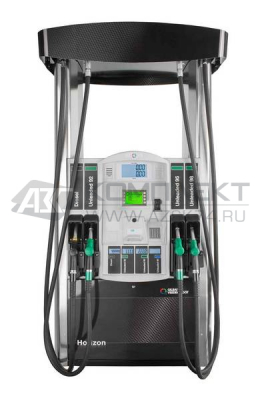


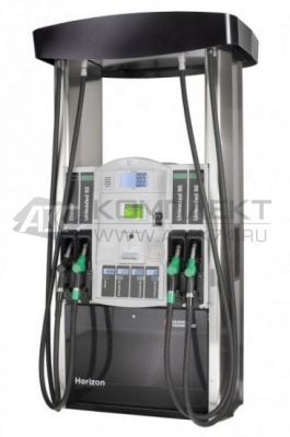
ТРК Gilbarco Horizon 8-0-8 OR STP
Напорная гидравлика,
4 вида топлива,
8 раздаточных рукавов.
0 руб. Оптовая цена
0 руб. Розничная цена
Узнайте цену
Код товара: 12303
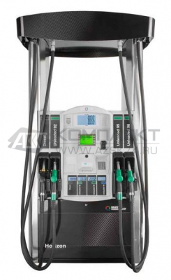


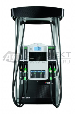
ТРК Gilbarco Horizon 8-4-8 OR
Всасывающая гидравлика,
4 вида топлива,
8 раздаточных рукавов.
0 руб. Оптовая цена
0 руб. Розничная цена
Узнайте цену
Компания ООО «АЗС Комплект» предлагает своим клиентам широкий ассортимент современных высококачественных топливораздаточных колонок (ТРК) Gilbarco Veeder-Root для заправочных станций различных типов:
- Стационарные – классические АЗС
- Блочные АЗС
- Контейнерные АЗС
- Модульные АЗС
- Мобильные АЗС
- Передвижные АЗС
Для каких видов заправочных станций
Топливораздаточные колонки Gilbarco Veeder-Root – это высокое качество и простота в обслуживании. Модельный ряд включает ТРК как для многотопливных заправочных комплексов, так и для ведомственных станций. В зависимости от ваших потребностей вы можете выбрать различные варианты исполнения и дополнительные опции.
Характеристики
Топливораздаточные колонки Gilbarco Veeder-Root характеризуются превосходным качеством сборки и соответствуют высочайшим европейским стандартам, а также имеют ряд преимуществ:
- могут использоваться в широком диапазоне температур (-40. +55 °С);
- работают даже при частых перебоях электроэнергии и колебаниях напряжения в сети;
- обладают устойчивостью к естественному износу и внешним вредоносным воздействиям;
- отличаются длительным эксплуатационным сроком, на протяжении которого сохраняют надлежащую работоспособность.
ТРК Gilbarco Veeder-Root сертифицированы для эксплуатации на территории России и стран СНГ.
В нашем интернет-магазине вы можете заказать и оформить доставку ТРК Gilbarco Veeder-Root.
Высококачественная топливораздаточная колонка – абсолютная гарантия надежной эксплуатации.
Источник: www.azsk74.ru
Топливораздаточные колонки ТРК Gilbarco
ООО «АЗТ СК» предлагает своим клиентам широкий ассортимент современных высококачественных топливораздаточных колонок (ТРК) Gilbarco для заправочных станций различных типов:
- Стационарные – классические АЗС
- Блочные АЗС
- Контейнерные АЗС
- Модульные АЗС
- Мобильные АЗС
- Передвижные АЗС
Топливораздаточные колонки Gilbarco Veeder-Root имеют ряд приимуществ:
- предназначенные для традиционных и альтернативных сортов топлива,
- созданы с использованием гибких инновационных технологий
- ТРК способствуют росту бизнеса, обеспечивая более простое и удобное обслуживание ваших клиентов.
В соответствии с производственными потребностями Вы можете выбрать ТРК Gilbarco Veeder-Root с необходимым набором опций. При производстве топливораздаточных колонок учитывается возможность отпуска различных видов топлива: бензина, дизеля и альтернативных сортов (сжиженного и сжатого газа, Е85, AdBlue, биодизеля).
Варианты исполнения.
- Может быть реализовано в моно- и мультипродуктовом исполнении.
- Оборудование при этом может быть всасывающего или напорного типа.
- Конструкция корпуса колонок также может различаться и быть L-образной, портальной и др.
- ТРК на АЗС могут применяться в качестве вспомогательной станции («сателлита») для реализации высокоскоростного отпуска топлива. Топливораздаточное оборудование предлагается со стандартной (40 и 70 л/мин) или высокой (120 л/мин) производительностью.
- Дополнительное оборудование. В колонки могут устанавливаться поршневой объемомер и прецизионный шнековый измеритель Ecometer. Подвесные шланги для ТРК и механизм их сматывания.
- Система газовозврата (рекуперация паров топлива).
- Мультимедийный дисплей на панели оборудования.
- Встраиваемые модули оплаты топливными и банковскими картами, а также банкнотами, расположенные у ТРК.
- Компания также осуществляет производство колонок с автоматической температурной компенсацией дозы отпускаемого топлива.
Преимущества ТРК Gilbarco Veeder-Root
ТРК Gilbarco Veeder-Root сертифицированы для эксплуатации на всей территории СНГ, они подходят для работы при температуре от -40 до +55 °С. Гарантия на оборудование составляет 18 месяцев с момента его отгрузки или 12 месяцев после установки.
Gilbarco Veeder-Root уделяет большое внимание персональным потребностям каждого клиента, предлагая только высококачественные и надежные топливораздаточные колонки для АЗС с индивидуальными вариантами исполнения и расширенным набором опций. Сотрудничество с Gilbarco Veeder-Root – это увеличение эффективности бизнеса не только в настоящем, но и в будущем за счет использования высококачественного оборудования.
ТРК Gilbarco SK700-II
ТРК Gilbarco Horizon
Источник: xn--80aoj1ae.xn--p1ai
Содержание
- Схема топливораздаточной колонки gilbarco
- Схема топливораздаточной колонки gilbarco
- Подключение ТРК Gilbarco SK 700 к системе GasKit
Схема топливораздаточной колонки gilbarco
Оборудование и программное обеспечение для автоматизации АЗС и нефтебаз
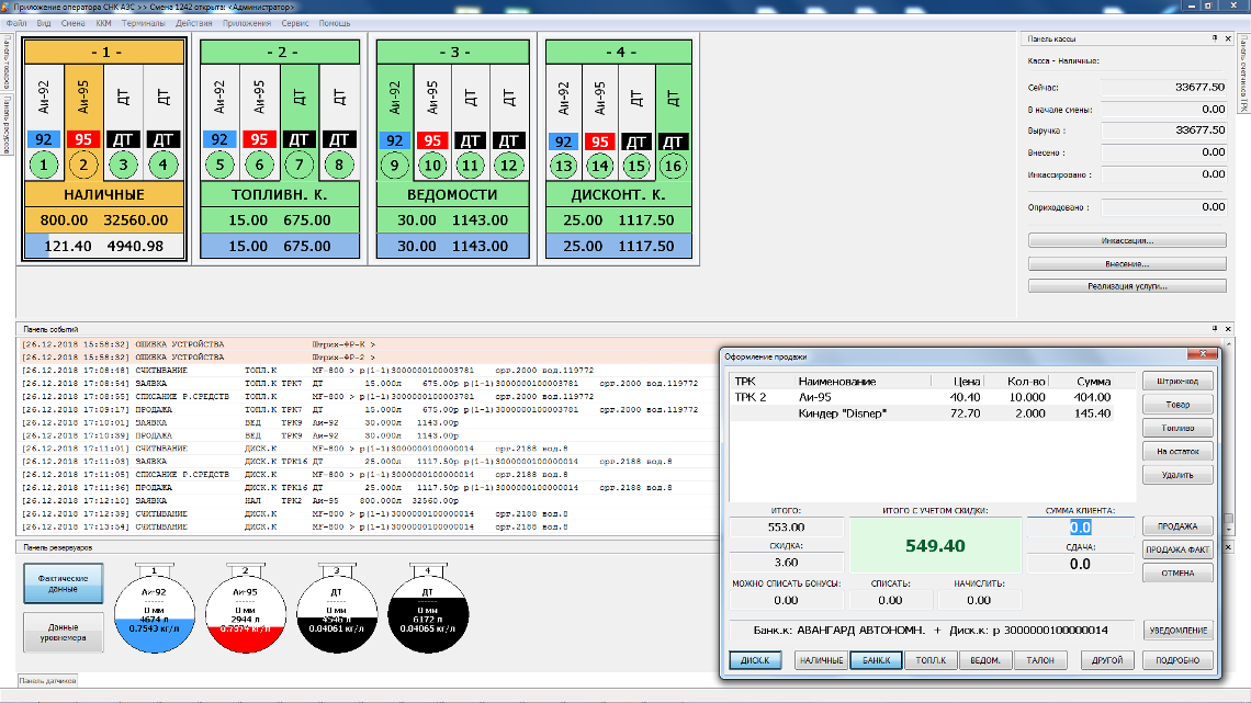
Подключение ТРК Gilbarco к системе управления СНК-АЗС
Управление ТРК Gilbarco осуществляется через СОМ порт персонального компьютера по протоколу «Gilbarco Dispenser Two-Wire Protocol for Third Party Pump Controllers». Для согласования физических интерфейсов необходим преобразователь интерфейсов, например одноканальный « RS 232-20/42ма токовая петля»:

Для подключения ТРК на всех устройствах применены однотипные двухлепестковые разьемы с маркировкой + и -.
Максимальная нагрузочная способность одного канала не более 4-х ТРК.
Подключение со стороны ТРК
На различных топливораздаточных колонках, поддерживающих протокол Two Wire, применяются различные клеммные колодки и номера подключаемых клемм могут быть различны.
Если вы используете одноканальный преобразователь интерфейсов, то все ТРК должны быть подключены в последовательную цепь.
При использовании одноканального варианта преобразователя интерфейсов выход из строя (на разрыв) электрической схемы обработки токового сигнала одной ТРК приводит к отсутствию связи со всеми остальными ТРК.
В случае применения 6-ти канального преобразователя, ТРК можно распределить по отдельным независимым друг от друга каналам.
Настройка системы управления СНК-АЗС
Настройка в программе HWServerConfig :
Запустите программу HWServerConfig . exe , во вкладке Контроллеры создайте Контроллер Gilbarco
- Выберите COM-порт, к которому подключен Контроллер Концентратор или преобразователь интерфейсов.
- Добавьте необходимое количество шлангов.
- При необходимости измените адреса сторон и шлангов.
- Адрес ТРК – устанавливает адрес стороны 1…16
- Шланг – устанавливает адрес шланга на стороне 1…6
- Нажмите кнопку «Сохранить».
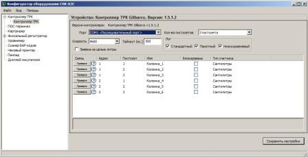
Дополнительные Параметры настройки:
- Блокировка – блокирует опрос шланга
Программирование параметров ТРК Gilbarco SK 700
Внимание: При проведении операций программирования пистолеты
ТРК должны быть повешены.
Программирование параметров электроники ТРК Gilbarco SK 700 производится с помощью сервисной клавиатуры. Клавиатура обычно располагается на внутренней стороне дверцы корпуса электроники ТРК.
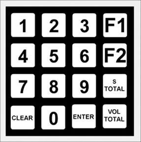
Назначение клавиш сервисного пульта (клавиатуры)
| Клавиша | Назначение |
| 0 — 9 | Цифры |
| F1 | Вход в режим программирования, переход |
| F2 | Выход из режима программирования |
| S TOTAL | Сумма Эта клавиша показывает всю сумму для стороны и сорта. |
| VOL TOTAL | Кол-во — Эта клавиша показывает всё количество для стороны и сорта. |
| ENTER | Ввод значения, подтверждение ввода |
| CLEAR | Удаление (стирание) последнего ввода, выход из режимов TOTAL |
Внимание: Для изменения большинства параметров могут потребоваться
пароли доступа к уровням программирования ТРК.
Рекомендуемая таблица настроек
0 — погружной насос выкл.
1 — погружной насос в ключен
1 — немедленное изменение цены
2 — изменение цены после снятия пистолета
3 — немедленное изменение цены с очисткой дисплея
1 — одна на сторону
2 — отдельная на каждый шланг
Количество дисплеев на стороне:
3 — на 1 стороне два, на 2-й один
4 — на 1-й стороне один, на 2-й два
Описание кодов ошибок Gilbarco SK 700 можно скачать здесь.
Руководство по эксплуатации Gilbarco SK 700 II скачать.
Описание таблицы настроек Gilbarco SK 700 скачать.
Источник
Схема топливораздаточной колонки gilbarco
Программирование параметров ТРК Gilbarco SK 700
Внимание: При проведении операций программирования пистолеты
ТРК должны быть повешены.
Программирование параметров электроники ТРК Gilbarco SK 700 производится с помощью сервисной клавиатуры. Клавиатура обычно располагается на внутренней стороне дверцы корпуса электроники ТРК.
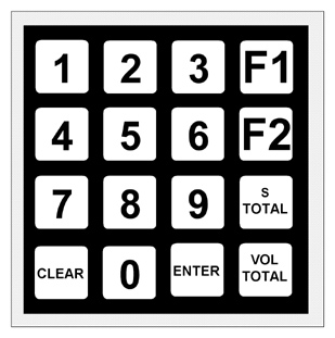
Назначение клавиш сервисного пульта (клавиатуры)
| Номер функции | Номер параметра | Номер подпараметра | Значение параметра | Описание параметра |
| 24 (уровень 1, пароль 2222) | — | — | 1 | TWO WIRE протокол обмена с управляющей системой |
| 40 (уровень 2, пароль 1503) | 1 | 1 | Адрес стороны 1 и 2 | |
| 40 (уровень 2, пароль 1503) | 2 | — | 1,2,4,5 | Скорость обмена:
1 — 5787 (по умолчанию) |
| 47 (уровень 2, пароль 1503) | 2 | — | 1 | Формат передаваемой суммы 5 цифр |
| 40 (уровень 2, пароль 1503) | 5 | — | 2 | 2 — передача обьема в реальном времени |
| 49 (уровень 2, пароль 1503) | 1 | — | 0,1 | |
| 91 (уровень 4, пароль 0128) | 15 | — | 1,2 | |
| 90 (уровень 4, пароль 0128) | — | — | 1,2,3,4 | Количество шлангов на стороне |
| 91 (уровень 4, пароль 0128) | 4 | — | 1,2,3,4 |
| Клавиша | Назначение |
| 0 — 9 | Цифры |
| F1 | Вход в режим программирования, переход |
| F2 | Выход из режима программирования |
| S TOTAL | |
| VOL TOTAL | |
| ENTER | Ввод значения, подтверждение ввода |
| CLEAR | Удаление (стирание) последнего ввода, выход из режимов TOTAL |
Для настройки параметров сопряжения с системой управления GasKit необходимо проконтролировать значение нескольких параметров ТРК Gilbarco SK 700.
Внимание: Для изменения большинства параметров могут потребоваться
пароли доступа к уровням программирования ТРК.
Установка типа канала управления ТРК Gilbarco SK 700
Для управления ТРК Gilbarco SK 700 от системы GasKit необходимо задействовать последовательный канал связи Two Wire.
Данный режим устанавливается на уровне программирования №1.
Для входа в режим программирования №1 и установки типа канала
Two Wire нужно:
- Нажать клавишу «F1»;
- Ввести пароль для уровня №1 «****»;
- Подтвердить ввод пароля «Enter»;
- Ввести код команды «2», «4»;
- Подтвердить код команды «Enter»;
- Ввести режим работы «1»;
- Подтвердить режим работы «Enter»;
Для продолжения программирования нажать клавишу «F1».
Для выхода из режима программирования используется клавиша «F2».
Установка сетевых адресов сторон ТРК Gilbarco SK 700
Изменения параметров приема/передачи данных производятся на уровне программирования №2.
Диапазон для сетевых адресов: 1 – 16.
Для входа в режим программирования №2 и установки сетевых адресов
сторон ТРК Gilbarco SK 700 нужно:
- Нажать клавишу «F1»;
- Ввести пароль для уровня №2 «****»;
- Подтвердить ввод пароля «Enter»;
- Ввести код команды «4», «0»;
- Подтвердить код команды «Enter»;
- Ввести код функции «1»;
- Подтвердить код функции «Enter»;
- Ввести код стороны ТРК «1» или «2»;
- Подтвердить выбор стороны «Enter»;
- Ввести требуемый сетевой адрес ТРК «*»;
- Подтвердить ввод адреса «Enter»;
Для продолжения программирования нажать клавишу «F1».
Установка скорости передачи данных
- Ввести код команды «4», «0»;
- Подтвердить код команды «Enter»;
- Ввести код функции «2»;
- Подтвердить код функции «Enter»;
- Ввести код стороны скорости передачи данных, где
«1» = 5787 bps
«2» = 4800 bps - Подтвердить ввод «Enter»;
Для продолжения программирования нажать клавишу «F1».
Для выхода из режима программирования используется клавиша «F2».
Подключение ТРК Gilbarco SK 700 к системе GasKit
Система управления для АЗС GasKit использует для управления топливораздаточными колонками Gilbarco SK 700 блок сопряжения BS-04-CL6.
Блок сопряжения BS-04-CL6 предназначен для преобразования интерфейса RS232 в интерфейс Current Loop 45mA.
Блок сопряжения BS-04-CL6 позволяет подключить к компьютеру до 12 топливораздаточных колонок (ТРК). При этом могут быть задействованы 6 каналов RS232.
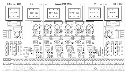
Вид блока сопряжения BS-04-CL6 без крышки:
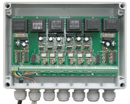
Схема расположения элементов на плате BS-04-CL6:
| Параметр | Значение |
| Число каналов RS232 | 6 |
| Поддерживаемые линии | RxD, TxD |
| Возможность подключения к каждому RS232 нескольких CURRENT LOOP | есть |
| Интерфейс CURRENT LOOP | 45 mA |
| Число каналов CURRENT LOOP | 6 |
| Максимальное число ТРК на каждом канале CURRENT LOOP | 2 |
| Максимальное число ТРК для всего устройства | 12 |
| Максимальное падение напряжения на каждом приемопередатчике ТРК | 3.5 В |
| Возможность работы CURRENT LOOP в активном режиме | есть |
| Возможность работы CURRENT LOOP в пассивном режиме | есть |
| Изолированный источник питания для каждого канала CURRENT LOOP | есть |
| Максимальная скорость передачи данных, не менее | 9600 |
| Потребляемая мощность, не более | 30 Вт |
| Напряжение питания | 220 В |
Подключение кабеля сетевого питания
Подключение сетевого питания осуществляется через разъем Х1. Провод заземления необходимо соединить с клеммой G.
Подключение BS-04-CL6 к компьютеру
Подключение BS-04-CL6 к компьютеру производится через кабели с разъемами DB9 или DB25.
Схема распайки кабеля:
| Контакт на BS-04 | Сигнал | Разъем DB9 | Разъем DB25 |
| R | RxD | 3 | 2 |
| T | TxD | 2 | 3 |
| G | Ground | 5 | 7 |
Схема подключения топливораздаточных колонок Gilbarco SK 700s
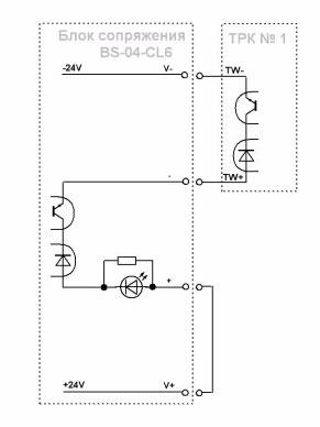
Рекомендуемая схема подключения – одна ТРК – одна петля
CURRENT LOOP – один канал RS232.
Пример подключения одной ТРК Gilbarco SK 700 к одному каналу CURRENT LOOP:
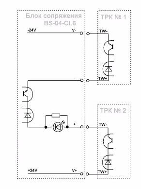
В случае, когда требуется подключить большое количество ТРК и при этом имеется недостаток в COM-портах, допускается подключать к одной петле до 2-х ТРК.
Пример подключения 2-х ТРК Gilbarco SK 700 к одному каналу CURRENT LOOP:
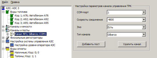
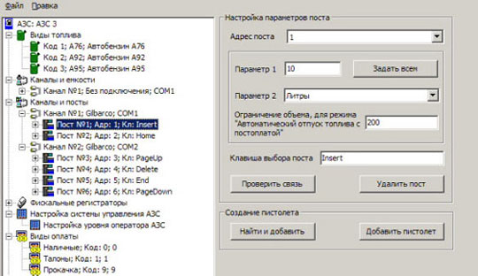
Настройка системы управления GasKit
При настройке системы GasKit необходимо задать следующие параметры:
1.
Для канала управления поста ТРК:
- Номер COM-порта, к которому подключена ТРК.
- Скорость соединения с ТРК. Рекомендуемая скорость 4800.
- Эхо “Есть”.
- Тип создаваемого канала “Gilbarco”.
2.
Для параметров поста:
- Параметр 1 – делитель данных текущей заправки. Зависит от настройки поста и может принимать одно из следующих значений:
- 1 – данные текущей заправки приходят в сотых долях единицы измерения (литра, рубля).
- 10 – данные текущей заправки приходят в тысячных долях единицы измерения (литра, рубля).
- Параметр 2 – определяет единицы измерения данных текущей заправки. Зависит от настройки поста и может принимать одно из следующих значений:
- Литры (0) – данные текущей заправки измеряются в литрах.
- Рубли (1) – данные текущей заправки измеряются в рублях.
Санкт-Петербург Тел.: +7 (812) 324 7202
Факс: +7 (812) 324 7203
—>
E-mail: gasnet@horis.ru
WWW: www.gasnet.ru ![]()
![]()
![]()
![]()
![]()
![]()
![]()
![]()
![]()
© 2004-2021, АО «ХОРИС»
Все права защищены.
Источник
Adblock
detector
- Manuals
- Brands
- GILBARCO VEEDER-ROOT Manuals
- Petrol Station Equipment
- Latitude LS-100
- Owner’s manual
-
Contents
-
Table of Contents
-
Troubleshooting
-
Bookmarks
Quick Links
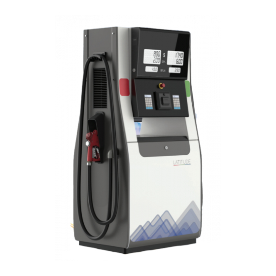
LATITUDE
™
Owner’s Manual
MDE-5422B
Related Manuals for GILBARCO VEEDER-ROOT Latitude LS-100
Summary of Contents for GILBARCO VEEDER-ROOT Latitude LS-100
-
Page 1
LATITUDE ™ Owner’s Manual MDE-5422B… -
Page 2
Computer Programs and Documentation All Gilbarco Inc. and/or Veeder-Root Company computer programs (including software on diskettes and within memory chips) and documentation are copyrighted by, and shall remain the property of, Gilbarco Inc. and/or Veeder-Root Company. Such computer programs and documents may also contain trade secret information. The duplication, disclosure, modification, or unauthorized use of computer programs or documentation is strictly prohibited, unless otherwise licensed by Gilbarco Inc. -
Page 3: Table Of Contents
Table of Contents Table of Contents 1 – Introduction Purpose …………….1-1 Intended Users .
-
Page 4
Table of Contents 6 – Preliminary Steps for Service Preparing for Service …………..6-1 Before Making Service Call . -
Page 5: Introduction
Purpose Introduction 1 – Introduction Purpose This manual provides instructions for safely operating and maintaining LATITUDE™ pumps/dispensers (hereafter referred to as units, unless otherwise specifically stated). IMPORTANT INFORMATION This is the original manual and contains instructions in English. Manuals that are in languages other than English are a translation of the original manual.
-
Page 6: Related Documents
Introduction Related Documents Related Documents Document Number Title GOLD Library MDE-5427 Latitude Installation Manual Latitude MDE-5445 Latitude Service Manual Latitude MDE-5474 Latitude Programming Quick Reference Guide Latitude MDE-5475 Calibration Quick Reference Card LATITUDE™ LS100/200/300 Latitude Latitude™ Multimedia Programming and Service Manual with Latitude MDE-5512 Applause™…
-
Page 7: Important Safety Information
Important Safety Information 2 – Important Safety Information Read the Manual Note: Save this Important Safety Information section in a Read, understand, and follow this manual and any other labels readily accessible location. or related materials supplied with this equipment. If you do not understand a procedure, call a Gilbarco Authorized Service This section introduces the hazards and safety precautions Contractor.
-
Page 8
IMPORTANT: Oxygen may be needed at scene if gasoline has been ingested or inhaled. Seek medical advice immediately. Lockout/Tagout Gilbarco Veeder-Root encourages the recycling of Lockout/Tagout covers servicing and maintenance of machines our products. Some products contain electronics, and equipment in which the unexpected energization or start-up batteries, or other materials that may require special management practices depending on your location. -
Page 9
Important Safety Information Hazards and Actions WARNING Spilled fuels, accidents involving pumps/dispensers, or uncontrolled fuel flow create a serious hazard. Fire or explosion may result, causing serious injury or death. Follow established emergency procedures. The following actions are recommended regarding these hazards: Collision of a Vehicle with Unit Fire at Island Fuel Spill… -
Page 10
Important Safety Information This page is intentionally left blank. Page 2-4 MDE-5422B Latitude™ Owner’s Manual · March 2021… -
Page 11: Supplementary Instructions For European Union (Eu) Countries
Supplementary Instructions for European Union (EU) Countries Sample Declaration of Conformity 3 – Supplementary Instructions for European Union (EU) Countries Dispensing areas of the forecourt must be adequately lit for safety purposes at all times of use. The luminance at ground level and the read-out level of displays must not be less than 100 lux.
-
Page 12: Markings Related To Explosive Atmospheres (Atex) Directive
Supplementary Instructions for Markings Related to Explosive Atmospheres (ATEX) Directive European Union (EU) Countries Markings Related to Explosive Atmospheres (ATEX) Directive Specifications Parameter Value Operating Condition Maximum Surface Temperature 200 °C (392 °F) Three-phase Power Supply (For 3-phase motor only) 400 VAC +10 or — 20% Single-phase Power Supply (For CDM and 1-phase motor) 230 VAC +10 or — 20%…
-
Page 13: Zoning Diagram
Supplementary Instructions for European Union (EU) Countries Zoning Diagram Zoning Diagram Latitude pumps and dispensers are ATEX certified. The dispenser must be installed to not compromise the zones illustrated in Figure 3-1, Figure 3-2 page 3-4, and Figure 3-3 page 3-5.
-
Page 14
Supplementary Instructions for Zoning Diagram European Union (EU) Countries Figure 3-2: Zoning Diagram for LS-100 and LS-200 Island Configuration Island High Hose Island Low Hose Zone 2 Zone 0 Zone 1 Page 3-4 MDE-5422B Latitude™ Owner’s Manual · March 2021… -
Page 15
Supplementary Instructions for European Union (EU) Countries Zoning Diagram Figure 3-3: Zoning Diagram for LS-300 Configuration Hazardous Area For 4 Grade Models Hazardous Area For 4 Grade Models Without Hose Retraction Feature With Hose Retraction Feature External Zoning Zone 2 Zone 0 Zone 1 MDE-5422B Latitude™… -
Page 16: Material Compatibility
Supplementary Instructions for Material Compatibility European Union (EU) Countries Material Compatibility IMPORTANT INFORMATION GVR dispensers are suitable for temporary external and internal exposure to petrol and associated vapors, ethanol-blended fuels, diesel, biodiesels, LPG and associated vapors, water with minimal salt content, mild cleaning agents, AdBlue (DEF), ®…
-
Page 17: Latitude Components
Dispenser Overview Latitude Components 4 – Latitude Components Dispenser Overview This chapter provides a description of the Latitude unit and its components. Figure 4-1: Latitude Pump (ii) Front View Side View Sl. No. Menu Sl. No. Menu Motor Pulser Suction Unit Inlet Filter Junction Box (J-Box) Spin on Filter…
-
Page 18
Latitude Components Dispenser Overview Figure 4-2: Latitude Dispenser Front View Side View Sl. No. Menu Sl. No. Menu Shear Valve Inlet Pipe Vapor Recovery Pump Valve Junction Box Pulser Swivel Inlet Filter Side Flow Indicator Spin on Filter Hose Meter Reed Sensor Meter Manifold Electronics Zone… -
Page 19: Common Functions
Common Functions Latitude Components Common Functions This section provides information on the common functions of the Latitude unit. Keypad The Latitude dispenser keypad has a total of 20 keys that include alphanumeric, functional, and hot preset keys. Figure 4-3: Alphanumeric Keypad Using Keypad The following functions can be performed using the keypad: •…
-
Page 20: Pin Of Each Level Command
Latitude Components PIN of each Level Command PIN of each Level Command Parameters are set using the keypad. Enter a four-digit PIN code to use all programming functions and levels. The PIN can be changed from the respective menu or from menus with higher rights.
-
Page 21: Vapor Recovery And Monitoring
Premium Features Latitude Components Color Color Swatch White • Skylight LED Strips The Skylight LED Strips are used for image enhancements. These strips can be configured have single static color as they do not change color based on FP status. The strip color is configured, from the above stated color options, at factory.
-
Page 22: Hose Retraction
Latitude Components Premium Features Hose Retraction With this feature, minimal effort is required to pull the hose from the retraction system, thereby enabling the attendant to perform hassle-free fuel deliveries. A typical hose reach ranges between 3-3.5 meters. However, with this feature the hose reach can extend up to 4.5 meters.
-
Page 23: Latitude Operation
Working Principle Latitude Operation 5 – Latitude Operation Working Principle Figure 5-1 illustrates the working principle of the Latitude pump. Pump operates on standalone or console-controlled mode. Figure 5-1: Work Flow Diagram of Latitude Pump Motor Electronic System Switch Pulser Nozzle Boot J-box Solenoid Valve…
-
Page 24: Self-Contained Pump
Latitude Operation Working Principle Self-contained Pump The following steps describe the functioning of a self-contained pump: Fuel enters through the pump inlet pipe passing through a strainer. If the pressure is too high, the fuel flows through a bypass valve and recirculates. The pump has an air separation system.
-
Page 25
Working Principle Latitude Operation Pull out the nozzle horizontally and dispense the fuel. Figure 5-4: Pulling Out Nozzle • After Fueling To place back the nozzle in to the nozzle boot after dispensing the fuel, proceed as follows: Push the nozzle horizontally into the nozzle boot after dispensing the fuel. Figure 5-5: Pushing Nozzle Horizontally (ii) Dispensing the Fuel… -
Page 26: Operating Pump/Dispenser
Latitude Operation Working Principle Rest the nozzle on the cradle and release. Figure 5-7: Resting Nozzle on Cradle Operating Pump/Dispenser To operate the pump/dispenser, proceed as follows: Fill the tank. Insert the nozzle pipe deep into the car filler and position the nozzle so that it does not slip out [see Figure 5-8 (i)].
-
Page 27: Dispenser Start-Up
Dispenser Start-up Latitude Operation Dispenser Start-up The following section describes the procedure to start a dispenser: Initializing the Dispenser Power on the dispenser to enter the initialization state. Total Sale, Volume, and Price Per Unit (PPU) displays indicate the software version. The text on the keypad LCD indicates the version of the system.
-
Page 28
Latitude Operation Dispenser Start-up Set Volume Preset Dispenser is in the IDLE state. Nozzles for that side are in the boot. Press Volume and then press the number key to set the value. You can also use a fixed preset key (P1, P2, P3 or P4) and then press ENTER. -
Page 29: View Sale Totalizer
Dispenser Start-up Latitude Operation View Sale Totalizer To view the Sale Totalizer, proceed as follows: Ensure that the nozzles for that side are in the boot. Press TOT to see the TOTALIZER string on the 16 X 2 Liquid Crystal Display (LCD) display [see Figure 5-11 (i)].
-
Page 30: View Volume Totalizer
Latitude Operation Dispenser Start-up Figure 5-11: Setting the Sale Totalizer (iii) (ii) (iv) (vi) View Volume Totalizer To view the Volume Totalizer, proceed as follows: Ensure that the nozzles for that side are in the boot. on Press TOT to see the TOTALIZER string on the 16 X 2 LCD display [see Figure 5-12 (i) page 5-9].
-
Page 31
Dispenser Start-up Latitude Operation Repeat steps for the remaining nozzles and press the corresponding key to view the volume totalizer. To exit the Totalizer menu, press F1. To exit the Keypad menu, press F2. When F2 is pressed, the keypad displays the string “READY”. -
Page 32: Setting Parameters
Latitude Operation Setting Parameters Setting Parameters IMPORTANT INFORMATION A parameter or option determines the settings selected for that function. A default option will usually be programmed into the unit but these options can be modified as per the requirements. Note: Ensure that the dispenser is in the IDLE state and all the nozzles are in the boot. The measurement system must be metric.
-
Page 33: User Menu Mode
Setting Parameters Latitude Operation User Menu Mode The following diagram shows the procedure for entering User Menu mode and viewing the menu and sub-menu: Press F1 followed by key 1 to enter in to the User Menu mode. Enter the four-digit password and press ENTER. The DATE&TIME menu is displayed. Press up or down arrow keys to scroll through the menus [see Figure 5-13 (v) and (vi)].
-
Page 34: User Menu Mode For Setting The Price
Latitude Operation Setting Parameters Select the CUM VOL sub-menu by pressing the ENTER key. On first line of the LCD display, N1 is Nozzle 1 and S1 is Side 1. The second line shows cumulative volume dispensed [see Figure 5-14 (iii)].
-
Page 35
Setting Parameters Latitude Operation Press ENTER to see PPU CHANGE VIEW mode. Figure 5-16: PPU CHANGE VIEW Mode Select Side and press ENTER. Select Grade and press ENTER. The user can now see the current PPU value. Press ENTER to see PPU CHANGE EDIT mode. Figure 5-17: PPU CHANGE EDIT Mode After pressing the ENTER key, the current PPU value will start blinking. -
Page 36: Command Code Mode
Latitude Operation Setting Parameters Figure 5-18: PPU CHANGE SET Mode on Press the F1 key to enter the PPU CHANGE menu. Repeat steps page 5-13 page 5-13 to enter the prices for other nozzles or grades. Upon completing any menu editing process, press F2 to reboot the pump. The pump returns to the IDLE state after the reboot.
-
Page 37
Setting Parameters Latitude Operation Parameter 20: Set PPU Values Command code 20 is entered in Level 1 programming to set or change the PPU values. The following is the layout and description of the digit position for this programming feature: Keypad: ENTER Side Sale… -
Page 38
Latitude Operation Setting Parameters Keypad: 2 — Select Side 2 Keypad: ENTER Keypad: 2 — Select Grade 2 Keypad: ENTER Page 5-16 MDE-5422B Latitude™ Owner’s Manual · March 2021… -
Page 39
Setting Parameters Latitude Operation Keypad: 2 — Select Level 2 Keypad: ENTER Keypad: 1099 — New PPU Value Keypad: ENTER Press F1 for additional programming or F2 to exit programming. MDE-5422B Latitude™ Owner’s Manual · March 2021 Page 5-17… -
Page 40
Latitude Operation Setting Parameters Parameter 24: Set Mode of the Operation Security Code — 2222 (for Level 1 programming) Command code 24 is entered in Level 1 programming to set dispenser operating mode. The operation mode setting determines how the dispenser is controlled remotely or if it operates without external control. -
Page 41
Setting Parameters Latitude Operation Keypad: 2 — Select Two-wire Mode Keypad: ENTER Press F1 key for additional programming or F2 key to exit programming. Flow rate (key 5) When in standalone mode (CC24=2), press 5 to see the flow rate in the money display and the current dispensed volume in the volume display. -
Page 42
Latitude Operation Setting Parameters Parameter 25: Set the Allocation Volume Command code 25 is entered in level 1 programming to set grade allocation volume. The following is the layout and description of the allocation programming display: Note: The decimal point position may change in the main volume display depending on its location from the display decimal point programming. -
Page 43
Setting Parameters Latitude Operation Keypad: ENTER Keypad: 10000 — Allocation Amount Keypad: ENTER Press F1 for additional programming or F2 to exit programming. MDE-5422B Latitude™ Owner’s Manual · March 2021 Page 5-21… -
Page 44
Latitude Operation Setting Parameters Parameter 31: Set the Amount Limits Command Code 31 is entered in Level 1 programming to set side and grade allocation amount. The following is the layout and description of the allocation programming display: Note: The decimal point position may change in the main volume display depending on its location from the display decimal point programming. -
Page 45
Setting Parameters Latitude Operation Keypad: ENTER Keypad: 90000 — Allocation Amount Keypad: ENTER Press F1 key for additional programming or F2 key to exit programming. Level 2 Commands Parameter 40: Set Communication Parameters for Security Code — XXXX (for Level 2 programming) Command code 40 is entered in Level 2 programming to access two-wire parameters. -
Page 46
Latitude Operation Setting Parameters The available options for this command code are listed in the following table: Function Code Two-wire Parameters 1 — Default Two-wire ID Two-wire Baud Rate Parameter 40.1: Set Two-Wire ID Function Code 1 is entered to set the dispenser ID number. The address range is from 1 to 16 for two-wire and 1 to 8 for Automatic Transfer Control Logic (ATCL). -
Page 47
Setting Parameters Latitude Operation — Set Two-Wire ID Keypad: ENTER — Select Side B Keypad: ENTER Keypad: ENTER Address 15 Keypad: 15 — Enter Keypad: ENTER Press F1 for additional programming or F2 to exit programming. MDE-5422B Latitude™ Owner’s Manual · March 2021 Page 5-25… -
Page 48
Latitude Operation Setting Parameters Parameter 40.2: Set Two-wire Baud Rate The following is the layout and description of this programming feature: Sale Code Volume The available options for this command code are listed in the following table: Code Baud Rate 1 — Default 5787 bps (two-wire) 4800 bps (two-wire/ATCL) -
Page 49
Setting Parameters Latitude Operation Keypad: ENTER Keypad: 2 — Select Baud Rate 2 Keypad: ENTER Press F1 for additional programming or F2 to exit programming. MDE-5422B Latitude™ Owner’s Manual · March 2021 Page 5-27… -
Page 50
Latitude Operation Setting Parameters Parameter 42: Lighted Canopy Settings Command Code 42 provides functions to configure the canopy features. The following is the layout and description of the allocation programming display: Function code Sale Code Volume The available options for configuring the canopy features are: Function Code Description Set the color to indicate that Fueling Point is available for fueling. -
Page 51
Setting Parameters Latitude Operation Keypad: 5 — Configure the canopy color to indicate that Fueling Point is available for fueling Keypad: ENTER Keypad: 1 — Configure the color to Red. Keypad: ENTER MDE-5422B Latitude™ Owner’s Manual · March 2021 Page 5-29… -
Page 52
Latitude Operation Setting Parameters The canopy color can be configured as follows: Value Color Orange Yellow Green (Default) Blue Purple White White 5000K Press F1 key for additional programming or F2 key to exit programming. CC42FC6 Keypad: 42 — Configure lighted canopy settings Keypad: ENTER Keypad: 6 — Configure the canopy color to indicate that Fueling Point is busy Page 5-30… -
Page 53
Setting Parameters Latitude Operation Keypad: ENTER Keypad: 3 — Configure the color to Yellow Keypad: ENTER The canopy color can be configured as follows: Value Color Red (Default) Orange Yellow Green Blue Purple White White 5000K Press F1 key for additional programming or F2 key to exit programming. MDE-5422B Latitude™… -
Page 54
Latitude Operation Setting Parameters CC42FC7 Keypad: 42 — Configure lighted canopy settings Keypad: ENTER Keypad: 7 — Enable or disable the Fueling Point. Keypad: ENTER Page 5-32 MDE-5422B Latitude™ Owner’s Manual · March 2021… -
Page 55
Setting Parameters Latitude Operation Keypad: 1 — Enter the Strip Number or FP Number to be enabled or disabled. This value ranges from 1 to 4. Keypad: ENTER When enabled, it is set to the same color that is configured to Keypad: 1 — Enable FP. -
Page 56
Latitude Operation Setting Parameters CC42FC8 Keypad: 42 — Configure lighted canopy settings Keypad: ENTER Keypad: 8 — Turn OFF all perimeter LEDs Keypad: ENTER Page 5-34 MDE-5422B Latitude™ Owner’s Manual · March 2021… -
Page 57
Setting Parameters Latitude Operation Keypad: 0 — To turn OFF all the perimeter LEDs. To turn ON the perimeter LEDs, value is set to 1. Keypad: ENTER Press F1 key for additional programming or F2 key to exit programming. CC42FC9 Keypad: 42 — Configure lighted canopy settings Keypad: ENTER MDE-5422B Latitude™… -
Page 58
Latitude Operation Setting Parameters Keypad: 9 — Turn OFF both Skylight LEDs Keypad: ENTER Keypad: 0 — To turn OFF both Skylight LEDs. To turn ON both Skylight LEDs, value is set to 1. Keypad: ENTER Press F1 key for additional programming or F2 key to exit programming. Page 5-36 MDE-5422B Latitude™… -
Page 59
Setting Parameters Latitude Operation CC42FC10 Keypad: 42 — Configure lighted canopy settings Keypad: ENTER Keypad: 10 — Configure Skylight color Keypad: ENTER MDE-5422B Latitude™ Owner’s Manual · March 2021 Page 5-37… -
Page 60
Latitude Operation Setting Parameters Keypad: 1 — To configure the color to Red. Keypad: ENTER The Skylight color can be configured as follows: Value Color Orange Yellow Green Blue Purple White White 5000K Press F1 key for additional programming or F2 key to exit programming. Parameter 83 Function Code 14: Enable EVR LED Component Command Code 83 Function Code 14 is entered to enable EVR LED component. -
Page 61
Setting Parameters Latitude Operation The available options for EVR LED component on Combi Display are as follows: Value Description Disabled Enabled (LED show state of VRM) Enabled (LED show state of VR Italy) Keypad: 83 — To enable EVR LED component Keypad: ENTER Keypad: 14 — Enable Indicator LED on Combi Display Keypad: ENTER… -
Page 62
Latitude Operation Setting Parameters Keypad: 2 — Enable EVR LED component Press F1 key for additional programming or F2 key to exit programming. Parameter 40 Function Code 20: Configure IP address for communication Command Code 40 Function Code 20 is used to configure IP address for communication. Consider the example of configuring IP address for communication. -
Page 63
Setting Parameters Latitude Operation Keypad: ENTER Keypad: ENTER Keypad: 172 — Configure first part of IP address for communication Keypad: ENTER Keypad: 2 — Configure second part of IP address for communication MDE-5422B Latitude™ Owner’s Manual · March 2021 Page 5-41… -
Page 64
Latitude Operation Setting Parameters Keypad: ENTER Similarly, third and fourth part of the IP address can be configured as 100 and 005, respectively. Press F1 key for additional programming or F2 key to exit programming. Parameter 40 Function Code 21: Configure Subnet Mask Command Code 40 Function Code 21 is used to configure the subnet mask. -
Page 65
Setting Parameters Latitude Operation Keypad: ENTER Keypad: ENTER Keypad: 255 — First part of Subnet Mask Keypad: ENTER Keypad: 2 — Configure second part of the Subnet Mask. MDE-5422B Latitude™ Owner’s Manual · March 2021 Page 5-43… -
Page 66
Latitude Operation Setting Parameters Keypad: ENTER Similarly, third and fourth part of the Subnet Mask can be configured as 255 and 000, respectively. Press F1 key for additional programming or F2 key to exit programming. Parameter 19 Function Code 1: Configure Grade ID per Fueling Point Keypad: 19 — Configure Multimedia Parameters Keypad: ENTER Page 5-44… -
Page 67
Setting Parameters Latitude Operation Keypad: ENTER Keypad: ENTER Keypad: ENTER Keypad: 101 — Grade ID for FP 1 Grade 1 Keypad: ENTER MDE-5422B Latitude™ Owner’s Manual · March 2021 Page 5-45… -
Page 68
Latitude Operation Setting Parameters Keypad: 2 — Configure FP 1 for Grade 2 Keypad: ENTER Keypad: 102 — Grade ID for FP 1 Grade 2 Similarly, Grade ID for remaining grades for FP 1 can be configured. Now, consider the example of configuring Grade ID for FP 2 Keypad: ENTER Keypad: ENTER… -
Page 69
Setting Parameters Latitude Operation Keypad: 2 — Configure Grade ID for FP 2 Grades Keypad: ENTER Keypad: ENTER Keypad: 101 — Grade ID for FP 2 Grade 1 Keypad: ENTER MDE-5422B Latitude™ Owner’s Manual · March 2021 Page 5-47… -
Page 70
Latitude Operation Setting Parameters Keypad: 2 — Configure Grade ID for FP 2 Grade 2 Keypad: ENTER Keypad: 102 — Grade ID for FP 2 Similarly, Grade Id for remaining grades for each FP can be configured. Press F1 key for additional programming or F2 key to exit programming. Parameter 19 Function Code 2: Configure Multimedia Pump ID per Fueling Point Command Code 19 Function Code 2 is entered to configure Multimedia (MM) Pump ID for each Fueling Point (FP). -
Page 71
Setting Parameters Latitude Operation Keypad: ENTER Keypad: 2 — Configure MM Pump ID Keypad: ENTER Keypad: ENTER MDE-5422B Latitude™ Owner’s Manual · March 2021 Page 5-49… -
Page 72
Latitude Operation Setting Parameters Keypad: 011 — Pump ID for FP 1 Keypad: ENTER Keypad: 2 — Configure Pump ID for FP 2 Keypad: ENTER Keypad: 022 — Pump ID for FP 2 Similarly, Pump ID for FP 3 and FP 4 can be configured as 203 and 044, respectively. Press F1 key for additional programming or F2 key to exit programming. -
Page 73
Setting Parameters Latitude Operation Level 3 Commands: Security Code XXXX Parameter 85: Comma/Decimal Point Digit Settings Function Code Sale Digits After Decimal Point Volume The following table lists the function codes for Command Code 85: Function Code Description Set Money Decimal Point for Display Set Volume Decimal Point for Display Set PPU Decimal Point for Calculation Set PPU Decimal Position for Display… -
Page 74
Latitude Operation Setting Parameters Select Function Code 1 (Setting Money Decimal Point for Display) Keypad: 1 — Keypad: ENTER One Digit after Decimal Keypad: 2 — Keypad: ENTER Page 5-52 MDE-5422B Latitude™ Owner’s Manual · March 2021… -
Page 75
Setting Parameters Latitude Operation CC85 FC2 Set Decimal Points Keypad: 85 — Keypad: ENTER Select Function Code 2 (Setting Volume Decimal Point for Display) Keypad: 2 — Keypad: ENTER Two Digits after Decimal Keypad: 3 — MDE-5422B Latitude™ Owner’s Manual · March 2021 Page 5-53… -
Page 76
Latitude Operation Setting Parameters Keypad: ENTER CC85FC3 Note: The value set for CC85 FC3 and CC85 FC4 must always be the same. This implies that every time the user changes the value for CC85 FC3, they need to set the value for CC85 FC4 as well. -
Page 77
Setting Parameters Latitude Operation One Digit after Decimal Keypad: 2 — Keypad: ENTER CC85 FC4 Set Decimal Points Keypad: 85 — Keypad: ENTER Keypad: ENTER MDE-5422B Latitude™ Owner’s Manual · March 2021 Page 5-55… -
Page 78
Latitude Operation Setting Parameters Select Function Code 4 (Setting PPU Decimal Point for Display) Keypad: 4 — Keypad: ENTER One Digit after Decimal Keypad: 2 — Keypad: ENTER Press F1 for additional programming or F2 to exit programming. Notes: 1) After changing any parameter, press F2 to set that value in the database and the pump will reboot. -
Page 79
Setting Parameters Latitude Operation Parameter 75: Configure Fuel Density Command Code 75 provides functions to configure fuel density of each grade. The following is the layout and description of the allocation programming display: Grade Sale Fuel Density Volume Value The available options for configuring fuel density for each grade are as follows: Function Code Description Configure fuel density for grade 1. -
Page 80
Latitude Operation Setting Parameters Keypad: 1 — Configure the fuel density for Grade 1. The grade value ranges from 1- 6. Keypad: ENTER Keypad: 3 — Enter the Fuel Density Keypad: ENTER Keypad: 2 — To configure the fuel density for Grade 2. Page 5-58 MDE-5422B Latitude™… -
Page 81
Setting Parameters Latitude Operation Keypad: ENTER Keypad: 6 — Enter the Fuel Density Keypad: ENTER Keypad: 3 — Configure the fuel density for Grade 3 Keypad: ENTER MDE-5422B Latitude™ Owner’s Manual · March 2021 Page 5-59… -
Page 82
Latitude Operation Setting Parameters Keypad: 7 — Enter the Fuel Density Keypad: ENTER Press F1 key for additional programming or F2 key to exit programming. Parameter 80: Configure Maximum Fuel Flow Rate Command Code 80 provides functions to configure maximum fuel flow rate for each grade. The default value for flow rate is 70 lpm. -
Page 83
Setting Parameters Latitude Operation Consider the example of configuring fuel flow rate for Side 1 Nozzle 1 and Side 2 Nozzle 1. Keypad: 80 — Configure maximum Fuel Flow Rate Keypad: ENTER Keypad: ENTER MDE-5422B Latitude™ Owner’s Manual · March 2021 Page 5-61… -
Page 84
Latitude Operation Setting Parameters Keypad: 40 — Configure maximum Fuel Flow Rate Keypad: ENTER Keypad: ENTER Keypad: 2 — Configure maximum Fuel Flow Rate for Side 2 Nozzle 1 Keypad: ENTER Page 5-62 MDE-5422B Latitude™ Owner’s Manual · March 2021… -
Page 85
Setting Parameters Latitude Operation Keypad: ENTER Keypad: 40 — Configure maximum Fuel Flow Rate Keypad: ENTER Press F1 key for additional programming or F2 key to exit programming. Level 4 Parameter 91 Function Code 14: Enable Vapor Recovery and Monitoring Feature Command Code 91 Function Code 14 is entered to enable Vapor Recovery and Monitoring (VRM) feature. -
Page 86
Latitude Operation Setting Parameters Keypad: 91 — Enable Vapor Recovery feature Keypad: ENTER Keypad: 14 — Enable Vapor Recovery feature Keypad: ENTER Keypad: 2 — Enable VRC Page 5-64 MDE-5422B Latitude™ Owner’s Manual · March 2021… -
Page 87
Setting Parameters Latitude Operation Note: To enable VRM, enter 3 instead of 2. Press F1 key for additional programming or F2 key to exit programming. Parameter 91 Function Code 43: Enable VRM Configurable Duration Command Code 91 Function Code 43 is entered to enable VRM configurable duration. The following is the layout and description of the allocation programming display: Function Code Sale… -
Page 88
Latitude Operation Setting Parameters Keypad: 43 — VRM configurable duration Keypad: ENTER Keypad: 2 — Enable VRM configurable duration Parameter 91 Function Code 47: Enable Multimedia Client over Ethernet Command Code 91 Function Code 47 is entered to enable Multimedia (MM) Client over Ethernet. -
Page 89
Setting Parameters Latitude Operation Consider the example of enabling MM Client over Ethernet. Keypad: 91 — Enable MM Client over Ethernet Keypad: ENTER Keypad: 47 — Enable or disable MM Keypad: ENTER Keypad: 4 — Enable MM over Ethernet Press F1 key for additional programming or F2 key to exit programming. MDE-5422B Latitude™… -
Page 90
Latitude Operation Setting Parameters Parameter 91 Function Code 50: Configure Ping Timeout for MM Client Command Code 91 Function Code 50 is entered to configure ping timeout for multimedia connection. The value for timeout ranges from 1-200 and is multiple of 100 ms. The following is the layout and description of the allocation programming display: Function Code Sale… -
Page 91
Setting Parameters Latitude Operation Keypad: ENTER Note: The Ping Timeout Duration can be configured based on the requirement. The default value is 50. Press F1 key for additional programming or F2 key to exit programming. Parameter 91 Function Code 51: Configure Port Number for Socket Connection Command Code 91 Function Code 51 is entered to configure Port Number for Socket Connection. -
Page 92
Latitude Operation Setting Parameters Keypad: 51 — Configure Port Number for Socket Connection Keypad: ENTER Note: The Port Number for Socket Connection can be configured based on the requirement. Parameter 91 Function Code 52: Configure Number of Clients to Connect Command Code 91 Function Code 52 is entered to configure the number of clients to connect. -
Page 93
Setting Parameters Latitude Operation Consider the example of configuring the number of clients to connect. Keypad: 91 — Configure Number of Clients to Connect Keypad: ENTER Keypad: 52 — Configure Number of Clients to Connect Keypad: ENTER Keypad: 1 — Number of Client to Connect Note: The Number of Clients to Connect can be configured based on the requirement. -
Page 94: Parameter Settings Menu
Latitude Operation Setting Parameters Parameter Settings Menu The following table provides information about the three levels of operation: Operation Level Description Indicates the basic operational level, which includes all features that are typically handled during Level 1 day-to-day usage of the pump/dispenser. Level 2 Incorporates the entire menu that is available in Level 1 and offers some additional menus to handle the operation of the pump, which is normally controlled by the management team of the oil company…
-
Page 95
Setting Parameters Latitude Operation Edit Access Level 0 Level 1 Level 2 Sr. # Menu Sub Menu Sub Menu Sub Menu (Site) (Service) (Engineer) LOGS Transaction NZ:x Sidex DD.MM.YY HH:MM Volume : xx Amount : xx Rate:xxxx Pr Type:x Pr Vol:x… -
Page 96
Latitude Operation Setting Parameters Edit Access Level 0 Level 1 Level 2 Sr. # Menu Sub Menu Sub Menu Sub Menu (Site) (Service) (Engineer) Pump SN CPU SN BB SN Disp1 SN Disp2 SN Disp3 SN Disp4 SN SERIAL NUMBER KP1 SN KP2 SN KP3 SN… -
Page 97
Setting Parameters Latitude Operation Edit Access Level 0 Level 1 Level 2 Sr. # Menu Sub Menu Sub Menu Sub Menu (Site) (Service) (Engineer) CONFIG HL01: RECEIPT HL02: HL03: HL04: HL05: HL06: HL07: HL08: HL09: HL10: FL1: FL2: FL3: FL4: FL5: FT1: FT2:… -
Page 98: Pump Configuration
Latitude Operation Setting Parameters Pump Configuration The pump can be configured in two ways: • Universal Serial Bus (USB) • Manually using CC Configuring the Pump using USB To configure the pump using USB, proceed as follows: Note: Ensure that the USB/Pen Drive being used has following specifications when using it on Latitude: Brand Toshiba, Sony, Kingston, Transcend…
-
Page 99
Setting Parameters Latitude Operation Configuring Pump Manually Using CC Setting Up Pump Configuration Type To set up pump configuration type, proceed as follows: Press F1 to open the CC menu and press 1 to enter the CC. press Enter the password and ENTER. -
Page 100: Date And Time
Latitude Operation Setting Parameters Date and Time To set date and time, proceed as follows: Press F1 to open the CC menu and press 2 to enter the CC. Enter Level 4 password “XXXX” and press ENTER. (CC60FC1=HHMM): Press F1 > Enter CC 60 > ENTER > 1 > ENTER > Enter 2-digit hours and 2-digit minutes >…
-
Page 101: Preliminary Steps For Service
Preparing for Service Preliminary Steps for Service 6 – Preliminary Steps for Service This section provides instructions for collecting information on any unit-related problems that a Gilbarco-trained ASC or Customer Specified Contractor (CSC) will require for servicing. Providing complete information can shorten the time that the ASCs/CSCs spend in troubleshooting and enable them to have the correct parts required for service.
-
Page 102: Replacing Parts
Preliminary Steps for Service Replacing Parts Replacing Parts Use only genuine Gilbarco replacement parts and retrofit kits on your unit. WARNING Use only Gilbarco replacement parts and retrofit kits. Non-Gilbarco replacement parts may create safety hazards and violate local regulations. Gilbarco replacement parts are required to maintain warranty.
-
Page 103: Latitude Pump/Dispenser Maintenance
General Safety Considerations Latitude Pump/Dispenser Maintenance 7 – Latitude Pump/Dispenser Maintenance This chapter provides information on the following aspects of pump/dispenser maintenance: • “Inspecting Pump/Dispenser Periodically” • “Periodic Maintenance Requirements” page 7-10 • “Special Maintenance Instructions” page 7-10 CAUTION Do not open the electronics cabinet to change paper, to remove cash acceptor cassettes, or to perform any other tasks when it is raining.
-
Page 104: General Inspections
Latitude Pump/Dispenser Maintenance Inspecting Pump/Dispenser Periodically Safety Warnings You are performing inspections and maintenance in a potentially dangerous environment of flammable fuels/vapors and high voltage. Follow all safety precautions in “Important Safety Information” page 2-1 to prevent injury when inspecting a unit at the islands. WARNING You are performing inspections and maintenance in a potentially dangerous environment of flammable fuels/vapors and high voltage.
-
Page 112: Periodic Maintenance Requirements
Latitude Pump/Dispenser Maintenance Periodic Maintenance Requirements Periodic Maintenance Requirements Cleaning Filter Cleaning the filter regularly will prevent it from clogging and improves flow rate. For more information, refer to “Special Maintenance Instructions”. Cleaning the Printer Cleaning the printer regularly may help print quality and increase the life-span of the printer. Special Maintenance Instructions Cleaning and Detailing Unit To clean and detail the unit, use the following items:…
-
Page 113
Special Maintenance Instructions Latitude Pump/Dispenser Maintenance Routine Cleaning To clean the unit, proceed as follows: Note: Perform routine cleaning weekly or as required. Place safety cones or other devices to barricade the units being cleaned. Wear safety glasses and flexible rubber gloves. In the empty spray bottle, prepare a mixture of one part concentrated Simple Green cleaner to 10 parts water. -
Page 114: Changing The Receipt
Latitude Pump/Dispenser Maintenance Special Maintenance Instructions Changing the Receipt Paper loading To load the paper in the printer, at the time of installation or refilling the paper, proceed as follows: Note: To get the best quality print, ensure that thermal paper used is as per recommended specifications.
-
Page 115
Special Maintenance Instructions Latitude Pump/Dispenser Maintenance Unlock the printer head by pulling it out and then insert the paper in the space provided between the printer head and the paper roller. Note: PAPER FEED command will not work if the printer head is not locked properly and in the absence of the paper. -
Page 116
Latitude Pump/Dispenser Maintenance Special Maintenance Instructions This page is intentionally left blank. Page 7-14 MDE-5422B Latitude™ Owner’s Manual · March 2021… -
Page 117: Troubleshooting
Troubleshooting 8 – Troubleshooting Error Possible Causes Recommended Actions Pump does not start Pump is in an error state Check if the keypad shows any errors. To after nozzle lift resolve the error, contact the Gilbarco ASC. Mains power failure Confirm mains cable is connected according to the connection diagram provided in the manual and mains is ON.
-
Page 118
Troubleshooting Error Possible Causes Recommended Actions Noisy Operation Crate not bolted down properly Check that all nuts are properly tightened and the bolts are properly grouted as specified in the manual. Too much belt tension or misalignment Ensure proper adjustment of belt tension and of pulleys alignment of pulleys. -
Page 119
Troubleshooting Error Possible Causes Recommended Actions Vapor Recovery Loose connection with Vaporix2 Board • Check RS-422 adapter cable connections. Monitoring System ~OR~ • Identify if there is any cable breakage. stops (Vaporix stops) System stops to prevent leakage • Repair Vapor Recovery with Service Terminal and Gas Meter. -
Page 120
Troubleshooting This page is intentionally left blank. Page 8-4 MDE-5422B Latitude™ Owner’s Manual · March 2021… -
Page 121
Index Index safety hazards shear valve Air free solenoid valve Airborne Noise Emissions static electricity fueling hazards Air-free strainer alphanumeric ATEX trip hazard breakaway coupling breakaway whip hose Zoning Diagram bypass valve 7-10 car polish Customer Preset downtime Dual Ecometer 5-78 Error Codes filter… -
Page 122
© 2021 Gilbarco Veeder-Root India Pvt. Ltd. 1st Floor, Tower 1, Art Guild House Phoenix Marketcity · L.B.S. Marg · Mumbai 400070 Phone (91) 22 6637 9000 · http://www.gilbarco.com · Printed in India. MDE-5422B Latitude™ Owner’s Manual · March 2021…
- Manuals
- Brands
- GILBARCO VEEDER-ROOT Manuals
- Petrol Station Equipment
- Latitude LS-100
- Owner’s manual
-
Contents
-
Table of Contents
-
Troubleshooting
-
Bookmarks
Quick Links
LATITUDE
™
Owner’s Manual
MDE-5422B
Related Manuals for GILBARCO VEEDER-ROOT Latitude LS-100
Summary of Contents for GILBARCO VEEDER-ROOT Latitude LS-100
-
Page 1
LATITUDE ™ Owner’s Manual MDE-5422B… -
Page 2
Computer Programs and Documentation All Gilbarco Inc. and/or Veeder-Root Company computer programs (including software on diskettes and within memory chips) and documentation are copyrighted by, and shall remain the property of, Gilbarco Inc. and/or Veeder-Root Company. Such computer programs and documents may also contain trade secret information. The duplication, disclosure, modification, or unauthorized use of computer programs or documentation is strictly prohibited, unless otherwise licensed by Gilbarco Inc. -
Page 3: Table Of Contents
Table of Contents Table of Contents 1 – Introduction Purpose …………….1-1 Intended Users .
-
Page 4
Table of Contents 6 – Preliminary Steps for Service Preparing for Service …………..6-1 Before Making Service Call . -
Page 5: Introduction
Purpose Introduction 1 – Introduction Purpose This manual provides instructions for safely operating and maintaining LATITUDE™ pumps/dispensers (hereafter referred to as units, unless otherwise specifically stated). IMPORTANT INFORMATION This is the original manual and contains instructions in English. Manuals that are in languages other than English are a translation of the original manual.
-
Page 6: Related Documents
Introduction Related Documents Related Documents Document Number Title GOLD Library MDE-5427 Latitude Installation Manual Latitude MDE-5445 Latitude Service Manual Latitude MDE-5474 Latitude Programming Quick Reference Guide Latitude MDE-5475 Calibration Quick Reference Card LATITUDE™ LS100/200/300 Latitude Latitude™ Multimedia Programming and Service Manual with Latitude MDE-5512 Applause™…
-
Page 7: Important Safety Information
Important Safety Information 2 – Important Safety Information Read the Manual Note: Save this Important Safety Information section in a Read, understand, and follow this manual and any other labels readily accessible location. or related materials supplied with this equipment. If you do not understand a procedure, call a Gilbarco Authorized Service This section introduces the hazards and safety precautions Contractor.
-
Page 8
IMPORTANT: Oxygen may be needed at scene if gasoline has been ingested or inhaled. Seek medical advice immediately. Lockout/Tagout Gilbarco Veeder-Root encourages the recycling of Lockout/Tagout covers servicing and maintenance of machines our products. Some products contain electronics, and equipment in which the unexpected energization or start-up batteries, or other materials that may require special management practices depending on your location. -
Page 9
Important Safety Information Hazards and Actions WARNING Spilled fuels, accidents involving pumps/dispensers, or uncontrolled fuel flow create a serious hazard. Fire or explosion may result, causing serious injury or death. Follow established emergency procedures. The following actions are recommended regarding these hazards: Collision of a Vehicle with Unit Fire at Island Fuel Spill… -
Page 10
Important Safety Information This page is intentionally left blank. Page 2-4 MDE-5422B Latitude™ Owner’s Manual · March 2021… -
Page 11: Supplementary Instructions For European Union (Eu) Countries
Supplementary Instructions for European Union (EU) Countries Sample Declaration of Conformity 3 – Supplementary Instructions for European Union (EU) Countries Dispensing areas of the forecourt must be adequately lit for safety purposes at all times of use. The luminance at ground level and the read-out level of displays must not be less than 100 lux.
-
Page 12: Markings Related To Explosive Atmospheres (Atex) Directive
Supplementary Instructions for Markings Related to Explosive Atmospheres (ATEX) Directive European Union (EU) Countries Markings Related to Explosive Atmospheres (ATEX) Directive Specifications Parameter Value Operating Condition Maximum Surface Temperature 200 °C (392 °F) Three-phase Power Supply (For 3-phase motor only) 400 VAC +10 or — 20% Single-phase Power Supply (For CDM and 1-phase motor) 230 VAC +10 or — 20%…
-
Page 13: Zoning Diagram
Supplementary Instructions for European Union (EU) Countries Zoning Diagram Zoning Diagram Latitude pumps and dispensers are ATEX certified. The dispenser must be installed to not compromise the zones illustrated in Figure 3-1, Figure 3-2 page 3-4, and Figure 3-3 page 3-5.
-
Page 14
Supplementary Instructions for Zoning Diagram European Union (EU) Countries Figure 3-2: Zoning Diagram for LS-100 and LS-200 Island Configuration Island High Hose Island Low Hose Zone 2 Zone 0 Zone 1 Page 3-4 MDE-5422B Latitude™ Owner’s Manual · March 2021… -
Page 15
Supplementary Instructions for European Union (EU) Countries Zoning Diagram Figure 3-3: Zoning Diagram for LS-300 Configuration Hazardous Area For 4 Grade Models Hazardous Area For 4 Grade Models Without Hose Retraction Feature With Hose Retraction Feature External Zoning Zone 2 Zone 0 Zone 1 MDE-5422B Latitude™… -
Page 16: Material Compatibility
Supplementary Instructions for Material Compatibility European Union (EU) Countries Material Compatibility IMPORTANT INFORMATION GVR dispensers are suitable for temporary external and internal exposure to petrol and associated vapors, ethanol-blended fuels, diesel, biodiesels, LPG and associated vapors, water with minimal salt content, mild cleaning agents, AdBlue (DEF), ®…
-
Page 17: Latitude Components
Dispenser Overview Latitude Components 4 – Latitude Components Dispenser Overview This chapter provides a description of the Latitude unit and its components. Figure 4-1: Latitude Pump (ii) Front View Side View Sl. No. Menu Sl. No. Menu Motor Pulser Suction Unit Inlet Filter Junction Box (J-Box) Spin on Filter…
-
Page 18
Latitude Components Dispenser Overview Figure 4-2: Latitude Dispenser Front View Side View Sl. No. Menu Sl. No. Menu Shear Valve Inlet Pipe Vapor Recovery Pump Valve Junction Box Pulser Swivel Inlet Filter Side Flow Indicator Spin on Filter Hose Meter Reed Sensor Meter Manifold Electronics Zone… -
Page 19: Common Functions
Common Functions Latitude Components Common Functions This section provides information on the common functions of the Latitude unit. Keypad The Latitude dispenser keypad has a total of 20 keys that include alphanumeric, functional, and hot preset keys. Figure 4-3: Alphanumeric Keypad Using Keypad The following functions can be performed using the keypad: •…
-
Page 20: Pin Of Each Level Command
Latitude Components PIN of each Level Command PIN of each Level Command Parameters are set using the keypad. Enter a four-digit PIN code to use all programming functions and levels. The PIN can be changed from the respective menu or from menus with higher rights.
-
Page 21: Vapor Recovery And Monitoring
Premium Features Latitude Components Color Color Swatch White • Skylight LED Strips The Skylight LED Strips are used for image enhancements. These strips can be configured have single static color as they do not change color based on FP status. The strip color is configured, from the above stated color options, at factory.
-
Page 22: Hose Retraction
Latitude Components Premium Features Hose Retraction With this feature, minimal effort is required to pull the hose from the retraction system, thereby enabling the attendant to perform hassle-free fuel deliveries. A typical hose reach ranges between 3-3.5 meters. However, with this feature the hose reach can extend up to 4.5 meters.
-
Page 23: Latitude Operation
Working Principle Latitude Operation 5 – Latitude Operation Working Principle Figure 5-1 illustrates the working principle of the Latitude pump. Pump operates on standalone or console-controlled mode. Figure 5-1: Work Flow Diagram of Latitude Pump Motor Electronic System Switch Pulser Nozzle Boot J-box Solenoid Valve…
-
Page 24: Self-Contained Pump
Latitude Operation Working Principle Self-contained Pump The following steps describe the functioning of a self-contained pump: Fuel enters through the pump inlet pipe passing through a strainer. If the pressure is too high, the fuel flows through a bypass valve and recirculates. The pump has an air separation system.
-
Page 25
Working Principle Latitude Operation Pull out the nozzle horizontally and dispense the fuel. Figure 5-4: Pulling Out Nozzle • After Fueling To place back the nozzle in to the nozzle boot after dispensing the fuel, proceed as follows: Push the nozzle horizontally into the nozzle boot after dispensing the fuel. Figure 5-5: Pushing Nozzle Horizontally (ii) Dispensing the Fuel… -
Page 26: Operating Pump/Dispenser
Latitude Operation Working Principle Rest the nozzle on the cradle and release. Figure 5-7: Resting Nozzle on Cradle Operating Pump/Dispenser To operate the pump/dispenser, proceed as follows: Fill the tank. Insert the nozzle pipe deep into the car filler and position the nozzle so that it does not slip out [see Figure 5-8 (i)].
-
Page 27: Dispenser Start-Up
Dispenser Start-up Latitude Operation Dispenser Start-up The following section describes the procedure to start a dispenser: Initializing the Dispenser Power on the dispenser to enter the initialization state. Total Sale, Volume, and Price Per Unit (PPU) displays indicate the software version. The text on the keypad LCD indicates the version of the system.
-
Page 28
Latitude Operation Dispenser Start-up Set Volume Preset Dispenser is in the IDLE state. Nozzles for that side are in the boot. Press Volume and then press the number key to set the value. You can also use a fixed preset key (P1, P2, P3 or P4) and then press ENTER. -
Page 29: View Sale Totalizer
Dispenser Start-up Latitude Operation View Sale Totalizer To view the Sale Totalizer, proceed as follows: Ensure that the nozzles for that side are in the boot. Press TOT to see the TOTALIZER string on the 16 X 2 Liquid Crystal Display (LCD) display [see Figure 5-11 (i)].
-
Page 30: View Volume Totalizer
Latitude Operation Dispenser Start-up Figure 5-11: Setting the Sale Totalizer (iii) (ii) (iv) (vi) View Volume Totalizer To view the Volume Totalizer, proceed as follows: Ensure that the nozzles for that side are in the boot. on Press TOT to see the TOTALIZER string on the 16 X 2 LCD display [see Figure 5-12 (i) page 5-9].
-
Page 31
Dispenser Start-up Latitude Operation Repeat steps for the remaining nozzles and press the corresponding key to view the volume totalizer. To exit the Totalizer menu, press F1. To exit the Keypad menu, press F2. When F2 is pressed, the keypad displays the string “READY”. -
Page 32: Setting Parameters
Latitude Operation Setting Parameters Setting Parameters IMPORTANT INFORMATION A parameter or option determines the settings selected for that function. A default option will usually be programmed into the unit but these options can be modified as per the requirements. Note: Ensure that the dispenser is in the IDLE state and all the nozzles are in the boot. The measurement system must be metric.
-
Page 33: User Menu Mode
Setting Parameters Latitude Operation User Menu Mode The following diagram shows the procedure for entering User Menu mode and viewing the menu and sub-menu: Press F1 followed by key 1 to enter in to the User Menu mode. Enter the four-digit password and press ENTER. The DATE&TIME menu is displayed. Press up or down arrow keys to scroll through the menus [see Figure 5-13 (v) and (vi)].
-
Page 34: User Menu Mode For Setting The Price
Latitude Operation Setting Parameters Select the CUM VOL sub-menu by pressing the ENTER key. On first line of the LCD display, N1 is Nozzle 1 and S1 is Side 1. The second line shows cumulative volume dispensed [see Figure 5-14 (iii)].
-
Page 35
Setting Parameters Latitude Operation Press ENTER to see PPU CHANGE VIEW mode. Figure 5-16: PPU CHANGE VIEW Mode Select Side and press ENTER. Select Grade and press ENTER. The user can now see the current PPU value. Press ENTER to see PPU CHANGE EDIT mode. Figure 5-17: PPU CHANGE EDIT Mode After pressing the ENTER key, the current PPU value will start blinking. -
Page 36: Command Code Mode
Latitude Operation Setting Parameters Figure 5-18: PPU CHANGE SET Mode on Press the F1 key to enter the PPU CHANGE menu. Repeat steps page 5-13 page 5-13 to enter the prices for other nozzles or grades. Upon completing any menu editing process, press F2 to reboot the pump. The pump returns to the IDLE state after the reboot.
-
Page 37
Setting Parameters Latitude Operation Parameter 20: Set PPU Values Command code 20 is entered in Level 1 programming to set or change the PPU values. The following is the layout and description of the digit position for this programming feature: Keypad: ENTER Side Sale… -
Page 38
Latitude Operation Setting Parameters Keypad: 2 — Select Side 2 Keypad: ENTER Keypad: 2 — Select Grade 2 Keypad: ENTER Page 5-16 MDE-5422B Latitude™ Owner’s Manual · March 2021… -
Page 39
Setting Parameters Latitude Operation Keypad: 2 — Select Level 2 Keypad: ENTER Keypad: 1099 — New PPU Value Keypad: ENTER Press F1 for additional programming or F2 to exit programming. MDE-5422B Latitude™ Owner’s Manual · March 2021 Page 5-17… -
Page 40
Latitude Operation Setting Parameters Parameter 24: Set Mode of the Operation Security Code — 2222 (for Level 1 programming) Command code 24 is entered in Level 1 programming to set dispenser operating mode. The operation mode setting determines how the dispenser is controlled remotely or if it operates without external control. -
Page 41
Setting Parameters Latitude Operation Keypad: 2 — Select Two-wire Mode Keypad: ENTER Press F1 key for additional programming or F2 key to exit programming. Flow rate (key 5) When in standalone mode (CC24=2), press 5 to see the flow rate in the money display and the current dispensed volume in the volume display. -
Page 42
Latitude Operation Setting Parameters Parameter 25: Set the Allocation Volume Command code 25 is entered in level 1 programming to set grade allocation volume. The following is the layout and description of the allocation programming display: Note: The decimal point position may change in the main volume display depending on its location from the display decimal point programming. -
Page 43
Setting Parameters Latitude Operation Keypad: ENTER Keypad: 10000 — Allocation Amount Keypad: ENTER Press F1 for additional programming or F2 to exit programming. MDE-5422B Latitude™ Owner’s Manual · March 2021 Page 5-21… -
Page 44
Latitude Operation Setting Parameters Parameter 31: Set the Amount Limits Command Code 31 is entered in Level 1 programming to set side and grade allocation amount. The following is the layout and description of the allocation programming display: Note: The decimal point position may change in the main volume display depending on its location from the display decimal point programming. -
Page 45
Setting Parameters Latitude Operation Keypad: ENTER Keypad: 90000 — Allocation Amount Keypad: ENTER Press F1 key for additional programming or F2 key to exit programming. Level 2 Commands Parameter 40: Set Communication Parameters for Security Code — XXXX (for Level 2 programming) Command code 40 is entered in Level 2 programming to access two-wire parameters. -
Page 46
Latitude Operation Setting Parameters The available options for this command code are listed in the following table: Function Code Two-wire Parameters 1 — Default Two-wire ID Two-wire Baud Rate Parameter 40.1: Set Two-Wire ID Function Code 1 is entered to set the dispenser ID number. The address range is from 1 to 16 for two-wire and 1 to 8 for Automatic Transfer Control Logic (ATCL). -
Page 47
Setting Parameters Latitude Operation — Set Two-Wire ID Keypad: ENTER — Select Side B Keypad: ENTER Keypad: ENTER Address 15 Keypad: 15 — Enter Keypad: ENTER Press F1 for additional programming or F2 to exit programming. MDE-5422B Latitude™ Owner’s Manual · March 2021 Page 5-25… -
Page 48
Latitude Operation Setting Parameters Parameter 40.2: Set Two-wire Baud Rate The following is the layout and description of this programming feature: Sale Code Volume The available options for this command code are listed in the following table: Code Baud Rate 1 — Default 5787 bps (two-wire) 4800 bps (two-wire/ATCL) -
Page 49
Setting Parameters Latitude Operation Keypad: ENTER Keypad: 2 — Select Baud Rate 2 Keypad: ENTER Press F1 for additional programming or F2 to exit programming. MDE-5422B Latitude™ Owner’s Manual · March 2021 Page 5-27… -
Page 50
Latitude Operation Setting Parameters Parameter 42: Lighted Canopy Settings Command Code 42 provides functions to configure the canopy features. The following is the layout and description of the allocation programming display: Function code Sale Code Volume The available options for configuring the canopy features are: Function Code Description Set the color to indicate that Fueling Point is available for fueling. -
Page 51
Setting Parameters Latitude Operation Keypad: 5 — Configure the canopy color to indicate that Fueling Point is available for fueling Keypad: ENTER Keypad: 1 — Configure the color to Red. Keypad: ENTER MDE-5422B Latitude™ Owner’s Manual · March 2021 Page 5-29… -
Page 52
Latitude Operation Setting Parameters The canopy color can be configured as follows: Value Color Orange Yellow Green (Default) Blue Purple White White 5000K Press F1 key for additional programming or F2 key to exit programming. CC42FC6 Keypad: 42 — Configure lighted canopy settings Keypad: ENTER Keypad: 6 — Configure the canopy color to indicate that Fueling Point is busy Page 5-30… -
Page 53
Setting Parameters Latitude Operation Keypad: ENTER Keypad: 3 — Configure the color to Yellow Keypad: ENTER The canopy color can be configured as follows: Value Color Red (Default) Orange Yellow Green Blue Purple White White 5000K Press F1 key for additional programming or F2 key to exit programming. MDE-5422B Latitude™… -
Page 54
Latitude Operation Setting Parameters CC42FC7 Keypad: 42 — Configure lighted canopy settings Keypad: ENTER Keypad: 7 — Enable or disable the Fueling Point. Keypad: ENTER Page 5-32 MDE-5422B Latitude™ Owner’s Manual · March 2021… -
Page 55
Setting Parameters Latitude Operation Keypad: 1 — Enter the Strip Number or FP Number to be enabled or disabled. This value ranges from 1 to 4. Keypad: ENTER When enabled, it is set to the same color that is configured to Keypad: 1 — Enable FP. -
Page 56
Latitude Operation Setting Parameters CC42FC8 Keypad: 42 — Configure lighted canopy settings Keypad: ENTER Keypad: 8 — Turn OFF all perimeter LEDs Keypad: ENTER Page 5-34 MDE-5422B Latitude™ Owner’s Manual · March 2021… -
Page 57
Setting Parameters Latitude Operation Keypad: 0 — To turn OFF all the perimeter LEDs. To turn ON the perimeter LEDs, value is set to 1. Keypad: ENTER Press F1 key for additional programming or F2 key to exit programming. CC42FC9 Keypad: 42 — Configure lighted canopy settings Keypad: ENTER MDE-5422B Latitude™… -
Page 58
Latitude Operation Setting Parameters Keypad: 9 — Turn OFF both Skylight LEDs Keypad: ENTER Keypad: 0 — To turn OFF both Skylight LEDs. To turn ON both Skylight LEDs, value is set to 1. Keypad: ENTER Press F1 key for additional programming or F2 key to exit programming. Page 5-36 MDE-5422B Latitude™… -
Page 59
Setting Parameters Latitude Operation CC42FC10 Keypad: 42 — Configure lighted canopy settings Keypad: ENTER Keypad: 10 — Configure Skylight color Keypad: ENTER MDE-5422B Latitude™ Owner’s Manual · March 2021 Page 5-37… -
Page 60
Latitude Operation Setting Parameters Keypad: 1 — To configure the color to Red. Keypad: ENTER The Skylight color can be configured as follows: Value Color Orange Yellow Green Blue Purple White White 5000K Press F1 key for additional programming or F2 key to exit programming. Parameter 83 Function Code 14: Enable EVR LED Component Command Code 83 Function Code 14 is entered to enable EVR LED component. -
Page 61
Setting Parameters Latitude Operation The available options for EVR LED component on Combi Display are as follows: Value Description Disabled Enabled (LED show state of VRM) Enabled (LED show state of VR Italy) Keypad: 83 — To enable EVR LED component Keypad: ENTER Keypad: 14 — Enable Indicator LED on Combi Display Keypad: ENTER… -
Page 62
Latitude Operation Setting Parameters Keypad: 2 — Enable EVR LED component Press F1 key for additional programming or F2 key to exit programming. Parameter 40 Function Code 20: Configure IP address for communication Command Code 40 Function Code 20 is used to configure IP address for communication. Consider the example of configuring IP address for communication. -
Page 63
Setting Parameters Latitude Operation Keypad: ENTER Keypad: ENTER Keypad: 172 — Configure first part of IP address for communication Keypad: ENTER Keypad: 2 — Configure second part of IP address for communication MDE-5422B Latitude™ Owner’s Manual · March 2021 Page 5-41… -
Page 64
Latitude Operation Setting Parameters Keypad: ENTER Similarly, third and fourth part of the IP address can be configured as 100 and 005, respectively. Press F1 key for additional programming or F2 key to exit programming. Parameter 40 Function Code 21: Configure Subnet Mask Command Code 40 Function Code 21 is used to configure the subnet mask. -
Page 65
Setting Parameters Latitude Operation Keypad: ENTER Keypad: ENTER Keypad: 255 — First part of Subnet Mask Keypad: ENTER Keypad: 2 — Configure second part of the Subnet Mask. MDE-5422B Latitude™ Owner’s Manual · March 2021 Page 5-43… -
Page 66
Latitude Operation Setting Parameters Keypad: ENTER Similarly, third and fourth part of the Subnet Mask can be configured as 255 and 000, respectively. Press F1 key for additional programming or F2 key to exit programming. Parameter 19 Function Code 1: Configure Grade ID per Fueling Point Keypad: 19 — Configure Multimedia Parameters Keypad: ENTER Page 5-44… -
Page 67
Setting Parameters Latitude Operation Keypad: ENTER Keypad: ENTER Keypad: ENTER Keypad: 101 — Grade ID for FP 1 Grade 1 Keypad: ENTER MDE-5422B Latitude™ Owner’s Manual · March 2021 Page 5-45… -
Page 68
Latitude Operation Setting Parameters Keypad: 2 — Configure FP 1 for Grade 2 Keypad: ENTER Keypad: 102 — Grade ID for FP 1 Grade 2 Similarly, Grade ID for remaining grades for FP 1 can be configured. Now, consider the example of configuring Grade ID for FP 2 Keypad: ENTER Keypad: ENTER… -
Page 69
Setting Parameters Latitude Operation Keypad: 2 — Configure Grade ID for FP 2 Grades Keypad: ENTER Keypad: ENTER Keypad: 101 — Grade ID for FP 2 Grade 1 Keypad: ENTER MDE-5422B Latitude™ Owner’s Manual · March 2021 Page 5-47… -
Page 70
Latitude Operation Setting Parameters Keypad: 2 — Configure Grade ID for FP 2 Grade 2 Keypad: ENTER Keypad: 102 — Grade ID for FP 2 Similarly, Grade Id for remaining grades for each FP can be configured. Press F1 key for additional programming or F2 key to exit programming. Parameter 19 Function Code 2: Configure Multimedia Pump ID per Fueling Point Command Code 19 Function Code 2 is entered to configure Multimedia (MM) Pump ID for each Fueling Point (FP). -
Page 71
Setting Parameters Latitude Operation Keypad: ENTER Keypad: 2 — Configure MM Pump ID Keypad: ENTER Keypad: ENTER MDE-5422B Latitude™ Owner’s Manual · March 2021 Page 5-49… -
Page 72
Latitude Operation Setting Parameters Keypad: 011 — Pump ID for FP 1 Keypad: ENTER Keypad: 2 — Configure Pump ID for FP 2 Keypad: ENTER Keypad: 022 — Pump ID for FP 2 Similarly, Pump ID for FP 3 and FP 4 can be configured as 203 and 044, respectively. Press F1 key for additional programming or F2 key to exit programming. -
Page 73
Setting Parameters Latitude Operation Level 3 Commands: Security Code XXXX Parameter 85: Comma/Decimal Point Digit Settings Function Code Sale Digits After Decimal Point Volume The following table lists the function codes for Command Code 85: Function Code Description Set Money Decimal Point for Display Set Volume Decimal Point for Display Set PPU Decimal Point for Calculation Set PPU Decimal Position for Display… -
Page 74
Latitude Operation Setting Parameters Select Function Code 1 (Setting Money Decimal Point for Display) Keypad: 1 — Keypad: ENTER One Digit after Decimal Keypad: 2 — Keypad: ENTER Page 5-52 MDE-5422B Latitude™ Owner’s Manual · March 2021… -
Page 75
Setting Parameters Latitude Operation CC85 FC2 Set Decimal Points Keypad: 85 — Keypad: ENTER Select Function Code 2 (Setting Volume Decimal Point for Display) Keypad: 2 — Keypad: ENTER Two Digits after Decimal Keypad: 3 — MDE-5422B Latitude™ Owner’s Manual · March 2021 Page 5-53… -
Page 76
Latitude Operation Setting Parameters Keypad: ENTER CC85FC3 Note: The value set for CC85 FC3 and CC85 FC4 must always be the same. This implies that every time the user changes the value for CC85 FC3, they need to set the value for CC85 FC4 as well. -
Page 77
Setting Parameters Latitude Operation One Digit after Decimal Keypad: 2 — Keypad: ENTER CC85 FC4 Set Decimal Points Keypad: 85 — Keypad: ENTER Keypad: ENTER MDE-5422B Latitude™ Owner’s Manual · March 2021 Page 5-55… -
Page 78
Latitude Operation Setting Parameters Select Function Code 4 (Setting PPU Decimal Point for Display) Keypad: 4 — Keypad: ENTER One Digit after Decimal Keypad: 2 — Keypad: ENTER Press F1 for additional programming or F2 to exit programming. Notes: 1) After changing any parameter, press F2 to set that value in the database and the pump will reboot. -
Page 79
Setting Parameters Latitude Operation Parameter 75: Configure Fuel Density Command Code 75 provides functions to configure fuel density of each grade. The following is the layout and description of the allocation programming display: Grade Sale Fuel Density Volume Value The available options for configuring fuel density for each grade are as follows: Function Code Description Configure fuel density for grade 1. -
Page 80
Latitude Operation Setting Parameters Keypad: 1 — Configure the fuel density for Grade 1. The grade value ranges from 1- 6. Keypad: ENTER Keypad: 3 — Enter the Fuel Density Keypad: ENTER Keypad: 2 — To configure the fuel density for Grade 2. Page 5-58 MDE-5422B Latitude™… -
Page 81
Setting Parameters Latitude Operation Keypad: ENTER Keypad: 6 — Enter the Fuel Density Keypad: ENTER Keypad: 3 — Configure the fuel density for Grade 3 Keypad: ENTER MDE-5422B Latitude™ Owner’s Manual · March 2021 Page 5-59… -
Page 82
Latitude Operation Setting Parameters Keypad: 7 — Enter the Fuel Density Keypad: ENTER Press F1 key for additional programming or F2 key to exit programming. Parameter 80: Configure Maximum Fuel Flow Rate Command Code 80 provides functions to configure maximum fuel flow rate for each grade. The default value for flow rate is 70 lpm. -
Page 83
Setting Parameters Latitude Operation Consider the example of configuring fuel flow rate for Side 1 Nozzle 1 and Side 2 Nozzle 1. Keypad: 80 — Configure maximum Fuel Flow Rate Keypad: ENTER Keypad: ENTER MDE-5422B Latitude™ Owner’s Manual · March 2021 Page 5-61… -
Page 84
Latitude Operation Setting Parameters Keypad: 40 — Configure maximum Fuel Flow Rate Keypad: ENTER Keypad: ENTER Keypad: 2 — Configure maximum Fuel Flow Rate for Side 2 Nozzle 1 Keypad: ENTER Page 5-62 MDE-5422B Latitude™ Owner’s Manual · March 2021… -
Page 85
Setting Parameters Latitude Operation Keypad: ENTER Keypad: 40 — Configure maximum Fuel Flow Rate Keypad: ENTER Press F1 key for additional programming or F2 key to exit programming. Level 4 Parameter 91 Function Code 14: Enable Vapor Recovery and Monitoring Feature Command Code 91 Function Code 14 is entered to enable Vapor Recovery and Monitoring (VRM) feature. -
Page 86
Latitude Operation Setting Parameters Keypad: 91 — Enable Vapor Recovery feature Keypad: ENTER Keypad: 14 — Enable Vapor Recovery feature Keypad: ENTER Keypad: 2 — Enable VRC Page 5-64 MDE-5422B Latitude™ Owner’s Manual · March 2021… -
Page 87
Setting Parameters Latitude Operation Note: To enable VRM, enter 3 instead of 2. Press F1 key for additional programming or F2 key to exit programming. Parameter 91 Function Code 43: Enable VRM Configurable Duration Command Code 91 Function Code 43 is entered to enable VRM configurable duration. The following is the layout and description of the allocation programming display: Function Code Sale… -
Page 88
Latitude Operation Setting Parameters Keypad: 43 — VRM configurable duration Keypad: ENTER Keypad: 2 — Enable VRM configurable duration Parameter 91 Function Code 47: Enable Multimedia Client over Ethernet Command Code 91 Function Code 47 is entered to enable Multimedia (MM) Client over Ethernet. -
Page 89
Setting Parameters Latitude Operation Consider the example of enabling MM Client over Ethernet. Keypad: 91 — Enable MM Client over Ethernet Keypad: ENTER Keypad: 47 — Enable or disable MM Keypad: ENTER Keypad: 4 — Enable MM over Ethernet Press F1 key for additional programming or F2 key to exit programming. MDE-5422B Latitude™… -
Page 90
Latitude Operation Setting Parameters Parameter 91 Function Code 50: Configure Ping Timeout for MM Client Command Code 91 Function Code 50 is entered to configure ping timeout for multimedia connection. The value for timeout ranges from 1-200 and is multiple of 100 ms. The following is the layout and description of the allocation programming display: Function Code Sale… -
Page 91
Setting Parameters Latitude Operation Keypad: ENTER Note: The Ping Timeout Duration can be configured based on the requirement. The default value is 50. Press F1 key for additional programming or F2 key to exit programming. Parameter 91 Function Code 51: Configure Port Number for Socket Connection Command Code 91 Function Code 51 is entered to configure Port Number for Socket Connection. -
Page 92
Latitude Operation Setting Parameters Keypad: 51 — Configure Port Number for Socket Connection Keypad: ENTER Note: The Port Number for Socket Connection can be configured based on the requirement. Parameter 91 Function Code 52: Configure Number of Clients to Connect Command Code 91 Function Code 52 is entered to configure the number of clients to connect. -
Page 93
Setting Parameters Latitude Operation Consider the example of configuring the number of clients to connect. Keypad: 91 — Configure Number of Clients to Connect Keypad: ENTER Keypad: 52 — Configure Number of Clients to Connect Keypad: ENTER Keypad: 1 — Number of Client to Connect Note: The Number of Clients to Connect can be configured based on the requirement. -
Page 94: Parameter Settings Menu
Latitude Operation Setting Parameters Parameter Settings Menu The following table provides information about the three levels of operation: Operation Level Description Indicates the basic operational level, which includes all features that are typically handled during Level 1 day-to-day usage of the pump/dispenser. Level 2 Incorporates the entire menu that is available in Level 1 and offers some additional menus to handle the operation of the pump, which is normally controlled by the management team of the oil company…
-
Page 95
Setting Parameters Latitude Operation Edit Access Level 0 Level 1 Level 2 Sr. # Menu Sub Menu Sub Menu Sub Menu (Site) (Service) (Engineer) LOGS Transaction NZ:x Sidex DD.MM.YY HH:MM Volume : xx Amount : xx Rate:xxxx Pr Type:x Pr Vol:x… -
Page 96
Latitude Operation Setting Parameters Edit Access Level 0 Level 1 Level 2 Sr. # Menu Sub Menu Sub Menu Sub Menu (Site) (Service) (Engineer) Pump SN CPU SN BB SN Disp1 SN Disp2 SN Disp3 SN Disp4 SN SERIAL NUMBER KP1 SN KP2 SN KP3 SN… -
Page 97
Setting Parameters Latitude Operation Edit Access Level 0 Level 1 Level 2 Sr. # Menu Sub Menu Sub Menu Sub Menu (Site) (Service) (Engineer) CONFIG HL01: RECEIPT HL02: HL03: HL04: HL05: HL06: HL07: HL08: HL09: HL10: FL1: FL2: FL3: FL4: FL5: FT1: FT2:… -
Page 98: Pump Configuration
Latitude Operation Setting Parameters Pump Configuration The pump can be configured in two ways: • Universal Serial Bus (USB) • Manually using CC Configuring the Pump using USB To configure the pump using USB, proceed as follows: Note: Ensure that the USB/Pen Drive being used has following specifications when using it on Latitude: Brand Toshiba, Sony, Kingston, Transcend…
-
Page 99
Setting Parameters Latitude Operation Configuring Pump Manually Using CC Setting Up Pump Configuration Type To set up pump configuration type, proceed as follows: Press F1 to open the CC menu and press 1 to enter the CC. press Enter the password and ENTER. -
Page 100: Date And Time
Latitude Operation Setting Parameters Date and Time To set date and time, proceed as follows: Press F1 to open the CC menu and press 2 to enter the CC. Enter Level 4 password “XXXX” and press ENTER. (CC60FC1=HHMM): Press F1 > Enter CC 60 > ENTER > 1 > ENTER > Enter 2-digit hours and 2-digit minutes >…
-
Page 101: Preliminary Steps For Service
Preparing for Service Preliminary Steps for Service 6 – Preliminary Steps for Service This section provides instructions for collecting information on any unit-related problems that a Gilbarco-trained ASC or Customer Specified Contractor (CSC) will require for servicing. Providing complete information can shorten the time that the ASCs/CSCs spend in troubleshooting and enable them to have the correct parts required for service.
-
Page 102: Replacing Parts
Preliminary Steps for Service Replacing Parts Replacing Parts Use only genuine Gilbarco replacement parts and retrofit kits on your unit. WARNING Use only Gilbarco replacement parts and retrofit kits. Non-Gilbarco replacement parts may create safety hazards and violate local regulations. Gilbarco replacement parts are required to maintain warranty.
-
Page 103: Latitude Pump/Dispenser Maintenance
General Safety Considerations Latitude Pump/Dispenser Maintenance 7 – Latitude Pump/Dispenser Maintenance This chapter provides information on the following aspects of pump/dispenser maintenance: • “Inspecting Pump/Dispenser Periodically” • “Periodic Maintenance Requirements” page 7-10 • “Special Maintenance Instructions” page 7-10 CAUTION Do not open the electronics cabinet to change paper, to remove cash acceptor cassettes, or to perform any other tasks when it is raining.
-
Page 104: General Inspections
Latitude Pump/Dispenser Maintenance Inspecting Pump/Dispenser Periodically Safety Warnings You are performing inspections and maintenance in a potentially dangerous environment of flammable fuels/vapors and high voltage. Follow all safety precautions in “Important Safety Information” page 2-1 to prevent injury when inspecting a unit at the islands. WARNING You are performing inspections and maintenance in a potentially dangerous environment of flammable fuels/vapors and high voltage.
-
Page 112: Periodic Maintenance Requirements
Latitude Pump/Dispenser Maintenance Periodic Maintenance Requirements Periodic Maintenance Requirements Cleaning Filter Cleaning the filter regularly will prevent it from clogging and improves flow rate. For more information, refer to “Special Maintenance Instructions”. Cleaning the Printer Cleaning the printer regularly may help print quality and increase the life-span of the printer. Special Maintenance Instructions Cleaning and Detailing Unit To clean and detail the unit, use the following items:…
-
Page 113
Special Maintenance Instructions Latitude Pump/Dispenser Maintenance Routine Cleaning To clean the unit, proceed as follows: Note: Perform routine cleaning weekly or as required. Place safety cones or other devices to barricade the units being cleaned. Wear safety glasses and flexible rubber gloves. In the empty spray bottle, prepare a mixture of one part concentrated Simple Green cleaner to 10 parts water. -
Page 114: Changing The Receipt
Latitude Pump/Dispenser Maintenance Special Maintenance Instructions Changing the Receipt Paper loading To load the paper in the printer, at the time of installation or refilling the paper, proceed as follows: Note: To get the best quality print, ensure that thermal paper used is as per recommended specifications.
-
Page 115
Special Maintenance Instructions Latitude Pump/Dispenser Maintenance Unlock the printer head by pulling it out and then insert the paper in the space provided between the printer head and the paper roller. Note: PAPER FEED command will not work if the printer head is not locked properly and in the absence of the paper. -
Page 116
Latitude Pump/Dispenser Maintenance Special Maintenance Instructions This page is intentionally left blank. Page 7-14 MDE-5422B Latitude™ Owner’s Manual · March 2021… -
Page 117: Troubleshooting
Troubleshooting 8 – Troubleshooting Error Possible Causes Recommended Actions Pump does not start Pump is in an error state Check if the keypad shows any errors. To after nozzle lift resolve the error, contact the Gilbarco ASC. Mains power failure Confirm mains cable is connected according to the connection diagram provided in the manual and mains is ON.
-
Page 118
Troubleshooting Error Possible Causes Recommended Actions Noisy Operation Crate not bolted down properly Check that all nuts are properly tightened and the bolts are properly grouted as specified in the manual. Too much belt tension or misalignment Ensure proper adjustment of belt tension and of pulleys alignment of pulleys. -
Page 119
Troubleshooting Error Possible Causes Recommended Actions Vapor Recovery Loose connection with Vaporix2 Board • Check RS-422 adapter cable connections. Monitoring System ~OR~ • Identify if there is any cable breakage. stops (Vaporix stops) System stops to prevent leakage • Repair Vapor Recovery with Service Terminal and Gas Meter. -
Page 120
Troubleshooting This page is intentionally left blank. Page 8-4 MDE-5422B Latitude™ Owner’s Manual · March 2021… -
Page 121
Index Index safety hazards shear valve Air free solenoid valve Airborne Noise Emissions static electricity fueling hazards Air-free strainer alphanumeric ATEX trip hazard breakaway coupling breakaway whip hose Zoning Diagram bypass valve 7-10 car polish Customer Preset downtime Dual Ecometer 5-78 Error Codes filter… -
Page 122
© 2021 Gilbarco Veeder-Root India Pvt. Ltd. 1st Floor, Tower 1, Art Guild House Phoenix Marketcity · L.B.S. Marg · Mumbai 400070 Phone (91) 22 6637 9000 · http://www.gilbarco.com · Printed in India. MDE-5422B Latitude™ Owner’s Manual · March 2021…