-
Contents
-
Table of Contents
-
Bookmarks
Quick Links
Installation and startup guide
Issue: 08.08
C−LRV Lift Control Valve, Size 175 / 350 / 700
NTA−2 power supply unit and C−DELCON
Reference: 300−I−9010212−E−10/08.08
Classification: 450.500.500
1/92
Summary of Contents for Bucher C-LRV Series
-
Page 1
Installation and startup guide Issue: 08.08 C−LRV Lift Control Valve, Size 175 / 350 / 700 NTA−2 power supply unit and C−DELCON Reference: 300−I−9010212−E−10/08.08 Classification: 450.500.500 1/92… -
Page 2
Because the products are subject to continual improvement, we reserve the right to amend the product specifications contained in this catalogue. The original language and legal terminology of all Bucher Hydraulics AG documentation is exclusively German. Bucher Hydraulics AG cannot be held liable for any possible errors in translation. -
Page 3: Table Of Contents
C−LRV lift control valve Content Page …………….General .
-
Page 4
C−LRV lift control valve ……….. . . Installation and commissioning . -
Page 5: General
C−LRV lift control valve General This guide is an integral part of the product. It describes the product´s safe use in all phases of operation and is valid for all model series that are referred to. Target group S Operator S Installer S Service engineer S Repair technician…
-
Page 6
C−LRV lift control valve 300−I−9010212−E−10/08.08 6/92… -
Page 7: Product Description
C−LRV lift control valve Product description Product description Important notes 1.1.1 Subassemblies This guide differentiates between the following subassemblies: C−LRV lift control valve C−DELCON electronic control card NTA−2 power supply unit 300−I−9010212−E−10/08.08 7/92…
-
Page 8: Intended Use
C−LRV lift control valve Product description 1.1.2 intended use Lift control valve for operating hydraulically−driven passenger and goods lifts. The products must not be handled in any way by unauthorised persons. 1.1.3 Conformity The product was designed and developed in conformity with the follow- ing standards: Standards EN 81−2…
-
Page 9: Product Identification
C−LRV lift control valve Product description Product identification 1.2.1 Nameplate 1 Valve type = C−LRV 175 2 Flow rate UP = 120 l/min 3 Flow rate DOWN = 150 l/min 4 Minimum static pressure (empty car) = 21 bar 5 Maximum static pressure (full car) C−LRV 175 −…
-
Page 10: Model Code
C−LRV lift control valve Product description 1.2.3 Model code C−LRV 175 R 250 K 251 Valve type/size = C−LRV 175 = C−LRV 350 = C−LRV 700 Flow range: flow rate/type C−LRV 175 15–45 l/min = R 45 46–90 l/min = R 90 91–250 l/min = R 250 C−LRV 350…
-
Page 11: C−Lrv Lift Control Valve
C−LRV lift control valve Product description C−LRV lift control valve Legend Maximum−pressure setscrew Flow−rate measuring system Bypass−pressure setscrew Emergency−lowering valve Pressure−relief valve DOWN spool Pilot filter Check valve Test point, G½ UP spool Pressure gauge UP damping jet Pressure gauge shut−off screw DOWN damping jet Air−bleed screw Ball valve…
-
Page 12: Simplified Hydraulic-Electrical Diagram
C−LRV lift control valve Product description 1.3.1 Simplified hydraulic–electrical diagram Legend Pressure−relief valve DOWN spool Test point, G½ Check valve Pressure gauge UP spool Pressure gauge shut−off screw Pipe−rupture valve Feedback sensor Ball valve (non−contacting) Electrical emergency−lowering Main filter valve (optional) Flow−rate measuring system Pressure switch Emergency−lowering valve…
-
Page 13: Factory Settings
C−LRV lift control valve Product description 1.3.2 Factory settings All valves are factory−set to the values for the particular installation and then tested. S Pressure−relief valve set to the maximum working pressure S Bypass pressure as per the calculated minimum static pressure S Mechanical null point of the feedback sensor S Emergency−lowering valve set to 5−10 % of maximum DOWN speed 1.3.3…
-
Page 14
C−LRV lift control valve Product description 2. DOWN section / emergency−lowering valve The down section is constructed in a similar way to the up section. S Initial position: DOWN spool (14) is closed leak−free in the 0 position S Down travel / acceleration: DOWN spool (14) is progressively opened by the electro−proportional valve (DOWN solenoid);… -
Page 15
C−LRV lift control valve Product description 3. Flow−rate measuring system S The oil flows through the flow meter (12) in both the up and down directions S The baffle−disc is displaced axially as a function of the flow rate S This axial displacement is converted by a non−contacting feedback transducer (10) into an electrical DC signal (the feedback signal), which is then sent to the C−DELCON S The output signal (the feedback) is proportional to the flow rate… -
Page 16: Technical Data
C−LRV lift control valve Product description 1.3.4 Technical data Legend Flow−rate measuring system Pressure−relief valve DOWN solenoid UP solenoid View A Pressure switch port Orientation of Z port Pressure switch port (specify when ordering!) Hand pump port rear (standard) Pump port left Tank port right…
-
Page 17
C−LRV lift control valve Product description Type Ports Ports Weight Max. press. Z, T, P Z1, Z2, Z3 [kg] [bar] C−LRV 175 G¼ C−LRV 350 G1½ G¼ C−LRV 700 G2, G2½, G2 G¼, G¼, G 22.5 Type Dimensions [mm] C−LRV 175 C−LRV 350 C−LRV 700 Type… -
Page 18: Pressure Drop
C−LRV lift control valve Product description 1.3.5 Pressure drop C−LRV 175 R250 Flow ring (R) 15.0 12.5 10.0 Spool K 251 DOWN (Z−T) Spool K 91 UP (P−Z) C−LRV 350 R500 Flow ring (R) 15.0 12.5 10.0 DOWN (Z−T) Spool K 501 UP (P−Z) Legend Pressure drop [bar] Min.
-
Page 19
C−LRV lift control valve Product description C−LRV 700 R1000 Flow ring (R) 12.5 DOWN (Z−T) Spool K 1001 UP (P−Z) 1000 Legend Pressure drop [bar] Min. required dyn. pressure Flow rate Q [l/min.] 300 cSt (HLP 46) 75 cSt (HLP 46) 300−I−9010212−E−10/08.08 19/92… -
Page 20: C−Delcon Electronic Card
C−LRV lift control valve Product description C−DELCON electronic card The C−DELCON controls the oil flow − and therefore the lift’s travel pro- file − in accordance with a preset curve. Attention Electrostatic discharge (ESD) The C−DELCON can be damaged by incorrect handling. Always keep the DELCON in its ESD protective bag and only hold it by the spacer studs (4).
-
Page 21: Description Of Function
C−LRV lift control valve Product description 1.4.2 Description of function S The lift control system sends the command signals to the C−DELCON via potential−free relay contacts or semiconductors (K1−K4) S The feedback value is compared with the demand travel curve throughout the whole travel.
-
Page 22: Technical Data
C−LRV lift control valve Product description 1.4.3 Technical data Weight: 150 g General description S Digital electronic card for the C−LRV valve S Conforms to the European format (100 mm x 160 mm) S Enhanced ride comfort S Automatic reduction of demand signal if nominal speed is not at- tained S Extended functions S Simple set−up…
-
Page 23: Travel And Switching Diagram For Normal Travel Distance
C−LRV lift control valve Product description 1.4.4 Travel and switching diagram for normal travel distance * motor run−on time of 0.5 … 1 s Y−Δ Y starting time of up to approx. 3 s with Y−Δ, ** Drop−out delay of 0.5 … 1 s K1 and K2 not until Δ…
-
Page 24: Travel And Switching Diagram For Short Travel Distances
C−LRV lift control valve Product description 1.4.5 Travel and switching diagram for short travel distances The electronics of the C−LRV valve make it possible to control stops at mezzanines and similar short travel distances with the same ride comfort as in normal travel. Important: The maximum speed should be reduced to a value that, despite the short travel distance, can actually be attained.
-
Page 25
C−LRV lift control valve Product description S By using relays K6, K7 or K8, various reductions in the nominal speed can be achieved (e.g. for different floor spacings) S The speed reduction can be adjusted between 20–100 % of nominal speed S Speed can be set by means of parameter «K6 speed»… -
Page 26: Nta−2 Power Supply Unit
C−LRV lift control valve Product description NTA−2 power supply unit The NTA−2 power supply unit provides both power supply and physical support for the C−DELCON. Legend Mains voltage terminals Terminal block for emergency power supply Socket for feedback cable Jumper JP1 (demand/feed- Terminal block back monitoring −…
-
Page 27: Description
C−LRV lift control valve Product description 1.5.1 Description The power supply unit is connected directly to the main supply or the control system supply. The control signals for the C−DELCON are connected to the terminal block (3). Through the terminals 18–17a (N.O. make contact) 18–17b (N.C.
-
Page 28: Technical Data
C−LRV lift control valve Product description 1.5.2 Technical data 8 12 151.7 Weight 0.675 kg Mains voltage NTA−2/115 100/(110)115/120 VAC NTA−2/230 220/230/240 VAC ±10 % NTA−2/400 380/(400)415/440 VAC Frequency 50/60 Hz ±10 % Power consumption 20 W during travel, approx. 8 W at standstill EMC standards EN−50081, EN−50082, EN−50011/22, IEC 1000−4 Protection class…
-
Page 29: Terminal Assignments
C−LRV lift control valve Product description 1.5.3 Terminal assignments L1c/L2c L1b/L2b L1a/L2a N/L1 Legend Control signals Demand / feedback monitoring Connection for feedback cable Emergency power supply Mains voltage connection Terminal Description Mains Voltage Connection NTA−2/115 NTA−2/230 NTA−2/400 N/L1 Neutral (N) Neutral (N) Phase (L1) L1a/L2a*…
-
Page 30
C−LRV lift control valve Product description Terminal Description Control signals K1 Fast UP K2 Slow UP K3 Fast DOWN K4 Slow DOWN K5 Inspection speed K6 Speed reduction (auxiliary speed) K7 Speed reduction (auxiliary speed) K8 Speed reduction (auxiliary speed) Ground/reference potential (GND) for command inputs (K1…K8) Ground/reference potential (GND) for command inputs (K1…K8) Common, DOWN solenoid… -
Page 31: Iwk−1 Feedback Cable
C−LRV lift control valve Product description IWK−1 feedback cable Important: The feedback cable must be run from the lift control valve directly to the NTA−2 power supply unit without any intermediate ter- minals. Any discontinuity in the feedback cable (break, kink, etc.) can endanger trouble−free operation.
-
Page 32: Surroundings
C−LRV lift control valve Product description Surroundings For reliable operation, the following conditions must be maintained in the surroundings: Surroundings Requirement 2…40 °C Machine room tempera- ture 2…60 °C Oil temperature Relative air humidity max. 90 % (non−condensing) Emissions The following emissions can occur during operation: Emission Corrective action / Note Heat…
-
Page 33: Safety Information
C−LRV lift control valve Safety information Safety information It is essential to take note of the important safety information contained in this document (guide). Attention Denotes a potentially harmful situation. If it is not prevented, the pro- duct or its surroundings may be damaged. Caution Denotes a potentially dangerous situation.
-
Page 34
C−LRV lift control valve Safety information 300−I−9010212−E−10/08.08 34/92… -
Page 35: Operating Controls And Indicators
C−LRV lift control valve Operating controls and indicators Operating controls and indicators Description Tools Maximum−pressure setscrew 1 x open−ended spanner, 13 A/F mm (Screw À) Allen key, 4 mm A/F Bypass−pressure setscrew Open−ended spanner, 10 A/F mm (Screw Á) Allen key, 5 mm A/F Pressure gauge shut−off screw Allen key, 4 mm A/F Filter screw, UP…
-
Page 36: Emergency−Lowering Valve
C−LRV lift control valve Operating controls and indicators Emergency−lowering valve Pressing lever = lowering the car The car is lowered by pressing the lever of the emergency−lowering valve. Important: The minimum preload pressure of 6–10 bar continues to exist (prevents slack−rope build−up as per EN 81−2) Danger Car descent People may suffer injury and materials may be…
-
Page 37: Handterminal
C−LRV lift control valve Operating controls and indicators Handterminal Keys Demand values menu Options menu Null point display Menu − Information ↑ Steps to previous parameter ↓ Steps to next parameter Increases the value of the current parameter − Decreases the value of the current parameter General description S Easy set−up of the travel curve…
-
Page 38
C−LRV lift control valve Operating controls and indicators Description of function S By pressing any of the keys 1 to 4, the C−DELCON switches into parameterisation mode. No travel is possible; the green RUN LED on the C−DELCON goes out S Select the desired parameter using the ↑… -
Page 39
C−LRV lift control valve Operating controls and indicators Password The C−DELCON’s parameters and functions can be password−protected. The password consists of four numbers. Password 0000″ means that password protection is not activated (this is the factory setting). The password is entered one number at a time: S Increase the value with the + key, decrease it with the −… -
Page 40
C−LRV lift control valve Operating controls and indicators e.g. Display during travel K1−K8 1100 0000 S 1st line: status of command inputs K1 to K8 C: +3.45 F: +4.18 no command command is present S 2nd line: existing control voltage (C) and feedback value (F) in volts e.g. -
Page 41: Windelta32 − Pc Program
C−LRV lift control valve Operating controls and indicators WinDelta32 − PC program Software, adapter and cable can be ordered as Part No. 7010867 The software can be downloaded free of charge from: http://www.bucherhydraulics.com 3.4.1 General description Parameterisation S C−DELCON parameters can be read off and set via PC S Parameter sets can be saved S Comments can be added to parameter sets S Print function…
-
Page 42: Pc Requirements
C−LRV lift control valve Operating controls and indicators 3.4.2 PC requirements S Operating system: Windows 95/98/ME/NT/2000/XP/Vista S Processor: 133 MHz or faster S RAM: 32 MByte S Free hard disc space: min. 10 MByte for the program and min. 5 MByte for saving curves S Serial port (RS232, 19200 Baud) 3.4.3…
-
Page 43
C−LRV lift control valve Operating controls and indicators Removing the old version: Exit and close all programmes Remove the old version of WinDelta32 (refer to the Windows help for information about how to remove a programme) Installing the new version (the following steps may take a few minutes): Navigate to the installation file Install_WinDelta32_1pXX_EN.exe (XX = programme version) either by clicking the Windows Start but- ton and selecting Run then Browse, or by using the Windows Ex-… -
Page 44
C−LRV lift control valve Operating controls and indicators If you wish to reuse the parameter sets that you previously exported: Select the menu Parameters/LRV and import (click Import => All parameter sets) the stored file (e.g. the file Para_LRV.prm from the folder C:Temp) Click the button (Refresh data) -
Page 45: Connect Delcon To Pc / Laptop
C−LRV lift control valve Operating controls and indicators 3.4.4 Connect DELCON to PC / Laptop Possibilities for connecting DELCON to PC / Laptop Never connect DELCON to an Ethernet port! 300−I−9010212−E−10/08.08 45/92…
-
Page 46
C−LRV lift control valve Operating controls and indicators Connecting to serial port using Bucher adaptor Connecting to USB port using a USB−RS232 converter (with Bucher adaptor) 300−I−9010212−E−10/08.08 46/92… -
Page 47: Installation And Commissioning
C−LRV lift control valve Installation and commissioning Installation and commissioning Installation Orientation of the ball−valve outlet As standard, the ball−valve outlet is rear−facing (code H) Alteration to left (L) or right (R) is possible. Important: the ball−valve outlet must not be turned to a new position unless the hose is first disconnected.
-
Page 48: Assembly
C−LRV lift control valve Installation and commissioning Assembly 4.2.1 Hose or pipe Caution Contamination in the line Contamination adversely affects the valve’s function. This can lead to a dangerous system condition. Preventive measures: S Clean the hose or pipe before fitting it S Leave sealing caps/plugs in place until assembly S Check that all fittings are assembled correctly 4.2.2…
-
Page 49: Wiring The Power Supply Unit
C−LRV lift control valve Installation and commissioning 4.2.3 Wiring the power supply unit Legend Fast UP Slow UP Fast DOWN Slow DOWN Inspection speed Speed reduction Speed reduction Speed reduction 6a/6b Common DOWN solenoid UP solenoid Stabilised voltage supply +15 V Feedback signal (input) Stabilised voltage supply…
-
Page 50: Electrical Emergency−Lowering 2 X 24 Vdc
C−LRV lift control valve Installation and commissioning 4.2.4 Electrical emergency−lowering 2 x 24 VDC Important: the operator must undertake any further measures required to ensure short−circuit and overvoltage protection. If a mains (line) failure occurs, the power supply unit can be powered by an external battery supply (2 x 24 V) through terminals 12, 19 and 20.
-
Page 51: Electrical Emergency−Lowering 1 X 12 Or 1 X 24 Vdc (Option)
C−LRV lift control valve Installation and commissioning 4.2.5 Electrical emergency−lowering 1 x 12 or 1 x 24 VDC (option) Warning Do not activate the electrical emergency−lowering valve unless the safety circuit is closed! In an emergency the lift car can be lowered by operating the emergency lowering valve electrically.
-
Page 52: Commissioning/Settings
C−LRV lift control valve Installation and commissioning Commissioning/settings 4.3.1 Checking the test numbers S The valve test number is stamped on the body (below the manual emergency−lowering valve) ⇒ 1.2.2. S The C−DELCON test number is on a label on the connector ⇒ 1.4. Important: always quote the test number when making enquiries.
-
Page 53: The Bypass Pressure Setting
C−LRV lift control valve Installation and commissioning 4.3.3 The bypass pressure setting Important: the car must be empty Setting the bypass pressure with the Handterminal (car out of sight) Set the «SIU Type» parameter in the C−DELCON to «Off» make a note of the existing setting ⇒…
-
Page 54
C−LRV lift control valve Installation and commissioning Setting the bypass pressure with a pressure gauge (car out of sight) Set the «SIU Type» parameter in the C−DELCON to «Off» make a note of the existing setting ⇒ Page 71, Section 5.1.4.2 Read the minimum static pressure on the pressure gauge Close the ball valve Press emergency−lowering lever (vents pressure in the valve) -
Page 55
C−LRV lift control valve Installation and commissioning Setting the bypass pressure with the car in sight Set the «SIU Type» parameter in the C−DELCON to «Off» make a note of the existing setting ⇒ Page 71, Section 5.1.4.2 Remove the UP solenoid plug (10) Slacken the locknut for bypass−pressure setscrew (2) Unscrew bypass−pressure setscrew (2) approx. -
Page 56: The Maximum Pressure Setting
C−LRV lift control valve Installation and commissioning 4.3.4 The maximum pressure setting Adjusting the maximum pressure Set the «SIU Type» parameter in the C−DELCON to «Off» make a note of the existing setting ⇒ Page 71, Section 5.1.4.2 Close the ball valve Press emergency−lowering lever Slacken the locknut for screw (1) Turn screw (1) approx.
-
Page 57: Speed−Monitoring In The Door Zone, Siu−4
C−LRV lift control valve Installation and commissioning 4.3.6 Speed−monitoring in the door zone, SIU−4 The SIU−4 function monitors the speed in the door zone and during relevelling. If the speed setting is exceeded, the lift is stopped (per EN 81−2, max. 0.3 m/s) S When the speed setting is exceeded, the relay activates S The speed can be set with the Handterminal or PC software 4.3.7…
-
Page 58: Positioning The Shaft Switches For The Deceleration Distance
C−LRV lift control valve Installation and commissioning 4.3.8 Positioning the shaft switches for the deceleration distance The spacing of the shaft switches depends on the car speed ⇒ 4.3.9 Aux. speed e.g. v=50 % v=50 % v=100 % v=100 % X Deceleration distance (shaft switches) for maximum speed Y Deceleration distance (shaft switches) for auxiliary speed (for example, 50 % of maximum speed;…
-
Page 59: Required Deceleration Distance
C−LRV lift control valve Installation and commissioning 4.3.9 Required deceleration distance Guidelines for positioning the deceleration switches. Examples Deceleration distance «X» for direct (1:1) drive e.g.: v=0.4 m/s → x =0.4 m Deceleration distance «X» for indirect (2:1) drive e.g.: v=0.63 m/s → x =0.71 m Deceleration distance «Y»…
-
Page 60: Setting The Mechanical Null Point
C−LRV lift control valve Installation and commissioning 4.3.10 Setting the mechanical null point The null point is factory−set. With Handterminal, see This can be checked with the Handterminal (or PC). If, on commission- Page 37, Section 3.3 ing, the reading is outside the range ±0.05V, then the null point must be reset.
-
Page 61: Pilot Filters
C−LRV lift control valve Installation and commissioning 4.3.11 Pilot filters Filter−strainers are positioned upstream of the lowering and lifting valves in accordance with the international standards for lifts. The filters are easily accessible from outside the valve. Caution Contamination in valve (filter) This can cause leakage.
-
Page 62: The Pipe−Rupture Valve Test
C−LRV lift control valve Installation and commissioning 4.3.12 The pipe−rupture valve test A precondition for testing the pipe−rupture valve is that the lift must be working properly, without any faults. Danger Uncontrolled descent (free fall) People may suffer injury and materials may be damaged. Before testing the pipe−rupture valve, make sure that there are no people or materials in the lift shaft.
-
Page 63
C−LRV lift control valve Installation and commissioning Testing the pipe−rupture valve (for C−DELCON software version 2.110 or higher) On the Handterminal, select the Pipe rupture» function in the In- formation (4) menu under Commands» ⇒ Page 76, Section 5.1.4.4 Press and hold the + key on the Handterminal; the «DOWN» LED on the C−DELCON will start to flash Send DOWN command Wait until the car is accelerating… -
Page 64
C−LRV lift control valve Installation and commissioning Testing the pipe−rupture valve (up to C−DELCON software version 2.100 or with WinDelta32 PC program) Set the «SIU Type» parameter in the C−DELCON to «Off» make a note of the existing setting ⇒ Page 71, Section 5.1.4.2 Set the «Demand val. -
Page 65: Operation
C−LRV lift control valve Operation Operation Handterminal 5.1.1 Parameter overview Handterminal Demand values (1) Options (2) Hall sensor (3) Informationen (4) ⇒ 5.1.4.1 ⇒ 5.1.4.2 ⇒ 5.1.4.3 ⇒ 5.1.4.4 Demand Demand Commands Information list values UP values DOWN − Start speed −…
-
Page 66: Overview Of Travel Curve
C−LRV lift control valve Operation 5.1.2 Overview of travel curve Legend Start speed Demand signal Acceleration Control voltage (prop. sol.) Fast speed Deceleration Slow speed Soft−Stop (steepness) Minimum pressure / offset sol. 5.1.3 Overview of control parameters (PID) Dynamic Static Dynamic P sol.
-
Page 67: Description Of Parameters
C−LRV lift control valve Operation 5.1.4 Description of parameters 5.1.4.1 Demand values Up / Down (1) Setting «Start speed» S Higher value: faster starting speed, shorter starting time, harsher start−up jolt S Setting range: 0.05–0.50 V S Standard: 0.30 V Important: low settings for «Start speed»…
-
Page 68
C−LRV lift control valve Operation Setting «Fast speed» S Higher value: faster travel speed S Setting range: 1.00–10.00 V S Standard: 7.00 V S Example of litres <=> volts conversion, ⇒ Page 79 Setting «Deceleration» S Higher value: greater deceleration, i.e. shorter deceleration distance S Setting range: 0.30–5.00 V/s S Standard:… -
Page 69
C−LRV lift control valve Operation Setting «Relevelling» S Operative during fine adjustment S Higher value: faster travel speed S Setting range: 0.20–1.50 V S Standard: 0.40 V Important: low settings for «Relevelling» may cause slow travel to be uneven due to static friction in the cylinder and car guides Important: low settings for «Relevelling»… -
Page 70
C−LRV lift control valve Operation Setting «P sol. dynamic» S Operative in dynamic control processes (acceleration, deceleration) S Higher value: higher solenoid control gain S Setting range: 0.20–1.50 S Standard: 0.80 DOWN 0.70 Important: high settings may cause oscillations. Setting «I sol. dynamic» S Operative in dynamic control processes (acceleration, deceleration) S Higher value: longer solenoid reset time, greater control error in dynamic processes… -
Page 71
C−LRV lift control valve Operation 5.1.4.2 Options menu (2) Setting «Valve type» S Selection of valve type S Overwrites the current control parameters (PID) with the factory settings for this valve S Setting range: − C−LRV 175 − C−LRV 350 −… -
Page 72
C−LRV lift control valve Operation Setting «SIU−1 difference» S Demand/feedback difference − only operative when SIU−1 is activated S Setting range: 20–50 % of fast travel speed S Standard: 25 % Setting «SIU−4 threshold» S Feedback threshold − only operative when SIU−4 is activated S Setting range: 2.0–5.0 V S Standard:… -
Page 73
C−LRV lift control valve Operation Setting «K6/K7/K8 acceleration» S Only operative with auxiliary speeds (K6, K7, K8) S Higher value: greater acceleration, i.e. shorter acceleration distance S Setting range: 0.30–5.00 V/s S Standard K6: 0.80 V/s S Standard K7: 1.20 V/s S Standard K8: 1.60 V/s Setting «K6/K7/K8 speed»… -
Page 74
C−LRV lift control valve Operation Setting «Demand val. red.» S Setting the sensitivity of the automatic demand−signal reduction S Standard: Normal S Functions − Off − Few sensitivity − Normal − Sensitive Setting «Start delay» S Pause between command and start of travel S Higher value: longer pause S Setting range: 0.1–1.0 s… -
Page 75
C−LRV lift control valve Operation Setting «Command input» S Selection of command evaluation S Standard: Bucher K1 … K8 S Setting range: − Bucher K1…K8 − ELRV K1…K8 − binary B1…B4 − 3 Sign. K1…K8 Important: On the control side it must be guaranteed that a command change is concluded within 20 ms Bucher K1…K8… -
Page 76
C−LRV lift control valve Operation 5.1.4.3 Null point / Hall sensor menu (3) S Displays the current feedback value 5.1.4.4 Information menu / Commands» (4) Setting «Language/Sprache» S Selection of the user language S Possible languages − German − English −… -
Page 77
C−LRV lift control valve Operation 5.1.4.5 Information menu / Information list» (4) Errors / Warnings / Info For explanation of errors, S Fault memory for the last 8 faults, with operating−hours count see Page 84 «Software version» S Software version S Example: 2.130 «Hardware version»… -
Page 78
C−LRV lift control valve Operation «Drive down» S Number of Down travels S Max. 1.3 million Important: Relevelling Down operations are not counted «Operation hour» S C−DELCON operating−hours counter S Max. 65535 hrs «+ unstab voltage» Positive unstabilised voltage from the power supply unit S Range: +17 … -
Page 79: Calculating The Demand Values For Maximum Speed
C−LRV lift control valve Operation Calculating the demand values for maximum speed The demand values are shown on a label on the C−DELCON’s microprocessor The demand values for the maximum UP and DOWN speeds can be calculated from the following table: Valve type Flow range, Q Flow ring…
-
Page 80: Faults / Fault−Finding
C−LRV lift control valve Operation Faults / Fault−finding 5.3.1 Check list for fault correction Fault Cause Corrective action Page (Chapter) S Motor / pump not running S Check connection No UP travel S Wiring fault S Check wiring 49 (4.2.3) S Electrics −…
-
Page 81
C−LRV lift control valve Operation Fault Cause Corrective action Page (Chapter) S Mechanical null point is S Check 60 (4.3.10) displaced S Plunger cylinder is at S Cylinder pillar is too short end−stop S Check cylinder stroke S Extension of telescopic S Check cylinder stroke cylinder is not S Telescopic cylinder is… -
Page 82
C−LRV lift control valve Operation Fault Cause Corrective action Page (Chapter) S Hydraulic line to the S Fit larger line cylinder is too small S Oil is too cold S Use multigrade oil S Install oil heater S Provide parking circuitry S Too much friction in S Align cylinder and rails system… -
Page 83
C−LRV lift control valve Operation Fault Cause Corrective action Page (Chapter) S DOWN pilot pin is bent S Exchange DOWN pilot valve S Emergency−lowering S Operate it several times 36 (3.1) Attention valve leaking during UP command¨ The UP and DOWN spools are not S Check valve is leaking S Replace seal… -
Page 84: Fault Description
C−LRV lift control valve Operation 5.3.2 Fault description Display on Further de- Cause Remedy tails (code, Handterminal see 5.3.3) Err:None No fault Warn: Temperature of C−DELCON ex- Warning message, not a fault 102, 301, ceeds 70 °C Board−T. S Ambient temperature is too high S Lower the ambient temperature S Poor ventilation in control cabinet S Improve control cabinet ventila-…
-
Page 85
C−LRV lift control valve Operation Display on Further de- tails (code, Cause Remedy Handterminal see 5.3.3) Warn: Null point outside of ±0.20 V Warning message, not a fault 103, 301, 0 Point S Mechanical null point is wrongly S Reset the mechanical null point S Bypass pressure is too high S Set the bypass screw on the valve correctly (unscrew it… -
Page 86
C−LRV lift control valve Operation Display on Further de- tails (code, Cause Remedy Handterminal see 5.3.3) Warn: Automatic null point adjustment Warning message, not a fault 103, 105, Bypass pre outside of +0.20 V 301, 401 S Hand pump activated S Bypass pressure is too high S Set the bypass screw on the 103, 105,… -
Page 87: Code For Further Details
C−LRV lift control valve Operation 5.3.3 Code for further details Code Meaning Monitoring Constantly At standstill At start of travel During travel Not monitored during inspection travel When the program is started Dependent on parameterisation Effect Travel is disabled Travel is aborted (relay is opened) Travel is aborted (relay is NOT opened) Travel is aborted (dependent on parameterisation, relay may be opened) Save…
-
Page 88
C−LRV lift control valve Operation 300−I−9010212−E−10/08.08 88/92… -
Page 89: Maintenance
C−LRV lift control valve Maintenance Maintenance Maintenance schedule This service plan is just a guide. Adjustments or changes should be un- dertaken by the installation company. Work to be carried out Time Valve Check internal leakage Check external leakage Check the maximum pressure setting (pressure−relief valve / screw) Check mechanical null point (Hall sensor) Clean pilot filters…
-
Page 90: Operating Materials And Aids
C−LRV lift control valve Maintenance Operating materials and aids Hydraulic oil (code) Viscosity Permissible temperature range [mm2/s] (cSt) to DIN 51525 to ISO 6074 at 40 °C min. °C max. °C H−LP 32 ISO VG 32 H−LP 46 ISO VG 46 * H−LP 68 ISO VG 68 H−LP 100…
-
Page 91: Installation Guide For Down Pilot Valve
C−LRV lift control valve Maintenance Installation guide for DOWN pilot valve Exchanging the DOWN pilot valve Switch main switch OFF Close the ball valve Vent all pressure in the valve block (manual lowering valve) Remove solenoid and the A and C parts Assemble the A parts and insert them in the bore Insert O−ring (B) Assemble the C parts, then insert the unit in the bore.
-
Page 92: Customer Service Information
C−LRV lift control valve Maintenance Customer service information World Wide Bucher Hydraulics AG Industriestrasse 15 CH−6345 Neuheim Tel.: +41 41 757 03 33 Fax: +41 41 757 03 19 elevator@bucherhydraulics.com Germany Bucher Hydraulics AG Service South−East Jürgen Zehrer Franz Schubert Strasse 13 D−90768 Fürth…
-
Contents
-
Table of Contents
-
Bookmarks
Quick Links
Installation and startup guide
Issue: 08.08
C−LRV Lift Control Valve, Size 175 / 350 / 700
NTA−2 power supply unit and C−DELCON
Reference: 300−I−9010212−E−10/08.08
Classification: 450.500.500
1/92
Summary of Contents for Bucher C-LRV Series
-
Page 1
Installation and startup guide Issue: 08.08 C−LRV Lift Control Valve, Size 175 / 350 / 700 NTA−2 power supply unit and C−DELCON Reference: 300−I−9010212−E−10/08.08 Classification: 450.500.500 1/92… -
Page 2
Because the products are subject to continual improvement, we reserve the right to amend the product specifications contained in this catalogue. The original language and legal terminology of all Bucher Hydraulics AG documentation is exclusively German. Bucher Hydraulics AG cannot be held liable for any possible errors in translation. -
Page 3: Table Of Contents
C−LRV lift control valve Content Page …………….General .
-
Page 4
C−LRV lift control valve ……….. . . Installation and commissioning . -
Page 5: General
C−LRV lift control valve General This guide is an integral part of the product. It describes the product´s safe use in all phases of operation and is valid for all model series that are referred to. Target group S Operator S Installer S Service engineer S Repair technician…
-
Page 6
C−LRV lift control valve 300−I−9010212−E−10/08.08 6/92… -
Page 7: Product Description
C−LRV lift control valve Product description Product description Important notes 1.1.1 Subassemblies This guide differentiates between the following subassemblies: C−LRV lift control valve C−DELCON electronic control card NTA−2 power supply unit 300−I−9010212−E−10/08.08 7/92…
-
Page 8: Intended Use
C−LRV lift control valve Product description 1.1.2 intended use Lift control valve for operating hydraulically−driven passenger and goods lifts. The products must not be handled in any way by unauthorised persons. 1.1.3 Conformity The product was designed and developed in conformity with the follow- ing standards: Standards EN 81−2…
-
Page 9: Product Identification
C−LRV lift control valve Product description Product identification 1.2.1 Nameplate 1 Valve type = C−LRV 175 2 Flow rate UP = 120 l/min 3 Flow rate DOWN = 150 l/min 4 Minimum static pressure (empty car) = 21 bar 5 Maximum static pressure (full car) C−LRV 175 −…
-
Page 10: Model Code
C−LRV lift control valve Product description 1.2.3 Model code C−LRV 175 R 250 K 251 Valve type/size = C−LRV 175 = C−LRV 350 = C−LRV 700 Flow range: flow rate/type C−LRV 175 15–45 l/min = R 45 46–90 l/min = R 90 91–250 l/min = R 250 C−LRV 350…
-
Page 11: C−Lrv Lift Control Valve
C−LRV lift control valve Product description C−LRV lift control valve Legend Maximum−pressure setscrew Flow−rate measuring system Bypass−pressure setscrew Emergency−lowering valve Pressure−relief valve DOWN spool Pilot filter Check valve Test point, G½ UP spool Pressure gauge UP damping jet Pressure gauge shut−off screw DOWN damping jet Air−bleed screw Ball valve…
-
Page 12: Simplified Hydraulic-Electrical Diagram
C−LRV lift control valve Product description 1.3.1 Simplified hydraulic–electrical diagram Legend Pressure−relief valve DOWN spool Test point, G½ Check valve Pressure gauge UP spool Pressure gauge shut−off screw Pipe−rupture valve Feedback sensor Ball valve (non−contacting) Electrical emergency−lowering Main filter valve (optional) Flow−rate measuring system Pressure switch Emergency−lowering valve…
-
Page 13: Factory Settings
C−LRV lift control valve Product description 1.3.2 Factory settings All valves are factory−set to the values for the particular installation and then tested. S Pressure−relief valve set to the maximum working pressure S Bypass pressure as per the calculated minimum static pressure S Mechanical null point of the feedback sensor S Emergency−lowering valve set to 5−10 % of maximum DOWN speed 1.3.3…
-
Page 14
C−LRV lift control valve Product description 2. DOWN section / emergency−lowering valve The down section is constructed in a similar way to the up section. S Initial position: DOWN spool (14) is closed leak−free in the 0 position S Down travel / acceleration: DOWN spool (14) is progressively opened by the electro−proportional valve (DOWN solenoid);… -
Page 15
C−LRV lift control valve Product description 3. Flow−rate measuring system S The oil flows through the flow meter (12) in both the up and down directions S The baffle−disc is displaced axially as a function of the flow rate S This axial displacement is converted by a non−contacting feedback transducer (10) into an electrical DC signal (the feedback signal), which is then sent to the C−DELCON S The output signal (the feedback) is proportional to the flow rate… -
Page 16: Technical Data
C−LRV lift control valve Product description 1.3.4 Technical data Legend Flow−rate measuring system Pressure−relief valve DOWN solenoid UP solenoid View A Pressure switch port Orientation of Z port Pressure switch port (specify when ordering!) Hand pump port rear (standard) Pump port left Tank port right…
-
Page 17
C−LRV lift control valve Product description Type Ports Ports Weight Max. press. Z, T, P Z1, Z2, Z3 [kg] [bar] C−LRV 175 G¼ C−LRV 350 G1½ G¼ C−LRV 700 G2, G2½, G2 G¼, G¼, G 22.5 Type Dimensions [mm] C−LRV 175 C−LRV 350 C−LRV 700 Type… -
Page 18: Pressure Drop
C−LRV lift control valve Product description 1.3.5 Pressure drop C−LRV 175 R250 Flow ring (R) 15.0 12.5 10.0 Spool K 251 DOWN (Z−T) Spool K 91 UP (P−Z) C−LRV 350 R500 Flow ring (R) 15.0 12.5 10.0 DOWN (Z−T) Spool K 501 UP (P−Z) Legend Pressure drop [bar] Min.
-
Page 19
C−LRV lift control valve Product description C−LRV 700 R1000 Flow ring (R) 12.5 DOWN (Z−T) Spool K 1001 UP (P−Z) 1000 Legend Pressure drop [bar] Min. required dyn. pressure Flow rate Q [l/min.] 300 cSt (HLP 46) 75 cSt (HLP 46) 300−I−9010212−E−10/08.08 19/92… -
Page 20: C−Delcon Electronic Card
C−LRV lift control valve Product description C−DELCON electronic card The C−DELCON controls the oil flow − and therefore the lift’s travel pro- file − in accordance with a preset curve. Attention Electrostatic discharge (ESD) The C−DELCON can be damaged by incorrect handling. Always keep the DELCON in its ESD protective bag and only hold it by the spacer studs (4).
-
Page 21: Description Of Function
C−LRV lift control valve Product description 1.4.2 Description of function S The lift control system sends the command signals to the C−DELCON via potential−free relay contacts or semiconductors (K1−K4) S The feedback value is compared with the demand travel curve throughout the whole travel.
-
Page 22: Technical Data
C−LRV lift control valve Product description 1.4.3 Technical data Weight: 150 g General description S Digital electronic card for the C−LRV valve S Conforms to the European format (100 mm x 160 mm) S Enhanced ride comfort S Automatic reduction of demand signal if nominal speed is not at- tained S Extended functions S Simple set−up…
-
Page 23: Travel And Switching Diagram For Normal Travel Distance
C−LRV lift control valve Product description 1.4.4 Travel and switching diagram for normal travel distance * motor run−on time of 0.5 … 1 s Y−Δ Y starting time of up to approx. 3 s with Y−Δ, ** Drop−out delay of 0.5 … 1 s K1 and K2 not until Δ…
-
Page 24: Travel And Switching Diagram For Short Travel Distances
C−LRV lift control valve Product description 1.4.5 Travel and switching diagram for short travel distances The electronics of the C−LRV valve make it possible to control stops at mezzanines and similar short travel distances with the same ride comfort as in normal travel. Important: The maximum speed should be reduced to a value that, despite the short travel distance, can actually be attained.
-
Page 25
C−LRV lift control valve Product description S By using relays K6, K7 or K8, various reductions in the nominal speed can be achieved (e.g. for different floor spacings) S The speed reduction can be adjusted between 20–100 % of nominal speed S Speed can be set by means of parameter «K6 speed»… -
Page 26: Nta−2 Power Supply Unit
C−LRV lift control valve Product description NTA−2 power supply unit The NTA−2 power supply unit provides both power supply and physical support for the C−DELCON. Legend Mains voltage terminals Terminal block for emergency power supply Socket for feedback cable Jumper JP1 (demand/feed- Terminal block back monitoring −…
-
Page 27: Description
C−LRV lift control valve Product description 1.5.1 Description The power supply unit is connected directly to the main supply or the control system supply. The control signals for the C−DELCON are connected to the terminal block (3). Through the terminals 18–17a (N.O. make contact) 18–17b (N.C.
-
Page 28: Technical Data
C−LRV lift control valve Product description 1.5.2 Technical data 8 12 151.7 Weight 0.675 kg Mains voltage NTA−2/115 100/(110)115/120 VAC NTA−2/230 220/230/240 VAC ±10 % NTA−2/400 380/(400)415/440 VAC Frequency 50/60 Hz ±10 % Power consumption 20 W during travel, approx. 8 W at standstill EMC standards EN−50081, EN−50082, EN−50011/22, IEC 1000−4 Protection class…
-
Page 29: Terminal Assignments
C−LRV lift control valve Product description 1.5.3 Terminal assignments L1c/L2c L1b/L2b L1a/L2a N/L1 Legend Control signals Demand / feedback monitoring Connection for feedback cable Emergency power supply Mains voltage connection Terminal Description Mains Voltage Connection NTA−2/115 NTA−2/230 NTA−2/400 N/L1 Neutral (N) Neutral (N) Phase (L1) L1a/L2a*…
-
Page 30
C−LRV lift control valve Product description Terminal Description Control signals K1 Fast UP K2 Slow UP K3 Fast DOWN K4 Slow DOWN K5 Inspection speed K6 Speed reduction (auxiliary speed) K7 Speed reduction (auxiliary speed) K8 Speed reduction (auxiliary speed) Ground/reference potential (GND) for command inputs (K1…K8) Ground/reference potential (GND) for command inputs (K1…K8) Common, DOWN solenoid… -
Page 31: Iwk−1 Feedback Cable
C−LRV lift control valve Product description IWK−1 feedback cable Important: The feedback cable must be run from the lift control valve directly to the NTA−2 power supply unit without any intermediate ter- minals. Any discontinuity in the feedback cable (break, kink, etc.) can endanger trouble−free operation.
-
Page 32: Surroundings
C−LRV lift control valve Product description Surroundings For reliable operation, the following conditions must be maintained in the surroundings: Surroundings Requirement 2…40 °C Machine room tempera- ture 2…60 °C Oil temperature Relative air humidity max. 90 % (non−condensing) Emissions The following emissions can occur during operation: Emission Corrective action / Note Heat…
-
Page 33: Safety Information
C−LRV lift control valve Safety information Safety information It is essential to take note of the important safety information contained in this document (guide). Attention Denotes a potentially harmful situation. If it is not prevented, the pro- duct or its surroundings may be damaged. Caution Denotes a potentially dangerous situation.
-
Page 34
C−LRV lift control valve Safety information 300−I−9010212−E−10/08.08 34/92… -
Page 35: Operating Controls And Indicators
C−LRV lift control valve Operating controls and indicators Operating controls and indicators Description Tools Maximum−pressure setscrew 1 x open−ended spanner, 13 A/F mm (Screw À) Allen key, 4 mm A/F Bypass−pressure setscrew Open−ended spanner, 10 A/F mm (Screw Á) Allen key, 5 mm A/F Pressure gauge shut−off screw Allen key, 4 mm A/F Filter screw, UP…
-
Page 36: Emergency−Lowering Valve
C−LRV lift control valve Operating controls and indicators Emergency−lowering valve Pressing lever = lowering the car The car is lowered by pressing the lever of the emergency−lowering valve. Important: The minimum preload pressure of 6–10 bar continues to exist (prevents slack−rope build−up as per EN 81−2) Danger Car descent People may suffer injury and materials may be…
-
Page 37: Handterminal
C−LRV lift control valve Operating controls and indicators Handterminal Keys Demand values menu Options menu Null point display Menu − Information ↑ Steps to previous parameter ↓ Steps to next parameter Increases the value of the current parameter − Decreases the value of the current parameter General description S Easy set−up of the travel curve…
-
Page 38
C−LRV lift control valve Operating controls and indicators Description of function S By pressing any of the keys 1 to 4, the C−DELCON switches into parameterisation mode. No travel is possible; the green RUN LED on the C−DELCON goes out S Select the desired parameter using the ↑… -
Page 39
C−LRV lift control valve Operating controls and indicators Password The C−DELCON’s parameters and functions can be password−protected. The password consists of four numbers. Password 0000″ means that password protection is not activated (this is the factory setting). The password is entered one number at a time: S Increase the value with the + key, decrease it with the −… -
Page 40
C−LRV lift control valve Operating controls and indicators e.g. Display during travel K1−K8 1100 0000 S 1st line: status of command inputs K1 to K8 C: +3.45 F: +4.18 no command command is present S 2nd line: existing control voltage (C) and feedback value (F) in volts e.g. -
Page 41: Windelta32 − Pc Program
C−LRV lift control valve Operating controls and indicators WinDelta32 − PC program Software, adapter and cable can be ordered as Part No. 7010867 The software can be downloaded free of charge from: http://www.bucherhydraulics.com 3.4.1 General description Parameterisation S C−DELCON parameters can be read off and set via PC S Parameter sets can be saved S Comments can be added to parameter sets S Print function…
-
Page 42: Pc Requirements
C−LRV lift control valve Operating controls and indicators 3.4.2 PC requirements S Operating system: Windows 95/98/ME/NT/2000/XP/Vista S Processor: 133 MHz or faster S RAM: 32 MByte S Free hard disc space: min. 10 MByte for the program and min. 5 MByte for saving curves S Serial port (RS232, 19200 Baud) 3.4.3…
-
Page 43
C−LRV lift control valve Operating controls and indicators Removing the old version: Exit and close all programmes Remove the old version of WinDelta32 (refer to the Windows help for information about how to remove a programme) Installing the new version (the following steps may take a few minutes): Navigate to the installation file Install_WinDelta32_1pXX_EN.exe (XX = programme version) either by clicking the Windows Start but- ton and selecting Run then Browse, or by using the Windows Ex-… -
Page 44
C−LRV lift control valve Operating controls and indicators If you wish to reuse the parameter sets that you previously exported: Select the menu Parameters/LRV and import (click Import => All parameter sets) the stored file (e.g. the file Para_LRV.prm from the folder C:Temp) Click the button (Refresh data) -
Page 45: Connect Delcon To Pc / Laptop
C−LRV lift control valve Operating controls and indicators 3.4.4 Connect DELCON to PC / Laptop Possibilities for connecting DELCON to PC / Laptop Never connect DELCON to an Ethernet port! 300−I−9010212−E−10/08.08 45/92…
-
Page 46
C−LRV lift control valve Operating controls and indicators Connecting to serial port using Bucher adaptor Connecting to USB port using a USB−RS232 converter (with Bucher adaptor) 300−I−9010212−E−10/08.08 46/92… -
Page 47: Installation And Commissioning
C−LRV lift control valve Installation and commissioning Installation and commissioning Installation Orientation of the ball−valve outlet As standard, the ball−valve outlet is rear−facing (code H) Alteration to left (L) or right (R) is possible. Important: the ball−valve outlet must not be turned to a new position unless the hose is first disconnected.
-
Page 48: Assembly
C−LRV lift control valve Installation and commissioning Assembly 4.2.1 Hose or pipe Caution Contamination in the line Contamination adversely affects the valve’s function. This can lead to a dangerous system condition. Preventive measures: S Clean the hose or pipe before fitting it S Leave sealing caps/plugs in place until assembly S Check that all fittings are assembled correctly 4.2.2…
-
Page 49: Wiring The Power Supply Unit
C−LRV lift control valve Installation and commissioning 4.2.3 Wiring the power supply unit Legend Fast UP Slow UP Fast DOWN Slow DOWN Inspection speed Speed reduction Speed reduction Speed reduction 6a/6b Common DOWN solenoid UP solenoid Stabilised voltage supply +15 V Feedback signal (input) Stabilised voltage supply…
-
Page 50: Electrical Emergency−Lowering 2 X 24 Vdc
C−LRV lift control valve Installation and commissioning 4.2.4 Electrical emergency−lowering 2 x 24 VDC Important: the operator must undertake any further measures required to ensure short−circuit and overvoltage protection. If a mains (line) failure occurs, the power supply unit can be powered by an external battery supply (2 x 24 V) through terminals 12, 19 and 20.
-
Page 51: Electrical Emergency−Lowering 1 X 12 Or 1 X 24 Vdc (Option)
C−LRV lift control valve Installation and commissioning 4.2.5 Electrical emergency−lowering 1 x 12 or 1 x 24 VDC (option) Warning Do not activate the electrical emergency−lowering valve unless the safety circuit is closed! In an emergency the lift car can be lowered by operating the emergency lowering valve electrically.
-
Page 52: Commissioning/Settings
C−LRV lift control valve Installation and commissioning Commissioning/settings 4.3.1 Checking the test numbers S The valve test number is stamped on the body (below the manual emergency−lowering valve) ⇒ 1.2.2. S The C−DELCON test number is on a label on the connector ⇒ 1.4. Important: always quote the test number when making enquiries.
-
Page 53: The Bypass Pressure Setting
C−LRV lift control valve Installation and commissioning 4.3.3 The bypass pressure setting Important: the car must be empty Setting the bypass pressure with the Handterminal (car out of sight) Set the «SIU Type» parameter in the C−DELCON to «Off» make a note of the existing setting ⇒…
-
Page 54
C−LRV lift control valve Installation and commissioning Setting the bypass pressure with a pressure gauge (car out of sight) Set the «SIU Type» parameter in the C−DELCON to «Off» make a note of the existing setting ⇒ Page 71, Section 5.1.4.2 Read the minimum static pressure on the pressure gauge Close the ball valve Press emergency−lowering lever (vents pressure in the valve) -
Page 55
C−LRV lift control valve Installation and commissioning Setting the bypass pressure with the car in sight Set the «SIU Type» parameter in the C−DELCON to «Off» make a note of the existing setting ⇒ Page 71, Section 5.1.4.2 Remove the UP solenoid plug (10) Slacken the locknut for bypass−pressure setscrew (2) Unscrew bypass−pressure setscrew (2) approx. -
Page 56: The Maximum Pressure Setting
C−LRV lift control valve Installation and commissioning 4.3.4 The maximum pressure setting Adjusting the maximum pressure Set the «SIU Type» parameter in the C−DELCON to «Off» make a note of the existing setting ⇒ Page 71, Section 5.1.4.2 Close the ball valve Press emergency−lowering lever Slacken the locknut for screw (1) Turn screw (1) approx.
-
Page 57: Speed−Monitoring In The Door Zone, Siu−4
C−LRV lift control valve Installation and commissioning 4.3.6 Speed−monitoring in the door zone, SIU−4 The SIU−4 function monitors the speed in the door zone and during relevelling. If the speed setting is exceeded, the lift is stopped (per EN 81−2, max. 0.3 m/s) S When the speed setting is exceeded, the relay activates S The speed can be set with the Handterminal or PC software 4.3.7…
-
Page 58: Positioning The Shaft Switches For The Deceleration Distance
C−LRV lift control valve Installation and commissioning 4.3.8 Positioning the shaft switches for the deceleration distance The spacing of the shaft switches depends on the car speed ⇒ 4.3.9 Aux. speed e.g. v=50 % v=50 % v=100 % v=100 % X Deceleration distance (shaft switches) for maximum speed Y Deceleration distance (shaft switches) for auxiliary speed (for example, 50 % of maximum speed;…
-
Page 59: Required Deceleration Distance
C−LRV lift control valve Installation and commissioning 4.3.9 Required deceleration distance Guidelines for positioning the deceleration switches. Examples Deceleration distance «X» for direct (1:1) drive e.g.: v=0.4 m/s → x =0.4 m Deceleration distance «X» for indirect (2:1) drive e.g.: v=0.63 m/s → x =0.71 m Deceleration distance «Y»…
-
Page 60: Setting The Mechanical Null Point
C−LRV lift control valve Installation and commissioning 4.3.10 Setting the mechanical null point The null point is factory−set. With Handterminal, see This can be checked with the Handterminal (or PC). If, on commission- Page 37, Section 3.3 ing, the reading is outside the range ±0.05V, then the null point must be reset.
-
Page 61: Pilot Filters
C−LRV lift control valve Installation and commissioning 4.3.11 Pilot filters Filter−strainers are positioned upstream of the lowering and lifting valves in accordance with the international standards for lifts. The filters are easily accessible from outside the valve. Caution Contamination in valve (filter) This can cause leakage.
-
Page 62: The Pipe−Rupture Valve Test
C−LRV lift control valve Installation and commissioning 4.3.12 The pipe−rupture valve test A precondition for testing the pipe−rupture valve is that the lift must be working properly, without any faults. Danger Uncontrolled descent (free fall) People may suffer injury and materials may be damaged. Before testing the pipe−rupture valve, make sure that there are no people or materials in the lift shaft.
-
Page 63
C−LRV lift control valve Installation and commissioning Testing the pipe−rupture valve (for C−DELCON software version 2.110 or higher) On the Handterminal, select the Pipe rupture» function in the In- formation (4) menu under Commands» ⇒ Page 76, Section 5.1.4.4 Press and hold the + key on the Handterminal; the «DOWN» LED on the C−DELCON will start to flash Send DOWN command Wait until the car is accelerating… -
Page 64
C−LRV lift control valve Installation and commissioning Testing the pipe−rupture valve (up to C−DELCON software version 2.100 or with WinDelta32 PC program) Set the «SIU Type» parameter in the C−DELCON to «Off» make a note of the existing setting ⇒ Page 71, Section 5.1.4.2 Set the «Demand val. -
Page 65: Operation
C−LRV lift control valve Operation Operation Handterminal 5.1.1 Parameter overview Handterminal Demand values (1) Options (2) Hall sensor (3) Informationen (4) ⇒ 5.1.4.1 ⇒ 5.1.4.2 ⇒ 5.1.4.3 ⇒ 5.1.4.4 Demand Demand Commands Information list values UP values DOWN − Start speed −…
-
Page 66: Overview Of Travel Curve
C−LRV lift control valve Operation 5.1.2 Overview of travel curve Legend Start speed Demand signal Acceleration Control voltage (prop. sol.) Fast speed Deceleration Slow speed Soft−Stop (steepness) Minimum pressure / offset sol. 5.1.3 Overview of control parameters (PID) Dynamic Static Dynamic P sol.
-
Page 67: Description Of Parameters
C−LRV lift control valve Operation 5.1.4 Description of parameters 5.1.4.1 Demand values Up / Down (1) Setting «Start speed» S Higher value: faster starting speed, shorter starting time, harsher start−up jolt S Setting range: 0.05–0.50 V S Standard: 0.30 V Important: low settings for «Start speed»…
-
Page 68
C−LRV lift control valve Operation Setting «Fast speed» S Higher value: faster travel speed S Setting range: 1.00–10.00 V S Standard: 7.00 V S Example of litres <=> volts conversion, ⇒ Page 79 Setting «Deceleration» S Higher value: greater deceleration, i.e. shorter deceleration distance S Setting range: 0.30–5.00 V/s S Standard:… -
Page 69
C−LRV lift control valve Operation Setting «Relevelling» S Operative during fine adjustment S Higher value: faster travel speed S Setting range: 0.20–1.50 V S Standard: 0.40 V Important: low settings for «Relevelling» may cause slow travel to be uneven due to static friction in the cylinder and car guides Important: low settings for «Relevelling»… -
Page 70
C−LRV lift control valve Operation Setting «P sol. dynamic» S Operative in dynamic control processes (acceleration, deceleration) S Higher value: higher solenoid control gain S Setting range: 0.20–1.50 S Standard: 0.80 DOWN 0.70 Important: high settings may cause oscillations. Setting «I sol. dynamic» S Operative in dynamic control processes (acceleration, deceleration) S Higher value: longer solenoid reset time, greater control error in dynamic processes… -
Page 71
C−LRV lift control valve Operation 5.1.4.2 Options menu (2) Setting «Valve type» S Selection of valve type S Overwrites the current control parameters (PID) with the factory settings for this valve S Setting range: − C−LRV 175 − C−LRV 350 −… -
Page 72
C−LRV lift control valve Operation Setting «SIU−1 difference» S Demand/feedback difference − only operative when SIU−1 is activated S Setting range: 20–50 % of fast travel speed S Standard: 25 % Setting «SIU−4 threshold» S Feedback threshold − only operative when SIU−4 is activated S Setting range: 2.0–5.0 V S Standard:… -
Page 73
C−LRV lift control valve Operation Setting «K6/K7/K8 acceleration» S Only operative with auxiliary speeds (K6, K7, K8) S Higher value: greater acceleration, i.e. shorter acceleration distance S Setting range: 0.30–5.00 V/s S Standard K6: 0.80 V/s S Standard K7: 1.20 V/s S Standard K8: 1.60 V/s Setting «K6/K7/K8 speed»… -
Page 74
C−LRV lift control valve Operation Setting «Demand val. red.» S Setting the sensitivity of the automatic demand−signal reduction S Standard: Normal S Functions − Off − Few sensitivity − Normal − Sensitive Setting «Start delay» S Pause between command and start of travel S Higher value: longer pause S Setting range: 0.1–1.0 s… -
Page 75
C−LRV lift control valve Operation Setting «Command input» S Selection of command evaluation S Standard: Bucher K1 … K8 S Setting range: − Bucher K1…K8 − ELRV K1…K8 − binary B1…B4 − 3 Sign. K1…K8 Important: On the control side it must be guaranteed that a command change is concluded within 20 ms Bucher K1…K8… -
Page 76
C−LRV lift control valve Operation 5.1.4.3 Null point / Hall sensor menu (3) S Displays the current feedback value 5.1.4.4 Information menu / Commands» (4) Setting «Language/Sprache» S Selection of the user language S Possible languages − German − English −… -
Page 77
C−LRV lift control valve Operation 5.1.4.5 Information menu / Information list» (4) Errors / Warnings / Info For explanation of errors, S Fault memory for the last 8 faults, with operating−hours count see Page 84 «Software version» S Software version S Example: 2.130 «Hardware version»… -
Page 78
C−LRV lift control valve Operation «Drive down» S Number of Down travels S Max. 1.3 million Important: Relevelling Down operations are not counted «Operation hour» S C−DELCON operating−hours counter S Max. 65535 hrs «+ unstab voltage» Positive unstabilised voltage from the power supply unit S Range: +17 … -
Page 79: Calculating The Demand Values For Maximum Speed
C−LRV lift control valve Operation Calculating the demand values for maximum speed The demand values are shown on a label on the C−DELCON’s microprocessor The demand values for the maximum UP and DOWN speeds can be calculated from the following table: Valve type Flow range, Q Flow ring…
-
Page 80: Faults / Fault−Finding
C−LRV lift control valve Operation Faults / Fault−finding 5.3.1 Check list for fault correction Fault Cause Corrective action Page (Chapter) S Motor / pump not running S Check connection No UP travel S Wiring fault S Check wiring 49 (4.2.3) S Electrics −…
-
Page 81
C−LRV lift control valve Operation Fault Cause Corrective action Page (Chapter) S Mechanical null point is S Check 60 (4.3.10) displaced S Plunger cylinder is at S Cylinder pillar is too short end−stop S Check cylinder stroke S Extension of telescopic S Check cylinder stroke cylinder is not S Telescopic cylinder is… -
Page 82
C−LRV lift control valve Operation Fault Cause Corrective action Page (Chapter) S Hydraulic line to the S Fit larger line cylinder is too small S Oil is too cold S Use multigrade oil S Install oil heater S Provide parking circuitry S Too much friction in S Align cylinder and rails system… -
Page 83
C−LRV lift control valve Operation Fault Cause Corrective action Page (Chapter) S DOWN pilot pin is bent S Exchange DOWN pilot valve S Emergency−lowering S Operate it several times 36 (3.1) Attention valve leaking during UP command¨ The UP and DOWN spools are not S Check valve is leaking S Replace seal… -
Page 84: Fault Description
C−LRV lift control valve Operation 5.3.2 Fault description Display on Further de- Cause Remedy tails (code, Handterminal see 5.3.3) Err:None No fault Warn: Temperature of C−DELCON ex- Warning message, not a fault 102, 301, ceeds 70 °C Board−T. S Ambient temperature is too high S Lower the ambient temperature S Poor ventilation in control cabinet S Improve control cabinet ventila-…
-
Page 85
C−LRV lift control valve Operation Display on Further de- tails (code, Cause Remedy Handterminal see 5.3.3) Warn: Null point outside of ±0.20 V Warning message, not a fault 103, 301, 0 Point S Mechanical null point is wrongly S Reset the mechanical null point S Bypass pressure is too high S Set the bypass screw on the valve correctly (unscrew it… -
Page 86
C−LRV lift control valve Operation Display on Further de- tails (code, Cause Remedy Handterminal see 5.3.3) Warn: Automatic null point adjustment Warning message, not a fault 103, 105, Bypass pre outside of +0.20 V 301, 401 S Hand pump activated S Bypass pressure is too high S Set the bypass screw on the 103, 105,… -
Page 87: Code For Further Details
C−LRV lift control valve Operation 5.3.3 Code for further details Code Meaning Monitoring Constantly At standstill At start of travel During travel Not monitored during inspection travel When the program is started Dependent on parameterisation Effect Travel is disabled Travel is aborted (relay is opened) Travel is aborted (relay is NOT opened) Travel is aborted (dependent on parameterisation, relay may be opened) Save…
-
Page 88
C−LRV lift control valve Operation 300−I−9010212−E−10/08.08 88/92… -
Page 89: Maintenance
C−LRV lift control valve Maintenance Maintenance Maintenance schedule This service plan is just a guide. Adjustments or changes should be un- dertaken by the installation company. Work to be carried out Time Valve Check internal leakage Check external leakage Check the maximum pressure setting (pressure−relief valve / screw) Check mechanical null point (Hall sensor) Clean pilot filters…
-
Page 90: Operating Materials And Aids
C−LRV lift control valve Maintenance Operating materials and aids Hydraulic oil (code) Viscosity Permissible temperature range [mm2/s] (cSt) to DIN 51525 to ISO 6074 at 40 °C min. °C max. °C H−LP 32 ISO VG 32 H−LP 46 ISO VG 46 * H−LP 68 ISO VG 68 H−LP 100…
-
Page 91: Installation Guide For Down Pilot Valve
C−LRV lift control valve Maintenance Installation guide for DOWN pilot valve Exchanging the DOWN pilot valve Switch main switch OFF Close the ball valve Vent all pressure in the valve block (manual lowering valve) Remove solenoid and the A and C parts Assemble the A parts and insert them in the bore Insert O−ring (B) Assemble the C parts, then insert the unit in the bore.
-
Page 92: Customer Service Information
C−LRV lift control valve Maintenance Customer service information World Wide Bucher Hydraulics AG Industriestrasse 15 CH−6345 Neuheim Tel.: +41 41 757 03 33 Fax: +41 41 757 03 19 elevator@bucherhydraulics.com Germany Bucher Hydraulics AG Service South−East Jürgen Zehrer Franz Schubert Strasse 13 D−90768 Fürth…
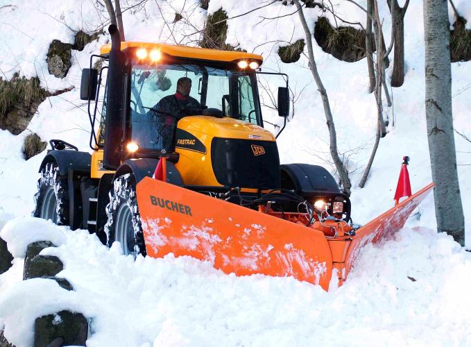
Efficient clearing operations
since 1950
The story of Giletta
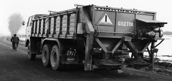
Founded in 1950, Giletta started its operations as a distributor of agricultural machinery. In the years immediately following, the company started as a production company of hay elevators, fertiliser spreaders, and manure spreaders. In 1966, according to a request of a private contractor that carrying out snow clearing operations on the provincial road, Giletta designed a sand and salt spreader. The spreader had a double feed chain, which was the technology used in the production of agricultural machines and had a capacity of 11 cubic metres, suitable for a 6×4 truck. At that time, the largest spreader in Europe was 6 cubic metres, and therefore the new machine represented a great novelty on the market for which the first highways, in order to reduce the number of vehicles, started to buy the new spreader. Thus began the first diversification, from a manufacturer of agricultural machinery to a manufacturer of winter maintenance equipment.
Defined by innovation
Working closely with the customers, attention to details and quality has defined Giletta as one of the most innovative manufacturers in the industry. In 1976, with the introduction of the electronic control of the amount of salt spread based on the speed of the vehicle, Giletta enabled customers to control the amount of material spread. In 1978, the 15 cubic meters spreader was launched and already in 1980, Giletta introduced the first chloride spreader with the pre-wetting system, representing a revolution in winter maintenance due to the significantly lowered risk of accidents.
In 1989, the first fully modular spreader was patented and further steps were taken for digital control of spreading operations with the Ecosat microprocessor. The fully automated satellite control of chloride spreading operations dates back to 1998. In 1999, at the request of the largest Italian motorway company managing in real-time a significant amount of snow-clearing vehicles on the Apennine mountain motorway, the first digital system for tracking and remote control of winter operations was developed.
A Bucher company
In 2002, Giletta joined Bucher Municipal group and made its entry into high-potential markets. In order to complete the range of products and to offer the various markets a full set-up of the vehicles for winter roads, SnowTec, a French manufacturer of innovative snow ploughs, was acquired in 2003. In the acquisition, Bucher Municipal also took over Arvel, the Giletta-owned distributor founded in 1997 responsible for sales and service of winter maintenance equipment in France.
In 2005, the new Bucher UniQa spreader was introduced and the modularisation of production was fully implemented with robotic welding, double-layer powder coating, epoxy with high zinc content, and polyester as well as assembly lines for all products. Furthermore, in 2009, the company invested in Saet, a company specialised in the design and production of electronic controls and related wiring, in order to increase the know-how in all electronic devices for the further strengthening of intelligent products.
Multiple brands and multiple applications
The growth of the Bucher Municipal winter maintenance portfolio continues with the acquisition of the Spanish distributor Maquiafalt in 2011, and in 2012 with the acquisition of Assaloni.com, a historic manufacturer of snow clearing equipment, famous all over the world above all for the patented telescopic snow ploughs. In 2014, the Kaluga production facility in Russia was opened, built for the production of all the equipment destined for this important market, some of which were specifically designed for extreme working conditions in the region.
Ошибки частотных преобразователей: примеры и коды ошибок
Частотные преобразователи — это электронные или электротехнические устройства, предназначенные для изменения и регулировки частоты электрического напряжения. Сфера их использования очень широка: насосные станции, системы тепло- и водоснабжения, линии производства, конвейеры, лифты, центрифуги, мельницы, металлургические агрегаты, буровое оборудование и т. д.
Использование частотных преобразователей на промышленных объектах дает следующие преимущества:
- Возможность отказаться от регулирующего оборудования: дросселей, вариаторов, редукторов и др. Это существенно упрощает работу механической системы, снижает расходы на эксплуатацию и повышает ее надежность.
- Плавный разгон управляемого двигателя, защищающий его от механических ударов и пусковых токов, что продлевает срок его службы.
- Частотные преобразователи в паре с асинхронными двигателями можно использовать в качестве альтернативы для приводов постоянного тока.
- Максимально рациональное регулирование скорости контролируемых двигателей и связанных с этим технологических процедур.
- Экономия электроэнергии, благодаря устранению ее неоправданных трат.
Но, несмотря на свою надежность и эффективность, частотные преобразователи, как и любые электронные приборы, подвержены износу. Инженерная компания 555 специализируется на ремонте промышленной электроники, и в частности — на устранении ошибок частотных преобразователей. Наши специалисты готовы отремонтировать вышедшее из строя оборудование в кратчайшие сроки.
Основные виды и причины неисправностей
Опознать неисправности частотников позволяют коды ошибок, высвечивающиеся на мониторе устройства. Каждая такая комбинация символов указывает на совершенно конкретную проблему, и это помогает специалистам выработать правильную стратегию ремонта. Для начала рассмотрим типовые виды ошибок частотных преобразователей:
- Over Current или OC. Данный сигнал на мониторе устройства свидетельствует о его перегрузке. Если подобная проблема возникла при тестовом запуске, необходимо проверить соответствие токов регулятора и электрической машины, а также исправность электроцепей управляемого двигателя. Следует учесть, что некоторые модели частотников высвечивают ошибку Over Current при торможении, работе и запуске электродвигателя.
- Over Heat или ОН. Это сообщение указывает на превышение номинально допустимой температуры частотного преобразователя. Проще говоря — на его перегрев. Устранить проблему можно посредством чистки внутреннего вентилятора или установки дополнительной вентиляционной системы в бокс, где располагается преобразователь. В качестве профилактики следует размещать частотник в месте, гарантирующем эффективный отвод тепла.
- Over Load или OL. Такая ошибка преобразователя может быть вызвана двумя обстоятельствами: превышением на валу момента силы или перегревом управляемого двигателя. Чтобы устранить проблему, необходимо выполнить корректную настройку тепловой защиты. Для этого во время программирования устройства нужно задать требуемую величину тока и время срабатывания защитной функции.
- Low Voltage или LV. Ошибка высвечивается при снижении напряжения питания или обрыве фаз (одной или двух). Существует два варианта решения этой проблемы: «насильственная» остановка двигателя или настройка его работы в однофазном режиме.
- Over Voltage или OV. Такую надпись можно увидеть на мониторе при замедлении вращения двигателя. Для устранения неисправности необходимо воспользоваться одним из трех способов: переводом устройства в режим генератора, активацией тормозного резистора или перенастройкой системы защиты от повышенного напряжения.
Среди других типовых неисправностей преобразователя следует выделить вращение двигателя в неправильном направлении, невозможность его запуска, проблемы с торможением и разгоном и т. д. Каждое повреждение имеет под собой конкретные причины. Например, если двигатель разгоняется очень медленно, скорее всего, дело в срабатывании функции токоограничения в момент разгона.
В число наиболее распространенных причин неисправностей входят:
- Заводской брак. Как правило, фабричные дефекты дают о себе знать в течение гарантийного срока. Поэтому для их устранения следует обращаться к поставщику или в брендовый сервисный центр.
- Ошибки при монтаже. Чаще всего причиной неисправностей становится некорректная сборка схемы привода или установка частотника в неподходящем месте.
- Нарушение норм эксплуатации. Регламент технического обслуживания изложен в инструкции, прилагаемой к устройству. Игнорирование регламента может привести к выходу из строя полупроводниковых элементов, перегреванию частотного регулятора и другим неисправностям.
- Несоответствие частотного преобразователя условиям его эксплуатации. Основные критерии выбора частотника — электрические характеристики двигателя, исполнение, набор функций и т. д. Несоответствие параметров условиям его эксплуатации приводит к некорректной работе устройства, выходу из строя и многочисленным поломкам.
Теперь поговорим об ошибках преобразователя частоты более подробно и предметно. В качестве примера рассмотрим привод известного китайского бренда INVT ELECTRIC CO, серии GDXXX. Предлагаем вашему вниманию таблицу, в которой представлены коды ошибок устройства, их расшифровка, вероятные причины неисправностей, а также способы их устранения.
| Код ошибки | Расшифровка | Вероятные причины | Способы устранения |
| OUt1, 2, 3 | Ошибка фазы. | Отсутствие заземления или контакта при подсоединении кабеля; слишком маленькое время разгона. | Увеличение времени разгона; замена модуля IGBT; устранение неисправностей внешнего оборудования; переподключение кабеля. |
| OC1, 2, 3 | Токовая перегрузка при разгоне, торможении или постоянной скорости. | Чрезмерное время торможения или разгона; слишком высокое напряжение в сети; недостаточная мощность привода; потеря фазы или короткое замыкание «на землю»; воздействие внешнего фактора. |
Сокращение времени разгона; оптимизация питающего напряжения; приобретение привода с более высокой мощностью; проверка конфигурации выхода; устранение внешних помех. |
| OV1, 2, 3 | Сверхнапряжение при разгоне, торможении или постоянной скорости. | Напряжение на входе не соответствует параметрам привода; чрезмерная энергия торможения. |
Проверка входного напряжения; оптимизация времени торможения/разгона. |
| UV | Слишком низкое напряжение шины. | Пониженное напряжение питания. | Проверка и оптимизация входного напряжения. |
| OL1 | Перегрузка электродвигателя. | Слишком низкое питающее напряжение; неверно заданные параметры тока; чрезмерная нагрузка на электродвигатель. |
Проверка входного напряжения; настройка правильных параметров тока в двигателе; оптимизация нагрузки. |
| OL2 | Перегрузка преобразователя частоты. | Чрезмерно быстрый разгон; остановка двигателя; заниженное питающее напряжение; сверхнагрузка; длительная работа двигателя на низкой скорости. |
Увеличение времени разгона; снижение нагрузки на двигатель; проверка мощности двигателя и входного напряжения; приобретение привода с более высокой мощностью; замена двигателя. |
| OL3 | Перегрузка по электричеству. | Сигнализация перегрузки в соответствии с заданными параметрами. | Проверка нагрузки и точки перегрузки. |
| SPI | Потеря фаз входа. | Потеря колебания или фазы напряжения трех входных фаз. | Проверка и оптимизация входного напряжения и/или правильности монтажа. |
| SPO | Потеря фаз выхода. | Асимметричная нагрузка. | Проверка выхода, двигателя и кабеля. |
| OH1 | Перегревание выпрямителя. | Неисправность вентилятора или засорение вентиляционного канала; слишком высокая температура воздуха в помещении; чрезмерно затянутый запуск устройства. |
Замена вентилятора и проверка воздуховода; снижение температуры окружающей среды; проверка и восстановление воздухообмена; оптимизация мощности нагрузки; замена модуля IGBT; ремонт платы управления. |
| EF | Неисправность внешних элементов. | Повреждение клеммы SIn и/или других внешних клемм. | Замена пришедших в негодность клемм. |
| CE | Проблемы со связью. | Некорректная скорость в бодах; повреждение кабеля связи; неверно заданный адрес сообщения; серьезные помехи в кабеле. |
Оптимизация скорости в бодах; проверка кабеля связи; настройка правильного адреса сообщения; замена кабеля или оптимизация защиты от помех. |
| ItE | Проблемы с обнаружением тока. | Некорректное подключение платы управления; отсутствие вспомогательного напряжения; выход из строя индикаторов тока. |
Проверка разъема, датчиков и платы управления. |
| tE | Ошибка автоматической настройки. | Несоответствие мощностей двигателя и частотного преобразователя; неверно заданные параметры электродвигателя; серьезная разница между стандартными параметрами и параметрами автоматической настройки; выход времени на автонастройку. |
Установка параметров, указанных на шильдике двигателя; снижение нагрузки на двигатель; проверка параметров двигателя и его соединения; установка верхнего предела частоты на уровень «выше 2/3 номинальной частоты». |
| bCE | Неисправность тормозного модуля. | Разрыв тормозных коммуникаций или некорректная работа тормозной цепи; недостаток производительности внешнего тормозного резистора. |
Проверка тормозного модуля и замена тормозных кабелей; принудительное повышение мощности тормозного резистора. |
| ETH1, 2 | Короткое замыкание | Замыкание выхода преобразователя частоты «на землю»; неисправность в цепи определения тока. |
Проверка подключения двигателя и индикаторов тока; замена платы управления. |
| dEu | Отклонение скоростного режима. | Избыточная нагрузка. | Оптимизация нагрузки и увеличение времени обнаружения; проверка и при необходимости корректировка параметров управления. |
| STo | Несогласованность параметров. | Отсутствие параметров управления для синхронных электродвигателей; некорректно заданные параметры автоматической настройки; отсутствие подключения частотника к двигателю. |
Корректировка нагрузки на двигатель; установка корректных параметров управления; увеличение времени определения несогласованности. |
| PCE | Обрыв связи с блоком управления. | Повреждение проводов, обеспечивающих подключение к блоку управления; помехи в проводах, связанные с внешним фактором; некорректное функционирование цепи в основной плате и/или в клавиатуре. |
Замена проводов блока управления; проверка внешней среды и устранение источника помех; выполнение комплексного сервисного обслуживания устройства. |
| END | Сброс времени до заводских настроек. | Фактическое время функционирования преобразователя не соответствует внутреннему параметру продолжительности работы. | Корректировка настроек времени. |
| DNE | Проблема с загрузкой параметров. | Повреждение проводов, подключаемых к блоку управления; помехи в проводах; ошибка в базе данных панели управления. |
Замена проводов блока управления; сервисное обслуживание частотного преобразователя; повторная загрузка данных в панель управления. |
Преимущества ремонта в инженерной компании 555
- Огромный опыт в ремонте частотных преобразователей разных моделей и марок.
- Команда профессиональных специалистов.
- Экономия до 70 % средств по сравнению с приобретением нового оборудования.
- Оперативное выполнение работ (максимальный срок ремонта — 15 дней).
- Бесплатная консультация и предварительный осмотр для определения ремонтопригодности привода.
- Доступные цены и оплата только по результату работы.
- Гарантия на отремонтированное оборудование — 12 месяцев.
Обращайтесь к нам из любой точки России, через сайт или по телефону. Промышленная электроника — это очень сложное и специфичное оборудование, которое следует доверять только профессионалам.
Мы ремонтируем:
![]()

Компания ООО «Барс-Гидравлик Групп» на протяжении нескольких лет успешно сотрудничает с ООО «Инженерная компания 555» в вопросах ремонта сложного промышленного оборудования. За время работы наш партнер зарекомендовал себя с самой лучшей стороны. Заказы выполняются в кротчайшие сроки при соблюдении высокого качества работ. Организация приема и выдачи заказов четкая. Гарантийные обязательства выполняются в полном объеме.
Выражаем благодарность Вашим специалистам за профессионализм и оперативное решение поставленных задач.
Особенно хочется отметить высокую клиентоориентированность персонала Вашей компании, готовность помочь в самых сложных ситуациях.
Мы высоко ценим сложившиеся между нашими компаниями открытые и доверительные партнерские отношения и искренне желаем «Инженерной компании «555» долгих лет успеха и процветания.
Читать весь
отзыв

ООО «Инженерная компания «555» оказывала нашей компании услуги по ремонту электродвигателей и проявила пунктуальность, аккуратность и ответственность в работе.
Результат выполненных работ говорит о качественном оборудовании и высококвалифицированных кадрах.
Сотрудники компании готовы выполнить новые для себя виды работ и оказать консультационные услуги, что характеризует их как профессионалов своего дела.
Рекомендуем ООО «ИК «555» как ответственного и надежного поставщика услуг.
Читать весь
отзыв

Сообщаем, что наша организация сотрудничает с ООО «Инженерная компания «555» с мая 2016 года по настоящее время.
За этот период мы обращались к услугам компании более 10 раз.
Благодаря серьезному и квалифицированному подходу сотрудников ООО «Инженерная компания «555» ремонтные работы произведены качественно с учетом сроков, и обеспечены гарантийным сопровождением.
Планируем в дальнейшем работать с ООО «Инженерная компания «555»
Читать весь
отзыв

Уважаемый Дмитрий Васильевич!
ОАО «Октябрьский электровагоноремонтный завод» успешно работает с ООО «Инженерная компания «555» несколько лет, очень довольны данным сотрудничеством. В работе компании наибольшую ценность для нас представляет готовность работать на условиях, удобных Заказчику, качественный ремонт оборудования в заявленные сроки и самое главное, финансовая защищенность Заказчика. В инженерной компании работают внимательные, доброжелательные сотрудники, готовые в любой момент решить проблему Заказчика. Мы рады, что выбрали ООО «Инженерная компания «555» в качестве партнера. Гарантируем дальнейшее сотрудничество!
Читать весь
отзыв

ЗАО «Охтинское» выражает глубокую признательность и истинную благодарность ООО Инженерной компании «555» за качественную работу компании по ремонту сложного оборудования промышленной электроники, оперативность и технически грамотное отношение к работе в течении всего периода сотрудничества.
Мы надеемся на дальнейшее успешное развитие деловых отношений в сфере ремонта промышленной электроники.
Читать весь
отзыв
Преимущества сотрудничества с нами

Оплата только за результат — работающий блок

Гарантия на работоспособность блока целиком 12 месяцев

Срок ремонта от 5 до 15 дней

Бесплатный предварительный осмотр на предмет ремонтопригодности

Не вносим конструктивных изменений

Ремонт на компонентном уровне
Наша лаборатория расположена в Санкт-Петербурге, но обратиться за помощью вы можете из любой точки России.
Закажите обратный звонок или наберите в рабочее время многоканальный телефон
– +7 (800) 555-89-01 (звонок по России бесплатный).
Расскажите о своей проблеме и получите инструкцию к дальнейшим действиям.