Ошибка печатающей головки
- Ответить с цитатой
Ошибка печатающей головки
Здравствуйте,
Эко сольвентный принтер, одна головка(Epson), меняли шлейфы(их 2) от головки к плате коретки, когда запустили печать, один шлейф вылетел, и станок стал давать ошибку
— fta 37 epson head error occurs,
Ставили новые шлейфы, включали выключали, переставляли на порты ко второй головке, та же ошибка.
Что делать?
Спасибо большое.
- Yldyrymlar
- Сообщения: 6
- Зарегистрирован: 29 мар 2013, 15:38
- Город: Ashgabat
- Ответить с цитатой
Re: Ошибка печатающей головки
![]() Олег Королев » 29 мар 2013, 16:03
Олег Королев » 29 мар 2013, 16:03
Вы девушка?
Я не знаю таких принтеров, но по симтомам не трудно догадаться, что произошло короткое замыкание, и возможно сгорел предохранитель на плате. Вам надо быстро найти знакомого, который умеет паять и ремонтирует компьютеры, к примеру, пусть он прозвонит» плату. Там работы на 5 мин.
- Олег Королев
- Сообщения: 276
- Зарегистрирован: 26 фев 2013, 11:16
- Город: Находка
- Ответить с цитатой
Re: Ошибка печатающей головки
![]() Yldyrymlar » 29 мар 2013, 16:12
Yldyrymlar » 29 мар 2013, 16:12
Да, девушка.
Значит, все не так страшно?
Принтер эко сольвентный Yinghe YH3200R, китайцы говорят надо менять плату корретки, отослать им на ремонт, а это долго, и, наверно, дорого.
Там, вроде нет предохранителя. И на микросхемах платы стерты надписи.
- Yldyrymlar
- Сообщения: 6
- Зарегистрирован: 29 мар 2013, 15:38
- Город: Ashgabat
- Ответить с цитатой
Re: Ошибка печатающей головки
![]() Олег Королев » 29 мар 2013, 16:16
Олег Королев » 29 мар 2013, 16:16
Там роль предохранителя выполняют резисторы. Там не сложно. Работы на 5 мин. Наидите спеца, что умеет ремонтировать телефоны, к примеру. Тоже разберется. Пусть прозвонит все резисторы.
- Олег Королев
- Сообщения: 276
- Зарегистрирован: 26 фев 2013, 11:16
- Город: Находка
- Ответить с цитатой
Re: Ошибка печатающей головки
![]() Олег Королев » 29 мар 2013, 16:21
Олег Королев » 29 мар 2013, 16:21
Спецы по принтерам, Александры, помогите девушке. Я не знаю таких принтеров, тем более китайских, но девушка спросил меня помощи через личное сообщения. Пытаюсь помочь. Я не сервисный инженер. Китайские принтеры не знаю.
-
Олег Королев
- Сообщения: 276
- Зарегистрирован: 26 фев 2013, 11:16
- Город: Находка
- Ответить с цитатой
Re: Ошибка печатающей головки
![]() Yldyrymlar » 29 мар 2013, 16:27
Yldyrymlar » 29 мар 2013, 16:27
Спасибо, большое, парень который станок настраивал, сказал что зайдет вечером, это где-то через пол часа, час.
А что может выполнить функцию предохранителя кроме резистора?
- Yldyrymlar
- Сообщения: 6
- Зарегистрирован: 29 мар 2013, 15:38
- Город: Ashgabat
- Ответить с цитатой
Re: Ошибка печатающей головки
![]() Yldyrymlar » 29 мар 2013, 16:40
Yldyrymlar » 29 мар 2013, 16:40
Знаю где находится ваш город, правда сколько времени у вас не знала.
У нас время близится к 19 00.
Спасибо большое, за то что так оперативно откликнулись, надеюсь плату в китай отправлять не надо будет.
Еще раз спасибо.
Как дело решится отпишусь.
- Yldyrymlar
- Сообщения: 6
- Зарегистрирован: 29 мар 2013, 15:38
- Город: Ashgabat
- Ответить с цитатой
Re: Ошибка печатающей головки
![]() Yldyrymlar » 30 мар 2013, 16:16
Yldyrymlar » 30 мар 2013, 16:16
Заменили сгоревшую плату, ту починить можно будет отправив в Китай на ремонт, так как, с микросхем все стерто.
- Yldyrymlar
- Сообщения: 6
- Зарегистрирован: 29 мар 2013, 15:38
- Город: Ashgabat
Вернуться в Прочие сольвентные принтеры
Кто сейчас на конференции
Сейчас этот форум просматривают: нет зарегистрированных пользователей и гости: 0
- Список форумов
- Наша команда • Удалить cookies конференции • Часовой пояс: UTC + 3 часа
Просмотр полной версии : востановление поврежденных голов +/ damage head unit repair
Страницы :
[1]
2
3
4
sergeynik
26.11.2013, 00:15
для начала нада понять структуру памяти
IPL лежит всегда с адреса 0 он и получает управление, если ножка RxD терминального порта замкнута на корпус то будет запуск диалогового меню, иначе исчет в памяти заголовоки ifs-root и fpga если заголовка fpga не находит запускает емергенси режим ifs em и fpga em.
карта 128мб одного из вариантов блоков
0x00000000 ipl 63264 из 262144 (256kb)
0x00040000 fpga 746472 из 786432 (768 кб)
0x00100000 fpga em 746472 из 786432 (768 кб)
0x001C0000 ifs em 4666284 из 6029312 (5888кб 5мб)
0x00780000 ifs-root 36866456 из 50855936 (49664кб 48мб)
0x03800000 efs ext 23068672 из 58720256 (57344кб 56мб)
0x04E00000 efs sys 20971520 из 20971520 (20480кб 20mb)
0x06200000 efs per 30408704 из 31457280 (29696kb 29mb)
0x07f00000 bios
0x08000000 end 128 mb
в диалоговом режиме можно выбрать что грузить в этот раз
если эмергенси система уцелела то грузимся в нее и пользуем команду
flashit -a 40000 -e 1000
НЕПЕРЕПУТАЙТЕ КОЛИЧЕСТВО НУЛЕЙ !!! адресс 4000 например убьет голову!!!
это сотрет заголовок FPGA и при след загрузке IPL не найдя его запустит аварийное восстановление системы. ниже хелп на flashit.
flashit — Generic flash tool (uses devf-*, fs-etfs-*) for hardware access)
flashit [-v[vvv]] [-p device] [-a address] -e size
flashit [-v[vvv]] [-p device] [-a address] -f file [-x] [-i fid] [-s seq]
Options:
-a address start address in hex the file should be flashed to
-d if set, all necessary sectors will be erased
-e size erase size number of bytes
-f file name of the file to be flashed
-l step [obsolete/not supported: stepwidth of progress procentage]
-p device path to raw flash device (default: /dev/fs0; NAND is /dev/etfs1)
-x do not verify data written
-v increase verbosity
Options specific to NAND flash:
-i fid file ID (default: 0)
-s seq sequence number (default: 0)
Example:
flashit -a 80000 -d -f w221-b1_2.ifs OR
flashit -a 0x80000 -d -f w221-b1_2.ifs
This call flashes the file w221-b1_2.ifs starting at address 0x80000.
All sectors/blocks the file covers are erased before.
flashit -p /dev/etfs1 -a 80000 -f rneg_6426.ifs OR
flashit -p /dev/etfs1 -a 0x80000 -f rneg_6426.ifs
This call flashes the file rneg_6426.ifs into NAND flash starting
at address 0x80000. All blocks the file covers are erased before.
flashit -a 80000 -e 20000 OR
flashit -a 0x80000 -e 0x20000
Erases the flash from address 0x80000 until 0xA0000.
All sectors/blocks covered by the range given are erased completely.
ImDarius
20.01.2014, 14:34
если ножка RxD терминального порта замкнута на корпус то будет запуск диалогового меню.
речъ идeт об том самом Rx в углу платы ?
5 контакты от угла платы, с одной стороны платы тх с другой рх
|
|
|…_ разьем_
|_| |______| |____________
sergeynik
20.01.2014, 18:28
да об нем
sergeynik
21.01.2014, 18:06
DUK а че не выкладываешь свой документ по востановлению
ImDarius
21.01.2014, 18:51
и так, имею два мертвых мми, один совсем дохлы, никак не отвечает на терминал, а второй вроде показывает признак жизни и успешно присоединил,
но — не могу поднять,пишет чо такой команды нету flashit , может чо не так делаю ? ето голова из Toureg, вроде rns850, но когда то всунул не тот диск ( от ауди а4) перешился но на дисплее нечего не показывал,по диагнозе отвечал, поставил в ауди а4 LCD показывал, вроде работал, не стал долго возится,поставил в угол-подумал что кому понадобится от ауди и поставлю, но один ден камуто понадобился,поставил, но както криво работал, вставил ичо раз диск и сдох совсем, восстановить как рнс850 никак не мог, через емергенси прошивал но не помогло, а родной диск не перенимал.
22538225392254022541
DUK а че не выкладываешь свой документ по востановлению
Да просто пока не все нюансы напечатал + немного занят. Но выложу.
ImDarius (http://turbo-quattro.com/member.php?6686-ImDarius), когда «приглашение» вот такое => — это IPL — как бы не QNX. У IPL свои команды (ты их выводил по help)
М.б. Сергей что то подскажет, но, КМК, лучше просто грузи голову без запуска IPL и выложи весь лог того, что она выдает на терминал.
Но вроде по картинке №4 у тебя ждет установки диска или карточки с прошивкой
sergeynik
21.01.2014, 20:45
boot 1c0000
когда туда загрузится уже стирай
но прежде покажи че там ваще есть командой scan
ImDarius
21.01.2014, 21:41
IPL: Audi 3G 9308 (SH7785) / QNX 6.3.0 [PL_qnx_ipl-3g_9308-sh7785_08253A, built 2008/06/18_15-16-25_UTC]
CPU: SH7785 (>= 5th cut, clk mode 20. 4xDDR), 792MHz
RAM: 512 MB (probed, DBCONF=e30002)
FLASH: Spansion S29GL512N (32bit): 512 sectors x 256K
FPGA: PL_MMI3G_PLUS_FPGA_9411_D1_09422A
(0ms)
*** emergency FPGA loaded!
Entering CLI, type ‘?’ or ‘help’ for help
=> boot 1c0000
starting image @801c0000 …
Startup: PL_qnx_startup-sh7785_08362A, built 2008/09/02_07-53-12_UTC
RAM : 256 MB @0x08000000
FLASH: 128 MB @0x00000000
System page at phys:0800a000 user:0800a000 kern:8800a000
Starting next program at v88046840
——————————————————
Welcome to QNX 6.3.2 (RL_qnx_os_632_PSP3_08124A) MMI3G Audi EMERGENCY SETUP 9308 D1 09431A
starting pci driver
*** init FPGA registers ***
Unable to access «/dev/sysregs» (2)
starting dev-ipc for IOC
initialize IPC Driver
Can’t start driver ‘/dev/ipc/onoff’starting network driver
starting atapi driver — setup device /dev/cam0
xpt_configure: No eide interfaces found
Unable to access «/dev/cam0» (2)
starting devc-pty
starting flash driver
starting SDCard driver
Unable to access «/dev/io-net/en5» (2)
starting with no network driver
================================================== =========
Emergency IFS is started. Emergency app tries to restore
the application.
================================================== =========
69644 running /usr/bin/devg-NVTIRM
DMA is Disabled
dma disabled, interrupt thread priority = 100
69646 running /sbin/io-media-nvidia
69647 running /usr/sbin/io-display
69648 running /usr/apps/MMI3GEmergencyApp
================================================== =========
Emergency shell started, fix your system and restart again
================================================== =========
discplayer_init: IN
nvidia_render_manager_init: IN
INvmRenderManager::GetNvmRenderManager (&pRenderManager);
er = pRenderManager->Init(oConfig);
# scanhjuhyyugyugygFpga header is not 0x4744482e (0xffffffff)!
App FPGA valid 0
Emergency FPGA valid 1
COnOffIPC.cpp:41: ASSERTION failed
Disabling IOC watchdog
COnOffIPC.cpp:76: ASSERTION failed
EmergencyApp-MMI3G: version 22.30.2098, date of build 14.10.2009
pRenderManager->Open()
nvidia_render_manager_init: OUT
discplayer_init: OUT
discplayer_init
discplayer_init: IN
nvidia_render_manager_init: IN
nvidia_render_manager_init: OUT
discplayer_init: OUT
dvdtrackplayer_init
discplayer_init: IN
nvidia_render_manager_init: IN
nvidia_render_manager_init: OUT
discplayer_init: OUT
dvdnavigator_init
created navigator control point with 8249288
mixer_init: IN
mixer_init: OUT
NvTRACELEVEL set to 3 (Level Info)
nVAudio_init: IN
nvidia_render_manager_init();
nvidia_render_manager_init: IN
nvidia_render_manager_init: OUT
nVAudio_init: OUT
installing audio decoders
installing video decoders
nVAudio_init: IN
nvidia_render_manager_init();
nvidia_render_manager_init: IN
nvidia_render_manager_init: OUT
nVAudio_init: OUT
OnIpcGetCaptureUnitSourceCount
Number of displays: 6
Number of layers: 9
ImDarius
21.01.2014, 21:41
IPL: Audi 3G 9308 (SH7785) / QNX 6.3.0 [PL_qnx_ipl-3g_9308-sh7785_08253A, built 2008/06/18_15-16-25_UTC]
CPU: SH7785 (>= 5th cut, clk mode 20. 4xDDR), 792MHz
RAM: 512 MB (probed, DBCONF=e30002)
FLASH: Spansion S29GL512N (32bit): 512 sectors x 256K
FPGA: PL_MMI3G_PLUS_FPGA_9411_D1_09422A
(0ms)
*** emergency FPGA loaded!
Entering CLI, type ‘?’ or ‘help’ for help
=> scan
** @0x80100000: FPGA
total size: 746480 [0x0b63f0]
data: 746212 [0x0b62e4]
.FDR = PL_MMI3G_PLUS_FPGA_9411_D1_09422A
.FDU = Userinfos zu FPGA 9411_D1_4010_14lw
** @0x801c0000: IFS [vers.1, UCL, old EMERGENCY]
total size: 4666284 [0x4733ac]
— header: 256
— startup: 53512
— imagefs: 11565604
RAM: 11619116 [0xb14b2c]
** @0x80780000: IFS [vers.1, LZO, old APPLICATION]
total size:36867924 [0x2328f54]
— header: 256
— startup: 53512
— imagefs: 85872380
RAM: 85925892 [0x51f2004]
=== DATA CHECKSUM ERROR! ===
** @0x87f00000: BIOS packet
total size: 786432 [0x0c0000]
BIOS pattern: FFFFFF7F.FFFFFFFF
App. pattern: FFFFFF7F.FFFFFFFF
=> IPL: Audi 3G 9308 (SH7785) / QNX 6.3.0 [PL_qnx_ipl-3g_9308-sh7785_08253A, built 2008/06/18_15-16-25_UTC]
Unknown command ‘IPL:’ — try ‘help’
=> CPU: SH7785 (>= 5th cut, clk mode 20. 4xDDR), 792MHz
Unknown command ‘CPU:’ — try ‘help’
=> RAM: 512 MB (probed, DBCONF=e30002)
Unknown command ‘RAM:’ — try ‘help’
=> FLASH: Spansion S29GL512N (32bit): 512 sectors x 256K
Unknown command ‘FLASH:’ — try ‘help’
=> FPGA: PL_MMI3G_PLUS_FPGA_9411_D1_09422A
Unknown command ‘FPGA:’ — try ‘help’
=> (0ms)
Unknown command ‘(0ms)’ — try ‘help’
=> *** emergency FPGA loaded!
Unknown command ‘***’ — try ‘help’
=>
=> Entering CLI, type ‘?’ or ‘help’ for help
Unknown command ‘Entering’ — try ‘help’
=>
=> => scan
Unknown command ‘=>’ — try ‘help’
=> ** @0x80100000: FPGA
Unknown command ‘**’ — try ‘help’
=>
=> total size: 746480 [0x0b63f0]
Unknown command ‘total’ — try ‘help’
=> data: 746212 [0x0b62e4]
Unknown command ‘data:’ — try ‘help’
=>
=> .FDR = PL_MMI3G_PLUS_FPGA_9411_D1_09422A
Unknown command ‘.FDR’ — try ‘help’
=>
=> .FDU = Userinfos zu FPGA 9411_D1_4010_14lw
Unknown command ‘.FDU’ — try ‘help’
=>
=> ** @0x801c0000: IFS [vers.1, UCL, old EMERGENCY]
Unknown command ‘**’ — try ‘help’
=>
=> total size: 4666284 [0x4733ac]
Unknown command ‘total’ — try ‘help’
=> — header: 256
Unknown command ‘-‘ — try ‘help’
=> — startup: 53512
Unknown command ‘-‘ — try ‘help’
=> — imagefs: 11565604
Unknown command ‘-‘ — try ‘help’
=>
=> RAM: 11619116 [0xb14b2c]
Unknown command ‘RAM:’ — try ‘help’
=>
=> ** @0x80780000: IFS [vers.1, LZO, old APPLICATION]
Unknown command ‘**’ — try ‘help’
=>
=> total size:36867924 [0x2328f54]
Unknown command ‘total’ — try ‘help’
=> — header: 256
Unknown command ‘-‘ — try ‘help’
=> — startup: 53512
Unknown command ‘-‘ — try ‘help’
=> — imagefs: 85872380
Unknown command ‘-‘ — try ‘help’
=>
=> RAM: 85925892 [0x51f2004]
Unknown command ‘RAM:’ — try ‘help’
=>
=> === DATA CHECKSUM ERROR! ===
Unknown command ‘===’ — try ‘help’
=>
=> ** @0x87f00000: BIOS packet
Unknown command ‘**’ — try ‘help’
=>
=> total size: 786432 [0x0c0000]
Unknown command ‘total’ — try ‘help’
=>
=> BIOS pattern: FFFFFF7F.FFFFFFFF
Unknown command ‘BIOS’ — try ‘help’
=> App. pattern: FFFFFF7F.FFFFFFFF
Unknown command ‘App.’ — try ‘help’
=>
ImDarius
21.01.2014, 21:43
вроде сторл ?
IPL: Audi 3G 9308 (SH7785) / QNX 6.3.0 [PL_qnx_ipl-3g_9308-sh7785_08253A, built 2008/06/18_15-16-25_UTC]
CPU: SH7785 (>= 5th cut, clk mode 20. 4xDDR), 792MHz
RAM: 512 MB (probed, DBCONF=e30002)
FLASH: Spansion S29GL512N (32bit): 512 sectors x 256K
FPGA: PL_MMI3G_PLUS_FPGA_9411_D1_09422A
(0ms)
*** emergency FPGA loaded!
Entering CLI, type ‘?’ or ‘help’ for help
=> scan
** @0x80100000: FPGA
total size: 746480 [0x0b63f0]
data: 746212 [0x0b62e4]
.FDR = PL_MMI3G_PLUS_FPGA_9411_D1_09422A
.FDU = Userinfos zu FPGA 9411_D1_4010_14lw
** @0x801c0000: IFS [vers.1, UCL, old EMERGENCY]
total size: 4666284 [0x4733ac]
— header: 256
— startup: 53512
— imagefs: 11565604
RAM: 11619116 [0xb14b2c]
** @0x80780000: IFS [vers.1, LZO, old APPLICATION]
total size:36867924 [0x2328f54]
— header: 256
— startup: 53512
— imagefs: 85872380
RAM: 85925892 [0x51f2004]
=== DATA CHECKSUM ERROR! ===
** @0x87f00000: BIOS packet
total size: 786432 [0x0c0000]
BIOS pattern: FFFFFF7F.FFFFFFFF
App. pattern: FFFFFF7F.FFFFFFFF
=> IPL: Audi 3G 9308 (SH7785) / QNX 6.3.0 [PL_qnx_ipl-3g_9308-sh7785_08253A, built 2008/06/18_15-16-25_UTC]
Unknown command ‘IPL:’ — try ‘help’
=> CPU: SH7785 (>= 5th cut, clk mode 20. 4xDDR), 792MHz
Unknown command ‘CPU:’ — try ‘help’
=> RAM: 512 MB (probed, DBCONF=e30002)
Unknown command ‘RAM:’ — try ‘help’
=> FLASH: Spansion S29GL512N (32bit): 512 sectors x 256K
Unknown command ‘FLASH:’ — try ‘help’
=> FPGA: PL_MMI3G_PLUS_FPGA_9411_D1_09422A
Unknown command ‘FPGA:’ — try ‘help’
=> (0ms)
Unknown command ‘(0ms)’ — try ‘help’
=> *** emergency FPGA loaded!
Unknown command ‘***’ — try ‘help’
=>
=> Entering CLI, type ‘?’ or ‘help’ for help
Unknown command ‘Entering’ — try ‘help’
=>
=> => scan
Unknown command ‘=>’ — try ‘help’
=> ** @0x80100000: FPGA
Unknown command ‘**’ — try ‘help’
=>
=> total size: 746480 [0x0b63f0]
Unknown command ‘total’ — try ‘help’
=> data: 746212 [0x0b62e4]
Unknown command ‘data:’ — try ‘help’
=>
=> .FDR = PL_MMI3G_PLUS_FPGA_9411_D1_09422A
Unknown command ‘.FDR’ — try ‘help’
=>
=> .FDU = Userinfos zu FPGA 9411_D1_4010_14lw
Unknown command ‘.FDU’ — try ‘help’
=>
=> ** @0x801c0000: IFS [vers.1, UCL, old EMERGENCY]
Unknown command ‘**’ — try ‘help’
=>
=> total size: 4666284 [0x4733ac]
Unknown command ‘total’ — try ‘help’
=> — header: 256
Unknown command ‘-‘ — try ‘help’
=> — startup: 53512
Unknown command ‘-‘ — try ‘help’
=> — imagefs: 11565604
Unknown command ‘-‘ — try ‘help’
=>
=> RAM: 11619116 [0xb14b2c]
Unknown command ‘RAM:’ — try ‘help’
=>
=> ** @0x80780000: IFS [vers.1, LZO, old APPLICATION]
Unknown command ‘**’ — try ‘help’
=>
=> total size:36867924 [0x2328f54]
Unknown command ‘total’ — try ‘help’
=> — header: 256
Unknown command ‘-‘ — try ‘help’
=> — startup: 53512
Unknown command ‘-‘ — try ‘help’
=> — imagefs: 85872380
Unknown command ‘-‘ — try ‘help’
=>
=> RAM: 85925892 [0x51f2004]
Unknown command ‘RAM:’ — try ‘help’
=>
=> === DATA CHECKSUM ERROR! ===
Unknown command ‘===’ — try ‘help’
=>
=> ** @0x87f00000: BIOS packet
Unknown command ‘**’ — try ‘help’
=>
=> total size: 786432 [0x0c0000]
Unknown command ‘total’ — try ‘help’
=>
=> BIOS pattern: FFFFFF7F.FFFFFFFF
Unknown command ‘BIOS’ — try ‘help’
=> App. pattern: FFFFFF7F.FFFFFFFF
Unknown command ‘App.’ — try ‘help’
=>
=> boot 1c0000
starting image @801c0000 …
Startup: PL_qnx_startup-sh7785_08362A, built 2008/09/02_07-53-12_UTC
RAM : 256 MB @0x08000000
FLASH: 128 MB @0x00000000
System page at phys:0800a000 user:0800a000 kern:8800a000
Starting next program at v88046840
——————————————————
Welcome to QNX 6.3.2 (RL_qnx_os_632_PSP3_08124A) MMI3G Audi EMERGENCY SETUP 9308 D1 09431A
starting pci driver
*** init FPGA registers ***
Unable to access «/dev/sysregs» (2)
starting dev-ipc for IOC
initialize IPC Driver
Can’t start driver ‘/dev/ipc/onoff’starting network driver
starting atapi driver — setup device /dev/cam0
xpt_configure: No eide interfaces found
Unable to access «/dev/cam0» (2)
starting devc-pty
starting flash driver
starting SDCard driver
Unable to access «/dev/io-net/en5» (2)
starting with no network driver
================================================== =========
Emergency IFS is started. Emergency app tries to restore
the application.
================================================== =========
69644 running /usr/bin/devg-NVTIRM
DMA is Disabled
dma disabled, interrupt thread priority = 100
69646 running /sbin/io-media-nvidia
69647 running /usr/sbin/io-display
69648 running /usr/apps/MMI3GEmergencyApp
================================================== =========
Emergency shell started, fix your system and restart again
================================================== =========
discplayer_init: IN
nvidia_render_manager_init: IN
INvmRenderManager::GetNvmRenderManager (&pRenderManager);
er = pRenderManager->Init(oConfig);
# help
No such file or directory
# Fpga header is not 0x4744482e (0xffffffff)!
App FPGA valid 0
Emergency FPGA valid 1
COnOffIPC.cpp:41: ASSERTION failed
Disabling IOC watchdog
COnOffIPC.cpp:76: ASSERTION failed
EmergencyApp-MMI3G: version 22.30.2098, date of build 14.10.2009
pRenderManager->Open()
nvidia_render_manager_init: OUT
discplayer_init: OUT
discplayer_init
discplayer_init: IN
nvidia_render_manager_init: IN
nvidia_render_manager_init: OUT
discplayer_init: OUT
dvdtrackplayer_init
discplayer_init: IN
nvidia_render_manager_init: IN
nvidia_render_manager_init: OUT
discplayer_init: OUT
dvdnavigator_init
created navigator control point with 8249288
mixer_init: IN
mixer_init: OUT
NvTRACELEVEL set to 3 (Level Info)
nVAudio_init: IN
nvidia_render_manager_init();
nvidia_render_manager_init: IN
nvidia_render_manager_init: OUT
nVAudio_init: OUT
installing audio decoders
installing video decoders
nVAudio_init: IN
nvidia_render_manager_init();
nvidia_render_manager_init: IN
nvidia_render_manager_init: OUT
nVAudio_init: OUT
OnIpcGetCaptureUnitSourceCount
Number of displays: 6
Number of layers: 9
help
No such file or directory
# flashit -a 40000 -e 1000
*** erasing …
*** verifying …
#
ImDarius
21.01.2014, 21:46
после ребута
IPL: Audi 3G 9308 (SH7785) / QNX 6.3.0 [PL_qnx_ipl-3g_9308-sh7785_08253A, built 2008/06/18_15-16-25_UTC]
CPU: SH7785 (>= 5th cut, clk mode 20. 4xDDR), 792MHz
RAM: 512 MB (probed, DBCONF=e30002)
FLASH: Spansion S29GL512N (32bit): 512 sectors x 256K
FPGA: PL_MMI3G_PLUS_FPGA_9411_D1_09422A
(0ms)
*** emergency FPGA loaded!
Entering CLI, type ‘?’ or ‘help’ for help
=> scan
** @0x80100000: FPGA
total size: 746480 [0x0b63f0]
data: 746212 [0x0b62e4]
.FDR = PL_MMI3G_PLUS_FPGA_9411_D1_09422A
.FDU = Userinfos zu FPGA 9411_D1_4010_14lw
** @0x801c0000: IFS [vers.1, UCL, old EMERGENCY]
total size: 4666284 [0x4733ac]
— header: 256
— startup: 53512
— imagefs: 11565604
RAM: 11619116 [0xb14b2c]
** @0x80780000: IFS [vers.1, LZO, old APPLICATION]
total size:36867924 [0x2328f54]
— header: 256
— startup: 53512
— imagefs: 85872380
RAM: 85925892 [0x51f2004]
=== DATA CHECKSUM ERROR! ===
** @0x87f00000: BIOS packet
total size: 786432 [0x0c0000]
BIOS pattern: FFFFFF7F.FFFFFFFF
App. pattern: FFFFFF7F.FFFFFFFF
=> IPL: Audi 3G 9308 (SH7785) / QNX 6.3.0 [PL_qnx_ipl-3g_9308-sh7785_08253A, built 2008/06/18_15-16-25_UTC]
Unknown command ‘IPL:’ — try ‘help’
=> CPU: SH7785 (>= 5th cut, clk mode 20. 4xDDR), 792MHz
Unknown command ‘CPU:’ — try ‘help’
=> RAM: 512 MB (probed, DBCONF=e30002)
Unknown command ‘RAM:’ — try ‘help’
=> FLASH: Spansion S29GL512N (32bit): 512 sectors x 256K
Unknown command ‘FLASH:’ — try ‘help’
=> FPGA: PL_MMI3G_PLUS_FPGA_9411_D1_09422A
Unknown command ‘FPGA:’ — try ‘help’
=> (0ms)
Unknown command ‘(0ms)’ — try ‘help’
=> *** emergency FPGA loaded!
Unknown command ‘***’ — try ‘help’
=>
=> Entering CLI, type ‘?’ or ‘help’ for help
Unknown command ‘Entering’ — try ‘help’
=>
=> => scan
Unknown command ‘=>’ — try ‘help’
=> ** @0x80100000: FPGA
Unknown command ‘**’ — try ‘help’
=>
=> total size: 746480 [0x0b63f0]
Unknown command ‘total’ — try ‘help’
=> data: 746212 [0x0b62e4]
Unknown command ‘data:’ — try ‘help’
=>
=> .FDR = PL_MMI3G_PLUS_FPGA_9411_D1_09422A
Unknown command ‘.FDR’ — try ‘help’
=>
=> .FDU = Userinfos zu FPGA 9411_D1_4010_14lw
Unknown command ‘.FDU’ — try ‘help’
=>
=> ** @0x801c0000: IFS [vers.1, UCL, old EMERGENCY]
Unknown command ‘**’ — try ‘help’
=>
=> total size: 4666284 [0x4733ac]
Unknown command ‘total’ — try ‘help’
=> — header: 256
Unknown command ‘-‘ — try ‘help’
=> — startup: 53512
Unknown command ‘-‘ — try ‘help’
=> — imagefs: 11565604
Unknown command ‘-‘ — try ‘help’
=>
=> RAM: 11619116 [0xb14b2c]
Unknown command ‘RAM:’ — try ‘help’
=>
=> ** @0x80780000: IFS [vers.1, LZO, old APPLICATION]
Unknown command ‘**’ — try ‘help’
=>
=> total size:36867924 [0x2328f54]
Unknown command ‘total’ — try ‘help’
=> — header: 256
Unknown command ‘-‘ — try ‘help’
=> — startup: 53512
Unknown command ‘-‘ — try ‘help’
=> — imagefs: 85872380
Unknown command ‘-‘ — try ‘help’
=>
=> RAM: 85925892 [0x51f2004]
Unknown command ‘RAM:’ — try ‘help’
=>
=> === DATA CHECKSUM ERROR! ===
Unknown command ‘===’ — try ‘help’
=>
=> ** @0x87f00000: BIOS packet
Unknown command ‘**’ — try ‘help’
=>
=> total size: 786432 [0x0c0000]
Unknown command ‘total’ — try ‘help’
=>
=> BIOS pattern: FFFFFF7F.FFFFFFFF
Unknown command ‘BIOS’ — try ‘help’
=> App. pattern: FFFFFF7F.FFFFFFFF
Unknown command ‘App.’ — try ‘help’
=>
=> boot 1c0000
starting image @801c0000 …
Startup: PL_qnx_startup-sh7785_08362A, built 2008/09/02_07-53-12_UTC
RAM : 256 MB @0x08000000
FLASH: 128 MB @0x00000000
System page at phys:0800a000 user:0800a000 kern:8800a000
Starting next program at v88046840
——————————————————
Welcome to QNX 6.3.2 (RL_qnx_os_632_PSP3_08124A) MMI3G Audi EMERGENCY SETUP 9308 D1 09431A
starting pci driver
*** init FPGA registers ***
Unable to access «/dev/sysregs» (2)
starting dev-ipc for IOC
initialize IPC Driver
Can’t start driver ‘/dev/ipc/onoff’starting network driver
starting atapi driver — setup device /dev/cam0
xpt_configure: No eide interfaces found
Unable to access «/dev/cam0» (2)
starting devc-pty
starting flash driver
starting SDCard driver
Unable to access «/dev/io-net/en5» (2)
starting with no network driver
================================================== =========
Emergency IFS is started. Emergency app tries to restore
the application.
================================================== =========
69644 running /usr/bin/devg-NVTIRM
DMA is Disabled
dma disabled, interrupt thread priority = 100
69646 running /sbin/io-media-nvidia
69647 running /usr/sbin/io-display
69648 running /usr/apps/MMI3GEmergencyApp
================================================== =========
Emergency shell started, fix your system and restart again
================================================== =========
discplayer_init: IN
nvidia_render_manager_init: IN
INvmRenderManager::GetNvmRenderManager (&pRenderManager);
er = pRenderManager->Init(oConfig);
# help
No such file or directory
# Fpga header is not 0x4744482e (0xffffffff)!
App FPGA valid 0
Emergency FPGA valid 1
COnOffIPC.cpp:41: ASSERTION failed
Disabling IOC watchdog
COnOffIPC.cpp:76: ASSERTION failed
EmergencyApp-MMI3G: version 22.30.2098, date of build 14.10.2009
pRenderManager->Open()
nvidia_render_manager_init: OUT
discplayer_init: OUT
discplayer_init
discplayer_init: IN
nvidia_render_manager_init: IN
nvidia_render_manager_init: OUT
discplayer_init: OUT
dvdtrackplayer_init
discplayer_init: IN
nvidia_render_manager_init: IN
nvidia_render_manager_init: OUT
discplayer_init: OUT
dvdnavigator_init
created navigator control point with 8249288
mixer_init: IN
mixer_init: OUT
NvTRACELEVEL set to 3 (Level Info)
nVAudio_init: IN
nvidia_render_manager_init();
nvidia_render_manager_init: IN
nvidia_render_manager_init: OUT
nVAudio_init: OUT
installing audio decoders
installing video decoders
nVAudio_init: IN
nvidia_render_manager_init();
nvidia_render_manager_init: IN
nvidia_render_manager_init: OUT
nVAudio_init: OUT
OnIpcGetCaptureUnitSourceCount
Number of displays: 6
Number of layers: 9
help
No such file or directory
# flashit -a 40000 -e 1000
*** erasing …
*** verifying …
# herlp
No such file or directory
IPL: Audi 3G 9308 (SH7785) / QNX 6.3.0 [PL_qnx_ipl-3g_9308-sh7785_08253A, built 2008/06/18_15-16-25_UTC]
CPU: SH7785 (>= 5th cut, clk mode 20. 4xDDR), 792MHz
RAM: 512 MB (probed, DBCONF=e30002)
FLASH: Spansion S29GL512N (32bit): 512 sectors x 256K
FPGA: PL_MMI3G_PLUS_FPGA_9411_D1_09422A
(0ms)
*** emergency FPGA loaded!
*** Old-fashioned mark found on IFS @0x1c0000: .zero=0x3000001e
starting image @1c0000 …
Startup: PL_qnx_startup-sh7785_08362A, built 2008/09/02_07-53-12_UTC
RAM : 256 MB @0x08000000
FLASH: 128 MB @0x00000000
System page at phys:0800a000 user:0800a000 kern:8800a000
Starting next program at v88046840
——————————————————
Welcome to QNX 6.3.2 (RL_qnx_os_632_PSP3_08124A) MMI3G Audi EMERGENCY SETUP 9308 D1 09431A
starting pci driver
*** init FPGA registers ***
Unable to access «/dev/sysregs» (2)
starting dev-ipc for IOC
initialize IPC Driver
Can’t start driver ‘/dev/ipc/onoff’starting network driver
starting atapi driver — setup device /dev/cam0
xpt_configure: No eide interfaces found
Unable to access «/dev/cam0» (2)
starting devc-pty
starting flash driver
starting SDCard driver
Unable to access «/dev/io-net/en5» (2)
starting with no network driver
================================================== =========
Emergency IFS is started. Emergency app tries to restore
the application.
================================================== =========
69644 running /usr/bin/devg-NVTIRM
DMA is Disabled
dma disabled, interrupt thread priority = 100
69646 running /sbin/io-media-nvidia
69647 running /usr/sbin/io-display
69648 running /usr/apps/MMI3GEmergencyApp
================================================== =========
Emergency shell started, fix your system and restart again
================================================== =========
discplayer_init: IN
nvidia_render_manager_init: IN
INvmRenderManager::GetNvmRenderManager (&pRenderManager);
er = pRenderManager->Init(oConfig);
# Fpga header is not 0x4744482e (0xffffffff)!
App FPGA valid 0
Emergency FPGA valid 1
COnOffIPC.cpp:41: ASSERTION failed
Disabling IOC watchdog
COnOffIPC.cpp:76: ASSERTION failed
EmergencyApp-MMI3G: version 22.30.2098, date of build 14.10.2009
pRenderManager->Open()
nvidia_render_manager_init: OUT
discplayer_init: OUT
discplayer_init
discplayer_init: IN
nvidia_render_manager_init: IN
nvidia_render_manager_init: OUT
discplayer_init: OUT
dvdtrackplayer_init
discplayer_init: IN
nvidia_render_manager_init: IN
nvidia_render_manager_init: OUT
discplayer_init: OUT
dvdnavigator_init
created navigator control point with 8249288
mixer_init: IN
mixer_init: OUT
NvTRACELEVEL set to 3 (Level Info)
nVAudio_init: IN
nvidia_render_manager_init();
nvidia_render_manager_init: IN
nvidia_render_manager_init: OUT
nVAudio_init: OUT
installing audio decoders
installing video decoders
nVAudio_init: IN
nvidia_render_manager_init();
nvidia_render_manager_init: IN
nvidia_render_manager_init: OUT
nVAudio_init: OUT
OnIpcGetCaptureUnitSourceCount
Number of displays: 6
Number of layers: 9
sergeynik
21.01.2014, 22:15
зеленый экран кажет?
ImDarius
21.01.2014, 22:23
нет. темнота
что там за No eide interfaces found
загружаю cd на sd , может из карточки возмот фаилы
sergeynik
21.01.2014, 23:08
оптика подрублена?
sergeynik
21.01.2014, 23:17
стой это рнс850 как оно убито было. если в нее накатили ифсы от 9308 то там нада ручками драйвера стартовать ибо адреса и прерывания не те
ImDarius
21.01.2014, 23:31
оптика подрублена?
оптика подключена
стой это рнс850 как оно убито было. если в нее накатили ифсы от 9308 то там нада ручками драйвера стартовать ибо адреса и прерывания не те
да, думаю просто так уже не получится, после заливки инфы от 9308 дисплай в Тоуреге уже непоказывал-но заработал в ауди , может тепер и показывает чо- но нету Тоурега под рукой. Даже по логу видно что он на половину 3г и половина 3г плус 
IPL: Audi 3G 9308 (SH7785) / QNX 6.3.0 [PL_qnx_ipl-3g_9308-sh7785_08253A, built 2008/06/18_15-16-25_UTC]
CPU: SH7785 (>= 5th cut, clk mode 20. 4xDDR), 792MHz
RAM: 512 MB (probed, DBCONF=e30002)
FLASH: Spansion S29GL512N (32bit): 512 sectors x 256K
FPGA: PL_MMI3G_PLUS_FPGA_9411_D1_09422A
Но думаю если дисплеи засветился зеленым- то мми должна видется на диагнозе, но 5F всегда молчит.
sergeynik
22.01.2014, 00:08
в этотй писаните всегда поразному ипл ваще у всех 9308. короче 2 варианта
нада ручкими цеплять дрова
грузить правельный ифс по Zmodem
ImDarius
22.01.2014, 01:08
выбросить жалко, надо попытаться поднять.
смотрел Zmodem putty тоже поддерживает, как там через него, тоже через RxTx или там всо по другому ?
P.S
кстати как там с совсем мертвыми мми, может естъ на плате кокой jtag или туту толко флашку на программатор ?
sergeynik
22.01.2014, 01:11
бга в програматор это всегда рулит.
у sh4 есть бутмоде но это к субарам ))) мне не до них.
поямодему все также тока там таймаут есть но ифс емергенси пролазит наскока помню
ImDarius
22.01.2014, 01:24
Sergeyjnik, может у вас где припрятался правильный ифс для рнс850 ?
sergeynik
22.01.2014, 01:44
гдето есть
ImDarius
22.01.2014, 02:09
гдето есть
было бы здорово,и может ищо у кого нибудь или у Сергея есть чо почитать про Zmodem’e
как и чем его кушать…?
Hello,
I have a bricked mmi unit, i want to try to repair youre way i have tll converter but dont understand how you wire it.
Can you get a picture cause whit my rusian translation i cant get any furhter.
i think you meant this connector?
Edit: Got the terminal working
Подготовил как бы первую часть руководства по восстановлению. Сергей одобрил :). Естественно там далеко не все, только то, с чем столкнулся я сам.
http://yadi.sk/d/BkzEeID1GgbYf
Если не жалко, пишите другие рецепты и способы, буду дополнять докУмент.
superunlock
23.01.2014, 17:45
я делал на RNS850 так . после выполнения команды boot 1c0000 , выполнить echo dummy > /HBpersistence/DeveloperMode. потом flashit -a 40000 -e 1000. потом передергиваем питание и грузимся с SD ( или диска, кому как удобнее). главное условие , что бы версия прошивки была такой же как в уваленной голове. начнется Emergency update. по завершению перезагрузка и рабочее устройство. Если вдруг не попал с версией, берешь другую и проделываешь все сначала.
sergeynik
23.01.2014, 17:56
echo dummy > /HBpersistence/DeveloperMode это пока если планируешь там засидеться. а так 60 сек выше крыши для флешита
А вот что делать, если испорчены оба ifs?
Я так и не нашёл образа для z-modem. В итоге зашил флешки программатором.
Есть у кого-нибудь ifs для z-modem?
superunlock
24.01.2014, 04:49
как вывести RNS 850 из Production mode?
sergeynik
24.01.2014, 12:23
в меню систем
superunlock
24.01.2014, 21:04
скорее всего это не Production mode. включилась подсветка кнопок и подсветка слотов. в логе сыпется куча ошибок, такое впечатление что что то не догружается. обычное обновление не могу запустить, отвалился тач и подтвердить что либо на экране не удается. emergency update проходит нормально. контролы работают картинка есть кулер малотит на полную. ребутится сама спустя 5-6 минут. что это за состояние у нее такое?
superunlock
26.01.2014, 00:40
может есть команда для запуска обычного обновления? что бы восстановить чего не хватает.
ДЮК, спасибо за мануал! От себя обещаю нечто подобное по 3G+
Сергей, вообщем поторопился я и откровенно накосячил.
Вначале все было хорошо, сделал pidin | grep MMI3GA, увидел pid процесса, убил его, порадовался тому, что перестали работать кнопки и тач, кстати доступа к файлу так и не получил, хотя он не был запущен. Ну вобщем перезагрузил MMI, проверил что все работает и …
Открыл в vi startDumper.sh, дописал в него в самом начале (после #!/bin/fesh ) симлинк на MMI3GApplication (это первый косяк, что до дампера)
Второй косяк и самый главный — это то что симлинк я сделал на MMI3GApplication на SDкарту, которая разумеется монтируется позже… И usb тоже. Так что теперь доступ по телнет через usb-ethernet я потерял.
Вопрос 1 — telnetd я так понимаю тоже после дампера запуститься? Или получиться через uart получить доступ к телнету?
Вопрос 2 — на будущее —
«<Process>
<Number>63</Number>
<Name>/lsd/lsd.sh</Name>
<Args/>
<ResArgs/>
<Prio>10</Prio>
<StartParam>BACKGROUND</»
это где посмотреть можно?
sergeynik
01.02.2014, 00:37
ифс-рут/етс
теперь тока через боковой порт
Спасибо. Как сразу все просто) mmi3g-srv-starter.cfg
startdumper -13
даже дисплей позже)
usb -22
Про порт — это очевидно, уже подключаю. Я имел в виду будет ли доступен shell, чтобы просто поправить скрипт?
И еще, для моих целей получиться включить блок без всего остального, или без модуля радио она не запуститься?
sergeynik
01.02.2014, 00:55
все че на оптике нехер не нужно тока ее закольцевать.
там будет все доступно.
superunlock
01.02.2014, 03:24
=> fpga 100000
*** could not load FPGA image @80100000: DONE pin low after programming
command failed, res = -5
=> fpga 40000
*** could not load FPGA image @80040000: DONE pin low after programming
command failed, res = -5
это на какой пин подать 0 ?
Включаю MMI, в консоль сыпется лог загрузки http://yadi.sk/d/bYD2Lo-zH7AKX , там видно — «ln: unable to link. (/mnt/sdcard10t12/MMI3GApplication or /usr/apps/MMI3GApplication): No such file or directory»
Если запущу в режиме IPL, как мне доступ получить к mnt/efs-system/ ?
sergeynik
01.02.2014, 16:53
а почитать форум ))
superunlock;
я делал на RNS850 так . после выполнения команды boot 1c0000 , выполнить echo dummy > /HBpersistence/DeveloperMode.
Последний раз редактировалось superunlock; 23.01.2014 в 15:48.
sergeynik
01.02.2014, 16:55
это даст доступ ко всему без ограничения по времени работы (наличие файла /HBpersistence/DeveloperMode отключит вотчдог)
sergeynik
01.02.2014, 17:00
давайте уже крячте
I can only show you the door, you enter into it must itself )))
давайте уже крячте
I can only show you the door, you enter into it must itself )))
MATRIX?
Форум то я почитал, только не обратил внимание на это по причине того, что flashit я делать не хочу.
Да пытаюсь, спасибо за подсказки!
sergeynik
01.02.2014, 17:07
и не нада переведи в девелопментмоде
и загрузившись с 1с0000 делай все че нада
Все, поправил, оживил.
Еще такой вопрос — в /HBpersistence/DeveloperMode
осталось dummy
Я так понимаю, первоначально там пусто.
Вопрос, очищать или нет?
sergeynik
01.02.2014, 18:30
нет он не мешает , изначально просто нет этого файла.
vierchatura
04.02.2014, 00:33
Privet
Vot jest pblemy s RNS850 pochozhyje kak u imDarius. Udaiaju FPGA. Emergency prochodit vsio ok no vsio ravno ekran nesvetit. poboval soft 125 i soft 145 zalit. oba tohe samoje delajet. A vot 534/535 dazhe nezapustilis a to oni v drugoje mesto pishet IFS 0x680000 a staryje 0x780000
нет он не мешает , изначально просто нет этого файла.
Разобрался, спасибо! Не обратил сразу внимания на надпись, что запишите dummy, чтобы активировать режим разработки
Privet
Vot jest pblemy s RNS850 pochozhyje kak u imDarius. Udaiaju FPGA. Emergency prochodit vsio ok no vsio ravno ekran nesvetit. poboval soft 125 i soft 145 zalit. oba tohe samoje delajet. A vot 534/535 dazhe nezapustilis a to oni v drugoje mesto pishet IFS 0x680000 a staryje 0x780000
Так если восстановление проходит, то дальше надо сделать после перезапуска тоже в IPL boot 680000.
vierchatura
04.02.2014, 01:59
Tak vot i nezagruzhajet on soft 534/535 v emergency a to ne tot address i nepuskajet tolko restart
А лог этого можно посмотреть?
vierchatura
04.02.2014, 02:22
tolko zavtra a to ja doma a RNS850 na rabote
vierchatura
04.02.2014, 14:17
a vot i logi s RNS850
Можно поумничать 
В скане есть строки:
The FPGA for the application is valid!
Emergency application will do nothing!
т.е. emergency реально не запускается. Надо, в то время пока в терминале появляются строки OnOff: process IPC event HWsample 209 HWvariant 178 FinalShutdown 0
не обращая на них внимания набить echo dummy > /HBpersistence/DeveloperMode <Enter> и перегрузиться еще раз, или сразу flashit -a 0x40000 -e 0x1000 <Enter>
тогда при следующей загрузке запустится emergency.
Если не прав — Сергей отругает за дурные советы.
ps:хотя в MMI 3G в этом случае дисплей показывает красный экран с подобной надписью.
pps: и Вы же FPGA удаляли (тяжело латиницей читать ), так что я извиняюсь
vierchatura
04.02.2014, 17:07
DIUK ty prav ja eto delal no posle etogo vsio ravno tozhe samoje
Да я уже понял, даже сообщение подредактировал
Остается только в CLI шить ifs, не через SWDL. Но я не пробовал. Или же SWDL как-то «ломать».
superunlock
13.02.2014, 21:32
как отредактировать разделы? у меня в устройстве (9478) вот так:
/dev/fs1p0
/dev/fs1p1
/dev/fs1p2
/dev/fs1p3
/dev/fs1p4
/dev/fs1p5
а должно быть вроде как так:
/dev/fs1p0
/dev/fs1p1
/dev/fs1p2
/dev/fs1p3
откуда взялись еще 2 подраздела?
Коллеги, у кого есть в наличии плата от MMI3G.
Можете подсказать, куда, к какой микросхеме, нужно припаяться, что бы получить терминал?
Просто у человека, купившего MMI на ебее (он тут появлялся — spinmar, итальянец) огромные проблемы. Ему уже советовали выбросить блок или отослать назад, но он все равно полез внутрь, купил юсб-уарт адаптер. Мы общались по почте, я по доброте душевной все же пытался помочь ему. Так вот, оказалось, что до него к разъему терминала пытался припаяться какой то урод, вырвал ламели.
23217
Я понимаю, что скорее всего проще выкинуть, чем оживить, но все же
Ведь можно куда то прицепить Tx? Рх вроде в порядке.
Думаю, что помогут качественные фотки нужного чипа. Мне очень не хочется снова разбирать свою, стоящую в машине, мамайку, поймите меня
Это один из uart от SCIF SH7785. Поэтому дороги идут прямо к процу.
Прямо к дорожкам можно же.
Земля — так куда угодно. А дорожки RX, TX судя по фотографии — живы. На крайний случай — к переходным отверстиям между слоями.
23219
Да там похоже и переходному отверстию пытались припаяться. Ладно, бум курить процессор.
superunlock
16.02.2014, 03:44
fs0 назад в устройство можно записать flashit ом . а как записать fs1 и fs4 ??
Does anybody know what the power pins are on the connector. I use a 12V external power on the rear of the mainunit, but after 5 minutes it turns off.
its normal, unit shutdown because it doesn’t recognize a running engine. If you want i to stay on you can connect VCDS or any other diagnose tool to it, in an active diagsesion it will not shutdown.
Sorry, i don’t speak russian.
I have documented the serial board connector, and put it in an image.
What are the power in lines on this connector?
totalfree
26.02.2014, 00:55
Hi.
Added JTAG connection.
U7 = TDI
U9 = TRST
U10 = TCK
B8 = TMS
B9 = TDO
or
U6 = MPMD
U8 = ASEBRK / BRKACK
B7 = PRESET
SH7785 Hardware Manual — http://documentation.renesas.com/doc/products/mpumcu/rej09b0261_7785hm.pdf
wow thanks for the jtag info totalfree
Всем привет. Прошу совета. Завалил свою РНС850. На прошивку 0125 установил карты 2012, активатор понятное дело от 3G не подошел. Сделал загрузку скрипта от ауди с блокировкой VIN (который 612q7). Скрипт прогрузился после через минуту сделал перезагрузку. Прошло еще несколько минут экран не заработал попробовал еще раз перезагрузить(вот тут наверное и накосячил не дождавшись нужного времени). Блок MMI вроде шуршит, на на экране ничего не высвечивается, при перезагрузке блок щелкает и начинает работать HDD, кнопка извлечь диск тоже работает, но дисплей остается черный.
Есть ли какой-то способ аварийной загрузки ПО на РНС850 без разборки и подключения к терминалу?
Да и забыл сказать(если это имеет значение) перед тем как засунуть файл в папку app, скриптом я списал свой оригинальный файл.
Судя по всему уже были головы с неработающим тачскрином. Поэтому в первую очередь интересует вопрос как без дисплея, ну и по возможности без вскрытия блока MMI запустить обновление ПО???
Без разборки не прокатит. Все что надо сделать — это удалить файл 612 приложения из папки /mnt/efs-persist/
totalfree, thanks for info!
А скрипта не существует случайно такого, который бы удалил или заменил бы этот фаЙл? А как через терминал можно его удалить?
Или разбирать нужно для снятия HDD? Это файл 612 сейчас где? Во флэше или на HDD?
Totalfree,
Which program do you use for the jtag, and can de flash be written bij jtag?
I have a flashcat USB, i tried it but no response from headunit.
Или разбирать нужно для снятия HDD? Это файл 612 сейчас где? Во флэше или на HDD?
/mnt/efs-persist/MMI3GApplication
вытаскивание харда соотвественно не поможет. Только через консоль.
переходники любые — pl2302, 2303, любые самопальные на стм32, ft232xx. Очень желательно, чтобы уровни были 3.3в.
А если подключу HDD к ПК с операционкой QNX то смогу ли я добраться до этого файла? И если все-таки только через терминал то какую команду нужно набрать что-бы удалить этот файл? Или нужно полностью ПО переустанавливать?
И еще может кто-то сталкивался существуют ли в природе какие-то разъемы чтобы подключиться к плате без подпаивания к ламелькам???? Не знаю как на MMI audi, но на корпусе RNS850 есть окошко прям для подключения к этому месту платы (нужно лишь аккуратно выламать его в двух точках сварки с корпусом) и даже не надо разбирать весь блок целиком. Если такие разьемы существуют, то как они называются?
sergeynik
07.03.2014, 01:34
разьемы есть но больно спецефические на заказ.
файл не на ндд, путь тебе написали.
чтоб удалить нада 2 команды.
mount -uw /mnt/efs-persist/
rm /mnt/efs-persist/MMI3GApplication
переустанавливать ни чего не нада
UkNik (http://turbo-quattro.com/member.php?6664-UkNik), sergeynik (http://turbo-quattro.com/member.php?9-sergeynik), СПАСИБО)
Дайте пожалуйста номер или название этого разъема если есть, мне все-равно USB-UART адаптер заказывать, так может и разъём смогу заказать
The connector i use is a HSEC8-110-01-L-DV-A (thanks to harwin3) from samtec (rs components 767-6828), very difficult to solder.
I used an old e-IDE cable and soldered the connector pin by pin to a 20 pin header, on a experimental board.
It is possible to connect to the headunit without soldering.
23779
yes thats the right connector, you can order it by every good part suplier.
Появилась мысль — м.б. подойдут обрезанные по длине ISA или PCI разъемы со старых материнок? Надо бы шаг проверить, но мне неохота снова разбирать свой блок.
sergeynik
07.03.2014, 10:53
У иса и пси 2,54 и 1,27 а тут 0.8
The pin seperation has to be 0,8 mm, ISA or PCI-E (1 mm) are to big.
@ДЮК -> I tried a pci-express connector, the distance between the edge of the board and the start of the first pin is different.
Can anyone help me with this situation, the emergency IFS is not booting.
=> scan
** @0x80040000: FPGA
total size: 746512 [0x0b6410]
data: 746212 [0x0b62e4]
.FDR = PL_MMI3G_PLUS_FPGA_9411_D1_11384A
.FDU = Userinfos zu FPGA 9411_D1_4010_14lw
** @0x80100000: FPGA
total size: 746480 [0x0b63f0]
data: 746212 [0x0b62e4]
.FDR = PL_MMI3G_PLUS_FPGA_9411_D1_09422A
.FDU = Userinfos zu FPGA 9411_D1_4010_14lw
** @0x801c0000: IFS [vers.1, UCL, old EMERGENCY]
total size: 4774644 [0x48daf4]
— header: 256
— startup: 53512
— imagefs: 11606604
RAM: 11660116 [0xb1eb54]
=== DATA CHECKSUM ERROR! ===
** @0x87f00000: BIOS packet
total size: 16384 [0x004000]
BIOS pattern: FFFFFFFF.FFFFFFFF
App. pattern: FFFFFFFF.FFFFFFFF
I thried to load an emergency image over zmodem (ifs-emg.ifs), zmodem has a speed of 10Kb/s so this takes about 7 minutes.
After 5 or 6 minutes during the transfer the mainunit powers itself down and the zmodem transfer is stopped.
Is there any way from preventing the unit to go power down.
sergeynik
07.03.2014, 14:26
need special mini ifs image
Sergeynik, where can i get the mini-ifs. Only need to have the SD-cards and the flashit command active, then can i flash the larger images.
sergeynik
07.03.2014, 15:47
ok 1-2 days need
Привет. Вопрос такой. Хочу обновиться с 145 до 6077. Вроде как с этим проблем быть не должно.. кроме карт.. Так вот поиграться и вернуться. Так вот как я понял, если я попробую залить обратно на 6077 прошивку 145ю, то получу кирпич. Не могли бы порядок действие верный описать по откату? Темы другие читал, но ненакосячить важнее, чем сделать вид, что всё окончательно понял. Подозреваю, да и понимаю, что не буду знать за что браться, когда это произойдёт. Не могли бы манул написать на этот счёт или хотя бы краткое описание действий. типа: «если сделал кирпич, то льёшь на флэш то-то, то-то и юзаешь по очереди такие команды в авторанскрипте или тыкаешь то-то, выбираешь то-то, ждёшь и перезагружаешься.»
Просто не хотелось бы доводить до разбора головы и припаивания к txrx, т.к. в этом нет ни знаний ни опыта ни вообще ничего.
sergeynik
11.03.2014, 00:57
ну тут нужен анализ мета файлов чтоб понять даст ли она обратно или ручками придется подправлять
насколько мне говорили, такой откат 145=>535>145 сделал кирпич.
Вот различия 145=>6077
http://turbo-quattro.com/attachment.php?attachmentid=23872&d=1394478388
sergeynik
11.03.2014, 01:16
ну да по 68 останется заголовок обрезаный и с 78 нестартанет сама пока не почистишь 68
ну да по 68 останется заголовок обрезаный и с 78 нестартанет сама пока не почистишь 68
Сергей, не затруднило бы дать решение, как этот момент обойти?
flashit -a 0x680000 -e 1000 сотрет заголовок
flashit -a 0x680000 -e 1000 сотрет заголовок
Ну я то понимаю что команда делает, но я не понимаю логику моей работы с прошивкой. Т.е. вот я думаю чета мне не понравилась 607 версия, втыкаю 145, шью. Потом получаю кирпич. Мне это не надо. Какой порядок действий с учётом указанных знаний?) Цель — не лазить UART-ом и т.п.)
теоретически решение в postUpdateScript выполнить эту команду. а может и в preUpdateScript. Короче суть — чтобы до перезагрузки удалить заголовок старый.
А м.б. подготовить одну карточку со старой прошивкой, на другую карточку записать скрипт с флешитом. Запустить скрипт, вставить карточку с прошивкой и перегрузить ММИ. Она сама войдет в емерженси и запустит обновление. А вот как быть с остальными блоками? У них же тоже придется понижать версию?
SergeyNik, а каким образом разобрать образы ifs/efs без заливки на голову и вообще без использования mmi? Есть способ? QNX 6 у меня есть на виртуалке например. Можно какую-нить последовательность действий, чтобы тебя не дергать с просьбами типа «разбери плз такую-то прошивку» и т.п.?
superunlock
11.03.2014, 15:36
я понижал версию через обычный update. в метаинфо нужно добавить строчку checkAllUpdates = «true» и пересчитать контрольку. (описано в соседней теме).
Подскажите пжл где подвох: купил UART адаптер подключаю к буку (к MMI еще не подпаивался) система видит его как com4, открываю putty 0.63, выбираю
Порт:COM4 Скорость: 115200 Data bits: 8 Stop bits: 1 Parity: none Flow control: XON/XOFF
нажимаю соединиться и …..ничего не происходит, как я понимаю даже если MMI не подключена то окно терминала хотя бы пустое но должно открыться? Или я опять что-то недопонял?
Flow control: NONE
А лучше юзайте TeraTerm
Flow control: NONE
А лучше юзайте TeraTerm
Спасибо. TeraTerm вроде порт видит и окно терминала открывает. Завтра попробую подпаяться к MMI и оживить этот кирпич))
Did you have rx on the mmi to ground at power up? On my MMI flow control does not make any difference
I have MU9498 and cant flash ifs.root
# flashit -a 0x00680000 -f /mnt/sdcard10t11/ifs-root.ifs
*** programming … amd_poll: 186 DQ7 polling Timeout
(devf t3::f3s_aCFI_v2write:169) over poll waiting for write completion at 3a5f797c
flashit: can’t write 131072 bytes (?): Input/output error
what am i doing wrong?
Други, а что может быть не так: после того как 850я упала на даунгрейде с 535 на 145 (стартует с черным экраном), и после ввода команды flashit -a 40000 -e 1000 голова перешла в рековери и как б все хорошо, но….
OnOff: variant 9478
OnOff: DeviceName MU9478
Import: Sourcepath = /, ReleasePath = , SubDir = 0/0, Step = 1
Src: Medialauncher is running
Src: mount failed. Retry once in 1 s
Src: Medialauncher is running
Src: mount failed (medium unavailable 2)
SWDL: mount failed
OnOff: error Mount error!!!
result of running command start_efs_driver.sh is 0
HBpersistence is available!
пробовал как с диска так и с карты.. и разный софт
за ранее пасибки
sergeynik
14.03.2014, 15:03
думаю нада поступить так, взять слепок память 128 мб от рабочей головы (скрипт тут есть).
нарисовать карту память свою и от этого слепка
порезать слепок на фрагменты и записать их в свою голову флешитом
нельзя трогать адресное пространство IPL, ifs-em, fpga-em, bios, ОСТАЛЬНОЕ НАДА БАЙТ В БАЙТ ПЕРЕПИСАТЬ
Всем привет.
Нужна помощь. Посмотрите, пожалуйста, http://www.club-q5.ru/forum/showthread.php?t=4489&page=10 , с сообщения 99, какие будут советы?
sergeynik
14.03.2014, 22:27
sds делал? ну пусть язык на англиский сменит для начала и посмотрит
Ок, спасибо. Только что там могло такого запустится и не остановиться, что бы мамайка так себя вела?
Други, а что может быть не так: после того как 850я упала на даунгрейде с 535 на 145 (стартует с черным экраном), и после ввода команды flashit -a 40000 -e 1000 голова перешла в рековери и как б все хорошо, но….
OnOff: variant 9478
OnOff: DeviceName MU9478
Import: Sourcepath = /, ReleasePath = , SubDir = 0/0, Step = 1
Src: Medialauncher is running
Src: mount failed. Retry once in 1 s
Src: Medialauncher is running
Src: mount failed (medium unavailable 2)
SWDL: mount failed
OnOff: error Mount error!!!
result of running command start_efs_driver.sh is 0
HBpersistence is available!
пробовал как с диска так и с карты.. и разный софт
за ранее пасибки
Вот вот.. того косяка я и боялся..
поигрался я еще… и теперь при загрузке выдает:
IPL: Audi 3G 9308 (SH7785) / QNX 6.3.0 [PL_qnx_ipl-3g_9308-sh7785_08253A, built
2008/06/18_15-16-25_UTC]
CPU: SH7785 (>= 5th cut, clk mode 20. 4xDDR), 792MHz
RAM: 512 MB (probed, DBCONF=e30002)
FLASH: Spansion S29GL512N (32bit): 512 sectors x 256K
FPGA: PL_MMI3G_PLUS_FPGA_9411_D1_09422A
(0ms)
*** emergency FPGA loaded!
*** Old-fashioned mark found on IFS @0x780000: .zero=0x10000000
*** ERROR: No valid IFS image @ffffffff !!!
Entering CLI, type ‘?’ or ‘help’ for help
=>
кормлю командой boot 780000
начинает грузиться, моник без эмоций, даее кормлю flashit -a 40000 -e 1000
получаю:
flashit -a 40000 -e 1000
multicored [000000041.848]:startup phase ending for 0
*** erasing …
*** verifying …
#
нажимаю 3 заветных для ресета и все сначала IPL…
помогите плс
Hi, pls i have problem with connection…
Tera term write strange characters.
Thanks
24081
Hi, pls i have problem with connection…
Tera term write strange characters.
Thanks
24081
use versin 3.13 from original web, it will be ok: http://www.ayera.com/teraterm/
sergeynik
17.03.2014, 23:31
speed 57600 for 9302 9303 9304 another device 115200
yeees, now work….Thanks Sergey
One more question, I can do it via telnet backup IFS and EFS file?
Thanks
Привет всем. Очень нужна помощь!!!! Предистория: завалил РНС850 аудюшным апликаэтшином 612q7. После долгих танцев с бубном (а точнее с пояльником) и переборки разных настроек мне все-таки удалось запустить терминал. При перезагрузке РНС возникает куча ошибок и видно что она ломится по адресу с этим апликэйтшином. Замыкаю на землю и перезагружаю РНС, запускается IPL ввожу команды которые мне рекомендовали
mount -uw /mnt/efs-persist/rm /mnt/efs-persist/MMI3GApplication
но на рнска отвечает что не знает таких команд ни mount ни rm????? Запускаю help там тоже таких команд нет. Подскажите что я делаю не так?????
Пытался так же через boot 1c0000 запустить флэшку с ПО, загорается красный дисплей эмерганси иотсчет 60 сек, потом после перезагрузки все так же черный дисплей и ошибки….. а да еще и команду flashit рнска тоже не знает
rasspy (http://turbo-quattro.com/member.php?6909-rasspy), IPL — это не QNX, у него свои команды, можешь по help посмотреть.
надо либо в 1с0000 грузиться, либо в 100000
А что на красном дисплее пишет?
boot 1c1000 грузится. на экране
AppFPGA is valid
trigger shutdown in 60 sec (идет обратный отчет)
Если IPL не QNX тогда где мне нужно вводить эти команды mount -uw /mnt/efs-persist/rm /mnt/efs-persist/MMI3GApplication???
Успеть напечатать за 60 сек, пока светится красный экран (не обращая внимания на появляющиеся строчки, тупо печатать)
А лучше набрать echo dummy > /HBpersistence/DeveloperMode (http://turbo-quattro.com/showthread.php?14458-востановление-поврежденных-голов-damage-head-unit-repair&p=340428&viewfull=1#post340428)
тогда таймер остановится (м.б. при следующей перезагрузке). Я сам не пробовал, а заранее, перед экспериментами, закинул файл dummy в этот каталог и теперь обратного отсчета нет
Да, и что это за команда такая: mount -uw /mnt/efs-persist/rm /mnt/efs-persist/MMI3GApplication ?
Это глюк форума или ты так и пытаешься ввести? Должно быть две команды:
mount -uw /mnt/efs-persist/
rm /mnt/efs-persist/MMI3GApplication
первая монтирует папку, вторая удаляет файл
Значит чтобы ввести эти команды нужно для начала boot 1c0000 запустить а потом в течении 60 сек уже печатать эти?
прошу не пинать за глупые вопросы но все же их нужно по очереди вводить mount -uw /mnt/efs-persist/ клавиша ENTER
rm /mnt/efs-persist/MMI3GApplication клавиша ENTER
или можно в одну строчку mount -uw /mnt/efs-persist/rm /mnt/efs-persist/MMI3GApplication и клавиша enter
Пока редактировал пост ты уже …
Да пока эти 60 сек,
это две команды
Хотя ХЗ как QNX отрабатывает очередь команд. Но по логике первая команда тогда mount -uw /mnt/efs-persist/rm, т.е. подмонтировать каталог /mnt/efs-persist/rm, а такого нету. А вторая — запуск MMI3GApplication из папки /mnt/efs-persist
sergeynik
20.03.2014, 16:45
ну и у тебя 60 секунд ввести команды
Всем огромное спасибо!!! Наконец то я ее победил!)))) ввел кстати разом и сработало. Теперь в машине заиграла музыка)))) Остался лишь вопрос с навигацией. Перед тем как завалить РНСку я еще успел вогнать в нее карты 12 года. Понятно что теперь навигация требует активатор и не работает. Есть ли у кого-нибудь активатор 12 года для RNS850/ понятное дело что 14 да и 13 год это комерческие, но 12 вроде как уже не актуально, ну или если это еще тоже комерческие карты то есть хотя бы у кого нибудь карты 10 года, ведь я так понимаю если я их установлю обратно то навигация будет работать???? Дайте пжл. кто чего может?!)
Всем огромное спасибо!!! Наконец то я ее победил!)))) ввел кстати разом и сработало. Теперь в машине заиграла музыка)))) Остался лишь вопрос с навигацией. Перед тем как завалить РНСку я еще успел вогнать в нее карты 12 года. Понятно что теперь навигация требует активатор и не работает. Есть ли у кого-нибудь активатор 12 года для RNS850/ понятное дело что 14 да и 13 год это комерческие, но 12 вроде как уже не актуально, ну или если это еще тоже комерческие карты то есть хотя бы у кого нибудь карты 10 года, ведь я так понимаю если я их установлю обратно то навигация будет работать???? Дайте пжл. кто чего может?!)
Держи (http://www.solidfiles.com/d/07354aa94a/ФСЦ2012ФВ.exe). Сначала лучше 145 прошивку, потом карты, потом активацию. По идее.
Пароль — текст между http:// и .com/
Создал тему тут (http://turbo-quattro.com/showthread.php?15691-RNS850-5-13-8-8R0060884AH-2012-Maps-Activation)
Держи (http://www.solidfiles.com/d/07354aa94a/ФСЦ2012ФВ.exe). Сначала лучше 145 прошивку, потом карты, потом активацию. По идее.
Пароль — текст между http:// и .com/
Создал тему тут (http://turbo-quattro.com/showthread.php?15691-RNS850-5-13-8-8R0060884AH-2012-Maps-Activation)
лишь бы у него не произошло то что у меня…
OFF: Dipo71, вы ведь на западе Мск обитаете?)
Не будет. 145 прошивку я л и л себе и обновлялся со 144 версии. Всё было ок. Ключ активации снят с моего авто. На нём стояли 2012 карты. Если нет особых нюансов, то всё должно пройти гладко.
Особые нюансы, это как раз те, что у вас произошли)
OFF: Dipo71, вы ведь на западе Мск обитаете?)
Не будет. 145 прошивку я л и л себе и обновлялся со 144 версии. Всё было ок. Ключ активации снят с моего авто. На нём стояли 2012 карты. Если нет особых нюансов, то всё должно пройти гладко.
Особые нюансы, это как раз те, что у вас произошли)
я в центре на Павелецкой, если 144 то да… я что то измаился с этой головой -все идеи закончились…
Кто-нибудь победил даунгрейд RNS850???? Я про возврат 145 прошивки после 535?????
superunlock
30.03.2014, 03:16
возьми этот файл и замени в своем апдейте 145 й прошивки. запусти апдейт и получишь полноценный даунгрейд.
https://cloud.mail.ru/public/621c0eb49355/metainfo2.rar
Спасибо. Хочу поэкперементировать с 535 прошивкой и картами, вот на всякий случай и ищу пути отхода))))
Спасибо. Хочу поэкперементировать с 535 прошивкой и картами, вот на всякий случай и ищу пути отхода))))
Ну и как, файл сработал?)
The connector i use is a HSEC8-110-01-L-DV-A (thanks to harwin3) from samtec (rs components 767-6828), very difficult to solder.
I used an old e-IDE cable and soldered the connector pin by pin to a 20 pin header, on a experimental board.
It is possible to connect to the headunit without soldering.
23779
Hi! Can you buy and resheep this connector? Will pay as you want. By PayPal for ex.
Zerbino, i will order a few connectors, as soon i have them i will PM you my data.
More people?
I’m interested in one connector too.
is it a problrm if I live in italy?
How much is one connector?
Zerbino, i will order a few connectors, as soon i have them i will PM you my data.
More people?
It’s very specific stuff so not many people need this. 1 for me, Sergeynik and 1-2 reserved. So i need 3-4 pieces
Ну и как, файл сработал?)
не успел проверить, ведь теперь есть более актуальные варианты))
Ну ты б спортивно проверил) у тебя ж теперь есть умения) и мы б в курсе были, на примере для других прошивок)
Привет всем. Вопрос к знатокам: как без терминального подключения установить новый чистый HDD в MMI (а точнее в 9478 RNS850) и заставить его работать? Если прошить голову той же самой(которая стояла) прошивкой или более свежей, то она отформатирует HDD на QNX и создаст на нем необходимые для работы разделы???? Если вариант с прошивкой не сработает то может подскажите как это сделать через терминал? Каков порядок действий и какие команды необходимы? (вариант с копированием данных со старого HDD не предлагать, так как рассматривается вариант на случай если HDD прикажет долго жить)
Думаю предложение Сергея будет заключаться в замене харда, установке карт и накатыванию по новой той прошивки, что стояла.
ИБа форматит nav раздел скрипт при установке карт, а остальное, думаю доделает перенакатывание прошивки.
superunlock
09.04.2014, 00:44
разкатай образ с любой бошки с любыми картами! заработает! acronis делает посекторно QNX. делал 100 раз работает. прошивку по желанию потом, но и без нее можно.
superunlock
09.04.2014, 00:47
карты можно ставить быстрее, если разкатывать образ на винт. карты с карточки два с половиной часа ставятся, а винт 30 минут копируется ))
Человек говорит не о равноценной замене по объёму и харду. Понятно же. Подозреваю, что хочет медиараздел побольше в перспективе
I checked them and they are around 8 euro’s a piece, will order 5 pieces. When i have them i will let you know.
карты можно ставить быстрее, если разкатывать образ на винт. карты с карточки два с половиной часа ставятся, а винт 30 минут копируется ))
То фигня, что надо бошку достать и разобрать! ))
Да и смысл? Если винт большего объёма, то теряем место, если меньшего — не влезет, потому как посекторная копия. И изменить размер раздела не получится.
I checked them and they are around 8 euro’s a piece, will order 5 pieces. When i have them i will let you know.
Thanks very much.
superunlock
09.04.2014, 15:07
То фигня, что надо бошку достать и разобрать! ))
Да и смысл? Если винт большего объёма, то теряем место, если меньшего — не влезет, потому как посекторная копия. И изменить размер раздела не получится.
простите , не посмотрел, что обсуждаете винт большего размера…
It’s very specific stuff so not many people need this. 1 for me, Sergeynik and 1-2 reserved. So i need 3-4 pieces
Тут такое дело:
Здравствуйте!
HSEC8-110-01-L-DV-A — 5 шт.
Срок поставки 5-6 недель.
Цена за 1шт. 180,70 руб.
Для выставления счёта пришлите реквизиты Вашей организации.
В Москве. Интересно?
ДЮК (http://turbo-quattro.com/member.php?6654-%D0%94%D0%AE%D0%9A)
и я в Мск. Интересно, конечно! Мне 4)
Кинь мыло в личку, я отдам переписку. Свяжешься с поставщиком сам.
Кинь мыло в личку, я отдам переписку. Свяжешься с поставщиком сам.
Мля.. у меня организации нет..
5 pieces of the connector arrived just a minute ago. Zerbino, check PM
Мля.. у меня организации нет..
И не надо, они и с «физиками» работают, я узнавал.
Одна голова хорошо, две лучше, но может будут у кого-то какие то идеи…
850я бошка, успешно увалена при даунгрейде с ХХХ (возможно 535 — этого ни кто не знает) на 145 прошу…
что сделано — перелито полностью ручками все содержимое MU9478 от 535 прошивки с адресацией от нее же, почищены области между имеджами… результат (лог) тут:
http://yadi.sk/d/E2_18L1MMCgXn
взял дамп от живой головы прошитой 535 пошивкой, поделил на куски согласно адресации, залил — все то же самое…
пробовал удалять заголовок 40000 -e 1000 и попробовать ее заставить прошиться в емергнси и 535 и 145 результат еррор чексум метаинфо..
может кто подскажет то ей еще нужно и почему она в емергенси отказывается прошиваться
продолжение…
поле переливки всех имеджей загрузился в эмердженси и пролилось все без ошибок, но после ребута все равно что-то не так…подскажите пожалуйста что ей надо?
лог: http://yadi.sk/d/ZnUesf3RMFq2B
5 pieces of the connector arrived just a minute ago. Zerbino, check PM
Did you order also one for me, as I wrote?
Тут такое дело:
В Москве. Интересно?
А в Челябинск можно???
rasspy (http://turbo-quattro.com/member.php?6909-rasspy), я не буд этим заниматься, мне как то пока не надо. Это было так, для информации.
Другой вопрос, что если наберется еще 5-6 человек, то можно попробовать организоваться.
dipo71 (http://turbo-quattro.com/member.php?6824-dipo71), Дим, а что «не так»? Все равно ничего не показывает на «телевизоре» при нормальной загрузке?
Я думаю нужен лог с такой же полностью рабочей головы с такой же прошивкой. И сравнивать построчно.
Димк, моник черный… да лог сниму теперь в понедельник, у меня уже то же такая идея возникла — голова такая есть у друга на машине
sergeynik
12.04.2014, 01:20
не нада лог
там похоже беда с памятью
сними дамп с нее может виднее будет
ну и покажи че с директории mnt есть
Black Wolf
13.04.2014, 17:43
за то, что несет ответственность. бункеры из KBD-FC7, на 3G + установки k612, система не могла установить эту часть из прошивки k612, и я нажал, чтобы прервать эту часть, установка продолжена и были установлены 11of12 части, как EFS-системы, IFS, EFS-доб, и т.д. и т.п., так что только в этом KBD-FC7 не установлен. Является ли эта опасность, если эта часть не обновляется? Я проверил папку KBD-FC7 в прошивке, есть еще вложенные папки, и для различных регионов, предположим, только один из них не установлен в этом случае. Я вижу это,
8R0906961BT-K_0612_EU.rar KBD_FC7 KBD
и есть версии по годам предположим, v7, v8, v11 на год издания, проверил прошивки K770, те же файлы находятся внутри v7, v8, v11, может быть, попробовать с K770 переустановить эту часть? Может быть, было проблемой чтением SD Card, и не мог читать эту часть? Что можно вызвало не устанавливая эту деталь?
*обновление
забыть его, кажется, там было плохо SD Card с k612, используется новый SD Card для k767, и эта часть KBD_FC7 было правильно установлено, 10/10 установлен ОК.
не нада лог
там похоже беда с памятью
сними дамп с нее может виднее будет
ну и покажи че с директории mnt есть
дамп так не вышло сделать… вот лог mnt
http://yadi.sk/d/yKwzZN4OMaRNi
подскажите пожалуйста в чем затык
sergeynik
17.04.2014, 01:39
ну тут все сильно лучше чем было
ну тут все сильно лучше чем было
только все равно не стартует 
Здравствуйте,
Может ли кто-нибудь запостить вывод команды hwconf из IPL? Очень нужно…
Я работаю над эмулятором, в котором можно будет запустить прошивки от harman becker, у меня есть дамп от BMW CIC, но в принципе там разницы особо нету. К сожалению у меня самого доступа к голове нет, так что буду очень благодарен за любую помощь.
ДЮК, огромное спасибо за информацию!
ImDarius
28.05.2014, 21:40
Привет всем, уложыл мми3г Ауди А8 2010 USA , наверно + , не понял почему умерла, мож что старая 2010 из первых,
история такая, ставил диск обнавления 770 , процесс пошел, но ругался на некоторые блоки , то завис на половину то совсем на 0 стаял, делал skip или retry, дошло до тово что перестал работатъ ролик, то есть не мог перескакивать по меню cacel, retry, skip… работало толко нажатие ок, и так дошло до таво как завис на долго,
отменить или повторить уже немог, то ребутил, и уже не включался, восстановил через терминал, flashit -a 40000 -e 1000, запустилось зеленное меню, принял толко диск 770 , все другие не понравились, процесс емергенси прошел, ребутился и сразу на меню обновление, опять тоже самое, завис уже на первом , ролик по прежнему не работает, пытался подсунутъ другие диски, но всегда просит ставитъ 770. чо дальше делатъ мыслей нет
http://turbo-quattro.com/attachment.php?attachmentid=26534&d=1401275309&thumb=1 (http://turbo-quattro.com/attachment.php?attachmentid=26534&d=1401275309)http://turbo-quattro.com/attachment.php?attachmentid=26535&d=1401275352&thumb=1 (http://turbo-quattro.com/attachment.php?attachmentid=26535&d=1401275352)http://turbo-quattro.com/attachment.php?attachmentid=26537&d=1401275435&thumb=1 (http://turbo-quattro.com/attachment.php?attachmentid=26537&d=1401275435)http://turbo-quattro.com/attachment.php?attachmentid=26536&d=1401275397&thumb=1 (http://turbo-quattro.com/attachment.php?attachmentid=26536&d=1401275397)
ImDarius
29.05.2014, 10:13
Sergey, я так полагаю что я обновил не тем диском или мож надо было обновить не сразу последним а постепенно через несколько дисков, Можно теперь като заставить мми проглотить другой диск ?
sergeynik
29.05.2014, 12:34
ну для начала яб почистил все признаки что оно в обновлении находится
и накатил бы зеленкой
ImDarius
29.05.2014, 13:15
а как ето чистится ?
ImDarius
30.05.2014, 11:36
застрял, кто знает как выйти из режима «обновления»
sergeynik
30.05.2014, 11:40
в /HBpersistence/ ищи
Здрасти! Знатоки, подскажите ответы на несколько вопросов.
Суть проблемы в следующем, голова MMI 3G вообще не выходит на связь с компьютером — то есть, в терминал не посылаются никакие команды, не простого запуска, не IPL.
Вопрос — что можно предпринять?
Второй вопрос — Boot головы хранится во флешках?
На пока хватит. Заранее спасибо.
Доброго времени суток Всем
Ситуация такая — MMI3G — обновил прошивку, все работает, залил карты 2014 — тоже ок, поставил карту со скриптом от жадности и после перезагрузки черный экран
sergeynik
04.07.2014, 00:38
mount -uw /mnt/efs-persist/ пробел забыл
где? не увидел (замылился глаз видимо)
где 2 команды — увидел
поправил, удалил, но экран все равно черный…
только с помощью flashit -a 40000 -e 1000 пробовать?
/isd/isd.sh(35): route: not found
unrecoverable HMI error, trigger a distemper reset!
reason: incomplete HMI startup! System will shut down
Вот что сейчас в конце пишет и перезагружается
Еще вопрос к специалистам, поможите?
подскажите — версия прошивки не та?
получается не то лью, я думал что это 3GH (жесткий диск стоит), P0021 MU-0044 — это то что было, как теперь определить какую прошивку надо лить?
ткните в нужном направлении
уже сомниваюсь что ктото это читает…
sergeynik
06.07.2014, 02:04
после удаления флешитом с адреса 0х40000 дисплей не оживает на момент емергенси?
eprst,у вас MMI 3G High (точно не 3G+)
Все правильно, нужно было ставить прошивку 8R0906961DF — HNav_0257
Там по идее при установке активации карт ставится srartdumper и App. На экране ни чего нет, но система у вас вроде стартует стартует. Скорее остались эти файлы. С SD карты музыка сейчас играет? Если да, то можно попробовать вслепую их удалить с помощью скрипта.
sergeynik
07.07.2014, 02:49
а консоль на что?
С помощью консоли вроде уже пробовал удалять,
Вопрос — можно ли и как считать все с донора ? Jtag или Програматор ?
sergeynik
07.07.2014, 12:37
все что нада для норм запуска. покрайней мере нана прочитать стартдампер и посмотреть его содержимое
все что нада для норм запуска. покрайней мере нана прочитать стартдампер и посмотреть его содержимое
как это сделать?
Crash-100
09.07.2014, 02:54
скорее всего это не Production mode. включилась подсветка кнопок и подсветка слотов. в логе сыпется куча ошибок, такое впечатление что что то не догружается. обычное обновление не могу запустить, отвалился тач и подтвердить что либо на экране не удается. emergency update проходит нормально. контролы работают картинка есть кулер малотит на полную. ребутится сама спустя 5-6 минут. что это за состояние у нее такое?
точно такая же ситуация и у меня, может удалось найти решение ?
Crash-100
06.08.2014, 01:29
Toureg 2011 USA после обновления не работает Touch screen, не выходит на диагностику, прогружается очень долго, пробовал восстанавливать через Emagancy результат тот же, лог загрузки прилагаю, подскажите куда копать !
Timur_ua
13.08.2014, 15:38
у меня вот такая ошибка в терминале «***** FATAL ERROR *** writing to IPC channel 2 returned error code: Not enough memory (12)»
сталкивались?
Crash-100
13.08.2014, 15:44
у меня вот такая ошибка в терминале «***** FATAL ERROR *** writing to IPC channel 2 returned error code: Not enough memory (12)»
сталкивались?
что при этом не работает ?
диагностика ?
Timur_ua
13.08.2014, 16:33
Перепрошивал на столе 850, пропал свет, после этого вечный ребут — загружается, заходит в режим обновления, пишет что продолжится после ребута и зависает. Сейчас пробую восстановить. Делаю это первый раз, так что разбираемся )
Timur_ua
13.08.2014, 16:47
зеленый экран есть, пытается загрузиться с флешки но безрезультатно,
Timur_ua
13.08.2014, 16:57
перезагружается и опять с начала — зеленый экран и ничего. Прошивка вроде подходит -пытался другую подсунуть ругается на метаинфо.
Посмотри внимательно в терминале, есть ли какая то фраза типа «используется update.txt».
И, если есть такое — ищи и грохай этот файл.
Crash-100
13.08.2014, 22:42
без лога тяжело думать, покажи лог
Timur_ua
14.08.2014, 01:08
А лог писать с момента старта и до…? Она у меня сейчас перезагружается, зеленая, пытается стартануть с карты памяти и все заново
до перезагрузки?
Crash-100
14.08.2014, 01:19
2 перезагрузки в лог
Timur_ua
14.08.2014, 15:06
Поднял ) спасибо за помощь )
Crash-100
28.08.2014, 23:26
I have MU9498 and cant flash ifs.root
# flashit -a 0x00680000 -f /mnt/sdcard10t11/ifs-root.ifs
*** programming … amd_poll: 186 DQ7 polling Timeout
(devf t3::f3s_aCFI_v2write:169) over poll waiting for write completion at 3a5f797c
flashit: can’t write 131072 bytes (?): Input/output error
what am i doing wrong?
you must erase before writte
flashit -a 0x00680000 -d -f /mnt/sdcard10t11/ifs-root.ifs
Crash-100
28.08.2014, 23:33
Человек говорит не о равноценной замене по объёму и харду. Понятно же. Подозреваю, что хочет медиараздел побольше в перспективе
Винты, которые ставят в MMI специализированные, если запихнуть обычный ноутбучный, может долго не прожить!
Timur_ua
29.08.2014, 20:40
если ставить, то ссд.
Timur_ua
06.09.2014, 17:48
Интересная ситуация получается. Восстановил уваленную RNS 850 через терминал. Не ставятся карты. проливаются, все ок, НО пишет «несовместимость навигационных данных» долго ломал голову, лил разные прошивки, дошло: везде в башке пишется что прошивка 0125, хотя пробовал и 0775 и 0535, по менюшке — это именно 535 или 775, но где то в магнитоле она думает что прошивка 0125 и карты не отображаются, а свежие карты 13-14 года работают только на свежих прошивках. Как ее дурануть и сказать что уже 535 прошивка?
Timur_ua
06.09.2014, 18:01
поправил в еепроме, теперь она думает что прошивка 0535 что соответствует действительности. Карты все равно не работают. Боремся )
sergeynik
06.09.2014, 20:21
регионы в зеленки проверь что евро стоят
Timur_ua
06.09.2014, 20:22
проверял — евро.
Timur_ua
06.09.2014, 20:22
проверю еще раз )
Hi, I have problem, mistakenly enrolled flashit -a 0x780000 -e 100080000 -e 1000….
emergency not run….
IPL RUN…
When I send ifs-emg.ifs via zmodem….run ifs-emg
start flash fom SD card cca 10 sec, then restart
Why? little memory?…
Where to send file zmodem?
Thanks
Crash-100
20.09.2014, 18:25
Поднал MMI 3GP 2012 года от Q7 USA, после прикурки машины она здохла, оказалось, что от скачка напряжения ,вышла из строя одна из 4 -ех оперативак DDR стоит на шарах возле проца. (cool)
Timur_ua
23.09.2014, 01:46
А у меня новая незадача ) Хотел китай на европу перешить, залил европейский еепром, поставил в зеленке евро регион, Но, ВЕРОЯТНО, надо было и язык сменить с китая на русский или английский, а я так прошил — зависает на заставке ВВ, на диагностику выходит…. Как язык поменять при старте системы кто то подскажет? может скрипт какой… Или не в этом дело? Могу обратно залить китай еепром и прошить — как то можно заставить ее шиться без терминала? в общем засада )))
Crash-100
23.09.2014, 01:50
ну засады тут нет, залей Китай и запуститься.
Timur_ua
23.09.2014, 01:51
Заливвал — не запустилась.
Timur_ua
23.09.2014, 01:52
Думаю нужен скрипт чтобы запустил эмергенси апдейт, прошить опять в китай и все с начала )
Crash-100
23.09.2014, 01:59
Пробуй у меня тоже самое было ))
Timur_ua
23.09.2014, 02:00
так пробую уже часа 2 )
Crash-100
23.09.2014, 02:25
А кто говорил, что будет легко, я уже и не помню как получилось, но тоже не запускался, только заставка висела!
Timur_ua
23.09.2014, 02:26
висит заставка и не засыпает башка )
Crash-100
23.09.2014, 19:15
висит заставка и не засыпает башка )
Победил ?
Timur_ua
23.09.2014, 21:05
Нет. сегодня не было времени, да и мысли как побеждать закончились. Попросил человека сделать скрипт чтобы запускался эмергенси адейт, обещал попробовать. Залью китай еепром, прошью в китай и заново )))
А кто говорил, что будет легко, я уже и не помню как получилось, но тоже не запускался, только заставка висела!
господа помогите.
Купил на аллегро блок, начитался историй, теперь не уверен что он честный хотя продавец уверяет что все ок. Дома подключил голова-радио-экран-клавитаруа, все работает. Как вылечить чтобы при снятии защиты не было вопросов? Нужно ли eeprom править или достаточно в зеленом меню поковырять?
Если первое то чем снимать дамп и шить? достаточно ли изменить серийный номер блока или что-то еще?
голова 3г плюс.
Crash-100
29.09.2014, 02:47
Component Potection не дешёвая штука, насколько я знаю делает только Abrutus, если есть родные блоки, можно из них перенести руками.
Component Potection не дешёвая штука, насколько я знаю делает только Abrutus, если есть родные блоки, можно из них перенести руками.
я знаю что головы каким то образом «очищают» с помощью кабеля. предполагаю что меняют серийник.. по крайней мере в москве эту услугу предлагают при установке 3г+, после этого у дилера защита снимается без всяких проблем.
sergeynik
29.09.2014, 10:35
еепром с чистой головы + VCP + 21055
Crash-100
29.09.2014, 11:43
я знаю что головы каким то образом «очищают» с помощью кабеля. предполагаю что меняют серийник.. по крайней мере в москве эту услугу предлагают при установке 3г+, после этого у дилера защита снимается без всяких проблем.
походу я сам себе пишу
походу я сам себе пишу
вы меня не поняли. мне не нужно снимать защиту в гараже. мне нужно перепрошить голову, чтобы потом при поездке к дилеру за снятием защиты не было вопросов.
еепром с чистой головы + VCP + 21055
начал копать разбираться. спасибо.
21055 это что? не гуглится)
Crash-100
29.09.2014, 22:51
вы меня не поняли. мне не нужно снимать защиту в гараже. мне нужно перепрошить голову, чтобы потом при поездке к дилеру за снятием защиты не было вопросов.
А чем Вам гараж не угодил ?
начал копать разбираться. спасибо.
21055 это что? не гуглится)
Так чеж вы в гараже спрашиваете, в Германию нужно набирать!
А чем Вам гараж не угодил ?
Так чеж вы в гараже спрашиваете, в Германию нужно набирать!
гараж годен для прошивки головы. а дилер для снятия защиты компонентов, тк абритуса ни у кого нет.
так что такое 21055?
Timur_ua
02.10.2014, 20:30
адрес благодаря которому можно считать еепром. в Вашем случае надо взять программатор и залить правильный еепром.
адресс благодаря которому можно считать еепром. в Вашем случае надо взять программатор и залить правильный еепром.
Адресс или логинн?)
Timur_ua
02.10.2014, 20:41
) ну ты же знаешь ) перепутал ) пью пиво в турции )
One question to the team: Situation after A failed Flash: «BIOS: no packet found!» The EMG-IFS and the FlashIt command works! Is it Possible to Re-Flash the bios? Where to Find the Binary file? Thanks A lot guys, for your Assistance !!!
Crash-100
03.12.2014, 00:15
your device ?
It´s a HS9308, the emg-ifs works, then I think it must be able to reflash the bios by flashit command…
Crash-100
03.12.2014, 00:31
log
Powered by vBulletin® Version 4.2.6 by vBS Copyright © 2023 vBulletin Solutions, Inc. All rights reserved. Перевод: zCarot
ВВЕДЕНИЕ
Обычно, когда кто-то видит функционирующую плату, всегда задают одни и те же вопросы: — Это Ардуино? — А как это работает без Ардуино?
Это не микроконтроллер, это даже не процессор, это ПЛИС. ПЛИС — это программируемая логическая интегральная схема, такая микросхема состоит из множества одинаковых блоков или макроячеек, каждый производитель по своему их называет, так у Xilinx это Slices (ломтики) у Altera — LogicElements (логические элементы). Эти блоки относительно простые, они могут выполнять роль нескольких логических элементов, быть маленькой таблицей поиска (LUT), содержать готовый сумматор, умножитель, блок цифровой обработки сигналов (DSP), в общем все что задумает производитель. Пользователь может по своему желанию расположить и настроить эти блоки как ему захочется, реализовав таким образом достаточно сложные цифровые схемы. На ПЛИС можно реализовать хоть микроконтроллер, реализовав например ту же Ардуино или процессор вашей собственной архитектуры, например не регистровый а стековый процессор, даже свою собственную ПЛИС можно реализовать на ПЛИС!
Из доступных бюджетных ПЛИС можно выделить двух основных производителей Altera и Xilinx, с их продукции можно начать свой путь освоения данных технологий. На мой взгляд лучше выбрать чипы компании Altera, так как их среда проектирования стабильно обновляется, а выбрав один популярный чип Xilinx XC3S500E вам придется довольствоваться устаревшей средой ISE 14.7 (хотя и там есть свои плюсы).
В иностранной литературе можно встретить сокращения для ПЛИС: FPGA и CPLD. CPLD (Complex Programmable Logic Device ) — чипы с небольшим числом макроячеек, специализированных блоков и малым энергопотреблением. Большой проект не получится синтезировать для такого типа чипов, но и для них находят применение на практике, так у редкого микроконтроллера найдется, скажем 300 ножек. Такие чипы часто применяют в качестве интерфейсных систем, предобработчиков, расширителей ввода-вывода. FPGA (Field-Programmable Gate Array) — программируемая пользователем вентильная матрица (ППВМ), значительно более мощные чипы по сравнению с CPLD, но потребляющие больше энергии и стоящие значительно дороже. Для уменьшения затрат площади кристалла FPGA чипы могут содержать уже готовые функции, такие как блоки цифровой обработки сигналов (DSP блоки), встроенные процессоры, встроенная память. FPGA широко применяются для проверки и верификации проектов, в так называемой докремниевой проверке пригодности, тем самым уменьшая затраты и время перед выходом продукта. FPGA чипы могут быть переконфигурированы практически в любой момент времени, сейчас ведутся разработки, например в Intel, по совмещению архитектур обычного процессора и чипа FPGA. У Xilinx уже есть такие решения — Zynq, но о них мы пока не будет вести речь.
Разговор пойдет о более простых вещах, тем более ко мне в руки попал набор разработчика: Cyclone IV 4 FPGA Core Board и Altera USB Blaster Downloader PLD Development kit за 35$, приобретенный на AliExpress.
1 Демоплата Cyclone IV 4 FPGA Core Board, краткая характеристика
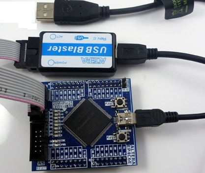
Рис. 1 — Демоплата Cyclone IV 4 FPGA Core Board
На плате (Рис. 1) установлен чип EP4CE6E22C8N, его характеристики:
| Вид ресурса | Краткое описание | Количество |
|---|---|---|
| Logic elements (Les) | Число логических блоков — ячеек, основная характеристика, по которым мы можем сравнивать «мощность» чипов, любая синтезированная логика будет затрачивать данные блоки | 6,272 |
| Embedded memory (Kbits) | Встроенной памяти, пока для нас не важная характеристика | 270 |
| Embedded 18×18 multipliers | Встроенных аппаратных умножителей, очень важный параметр в цифровой обработке сигналов, вся мощь ПЛИС раскрывается, когда несколько умножителей работают параллельно | 15 |
| General-purpose PLLs | Узлов фазовой автоподстройки частоты, пока не важная характеристика, упрощает синхронизацию устройств, работающих на разных частотах | 2 |
| Global Clock Networks | Количество частотных доменов, пока не важная характеристика | 10 |
| User I/O Banks | Число раздельных пользовательских банков ввода-вывода, пока не важная характеристика | 8 |
| Maximum user I/O | Число пользовательских пинов ввода-вывода, мы можем подключить любые устройства, как например к Ардуино | 91 |
На плате установлено:
- Флэш память – при подаче питания ПЛИС будет сконфигурирована в реализацию во флеш памяти. Вы можете синтезировать свой проект и записать в эту флэш
- Кварц 25 Мгц – генератор опорной тактовой частоты, именно на этой частоте будут работать все наши проекты, наша ПЛИС может поддерживать до 10 таких каналов.
- Светодиоды – 10, кнопки – 2.
- Пины ввода-вывода 61 + 2 земля, 1 не соединен. Можно подключить разнообразные устройства. ЦАП-АЦП, акселерометры и гироскопы, символьный и графические дисплеи, как и у Ардуино.
- Питание через USB, или внешнее 5В.
В комплекте также идет программатор JTAG, Altera USB Blaster.
2. Среда Quartus II и наш первый проект
Для работы с данной ПЛИС нам нужно скачать официальную среду разработки — Quartus II Web Edition, она бесплатная. Заходим на официальный сайт http://dl.altera.com/15.0/?edition=web, на момент написания версия 15.0 самая новая, если вышла новее, скачиваем ее.
Выбираем:
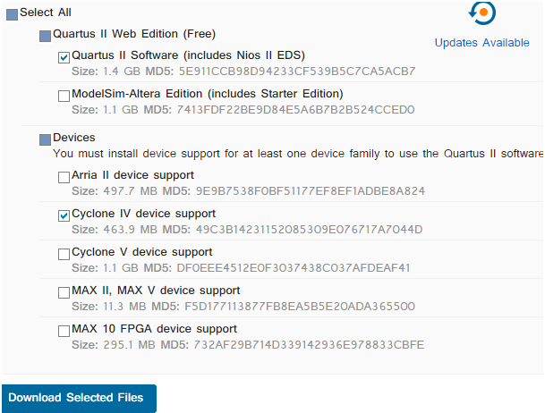
Рис. 2 — выбираем необходимые продукты Altera
И жмем кнопку скачать (Download Selected Files). После чего нам предложат зарегистрироваться, регистрируемся, скачиваем и устанавливаем.
Создадим свой первый проект.
Запускаем Quartus, выбираем главное меню File -> New Project Wizard, появляется окно введения, жмем next. Далее нужно указать каталог для проекта и его имя, третье поля – имя верхнего модуля, попозже увидите, что это. Выбираем папку, куда хотим сохранить проект и придумываем имя, у меня test1.
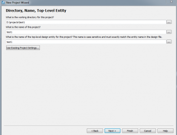
Рис. 3 — окно мастра нового проекта
Жмем next, у нас спрашивают, пустой проект (empty project) или шаблон (Project template). Оставляем пустой, next. Дальше нас просят добавить существующие файлы, у нас ничего нет, поскольку мы только начинаем свой путь, жмем next.
Далее нам необходимо выбрать наш чип, это можно сделать в любое время. Выбираем как на рисунке, Family – Cyclone IV E, specific device selected in “Available devices” и выбираем наш чип EP4CE6E22C8N, он в самом начале. Если у вас другой, найдите свой, это важно. Жмем next.
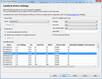
Рис. 4 — Окно мастера нового проекта, выбор нужного чипа
Появится окно — выбора средств проектирования, отладки, пока это пропускаем, нажимаем next и затем finish.
Далее главное меню Assignments -> Device, здесь можно выбрать чип (нашу ПЛИС), выбираем если не выбрали, нажимаем кнопку «Device and Pin Options».
Рис. 5 — Окно «Assinments-Deice»
В окне выбираем пункт «Unused pins». Эта настройка определяет, что будет с неподключенными пинами. Это может быть важно, в своем проекте вы вряд ли используете все пины, а не подключенные могут быть на деле соединены с землей или питанием (ну мало ли, кто разводил плату). Если вы подадите единичку на заземленный пин, то он сгорит, поэтому нужно внимательно следить за этим.
По умолчанию неиспользуемые пины «As input tri-stated with weak pull-up» (пины для ввода, находятся в третьем состоянии с высоким импедансом, со слабой подтяжкой по питанию), можно оставить или выбрать «As input tri-stated». Про подтягивающий резистор можете прочитать на википедии https://ru.wikipedia.org/wiki/Подтягивающий_резистор. В цифровой технике может быть три состояния, логическая единица – это напряжение питания или высокий уровень, логический ноль – это когда вывод подключен к земле или низкий уровень и высокоимпедансное состояние. Высокоимпедансное состояние — это когда пин имеет очень высокое сопротивление и практически не влияет на провод, к которому подключен, такое состояние нужно, например, при организации шин, когда множество устройств подключены к одному проводу и не активные устройства не мешают работе.
Рис. 6 — Окно «Device and Pin Options», Unused Pins
Далее нам нужно настроить пины, это нужно чтобы сигнал шел на нужные нам ножки чипа, ведь изначально Quartus не знает, что куда подключено и как именно осуществлена разводка платы.
Подключаем это все в «Assignment Editor»
Рис. 7 — Вызов «Assignment Editor» из меню или панели
В появившемся окне делаем как у меня, ну или если совсем правильно, то согласно схеме вашей платы.
Рис. 8 — Assinement Editor
В колонке «To» вписываем имя входа или выхода. В колонке «Assignment Name» выбираем «Location». В колонке «Value» номер контакта микросхемы, согласно схемы платы (у меня номера пинов написаны прямо на плате).
Также нужно указать, что делать с кнопками, которые одной ногой подключены к земле, а другой ко входу чипа. При нажатии на ноге будет низкий уровень, а вот без нажатия, непонятно, нога чипа будет просто висеть в воздухе, что очень плохо. Нужно подтянуть к питанию вход чипа либо резистором на плате, либо боле элегантным способом в «Assignments Editor». В колонке «Assignment Name» выбираем «Weak Pull Up resistor» для группы key* (группа обозначается через звездочку).
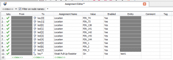
Рис. 9 — Assignment Editor
Нажимаем сохранить.
Далее нужно создать описание модуля верхнего уровня, который будет работать непосредственно с ножками чипа, все остальные модули будут работать только с ним. В главном меню жмем New, и выбираем «Design Files-> Block Diagram/Schematic File».
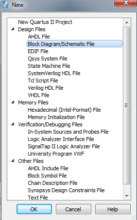
Рис. 10 — Диалог новых файлов
В открывшемся окне выбираем инструмент «Pin Tool» и располагаем вход и выход (пины ввода и вывода) на диаграмме. Переименовываем вход как key[0], выход как led[0] и соединяем их проводником. Сохраняем и нажимаем «Start Compilation».
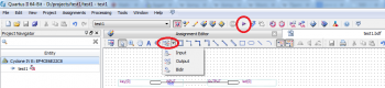
Рис. 11 — Окно графического описания, выделены Pin Tool и Start Compilation
После компиляции у нас возникли предупреждения, пока игнорируем их, они касаются неподключенных пинов, отсутствия тактового сигнала и описания для «Timing Analyzer».
Подключаем демоплату и программатор, выбираем инструмент «Programmer». В окне должно значиться «USB-Blaster [USB-..]», если нет то нажимаем «Hardware Setup» и пытаемся разобраться почему нет, скорее всего не установлены драйвера, смотрим в устройства Windows, ищем неопределенные устройства, может с кабелем проблема. Если все хорошо нажимаем «Auto Detect» и выбираем наш чип.
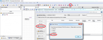
Рис. 12 — Окно Programmer
Нажимаем двойным щелчком мыши в поле «File» и выбираем файл для записи на ПЛИС (находиться в папке output_files нашего проекта), ставим галочку в поле «Program / Configure», и нажимаем кнопку «Start».
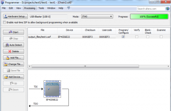
Рис. 13 — Окно Programmer, наш чип уже сконфигурирован
Поздравляю с первой конфигурацией ПЛИС! Диод D1 должен светиться, при нажатии key1 должен гаснуть (так как кнопка замыкает ножку с землей), далее мы с этим что-нибудь сделаем)
Вторая часть
Теги:
Hi I have just gotten a custom FPGA board in house and I am having trouble
programming it.
The FPGA I am using the Actel(Microsemi) Igloo AGL250V2-FGG1441
There is a 10 pin JTAG header on the board.
And I am using Microsemi's FlashPro3 to program it.
The header of the FlashPro3 is 12 pins. There is a extra pin called
VJTAGENB - that is used for IGLOO nano devices so I have left that pin
unconnected.
When I try and program the device with FlashPro I get the following error
messages:
Error: programmer '71917' : Signal Integrity Failure
       Integrity Check Pattern Not Found.
       Integrity Check Pattern :
       550FAAF000FF0000FFFF
       IrScan Error.
       TDO stuck at 0
       Chain Analysis Failed.
Error: programmer '71917' : Data Bit length : 8272
Error: programmer '71917' : Compare Data  : 000108080008649......
Error: programmer '71917' : Scan Chain FAILED.

I have tried two board and they get the same error. I have also scoped the
JTAG lines and they look the same of two board. The trst seems to stay low
and tms seems to switch up and down at higher fequecy then tck before
settling on low. Not sure how to post the scope pictures here. Let me know
if you want to see them or any of info I forgot to add.

The igloo app note, says that this error could mean by a broken td0 net,
are there any other possible reasons.


---------------------------------------
Posted through http://www.FPGARelated.com
Reply by rickman ●May 22, 20142014-05-22
On 5/22/2014 2:45 PM, elenappli wrote:> Hi I have just gotten a custom FPGA board in house and I am having trouble > programming it. > The FPGA I am using the Actel(Microsemi) Igloo AGL250V2-FGG1441 > There is a 10 pin JTAG header on the board. > And I am using Microsemi's FlashPro3 to program it. > The header of the FlashPro3 is 12 pins. There is a extra pin called > VJTAGENB - that is used for IGLOO nano devices so I have left that pin > unconnected. > When I try and program the device with FlashPro I get the following error > messages: > Error: programmer '71917' : Signal Integrity Failure > Integrity Check Pattern Not Found. > Integrity Check Pattern : > 550FAAF000FF0000FFFF > IrScan Error. > TDO stuck at 0 > Chain Analysis Failed. > Error: programmer '71917' : Data Bit length : 8272 > Error: programmer '71917' : Compare Data : 000108080008649...... > Error: programmer '71917' : Scan Chain FAILED. > > I have tried two board and they get the same error. I have also scoped the > JTAG lines and they look the same of two board. The trst seems to stay low > and tms seems to switch up and down at higher fequecy then tck before > settling on low. Not sure how to post the scope pictures here. Let me know > if you want to see them or any of info I forgot to add. > > The igloo app note, says that this error could mean by a broken td0 net, > are there any other possible reasons.I think you mean a broken tdo net. The point is the TDO signal is not going to the 1 state at the JTAG interface. It could be a TDO failure or any of the other JTAG signals. Can you verify connectivity from the JTAG connector to the FPGA pins? Do you have all the right power supply voltages on the FPGA pins including the I/O supply voltages? JTAG should take priority over all other control pins to the FPGA so the configuration interface signals shouldn't matter, just the JTAG pins. -- Rick
Reply by ●May 25, 20142014-05-25
Is it possible you have the pin assignments mixed up, having TMS toggle faster than TCK is a little unusual?
Other than that an open/short on any of the signals could result in the error you see.
Reply by Darko8 ●June 3, 20142014-06-03
>Hi I have just gotten a custom FPGA board in house and I am havingtrouble>programming it. >The FPGA I am using the Actel(Microsemi) Igloo AGL250V2-FGG1441 >There is a 10 pin JTAG header on the board. >And I am using Microsemi's FlashPro3 to program it. >The header of the FlashPro3 is 12 pins. There is a extra pin called >VJTAGENB - that is used for IGLOO nano devices so I have left that pin >unconnected. >When I try and program the device with FlashPro I get the following error >messages: >Error: programmer '71917' : Signal Integrity Failure > Integrity Check Pattern Not Found. > Integrity Check Pattern : > 550FAAF000FF0000FFFF > IrScan Error. > TDO stuck at 0 > Chain Analysis Failed. >Error: programmer '71917' : Data Bit length : 8272 >Error: programmer '71917' : Compare Data : 000108080008649...... >Error: programmer '71917' : Scan Chain FAILED. > >I have tried two board and they get the same error. I have also scopedthe>JTAG lines and they look the same of two board. The trst seems to staylow>and tms seems to switch up and down at higher fequecy then tck before >settling on low. Not sure how to post the scope pictures here. Let meknow>if you want to see them or any of info I forgot to add. > >The igloo app note, says that this error could mean by a broken td0 net, >are there any other possible reasons. > > > >--------------------------------------- >Posted through http://www.FPGARelated.com >Hi, In my case I had to wire agl_trst to VCC_JTAG to be able to connect to Igloo Nano Starter board, since my JTAG programmer lack TRST line (Altium JTAG). Regards, Darko --------------------------------------- Posted through http://www.FPGARelated.com
 Loading…

Phaser® 7800
Color Printer
Phaser® 7800
Service Manual
Xerox Internal-Use Only

Phaser 7800 Service Manual
Service Documentation
Phaser 7800 Service Manual
705P01307
BUS Update — 10/25/2011
November 2011
Xerox Corporation
Content Development and Language Services — North America
26600 Parkway — Bldg. 60
P.O. Box 1000, M/S 7060-776
Wilsonville, OR 97070-1000
NOTICE: All service documentation is supplied to Xerox external customers for informational purposes only. Xerox service documentation is intended for use by certified, product trained service personnel only. Xerox does not warrant or represent that such documentation is complete, nor does Xerox represent or warrant that it will notify or provide to such customer any future changes to this documentation. Customer performed service of equipment, or modules, components or parts of such equipment may affect the warranty offered by Xerox with respect to such equipment. You should consult the applicable warranty for its terms regarding customer or third party provided service. If the customer services such equipment, modules, components or parts thereof, the customer releases Xerox from any and all liability for the customer actions, and the customer agrees to indemnify, defend and hold Xerox harmless from any third party claims which arise directly or indirectly from such service.
© 2011 Xerox Corporation. All Rights Reserved. Unpublished rights reserved under the copyright laws of the United States. Contents of this publication may not be reproduced in any form without permission of Xerox Corporation.
Copyright protection claimed includes all forms of matters of copyrightable materials and information now allowed by statutory or judicial law or hereinafter granted, including without limitation, material generated from the software programs which are displayed on the screen such as styles, templates, icons, screen displays, looks, etc.
Xerox technical training materials and service manuals are intended for use by authorized Xerox service technicians and service partners only and are not for resale. These materials may not be distributed, copied or otherwise reproduced without prior written consent from Xerox Corporation.
XEROX® and XEROX and Design®, Phaser®, PhaserSMART®, PhaserMeter, CentreWare®, PrintingScout®, Walk-Up®, WorkCentre®, FreeFlow®, SMARTsend®, Scan to PC Desktop®, MeterAssistant®, SuppliesAssistant®, Xerox Secure Access Unified ID System®, Xerox Extensible Interface Platform®, ColorQube®, Global Print Driver®, and Mobile Express Driver® are trademarks of Xerox Corporation in the United States and/or other countries.
Adobe® Reader®, Adobe Type Manager®, ATM™, Flash®, Macromedia®, Photoshop®, and PostScript® are trademarks of Adobe Systems Incorporated in the United States and/or other countries.
Apple®, AppleTalk®, Bonjour®, EtherTalk®, Macintosh®, Mac OS®, and TrueType® are trademarks of Apple Computer, Inc. in the United States and/or other countries.
HP-GL®, HP-UX®, and PCL® are trademarks of Hewlett-Packard Corporation in the United States and/or other countries.
IBM® and AIX® are trademarks of International Business Machines Corporation in the United States and/or other countries.
Microsoft®, Windows Vista®, Windows®, and Windows Server® are trademarks of Microsoft Corporation in the United States and other countries.
Novell®, NetWare®, NDPS®, NDS®, IPX™, and Novell Distributed Print Services™ are trademarks of Novell, Inc. in the United States and other countries.
SGI® and IRIX® are trademarks of Silicon Graphics International Corp. or its subsidiaries in the United States and/or other countries.
Sun, Sun Microsystems, and Solaris are trademarks or registered trademarks of Oracle and/or its affiliates in the United States and other countries.
UNIX® is a trademark in the United States and other countries, licensed exclusively through X/ Open Company Limited.
As an ENERGY STAR® partner, Xerox Corporation has determined that this product meets the ENERGY STAR guidelines for energy efficiency. The ENERGY STAR name and logo are registered U.S. marks.
|
BUS Update 10/25/2011 — Xerox Internal Use Only |
November 2011 |
Phaser 7800 Service Manual

Introduction
|
About this Manual …………………………………………………………………………………………….. |
iii |
|
Organization…………………………………………………………………………………………………….. |
iii |
|
How to Use this Manual …………………………………………………………………………………….. |
iv |
|
Power Safety……………………………………………………………………………………………………. |
iv |
|
Service Safety Summary……………………………………………………………………………………. |
iv |
|
Moving the Printer …………………………………………………………………………………………….. |
vi |
|
Serial Number Format……………………………………………………………………………………….. |
vii |
|
Symbols Used on the Printer ……………………………………………………………………………… |
viii |
|
Electrostatic Discharge Precautions ……………………………………………………………………. |
x |
|
Regulatory Requirements ………………………………………………………………………………….. |
x |
|
Translation of Warnings …………………………………………………………………………………….. |
xii |
|
Phaser 7800 Overview………………………………………………………………………………………. |
xiii |
|
Printer Configurations ……………………………………………………………………………………….. |
xiii |
|
Parts of Phaser 7800 ………………………………………………………………………………………… |
xiv |
|
Phaser 7800 Options ………………………………………………………………………………………… |
xvi |
|
Control Panel Configurations ……………………………………………………………………………… |
xviii |
|
Routine Maintenance Items ……………………………………………………………………………….. |
xix |
|
Consumables …………………………………………………………………………………………………… |
xx |
|
Specifications …………………………………………………………………………………………………… |
xx |
|
Physical Dimensions and Clearances………………………………………………………………….. |
xxv |
|
Toner Cartridge Life ………………………………………………………………………………………….. |
xxvii |
|
Maintenance Function……………………………………………………………………………………….. |
xxvii |
|
Reference Pages and Troubleshooting Test Pages ………………………………………………. |
xxviii |
|
Acronyms and Abbreviations ……………………………………………………………………………… |
xxix |
|
BUS Update 10/25/2011 — Xerox Internal Use Only |
November 2011 |
Introduction |
|
Phaser 7800 Service Manual |
i |

About this Manual
The Phaser 7800 Service Manual is the primary document used for diagnosing, repairing, maintaining, and troubleshooting the printer. The Service Manual is the controlling publication for a service call. Information on using this document is found in the Introduction section. To ensure understanding of this product, complete the Xerox Service Training Program for this particular printer.
Service Manual Revision
Updates are issued as the printer changes or as corrections are identified.
Technical Support Information
For manual updates, Service Bulletins, knowledge base, and technical support, go to:
•Xerox Global Service Net — https://www.xrxgsn.com/secure/main.pl
For further technical support, contact your assigned Xerox Technical Support for this product.
Organization
The titles of the sections and a description of the information contained in each chapter are contained in the following paragraphs:
Introduction and General Information
This chapter contains documentation organization, symbology and nomenclature, translated warnings, safety symbols, regulatory requirements, and general information about the printer.
Chapter 1 Service Call Procedures
This chapter contains procedures to be taken during a service call and in what sequence they are to be completed. This is the entry level for all service calls.
Chapter 2 Status Indicator RAPs
This chapter contains descriptions of the diagnostic aids for troubleshooting that include Power On Self Test (POST), Fault Codes and Messages procedures.
Chapter 3 Image Quality
This chapter contains the diagnostic aids for troubleshooting image quality problems, as well as image quality specifications and image defect samples.
Chapter 4 Repairs/Adjustments
This chapter contains the removal, replacement, and adjustments procedures.
Repairs
Repairs include procedures for removal and replacement of spare parts listed in the Parts List. Use the repair procedures for the correct order of removal and replacement, for warnings, cautions, and notes.
Adjustments
Adjustments include procedures for adjusting the parts that must be within specification for the correct operation of the printer. Use the adjustment procedures for the correct sequence of operation for specifications, warnings, cautions and notes.
Chapter 5 Parts List
This chapter contains exploded views of the print engine and optional Field Replaceable Units (FRUs), as well as part numbers for orderable parts and illustrated Parts List.
Chapter 6 General Troubleshooting
This chapter contains details of the embedded Service Diagnostics test suite, as well as troubleshooting procedures for printer problems not related to a specific fault code.
Chapter 7 Wiring Data
This chapter contains drawings, lists of plug/jack locations, and diagrams of the power distribution wire networks in the printer.
Chapter 8 Theory of Operation
This chapter contains detailed functional information on the print engine components.
|
BUS Update 10/25/2011 — Xerox Internal Use Only |
November 2011 |
Introduction |
|
About this Manual, Organization |
||
|
Phaser 7800 Service Manual |
iii |

How to Use this Manual
Always start with the Service Call Procedures in Chapter 1. Perform Initial Actions and verify the problem, then follow the directions provided.
The power cord is attached to the printer as a plug-in device on the side of the printer. If it is necessary to disconnect all electrical power from the printer, disconnect the power cord from the electrical outlet.
Power Safety
Power Source
For 115 VAC printers, do not apply more than 135 volts RMS between the supply conductors or between either supply conductor and ground. For 230 VAC printers, do not apply more than 254 volts RMS between the supply conductors or between either supply conductor and ground. Use only the specified power cord and connector. This manual assumes that the reader is a qualified service technician.
Plug the three-wire power cord (with grounding prong) into a grounded AC outlet only. If necessary, contact a licensed electrician to install a properly grounded outlet. If the product loses its ground connection, contact with conductive parts may cause an electrical shock. A protective ground connection by way of the grounding conductor in the power cord is essential for safe operation.
Disconnecting Power
Disconnect the power cord in the following cases:
•if the power cord or plug is frayed or otherwise damaged,
•if any liquid or foreign material is spilled into the product,
•if the printer is exposed to any excess moisture,
•if the printer is dropped or damaged,
•if you suspect that the product needs servicing or repair,
•whenever you clean the product.
Service Safety Summary
General Safety
The printer and recommended supplies have been designed and tested to meet strict safety requirements. Attention to the following information will ensure the continued safe operation of the printer.
Electrical Safety
•Use the power cord supplied with the printer.
•Plug the power cord directly into a properly grounded electrical outlet.
•Do not use a ground adapter plug to connect the printer to an electrical outlet that does not have a ground connection terminal.
•Do not use an extension cord or power strip.
•Do not place the printer in an area where people might step on the power cord.
•Do not place objects on the power cord.
•Do not block the ventilation openings. These openings are provided to prevent overheating of the printer.
•Do not drop paper clips or staples into the printer.
WARNING
Switch off the electricity to the machine. Disconnect the power cord from the customer supply while performing tasks that do not need electricity. Electricity can cause death or injury. Moving parts can cause injury.
DANGER: Mettez la machine hors tension. Déconnectez le cordon d’alimentation de l’alimentation du client lorsque vous réalisez des tâches qui ne nécessitent pas d’électricité. L’électricité peut être à l’origine de blessures, voire d’un accident mortel. Les pièces amovibles peuvent être à l’origine de blessures.
AVVERTENZA: Spegnere la macchina. Scollegare il cavo di alimentazione dall’alimentatore quando si eseguono attività che non richiedono elettricità. L’elettricità può causare morte o lesioni personali. Le parti in movimento possono causare lesioni personali.
VORSICHT: Schalten Sie die Stromversorgung der Maschine ab. Ziehen Sie das Stromkabel ab, wenn Sie Aufgaben ausführen, für die keine Stromversorgung benötigt wird. Stromschläge können Todesfällen oder Verletzungen verursachen. Bewegliche Teile können zu Verletzungen führen.
AVISO: Apague la electricidad de la máquina. Desconecte el cable de alimentación eléctrica de la toma de pared mientras esté realizando tareas que no necesiten corriente. La electricidad puede causar daños o la muerte. Las partes móviles pueden causar daños.
WARNING
Do not switch on the electricity to the machine while a ground circuit is disconnected. Ground circuits ensure that the machine remains safe during a fault condition.
DANGER: Ne pas mettre la machine sous tension si un circuit de mise à la masse est déconnecté. Les circuits de mise à la masse permettent de garantir la sécurité de la machine lors d’un incident.
AVVERTENZA: Non accendere la macchina se uno dei conduttori di terra non è connesso. In caso di guasti elettrici, tali conduttori garantiscono la sicurezza del sistema.
VORSICHT: Stromzufuhr zum Gerät nicht einschalten, wenn keine Erdung gegeben ist.
AVISO: No encienda la máquina mientras esté deconectado algún circuito de tierra. Los circuitos de tierra mantienen la seguridad de la máquina en las situaciones de averías o errores.
Maintenance Safety
•Do not attempt any maintenance procedure that is not specifically described in the documentation supplied with the printer.
•Do not use aerosol cleaners. The use of supplies that are not approved may cause poor performance and could create a hazardous condition.
•Do not burn any consumables or routine maintenance items. For information on Xerox supplies recycling programs, go to www.xerox.com/gwa.
|
Introduction |
November 2011 |
BUS Update 10/25/2011 — Xerox Internal Use Only |
|
How to Use this Manual, Service Safety Summary |
||
|
iv |
Phaser 7800 Service Manual |

Operational Safety
The printer and supplies were designed and tested to meet strict safety requirements. These include safety agency examination, approval, and compliance with established environmental standards.
Pay attention to these safety guidelines to ensure the continued, safe operation of the printer.
•Use the supplies specifically designed for your printer. The use of unsuitable materials may cause poor performance and a possible safety hazard.
•Follow all warnings and instructions marked on, or supplied with, the printer, options and supplies.
WARNING
Use only Xerox materials and components. This product is safety certified using Xerox materials and components. The use of non Xerox materials and components may invalidate the safety certificate.
DANGER: N’utilisez que des matières premières et des composants Xerox. La sécurité du produit est assurée dans le cadre de son utilisation avec des matières premières et des composants Xerox. L’utilisation de matières premières et de composants autres que ceux de Xerox risque d’invalider le certificat de sécurité.
AVVERTENZA: Utilizzare solo materiali e componenti Xerox per avvalersi della certificazione di protezione. L’utilizzo di materiali e componenti non Xerox può rendere nulla la certificazione di protezione.
VORSICHT: Verwenden Sie nur Materialien und Komponenten von Xerox. Dieses Produkt besitzt die Sicherheitszertifizierung bei Verwendung von Xerox-Materialien und -Komponenten. Die Verwendung von Materialien und Komponenten anderer Hersteller setzt möglicherweise das Sicherheitszertifikat außer Kraft.
AVISO: Utilice solo los materiales y componentes Xerox. Este producto dispone de un certificado de seguridad si se utilizan los materiales y componentes Xerox. Este certificado de seguridad no será válido si se utilizan materiales y componentes que no sean de Xerox.
NOTE: The Total Satisfaction Guarantee is available in the United States and Canada. Coverage may vary outside these areas; please contact your local representative for details.
General Guidelines
For qualified service personnel only — Refer also to the preceding Power Safety Precautions.
Avoid servicing alone — Do not perform internal service or adjustment of this printer unless another person capable of rendering first aid or resuscitation is present.
Use care when servicing with power — Dangerous voltages may exist at several points in this printer. To avoid personal injury, do not touch exposed connections and components while power is on. Disconnect power before removing the power supply shield or replacing components.
Do not wear jewelry — Remove jewelry prior to servicing. Rings, necklaces and other metallic objects could come into contact with dangerous voltages and currents.
Warning Labels
Read and obey all posted warning labels. Throughout the printer, warning labels are displayed on potentially dangerous components. As you service the printer, check to make certain that all warning labels remain in place.
Safety Interlocks
Make sure all covers are in place and all interlock switches are functioning correctly after you have completed a printer service call. If you bypass an interlock switch during a service call, use extreme caution when working on or around the printer.
|
BUS Update 10/25/2011 — Xerox Internal Use Only |
November 2011 |
Introduction |
|
Service Safety Summary |
||
|
Phaser 7800 Service Manual |
v |

Moving the Printer |
Repacking Procedure |
||
|
• |
Use the power switch to turn Off the printer, and unplug all cables and cords. Do not turn |
1. |
Remove the Imaging Unit (Y/M/C/K) (REP 8.1). |
|
the printer Off by pulling the power cord or using a power-strip with an On/Off switch. |
2. |
Remove the Toner Cartridge (Y/M/C/K) (REP 5.1). |
|
|
• |
The printer is heavy and must be lifted by three people. |
3. |
Remove the Waste Cartridge (REP 8.9). |
|
4. |
Remove the IBT Belt Cleaner Assembly (REP 6.1). |
||
|
5. |
Remove the Front Cover Assembly and Inner Cover Assembly (REP 19.1). |
||
|
6. |
Remove the Top Cover (REP 19.2). |
||
|
7. |
Cut card board to 4 pieces at approximately 1 x 1.5 inch for each piece. |
||
|
8. |
Cover the toner ports with the card boards. |
Figure 1 Printer Lifting Technique
Repacking the Printer
When shipping the printer, repack the printer using the original packing material and boxes or a Xerox packaging kit. Instructions for repacking the printer are included in the kit. If you do not
have all the original packaging, or are unable to repackage the printer, contact your local Xerox
Figure 2 Covering the Toner Ports
service representative.
CAUTION
Failure to repackage the printer properly for shipment can result in damage to the printer. Damage to the printer caused by improper packaging is not covered by the Xerox warranty, service agreement, or Total Satisfaction Guarantee.
|
Introduction |
November 2011 |
BUS Update 10/25/2011 — Xerox Internal Use Only |
|
Moving the Printer |
||
|
vi |
Phaser 7800 Service Manual |

9.Use the tape from the Repack Kit and cut the tape to secure the Card Boards at the toner ports.
Figure 3 Securing the Card Boards
10. Reassemble the printer and follow the instructions included with the repair kit.
Serial Number Format
Changes to Xerox products are made to accommodate improved components. As improvements are made, part numbers may change from those appearing in this section. To get the latest part, provide the following information when ordering:
•Component’s part number
•Product type or configuration number
•Serial number of the printer
The nine-digit serial number has the following format:
•PPPRSSSSS
•PPP = Three digit alphanumeric product code
•R = Single digit numeric revision digit, 0-9. To be rolled when a major product change occurs and initiated with a change request.
|
Table 1 Product Code |
||
|
Product |
Product Code |
|
|
7800, 110V Engine |
AT0 |
|
|
7800V, 220V Engine |
AT1 |
|
NOTE: Not all of the serial number will be used. This is a buffer in case additional units are built by Fuji Xerox for each model of printer during pre-production.
Table 2 Serial Number
|
Product |
Starting Serial Number |
Ending Serial Number |
|
7800_DN, 110V Engine |
205601 |
224500 |
|
7800_YDN, 110V Engine |
224501 |
225500 |
|
7800V_DN, 220V Engine |
225601 |
250500 |
Serial numbers between 200601 — 205600 are reserved for XOG FIC sites if reserialization is needed. A serial number break or a new serial number range will be provided when a major product change occurs.
|
BUS Update 10/25/2011 — Xerox Internal Use Only |
November 2011 |
Introduction |
|
Moving the Printer, Serial Number Format |
||
|
Phaser 7800 Service Manual |
vii |

Examples
110V Engine
AT0220800
Product code for 110V printer = AT0 Serial number for 7800_DN = 220800
220V Engine
AT1227360
Product code for 220V printer = AT1 Serial number for 7800V_DN = 227360
Symbols Used on the Printer
Warnings, Cautions, and Notes
Be aware of all symbols and terms when they are used, and always read Note, Caution, and Warning statements.
A translated version of all warnings is in Translation of Warnings section.
Warnings, Cautions, and Notes can be found throughout the service manual. The words WARNING or CAUTION may be listed on an illustration when the specific component associated with the potential hazard is pointed out; however, the message of the WARNING or CAUTION is always located in the text. Their definitions are as follows:
Label Placement and Layout Example
The Serial Number Label will be applied inside the left door on the right side of the frame as shown in photo below:
WARNING
A warning is used whenever an operating or maintenance procedure, practice, condition or statement, if not strictly observed, could result in personal injury.
DANGER: Une note Danger est utilisée chaque fois qu’une procédure d’utilisation ou de maintenance peut être cause de blessure si elle n’est pas strictement respectée.
AVVERTENZA: Un segnale di avvertenza è utilizzato ogni volta che una procedura operativa o di manutenzione, una pratica, una condizione o un’istruzione, se non strettamente osservata, potrebbe causare lesioni personali.
VORSICHT: Weist darauf hin, dass ein Abweichen von den angeführten Arbeitsund Wartungsanweisungen gesundheitliche Schäden, möglicherweise sogar schwere Verletzungen zur Folge haben kann.
AVISO:Un aviso se utiliza siempre que un procedimiento de operación o mantenimiento, práctica o condición puede causar daños personales si no se respetan estrictamente.
CAUTION
A Caution is used whenever an operating or maintenance procedure, a practice, condition, or statement, if not strictly observed, could result in damage to the equipment.
NOTE: A Note is used whenever it is necessary to highlight an operating or maintenance procedure, practice, condition, or statement.
Figure 1 Serial Number Location
|
Introduction |
November 2011 |
BUS Update 10/25/2011 — Xerox Internal Use Only |
|
Serial Number Format, Symbols Used on the Printer |
||
|
viii |
Phaser 7800 Service Manual |

Printer Safety Icons |
Static Caution |
|
The following precautionary symbols may appear on the printer. |
|
|
This symbol indicates hot surface on or in the printer. Use caution to avoid personal injury. |
Figure 1 Hot Surface Symbol
Use caution (or draws attention to a particular component).
Figure 2 Use Caution Symbol
Danger, High Voltage
Figure 3 High Voltage Symbol
Fuser Temperature
Figure 4 Fuser Temperature
Figure 5 Static Caution Symbol
Do not touch the item.
Figure 6 Do Not Touch Item Symbol
Do not burn the item.
Figure 7 Do Not Burn Item Symbol
Recycle the item.
Figure 8 Recycling Item Symbol
Protective Ground (Earth) symbol.
Figure 9 Protective Ground (Earth) Symbol
|
BUS Update 10/25/2011 — Xerox Internal Use Only |
November 2011 |
Introduction |
|
Symbols Used on the Printer |
||
|
Phaser 7800 Service Manual |
ix |
![]()
Electrostatic Discharge Precautions
Some semiconductor components, and the respective sub-assemblies that contain them, are vulnerable to damage by Electrostatic Discharge (ESD). These components include Integrated Circuits (ICs), Large-Scale Integrated circuits (LSIs), field-effect transistors, and other semiconductor chip components. The following techniques will reduce the occurrence of component damage caused by static electricity.
Be sure the power is off to the chassis or the circuit board, and observe all other safety precautions.
•Immediately before handling any semiconductor components assemblies, drain the electrostatic charge from your body. This can be accomplished by touching an earth ground source or by wearing a wrist strap device connected to an earth ground source. Wearing a wrist strap will also prevent accumulation of additional bodily static charges. Be sure to remove the wrist strap before applying power to the unit under test to avoid potential shock.
•After removing a static sensitive assembly from its anti-static bag, place it on a grounded conductive surface. If the anti-static bag is conductive, you may ground the bag and use it as a conductive surface.
•Do not use freon-propelled chemicals. These can generate electrical charges sufficient to damage some devices.
•Do not remove a replacement component or electrical sub-assembly from its protective package until you are ready to install it.
•Immediately before removing the protective material from the leads of a replacement device, touch the protective material to the chassis or circuit assembly into which the device will be installed.
•Minimize body motions when handling unpacked replacement devices. Motion such as your clothes brushing together, or lifting a foot from a carpeted floor can generate enough static electricity to damage an electro-statically sensitive device.
•Handle IC’s and Erasable Programmable Read-Only Memories (EPROM’s) carefully to avoid bending the pins.
•Pay attention to the direction of parts when mounting or inserting them on the Printed Circuit Boards (PCB’s).
Regulatory Requirements
Xerox has tested this printer to electromagnetic emission and immunity standards. These standards are designed to mitigate interference caused or received by this printer in a typical office environment.
United States (FCC Regulations)
This equipment has been tested and found to comply with the limits for a Class A digital device, pursuant to Part 15 of the FCC Rules. These limits are designed to provide reasonable protection against harmful interference when the equipment is operated in a commercial environment. This equipment generates, uses, and can radiate radio frequency energy. If it is not installed and used in accordance with these instructions, it may cause harmful interference to radio communications. Operation of this equipment in a residential area is likely to cause harmful interference in which case the user will be required to correct the interference at his/her own expense.
If this equipment does cause harmful interference to radio or television reception, which can be determined by turning the equipment off and on, the user is encouraged to try to correct the interference by one or more of the following measures:
•Reorient or relocate the receiver.
•Increase the separation between the equipment and receiver.
•Connect the equipment into an outlet on a circuit different from that to which the receiver is connected.
•Consult the dealer or an experienced radio/television technician for help.
Any changes or modifications not expressly approved by Xerox could void the user’s authority to operate the equipment. To ensure compliance with Part 15 of the FCC rules, use shielded interface cables.
Canada (Regulations)
This Class A digital apparatus complies with Canadian ICES-003.
Cet appareil numérique de la classe A est conforme à la norme NMB-003 du Canada.
|
Introduction |
November 2011 |
BUS Update 10/25/2011 — Xerox Internal Use Only |
|
Electrostatic Discharge Precautions, Regulatory Re- |
||
|
x |
Phaser 7800 Service Manual |

European Union
The CE mark applied to this product symbolizes Xerox’s declaration of conformity with the following applicable Directives of the European Union as of the dates indicated:
Figure 1 CE Symbol
•December 12, 2006: Low Voltage Directive 2006/95/EC
•December 15, 2004: Electromagnetic Compatibility Directive 2004/108/EC
This product, if used properly in accordance with the user’s instructions, is neither dangerous for the consumer nor for the environment.
To ensure compliance with European Union regulations, use shielded interface cables.
A signed copy of the Declaration of Conformity for this product can be obtained from Xerox.
Ozone Release
During print operation, a small quantity of ozone is released. This amount is not large enough to harm anyone adversely. However, be sure the room where the printer is being used has adequate ventilation, especially if you are printing a high volume of materials, or if the printer is being used continuously over a long period.
|
BUS Update 10/25/2011 — Xerox Internal Use Only |
November 2011 |
Introduction |
|
Regulatory Requirements |
||
|
Phaser 7800 Service Manual |
xi |

Translation of Warnings
General Usage
WARNING
Use only Xerox materials and components. This product is safety certified using Xerox materials and components. The use of non Xerox materials and components may invalidate the safety certificate.
DANGER: N’utilisez que des matières premières et des composants Xerox. La sécurité du produit est assurée dans le cadre de son utilisation avec des matières premières et des composants Xerox. L’utilisation de matières premières et de composants autres que ceux de Xerox risque d’invalider le certificat de sécurité.
AVVERTENZA: Utilizzare solo materiali e componenti Xerox per avvalersi della certificazione di protezione. L’utilizzo di materiali e componenti non Xerox può rendere nulla la certificazione di protezione.
VORSICHT: Verwenden Sie nur Materialien und Komponenten von Xerox. Dieses Produkt besitzt die Sicherheitszertifizierung bei Verwendung von Xerox-Materialien und -Komponenten. Die Verwendung von Materialien und Komponenten anderer Hersteller setzt möglicherweise das Sicherheitszertifikat außer Kraft.
AVISO: Utilice solo los materiales y componentes Xerox. Este producto dispone de un certificado de seguridad si se utilizan los materiales y componentes Xerox. Este certificado de seguridad no será válido si se utilizan materiales y componentes que no sean de Xerox.
WARNING
Do not touch the fuser while it is hot.
DANGER: Ne pas toucher au four pendant qu’il est encore chaud.
AVVERTENZA: Non toccare il fonditore quando è caldo.
VORSICHT: Fixierbereich erst berühren, wenn dieser abgekühlt ist.
AVISO: No toque el fusor mientras está caliente.
WARNING
Do not work in a confined space. 1 m (39 inches) space is needed for safe working.
DANGER: Ne pas travailler dans un espace restreint. 1 mètre d’espace est nécessaire pour un dépannage en toute sécurité.
AVVERTENZA: Non lavorare in uno spazio limitato; è necessario uno spazio di almeno un metro attorno alla macchina per la sicurezza dell’operatore.
VORSICHT: Nur mit ausreichendem Bewegungsspielraum (1 m) arbeiten.
AVISO: No trabaje en un espacio reducido. Se necesita 1 metro de espacio para trabajar con seguridad.
WARNING
USA and Canada. Do not install this printer in a hallway or exit route that does not have 1.12 m (44 inches) of space additional to the normal space requirements in front of the machine. To conform with fire regulations this additional 1.12 m (44 inches) of space is needed in front of the printer in hallway and exit routes.
DANGER : États-Unis et Canada. Si cette machine est installée dans un couloir ou une voie de sortie, 1,12 m (44 pouces) d’espace supplémentaire à l’espace normal doit être disponible devant la machine conformément aux normes de sécurité d’incendie.
AVVERTENZA: N/A
VORSICHT: N/A
AVISO: Estados Unidos y Canadá. No instale esta máquina en un corredor o ruta de salida que no tenga 1.12 m (44 pulgadas) de ancho delante de la máquina, sin incluir el espacio que ocupe la máquina. Este espacio adicional de 1.12 m (44 pulgadas) delante de la máquina en corredores y rutas de salida es necesario para cumplir los requisitos
de las normas sobre incendios.
Electrical
WARNING
Do not perform repair activities with the power on or electrical power supplied to the machine. The machine could activate and cause serious personal injury when the power is on or electrical power is supplied.
DANGER: Ne pas effectuer de dépannage avec le contact principal activé ou avec l’alimentation électrique appliquée à la machine: celle-ci pourrait démarrer et causer de graves blessures.
AVVERTENZA: Non effettuare alcuna riparazione con la macchina accesa o con l’alimentazione elettrica inserita. La macchina potrebbe avviarsi all’improvviso e causare gravi ferite.
VORSICHT: Es dürfen keine Reparaturarbeiten durchgeführt werden, solange das Gerät eingeschalten oder mit der Stromquelle verbunden ist. Das Gerät kann u.U in den AktivZustand übergehen und somit erhebliche körperliche Schäden verursachen.
AVISO: No realice reparaciones con la máquina encendida o conectada a la corriente. La máquina podría activarse y ocasionar daños personales graves.
WARNING
Use extreme care when working near this power supply. High voltage is present on the power supply when the machine is in standby mode. Contact with electrical components or high voltage cables represents a shock potential that could result in serious personal injury.
DANGER: Faire très attention en intervenant près de ce module d’alimentation. Une haute tension y est présente lorsque la machine est en mode d’attente. Tout contact avec les éléments électriques ou les câbles haute tension représente un risque de choc et de graves blessures.
AVVERTENZA: Fare estrema attenzione quando si lavora vicino a questo gruppo statico. Il gruppo statico è caricato ad alta tensione quando la macchina è in modalità standby. Il contatto con componenti sotto tensione o cavi elettrici comportano un seriopericolo di scossa elettrica e gravi ferite.
VORSICHT: Bei der Verwendung unterbrechungsfreier Stromversorgung benutzt äußerste Vorsichtkeit. Während die Machine sich im Energiespar-Modus befindet, steht es unter Hochspannung. Beim Umgang mit elektrischen Bauteilen und Hochspannungsleitungen erhöht sich das Unfallrisiko. Äußerste Vorsicht ist geboten.
AVISO: Tenga mucho cuidado al trabajar en las proximidades de la fuente de alimentación. Hay voltaje muy alto en la fuente de alimentación cuando la máquina se encuentra en el modo de espera. El contacto con componentes eléctricos o cables de alto voltaje representa peligro de descarga eléctrica que puede ocasionar daños personales
graves.
|
Introduction |
November 2011 |
BUS Update 10/25/2011 — Xerox Internal Use Only |
|
Translation of Warnings |
||
|
xii |
Phaser 7800 Service Manual |

Finisher
WARNING
Do not connect the finisher power cord directly to the AC wall outlet. The finisher cannot operate without the machine. The machine controls the distribution of electricity to the finisher for correct power on the power off sequencing.
DANGER: Ne pas connecter le cordon d’alimentation du module de finition directement sur la prise murale. Le module ne peut pas fonctionner sans la machine. Celle-ci contrôle la distribution d’électricité vers le module de finition lors des séquences de mises hors tension.
AVVERTENZA: non connettere il cavo elettrico della stazione di finitura direttamente a una presa a muro. La macchina non è in grado di funzionare indipendentemente dalla stampante, la quale ne gestisce totalmente i cicli di accensione e spegnimento.
VORSICHT: Netzstecker des Finisher nicht direkt an eine Netzsteckdose anschließen. Der Finisher kann nicht ohne das Document Centre betrieben werden. Die Stromversorgung zum Finisher zur richtigen Abschaltsequenz wird vom Document Centre gesteuert.
AVISO: No conecte el cable de alimentación de la acabadora directamente a la toma de corriente alterna. La acabadora no funciona sin la máquina. La máquina controla la distribución de energía eléctrica a la acabadora para la secuencia correcta de encendido y apagado.
Phaser 7800 Overview
The Phaser 7800 uses single-pass LED print heads with an electrophotographic four-color (YMCK) tandem architecture and intermediate transfer printing process. The Phaser 7800 delivers color and mono print speed at 45/45-ppm, and resolutions up to 1200 x 2400 dots-per- inch (dpi). The Phaser 7800 supports Adobe PostScript 3, PCL5, PCL6, USB 2.0, and 10/100/ 1000 Base-TX Ethernet. Additional features include a 4.3” touch screen display and a Hard Disk Drive. A Finisher with stacking, stapling, punching, and booklet making features is available with the Phaser 7800 per selected model.
Input trays can support up to 5 trays with 1500-Sheet High-Capacity Feeder or 2500-Sheet High-Capacity Feeder. Tray 1 supports up to 100 sheets of specialty paper, card stock, and envelopes. The standard paper input is 500 sheets and the maximum input with an optional Trays 3, 4, and 5 is 2500 sheets. Two output trays are included with the Phaser 7800; each output tray holds 250 sheets face down.
Printer Configurations
The Phaser 7800 is available in three configurations.
Table 1 Phaser 7800 Configurations
|
Features |
7800 DN |
7800 GX |
7800 DX |
||||
|
Processor and Clock |
1.33 GHz |
1.33 GHz |
1.33 GHz |
||||
|
Speed |
|||||||
|
Memory Configuration* |
2 GB |
2 GB |
2 GB |
||||
|
Print Speed |
45/45 |
45/45 |
45/45 |
||||
|
Adobe Postscript 3 Fonts |
Standard |
Standard |
Standard |
||||
|
PCL5 Fonts |
Standard |
Standard |
Standard |
||||
|
PCL6 Fonts |
Standard |
Standard |
Standard |
||||
|
USB 2.0 |
Standard |
Standard |
Standard |
||||
|
Ethernet Interface |
10/100/1000 |
10/100/1000 |
10/100/1000 |
||||
|
Base-TX |
Base-TX |
Base-TX |
|||||
|
Tray 1 (100 Sheet) |
Standard |
Standard |
Standard |
||||
|
Tray 2 (500 Sheet) |
Standard |
Standard |
Standard |
||||
|
Tray 3/4/5 1500-Sheet |
Optional |
Standard |
N/A |
||||
|
Feeder |
|||||||
|
Tray 3/4/5 2500-Sheet |
Optional |
N/A |
Standard |
||||
|
Feeder |
|||||||
|
Auto-Duplexer |
Standard |
Standard |
Standard |
||||
|
Hard Disk Drive |
160 GB |
160 GB |
160 GB |
||||
|
Advanced Finisher |
N/A |
Optional |
Optional |
||||
|
Professional Finisher |
N/A |
Optional |
Optional |
||||
|
Wireless LAN |
Optional |
Optional |
Optional |
||||
|
Printer Resolution (dpi) |
|||||||
|
• |
Standard |
• |
1200×600 |
• |
1200×600 |
• |
1200×600 |
|
• |
Enhanced |
• |
1200×1200 |
• |
1200×1200 |
• |
1200×1200 |
|
• |
Photo |
• |
2400×1200 |
• |
2400×1200 |
• |
2400×1200 |
* All configurations have one memory slot supporting 2 GB DDR2 DIMMs.
|
BUS Update 10/25/2011 — Xerox Internal Use Only |
November 2011 |
Introduction |
|
Translation of Warnings, Printer Configurations |
||
|
Phaser 7800 Service Manual |
xiii |

Parts of Phaser 7800 |
Left Front View of 7800DX Printer (with 2500-Sheet Feeder) |
Left Front View of 7800GX Printer (with 1500-Sheet Feeder) |
Figure 2 Left Front View with 2500-Sheet Feeder
Figure 1 Left Front View with 1500-Sheet Feeder
1. Left Side Door C
1. Left Side Door C
2. Tray 1 with Extension Tray
2. Tray 1 with Extension Tray
3. Left Side Door B
3. Left Side Door B
4. Left Side Door A
4. Left Side Door A
5. Left Side Door D
5. Left Side Door D
6. Control Panel
6. Control Panel
7. Output Tray
7. Output Tray
8. Center Output Tray
8. Center Output Tray
9. Secondary Power Switch
9. Secondary Power Switch
10. Main Power Switch
10. Main Power Switch
11. Front Door
11. Front Door
12. Tray 2
12. Tray 2
13. 2500-Sheet Feeder (Trays 3-5)
13. 1500-Sheet Feeder (Trays 3-5)
|
Introduction |
November 2011 |
BUS Update 10/25/2011 — Xerox Internal Use Only |
|
Parts of Phaser 7800 |
||
|
xiv |
Phaser 7800 Service Manual |

Left and Rear Views |
Hard Disk Drive |
|
|
The Phaser 7800 supports an internal Hard Disk Drive. The Hard Disk Drive has a minimum |
||
|
160 GB capacity. Features include: |
||
|
• |
Secure Print |
|
|
• |
Personal Print |
|
|
• Personal or Shared Saved Print |
||
|
• |
Disk Collation |
Figure 4 Hard Disk Drive
Figure 3 Left and Rear Views
1.USB Connection
2.USB Memory Port (for service only)
3.Ethernet Connection
4.Power Connector for Finisher
5.Power Connector for Printer
|
BUS Update 10/25/2011 — Xerox Internal Use Only |
November 2011 |
Introduction |
|
Parts of Phaser 7800 |
||
|
Phaser 7800 Service Manual |
xv |

Phaser 7800 Options
The Phaser 7800 options include:
•Wireless Adapter
•Heavy Media Kit
•Optional 1500-Sheet Feeder (Trays 3, 4, 5)
•Optional 2500-Sheet Feeder (Trays 3, 4, 5)
Wireless Adapter
The Wireless Network Adapter enables the printer to connect to a wireless network.
Heavy Media Kit
The Heavy Media Kit allows the printer to feed media (duplex) up to 350gsm. Refer to Gate 1 Spring removal procedure (REP 17.5) for how to remove the Spring.
Optional 1500-Sheet Feeder (Trays 3, 4, 5)
The Optional 1500-Sheet Feeder increases the input capacity of the printer and can be attached to the printer underneath Tray 2. Each tray holds up to 500 sheets of media. The Optional 1500-Sheet Feeder is customer installable.
Figure 1 Optional 1500-Sheet Feeder
Optional 2500-Sheet Feeder (Trays 3, 4, 5)
The Optional 2500-Sheet Feeder increases the input capacity of the printer and can be attached to the printer underneath Tray 2. Tray 3 holds up to 500 sheets and Trays 4 and 5 hold up to 1,000 sheets each. The Optional 2500-Sheet Feeder is customer installable.
Figure 2 Optional 2500-Sheet Feeder
|
Introduction |
November 2011 |
BUS Update 10/25/2011 — Xerox Internal Use Only |
|
Phaser 7800 Options |
||
|
xvi |
Phaser 7800 Service Manual |

Finisher
The Finisher is a customer install option and available in two models: Advanced and Professional.
Advanced Finisher
The Advanced Finisher consists of a Horizontal Transport and SB Finisher. The SB Finisher can collate, stack, staple, add a booklet crimp, saddle staple, and hole punch sets of prints.
The Advanced Finisher can stack up to 2000 sheets or 200 sets of 90 gsm or 20 lb letter/A4 size paper. For paper sizes greater than A4 LTR, the maximum number of sets is limited to 100.
The SB Finisher handles a variety of standard paper sizes, ranging from A4 SEF/ 8.5 x 11” up to A3/ 11 x 17”. The Center Tray has a capacity of 200 sheets of A3/11 x 17” paper. The Stacker Tray has a capacity of 2000 sheets of A4/ 8.5 x 11” or 1000 sheets of A3/ 11 x 17” paper.
|
Figure 3 Advanced Finisher |
|||
|
1. |
Front Transport Cover |
8. |
Booklet Maker |
|
2. |
2/3 Hole Punch Kit or 2/4 Hole Punch Kit |
9. |
Right Tray |
|
3. |
Hole Punch Waste Container |
10. |
Right Tray Extension |
|
4. |
Horizontal Transport |
11. |
Creaser Unit |
|
5. |
Finisher Top Cover |
12. |
Staple Cartridge |
|
6. |
Booklet Staple Cartridge |
13. |
Finisher Front Door |
|
7. |
Side Cover for Booklet Unit |
14. |
Finisher Front Cover |
Professional Finisher
The Professional Finisher includes a Booklet Maker.
•Top Tray: 500 sheets
•Stacking Tray: Up to 3000 sheets
•Stapling:
–Single (Front/ Rear), dual, and quadruple* (A A4/ Letter)
–Auto stapling (50 sheets maximum) — 24 lb/90 gsm
–Booklet stapling
–Supports Letter, Legal, Tabloid, A3, A4, B4 and B5 size
|
Figure 4 Professional Finisher |
|||
|
1. |
Center Tray |
7. |
Right Middle Tray |
|
2. |
Hole Punch Unit |
8. |
Staple Cartridge |
|
3. |
Hole Punch Waste Container |
9. |
Booklet Tray |
|
4. |
Finisher Front Door |
10. |
Booklet Staple Assembly |
|
5. |
Right Top Tray |
11. |
Booklet Maker |
6.Exit Cover
|
BUS Update 10/25/2011 — Xerox Internal Use Only |
November 2011 |
Introduction |
|
Phaser 7800 Options |
||
|
Phaser 7800 Service Manual |
xvii |

Control Panel Configurations
The Control Panel consists of one LED, one 4.3 inch Wide Video Graphics Array (WVGA) touch screen display, and 2 functional buttons. The touch screen is used to navigate the menu system, perform functions, and select modes of operation for the printer. The Control Panel contains various features include:
•Displays the current operating status of the printer.
•Provides access to print features.
•Provides access to reference materials.
•Provides access to Tools and Setup menus.
•Provides access to Troubleshooting menus and videos.
•Prompts user to load paper, replace supplies, and clear jams.
•Displays errors and warnings.
•Plays event-driven videos.
|
Figure 1 Phaser 7800 Control Panel |
||
|
1. |
Touch Screen |
Displays information and provides access to the printer functions |
|
2. |
Power Saver |
Enters Sleep mode, and exists Low Power or Sleep mode. |
|
3. |
Cancel |
Temporarily stops the current print job, allowing user to cancel or |
|
resume the job. |
Control Panel Special Functions
Table 1 Service Control Panel
|
Function |
Buttons Presses |
|
|
Enter Service Diagnostics |
From Ready to Print, press and hold the Pause button for 5 |
|
|
seconds, then press and release the Power Saver button to |
||
|
display the Service Diagnostics login screen. |
||
|
Reset Touchscreen Parameters |
From Ready to Print, press and hold the Power Saver button |
|
|
for 5 seconds, then press and release the Pause button to |
||
|
reset the Touchscreen to factory defaults and display the |
||
|
Control Panel calibration screen (GP 10 — Control Panel |
||
|
Troubleshooting). |
||
|
Override locked Service Tools |
At the login screen: |
|
|
menu using Service credentials |
User Name: !$ecivreS |
|
|
Passcode: 2732 |
||
|
Resetting the System Admin |
1. |
Obtain the printer serial number and page count. |
|
(SA) Pass Code |
2. |
Call the Welcome Center for a temporary pass code. |
|
3. |
Enter reset (not case sensitive) and temporary pass |
|
|
code at the login screen. |
||
|
NOTE: SA login credentials return to default values |
||
|
(ADMIN/1111) after 100 pages. |
||
|
Access Code |
• |
From Control Panel |
|
Printer > Tools > Setup > Service Tools > Service Diag- |
||
|
nostics |
||
|
• |
Enter code 6789 |
|
LED Indicators
|
Table 2 LED Indicators |
|
|
LED State |
Printer State |
|
Flashing Green |
If no error condition exists and print engine is busy or a job is being |
|
processed. |
|
|
Green |
No error or warning condition exists. |
|
Red |
An error condition exists. |
|
Amber |
No error condition exists and a warning condition exists. |
|
Introduction |
November 2011 |
BUS Update 10/25/2011 — Xerox Internal Use Only |
|
Control Panel Configurations |
||
|
xviii |
Phaser 7800 Service Manual |

LUI (Control Panel) Lock
•LUI Lock is stored on the SD Card.
•LUI Lock factory default for all items: Off.
•System Administrator (SA) user name and passcode are stored on the SD Card.
•System Administrator (SA) user name and passcode factory defaults: «admin», 1111.
•Service username and passcode: Available from Service.
•Service Access is stored on the SD Card.
•Service Access: Enabled.
•If LUI Lock is Off or Service and the SA are not logged in, all buttons are displayed with no key icon.
•If LUI Lock is On and neither Service nor the SA is logged in, the buttons of each lockable item is displayed with a key icon.
•The lockable items are:
–Print Reference Materials
–Tray Management
–Language / Keyboard
–Date / Time
–System Timeout
–Startup Page
–Network & USB
–Reprint Jammed Pages
–Security
–Output Settings
–Energy Saver
–PostScript
–Service Tools
•If an LUI button has no key icon, selecting it displays the button’s menu.
•If an LUI button has a key icon, selecting the button displays the passcode entry screen.
•If the SA user name and passcode are entered, the SA is logged in.
•If Service Access is Enabled and the Service user name and passcode are entered, Service is logged in.
•If either Service or the SA is logged in, the item is displayed.
•Service or the SA is logged out when the System Timeout expires or the Logout button is selected from the Home Page.
Interactions
If the user name «reset» is entered in the passcode entry screen, a passcode generated from the serial number and Total Impressions by a proprietary algorithm is valid until Total Impressions plus 100 is reached.
•The above allows service to help users who have forgotten or lost their SA user name and/or passcode. The customer can call for assistance and must provide the printer serial number and current Total Impressions, which uses a Xerox app to generate the passcode. This passcode works while the printer’s Total Impressions are from up to and including Total Impressions + 99. Note that the «reset» user name and special passcode also work in CWIS.
Routine Maintenance Items
A maintenance item is a printer part or assembly that has a limited life, and requires periodic replacement. Routine maintenance items are typically customer replaceable.
The following listed items have limited life and require periodic replacement.
NOTE: Print life is based on “typical” office printing and 5% coverage per color on 24 lb. paper. The 1,500,000 life is not guaranteed and varies depending on usage habits.
Figure 1 Routine Maintenance Items
Table 1 Phaser 7800 Maintenance Items
|
Item |
Description |
Print Life |
||
|
1 |
Transfer Roller |
200,000 pages |
||
|
2 |
Fuser |
360,000 pages |
||
|
3 |
Transfer Belt Cleaner (IBT Cleaner) |
160,000 pages |
||
|
4 |
Waste Cartridge |
20,000 pages |
||
|
5 |
Imaging Units |
• |
5-page jobs: up to |
145,000 pages |
|
• |
3-page jobs: up to |
115,000 pages |
||
|
• |
1-page jobs: up to |
64,000 pages |
||
|
6 |
Tray 1 Feed Roller Kit |
100,000 pages |
||
|
7 |
Tray 2-5 Feed Roller Kit |
300,000 pages per tray |
||
|
8 |
Suction Filter |
120,000 pages |
||
|
BUS Update 10/25/2011 — Xerox Internal Use Only |
November 2011 |
Introduction |
|
Control Panel Configurations, Routine Mainte- |
||
|
Phaser 7800 Service Manual |
xix |
![]()
Table 1 Phaser 7800 Maintenance Items
|
Item |
Description |
Print Life |
|
9 |
Staple Cartridge (Booklet Maker, Advanced |
2,000 sets |
|
Finisher) |
||
|
Staple Cartridge (Booklet Maker, Professional |
5,000 sets |
|
|
Finisher) |
||
|
10 |
Staple Cartridge (Advanced Finisher, Profes- |
5,000 sets |
|
sional Finisher) |
||
Consumables
Consumable consist of 4 Toner Cartridges used in the printer.
Each Toner Cartridge has a CRUM (Customer Replaceable Unit Meter) to record new or used cartridge and usage information and identifies the type of Toner Cartridge (Standard or High capacity).
The CRUM contains a company ID, Region ID, and Xerox company name. A CRUM counts the amount of remaining toner. When toner empty is detected, Life End status will be sent to indicate toner empty.
Internal counters track Consumables and Maintenance Items life usage.
Life ratings are based on A-size sheets at 5% coverage.
|
Figure 1 Consumables |
|
|
Toner Cartridge |
Print Life |
|
Standard Capacity |
CMY: 6,000 pages |
|
High Capacity |
CMY: 17,200 pages |
|
K: 24,000 pages |
|
Specifications
Printer Specifications
|
Table 1 Printer Specifications |
||
|
Characteristic |
Specifications |
|
|
Printing Technology |
Recording System: Electrophotographic method that uses |
|
|
OPC Drum and Intermediate Transfer Belt |
||
|
Charging System: Includes contact charge (BCR) and roll |
||
|
type cleaner |
||
|
Development System: Dry type two-component magnet |
||
|
roller method that uses EA-HG toner, 5.8 microns in |
||
|
diameter (C, M, Y, K) |
||
|
Exposure System: LED Print Head |
||
|
Transfer System: Roller method using both primary and |
||
|
secondary transfers |
||
|
Fusing System: Induction Heating (IH) Fusing |
||
|
method |
||
|
Cleaning Method: |
||
|
• |
Imaging Unit: Cleaning Blade |
|
|
• |
IBT: Cleaning Blade |
|
|
Printer Life |
1,500,000 pages |
|
|
Maximum Duty Cycle |
Up to 175,000 pages/month* |
|
|
Recommended AMPV |
Up to 30,000 pages/month |
|
|
Color Medium |
Cyan, Magenta, Yellow, and Black Print Cartridges |
|
|
Print-Quality Mode (dpi) |
• |
Standard: 1200 x 600 |
|
• |
Enhanced: 1200 x 1200 |
|
|
• |
Photo: 2400 x 1200 |
|
|
Average Image Coverage |
• |
Color: 5% each CMY |
|
• |
Mono: 5% |
|
|
Average Job Size |
5 pages |
|
|
Maximum Image Coverage |
240% for all C, M, Y, K combined |
|
|
First Page Output Time |
As fast as 8 seconds |
|
|
Operating System |
• |
Windows: Vista and Windows 7 |
|
• |
Macintosh: OS 10.5 or higher, Intel Mac |
|
|
• |
Linux |
|
|
– Solaris 8, 9, 10 |
||
|
– HPUX 11.0 and 11iv2 |
||
|
– AIX 5I v5.3 |
||
|
– Linux Fedora Cora 1 and 5 |
||
|
– Redhat Enterprise Linux 4 |
||
|
– Suse Linux 10.0 and 11.x |
||
* Assumes a 30 day month of printing.
|
Introduction |
November 2011 |
BUS Update 10/25/2011 — Xerox Internal Use Only |
|
Consumables, Specifications |
||
|
xx |
Phaser 7800 Service Manual |

Memory Specifications
|
Table 2 Memory Specifications |
|
|
Characteristic |
Specifications |
|
Memory |
2.0 GB |
|
Supported RAM |
Supports 2.0 GB of DDR2 DIMM with one memory slot. |
Electrical Specifications
Table 3 Electrical Specifications
|
Characteristic |
Specifications |
|
|
Power Supply Voltage/ Frequency |
||
|
Line Voltage |
• |
110 — 127 V ± 10% |
|
• |
220 — 240 V ± 10% |
|
|
Frequency Range |
50/60 Hz ± 3 Hz0 |
|
Environmental Specifications
|
Table 4 Environmental Specifications |
|||
|
Characteristic |
Specifications |
||
|
Temperature |
|||
|
Operating |
10° to 32° C (50° to 90° F) |
||
|
Storage |
-20° to 48° C (-4° to 118° F) |
||
|
Humidity (% RH) |
|||
|
Operating |
15% to 85% RH |
||
|
Optimum |
20% to 70% RH |
||
|
Altitude |
|||
|
Operating |
0 to 3,200 meters (10,500 feet) |
||
|
Acoustic Noise |
Sound Power Level (Bels) |
Sound Pressure (Decibels) |
|
|
Operating (LWAd) |
6.81 B(A) |
52 dB(A) |
|
|
Idle (LWAd) |
3.8 B(A) |
21 dB(A) |
|
Energy Consumption
115 VAC, 60 Hz Operation
Table 5 Non-Printing Modes
|
Non-Printing |
Time |
Watt |
Watts/ |
|||
|
Modes |
(sec) |
Lpeak (A) |
Ppeak (W) |
Hours |
BTUs |
hour |
|
Power Off |
600 |
0.07 |
0.2 |
0.03 |
0.1 |
0.2 |
|
Warm Up |
181 |
10.4 |
1185.9 |
12.28 |
41.9 |
244.2 |
|
through Start Page |
||||||
|
Ready/ Standby |
3600 |
4.0 |
459.4 |
85.95 |
293.3 |
86.0 |
|
Mode |
||||||
|
Low Power Mode |
3600 |
4.0 |
457.5 |
53.28 |
181.8 |
53.3 |
|
Sleep Mode |
3600 |
0.1 |
5.4 |
5.33 |
18.2 |
5.3 |
|
1st Page from |
7 |
10.0 |
1138.6 |
2.02 |
6.9 |
1038.9 |
|
Ready Mode |
||||||
|
1st Page from Low |
9 |
10.0 |
1141.1 |
2.97 |
10.1 |
1188.0 |
|
Power |
||||||
|
1st Page from Sleep |
61 |
10.2 |
1162.5 |
7.88 |
26.9 |
465.0 |
Table 6 Printing Modes
|
Printing |
Time |
Watt |
BTUs/ |
Watts/ |
|||
|
Modes |
(sec) |
Images |
ipm |
Hours |
BTUs |
Image |
hour |
|
Printing Color |
260 |
190 |
43.8 |
61.0 |
208.1 |
1.1 |
844.1 |
|
Simplex |
|||||||
|
Printing Color |
276 |
197 |
42.8 |
58.7 |
200.4 |
1.0 |
765.9 |
|
Duplex |
|||||||
|
Printing |
206 |
150 |
43.7 |
39.6 |
135.0 |
0.9 |
691.2 |
|
Monochrome |
|||||||
|
Simplex |
|||||||
|
Printing |
299 |
213 |
42.7 |
54.0 |
184.2 |
0.9 |
649.8 |
|
Monochrome |
|||||||
|
Duplex |
|||||||
|
BUS Update 10/25/2011 — Xerox Internal Use Only |
November 2011 |
Introduction |
|
Specifications |
||
|
Phaser 7800 Service Manual |
xxi |

230 VAC, 50 Hz Operation
Table 7 Non-Printing Modes
|
Non-Printing |
Time |
Watt |
Watts/ |
|||
|
Modes |
(sec) |
Lpeak (A) |
Ppeak (W) |
Hours |
BTUs |
hour |
|
Power Off |
598 |
0 |
0.4 |
0.06 |
0.2 |
0.4 |
|
Warm Up |
150 |
5.2 |
1188.2 |
12.16 |
41.5 |
291.8 |
|
through Start Page |
||||||
|
Ready/ Standby |
3600 |
2.1 |
482.6 |
85.51 |
291.8 |
85.5 |
|
Mode |
||||||
|
Low Power Mode |
3600 |
2.3 |
519.5 |
55.54 |
189.6 |
55.5 |
|
Sleep Mode |
3600 |
0.2 |
17.5 |
6.32 |
21.6 |
6.3 |
|
1st Page from |
8 |
5.2 |
1196.7 |
1.83 |
6.2 |
823.5 |
|
Ready Mode |
||||||
|
1st Page from Low |
10 |
5.2 |
1192.6 |
3.26 |
11.1 |
1173.6 |
|
Power |
||||||
|
1st Page from Sleep |
33 |
5.1 |
1162.4 |
6.08 |
20.8 |
663.3 |
Table 8 Printing Modes
|
Printing |
Time |
Watt |
BTUs/ |
Watts/ |
|||
|
Modes |
(sec) |
Images |
ipm |
Hours |
BTUs |
Image |
hour |
|
Printing Color |
299 |
210 |
42.1 |
63.1 |
215.5 |
1.0 |
760.1 |
|
Simplex |
|||||||
|
Printing Color |
298 |
188 |
37.9 |
58.4 |
199.2 |
1.1 |
705.0 |
|
Duplex |
|||||||
|
Printing |
298 |
218 |
43.9 |
52.3 |
178.4 |
0.8 |
631.3 |
|
Monochrome |
|||||||
|
Simplex |
|||||||
|
Printing |
299 |
211 |
42.3 |
51.6 |
176.2 |
0.8 |
621.8 |
|
Monochrome |
|||||||
|
Duplex |
|||||||
Print Speed
Internal Tray
Table 9 Internal Tray
|
Continuous Print Speed |
||||||||
|
Color |
||||||||
|
Resolution |
Mode |
A4 |
A4 Duplex |
A3 |
A3 Duplex |
|||
|
Bond |
Color |
45 |
45 |
22 |
15 |
|||
|
Plain |
||||||||
|
B/W |
45 |
45 |
22 |
15 |
||||
|
Recycled |
||||||||
|
Plain Reload |
||||||||
|
Heavyweight 1* |
Color |
32 |
32 |
17 |
13 |
|||
|
Coated 1 (*1) |
||||||||
|
B/W |
32 |
32 |
17 |
13 |
||||
|
Labels (*1) |
||||||||
|
Heavyweight 2 (*1) |
Color |
22 |
22 |
13 |
9 |
|||
|
Coated 2 (*1) |
||||||||
|
B/W |
22 |
22 |
13 |
9 |
||||
|
Transparency |
Color |
22 |
N/A |
13 |
N/A |
|||
|
B/W |
22 |
N/A |
13 |
N/A |
||||
|
• |
(*1) Auto Duplex not available for Plain Reload, Heavyweight 1/2 Reload, Coated 1/2 |
|||||||
|
Reload, and Labels |
||||||||
|
• |
(*2) Tray 1 does not support paper of this size range. Trays 2 ~ 4 support up to 12×19” |
|||||||
|
SEF or SRA3. |
||||||||
Tray 1 |
||||||||
|
Table 10 Tray 1 |
||||||||
|
Continuous Print Speed |
||||||||
|
Color |
||||||||
|
Resolution |
Mode |
A4 |
A4 Duplex |
A3 |
A3 Duplex |
|||
|
Bond |
Color |
40 |
40 |
22 |
15 |
|||
|
Plain |
||||||||
|
B/W |
40 |
40 |
22 |
15 |
||||
|
Recycled |
||||||||
|
Plain Reload (*1) |
||||||||
|
Lightweight (*1) |
||||||||
|
Heavyweight 1 (*1) |
Color |
32 |
32 |
17 |
13 |
|||
|
Coated 1 (*1) |
||||||||
|
B/W |
32 |
32 |
17 |
13 |
||||
|
Labels (*1) |
||||||||
|
Heavyweight 2 (*1) |
Color |
22 |
22 |
13 |
9 |
|||
|
Coated 2 (*1) |
||||||||
|
B/W |
22 |
22 |
13 |
9 |
||||
|
Heavyweight 2 (*1) (*2) |
||||||||
|
Transparency |
Color |
22 |
N/A |
13 |
N/A |
|||
|
B/W |
22 |
N/A |
13 |
N/A |
||||
|
• |
(*1) Auto Duplex not available for Plain Reload, Lightweight, Heavyweight 1/2/3 Reload, |
|||||||
|
and Labels |
||||||||
|
• |
(*2) Heavyweight 3 is recognized as Heavyweight 2A in IOT. |
|||||||
|
Introduction |
November 2011 |
BUS Update 10/25/2011 — Xerox Internal Use Only |
|
Specifications |
||
|
xxii |
Phaser 7800 Service Manual |

First Print Output Time
First Print Output Time (FPOT) is defined as the time from when the engine receives a Start signal in Ready state, until a single page is printed and delivered to the output tray.
The following conditions are applied:
•The Controller does not keep the print engine waiting.
•The printer prints at Simplex mode.
•The printer is at Standby mode (ROS Motor Off, Fuser Ready).
•Paper is A4 size Long-Edge Feed (LEF).
Table 11 First Print Output Time
|
Condition |
FPOT (sec.) |
|
Mono FPOT from Warm |
9 sec. |
|
Color FPOT from Warm |
9 sec. |
|
FPOT from Sleep |
40 sec. |
|
FPOT from power Off (cold) |
100 sec. |
Media and Tray Specifications
The following tables list the recommended Xerox paper for the Phaser 7800. Print the Paper Tips Page from the printer for more details.
See also: Recommended Media List at www.xerox.com/paper
Supported Media Size
Table 12 Media Size
|
3TM |
TTM |
||||||
|
Trays |
Trays |
||||||
|
Media Type |
Size |
Tray 1 |
Tray 2 |
3, 4, 5 |
4, 5 |
||
|
Letter |
8.5 x 11 in. |
Yes |
Yes |
Yes |
Yes |
||
|
Legal |
8.5 x 14 in. |
Yes |
Yes |
Yes |
Yes |
||
|
Executive |
7.25 x 10.5 in. |
Yes |
Yes |
Yes |
Yes |
||
|
Statement |
5.5 x 8.5 in. |
Yes |
Yes |
Yes |
Yes |
||
|
A3 |
297 x 420 mm |
Yes |
Yes |
Yes |
Yes |
||
|
A4 |
210 x 297 mm |
Yes |
Yes |
Yes |
Yes |
||
|
A5 |
148 x 210 mm |
Yes |
Yes |
Yes |
Yes |
||
|
B4 |
JIS |
257 x 364 mm |
Yes |
Yes |
Yes |
Yes |
|
|
B5 |
JIS |
182 x 257 mm |
Yes |
Yes |
Yes |
Yes |
|
|
B5 |
ISO |
176 x 250 mm |
Yes |
Yes |
Yes |
Yes |
|
|
US Folio |
8.5 x 13 in. |
Yes |
Yes |
Yes |
Yes |
||
|
Tabloid |
11 x 17 in. |
Yes |
Yes |
Yes |
Yes |
||
|
Tabloid Extra |
12 x 18 in. |
Yes |
No |
Yes |
Yes |
||
|
SRA3 |
320 x 450 mm |
Yes |
Yes |
Yes |
Yes |
||
|
Custom |
• |
Width: 140 x 297 mm (5.5~11.7 |
Yes |
Yes |
Yes |
Yes |
|
|
in.) |
|||||||
|
• |
Length: 182 x 432 mm (7.2~17.0 |
||||||
|
in.) |
|||||||
|
Banner |
• |
Short Edge: 100 x 305 mm (3.94 x |
Yes |
No |
No |
No |
|
|
12.00 in.) |
|||||||
|
• |
Long Edge: 140 x 1219 mm (5.5 x |
||||||
|
48.0 in.) |
|||||||
NOTE: All trays support Custom sizes. Tray 1 supports a wider range of Custom size dimensions than trays 2 and 3.
|
BUS Update 10/25/2011 — Xerox Internal Use Only |
November 2011 |
Introduction |
|
Specifications |
||
|
Phaser 7800 Service Manual |
xxiii |

Supported Media Types and Weights
Table 13 Media Types and Weights
|
Auto-Duplex |
|||||||
|
3TM |
TTM |
Support |
|||||
|
Trays |
Trays |
Extra Heavy Duty |
|||||
|
Media Type |
Media Weight |
Tray 1 |
Tray 2 |
3, 4, 5 |
4, 5 |
Media Kit |
|
|
Plain Paper |
75-105g/m2 |
Yes |
Yes |
Yes |
Yes |
Auto- |
Auto- |
|
(20-28 lb. Bond) |
Duplex |
Duplex |
|||||
|
Lightweight Card- |
106-169 g/m2 |
Yes |
Yes |
Yes |
Yes |
Auto- |
Auto- |
|
stock |
(40-60 lb. Cover) |
Duplex |
Duplex |
||||
|
Card Stock |
170-256 g/m2 |
Yes |
Yes |
Yes |
Yes |
Auto- |
Auto- |
|
(65-98 lb. Cover) |
Duplex |
Duplex |
|||||
|
Heavy Card Stock |
257-300 g/m2 |
Yes |
No |
No |
No |
No Auto- |
Auto- |
|
(99-111 lb. Cover) |
Duplex |
Duplex |
|||||
|
Extra Heavy- |
301-350 g/m2 |
Yes |
No |
No |
No |
No Auto- |
No Auto- |
|
weight Card Stock |
(112-134 lb. Cover) |
Duplex |
Duplex |
||||
|
Lightweight |
106-169 g/m2 |
Yes |
Yes |
Yes |
Yes |
Auto- |
Auto- |
|
Glossy Cardstock |
(50-60 lb. Cover) |
Duplex |
Duplex |
||||
|
Glossy Cardstock |
170-256 g/m2 |
Yes |
Yes |
Yes |
Yes |
Auto- |
Auto- |
|
(65-98 lb. Cover) |
Duplex |
Duplex |
|||||
|
Heavyweight |
257-300 g/m2 |
Yes |
No |
No |
No |
No Auto- |
Auto- |
|
Glossy Cardstock |
(99-111 lb. Cover) |
Duplex |
Duplex |
||||
|
Extra Heavy- |
301-350 g/m2 |
Yes |
No |
No |
No |
No Auto- |
No Auto- |
|
weight Glossy |
(100 lb. Cover) |
Duplex |
Duplex |
||||
|
Cardstock |
|||||||
|
Labels |
Yes |
Yes |
Yes |
Yes |
No Auto- |
No Auto- |
|
|
Duplex |
Duplex |
||||||
|
Pre-printed |
Yes |
Yes |
Yes |
Yes |
Auto- |
Auto- |
|
|
Duplex |
Duplex |
||||||
|
Hole Punched |
Yes |
Yes |
Yes |
Yes |
Auto- |
Auto- |
|
|
Duplex |
Duplex |
||||||
|
Recycled |
Yes |
Yes |
Yes |
Yes |
Auto- |
Auto- |
|
|
Duplex |
Duplex |
||||||
|
Transparency |
Xerox Premium |
Yes |
Yes |
No |
No |
No Auto- |
No Auto- |
|
Transparency |
Duplex |
Duplex |
|||||
|
Letterhead |
Yes |
Yes |
Yes |
Yes |
Auto- |
Auto- |
|
|
Duplex |
Duplex |
||||||
|
Custom |
Yes |
Yes |
Yes |
Yes |
Auto- |
Auto- |
|
|
Duplex |
Duplex |
||||||
|
Envelope |
75-90 g/m2 |
Yes |
No |
No |
No |
No Auto- |
No Auto- |
|
(20-25 lb. Bond) |
Duplex |
Duplex |
|||||
Supported Envelopes
Table 14 Envelopes
|
Type |
Dimension |
Tray 1 |
Trays 2, 3, 4, 5 |
|
#10 Commercial Envelope |
4.12 x 9.5 in. |
Yes |
No |
|
Monarch Envelope |
3 7/8 x 7.5 in. |
Yes |
No |
|
DL Envelope |
110 x 220 mm |
Yes |
No |
|
C5 Envelope |
162 x 229 mm |
Yes |
No |
|
C6 Envelope |
114 x 162 mm |
Yes |
No |
|
C4 Envelope |
229 x 324 mm |
Yes |
No |
|
Custom Envelope |
Within range of min. — max |
Yes |
No |
|
standard media sizes |
|||
NOTE: Do not use envelopes with hot melt glue, windows, or metal clasps.
|
Introduction |
November 2011 |
BUS Update 10/25/2011 — Xerox Internal Use Only |
|
Specifications |
||
|
xxiv |
Phaser 7800 Service Manual |

Physical Dimensions and Clearances
Printer Dimensions
Table 1 Print Engine
|
Print Engine |
7800DN |
7800 GX |
7800 DX |
|
Width |
25.25 in. |
25.25 in. |
25.25 in. |
|
(641.4 mm) |
(641.4 mm) |
(641.4 mm) |
|
|
Depth |
27.5 in. |
27.5 in. |
27.5 in. |
|
(698.5 mm) |
(698.5 mm) |
(698.5 mm) |
|
|
Height |
22.75 in. |
37.5 in. |
37.5 in. |
|
(577.9 mm) |
(952.5 mm) |
(952.5 mm) |
|
|
Weight |
178.6 lb. |
255.7 lb. |
275.6 lb. |
|
(81.0 kg) |
(116.0 kg) |
(125.0 kg) |
|
|
Table 2 Options |
|
|
Options |
|
|
Optional 1500-Sheet Feeder (3TM) |
|
|
Width |
22.0 in. (640.0 mm) |
|
Depth |
26.2 in. (665.0 mm) |
|
Height |
14.6 in. (371.0 mm) |
|
Weight |
77.0 lb. (35.0 kg) |
|
Optional 2500-Sheet Feeder (TTM) |
|
|
Width |
22.0 in. (640.0 mm) |
|
Depth |
26.2 in. (665.0 mm) |
|
Height |
14.6 in. (371.0 mm) |
|
Weight |
97.0 lb. (44.0 kg) |
Clearance and Mounting Surface Specifications
These specifications apply to any printer used without a Lower Tray Assembly or Printer Stand.
1.In order to function properly, the printer must be placed on a flat surface with the following minimum clearances.
Figure 1 Clearance Specification for Printer
|
BUS Update 10/25/2011 — Xerox Internal Use Only |
November 2011 |
Introduction |
|
Physical Dimensions and Clearances |
||
|
Phaser 7800 Service Manual |
xxv |

Figure 3 Clearance Specification for with Professional Finisher
2.Mounting surface flatness must be within the specified range. The printer must not be tipped or tilted more than .2 inches.
Figure 2 Clearance Specification for Advanced Printer with Booklet Maker
Figure 4 Tilting Specification
|
Introduction |
November 2011 |
BUS Update 10/25/2011 — Xerox Internal Use Only |
|
Physical Dimensions and Clearances |
||
|
xxvi |
Phaser 7800 Service Manual |

Failure to adhere to the specified mounting specifications will void all guarantees of print-qual- ity and/or performance. Known problems that can occur as a result of exceeding the mounting surface specifications are:
•Color-to-Color mis-registration, primarily in the horizontal direction.
•A smear or line of toner approximately 40 mm from the trailing edge of the print.
Toner Cartridge Life
Table 1 Toner Cartridge Life Information
|
Toner Cartridge |
Control Panel Display |
Functionality |
|
|
Life Warning Error |
End of Life Error |
||
|
Xerox (Genuine |
X Toner Cartridge is |
Tone empty. Replace |
Can still print K if run black is |
|
Xerox) |
low. |
X Toner Cartridge. |
enable. |
|
Non-Xerox (com- |
X Toner Cartridge is |
Tone empty. Replace |
Can still print K if run black is |
|
patible) |
low. |
X Toner Cartridge. |
enable. |
|
Non-Xerox |
Non-Xerox Black |
Replace X Toner |
NOTE: If it is non-Xerox Toner |
|
(non-compatible) |
Toner in use. |
Cartridge. |
Cartridge is installed in the |
|
Non-Xerox Black |
printer, estimated remaining |
||
|
Toner Cartridge X |
pages will not be displayed. |
||
|
Toner is not genuine |
The gas gages are disabled. |
||
|
Xerox. |
|||
Maintenance Function
Firmware Update
The Image Processor Board firmware can be updated by customers and service technicians using Windows PC or Macintosh with dedicated utilities. Firmware updates are available at www.xerox.com/office/P7800support.
The Phaser 7800 updates Engine Controller, Network Controller (contained on the Hard Drives), and Finisher software.
Refer to GP 21 Firmware Update in Chapter 6, General Troubleshooting.
Diagnostics
Two types of diagnostic functions are available:
1.Power On Self Test: The controller board is checked at every Power On. The CPU, ROM, and RAM are verified by the boot loader for integrity before the POST firmware can be loaded to verify the Controller Board, but other system components are not required for POST to run.
2.Service Diagnostics: Only qualified service personnel can perform manual diagnostics using GP 3 (Service Diagnostics) in Chapter 6, General Troubleshooting.
|
BUS Update 10/25/2011 — Xerox Internal Use Only |
November 2011 |
Introduction |
|
Physical Dimensions and Clearances, Toner Car- |
||
|
Phaser 7800 Service Manual |
xxvii |

Reference Pages and Troubleshooting Test Pages
The following Reference and Troubleshooting Test Pages are available in the Phaser 7800 printer. The pages can be accessed using the printer’s Control Panel.
Reference Pages
|
Table 1 Reference Pages |
|
|
Reference Page |
Description |
|
Configuration Report |
Lists all information about the current configuration of the |
|
printer. |
|
|
Connection Setup |
Contains information about setting up the printer on a network, |
|
or connecting directly to a computer on a Windows or Macintosh. |
|
|
Office Demo |
Prints a page containing text. |
|
Graphics Demo |
Prints a page containing a graphic image. |
|
2-Sided Demo |
Prints two pages on one sheet containing a graphic image on one |
|
side, and text on the other side. Contains same images on |
|
|
Duplex sample, Office Sample and Graphics Sample. |
|
|
Paper Tips |
Lists supported paper and provides tips on setting up and loading |
|
paper trays. |
|
|
PostScript Font List |
Contains list of PostScript fonts available within the printer or |
|
installed on the printer’s Hard Drive, if the optional Hard Drive is |
|
|
installed. |
|
|
PCL Font List |
Contains list of PCL fonts available internally within the printer |
|
or installed on the printer’s Hard Drive, if the optional Hard |
|
|
Drive is installed. |
|
|
CMYK Sampler |
Prints spectrum of color rectangles with the values of each |
|
component color (Cyan, Magenta, Yellow, Black). |
|
|
RGB Sampler |
Prints spectrum of color rectangles with the values of each |
|
component color (Red, Green, Blue). |
|
|
Spot Color Sampler |
Prints 14 Pages of spot color samples. |
|
Supplies Usage |
Prints a page describing the status of the supplies used by the |
|
printer. |
|
|
Usage Profile |
Contains summary page of printer usage information. |
Accessing the Reference Pages
1.From the printer’s Control Panel, touch Printer.
2.Touch Print Reference Materials.
3.Select the appropriate reference page.
4.Touch Print to print the page(s).
Troubleshooting Test Pages
|
Table 2 Troubleshooting Test Pages |
|
|
Test Pages |
Description |
|
Cyan 50% Fill Test Page |
Prints 1 page consisting of 50% Cyan fills with alignment marks. |
|
Magenta 50% Fill Test |
Prints 1 page consisting of 50% Magenta fills with alignment |
|
Page |
marks. |
|
Yellow 50% Fill Test Page |
Prints 1 page consisting of 50% Yellow fills with alignment marks. |
|
Black 50% Fill Test Page |
|
|
Red 50% Fill Test Page |
Prints 1 page consisting of 50% Black fills with alignment marks. |
|
Green 50% Fill Test Page |
Prints 1 page consisting of 50% Green fills with alignment marks. |
|
Blue 50% Fill Test Page |
Prints 1 page consisting of 50% Blue fills with alignment marks. |
|
Repeating Defects |
Provides a measurement tool for using to match the spacing |
|
between repeated marks on the printed pages with the compo- |
|
|
nent that would cause such spacing to occur. |
|
Accessing the Troubleshooting Pages
1.From the printer’s Control Panel, touch Printer.
2.Touch Tools.
3.Touch Troubleshooting.
4.Touch Test Pages.
5.Select the appropriate test page to print.
6.Touch Print to print the page(s).
|
Introduction |
November 2011 |
BUS Update 10/25/2011 — Xerox Internal Use Only |
|
Reference Pages |
||
|
xxviii |
Phaser 7800 Service Manual |

Acronyms and Abbreviations
|
Table 1 Acronyms and Abbreviations |
|
|
Acronym |
Description |
|
3TM |
Three Tray Module |
|
A3 |
Paper size 297 millimeters (11.69 inches) x 420 millimeters (16.54 |
|
inches). |
|
|
A4 |
Paper size 210 millimeters (8.27 inches) x 297 millimeters (11.69 |
|
inches). |
|
|
A5 |
Paper size 148 millimeters (5.82 inches) x 210 millimeters (2.10 |
|
inches). |
|
|
AC |
Alternating Current is type of current available at power source for the |
|
printer |
|
|
AD |
Auto Duplex |
|
A/D |
Analog to Digital (refers to conversion of signal) |
|
ADC |
Automatic Density Control |
|
ADJ |
Adjustment Procedure |
|
AMPV |
Average Monthly Print Volume |
|
AOC |
Auto Offset Control, Automatic Offset Control |
|
A/P |
Advanced Professional (Finisher) |
|
ASIC |
Application Specific Integrated Circuit |
|
ASSY |
Assembly |
|
ATC |
Automatic Toner Concentration |
|
ATM |
Adobe Type Manager |
|
ATVC |
Auto Transfer Voltage Control |
|
BCR |
Bias Charge Roller |
|
BP |
Backplane |
|
BSD |
Block Schematic Diagram |
|
BTM |
Bottom |
|
BTR |
Bias Transfer Roller |
|
BUR |
Backup Roll |
|
C |
Degree Celsius |
|
CAM |
Cam Shaft |
|
CCD |
Charged Coupled Device (Photoelectric Converter) |
|
CCPM |
Color Pages Per Minute |
|
CCW |
Counterclock-Wise |
|
CD |
Circuit Diagram |
|
CD |
Compact Disc |
|
CLT |
Clutch |
|
CM |
Centimeter |
|
CMYK |
Toner colors for the printer: |
|
Y = yellow, C = cyan, M = magenta, K = black |
|
|
CPU |
Computer Processing Unit |
|
Table 1 Acronyms and Abbreviations |
|
|
Acronym |
Description |
|
CRD |
(PostScript) Color Rendering Dictionary |
|
CRU |
Customer Replaceable Unit |
|
CRUM |
Customer Replaceable Unit Meter/Memory |
|
CSE |
Customer Service Engineer |
|
CST |
Cassette |
|
CVT |
Constant Velocity Transport |
|
CW |
Clockwise |
|
CWIS |
CentreWare Internet Services |
|
dB |
Decibel |
|
DC |
Direct Current is type of power for printer components. |
|
Printer converts AC power from power source to DC |
|
|
power. |
|
|
DCN |
Disconnect |
|
DDNS |
Dynamic Domain Name System |
|
DDR2 DIMM |
Double Data Rate Dual In-Line Memory Module |
|
DEV |
Developer |
|
DHCP |
Dynamic Host Configuration Protocol |
|
DMM |
Digital Multimeter is generic name for meter that measures voltage, cur- |
|
rent, or electrical resistance. |
|
|
DMO |
Developing Markets Organization |
|
DMP |
Damper |
|
DNS |
Domain Name System |
|
DPI |
Dot Per Inch |
|
DRV |
Drive |
|
DUP |
Duplex (2-sided printing) |
|
EA-HG |
Emulsion Aggregate High Glass |
|
EC |
European Community |
|
ECM |
Error Correction Mode |
|
EDOC |
Electronic Documentation |
|
EEA |
European Economic Area |
|
EEC |
European Economic Community |
|
EEPROM |
Electronically Erasable Programmable Read-Only |
|
Memory |
|
|
EMI |
Electro Magnetic Induction |
|
EOL |
End of Life |
|
EOM |
End of Message |
|
EOP |
End of Procedure |
|
ER/ERR |
Error |
|
ESA |
Electrostatic Attachment |
|
ESD |
Electrostatic Discharge. A transfer of charge between |
|
bodies at different electrostactic potential. |
|
|
BUS Update 10/25/2011 — Xerox Internal Use Only |
November 2011 |
Introduction |
|
Acronyms and Abbreviations |
||
|
Phaser 7800 Service Manual |
xxix |
![]()
|
Table 1 Acronyms and Abbreviations |
|
|
Acronym |
Description |
|
ESS |
Printer Controller |
|
F |
Degrees Farenheit |
|
FCC |
Federal Communications Commission |
|
FDR |
Feeder |
|
FE |
Field Engineer |
|
FFC |
FFC Cable |
|
FIC |
Final Integration Center |
|
FIFO |
First In First Out |
|
FPOT |
First Print Output Time |
|
FR/FRNT |
Front |
|
FRU |
Field Replaceable Unit |
|
FT |
Foot |
|
FTP |
File Transfer Protocol |
|
FUNC |
Function |
|
G |
Gram |
|
GB |
Giga Byte |
|
GND |
Ground |
|
GSM/gsm |
Gram per Square Meter |
|
GUI |
Graphical User Interface |
|
HARN |
Harness |
|
HCF |
High Capacity Feeder |
|
HDD |
Hard Disk Drive |
|
HFSI |
High Frequency Service Item |
|
HGEA |
High-Grade Emulsion Aggregation (Toner) |
|
HSG |
Housing |
|
HTML |
Hyper Text Markup Language |
|
HTTP |
Hyper Text Transfer Protocol |
|
HUM |
Humidity |
|
HVPS |
High-Voltage Power Supply |
|
Hz |
Hertz (cycles per second) |
|
HW |
Hardware |
|
IBT |
Intermediate Belt Transfer |
|
IC |
Integrated Circuit |
|
ICDC |
Image Count Dispense Control |
|
IDT |
Intermediate Drum Transfer |
|
IEC |
International Electrotechnical Commission |
|
I/F |
Interface |
|
IGBT |
Insulated Gate Bipolar Transistor) |
|
IH |
Induction Heating |
|
IOT |
Image Output Terminal |
|
IP |
Image Processor |
|
Table 1 Acronyms and Abbreviations |
|
|
Acronym |
Description |
|
IP |
Internet Protocol |
|
IPA |
Isopropyl Alcohol |
|
IPM |
Impression Per Minutes |
|
IPP |
Internet Present Provider |
|
IPV4 |
Internet Protocol Version 4 |
|
IPV6 |
Internet Protocol Version 6 |
|
IPX |
Internet Protocol eXchange |
|
IPX |
Internetwork Packet Exchange |
|
IQ |
Image Quality |
|
IR |
InfraRed |
|
JBA |
Job-based Accounting |
|
KB |
Kilo Byte |
|
KG |
Kilogram |
|
LAN |
Local Area Network |
|
LBS |
Pounds |
|
LCD |
Liquid Crystal Display |
|
LE |
Leading Edge |
|
LED |
Light Emitting Diode |
|
LEF |
Long-Edge Feed |
|
L/H |
Left Hand |
|
LPH |
LED Print Head |
|
LTR |
Letter Size Paper (8.5 x 11 inches) |
|
LVPS |
Low-Voltage Power Supply |
|
mA |
Mili-amp |
|
MAC Address |
Media Access Control Address |
|
MB |
Mega Byte |
|
MCF |
Message Confirmation |
|
MCU |
Printer Control Unit (Engine Control Board) |
|
MD |
Motor Drive |
|
MHz |
Mega Hertz |
|
MIB |
Management Information Base |
|
MM |
Millimeters |
|
MOB |
Mark On Belt |
|
MOT |
Motor |
|
MP |
Media Path |
|
MPS |
Multi-Page Signal |
|
MPT |
Multi-Purpose Tray |
|
NA |
North America |
|
NCS |
Non-Contact Sensor |
|
NCU |
Network Control Unit |
|
NG |
No Go |
|
Introduction |
November 2011 |
BUS Update 10/25/2011 — Xerox Internal Use Only |
|
Acronyms and Abbreviations |
||
|
xxx |
Phaser 7800 Service Manual |

|
Table 1 Acronyms and Abbreviations |
|
|
Acronym |
Description |
|
NIC |
Network Interface Card |
|
NOHAD |
Noise Ozone Heat Altitude Dust |
|
NPP |
No Paper |
|
NSF |
Non-Standard Facilities |
|
NSS |
Non-Standard Set-up |
|
NVM |
Non-Volatile Memory |
|
NVRAM |
Non-Volatile Random Access Memory |
|
OEM |
Original Equipment Manufacturer |
|
OHP |
Overhead Print (Transparency) |
|
OPC |
Organic Photo Conductor |
|
OPT |
Optional |
|
OS |
Operating System |
|
PB |
Push Button |
|
PBX |
Private Branch Exchange |
|
PC |
Personal Computer |
|
PC |
Photo Conductor |
|
PCB |
Printed Circuit Board |
|
PCDC |
Pixel Count Dispense Control |
|
PCL |
Printer Command Language |
|
PDL |
Page Description Language |
|
PH |
Paper Handling |
|
P/J |
Plug Jack (electrical connections) |
|
PJL |
Printer Job Language |
|
PL |
Parts List |
|
P/N |
Part Number |
|
PO |
Part of (Assembly Name) |
|
POP3 |
Post Office Protocol version 3 |
|
POPO |
Power Off/ Power On |
|
POST |
Power On Self Test |
|
PPD |
PostScript Printer Description |
|
PPM |
Pages Per Minute |
|
PPR |
Partial Page Request |
|
PPS |
Pages |
|
PPS |
Pulses Per Second |
|
PQ |
Print Quality |
|
PS |
PostScript |
|
PU |
Print Unit |
|
PVM |
Print Volume Management |
|
PWB |
Printed Wiring Board |
|
PWBA |
Printed Wiring Board Assembly |
|
PWS |
Portable Work Station |
|
Table 1 Acronyms and Abbreviations |
|
|
Acronym |
Description |
|
RAM |
Random Access Memory |
|
RAP |
Repair Analysis Procedure for diagnosis of printer status codes and |
|
abnormal conditions |
|
|
REF |
Refer to |
|
RF |
Radio Frequency (RF Protective Shield) |
|
RegiCon |
Registration Control |
|
REP |
Repair Procedure for disassembly and re-assembly of component on |
|
printer |
|
|
RET |
Retard |
|
RGB |
Three primary colors of light — Red Green Blue |
|
RH |
Relative Humidity |
|
RLS |
Release |
|
RMS |
Root Mean Square Voltage |
|
ROM |
Read-Only Memory |
|
RTD |
Retard |
|
SA |
System Administrator |
|
SCP |
Service Call Procedure |
|
SCSI |
Small Computer System Interface |
|
SD |
Secure Digital |
|
SDTP |
Standard Digital Test Pattern |
|
SEF |
Short-Edge Feed |
|
SIMM |
Single Inline Memory Module used to increase printing capacity. |
|
Simplex |
Single sided |
|
SLED |
New LED Print Head |
|
SLP |
Service Location Protocol |
|
SNMP |
Simple Network Management Protocol |
|
SNR |
Sensor |
|
SOC |
Service Order Code |
|
SOL |
Solenoid |
|
sRGB |
A standard RGB color space created cooperatively by HP and Microsoft |
|
in for use on monitors, printers and the Internet. |
|
|
STM |
Single Tray Module |
|
STS |
Soft Touch Sensor |
|
SW |
Software |
|
SW |
Software |
|
SWOP |
Specifications for Web Offset Publications |
|
T/A |
Takeaway |
|
TAR |
Takeaway Roller |
|
TCP |
Transmission Control Protocol |
|
TDC |
Toner Density Control |
|
TE |
Trailing Edge |
|
BUS Update 10/25/2011 — Xerox Internal Use Only |
November 2011 |
Introduction |
|
Acronyms and Abbreviations |
||
|
Phaser 7800 Service Manual |
xxxi |

|
Table 1 Acronyms and Abbreviations |
|
|
Acronym |
Description |
|
TM |
Tray Module |
|
TNR |
Toner |
|
TP |
Test Point |
|
TRNS |
Transport |
|
UI |
User Interface |
|
UL |
Underwriters Laboratories |
|
UM |
Unscheduled Maintenance |
|
USB |
Universal Serial Bus |
|
VAC |
Volts Alternating Current |
|
VDC |
Volts of Direct Current |
|
VGA |
Video Graphics Array |
|
W |
Watt |
|
W/ |
With — indicates printer condition where specified condition is present |
|
W/O |
Without — indicates printer condition where specified condition is not |
|
present |
|
|
XE |
Xerox Europe |
|
ZIF |
Zero Insertion Force (ZIF connector) |
|
Introduction |
November 2011 |
BUS Update 10/25/2011 — Xerox Internal Use Only |
|
Acronyms and Abbreviations |
||
|
xxxii |
Phaser 7800 Service Manual |

1 Service Call Procedures
|
Service Call Procedures…………………………………………………………………………………….. |
1-3 |
|
Initial Actions ……………………………………………………………………………………………………. |
1-6 |
|
Routine Maintenance Activities …………………………………………………………………………… |
1-6 |
|
Cleaning Procedures…………………………………………………………………………………………. |
1-7 |
|
BUS Update 10/25/2011 — Xerox Internal Use Only |
November 2011 |
Service Call Procedures |
|
Phaser 7800 Service Manual |
1-1 |

Service Call Procedures
This chapter provides an overview of the steps a service technician should take to service the machine and attached options. The printer’s diagnostic routines report problems using fault messages and codes displayed on the Control Panel, logged in the Service Usage Profile, or by flashing LEDs. These error indications serve as the entry point into the troubleshooting process. System problems not directly indicated by or associated with an error message or fault code are covered in Chapter 6, General Troubleshooting. Print-quality problems are covered in Chapter 3, Image Quality.
The steps listed here are a guide for performing any service on this printer. If you choose not to use these steps, it is recommended that you start at the appropriate troubleshooting procedure and proceed from there. When servicing the printer, follow the safety measures detailed in the Introduction chapter, Service Safety Summary.
1.Identify the problem.
•Verify the reported problem does exist.
•Check for any fault codes and write them down.
•Print normal customer prints and service test prints.
•Make note of any print-quality problems in the test prints.
•Make note of any mechanical or electrical abnormalities present.
•Make note of any unusual noise or smell coming from the printer.
•Print a Service Usage Profile, if the printer is able to print.
•View the Engine Error and Jam Error Histories under the Service Tools menu.
•Verify the AC input from the wall outlet is within specifications.
2.Inspect and clean the printer.
•Follow the Cleaning Procedures in Chapter 1, Service Call Procedures.
•Verify that the power cord is in serviceable condition.
•Restart the printer to check if the error reoccurs.
3.Find the cause of the problem.
•Use the troubleshooting procedures to find the root cause of the problem.
•Use Service Diagnostics to check the printer and optional components.
•Use the Wiring Diagrams and Plug/Jack Locator in Chapter 7, Wiring Data to locate test points.
•Take voltage readings as instructed in the troubleshooting procedure.
4.Correct the problem.
•Use the Parts List in Chapter 5 to locate a part number.
•Use the Repair procedures in Chapter 4 to replace the part.
5.Final Checkout
•Test the printer to verify the problem is corrected and no new problems arose.
Accessing Fault History
NOTE: Definitions of the codes that appear in the Fault History (dc122 Fault History — Chapter 6, General Troubleshooting).
There are three ways to access the Fault History:
•Through the Customer Menu
•Through Service Diagnostics Menu, under Service Information
•Through Service Diagnostics Menu, under Maintenance
Accessing through the Customer Menu
1.From the printer’s Control Panel, touch Printer.
2.Touch Tools.
3.Touch Troubleshooting.
4.Touch Fault History.
5.The Fault History screen is displayed.
Figure 1 Fault History through Customer Menu
|
BUS Update 10/25/2011 — Xerox Internal Use Only |
November 2011 |
Service Call Procedures |
|
Service Call Procedures |
||
|
Phaser 7800 Service Manual |
1-3 |

Accessing through Service Diagnostics (Service Information)
1.Access the Service Diagnostics Menu — Entering Service Diagnostics.
2.Touch Service Information.
3.Touch dc122 Fault History.
4.The dc122 Fault History screen is displayed.
Figure 2 dc122 Fault History through Service Diagnostics (Service Information)
Accessing through Service Diagnostics (Maintenance)
1.Access the Service Diagnostics Menu — Entering Service Diagnostics.
2.Touch Maintenance.
3.Touch dc122 Fault History.
4.The dc122 Fault History screen is displayed.
Figure 3 dc122 Fault History through Service Diagnostics (Maintenance)
|
Service Call Procedures |
November 2011 |
BUS Update 10/25/2011 — Xerox Internal Use Only |
|
Service Call Procedures |
||
|
1-4 |
Phaser 7800 Service Manual |

Recommended Tool Kit
Table 1 lists required recommended and optional tools to service this and other similar prod-
ucts.
|
Table 1 Service Tools |
|
|
Description |
Detail |
|
Required Tools |
|
|
Nut Drivers |
5.5 mm or 7/32” |
|
Cleaners |
Multipurpose surface cleaner and Alcohol |
|
Driver Extension |
|
|
ESD Strap |
|
|
Ethernet Crossover Cable |
Tech tool to connect the printer directly to a laptop or computer |
|
without a hub or router. |
|
|
Flashlight |
|
|
Flathead Drivers |
5.0 x 75 mm, 3.0 x 75 mm |
|
Lint-Free Cloths |
|
|
Multimeter |
Volts, Ohms, Current |
|
Needle Nose Pliers |
Tech |
|
Phillips Drivers |
Posi Drive #1 |
|
Serial Adapter Cable |
600T80374 |
|
Small Channel Lock Pliers |
|
|
Torque Screw Driver |
|
|
Torx Driver Bits |
|
|
Wire Cutters |
|
|
Highly Recommended Tools |
|
|
Nut Driver |
5.5 mm (magnetic) — P/N 600T2123 |
|
Serial Adaptor Cable |
600T80374 |
|
To connect a computer’s serial port to the printer’s Service |
|
|
Only port to obtain BackChannel Trace information. Requires |
|
|
use of a RS-232 Null Modem cable. |
|
|
RS-232 Serial Null Modem |
P/N 600T80375 |
|
Cable |
|
|
Toner Vac |
Toner and general cleaning |
|
Optional Tools |
|
|
3 -Prong Claw Part-Retriever |
|
|
Thumb Drive and Training CD |
|
|
for Videos |
|
|
Canned Air |
|
|
Dental Mirror |
|
|
Electrical Tape |
|
|
Heat Shrink Tubing |
|
|
IC Chip Puller |
|
|
Jeweler’s Screwdriver Kit |
|
|
Table 1 Service Tools |
|
|
Description |
Detail |
|
Pointer with Magnetized Head |
|
|
Precision/ Hobby Tool Set |
Phillips, flathead, pliers, small torx drivers |
|
Screw Box |
|
|
Soldering Iron |
|
|
Tweezers |
|
|
Utility Knife |
|
|
BUS Update 10/25/2011 — Xerox Internal Use Only |
November 2011 |
Service Call Procedures |
|
Service Call Procedures |
||
|
Phaser 7800 Service Manual |
1-5 |

Initial Actions
Purpose
Use the following procedure to determine the reason for the service call and to identify and organize the actions which must be performed.
Procedure
1.Gather the information about the service call and the condition of the printer.
•Question the operator(s). Ask about the location of most recent paper jams. Ask about the image quality and the printer performance in general, including any unusual sounds or other indications.
•After informing the customer that the printer will not be available for printing, disconnect the printer from the customer’s network.
•If a new installation, be sure all packing material is removed.
•Check that the power cords are in good condition, directly plugged in to the power source, and free from defects. Repair or replace the power cords as required. Check that the circuit breaker, if present, is not tripped.
•If the printer appears is inoperative, go to AC Power RAP, +5VDC Power RAP, or +24VDC Power RAP and repair the problem, then continue below.
•Inspect any rejected copies. Inquire as to, or otherwise determine, the paper quality and weight. Print the Paper Tips page for specific media specifications. Look for any damage to the prints, oil marks, image quality defects, or other indications of an unreported problem.
NOTE: If a fault code is displayed while performing a diagnostics procedure, go to that fault code RAP and repair the fault. Return to Diagnostics and continue with the procedure that you were performing.
•Display and review the information in the Fault History, Jam History, and Service Usage Profile. Classify this information into categories:
–Information that is related to the problem that caused the service call.
–Information that is related to secondary problems.
–Information that does not require action, such as a single occurrence of a problem.
2.Perform any required routine maintenance activities. Refer to the Routine Maintenance Activities section.
3.Try to duplicate the problem by running the same jobs that the customer ran once repairs are complete to verify repairs are effective.
4.Go to Chapter 6 — General Troubleshooting to further investigate the problem.
Routine Maintenance Activities
Procedure
1.Clean the Pick Rollers on every call.
2.Use the Control Panel to check maintenance item counters.
3.Compare the counter values to those listed in Table 1.
4.Advise the customer of any routine maintenance items that are approaching or over the service limit.
Table 1 Phaser 7800 Maintenance Items
|
Item |
Description |
Print Life |
|
1 |
Transfer Roller |
200,000 pages |
|
2 |
Fuser |
360,000 pages |
|
3 |
Transfer Belt Cleaner (IBT Cleaner) |
160,000 pages |
|
4 |
Waste Cartridge |
20,000 pages |
|
5 |
Imaging Units |
CMYK: Up to 130,000 pages |
|
6 |
Tray 1 Feed Roller Kit |
100,000 pages |
|
7 |
Tray 2-5 Feed Roller Kit |
300,000 pages per tray |
|
8 |
Suction Filter |
120,000 pages |
|
9 |
Staple Cartridge (Professional Finisher) |
20,000 sets |
|
10 |
Staple Cartridge (Advanced Finisher) |
2,000 sets |
Inspection
Rollers
Replace the Rollers when you see any of the following defects:
•Flat spots
•Out of roundness
•Cracked rubber
•Loss of traction (tackiness) causing pick or feed failures
Gears
Replace Gears that show any signs of wear or damage. Look for these problems:
•Thinned gear teeth
•Bent or missing gear teeth; check especially where a metal gear drives a plastic gear.
•Fractured or cracked Gears (oil or incorrect grease on a plastic Gear can cause the Gear to crack).
|
Service Call Procedures |
November 2011 |
BUS Update 10/25/2011 — Xerox Internal Use Only |
|
Initial Actions, Routine Maintenance Activities |
||
|
1-6 |
Phaser 7800 Service Manual |

Cleaning Procedures
Cleaning is indicated if the printer is having print-quality or paper-feeding problems. Cleaning procedures, such as scrubbing the Paper Feed Rollers with a moistened lint-free wipe, must be done by the customers, but only if the Rollers are visibly dirty.
CAUTION
Never apply alcohol or other chemicals to any parts of the printer. Never use a damp cloth to clean up toner. If you remove the Toner Cartridges, place them in a light-protective bag or otherwise protect them as exposure to light can quickly degrade performance and result in early failure.
Perform the following general cleaning steps as indicated by the printer’s operating environment.
1.Record number of sheets printed.
2.Print several sheets of paper to check for problems or defects.
3.Turn the printer power Off and disconnect the power cord.
4.Remove the following components before cleaning.
•Toner Cartridges (REP 5.1).
•Imaging Units (REP REP 8.1)
•Waste Cartridge (REP 8.9)
•Fuser Assembly (REP 7.1)
5.Clean the Fans to remove excess dust.
6.Ensure that all cover vents are clean and free of obstructions.
7.Remove any debris from the Fuser, Imaging Units, Toner Cartridges, Duplex Unit, and inside of the printer.
8.Remove and clean the paper trays.
9.Clean all rubber rollers with a lint-free cloth slightly dampened with cold water.
Cleaning the Control Panel
CAUTION
Do not use any organic solvent, acid, or alkali solution.
1.Use a dry or soft cloth to wipe the Control Panel. Be sure there are no scratches on the Control Panel surface.
Figure 1 Cleaning the Control Panel
|
BUS Update 10/25/2011 — Xerox Internal Use Only |
November 2011 |
Service Call Procedures |
|
Cleaning Procedures |
||
|
Phaser 7800 Service Manual |
1-7 |

Cleaning the LED Assembly Window |
3. Open the Imaging Unit cover. |
1.Open the Front Door.
2.Rotate the Lever on the front left side to unlock it.
Figure 2 Rotating the Lever
Figure 3 Opening the Imaging Unit Cover
|
Service Call Procedures |
November 2011 |
BUS Update 10/25/2011 — Xerox Internal Use Only |
|
Cleaning Procedures |
||
|
1-8 |
Phaser 7800 Service Manual |
![]()
4.Pull the Cleaning Rod from the lower right corner of the Imaging Unit slot.
NOTE: Be sure to pull the cleaning rod out as far as it can come out. Also push the cleaning rod in as far as it will go. Do not use excessive force when pulling the cleaning rod.
5.Continue to pull the Cleaning Rod until it stops, and move it all the way in and out two to three times to clean the LED Scanner.
6.Repeat this step for all four Image Units.
Figure 4 Cleaning the LED Assembly Window
7.Close the Imagine Unit Cover.
|
BUS Update 10/25/2011 — Xerox Internal Use Only |
November 2011 |
Service Call Procedures |
|
Cleaning Procedures |
||
|
Phaser 7800 Service Manual |
1-9 |

|
Introduction ……………………………………………………………………………………………………… |
2-7 |
Chain 309
|
309.006.00 2nd BTR Unit (Transfer Roller) End Warning……………………………………….. |
2-9 |
|
|
309.607.00 IBT CLN Unit End Warning ……………………………………………………………….. |
2-9 |
|
|
309.608 |
1/2/3/4 Yellow/ Magenta/ Cyan/ Black Developer Housing/ Developer Beads End of |
|
|
Life …………………………………………………………………………………………………………………. |
2-10 |
|
|
309.609 |
Tray 1 (MPT)/ 2/ 3/ 4/ 5 Feed/ Retard/ Nudge Roll ……………………………………. |
2-10 |
|
309.612.00 Fuser EOL………………………………………………………………………………………. |
2-11 |
|
|
309.613.00 IBT Unit End Warning ………………………………………………………………………. |
2-11 |
|
|
309.670.00 Suction Filter EOL ……………………………………………………………………………. |
2-12 |
Chain 310 — Fusing
|
310.329 |
Fuser Cut Fail………………………………………………………………………………………. |
2-13 |
|
310.330 |
Fuser Motor Fault…………………………………………………………………………………. |
2-14 |
|
310.360 |
IH Driver Input High Voltage Fault ………………………………………………………….. |
2-14 |
|
310.361 |
IH Driver Input Low Voltage Fault …………………………………………………………… |
2-15 |
|
310.362 |
IH Driver Surge Fault ……………………………………………………………………………. |
2-15 |
|
310.363 |
IGBT Temperature High Fault………………………………………………………………… |
2-16 |
|
310.364 |
IGBT Temperature Sensor Fault…………………………………………………………….. |
2-16 |
|
310.367 |
Input Low Current Fault…………………………………………………………………………. |
2-17 |
|
310.368 |
Encoder Pulse Fault……………………………………………………………………………… |
2-17 |
|
310.369 |
IH Driver Communication Fault ………………………………………………………………. |
2-18 |
|
310.370 |
IH Driver Freeze Fault…………………………………………………………………………… |
2-18 |
|
310.371 |
Heat Belt STS Center Disconnection Fault ………………………………………………. |
2-19 |
|
310.372 |
Heat Roll STS Center Over Temperature Fault ………………………………………… |
2-19 |
|
310.373 |
Heat Belt STS Rear Disconnection Fault …………………………………………………. |
2-20 |
|
310.374 |
Heat Belt STS Rear Over Temperature Fault …………………………………………… |
2-20 |
|
310.375 |
Heat Belt STS Center Warm Up Time Fault …………………………………………….. |
2-21 |
|
310.376 |
Heat Belt STS Rear Warm Up Time Fault ……………………………………………….. |
2-21 |
|
310.377 |
Fuser On Time Fault …………………………………………………………………………….. |
2-22 |
|
310.378 |
Heat Belt Rotation Fault ………………………………………………………………………… |
2-22 |
|
310.379 |
Fuser Hot Not Ready Return Time Fault………………………………………………….. |
2-23 |
|
310.380 |
P/Roll Latch Motor Fault………………………………………………………………………… |
2-23 |
|
310.381 |
Fuser Assy Illegal Fault…………………………………………………………………………. |
2-24 |
|
310.382 |
Fuser Thermostat Fault…………………………………………………………………………. |
2-25 |
|
310.398 |
Fuser Fan Fault……………………………………………………………………………………. |
2-25 |
|
310.420 |
Fuser Assembly Near Life Warning ………………………………………………………… |
2-26 |
|
310.421 |
Fuser Assembly Life Over Warning ………………………………………………………… |
2-26 |
Chain 312 — Advanced Finisher
|
312.111 |
(SB) H-Transport Entrance Sensor Off Jam A ………………………………………….. |
2-27 |
|
312.112 |
(SB) H-Transport Entrance Sensor On Jam A ………………………………………….. |
2-27 |
|
312.132 |
(SB) Finisher Entrance Sensor On Jam…………………………………………………… |
2-28 |
|
312.151 |
(SB) Compiler Exit Sensor Off Jam…………………………………………………………. |
2-28 |
|
312.152 |
(SB) Compiler Exit Sensor On Jam…………………………………………………………. |
2-29 |
|
312.161 |
(SB) Finisher Set Eject Jam …………………………………………………………………… |
2-29 |
|
312.210 |
(SB) NVM Fail ……………………………………………………………………………………… |
2-30 |
|
312.211 |
(SB) Stacker Tray Fault…………………………………………………………………………. |
2-30 |
2 Status Indicator RAPs
|
312.212 |
(SB) Stacker Tray Upper Limit Fault ……………………………………………………….. |
2-31 |
|
312.213 |
(SB) Stacker Tray Lower Limit Fault ……………………………………………………….. |
2-32 |
|
312.221 |
(SB) Front Tamper Home Sensor On Fault………………………………………………. |
2-33 |
|
312.223 |
(SB) Front Tamper Home Sensor Off Fault………………………………………………. |
2-34 |
|
312.224 |
(SB) Rear Tamper Home Sensor Off Fault ………………………………………………. |
2-35 |
|
312.231 |
(SB) Punch Home Sensor On Fault ………………………………………………………… |
2-36 |
|
312.243 |
(SB) Booklet Folder Home Sensor On Fault …………………………………………….. |
2-37 |
|
312.249 |
(SB) Booklet Front Stapler Fault …………………………………………………………….. |
2-37 |
|
312.260 |
(SB) Eject Clamp Home Sensor On Fault………………………………………………… |
2-38 |
|
312.263 |
(SB) Rear Tamper Fault………………………………………………………………………… |
2-39 |
|
312.265 |
(SB) Booklet Folder Home Sensor Off Fault …………………………………………….. |
2-40 |
|
312.268 |
(SB) Booklet Rear Stapler Fault……………………………………………………………… |
2-40 |
|
312.269 |
(SB) Booklet Sub-CPU Communications Fault …………………………………………. |
2-41 |
|
312.282 |
(SB) Eject Clamp Home Sensor Off Fault………………………………………………… |
2-41 |
|
312.283 |
(SB) Set Clamp Home Sensor On Fault…………………………………………………… |
2-42 |
|
312.284 |
(SB) Set Clamp Home Sensor Off Fault…………………………………………………… |
2-43 |
|
312.291 |
(SB) Stapler Fault…………………………………………………………………………………. |
2-44 |
|
312.295 |
(SB) Stapler Move Position Sensor On Fault ……………………………………………. |
2-45 |
|
312.296 |
(SB) Staple Move Sensor Off Fault…………………………………………………………. |
2-45 |
|
312.300 |
(SB) Eject Cover Open………………………………………………………………………….. |
2-46 |
|
312.302 |
(SB) Finisher Front Cover Open……………………………………………………………… |
2-47 |
|
312.303 |
(SB) Finisher H-Transport Cover Open……………………………………………………. |
2-47 |
|
312.334 |
(SB) Download Mode Fault ……………………………………………………………………. |
2-48 |
|
312.700 |
(SB) Punch Box Nearly Full……………………………………………………………………. |
2-48 |
|
312.901 |
(SB) H-Transport Entrance Sensor Static Jam …………………………………………. |
2-49 |
|
312.903 |
(SB) Paper Remains at Compiler Exit Sensor…………………………………………… |
2-49 |
|
312.905 |
(SB) Compiler Tray No Paper Sensor Static Jam ……………………………………… |
2-50 |
|
312.911 |
(SB) Stacker Lower Safety Warning………………………………………………………… |
2-50 |
|
312.914 |
(SB) Stacker Tray Stapled Set Over Count………………………………………………. |
2-51 |
|
312.923 |
(SB) H-Transport Entrance Sensor Static Jam …………………………………………. |
2-51 |
|
312.935 |
(SB) Paper at Finisher Entrance Sensor ………………………………………………….. |
2-52 |
|
312.949 |
(SB) Punch Box Missing………………………………………………………………………… |
2-52 |
|
312.965 |
(SB) Stapler Near Empty……………………………………………………………………….. |
2-53 |
|
312.966 |
(SB) Scratch Sheet Compile ………………………………………………………………….. |
2-53 |
|
312.969 |
(SB) IOT Center Tray Full ……………………………………………………………………… |
2-54 |
Chain 312 — Professional Finisher
|
312.112 |
(C) H-Transport Entrance Sensor On Jam……………………………………………….. |
2-55 |
|
312.113 |
(C) Booklet In Sensor On Jam ……………………………………………………………….. |
2-55 |
|
312.114 |
(C) Booklet In Sensor Off Jam ……………………………………………………………….. |
2-56 |
|
312.115 |
(C) Booklet Folder Roll Exit Sensor On Jam …………………………………………….. |
2-56 |
|
312.123 |
(C) H-Transport Exit Sensor On Jam ………………………………………………………. |
2-57 |
|
312.124 |
(C) H-Transport Top Tray Exit Sensor Off Jam…………………………………………. |
2-57 |
|
312.125 |
(C) Gate Sensor On Jam……………………………………………………………………….. |
2-58 |
|
312.132 |
(C) Transport Entrance Sensor On Jam…………………………………………………… |
2-58 |
|
312.142 |
(C) Buffer Path Sensor On Jam ……………………………………………………………… |
2-59 |
|
312.151(C) Compiler Exit Sensor Off Jam ……………………………………………………………. |
2-59 |
|
|
312.152 |
(C) Compiler Exit Sensor On Jam …………………………………………………………… |
2-60 |
|
BUS Update 10/25/2011 — Xerox Internal Use Only |
November 2011 |
Status Indicator RAPs |
|
Phaser 7800 Service Manual |
2-1 |

|
312.161 |
(C) Set Eject Jam …………………………………………………………………………………. |
2-61 |
312.910 |
(C) Staple Ready Sensor Fault ………………………………………………………………. |
2-91 |
|
|
312.162 |
(C) H-Transport Exit Sensor On Jam ………………………………………………………. |
2-62 |
312.916 |
(C) Stapler NG……………………………………………………………………………………… |
2-92 |
|
|
312.171 |
(C) Top Tray Exit Sensor On Jam…………………………………………………………… |
2-62 |
312.920 |
(C) Paper at Gate Sensor (Top Tray Job) ………………………………………………… |
2-92 |
|
|
312.172 |
(C) Top Tray Exit Sensor Off Jam…………………………………………………………… |
2-63 |
312.921 |
(C) Paper at Gate Sensor (Compiler Path Job)…………………………………………. |
2-93 |
|
|
312.180 |
(C) Booklet Folder Roll Exit Sensor Off Jam…………………………………………….. |
2-64 |
312.922 |
(C) Paper at Gate Sensor (Buffer Path Job) …………………………………………….. |
2-93 |
|
|
312.211(C) Stacker Tray Fault……………………………………………………………………………. |
2-65 |
312.925 |
(C) Stacker Lower Safety Warning………………………………………………………….. |
2-94 |
||
|
312.212 |
(C) Stacker Upper Limit Fault…………………………………………………………………. |
2-65 |
312.932 |
(C) Paper Remain at Gate Sensor (Compiler Path Job) …………………………….. |
2-94 |
|
|
312.213 |
(C) Stacker Lower Limit Fault…………………………………………………………………. |
2-66 |
312.935 |
(C) Paper at Transport Entrance Sensor………………………………………………….. |
2-95 |
|
|
312.221 |
(C) Front Tamper Home Sensor On Fault………………………………………………… |
2-66 |
312.936 |
(C) Paper Remain In Booklet Sensor ………………………………………………………. |
2-95 |
|
|
312.223 |
(C) Front Tamper Home Sensor Off Fault………………………………………………… |
2-67 |
312.944 |
(C) Stacker Set Over Full ………………………………………………………………………. |
2-96 |
|
|
312.224 |
(C) Rear Tamper Home Sensor Off Fault ………………………………………………… |
2-67 |
312.945 |
(C) Low Staples……………………………………………………………………………………. |
2-96 |
|
|
312.225 |
(C) Booklet Tamper F Home Sensor On Fault………………………………………….. |
2-68 |
312.946 |
(C) Top Tray Full ………………………………………………………………………………….. |
2-97 |
|
|
312.226 |
(C) Booklet Tamper F Home Sensor Off Fault………………………………………….. |
2-68 |
312.948 |
(C) Puncher Waste Bin Nearly Full …………………………………………………………. |
2-97 |
|
|
312.227 |
(C) Booklet End Guide Home Sensor Off Fault ………………………………………… |
2-69 |
312.949 |
(C) Puncher Waste Bin Open…………………………………………………………………. |
2-98 |
|
|
312.228 |
(C) Booklet End Guide Home Sensor On Fault ………………………………………… |
2-69 |
312.959 |
(C) Full Stack Detected …………………………………………………………………………. |
2-98 |
|
|
312.229 |
(C) Booklet Tamper R Home Sensor On Fault …………………………………………. |
2-70 |
312.960 |
(C) Full Stack Detected …………………………………………………………………………. |
2-99 |
|
|
312.230 |
(C) Booklet Tamper R Home Sensor Off Fault …………………………………………. |
2-70 |
312.961 |
(C) Mix Stack Detected …………………………………………………………………………. |
2-99 |
|
|
312.231 |
(C) Puncher Home Sensor On Fault ……………………………………………………….. |
2-71 |
312.978 |
(C) Booklet Stapler NG………………………………………………………………………….. |
2-100 |
|
|
312.232 |
(C) Puncher Home Sensor Off Fault ……………………………………………………….. |
2-71 |
312.983 |
(C) Booklet Tray Full was Detected…………………………………………………………. |
2-101 |
|
|
312.233 |
(C) Puncher Move Home Sensor On Fault ………………………………………………. |
2-72 |
312.984 |
(C) Booklet Low Staple F ………………………………………………………………………. |
2-101 |
|
|
312.234 |
(C) Puncher Move Home Sensor Off Fault ………………………………………………. |
2-72 |
312.989 |
(C) Booklet Low Staple R ………………………………………………………………………. |
2-102 |
|
|
312.243 |
(C) Booklet Knife Home Sensor On Fault ………………………………………………… |
2-73 |
Chain 312 — Advanced Finisher |
|||
|
312.246 |
(C) Booklet Stapler Fault |
2-74 |
||||
|
313.210 |
(SB) Booklet Staple Move Home Sensor On |
2-103 |
||||
|
312.247 |
(C) Side Registration Sensor Off Fault |
2-75 |
||||
|
313.211 |
(SB) Booklet Staple Move Home Sensor Off |
2-104 |
||||
|
312.260 |
(C) Eject Clamp Home Sensor On Fault |
2-76 |
||||
|
313.212 |
(SB) Booklet Staple Move Position Sensor On Fault |
2-105 |
||||
|
312.261 |
(C) Booklet Knife Folding Sensor Fault |
2-76 |
||||
|
313.213 |
(SB) Booklet Staple Move Position Sensor Off Fault |
2-106 |
||||
|
312.263 |
(C) Rear Tamper Home Sensor On Fault |
2-77 |
||||
|
313.220 |
(SB) Booklet Creaser Detect Fault |
2-107 |
||||
|
312.264 |
(C) Booklet Drawer Broken Fault |
2-78 |
||||
|
313.306 |
(SB) Booklet Safety Switches Open |
2-107 |
||||
|
312.265 |
(C) Booklet Knife Home Sensor Off Fault |
2-78 |
||||
|
313.307 |
(SB) Booklet Cover Open |
2-108 |
||||
|
312.266 |
(C) Booklet Compiler No Paper Sensor Fault |
2-79 |
||||
|
312.269 |
(C) Booklet Sub-CPU Communications Fault …………………………………………… |
2-80 |
Chain 313 — Professional Finisher |
|||
|
312.282 |
(C) Eject Clamp Home Sensor Off Fault |
2-81 |
||||
|
313.902 |
(C) Paper Remains at Booklet Compiler No Paper Sensor |
2-109 |
||||
|
312.283 |
(C) Set Clamp Home Sensor On Fault |
2-81 |
||||
|
313.903 |
(C) Paper Remains at Booklet Folder Roll Exit Sensor |
2-109 |
||||
|
312.284 |
(C) Set Clamp Home Sensor Off Fault |
2-82 |
||||
|
312.286 |
(C) Decurler Cam Home Sensor On Fault ……………………………………………….. |
2-82 |
Chain 324 — Advanced Finisher |
|||
|
312.287 |
(C) Decurler Cam Home Sensor Off Fault ……………………………………………….. |
2-83 |
324.916 |
(SB) Mix Stack Full……………………………………………………………………………….. |
2-111 |
|
|
312.291 |
(C) Stapler Fault…………………………………………………………………………………… |
2-83 |
324.917 |
(SB) Stacker Tray Staple Set Over Limit………………………………………………….. |
2-111 |
|
|
312.295 |
(C) Stapler Move Position Sensor On Fault ……………………………………………… |
2-84 |
324.926 |
(SB) Punch Box Set Fail………………………………………………………………………… |
2-112 |
|
|
312.296 |
(C) Stapler Move Position Sensor Off Fault ……………………………………………… |
2-84 |
324.928 |
(SB) Scratch Sheet Compile ………………………………………………………………….. |
2-112 |
|
|
312.300 |
(C) Eject Cover Open……………………………………………………………………………. |
2-85 |
324.963 |
(SB) Punch Dust Box Full………………………………………………………………………. |
2-113 |
|
|
312.302 |
(C) Finisher Front Door Interlock Open……………………………………………………. |
2-85 |
324.976 |
(SB) Staple NG…………………………………………………………………………………….. |
2-113 |
|
|
312.303 |
(C) H-Transport Cover Open………………………………………………………………….. |
2-86 |
324.977 |
(SB) Stapler Feed Ready Fail ………………………………………………………………… |
2-114 |
|
|
312.307 |
(C) Booklet Drawer Set Fault …………………………………………………………………. |
2-86 |
324.978 |
(SB) Booklet Front Stapler or Rear Stapler NG…………………………………………. |
2-114 |
|
|
312.334 |
(C) Download Mode Failure …………………………………………………………………… |
2-87 |
324.979 |
(SB) Stapler Near Empty……………………………………………………………………….. |
2-115 |
|
|
312.350 |
(C) Finisher Communication ………………………………………………………………….. |
2-87 |
324.980 |
(SB) Stacker Tray Full Stack ………………………………………………………………….. |
2-115 |
|
|
312.900 |
(C) Paper at Buffer Path Sensor …………………………………………………………….. |
2-88 |
324.982 |
(SB) Stacker Lower Safety Warning………………………………………………………… |
2-116 |
|
|
312.901 |
(C) Paper at H-Transport Entrance Sensor………………………………………………. |
2-88 |
324.984 |
(SB) Booklet Low Staple F …………………………………………………………………….. |
2-116 |
|
|
312.902 |
(C) Paper at H-Transport Exit Sensor ……………………………………………………… |
2-89 |
324.989 |
(SB) Booklet Low Staple R…………………………………………………………………….. |
2-117 |
|
|
312.903 |
(C) Paper at Compiler Exit Sensor………………………………………………………….. |
2-89 |
Chain 341 — Electrical |
|||
|
312.905 |
(C) Paper at Compiler Tray No Paper Sensor ………………………………………….. |
2-90 |
||||
|
312.906 |
(C) Paper at H-Transport Exit Sensor ……………………………………………………… |
2-90 |
341.310 |
IM Logic Fault………………………………………………………………………………………. |
2-119 |
|
|
312.907 |
(C) Paper at Top Tray Exit Sensor………………………………………………………….. |
2-91 |
341.316 |
IH Driver Interface Fault ………………………………………………………………………… |
2-119 |
|
Status Indicator RAPs |
November 2011 |
BUS Update 10/25/2011 — Xerox Internal Use Only |
|
2-2 |
Phaser 7800 Service Manual |

|
341.317 MCU IH Interface Fault …………………………………………………………………………. |
2-120 |
|
341.325/ 341.330 MCU PWB F2 Open………………………………………………………………… |
2-120 |
|
341.326/ 341.331 MCU PWB F3 Open………………………………………………………………… |
2-121 |
|
341.327/ 341.332 MCU PWB F4 Open………………………………………………………………… |
2-121 |
|
341.328/ 341.333 MCU PWB F5 Open………………………………………………………………… |
2-122 |
|
341.340 MCU NVM (EEPROM) Data Fault ………………………………………………………….. |
2-122 |
|
341.341 MCU NVM (EEPROM) Access Fault ………………………………………………………. |
2-123 |
|
341.342 MCU NVM (EEPROM) Buffer Fault ………………………………………………………… |
2-123 |
|
341.345 MD PWB F2 Open ……………………………………………………………………………….. |
2-124 |
|
341.346 MD PWB F3 Open ……………………………………………………………………………….. |
2-124 |
|
341.347 Serial I/O Fault …………………………………………………………………………………….. |
2-125 |
|
341.348 MD PWB F4 Open ……………………………………………………………………………….. |
2-125 |
|
341.349 MD PWB F6 Open ……………………………………………………………………………….. |
2-126 |
|
341.350 MD PWB F7 Open ……………………………………………………………………………….. |
2-126 |
|
341.351 MD Detect Fault …………………………………………………………………………………… |
2-127 |
|
341.352 MD PWB F5 Open ……………………………………………………………………………….. |
2-127 |
|
341.353 MD PWB F8 Open ……………………………………………………………………………….. |
2-128 |
|
341.354 MD PWB F9 Open ……………………………………………………………………………….. |
2-128 |
|
341.355 MD PWB F10 Open ……………………………………………………………………………… |
2-129 |
|
341.356 MD PWB F11 Open ……………………………………………………………………………… |
2-129 |
|
341.357 MD PWB F12 Open ……………………………………………………………………………… |
2-130 |
|
341.358 MD PWB F13 Open ……………………………………………………………………………… |
2-130 |
|
341.359 MD PWB F14 Open ……………………………………………………………………………… |
2-131 |
|
341.360 MD PWB F15 Open ……………………………………………………………………………… |
2-131 |
|
341.361 MD PWB F16 Open ……………………………………………………………………………… |
2-132 |
|
341.368 MCU-SW Firmware Mismatch………………………………………………………………… |
2-132 |
|
341.369 MD Type Mismatch ………………………………………………………………………………. |
2-133 |
Chain 342 — NOHAD
|
342.320 |
Drum Y, M, C Motor Fail ……………………………………………………………………….. |
2-135 |
|
342.323 |
Drum K Motor Fail ………………………………………………………………………………… |
2-135 |
|
342.324 |
IBT Motor Fail………………………………………………………………………………………. |
2-136 |
|
342.325 |
Main Motor Fail ……………………………………………………………………………………. |
2-136 |
|
342.330 |
IH Exhaust Fan Fail………………………………………………………………………………. |
2-137 |
|
342.332 |
IH Intake Fan Fail…………………………………………………………………………………. |
2-138 |
|
342.334 |
IBT Fan Fail…………………………………………………………………………………………. |
2-138 |
|
342.335 |
Process 1 Fan Fail ……………………………………………………………………………….. |
2-139 |
|
342.336 |
Process 2 Fan Fail ……………………………………………………………………………….. |
2-139 |
|
342.338 |
LVPS Front Fan Fail……………………………………………………………………………… |
2-140 |
|
342.340 |
Cartridge Fan Fail ………………………………………………………………………………… |
2-140 |
|
342.341 |
M HVPS Fan Fail …………………………………………………………………………………. |
2-141 |
|
342.342 |
Suction Fan Fail …………………………………………………………………………………… |
2-141 |
|
342.343 |
Rear Bottom Fan Fail ……………………………………………………………………………. |
2-142 |
|
342.344 |
C Exit Fan Fail……………………………………………………………………………………… |
2-142 |
|
342.400 |
Deodorant Filter Life End ………………………………………………………………………. |
2-143 |
|
342.604 |
NOHAD Temperature Sensor Fail ………………………………………………………….. |
2-143 |
|
342.609 |
LH Fan Fail………………………………………………………………………………………….. |
2-144 |
Chain 345
|
345.310 Image Ready NG …………………………………………………………………………………. |
2-145 |
|
|
345.311 |
Controller Communication Fault……………………………………………………………… |
2-145 |
|
345.312 |
Drive Logic Fault ………………………………………………………………………………….. |
2-146 |
|
345.313 ENG_LOGIC_FAIL……………………………………………………………………………….. |
2-146 |
|
|
345.321 MK_Panel_NG …………………………………………………………………………………….. |
2-147 |
|
|
345.322 MK_Pitch_NG………………………………………………………………………………………. |
2-147 |
|
|
345.331 MK_MKIF_MSG_Reject………………………………………………………………………… |
2-148 |
|
|
345.332 MK_MMIF_MSG_Reject ……………………………………………………………………….. |
2-148 |
|
|
345.350 |
MK_Emergency_Over_Wait…………………………………………………………………… |
2-149 |
|
345.351 MK_Emergency_No_Timer ……………………………………………………………………. |
2-149 |
|
|
345.352 |
MK_Emergency_Enforced_Stop …………………………………………………………….. |
2-150 |
|
345.370 |
LPH Power On Fault Multi……………………………………………………………………… |
2-150 |
|
345.371 |
LPH Download Data Fault Multi ……………………………………………………………… |
2-151 |
|
345.372 |
LPH Mismatch Fault Multi ……………………………………………………………………… |
2-151 |
|
345.373 |
LPH Read Fault Multi ……………………………………………………………………………. |
2-152 |
|
345.374 |
LPH Write Fault Multi ……………………………………………………………………………. |
2-152 |
|
345.375 |
LPH Act Fault Multi……………………………………………………………………………….. |
2-153 |
|
345.376 |
LPH PLL Lock Fault Multi………………………………………………………………………. |
2-154 |
Chain 347
|
347.211 |
Exit 1 OCT Home Fault …………………………………………………………………………. |
2-155 |
|
347.212 |
Exit 2 OCT Home Fault …………………………………………………………………………. |
2-155 |
|
347.213 |
Finisher Kind Mismatch…………………………………………………………………………. |
2-156 |
|
347.216 |
Finisher Communication Fault………………………………………………………………… |
2-156 |
|
347.320 |
ALL Destination Tray Broken …………………………………………………………………. |
2-157 |
Chain 361 — LPH
|
361.350 |
LPH Power On Fault Y ………………………………………………………………………….. |
2-159 |
|
361.351 |
LPH Power On Fault M …………………………………………………………………………. |
2-159 |
|
361.352 |
LPH Power On Fault C………………………………………………………………………….. |
2-160 |
|
361.353 |
LPH Power On Fault K ………………………………………………………………………….. |
2-160 |
|
361.354 |
LPH Download Data Fault Y ………………………………………………………………….. |
2-161 |
|
361.355 |
LPH Download Data Fault M………………………………………………………………….. |
2-161 |
|
361.356 |
LPH Download Data Fault C ………………………………………………………………….. |
2-162 |
|
361.357 |
LPH Download Data Fault K ………………………………………………………………….. |
2-162 |
|
361.358 |
LPH Mismatch Fault Y…………………………………………………………………………… |
2-163 |
|
361.359 |
LPH Mismatch Fault M ………………………………………………………………………….. |
2-163 |
|
361.360 |
LPH Mismatch Fault C ………………………………………………………………………….. |
2-164 |
|
361.361 |
LPH Mismatch Fault K…………………………………………………………………………… |
2-164 |
|
361.362 |
LPH Read Fault Y ………………………………………………………………………………… |
2-165 |
|
361.363 |
LPH Read Fault M………………………………………………………………………………… |
2-165 |
|
361.364 |
LPH Read Fault C ………………………………………………………………………………… |
2-166 |
|
361.365 |
LPH Read Fault K ………………………………………………………………………………… |
2-166 |
|
361.366 |
LPH Write Fault Y…………………………………………………………………………………. |
2-167 |
|
361.367 |
LPH Write Fault M ………………………………………………………………………………… |
2-167 |
|
361.368 |
LPH Write Fault C ………………………………………………………………………………… |
2-168 |
|
361.369 |
LPH Write Fault K…………………………………………………………………………………. |
2-168 |
|
361.370 |
LPH Act Fault Y……………………………………………………………………………………. |
2-169 |
|
361.371 |
LPH Act Fault M …………………………………………………………………………………… |
2-169 |
|
361.372 |
LPH Act Fault C……………………………………………………………………………………. |
2-170 |
|
361.373 |
LPH Act Fault K……………………………………………………………………………………. |
2-170 |
|
361.374 |
LPH Chip Fault Y………………………………………………………………………………….. |
2-171 |
|
361.375 |
LPH Chip Fault M …………………………………………………………………………………. |
2-171 |
|
361.376 |
LPH Chip Fault C …………………………………………………………………………………. |
2-172 |
|
361.377 |
LPH Chip Fault K………………………………………………………………………………….. |
2-172 |
|
BUS Update 10/25/2011 — Xerox Internal Use Only |
November 2011 |
Status Indicator RAPs |
|
Phaser 7800 Service Manual |
2-3 |

|
361.378 |
LPH Ltrg Fault Y…………………………………………………………………………………… |
2-173 |
|
361.379 |
LPH Ltrg Fault M ………………………………………………………………………………….. |
2-173 |
|
361.384 |
LPH Ltrg Fault C ………………………………………………………………………………….. |
2-174 |
|
361.385 |
LPH Ltrg Fault K…………………………………………………………………………………… |
2-174 |
|
361.386 |
LPH PLL Lock Fault Y…………………………………………………………………………… |
2-175 |
|
361.387 |
LPH PLL Lock Fault M ………………………………………………………………………….. |
2-175 |
|
361.388 |
LPH PLL Lock Fault C…………………………………………………………………………… |
2-176 |
|
361.389 |
LPH PLL Lock Fault K…………………………………………………………………………… |
2-176 |
|
361.390 |
LPH FFC Connect Posi Fault Y ……………………………………………………………… |
2-177 |
|
361.391 |
LPH FFC Connect Posi Fault M……………………………………………………………… |
2-177 |
|
361.392 |
LPH FFC Connect Posi Fault C ……………………………………………………………… |
2-178 |
|
361.393 |
LPH FFC Connect Posi Fault K ……………………………………………………………… |
2-178 |
|
361.394 |
LPH FFC Connect Nega Fault Y…………………………………………………………….. |
2-179 |
|
361.395 LPH FFC Connect Nega Fault M ……………………………………………………………. |
2-179 |
|
|
361.396 |
LPH FFC Connect Nega Fault C…………………………………………………………….. |
2-180 |
|
361.397 |
LPH FFC Connect Nega Fault K…………………………………………………………….. |
2-180 |
|
361.398 |
BITZ1 Initialize Fault …………………………………………………………………………….. |
2-181 |
|
361.399 |
BITZ2 Initialize Fault …………………………………………………………………………….. |
2-181 |
|
361.610 |
Bitz1 CONTIF Fault………………………………………………………………………………. |
2-182 |
|
361.611 |
Bitz2 CONTIF Fault………………………………………………………………………………. |
2-182 |
Chain 371 — Tray 2
|
371.105 |
Reg Sensor On Jam (Tray2/3/4/5) ………………………………………………………….. |
2-183 |
|
|
371.210 |
Tray 2 |
Lift Up Fault……………………………………………………………………………….. |
2-183 |
|
371.212 |
Tray 2 Paper Size Sensor Broken…………………………………………………………… |
2-184 |
|
|
371.940 |
Tray 5 |
Lift Up NG …………………………………………………………………………………. |
2-184 |
Chain 372 — Tray 3
|
372.101 |
Tray 3 Miss Feed …………………………………………………………………………………. |
2-185 |
|
|
372.102 |
Feed Out Sensor 3 On Jam (Tray 3/4)…………………………………………………….. |
2-186 |
|
|
372.210 |
Tray 3 |
Lift Up Fault……………………………………………………………………………….. |
2-186 |
|
372.212 |
Tray 3 |
Paper Size Sensor Broken…………………………………………………………… |
2-187 |
|
372.900 |
Tray 3 |
Feed Out Sensor Static Jam………………………………………………………… |
2-188 |
|
372.940 |
Tray 3 |
Lift Up NG …………………………………………………………………………………. |
2-188 |
Chain 373 — Tray 4
|
373.101 |
Tray 4 Miss Feed …………………………………………………………………………………. |
2-189 |
|
|
373.102 |
Feed Out Sensor 3 On Jam (Tray 4)……………………………………………………….. |
2-190 |
|
|
373.210 |
Tray 4 |
Lift Up Fault……………………………………………………………………………….. |
2-190 |
|
373.212 |
Tray 4 |
Paper Size Sensor Broken…………………………………………………………… |
2-191 |
|
373.900 |
Tray 4 |
Feed Out Sensor Static Jam………………………………………………………… |
2-192 |
|
373.940 |
Tray 4 |
Lift Up NG …………………………………………………………………………………. |
2-192 |
Chain 374 — Tray 5
|
374.101 |
Tray 5 Miss Feed …………………………………………………………………………………. |
2-193 |
|
|
374.210 |
Tray 5 |
(3TM) Lift Up Fault ……………………………………………………………………… |
2-194 |
|
374.212 |
Tray 5 |
Paper Size Sensor Broken…………………………………………………………… |
2-195 |
|
374.900 |
Tray 5 |
Feed Out Sensor Static Jam………………………………………………………… |
2-196 |
|
374.940 |
Tray 5 |
Lift Up NG …………………………………………………………………………………. |
2-196 |
Chain 375 — Tray 1
|
375.100 |
Tray 1 |
Miss Feed …………………………………………………………………………………. |
2-197 |
|
375.103 |
Tray 1 |
Feed Out Sensor Off Jam ……………………………………………………………. |
2-198 |
|
375.135 |
Reg Sensor On Jam (Tray 1) …………………………………………………………………. |
2-198 |
|
375.212 |
Tray 1 Nudger Up Down Fault………………………………………………………………… |
2-199 |
Chain 377
|
377.101 |
Reg Sensor Off Jam……………………………………………………………………………… |
2-201 |
|
377.103 |
Exit Sensor 1 Off Jam …………………………………………………………………………… |
2-201 |
|
377.104 |
Exit Sensor 1 Off Jam (Too Short) ………………………………………………………….. |
2-202 |
|
377.105 |
Exit Sensor 2 Off Jam …………………………………………………………………………… |
2-202 |
|
377.106 |
Exit Sensor 1 On Jam …………………………………………………………………………… |
2-203 |
|
377.109 |
Exit Sensor 2 On Jam …………………………………………………………………………… |
2-203 |
|
377.110 POB Sensor On Jam…………………………………………………………………………….. |
2-204 |
|
|
377.130 |
Reg Sensor On Jam (Duplex Direct)……………………………………………………….. |
2-204 |
|
377.131 |
Duplex Wait Sensor On Jam ………………………………………………………………….. |
2-205 |
|
377.211 |
Tray Module Kind Mismatch…………………………………………………………………… |
2-205 |
|
377.212 |
Tray Module Reset Fault ……………………………………………………………………….. |
2-206 |
|
377.214 |
Tray Module Logic Fault………………………………………………………………………… |
2-206 |
|
377.215 |
Tray Module Communication Fault …………………………………………………………. |
2-207 |
|
377.300 |
Front Cover Interlock Open ……………………………………………………………………. |
2-207 |
|
377.301 |
L/H Cover Interlock Open………………………………………………………………………. |
2-208 |
|
377.305 |
Tray Module L/H Cover Open ………………………………………………………………… |
2-208 |
|
377.307 |
Duplex Cover Open………………………………………………………………………………. |
2-209 |
|
377.308 |
L/H High Cover Open ……………………………………………………………………………. |
2-209 |
|
377.314 |
P/H Module Logic Fault…………………………………………………………………………. |
2-210 |
|
377.320 |
All Feed Tray Broken…………………………………………………………………………….. |
2-210 |
|
377.602 |
Transparency Sensor Fault ……………………………………………………………………. |
2-211 |
|
377.900 |
Reg Sensor Static Jam………………………………………………………………………….. |
2-211 |
|
377.901 |
Exit Sensor 1 Static Jam ……………………………………………………………………….. |
2-212 |
|
377.902 |
Exit Sensor 2 Static Jam ……………………………………………………………………….. |
2-212 |
|
377.903 |
POB Sensor Static Jam…………………………………………………………………………. |
2-213 |
|
377.907 |
Duplex Wait Sensor Static Jam………………………………………………………………. |
2-213 |
Chain 378
|
378.210 |
Tray 4 (TTM) Lift Failure………………………………………………………………………… |
2-215 |
|
378.211 |
Tray 5 (TTM) Lift Failure………………………………………………………………………… |
2-216 |
|
378.945 |
TTM Tray 4 Lift NG……………………………………………………………………………….. |
2-217 |
|
378.946 |
TTM Tray 5 Lift NG……………………………………………………………………………….. |
2-217 |
Chain 389
|
389.600 |
RC Sample Lateral Fail-A1…………………………………………………………………….. |
2-219 |
|
389.601 |
RC Sample Block Fail-A1-In…………………………………………………………………… |
2-219 |
|
389.603 |
RC Sample Block Fail-A1-Out………………………………………………………………… |
2-220 |
|
389.604 |
RC Sample Block Fail-B-#1-In ……………………………………………………………….. |
2-220 |
|
389.606 |
RC Sample Block Fail-B-#1-Out……………………………………………………………… |
2-221 |
|
389.607 |
RC Sample Block Fail-B-#2-In ……………………………………………………………….. |
2-222 |
|
389.609 |
RC Sample Block Fail-B-#2-Out……………………………………………………………… |
2-223 |
|
389.610 |
RC Sample Block Fail-B-#3-In ……………………………………………………………….. |
2-224 |
|
389.612 |
RC Sample Block Fail-B-#3-Out……………………………………………………………… |
2-225 |
|
389.613 |
RC Sample Block Fail-B-#4-In ……………………………………………………………….. |
2-226 |
|
389.615 |
RC Sample Block Fail-B-#4-Out……………………………………………………………… |
2-227 |
|
389.616 |
RC Data Over Flow Fail ………………………………………………………………………… |
2-228 |
|
389.617 |
RC Lead Regi Over Range Fail………………………………………………………………. |
2-229 |
|
389.625 |
RC Data Linearity Fail Y………………………………………………………………………… |
2-230 |
|
Status Indicator RAPs |
November 2011 |
BUS Update 10/25/2011 — Xerox Internal Use Only |
|
2-4 |
Phaser 7800 Service Manual |
|
389.626 |
RC Data Linearity Fail M ……………………………………………………………………….. |
2-230 |
392.668 |
ATC Average Fault [K] ………………………………………………………………………….. |
2-257 |
|
|
389.627 |
RC Data Linearity Fail C ……………………………………………………………………….. |
2-231 |
392.670 |
ADC Patch Fault [Y] ……………………………………………………………………………… |
2-257 |
|
|
389.628 |
RC Data Linearity Fail K………………………………………………………………………… |
2-231 |
392.671 |
ADC Patch Fault [M]……………………………………………………………………………… |
2-258 |
|
|
Chain 391 |
392.672 |
ADC Patch Fault [C]……………………………………………………………………………… |
2-258 |
|||
|
392.673 |
ADC Patch Fault [K] |
2-259 |
||||
|
391.313 CRUM ASIC Communication Fault |
2-233 |
|||||
|
392.675 |
ADC Mini Setup Fault [Y] |
2-259 |
||||
|
391.400 |
Waste Toner Bottle Near Full |
2-233 |
||||
|
392.676 |
ADC Mini Setup Fault [M] |
2-260 |
||||
|
391.401 |
Drum Cartridge K Near Life |
2-234 |
||||
|
392.677 |
ADC Mini Setup Fault [C] |
2-260 |
||||
|
391.402 |
Drum Cartridge K Life Over |
2-234 |
||||
|
392.678 |
ADC Mini Setup Fault [K] |
2-261 |
||||
|
391.411 |
Drum Cartridge Y Near Life |
2-235 |
||||
|
Chain 393 |
||||||
|
391.421 |
Drum Cartridge M Near Life …………………………………………………………………… |
2-235 |
||||
|
391.431 |
Drum Cartridge C Near Life …………………………………………………………………… |
2-236 |
393.314 |
Y Disp Motor Fault………………………………………………………………………………… |
2-263 |
|
|
391.480 |
Drum Cartridge Y Life Over……………………………………………………………………. |
2-236 |
393.315 |
M Disp Motor Fault ……………………………………………………………………………….. |
2-263 |
|
|
391.481 |
Drum Cartridge M Life Over …………………………………………………………………… |
2-237 |
393.316 |
C Disp Motor Fault ……………………………………………………………………………….. |
2-264 |
|
|
391.482 |
Drum Cartridge C Life Over …………………………………………………………………… |
2-237 |
393.317 |
K Disp Motor Fault………………………………………………………………………………… |
2-264 |
|
|
391.910 |
Waste Toner Bottle Not In Position …………………………………………………………. |
2-238 |
393.324 |
Dev Y, M, C Motor Fault………………………………………………………………………… |
2-265 |
|
|
391.911 |
Waste Toner Bottle Full…………………………………………………………………………. |
2-238 |
393.400 |
Y Toner Cartridge Near Empty……………………………………………………………….. |
2-265 |
|
|
391.913 |
Drum Cartridge K Life End …………………………………………………………………….. |
2-239 |
393.423 |
M Toner Cartridge Near Empty ………………………………………………………………. |
2-266 |
|
|
391.914 |
Drum CRUM K Communication Fault ……………………………………………………… |
2-239 |
393.424 |
C Toner Cartridge Near Empty……………………………………………………………….. |
2-266 |
|
|
391.915 |
Drum CRUM K Data Broken ………………………………………………………………….. |
2-240 |
393.425 |
K Toner Cartridge Near Empty……………………………………………………………….. |
2-267 |
|
|
391.916 |
Drum CRUM K Data Mismatch ………………………………………………………………. |
2-240 |
393.912 |
K Toner Cartridge Empty……………………………………………………………………….. |
2-267 |
|
|
391.917 |
Drum CRUM Y Communication Fault ……………………………………………………… |
2-241 |
393.916 |
Toner K CRUM Not In Position ………………………………………………………………. |
2-268 |
|
|
391.918 |
Drum CRUM M Communication Fault……………………………………………………… |
2-241 |
393.924 |
Toner K CRUM Communication Fault……………………………………………………… |
2-268 |
|
|
391.919 |
Drum CRUM C Communication Fault ……………………………………………………… |
2-242 |
393.925 |
Toner K CRUM Data Broken Fault………………………………………………………….. |
2-269 |
|
|
391.921 |
Drum CRUM K Not In Position……………………………………………………………….. |
2-242 |
393.926 |
Toner K CRUM Data Mismatch Fault………………………………………………………. |
2-270 |
|
|
391.927 |
Drum CRUM Y Not In Position……………………………………………………………….. |
2-243 |
393.927 |
Toner Y CRUM Communication Fault……………………………………………………… |
2-271 |
|
|
391.928 |
Drum CRUM M Not In Position ………………………………………………………………. |
2-243 |
393.941 |
Toner M CRUM Communication Fault …………………………………………………….. |
2-271 |
|
|
391.929 |
Drum CRUM C Not In Position……………………………………………………………….. |
2-244 |
393.942 |
Toner C CRUM Communication Fault……………………………………………………… |
2-272 |
|
|
391.940 Drum CRUM Y Data Broken ………………………………………………………………….. |
2-244 |
393.943 |
Toner Y CRUM Communication Fault……………………………………………………… |
2-272 |
||
|
391.941 Drum CRUM C Data Broken ………………………………………………………………….. |
2-245 |
393.950 |
Toner Y CRUM Data Broken Fault………………………………………………………….. |
2-273 |
||
|
391.942 Drum CRUM C Data Broken ………………………………………………………………….. |
2-245 |
393.951 Toner M CRUM Data Broken Fault …………………………………………………………. |
2-273 |
|||
|
391.943 Drum CRUM Y Data Mismatch ………………………………………………………………. |
2-246 |
393.952 Toner C CRUM Data Broken Fault………………………………………………………….. |
2-274 |
|||
|
391.944 Drum CRUM M Data Mismatch………………………………………………………………. |
2-246 |
393.960 Toner Y CRUM Data Mismatch Fail………………………………………………………… |
2-274 |
|||
|
391.945 Drum CRUM C Data Mismatch ………………………………………………………………. |
2-247 |
393.961 Toner M CRUM Data Mismatch Fail ……………………………………………………….. |
2-275 |
|||
|
Chain 392 |
393.962 |
Toner C CRUM Data Mismatch Fail………………………………………………………… |
2-276 |
|||
|
393.970 |
Toner Y CRUM Not In Position |
2-277 |
||||
|
392.312 |
ATC Fault [Y] |
2-249 |
||||
|
393.971 |
Toner M CRUM Not In Position |
2-278 |
||||
|
392.313 |
ATC Fault [M] |
2-249 |
||||
|
393.972 |
Toner C CRUM Not In Position |
2-278 |
||||
|
392.314 |
ATC Fault [C] |
2-250 |
||||
|
Chain 394 |
||||||
|
392.315 |
ATC Fault [K]……………………………………………………………………………………….. |
2-250 |
||||
|
392.649 |
ADC Shutter Open Fault ……………………………………………………………………….. |
2-251 |
394.300 |
IBT Front Cover Open…………………………………………………………………………… |
2-279 |
|
|
392.650 |
ADC Shutter Close Fault……………………………………………………………………….. |
2-251 |
394.320 |
1st BTR Contact/Retract Fault ……………………………………………………………….. |
2-279 |
|
|
392.651 |
ADC Sensor Fault ………………………………………………………………………………… |
2-252 |
394.323 |
2nd BTR Contact/Retract Fault ………………………………………………………………. |
2-280 |
|
|
392.657 |
ATC Amplitude Fault [Y]………………………………………………………………………… |
2-252 |
394.324 |
Belt Home Fail Too Long……………………………………………………………………….. |
2-280 |
|
|
392.658 |
ATC Amplitude Fault [M] ……………………………………………………………………….. |
2-253 |
394.417 |
IBT Unit Near End Warning……………………………………………………………………. |
2-281 |
|
|
392.659 |
ATC Amplitude Fault [C] ……………………………………………………………………….. |
2-253 |
394.418 |
IBT CLN Unit Near End Warning…………………………………………………………….. |
2-281 |
|
|
392.660 |
ATC Amplitude Fault [K]………………………………………………………………………… |
2-254 |
394.419 |
2nd BTR Unit Near End Warning ……………………………………………………………. |
2-282 |
|
|
392.661 |
Temperature Sensor Fault …………………………………………………………………….. |
2-254 |
394.420 |
IBT Unit End Warning……………………………………………………………………………. |
2-282 |
|
|
392.662 |
Humidity Sensor Fault…………………………………………………………………………… |
2-255 |
Other Faults |
|||
|
392.665 |
ATC Average Fault [Y] |
2-255 |
||||
|
AC Power |
2-283 |
|||||
|
392.666 |
ATC Average Fault [M] |
2-256 |
||||
|
STBY +5VDC Power |
2-283 |
|||||
|
392.667 |
ATC Average Fault [C] |
2-256 |
||||
|
BUS Update 10/25/2011 — Xerox Internal Use Only |
November 2011 |
Status Indicator RAPs |
||||
|
Phaser 7800 Service Manual |
2-5 |

|
+5VDC Power ………………………………………………………………………………………………….. |
2-284 |
|
+24VDC Power ……………………………………………………………………………………………….. |
2-284 |
|
RAM Errors ……………………………………………………………………………………………………… |
2-285 |
|
LVPS Troubleshooting ………………………………………………………………………………………. |
2-286 |
|
Reflective Sensor ……………………………………………………………………………………………… |
2-286 |
|
Transmissive Sensor…………………………………………………………………………………………. |
2-287 |
|
Switch……………………………………………………………………………………………………………… |
2-288 |
|
Generic Solenoid/ Clutch …………………………………………………………………………………… |
2-289 |
|
Wire Motor Open………………………………………………………………………………………………. |
2-290 |
|
Wire Motor On………………………………………………………………………………………………….. |
2-290 |
|
LH Door (A) Open ……………………………………………………………………………………………. |
2-291 |
|
Set Gate Solenoid Open ……………………………………………………………………………………. |
2-291 |
|
Multiple Wire Motor …………………………………………………………………………………………… |
2-292 |
|
Status Indicator RAPs |
November 2011 |
BUS Update 10/25/2011 — Xerox Internal Use Only |
|
2-6 |
Phaser 7800 Service Manual |

Introduction
This chapter describes error messages and numeric codes displayed on the Control Panel or listed on the Error History page. These error indications serve as the entry point into the troubleshooting process.
Troubleshooting of problems not directly indicated by or associated with an error message or Chain Link code is covered in Chapter 6 — General Troubleshooting. Print quality problems are covered in Chapter 3 — Image Quality.
The printer tracks and reports errors in a number of ways. The two types of error reporting discussed in this section include:
•Error messages and Chain Link codes display on the Control Panel
•Engine (fatal) and Jam Error logs display on the Control Panel or listed on the Error History Report
|
BUS Update 10/25/2011 — Xerox Internal Use Only |
November 2011 |
|
Phaser 7800 Service Manual |
2-7 |
Status Indicator RAPs
Introduction

309.006.00 2nd BTR Unit (Transfer Roller) End Warning
The 2nd BTR must be replaced.
Procedure
NOTE: When turning the power Off, turn Off the Power Switch first and then the Main Power Switch.
1.Replace the 2nd BTR Assembly (REP 14.2).
2.Reset the Transfer Roller (Printer Control Panel menu > Printer > Tools > Setup > Service Tools > Reset HFSI Counters.
3.Select Transfer Roller.
4.Touch Reset Counter.
5.After the reset is complete, the display returns to the previous screen with new life counter information for the reset component.
6.Touch the Back Arrow to return to the Service Tools menu.
309.607.00 IBT CLN Unit End Warning
The IBT Cleaner needs to be replaced soon.
Procedure
NOTE: When turning the power Off, turn Off the Power Switch first and then the Main Power Switch.
1.Replace the IBT Belt Cleaner Assembly (REP 6.1).
2.Reset the Transfer Roller (Printer Control Panel menu > Printer > Tools > Setup > Service Tools > Reset HFSI Counters.
3.Select Belt Cleaner.
4.Touch Reset Counter.
5.After the reset is complete, the display returns to the previous screen with new life counter information for the reset component
6.Touch the Back Arrow to return to the Service Tools menu.
|
BUS Update 10/25/2011 — Xerox Internal Use Only |
November 2011 |
Status Indicator RAPs |
|
309.006.00, 309.607.00 |
||
|
Phaser 7800 Service Manual |
2-9 |

309.608 1/2/3/4 Yellow/ Magenta/ Cyan/ Black Developer Housing/ Developer Beads End of Life
The Yellow/ Magenta/ Cyan/ Black Developer Housing Developer Beads has reached the end of its life span.
Initial Actions
The rated life of the developer housing and beads is 480K prints. If this fault occurs at an unexpected time or if this fault does not occur at expected timing, check the following:
1.Check the HFSI counter for the developer or beads corresponding to the chain link displayed.
•From the Control Menu menu, select Printer > Tools > Setup > Service Tools >
Service Diagnostics > Maintenance > dc135 (dc135 CRU/HFSI Status and Reset).
•Select Reset HFSI > Developer X Counters.
If the message is premature, reset the Developer life counter, perform the following procedure.
Procedure
1.Replace the effected Developer (REP 5.7) and beads (REP 5.9). Reset the HFSI counter for the Developer(s) that was replaced in.
2.From the Control Menu, select Printer > Tools > Setup > Service Tools > Service Diagnostics > Maintenance > dc135 (dc135 CRU/HFSI Status and Reset).
NOTE: Check the remaining life on the other Developers. If they are also near the end of their life, all developers and beads near end of life should be replaced on the same service call.
309.609 Tray 1 (MPT)/ 2/ 3/ 4/ 5 Feed/ Retard/ Nudge Roll
The Tray 1/ 2/ 3/ 4/ 5 Feed/ Retard/ Nudge Roll has reached the end of life.
Procedure
If this fault occurs at an unexpected time or if this fault does not occur at expected timing, check steps 4 and 5 in the notes.
1.Replace the Feed/ Retard/ Nudge Rollers following the appropriate REP:
•309-609-1: Tray 1(MPT) (REP 13.6)
•309-609-2: Tray 2 (REP 9.7)
•309-609-3: Tray 3, 3TM (REP 10.6), TTM (REP 11.7)
•309-609-4: Tray 4, 3TM (REP 10.6), TTM (REP 11.7)
•309-609-5: Tray 5, 3TM (REP 10.6), TTM (REP 11.8)
2.Reset the HFSI counter for the tray the rollers were replaced in. From the Control Panel menu, select Printer > Tools > Setup > Service Tools > Reset HFSI > Feed Rollers X Counters.
3.HFSI counters can be accessed through Service Diagnostics in dc135 CRU/HFSI Status and Reset to determine life remaining.
NOTE: 1. If the retard roller is being replaced for multi-pick failures and the failures continue with the new retard roller, replace the friction clutch PL 9.5 item 19 or, for Tray 1/MPT, PL13.4 item 5.
2.If the Tray 1/MPT Pick Roller is replaced for pick failures and the failures continue with the new Roller, replace the Oneway Clutch (PL 13.3 Item 14 & PL 13.3 Item 15).
3.The Tray 1/MPT Feed/ Retard/ Nudge Rollers are a different part than the Feed/ Retard/ Nudge Rollers for Trays 2, 3, 4, 5. The surface texture is different because the Tray1/MPT Rollers rotate in a direction opposite that of the other trays.
4.Feed Roller life for Tray 1/MPT is 100K feeds. If this fault occurs before 100K feeds, just reset the HFSI counter.
5.Feed Roller life for Trays 2, 3, 4, 5 is 300K feeds. If this fault occurs before 300K feeds, just reset the HFSI counter.
|
Status Indicator RAPs |
November 2011 |
BUS Update 10/25/2011 — Xerox Internal Use Only |
|
309.608, 309.609 |
||
|
2-10 |
Phaser 7800 Service Manual |
Head board fpga error 04020031
КОНФЕРЕНЦИЯ СТАРТКОПИ
Принтеры, копировальные аппараты, МФУ, факсы и другая офисная техника:
вопросы ремонта, обслуживания, заправки, выбора
Уважаемые мастера, требуется помощь , попался аппарат с проблемой: Включаешь, появляется заставка, стоит минуту полторы, потом пишет:»аппарат выключается» и идет на перезагрузку. Закачал прошивку, записал на флешку, хотел залить через АЛЬТ БУТ, начинает обращаться на флешку потом перестает и опять на перезагрузку. Читал что может быть проблема с SD картой на плате. я ее снял, вставил в картридер, а она пустая.может кто поделится с образом этой флешки? заранее благодарен!
Пустая или не читается?
Принтер способен сам определить проблему с карточкой:
LED Blink Patterns
3 blinks FPGA Error Update software, then replace the Secure Digital (SD) Card.
FPGA Error
An FPGA error can mean either the FPGA binary on the SD Card is missing and/or corrupt, or the FPGA itself is faulty (controller error). It is not possible in all cases to identify which one of these is the real problem. Therefore, reinstalling the software may or may not fix the problem. If it does not, replace the Image Processor Board
вставил в картридер, а она пустая Она не пустая, проста винда не видит линуксовые разделы
4. Kroha_Ru 26.11.19 09:52
При прошивке есть неочевидные тонкости:
1. Папка альтбут большими буквами.
2. В ней файл для форседа.
3. Флешка НЕ БОЛЕЕ 2Гб.
Дамп карты тоже есть, но пока он не нужен.
(3) быть может, не буду спорить,
(4) первые два пункта точно , а вот флэшка 4 гб, попробую найти 2 гб
6. Sergeymoscva 27.11.19 21:25
7. Sergeymoscva 27.11.19 21:26
(4) не прошьется хоть убейся. Fpga error прямая проблема с sd
Источник
Реализация кольцевого буфера на языке Verilog HDL. Пара слов о поиске ошибок.

У нас уже есть примеры реализации кольцевого буфера на языках Assembler (для STM32) [1], C [2] и C++ [3]. Пожалуй, продолжим. В этой статье я приведу пример реализации простенького кольцевого буфера на языке Verilog HDL. Так же будет приведен разбор типовой ошибки, которую я допустил при написании этого кода.
В целях упрощения демонстрации работы алгоритма в модуле помимо собственно кода относящегося к буферу будет так же находиться код, представляющий интерфейс отладочной платы.
Думаю, вопросов на тему зачем в ПЛИС кольцевой буфер не встаёт — КБ это весьма простая и эффективная реализация FIFO, а FIFO в свою очередь достаточно часто востребованный базовый блок, используемый для построения более сложных модулей. К сожалению, в интернете гуглится не очень много примеров реализации FIFO на верилоге и то, что мне попадалось обычно сложно для понимания.
Пару слов об алгоритме. В статье про очередь задач на C было рассмотрено два подхода к организации доступа к буферу — индекс конца указывает на последний элемент, положенный в буфер и индекс конца указывает на первый свободный элемент. Там было решено, что второй вариант эффективнее, здесь мы пойдём по тому же пути, но немного по другой причине — в этом случае несколько проще организовать контроль за переполнением буфера. Контроль этот будет организован с помощью сравнения индексов начала и конца при добавлении элемента в очередь и при извлечении.
Для проверки алгоритма используется следующий интерфейс: на dip-переключателях выставляем данные, нажимаем на кнопку, байт добавляется в буфер; нажимаем другую кнопку — байт из буфера отображается на светодиодах; нажимаем третью кнопку — буфер очищается.
Компилируем, заливаем в кристалл и… Опытные разработчики наверняка сразу найдут в этом листинге ошибку, но я к таковым не отношусь, по-этому долго тупил в код и тыкал в кнопочки. Пока я сохранял один байт и тут же его вызывал всё работало хорошо, но стоило мне попытаться запомнить несколько байтов, как камню сносило голову. Убедившись, что методом тыка я ничего не добьюсь, а привычные мне по контроллерам методы отладки в данном случае малоэффективны (тут отлаживать в железе без логического анализатора дело тухлое), я полез в симулятор. Так как чип у меня от Альтеры, то симулятор я взял тоже ихний — ModelSim, хотя при более детальном рассмотрении выяснилось, что интеграции с квартусом там никакой нет, так что в принципе можно спокойно юзать любой симулятор, поддерживающий Verilog. Вообще, по началу ModelSim выглядит не особо дружелюбным, но почитав статьи по теме (например [4]) разобраться можно. Для начала нам нужен тестбенч — модуль верхнего уровня, который будет содержать в себе инстенс нашего подопытного и дёргать ему ножками в нужном порядке. Полный бенчмарк, реализующий все юз-кейсы я писать не стал, ограничившись необходимым минимумом.
Таким образом мы подадим три импульса записи значения и один импульс считывания и посмотрим, что творится в регистрах буфера. Сохраняем файлики рядышком, компилируем в моделсиме и… Облом — Альтера ещё не успела договориться сама с собой о синтаксисе языка Verilog HDL.
То, что молча проглатывает синтезатор квартуса, вводит симулятор ModelSim в состояние паники. Ну да ладно — не так страшно, поправим. Инициализацию закомментируем, блок обзовём. Компилируем заново, теперь всё нормально. Жмём Start Simulation, открываем панель Wave, кидаем туда интересующие линии и пишем в консоле «run 1000000». И вот, что мы видим: 
(кликните, что бы посмотреть скриншот целиком)
На скриншоте видно, что при записи первого же слова ставится флаг fifo_full. Почему? Понятно дело, почему — в момент записи первого элемента индекс начала равен индексу конца — инкремент происходит в тоже время, параллельно. Что бы избавиться от этого эффекта нужно просто использовать для инкремента блокирующее присвоение. Блокирующее присвоение в данном случае гарантирует, что сравнение индексов произойдёт после инкремента, хотя и в том же такте. Кроме этого, в коде присутствует ещё одна проблема того же характера — поведение кода при одновременной подаче импульсов чтения и записи может быть некорректным, но это фиксить уже несколько сложнее.
Отмечу ещё пару моментов, с которыми столкнулся. Стоит обратить внимание на следующий фрагмент кода:
Если строки сохранения результата переместить за пределы блока else (поставить сразу после end), то программа умирает. Точнее, может что-то там и работает, но светодиоды не загораются. Выяснить, в чём проблема не удалось, так как в симуляторе всё работает правильно. Это, кстати, показывает, что стопроцентно доверять симулятору нельзя — в железе тот же код может заработать совсем по-другому.
Пара D-триггеров на входах от кнопок нужны для формирования фронта. Без них нажатие на кнопки иногда прохлёбываются, так как фронт сигнала медленный по сравнению с тактовой частотой. Я бы долго не понимал, в чём проблема, если бы не замечание ув. Anatol в комментариях к теме про UART [5].
Цикл for, использующийся у меня для очистки памяти, на самом деле зло. Во-первых, из-за него нельзя объявить буфер большого размера, так как число интераций в нём не может быть больше 5000 (хотя может это и настраивается — надо смотреть), а во-вторых он исключает использование RAM для хранения буфера. С другой стороны, не обнулять буфер по резету тоже как-то не совсем правильно.
Ниже приведён окончательный код модуля fifo.
Простой пример использования модуля FIFO в составе передатчика UART.
Если будут какие-то вопросы по коду, спрашивайте в комментариях, постараюсь ответить.
Ссылки
- Вместо первой программы — реализация очереди задач на кольцевом буфере на Assembler stm32
- Минималистичная очередь задач на C — реализация очереди задач на кольцевом буфере на C
- AVR, С++ и умные указатели — реализация кольцевого буфера на C++
- Симулятор ModelSim — вводная статья о ModelSim на сайте проекта Марсоход
- UART приемник на VHDL — описание приёмника UART на языке VHDL
- Описание мегафункций FIFO от Альтеры
Источник
FPGA. Разбираемся, как устроены программируемые логические схемы и чем они хороши

Содержание статьи
Может быть, ты умеешь взламывать устройства на другом конце света или кодить крутые веб-приложения, но понимаешь ли ты, как работает твой компьютер? И речь не о том, что делает операционка, как функционирует garbage collector в Java или как устроен компилятор C++. Я говорю о самом низком, аппаратном уровне, ниже ассемблера: как работает железо.
Что происходит в микросхеме сетевой карты, когда приходит пакет Ethernet? Как этот пакет передается дальше в оперативную память компьютера через шину PCI Express? Как работают самые быстрые системы распознавания изображений на аппаратном уровне?
Для ответа на эти вопросы надо немного разбираться в цифровой логике работы микросхем ASIC, но начинать с них очень сложно и дорого, и вместо этого лучше начать с FPGA.
FPGA расшифровывается как field-programmable gate array, по-русски — программируемые пользователем вентильные матрицы, ППВМ. В более общем случае они называются ПЛИС — программируемые логические интегральные схемы.
С помощью FPGA можно в буквальном смысле проектировать цифровые микросхемы, сидя у себя дома с доступной отладочной платой на столе и софтом разработчика за пару килобаксов. Впрочем, есть и бесплатные варианты. Заметь: именно проектировать, а не программировать, потому что на выходе получается физическая цифровая схема, выполняющая определенный алгоритм на аппаратном уровне, а не программа для процессора.
Работает это примерно так. Есть готовая печатная плата с набором интерфейсов, которые подключены к установленной на плате микросхеме FPGA, вроде крутой платы для дата-центра или отладочной платы для обучения.
Пока мы не сконфигурируем FPGA, внутри микросхемы просто нет логики для обработки данных с интерфейсов, и потому работать ничего, очевидно, не будет. Но в результате проектирования будет создана прошивка, которая после загрузки в FPGA создаст нужную нам цифровую схему. Например, так можно создать контроллер 100G Ethernet, который будет принимать и обрабатывать сетевые пакеты.
Важная особенность FPGA — возможность реконфигурации. Сегодня нам нужен контроллер 100G Ethernet, а завтра эта же плата может быть использована для реализации независимых четырех интерфейсов 25G Ethernet.
Существуют два крупных производителя FPGA-чипов: Xilinx и Intel, которые контролируют 58 и 42% рынка соответственно. Основатели Xilinx изобрели первый чип FPGA в далеком 1985 году. Intel пришла на рынок недавно — в 2015 году, поглотив компанию Altera, которая была основана в то же время, что и Xilinx. Технологии Xilinx и Altera во многом схожи, как и среды разработки. Чаще я работал с продуктами компании Xilinx, поэтому не удивляйся ее постоянному упоминанию.
FPGA широко применяются в разных устройствах: потребительской электронике, оборудовании телекома, платах-ускорителях для применения в дата-центрах, различной робототехнике, а также при прототипировании микросхем ASIC. Пару примеров я разберу чуть ниже.
Также рассмотрим технологию, которая обеспечивает аппаратную реконфигурацию, познакомимся с процессом проектирования и разберем простой пример реализации аппаратного счетчика на языке Verilog. Если у тебя есть любая отладочная плата FPGA, ты сможешь повторить это самостоятельно. Если платы нет, то все равно сможешь познакомиться с Verilog, смоделировав работу схемы на своем компе.
Принцип работы
Микросхема FPGA — это та же заказная микросхема ASIC, состоящая из таких же транзисторов, из которых собираются триггеры, регистры, мультиплексоры и другие логические элементы для обычных схем. Изменить порядок соединения этих транзисторов, конечно, нельзя. Но архитектурно микросхема построена таким хитрым образом, что можно изменять коммутацию сигналов между более крупными блоками: их называют CLB — программируемые логические блоки.
Также можно изменять логическую функцию, которую выполняет CLB. Достигается это за счет того, что вся микросхема пронизана ячейками конфигурационной памяти Static RAM. Каждый бит этой памяти либо управляет каким-то ключом коммутации сигналов, либо является частью таблицы истинности логической функции, которую реализует CLB.
Так как конфигурационная память построена по технологии Static RAM, то, во-первых, при включении питания FPGA микросхему обязательно надо сконфигурировать, а во-вторых, микросхему можно реконфигурировать практически бесконечное количество раз.
 Очень упрощенная 2D-структура микросхемы без конфигурационной памяти
Xakep #236. FPGA
Блоки CLB находятся в коммутационной матрице, которая задает соединения входов и выходов блоков CLB.
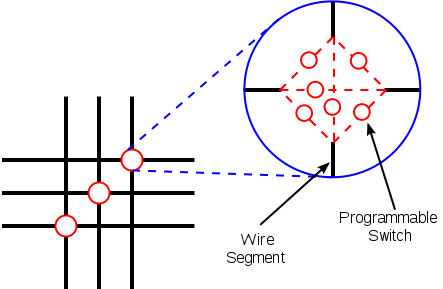 Схема коммутационной матрицы
На каждом пересечении проводников находится шесть переключающих ключей, управляемых своими ячейками конфигурационной памяти. Открывая одни и закрывая другие, можно обеспечить разную коммутацию сигналов между CLB.
CLB очень упрощенно состоит из блока, задающего булеву функцию от нескольких аргументов (она называется таблицей соответствия — Look Up Table, LUT) и триггера (flip-flop, FF). В современных FPGA LUT имеет шесть входов, но на рисунке для простоты показаны три. Выход LUT подается на выход CLB либо асинхронно (напрямую), либо синхронно (через триггер FF, работающий на системной тактовой частоте).
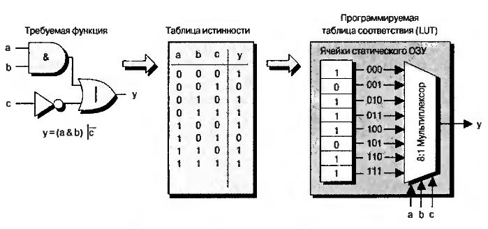 Принцип реализации LUT
Интересно посмотреть на принцип реализации LUT. Пусть у нас есть некоторая булева функция y = (a & b) |
c . Ее схемотехническое представление и таблица истинности показаны на рисунке. У функции три аргумента, поэтому она принимает 2^3 = 8 значений. Каждое из них соответствует своей комбинации входных сигналов. Эти значения вычисляются программой для разработки прошивки ПЛИС и записываются в специальные ячейки конфигурационной памяти.
Значение каждой из ячеек подается на свой вход выходного мультиплексора LUT, а входные аргументы булевой функции используются для выбора того или иного значения функции. CLB — важнейший аппаратный ресурс FPGA. Количество CLB в современных кристаллах FPGA может быть разным и зависит от типа и емкости кристалла. У Xilinx есть кристаллы с количеством CLB в пределах примерно от четырех тысяч до трех миллионов.
Помимо CLB, внутри FPGA есть еще ряд важных аппаратных ресурсов. Например, аппаратные блоки умножения с накоплением или блоки DSP. Каждый из них может делать операции умножения и сложения 18-битных чисел каждый такт. В топовых кристаллах количество блоков DSP может превышать 6000.
Другой ресурс — это блоки внутренней памяти (Block RAM, BRAM). Каждый блок может хранить 2 Кбайт. Полная емкость такой памяти в зависимости от кристалла может достигать от 20 Кбайт до 20 Мбайт. Как и CLB, BRAM и DSP-блоки связаны коммутационной матрицей и пронизывают весь кристалл. Связывая блоки CLB, DSP и BRAM, можно получать весьма эффективные схемы обработки данных.
Применение и преимущества FPGA
Первый чип FPGA, созданный Xilinx в 1985 году, содержал всего 64 CLB. В то время интеграция транзисторов на микросхемах была намного ниже, чем сейчас, и в цифровых устройствах часто использовались микросхемы «рассыпной логики». Были отдельно микросхемы регистров, счетчиков, мультиплексоров, умножителей. Под конкретное устройство создавалась своя печатная плата, на которой устанавливались эти микросхемы низкой интеграции.
Использование FPGA позволило отказаться от такого подхода. Даже FPGA на 64 CLB значительно экономит место на печатной плате, а доступность реконфигурации добавила возможность обновлять функциональность устройств уже после изготовления во время эксплуатации, как говорят «in the field» (отсюда и название — field-programmable gate array).
За счет того, что внутри FPGA можно создать любую аппаратную цифровую схему (главное, чтобы хватило ресурсов), одно из важных применений ПЛИС — это прототипирование микросхем ASIC.
Разработка ASIC очень сложна и затратна, цена ошибки очень высока, и вопрос тестирования логики критичен. Поэтому одним из этапов разработки еще до начала работы над физической топологией схемы стало ее прототипирование на одном или нескольких кристаллах FPGA.
Для разработки ASIC выпускают специальные платы, содержащие много FPGA, соединенных между собой. Прототип микросхемы работает на значительно меньших частотах (может быть, десятки мегагерц), но позволяет сэкономить на выявлении проблем и багов.
Однако, на мой взгляд, существуют более интересные применения ПЛИС. Гибкая структура FPGA позволяет реализовывать аппаратные схемы для высокоскоростной и параллельной обработки данных с возможностью изменить алгоритм.
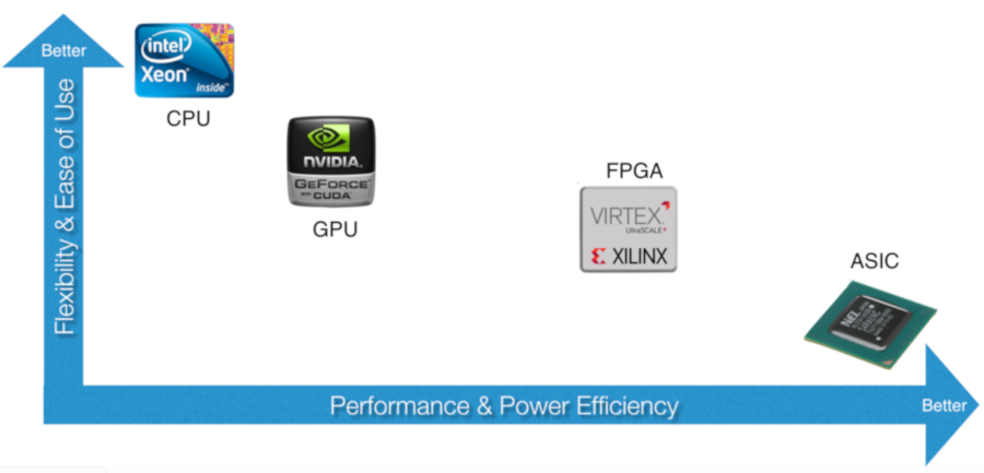 Сравнение аппаратных платформ
Давай подумаем, чем принципиально отличаются CPU, GPU, FPGA и ASIC. CPU универсален, на нем можно запустить любой алгоритм, он наиболее гибок, и использовать его легче всего благодаря огромному количеству языков программирования и сред разработки.
При этом из-за универсальности и последовательного выполнения инструкций CPU снижается производительность и повышается энергопотребление схемы. Происходит это потому, что на каждую полезную арифметическую операцию CPU совершает много дополнительных операций, связанных с чтением инструкций, перемещением данных между регистрами и кешем, и другие телодвижения.
На другой стороне находится ASIC. На этой платформе требуемый алгоритм реализуется аппаратно за счет прямого соединения транзисторов, все операции связаны только с выполнением алгоритма и нет никакой возможности изменить его. Отсюда максимальная производительность и наименьшее энергопотребление платформы. А вот перепрограммировать ASIC невозможно.
Справа от CPU находится GPU. Изначально эти микросхемы были разработаны для обработки графики, но сейчас используются и для майнинга вычислений общего назначения. Они состоят из тысяч небольших вычислительных ядер и выполняют параллельные операции над массивом данных.
Если алгоритм можно распараллелить, то на GPU получится добиться значительного ускорения по сравнению с CPU. С другой стороны, последовательные алгоритмы будут реализовываться хуже, поэтому платформа оказывается менее гибкой, чем CPU. Также для разработки под GPU надо иметь специальные навыки, знать OpenCL или CUDA.
Наконец, FPGA. Эта платформа сочетает эффективность ASIC с возможностью менять программу. ПЛИС не универсальны, но существует класс алгоритмов и задач, которые на них будут показывать лучшую производительность, чем на CPU и даже GPU. Сложность разработки под FPGA выше, однако новые средства разработки делают этот разрыв меньше.
Решающее же преимущество FPGA — это способность обрабатывать данные в темпе их поступления с минимальной задержкой реакции. В качестве примера можешь вообразить умный сетевой маршрутизатор с большим количеством портов: при поступлении пакета Ethernet на один из его портов необходимо проверить множество правил, прежде чем выбрать выходной порт. Возможно, потребуется изменение некоторых полей пакета или добавление новых.
Использование FPGA позволяет решать эту задачу мгновенно: байты пакета еще только начали поступать в микросхему из сетевого интерфейса, а его заголовок уже анализируется. Использование процессоров тут может существенно замедлить скорость обработки сетевого трафика. Ясно, что для маршрутизаторов можно сделать заказную микросхему ASIC, которая будет работать наиболее эффективно, но что, если правила обработки пакетов должны меняться? Достичь требуемой гибкости в сочетании с высокой производительностью поможет только FPGA.
Таким образом, FPGA используются там, где нужна высокая производительность обработки данных, наименьшее время реакции, а также низкое энергопотребление.
FPGA in the cloud
В облачных вычислениях FPGA применяются для быстрого счета, ускорения сетевого трафика и осуществления доступа к массивам данных. Сюда же можно отнести использование FPGA для высокочастотной торговли на биржах. В серверы вставляются платы FPGA с PCI Express и оптическим сетевым интерфейсом производства Intel (Altera) или Xilinx.
На FPGA отлично ложатся криптографические алгоритмы, сравнение последовательностей ДНК и научные задачи вроде молекулярной динамики. В Microsoft давно используют FPGA для ускорения поискового сервиса Bing, а также для организации Software Defined Networking внутри облака Azure.
Бум машинного обучения тоже не обошел стороной FPGA. Компании Xilinx и Intel предлагают средства на основе FPGA для работы с глубокими нейросетями. Они позволяют получать прошивки FPGA, которые реализуют ту или иную сеть напрямую из фреймворков вроде Caffe и TensorFlow.
Причем это все можно попробовать, не выходя из дома и используя облачные сервисы. Например, в Amazon можно арендовать виртуальную машину с доступом к плате FPGA и любым средствам разработки, в том числе и machine learning.
FPGA on the edge
Что еще интересное делают на FPGA? Да чего только не делают! Робототехника, беспилотные автомобили, дроны, научные приборы, медицинская техника, пользовательские мобильные устройства, умные камеры видеонаблюдения и так далее.
Традиционно FPGA применялись для цифровой обработки одномерных сигналов (и конкурировали с процессорами DSP) в устройствах радиолокации, приемопередатчиках радиосигналов. С ростом интеграции микросхем и увеличением производительности платформы FPGA стали все больше применяться для высокопроизводительных вычислений, например для обработки двумерных сигналов «на краю облака» (edge computing).
Эту концепцию легче всего понять на примере видеокамеры для анализа автомобильного трафика с функцией распознавания номеров машин. Можно взять камеру с возможностью передачи видео через Ethernet и обрабатывать поток на удаленном сервере. С ростом числа камер будет расти и нагрузка на сеть, что может привести к сбоям системы.
Вместо этого лучше реализовать распознавание номеров на вычислителе, установленном прямо в корпус видеокамеры, и передавать в облако номера машин в формате текста. Для этого даже можно взять сравнительно недорогие FPGA с низким энергопотреблением, чтобы обойтись аккумулятором. При этом остается возможность изменять логику работы FPGA, например, при изменении стандарта автомобильных номеров.
Что до робототехники и дронов, то в этой сфере как раз особенно важно выполнять два условия — высокая производительность и низкое энергопотребление. Платформа FPGA подходит как нельзя лучше и может использоваться, в частности, для создания полетных контроллеров для беспилотников. Уже сейчас делают БПЛА, которые могут принимать решения на лету.
Как разрабатывать проект на FPGA?
Существуют разные уровни проектирования: низкий, блочный и высокий. Низкий уровень предполагает использование языков типа Verilog или VHDL, на которых ты управляешь разработкой на уровне регистровых передач (RTL — register transfer level). В этом случае ты формируешь регистры, как в процессоре, и определяешь логические функции, изменяющие данные между ними.
Схемы FPGA всегда работают на определенных тактовых частотах (обычно 100–300 МГц), и на уровне RTL ты определяешь поведение схемы с точностью до такта системной частоты. Эта кропотливая работа приводит к созданию максимально эффективных схем с точки зрения производительности, потребления ресурсов кристалла FPGA и энергопотребления. Но тут требуются серьезные скиллы в схемотехнике, да и с ними процесс небыстрый.
На блочном уровне ты занимаешься в основном соединением уже готовых крупных блоков, которые выполняют определенные функции, для получения нужной тебе функциональности системы на кристалле (system-on-chip).
На высоком уровне проектирования ты уже не будешь контролировать данные на каждом такте, вместо этого сконцентрируешься на алгоритме. Существуют компиляторы или трансляторы с языков C и C++ на уровень RTL, например Vivado HLS. Он довольно умный и позволяет транслировать на аппаратный уровень широкий класс алгоритмов.
Главное преимущество такого подхода перед языками RTL — ускорение разработки и особенно тестирования алгоритма: код на C++ можно запустить и верифицировать на компьютере, и это будет намного быстрее, чем тестировать изменения алгоритма на уровне RTL. За удобство, конечно, придется заплатить — схема может получиться не такой быстрой и займет больше аппаратных ресурсов.
Часто мы готовы платить эту цену: если грамотно использовать транслятор, то эффективность не сильно пострадает, а ресурсов в современных FPGA достаточно. В нашем мире с критичным показателем time to market это оказывается оправданным.
Часто в одном дизайне нужно совместить все три стиля разработки. Допустим, нам нужно сделать устройство, которое мы могли бы встроить в робота и наделить его способностью распознавать объекты в видеопотоке — например, дорожные знаки. Возьмем микросхему видеосенсора и подключим ее напрямую к FPGA. Для отладки можем использовать монитор HDMI, тоже подключенный к FPGA.
Кадры с камеры будут передаваться в FPGA по интерфейсу, который заведомо определен производителем сенсора (USB тут не катит), обрабатываться и выводиться на монитор. Для обработки кадров понадобится фреймбуфер, который обычно находится во внешней памяти DDR, установленной на печатной плате рядом с микросхемой FPGA.
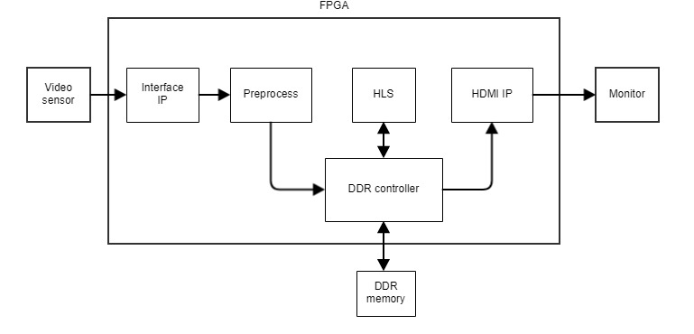 Типичная блок-схема проекта FPGA
Если производитель видеосенсора не предоставляет Interface IP для нашей микросхемы FPGA, то нам придется писать его самостоятельно на языке RTL, считая такты, биты и байты в соответствии со спецификацией протокола передачи данных. Блоки Preprocess, DDR Controller и HDMI IP мы, скорее всего, возьмем готовые и просто соединим их интерфейсы. А блок HLS, который выполняет поиск и обработку поступающих данных, мы можем написать на C++ и транслировать при помощи Vivado HLS.
Скорее всего, нам еще потребуется какая-то готовая библиотека детектора и классификатора дорожных знаков, адаптированная для использования в FPGA. В этом примере я, конечно, привожу сильно упрощенную блок-схему дизайна, но логику работы она отражает корректно.
Рассмотрим путь проектирования от написания кода RTL до получения конфигурационного файла для загрузки в FPGA.
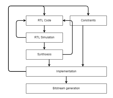 Путь проектирования
Итак, ты пишешь код RTL, который реализует нужную тебе схему. Прежде чем его проверять на реальном железе, надо убедиться, что он верный и корректно решает требуемую задачу. Для этого используется RTL-моделирование в симуляторе на компьютере.
Ты берешь свою схему, представленную пока только в коде RTL, и помещаешь ее на виртуальный стенд, где подаешь последовательности цифровых сигналов на входы схемы, регистрируешь выходные диаграммы, зависимости от времени выходных сигналов и сравниваешь с ожидаемыми результатами. Обычно ты находишь ошибки и возвращаешься к написанию RTL.
Далее логически верифицированный код подается на вход программе-синтезатору. Она преобразует текстовое описание схемы в связанный список цифровых элементов из библиотеки, доступной для данного кристалла FPGA. В этом списке будут отображены такие элементы, как LUT, триггеры, и связи между ними. На этой стадии элементы пока никак не привязаны к конкретным аппаратным ресурсам. Чтобы это сделать, требуется наложить на схему ограничения (Constraints) — в частности, указать, с какими физическими контактами ввода-вывода микросхемы FPGA связаны логические входы и выходы твоей схемы.
В этих ограничениях также требуется указать, на каких тактовых частотах должна работать схема. Выход синтезатора и файл ограничений отдаются процессору Implementation, который, помимо прочего, занимается размещением и трассировкой (Place and Route).
Процесс Place каждый пока еще обезличенный элемент из netlist привязывает к конкретному элементу внутри микросхемы FPGA. Далее начинает работу процесс Route, который пытается найти оптимальное соединение этих элементов для соответствующей конфигурации коммутационной матрицы ПЛИС.
Place и Route действуют, исходя из ограничений, наложенных нами на схему: контактами ввода-вывода и тактовой частотой. Период тактовой частоты очень сильно влияет на Implementation: он не должен быть меньше, чем временная задержка на логических элементах в критической цепи между двумя последовательными триггерами.
Часто сразу удовлетворить это требование не удается, и тогда надо вернуться на начальный этап и изменить код RTL: например, попытаться сократить логику в критической цепи. После успешного завершения Implementation нам известно, какие элементы где находятся и как они связаны.
Только после этого запускается процесс создания бинарного файла прошивки FPGA. Остается его загрузить в реальное железо и проверить, работает ли оно так, как ожидалось. Если на этом этапе возникают проблемы, значит, моделирование было неполным и на этом этапе не были устранены все ошибки и недочеты.
Можно вернуться на стадию симуляции и смоделировать нештатную ситуацию, а если и это не сработает, на крайний случай предусмотрен механизм отладки непосредственно в работающем железе. Ты можешь указать, какие сигналы хочешь отслеживать во времени, и среда разработки сгенерирует дополнительную схему логического анализатора, которая размещается на кристалле рядом с твоей разрабатываемой схемой, подключается к интересующим тебя сигналам и сохраняет их значения во времени. Сохраненные временные диаграммы нужных сигналов можно выгрузить на компьютер и проанализировать.
Существуют и высокоуровневые средства разработки (HLS, High-level synthesis), и даже готовые фреймворки для создания нейросетей в ПЛИС. Эти средства на выходе генерят код RTL на языках VHDL или Verilog, который дальше спускается по цепочке Synthesis → Implementation → Bitstream generation. Ими вполне можно пользоваться, но, чтобы использовать их эффективно, надо иметь хотя бы минимальное представление о языках уровня RTL.
Продолжение следует
Надеюсь, теория тебя не слишком загрузила! В следующей статье я расскажу о практике: мы посмотрим, что конкретно нужно делать, чтобы запрограммировать FPGA.
Источник