![]()
- Engine
- Licenses
- Forum
- Blog
- Downloads
- Wiki
- Reference
- Login

- Login
-
EN

-
#1, by smac96Tuesday, 16. January 2018, 11:00 5 years ago
Hi,
What could be the problem if the game doesn’t start at all and the stderr.txt file containt this: «libpng error: IHDR: CRC error»?
Thanks for any help!
(Win 10 64 bit, Visionaire 3.7)
smac96
Newbie
97 Posts
-
#2, by sebastianTuesday, 16. January 2018, 12:16 5 years ago
I know this error from another software…
mostly caused by invalid png images (color profile and such stuff)
In case of VS im not sure though
sebastian
Thread Captain
2346 Posts
-
#3, by smac96Tuesday, 16. January 2018, 12:23 5 years ago
Maybe not a Visionaire error but instehad a conflict with another software or hardware component?
smac96
Newbie
97 Posts
-
#4, by SimonSTuesday, 16. January 2018, 12:40 5 years ago
Visionaire 3.7 has a very old libpng, so you need to set the generated pngs to maximum compatibility.
Pngs have a format with header part, that has a checksum, if that doesn’t match, there are errors, it’s also possible that the png is a newer standard and the libpng doesn’t understand them.
SimonS
Thread Captain
1554 Posts
-
#5, by smac96Tuesday, 16. January 2018, 12:47 5 years ago
Visionaire 3.7 has a very old libpng, so you need to set the generated pngs to maximum compatibility.
Pngs have a format with header part, that has a checksum, if that doesn’t match, there are errors, it’s also possible that the png is a newer standard and the libpng doesn’t understand them.
Thanks SimonS!
smac96
Newbie
97 Posts
-
#6, by smac96Tuesday, 16. January 2018, 12:53 5 years ago
Do you know why only one player so far had this issue but others don’t?
smac96
Newbie
97 Posts
-
#7, by SimonSTuesday, 16. January 2018, 12:57 5 years ago
Maybe the files are corrupted while downloading. Steam has an option to check the files.
SimonS
Thread Captain
1554 Posts
-
#8, by smac96Tuesday, 16. January 2018, 13:22 5 years ago
Maybe the files are corrupted while downloading. Steam has an option to check the files.
Thanks!
smac96
Newbie
97 Posts
-
#9, by LebosteinTuesday, 23. January 2018, 12:57 5 years ago
@smac (Stefano Maccarinelli?): Have you considered an update to Visionaire 4? Visionaire 3.x was very sluggish, memory-hungry, error-prone and has very long load and save times. And it is from 2012 and problems with current operating systems like Windows 10 are possible. Visionaire 4 was rewritten and it runs much faster and more powerful than Visionaire 3.x.
Lebostein
Key Killer
620 Posts
-
#10, by smac96Tuesday, 23. January 2018, 13:11 5 years ago
@smac (Stefano Maccarinelli?): Have you considered an update to Visionaire 4? Visionaire 3.x was very sluggish, memory-hungry, error-prone and has very long load and save times. And it is from 2012 and problems with current operating systems like Windows 10 are possible. Visionaire 4 was rewritten and it runs much faster and more powerful than Visionaire 3.x.
Hi! Yes. We considered it and we probably do it. We already bought the license. It will of course take a lot of time to re-test everything because the game is huge but the main problem is that using a newer version of Visionaire will make the current savegames incompatible. If it’s not a problem for the players I think it will be ok to do it.
There are hundreds of people that played/are playing the game and right now only very few of them directly reported us major problems. Unfortunately one of the players that had big issues playing was a reviewer of an important website for point and click lovers and the note she gave us really hurts a lot! Of course she had the full right to write what happened to her and let other players know that they might have problems too. This is important for us. Luckily the majority of reviews are positive and we’re very happy about it! Anyway, after so many years of hard work and huge sacrifices for a 2-person studio it’s very sad and frustrating to receive critics mostly because of the old buggy 3.7 game engine
smac96
Newbie
97 Posts
-
#11, by smac96Tuesday, 23. January 2018, 15:04 5 years ago
After some tests with version 4.2.5… I think we could update the game sooner as expected and let the players decide which version play
smac96
Newbie
97 Posts


- 1
- 2
- 3
Доброго времени суток!
Вам когда-нибудь хотелось узнать как устроены файлы PNG? Нет? А я все равно расскажу.
Формат PNG(Portable Network Graphics) был изобретен в 1995 году, чтобы стать заменой GIF, а уже в 1996, с выходом версии 1.0, он был рекомендован W3C, в качестве полноправного сетевого формата. На сегодняшний день PNG является одним из основных форматов веб-графики.
Под катом вы найдете общее описание строения PNG-файла, некоторое количество картинок-схем, препарирование  в hex-редакторе, и, конечно, ссылку на спецификацию.
Общее строение
Структура PNG в самом общем виде представлена на следующем рисунке.
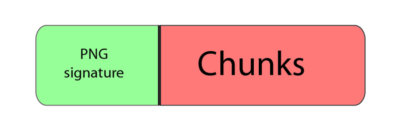
То есть файл состоит из подписи и некоторого количества блоков(чанков, chunks), каждый из которых несет в себе некоторую информацию (спасибо КО!). Но почему подпись нельзя считать одним из чанков? Давайте разберемся поподробнее.
Подпись файла
Подпись PNG-файла всегда одинакова, состоит из 8 байт, и представляет собой (в hex-записи)
89 50 4E 47 0D 0A 1A 0A
Что же это означает?
- 89 — non-ASCII символ. Препятствует распознаванию PNG, как текстового файла, и наоборот.
- 50 4E 47 — PNG в ASCII записи.
- 0D 0A — CRLF (Carriage-return, Line-feed), DOS-style перевод строки.
- 1A — останавливает вывод файла в DOS режиме (end-of-file), чтобы вам не вываливалось многокилобайтное изображение в текстовом виде.
- 0A — LF, Unix-style перевод строки.
Chunks
Чанки — это блоки данных, из которых состоит файл. Каждый чанк состоит из 4 секций.
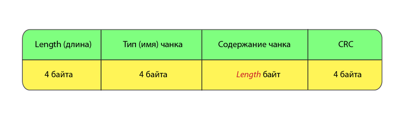
Разберем эти секции по порядку.
Длина
Ну, с длиной вроде все ясно. Просто числовое значение длины блока данных.
Тип (имя)
С типом немного поинтересней. Тип представляет собой 4 чувствительных к регистру ASCII-символа. Регистры символов (пятый бит в числовой записи символа) в имени чанка различаются неспроста — это флаги, которые сообщают декодеру некоторую дополнительную информацию.
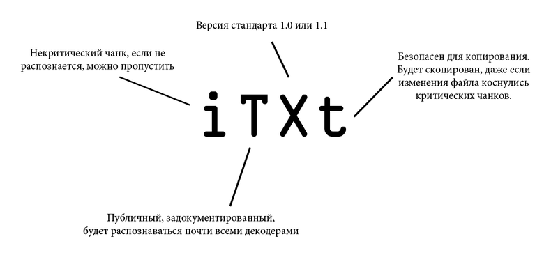
- Регистр первого символа определяет является ли данный чанк критическим(верхний регистр) или вспомогательным(нижний регистр). Критические чанки должны распознаваться каждым декодером. Если декодер встречает критический чанк, тип которого не может распознать, он обязан завершить выполнение с ошибкой.
- Регистр второго символа задает «публичность»(верхний регистр) или «приватность»(нижний регистр) чанка. «Публичные» чанки — официальные, задокументированные, распознаваемые большинством декодеров. Но если вдруг вам для каких-то своих нужд понадобится кодировать специфическую информацию, то просто в имени чанка сделайте второй символ маленьким.
- Регистр третьего символа оставлен для будущих свершений. Предполагается, что он будет использоваться для дифференциации различных версий стандарта. Для версий 1.0 и 1.1 третий символ должен быть большим. Если он (внезапно!) оказался маленьким, все нынешние декодеры должны поступать с чанком, так же как и с любым другим не распознанным (то есть выходить с ошибкой если чанк критический, или пропускать в противном случае).
- Регистр же четвертого символа означает возможность копирования данного чанка редакторами, которые не могут его распознать. Если регистр нижний, чанк может быть скопирован, вне зависимости от степени модификации файла, иначе (верхний регистр) он копируется только в случае, когда при модификации не были затронуты никакие критические чанки.
Для лучшего понимания, давайте разберем флаги на примере чанка, содержащего текст.
Ниже приведен список типов чанков с краткими пояснениями.
Критические чанки
- IHDR — заголовок файла, содержит основную информацию о изображении. Обязан быть первым чанком.
- PLTE — палитра, список цветов.
- IDAT — содержит, собственно, изображение. Рисунок можно разбить на несколько IDAT чанков, для потоковой передачи. В каждом файле должен быть хотя бы один IDAT чанк.
- IEND — завершающий чанк, обязан быть последним в файле.
Вспомогательные чанки
- bKGD — этот чанк задает основной фоновый цвет.
- cHRM используется для задания CIE 1931 цветового пространства.
- gAMA — определяет гамму.
- hIST — в этом чанке может храниться гистограмма или общее содержание каждого цвета в изображении.
- iCCP — цветовой профиль ICC
- iTXt — содержит текст в UTF-8, возможно сжатый, с необязательной языковой меткой. iTXt чанк с ключевым словом ‘XML:com.adobe.xmp’ может содержать Extensible Metadata Platform (XMP).
- pHYs — содержит предполагаемый размер пикселя и/или отношение сторон изображения.
- sBIT (significant bits) — определяет «цветовую точность» (color-accuracy) изображения (черно-белое, полный цвет, черно-белое с прозрачностью и т.д.), для более простого декодирования.
- sPLT — предлагает палитру для использования, если полный спектр цветов недоступен.
- sRGB — свидетельствует о использовании стандартной sRGB схемы.
- sTER — индикатор стереоскопических изображений.
- tEXt — может содержать текст в ISO/IEC 8859-1 формате, с одной name=value парой для каждого чанка.
- tIME — хранит дату последнего изменения изображения.
- tRNS — содержит информацию о прозрачности.
- zTXt — сжатый текст, с теми же ограничениям, что и tEXt.
Более подробную информацию можно найти в спецификации.
CRC
Контрольная сумма CRC-32. Кстати на днях был топик о ее подсчете в Windows.
Минимальный PNG
С общей структурой разобрались. Теперь разберем содержание обязательных чанков. Но какие из них обязательные (не критические, критические обязаны распознаваться декодером, а не присутствовать в каждом файле), и как выглядит минимальный PNG-файл? А вот как:

IHDR
Блок данных в IHDR содержит следующие поля:
- Ширина, 4 байта
- Высота, 4 байта
- Битовая глубина (bit depth), определяет количество бит на каждый сэмпл(не пиксель), 1 байт
- Тип цвета, состоит из 3 флагов 1 (используется палитра), 2 (используется цвет, не монохромное изображение), and 4 (присутствует альфа-канал), 1 байт
- Метод сжатия. На данный момент доступно только значение 0 — сжатие по алгоритму deflate. Если значение отлично от 0, чанк считается нераспознанным, и декодер рапортует об ошибке. 1 байт
- Метод фильтрации. Так же, как и в случае сжатия, на данный момент может быть только нулем. 1 байт
- Interlace(переплетение) метод. Определяет порядок передачи данных. На данный момент доступно 2 значения: 0 (no interlace) и 1 (Adam7 interlace). 1 байт
Adam7 interlacing прекрасно демонстрирует картинка из википедии (да-да, GIF в статье про PNG):

IEND
Сигнализирует о конце файла, блок данных этого чанка не содержит ничего.
IDAT
Содержит данные, закодированные, в соответствии с полем метода сжатия в заголовке. Алгоритм декодирования выходит за рамки данной статьи (однако если будут желающие, может появиться в следующей), но в довольно хорошо (и по-русски) описан здесь.
Таким образом, простейший PNG-файл (на примере ) выглядит следующим образом.

Заключение
При написании данной статьи я ставил своей задачей дать читателю общие знания о строении PNG-файла, для более глубокого понимания рекомендуется читать спецификации.
Топик на хабре про строение JPEG: habrahabr.ru/blogs/algorithm/102521
Топик на хабре про строение GIF: habrahabr.ru/blogs/algorithm/127083
Спасибо за внимание, буду рад любой критике!
File Structure
For a PNG file, the header is always represented by fixed bytes, and the remaining parts consist of three or more chunks of PNG data in a specific order.
File header: 89 50 4E 47 0D 0A 1A 0A + chunk + chunk + chunk…
Chunks
PNG contains two types of chunks: one called critical chunks that are the standard chunks, another called ancillary chunks that are optional. Critical chunks define four standard chucks that must be included in every PNG file, and a PNG reader must support these blocks.
| Chunk Characters | Chunk Name | Multiple Chucks | Optional | Position Limitation |
|---|---|---|---|---|
| IHDR | Image Header | False | False | First Chunk |
| cHRM | Primary Chromaticities and White Point | False | True | Before PLTE and IDAT |
| gAMA | Image Gamma | False | True | Before PLTE and IDAT |
| sBIT | Significant Bits | False | True | Before PLTE and IDAT |
| PLTE | Palette | False | True | Before IDAT |
| bKGD | Background Color | False | True | Before PLTE and IDAT |
| hIST | Image Histogram | False | True | Before PLTE and IDAT |
| tRNS | Transparency | False | True | Before PLTE and IDAT |
| oFFs | Image Offset | False | True | Before IDAT |
| pHYs | Physical Pixel Dimensions | False | True | Before IDAT |
| sCAL | Physical Scale | False | True | Before IDAT |
| IDAT | Image Data | True | False | Consecutive with Other IDATs |
| tIME | Image Last Modification Time | False | True | No limit |
| tEXt | Textual Data | True | True | No limit |
| zTXt | Compressed Textual Data | True | True | No limit |
| fRAc | Fractal Parameters | True | True | No limit |
| gIFg | GIF Conversion Info | True | True | No limit |
| gIFt | GIF Plain Text | True | True | No limit |
| gIFx | GIF Conversion Info | True | True | No limit |
| IEND | Image Trailer | False | False | End of PNG Data Stream |
There is a unified structure for each chunk, and each chunk is composed of four parts:
| Name | Length in Bytes | Description |
|---|---|---|
| Length | 4 Bytes | Specifies the length of the data field in the chunk, which does not exceed (231-1) bytes |
| Chunk Type Code | 4 Bytes | Consists of ASCII letters (A-Z and A-Z) |
| Chunk Data | length Varies | Stores the data specified by the Chunk Type Code |
| CRC | 4 Bytes | Stores the Cyclic Redundancy Check information |
CRC(Cyclic Redundancy Check)value is calculated based on the Chunk Type Code and Chunk Data.
For more details, see PNG Chunks
IHDR
IHDR (Image Header Chunk): It stores basic image information, 13-bytes long, must be the first chunk in a PNG data stream, and there must be only one file header chunk in a PNG data stream.
| Name | Number of Bytes | Description |
|---|---|---|
| Width | 4 bytes | Image width (in pixels) |
| Height | 4 bytes | Image height (in pixels) |
We often change the height or width of an image to corrupt it to hide information.
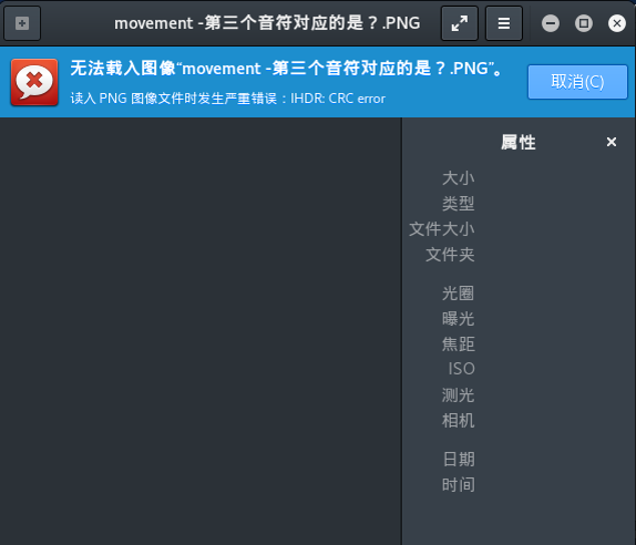
You can see here Kali won’t open the image, showing the IHDR CRC error. This is a sign that the IHDR chunk was modified.
You might be able to restore the corrupted image by changing the image’s width and length, or file header back to the correct values.
CTF Example
WDCTF-finals-2017
Download the challenge here
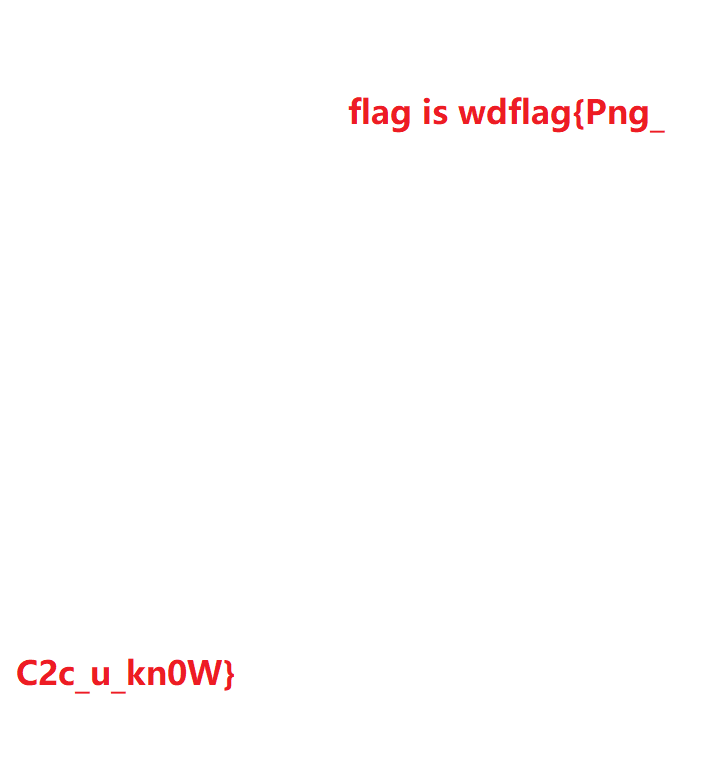
If you look at the file, you can see that the header and width of the PNG file are incorrect.
00000000  80 59 4e 47 0d 0a 1a 0a  00 00 00 0d 49 48 44 52  |.YNG........IHDR|
00000010  00 00 00 00 00 00 02 f8  08 06 00 00 00 93 2f 8a  |............../.|
00000020  6b 00 00 00 04 67 41 4d  41 00 00 9c 40 20 0d e4  |[email protected] ..|
00000030  cb 00 00 00 20 63 48 52  4d 00 00 87 0f 00 00 8c  |.... cHRM.......|
00000040  0f 00 00 fd 52 00 00 81  40 00 00 7d 79 00 00 e9  |[email protected]}y...|
...
Note that you can’t just randomly change the image’s width, you need to brute force the width based on the IHDR chunk’s CRC value (see Python script below).
import os
import binascii
import struct

misc = open("misc4.png","rb").read()

for i in range(1024):
    data = misc[12:16] + struct.pack('>i',i)+ misc[20:29]
    crc32 = binascii.crc32(data) & 0xffffffff
    if crc32 == 0x932f8a6b:
        print(i)
The script returned 709, so changing the image’s width to 709 will restore the image and get you the flag.
PLTE
PLTE (Palette Chunk): It contains from 1 to 256 palette entries, each a three-byte series of the form.
— Red: 1 byte (0 = black, 255 = red)
— Green: 1 byte (0 = black, 255 = green)
— Blue: 1 byte (0 = black, 255 = blue)
IDAT
IDAT (Image Data Chunk): It stores the actual image data which contains multiple image chucks in the data stream.
— Stores image data
— Contains multiple image chucks in the data stream
— Uses a derivative of LZ77 algorithm to perform compression
— Uses zlib to perform decompression
Note that IDAT will only continue to a new chunk when the previous chunk is full.
CTF Example
sctf 2014 — misc
Use pngcheck display information about the PNG file
Download the challenge here
.pngcheck.exe -v sctf.png
File: sctf.png (1421461 bytes)
  chunk IHDR at offset 0x0000c, length 13
    1000 x 562 image, 32-bit RGB+alpha, non-interlaced
  chunk sRGB at offset 0x00025, length 1
    rendering intent = perceptual
  chunk gAMA at offset 0x00032, length 4: 0.45455
  chunk pHYs at offset 0x00042, length 9: 3780x3780 pixels/meter (96 dpi)
  chunk IDAT at offset 0x00057, length 65445
    zlib: deflated, 32K window, fast compression
  chunk IDAT at offset 0x10008, length 65524
...
  chunk IDAT at offset 0x150008, length 45027
  chunk IDAT at offset 0x15aff7, length 138
  chunk IEND at offset 0x15b08d, length 0
No errors detected in sctf.png (28 chunks, 36.8% compression).
We can see when the first IDAT is full (length 65524), it continued to the second IDAT. Now, we know the length for a full IDAT. Try to compare the last two IDAT (offset 0x150008 and 0x15aff7 ), do you see anything strange?
The second to last IDAT length is 45027 and the last IDAT length is 138.
Clearly, something is wrong with the last IDAT because the second to last IDAT is not full.
Use python and zlib to decompress the content of the last IDAT. Note that length, chunk type, and CRC check value at the end are excluded.
import zlib
import binascii
IDAT = "789...667".decode('hex')
result = binascii.hexlify(zlib.decompress(IDAT))
print result
IEND
IEND (Image Trailer Chunk): It is used to mark the end of a PNG data stream or file, and it must be placed at the end of the file.
Example
- IEND’s chunk length is always
00 00 00 00 - IEND’s chunk type is always IEND
49 45 4E 44 - IEND’S CRC value is always
AE 42 60 82
That means a PNG file will always end with these bytes:
00 00 00 00 49 45 4E 44 AE 42 60 82
LSB
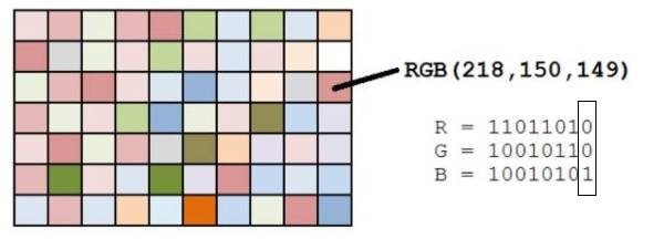
LSB stands for Least Significant Bit. Each pixel in a PNG image is generally composed of RGB three primary colors (red, green, and blue), each color occupies 8 bits, and the value range is from ‘0x00’ to ‘0xFF’, so there are 256 colors. The total number of colors is equal to 256 to the third power or 16777216.
The human eye can distinguish about 10 million different colors, which means the human eye cannot distinguish the remaining 6,777,216 colors.
LSB steganography is to modify the Least Significant Bit of each color, containing 8 bits, in an RGB value.
If you want to find informing hidden using LSB, you can use this tool Stegsolve to perform analysis.
Use the buttons at the bottom of Stegsolve to see information extracted from each color channel.
In the following image, we found the hidden information by checking LSB on the red channel:
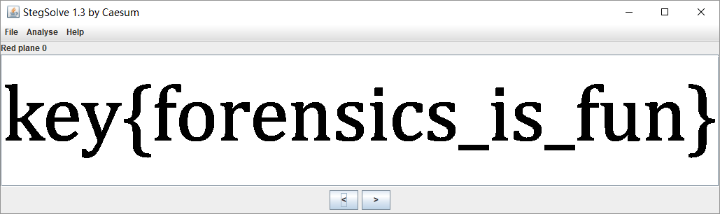
With the help of StegSolve, you can find hidden information by checking LSB each color channel.
CTF Example
HCTF 2016 — pic again
Download the challenge here
There is information hidden in the LSB of the RGB colors. Use Stegsolve-->Analyse-->Data Extract to extract it.
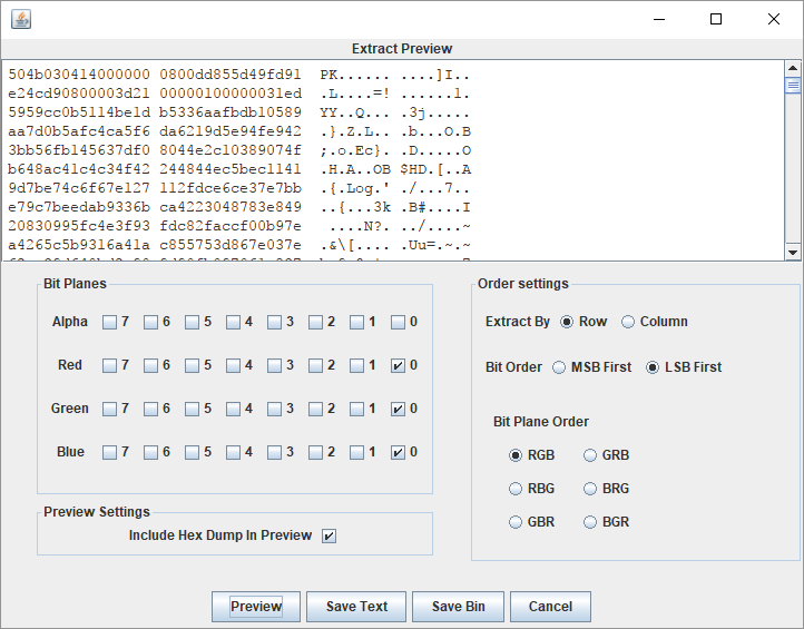
We can see zip file header, use save bin to save the zip file, and run the ELF executable to obtain the flag.
本页面的全部内容在 CC BY-NC-SA 4.0 协议之条款下提供,附加条款亦可能应用。
Abstract
This document describes PNG (Portable Network Graphics), an extensible file format for the lossless, portable, well-compressed storage of static and animated raster images. PNG provides a patent-free replacement for GIF and can also replace many common uses of TIFF. Indexed-colour, greyscale, and truecolour images are supported, plus an optional alpha channel. Sample depths range from 1 to 16 bits.
PNG is designed to work well in online viewing applications, such as the World Wide Web, so it is fully streamable with a progressive display option. PNG is robust, providing both full file integrity checking and simple detection of common transmission errors. Also, PNG can store colour space data for improved colour matching on heterogeneous platforms.
This specification defines two Internet Media Types, image/png and image/apng.
Status of This Document
This section describes the status of this
document at the time of its publication. A list of current W3C
publications and the latest revision of this technical report can be found
in the W3C technical reports index at
https://www.w3.org/TR/.
This specification is intended to become
an International Standard,
but is not yet one.
It is inappropriate to refer to this specification
as an International Standard.
This document was published by the Portable Network Graphics (PNG) Working Group as
a First Public Working Draft using the
Recommendation track.
Publication as a First Public Working Draft does not
imply endorsement by W3C and its Members.
This is a draft document and may be updated, replaced or obsoleted by other
documents at any time. It is inappropriate to cite this document as other
than work in progress.
This document was produced by a group
operating under the
W3C Patent
Policy.
W3C maintains a
public list of any patent disclosures
made in connection with the deliverables of
the group; that page also includes
instructions for disclosing a patent. An individual who has actual
knowledge of a patent which the individual believes contains
Essential Claim(s)
must disclose the information in accordance with
section 6 of the W3C Patent Policy.
This document is governed by the
2 November 2021 W3C Process Document.
The design goals for this specification were:
- Portability: encoding, decoding, and transmission should be
software and hardware platform independent. - Completeness: it should be possible to represent truecolour,
indexed-colour, and greyscale images, in each case with the
option of transparency, colour space information, and ancillary
information such as textual comments. - Serial encode and decode: it should be possible for
datastreams to be generated serially and read serially, allowing
the datastream format to be used for on-the-fly generation and
display of images across a serial communication channel. - Progressive presentation: it should be possible to transmit
datastreams so that an approximation of the whole image can be
presented initially, and progressively enhanced as the datastream
is received. - Robustness to transmission errors: it should be possible to
detect datastream transmission errors reliably. - Losslessness: filtering and compression should preserve all
information. - Performance: any filtering, compression, and progressive
image presentation should be aimed at efficient decoding and
presentation. Fast encoding is a less important goal than fast
decoding. Decoding speed may be achieved at the expense of
encoding speed. - Compression: images should be compressed effectively,
consistent with the other design goals. - Simplicity: developers should be able to implement the
standard easily. - Interchangeability: any standard-conforming PNG decoder shall
be capable of reading all conforming PNG datastreams. - Flexibility: future extensions and private additions should
be allowed for without compromising the interchangeability of
standard PNG datastreams. - Freedom from legal restrictions: no algorithms should be used
that are not freely available.
This specification specifies a datastream and an
associated file format, Portable Network Graphics (PNG,
pronounced «ping»), for a lossless, portable, compressed
individual computer graphics image
or frame-based animation,
transmitted across the
Internet. Indexed-colour, greyscale, and truecolour images are
supported, with optional transparency. Sample depths range from 1
to 16 bits. PNG is fully streamable with a progressive display
option. It is robust, providing both full file integrity checking
and simple detection of common transmission errors. PNG can store
gamma value and chromaticity data as well as a full ICC colour profile
or CICP image format signaling metadata,
for accurate colour matching on heterogenous platforms. This
Standard defines the Internet Media types «image/png»
and «image/apng». The
datastream and associated file format have value outside of the
main design goal.
For the purposes of this specification the following
definitions apply.
- alpha
- a value representing a pixel degree of opacity. The more
opaque a pixel, the more it hides the background against which
the image is presented. Zero alpha represents a completely
transparent pixel, maximum alpha represents a completely opaque
pixel. - alpha compaction
- an implicit representation of transparent
pixels. If every
pixel with a specific colour or greyscale value is fully
transparent and all other pixels are fully opaque, the
alpha
channel may be
represented implicitly. - alpha separation
- separating an alpha channel in which every
pixel is fully
opaque; all alpha values are the maximum value.
The fact that all pixels are fully opaque is represented implicitly. - alpha table
- indexed table of alpha sample values, which in an indexed-colour image defines the alpha
sample values of the reference image. The alpha table has the
same number of entries as the palette. - ancillary chunk
- class of chunk that provides additional
information. A PNG decoder, without processing an
ancillary chunk, can still produce a meaningful image, though not
necessarily the best possible image. - animated image
- Optional animation, consisting of a series of frames.
The first frame may be,
but need not be,
the static image. - bit depth
- for indexed-colour images, the number of bits
per palette index. For other images, the
number of bits per sample in the image. This is the value
that appears in the
11.2.1 IHDR Image
header chunk. - byte
- 8 bits; also called an octet. The highest bit (value 128) of
a byte is numbered bit 7; the lowest bit (value 1) is numbered
bit 0.
It represents an unsigned integer limited to the range 0 to
28-1. - byte order
- ordering of bytes for multi-byte data values within a
PNG file
or PNG datastream. PNG uses
network byte order. - canvas
- the area on the output device on which the frames are to be displayed.
The contents of the canvas are not necessarily available to the decoder.
If a bKGD chunk exists,
it may be used to fill the canvas if there is no preferable background - channel
- array of all per-pixel information of a particular kind
within a reference image. There are five kinds of
information: red, green, blue, greyscale, and alpha. For example the alpha
channel is the array of alpha values within a reference
image. - chromaticity
- pair of CIE x,y values [COLORIMETRY] that precisely specify a colour,
except for the brightness information. - chunk
- section of a PNG datastream. Each chunk has a chunk
type. Most chunks also include data. The format and meaning of
the data within the chunk are determined by the chunk type.
Each chunk is either a
critical chunk or an
ancillary chunk. - composite (verb)
- to form an image by merging a foreground image and a
background image, using transparency information to determine
where and to what extent the background should be visible. The
foreground image is said to be «composited against» the
background. - critical chunk
- chunk
that
shall be understood and processed by the decoder in order to
produce a meaningful image from a PNG datastream. - datastream
- sequence of bytes. This term is used rather than
«file» to describe a byte sequence that may be only a portion of
a file. It is also used to emphasize that the sequence of bytes
might be generated and consumed «on the fly», never appearing in
a stored file at all. - deflate
- name of a particular compression algorithm. This algorithm is
used, in compression mode 0, in conforming
PNG
datastreams. Deflate is a member of the LZ77 family of
compression methods. It is defined in [RFC1951]. - delivered image
- image constructed from a decoded
PNG datastream. - frame buffer
- the final digital storage area for the image shown by most
types of computer display. Software causes an image to appear on
screen by loading the image into the frame buffer. - fully transparent black
- the red, green, blue and alpha components are all set to zero.
- gamma value
- value of the exponent of a gamma transfer function
- gamma
- power-law transfer function
- full-range image
- Image where reference black and white correspond to sample values
0and2bit depth - 1, respectively. - greyscale
- image representation in which each pixel is defined by a single
sample of
colour information, representing overall
luminance (on a
scale from black to white), and optionally an
alpha sample (in
which case it is called greyscale with alpha). - image data
- 1-dimensional array of scanlines within an image.
- indexed-colour
- image representation in which each pixel of the original image is
represented by a single index into a palette. The selected palette entry
defines the actual colour of the pixel. - interlaced PNG image
- sequence of reduced images generated from the
PNG image
by pass extraction. - lossless
- method of data compression that permits reconstruction of the
original data exactly, bit-for-bit. - luminance
- formal definition of luminance is in [COLORIMETRY].
Informally it is the perceived brightness, or
greyscale
level, of a colour. Luminance and chromaticity together fully define
a perceived colour. - LZ77
- data compression algorithm described in
[Ziv-Lempel]. - narrow-range image
- Image where reference black and white do not correspond to sample values
0and2bit depth - 1, respectively. - network byte order
- byte order in which the most significant byte comes first,
then the less significant bytes in descending order of
significance (MSB LSB for two-byte integers,
MSB B2 B1
LSB for four-byte
integers). - output buffer
- The output buffer is a pixel array
with dimensions specified by the width and height parameters of the PNG IHDR chunk. Conceptually, each frame is constructed in the output buffer before being composited onto the canvas. The contents of the output buffer are available to the decoder. The corners of the output buffer are mapped to the corners of the canvas. - palette
- indexed table of three 8-bit sample values, red, green, and blue,
which with an indexed-colour image defines the red,
green, and blue sample values of the
reference image. In other cases, the palette may be a suggested
palette that viewers may use to present the image on
indexed-colour display hardware. Alpha samples may be defined for palette
entries via the alpha table and may be used to
reconstruct the alpha sample values of the reference image. - organizing a PNG image as a sequence of reduced images
to change the order of transmission and enable
progressive display. - pixel
- information stored for a single grid point in an image. A
pixel consists of (or points to) a sequence of samples from all
channels. The
complete image is a rectangular array of pixels. - PNG datastream
- result of encoding a PNG image. A PNG
datastream
consists of a PNG signature followed by a sequence of
chunks. - PNG decoder
- process or device which reconstructs the
reference image from a PNG datastream and generates a
corresponding delivered image. - PNG editor
- process or device which creates a modification of an existing
PNG datastream, preserving unmodified ancillary
information wherever possible, and obeying the
chunk ordering
rules, even for unknown chunk types. - PNG encoder
- process or device which constructs a
reference image from a source image, and generates a
PNG datastream representing the reference image. - PNG file
- PNG datastream stored as a file.
- PNG four-byte unsigned integer
-
a four-byte unsigned integer limited to the range 0 to 231-1.
Note
The restriction is imposed in order to accommodate languages
that have difficulty with unsigned four-byte values. - PNG image
- result of transformations applied by a
PNG encoder to
a reference image, in preparation for encoding as a
PNG datastream, and the result of decoding a PNG
datastream. - PNG signature
- sequence of bytes appearing at the start of every
PNG datastream. It differentiates a PNG datastream from
other types of datastream and allows early detection of
some transmission errors. - reduced image
- pass of the interlaced PNG image extracted from the
PNG image by pass extraction. - reference image
- rectangular array of rectangular pixels, each having the same number
of samples, either three (red, green, blue)
or four (red, green, blue, alpha). Every reference image can be
represented exactly by a PNG datastream and every PNG datastream
can be converted into a reference image. Each
channel has a
sample depth in the range 1 to 16. All samples in the same
channel have the same sample depth. Different channels may have
different sample depths. - sample
- intersection of a channel and a pixel in an image.
- sample depth
- number of bits used to represent a sample value. In an
indexed-colour PNG image, samples are stored in
the palette and thus the sample depth is
always 8 by definition of the palette. In other types of PNG
image it is the same as the bit depth. - scanline
- row of pixels within an image or
interlaced PNG image. - source image
- image which is presented to a PNG encoder.
- static image
- non-animated image
corresponding to the reference image
encoded in the IDAT chunk.
All PNG and APNG images contain a static image,
and non animation-capable displays (such as printers)
will display this rather than the animation. - transfer function
- function relating image luminance with image samples
- white point
- chromaticity of a computer display’s
nominal white value. - zlib
-
deflate-style compression method.
Note
The format is defined in [rfc1950].
Note
Also refers to the name of a library containing a sample
implementation of this method.
- APNG
- Animated PNG, a type of PNG
which — in addition to a
static image —
also contains an animated image. - Cyclic Redundancy Code
- CRC
-
type of check value designed to detect most transmission errors.
Note
A decoder calculates the CRC for the received data and checks
by comparing it to the CRC calculated by the encoder and appended to the data.
A mismatch indicates that the data or the CRC were corrupted in transit. - Cathode Ray Tube
- CRT
- vacuum tube containing one or more electron guns, which emit electron beams that are manipulated to display images on a phosphorescent screen.
- LSB
- Least Significant Byte of a multi-byte value.
- MSB
- Most Significant Byte of a multi-byte value.
All PNG images contain a single
static image.
Some PNG images —
called APNG
for Animated PNG —
also contain a frame-based animation sequence,
the animated image.
The first frame of this may be —
but need not be —
the static image.
The static image,
and each individual frame of an
animated image,
corresponds to a reference image
and is stored as a PNG image.
This specification specifies the PNG datastream, and
places some requirements on PNG encoders, which generate PNG
datastreams, PNG decoders, which interpret PNG datastreams, and
PNG editors, which transform one PNG datastream into another. It
does not specify the interface between an application and either
a PNG encoder, decoder, or editor. The precise form in which an
image is presented to an encoder or delivered by a decoder is not
specified. Four kinds of image are distinguished.
- The source image is the image presented to a PNG
encoder. - The reference image, which only exists conceptually,
is a rectangular array of rectangular pixels, all having the same
width and height, and all containing the same number of unsigned
integer samples, either three (red, green, blue) or four (red,
green, blue, alpha). The array of all samples of a particular
kind (red, green, blue, or alpha) is called a channel. Each
channel has a sample depth in the range 1 to 16, which is the
number of bits used by every sample in the channel. Different
channels may have different sample depths. The red, green, and
blue samples determine the intensities of the red, green, and
blue components of the pixel’s colour; if they are all zero, the
pixel is black, and if they all have their maximum values
(2sampledepth-1), the pixel is white. The alpha sample
determines a pixel’s degree of opacity, where zero means fully
transparent and the maximum value means fully opaque. In a
three-channel reference image all pixels are fully opaque. (It is
also possible for a four-channel reference image to have all
pixels fully opaque; the difference is that the latter has a
specific alpha sample depth, whereas the former does not.) Each
horizontal row of pixels is called a scanline. Pixels are ordered
from left to right within each scanline, and scanlines are
ordered from top to bottom. A PNG encoder may transform the source
image directly into a PNG image, but conceptually it first
transforms the source image into a reference image, then
transforms the reference image into a PNG image. Depending on the
type of source image, the transformation from the source image to
a reference image may require the loss of information. That
transformation is beyond the scope of this International Standard.
The reference image, however, can always be recovered
exactly from a PNG datastream. - The PNG image is obtained from the reference image by
a series of transformations: alpha separation, indexing, RGB
merging, alpha compaction, and sample depth scaling. Five types
of PNG image are defined (see 6.1 Colour types and values). (If the PNG encoder actually transforms the
source image directly into the PNG image, and the source image
format is already similar to the PNG image format, the encoder
may be able to avoid doing some of these transformations.)
Although not all sample depths in the range 1 to 16 bits are
explicitly supported in the PNG image, the number of significant
bits in each channel of the reference image may be recorded. All
channels in the PNG image have the same sample depth. A PNG
encoder generates a PNG datastream from the PNG image. A PNG
decoder takes the PNG datastream and recreates the PNG
image. - The delivered image is constructed from the PNG image
obtained by decoding a PNG datastream. No specific format is
specified for the delivered image. A viewer presents an image to
the user as close to the appearance of the original source image
as it can achieve.
The relationships between the four kinds of image are
illustrated in Figure 1.
The relationships between samples, channels, pixels, and
sample depth are illustrated in Figure 2.
The RGB colour space in which colour samples are situated may
be specified in one of four ways:
- by CICP image format signaling metadata;
- by an ICC profile;
- by specifying explicitly that the colour space is sRGB when
the samples conform to this colour space; - by specifying a gamma value and the 1931 CIE x,y
chromaticities of the red, green, and blue primaries used in the
image and the reference white point.
For high-end applications the first two methods provides the most
flexibility and control. The third method enables one particular,
but extremely common,
colour space to be indicated. The fourth method,
which was standardized before ICC profiles were widely adopted,
enables the exact
chromaticities of the RGB data to be specified, along with the
gamma correction to be applied (see C. Gamma and chromaticity).
However, colour-aware applications will prefer one of the first three methods,
while colour-unaware applications will typically ignore all four methods.
Gamma correction is not applied to the alpha channel, if
present. Alpha samples always represent a linear fraction of full
opacity.
A number of transformations are applied to the reference image
to create the PNG image to be encoded (see Figure 3). The
transformations are applied in the following sequence, where
square brackets mean the transformation is optional:
[alpha separation]
indexing or ( [RGB merging] [alpha compaction] )
sample depth scaling
When every pixel is either fully transparent or fully opaque,
the alpha separation, alpha compaction, and indexing
transformations can cause the recovered reference image to have
an alpha sample depth different from the original reference
image, or to have no alpha channel. This has no effect on the
degree of opacity of any pixel. The two reference images are
considered equivalent, and the transformations are considered
lossless. Encoders that nevertheless wish to preserve the alpha
sample depth may elect not to perform transformations that would
alter the alpha sample depth.
If all alpha samples in a reference image have the maximum
value, then the alpha channel may be omitted, resulting in an
equivalent image that can be encoded more compactly.
If the number of distinct pixel values is 256 or less, and the
RGB sample depths are not greater than 8, and the alpha channel
is absent or exactly 8 bits deep or every pixel is either fully
transparent or fully opaque, then an alternative representation
called indexed-colour may be more efficient for encoding.
In the indexing transformation, each pixel is replaced by an index into a palette.
The palette is a list of entries each containing
three 8-bit samples (red, green, blue). If an alpha channel is
present, there is also a parallel table of 8-bit alpha
samples.
A suggested palette or palettes may be constructed even when
the PNG image is not indexed-colour in order to assist viewers
that are capable of displaying only a limited number of
colours.
For indexed-colour images, encoders can rearrange the palette
so that the table entries with the maximum alpha value are
grouped at the end. In this case the table can be encoded in a
shortened form that does not include these entries.
Encoders creating indexed-color PNG must not insert
index values greater than the actual length of the palette table;
to do so is an error, and decoders will vary in their handling of this error.
If the red, green, and blue channels have the same sample
depth, and, for each pixel, the values of the red, green, and blue
samples are equal, then these three channels may be merged into a
single greyscale channel.
For non-indexed images, if there exists an RGB (or greyscale)
value such that all pixels with that value are fully transparent
while all other pixels are fully opaque, then the alpha channel
can be represented more compactly by merely identifying the RGB
(or greyscale) value that is transparent.
In the PNG image, not all sample depths are supported (see
6.1 Colour types and values), and all channels shall have the same
sample depth. All channels of the PNG image use the smallest
allowable sample depth that is not less than any sample depth in
the reference image, and the possible sample values in the
reference image are linearly mapped into the next allowable range
for the PNG image. Figure 5 shows how samples of depth 3 might
be mapped into samples of depth 4.
Allowing only a few sample depths reduces the number of cases
that decoders have to cope with. Sample depth scaling is
reversible with no loss of data, because the reference image
sample depths can be recorded in the PNG datastream. In the
absence of recorded sample depths, the reference image sample
depth equals the PNG image sample depth. See 12.4 Sample depth scaling and 13.12 Sample depth
rescaling.
The transformation of the reference image results in one of
five types of PNG image (see Figure 6) :
- Truecolour with alpha: each pixel is defined by
samples, representing red, green, and blue intensities, and an
alpha sample. - Greyscale with alpha: each pixel consists of two samples:
grey and alpha. - Truecolour: each pixel is defined by
samples, representing red, green, and blue intensities. The alpha channel
may be represented by a single RGB pixel value. Matching pixels are fully
transparent, and all others are fully opaque. If the alpha channel is not
represented in this way, all pixels are fully opaque. - Greyscale: each pixel consists of a single sample: grey. The
alpha channel may be represented by a single greyscale pixel value,
similar to
the previous case. If the alpha channel is not represented in
this way, all pixels are fully opaque. - Indexed-colour: each pixel consists of an index into a palette (and into an associated table of alpha values, if present).
The format of each pixel depends on the PNG image type and the
bit depth. For PNG image types other than indexed-colour,
the bit depth specifies the number of bits per sample, not the
total number of bits per pixel.
For indexed-colour images, the bit depth specifies the
number of bits in each palette index, not the sample depth of the
colours in the palette or alpha table. Within the pixel the
samples appear in the following order, depending on the PNG image
type.
- Truecolour with alpha: red, green, blue, alpha.
- Greyscale with alpha: grey, alpha.
- Truecolour: red, green, blue.
- Greyscale: grey.
- Indexed-colour: palette index.
A conceptual model of the process of encoding a PNG image is
given in Figure 7.
The steps refer to the operations on the array of
pixels or indices in the PNG image. The palette and alpha table
are not encoded in this way.
- Pass extraction: to allow for progressive display, the PNG
image pixels can be rearranged to form several smaller images
called reduced images or passes. - Scanline serialization: the image is serialized a scanline at
a time. Pixels are ordered left to right in a scanline and
scanlines are ordered top to bottom. - Filtering: each scanline is transformed into a filtered
scanline using one of the defined filter types to prepare the
scanline for image compression. - Compression: occurs on all the filtered scanlines in the
image. - Chunking: the compressed image is divided into conveniently
sized chunks. An error detection code is added to each
chunk. - Datastream construction: the chunks are inserted into the
datastream.
Pass extraction (see Figure 7) splits a PNG image into a
sequence of reduced images where the first image defines a coarse
view and subsequent images enhance this coarse view until the
last image completes the PNG image. The set of reduced images is
also called an interlaced PNG image. Two interlace methods are
defined in this specification. The first method is a
null method; pixels are stored sequentially from left to right
and scanlines from top to bottom. The second method makes
multiple scans over the image to produce a sequence of seven
reduced images. The seven passes for a sample image are
illustrated in Figure 7. See 8. Interlacing and pass
extraction.
Each row of pixels, called a scanline, is represented as a
sequence of bytes.
PNG allows image data to be filtered before it is compressed.
Filtering can improve the compressibility of the data. The filter
operation is deterministic, reversible, and lossless. This allows
the decompressed data to be reverse-filtered in order to obtain
the original data. See 7.3 Filtering.
The sequence of filtered scanlines in the pass or passes of
the PNG image is compressed (see Figure 9) by one of the defined
compression methods. The concatenated filtered scanlines form the
input to the compression stage. The output from the compression
stage is a single compressed datastream. See 10. Compression.
Chunking provides a convenient breakdown of the compressed
datastream into manageable chunks (see Figure 9). Each chunk has its own
redundancy check. See 11. Chunk specifications.
Ancillary information may be associated with an image.
Decoders may ignore all or some of the ancillary information. The
types of ancillary information provided are described in Table 1.
| Type of information | Description |
|---|---|
| Animation information | An animated image, defined as a series of frames with associated timing, position and handling information, to be displayed if the viewer is capable of doing so. For other cases such as printers, the static image will be displayed instead. |
| Background colour | Solid background colour to be used when presenting the image if no better option is available. |
| Coding-independent code points | Identifies the colour space by enumerating metadata such as the transfer function and colour primaries. Originally for SDR and HDR video, also used for still and animated images. |
| EXIF information | Exchangeable image file format metadata such as shutter speed, aperture, and orientation |
| Gamma and chromaticity | Gamma value of the image with respect to the desired output intensity, and chromaticity characteristics of the RGB values used in the image. |
| ICC profile | Description of the colour space (in the form of an International Color Consortium (ICC) profile) to which the samples in the image conform. |
| Image histogram | Estimates of how frequently the image uses each palette entry. |
| Physical pixel dimensions | Intended pixel size and aspect ratio to be used in presenting the PNG image. |
| Significant bits | The number of bits that are significant in the samples. |
| sRGB colour space | A rendering intent (as defined by the International Color Consortium) and an indication that the image samples conform to this colour space. |
| Suggested palette | A reduced palette that may be used when the display device is not capable of displaying the full range of colours in the image. |
| Textual data | Textual information (which may be compressed) associated with the image. |
| Time | The time when the PNG image was last modified. |
| Transparency | Alpha information that allows the reference image to be reconstructed when the alpha channel is not retained in the PNG image. |
The PNG datastream consists of a PNG signature (see
5.2 PNG signature) followed by a sequence of chunks (see
11. Chunk specifications). Each chunk has a chunk type which
specifies its function.
There are 19 chunk types defined in this International
Standard. Chunk types are four-byte sequences chosen so that they
correspond to readable labels when interpreted in the ISO 646.IRV:1991 [ISO646]
character set. The first four are termed critical chunks, which
shall be understood and correctly interpreted according to the
provisions of this specification. These are:
- IHDR: image
header, which is the first chunk in a PNG datastream. - PLTE:
palette table associated with indexed PNG images. - IDAT: image
data chunks. - IEND: image
trailer, which is the last chunk in a PNG datastream.
The remaining 18 chunk types are termed ancillary chunk types,
which encoders may generate and decoders may interpret.
- Transparency information:
tRNS (see 11.3.1 Transparency
information). - Colour space information:
cHRM,
gAMA,
iCCP,
sBIT,
sRGB,
cICP (see 11.3.2 Colour space
information). - Textual information:
iTXt,
tEXt,
zTXt (see 11.3.3 Textual information). - Miscellaneous information:
bKGD,
hIST,
pHYs,
sPLT,
eXIf
(see 11.3.4 Miscellaneous
information). - Time information:
tIME (see 11.3.5 Time stamp
information). - Animation information:
acTL,
fcTL,
fdAT
(see 11.3.6 Animation information).
Animated PNG (APNG)
is an extension of the PNG format,
adding support for frame-based animated images.
It is intended to be a replacement for simple animated images
that have traditionally used the GIF format [GIF],
while adding support for 24-bit images and 8-bit transparency,
which GIF lacks.
APNG is backwards-compatible with earlier versions of PNG;
a non-animated PNG decoder will ignore the ancillary APNG-specific chunks
and display the static image.
An APNG stream is a normal PNG stream
as defined in previous versions of the PNG Specification,
with three additional chunk types
describing the animation
and providing additional frame data.
To be recognized as an APNG, an acTL chunk
must appear in the stream before any IDAT chunks.
The acTL structure is
described below.
Conceptually, at the beginning of each play
the output buffer
shall be completely initialized to a
fully transparent black rectangle,
with width and height dimensions from the IHDR chunk.
The static image may be included
as the first frame of the animation
by the presence of a single fcTL chunk before IDAT.
Otherwise, the static image is not part of the animation.
Subsequent frames are encoded in fdAT chunks,
which have the same structure as IDAT chunks,
except preceded by a sequence number.
Information for each frame
about placement and rendering
is stored in fcTL chunks.
The full layout of fdAT and fcTL chunks is
described below.
The boundaries of the entire animation
are specified by the width and height parameters
of the IHDR chunk,
regardless of whether the default image is part of the animation.
The default image should be appropriately padded
with fully transparent black pixels
if extra space will be needed for later frames.
Each frame is identical for each play,
therefore it is safe for applications to cache the frames.
The fcTL and fdAT chunks
have a zero-based, 4 byte sequence number.
Both chunk types share the sequence.
The purpose of this number is to detect (and optionally correct)
sequence errors in an Animated PNG,
since the PNG specification does not impose ordering restrictions on ancillary chunks.
The first fcTL chunk shall contain sequence number 0,
and the sequence numbers in the remaining
fcTL and fdAT chunks
shall be in ascending order,
with no gaps or duplicates.
The tables below illustrate the use of sequence numbers
for images with more than one frame,
and more than one fdAT chunk
for the second frame.
(IHDR and
IEND chunks
omitted in these tables, for clarity).
| Sequence number | Chunk |
|---|---|
| (none) | acTL |
| 0 | fcTL first frame |
| (none) | IDAT first frame / static image |
| 1 | fcTL second frame |
| 2 | first fdAT for second frame |
| 3 | second fdAT for second frame |
| Sequence number | Chunk |
|---|---|
| (none) | acTL |
| (none) | IDAT static image |
| 0 | fcTL first frame |
| 1 | first fdAT for first frame |
| 2 | second fdAT for first frame |
| 3 | fcTL second frame |
| 4 | first fdAT for second frame |
| 5 | second fdAT for second frame |
Errors in a PNG datastream fall into two general classes:
- transmission errors or damage to a computer file system,
which tend to corrupt much or all of the datastream; - syntax errors, which appear as invalid values in chunks, or
as missing or misplaced chunks. Syntax errors can be caused not
only by encoding mistakes, but also by the use of registered or
private values, if those values are unknown to the decoder.
PNG decoders should detect errors as early as possible,
recover from errors whenever possible, and fail gracefully
otherwise. The error handling philosophy is described in detail
in 13.1 Error handling.
This section is non-normative.
The PNG format exposes several extension points:
- chunk type;
- text keyword; and
- private field values.
Some of these extension points are reserved by W3C, while others are
available for private use.
The PNG datastream consists of a PNG signature followed by a sequence of chunks.
The first eight bytes of a PNG datastream always contain the
following (decimal) values:
137 80 78 71 13 10 26 10which are (in hexadecimal):
89 50 4E 47 0D 0A 1A 0AThis signature indicates that the remainder of the datastream
contains a single PNG image, consisting of a series of chunks
beginning with an
IHDR chunk and ending with an IEND chunk.
Each chunk consists of three or four fields (see Figure 10).
The meaning of the fields is described in Table 4.
The chunk data field may be empty.
| Name | Description |
|---|---|
| Length | A PNG four-byte unsigned integer giving the number of bytes in the chunk’s data field. The length counts only the data field, not itself, the chunk type, or the CRC. Zero is a valid length. Although encoders and decoders should treat the length as unsigned, its value shall not exceed 231-1 bytes. |
| Chunk Type | A sequence of four bytes defining the chunk type. Each byte of a chunk type is restricted to the decimal values 65 to 90 and 97 to 122. These correspond to the uppercase and lowercase ISO 646 [ISO646] letters ( A—Z and a—z)respectively for convenience in description and examination of PNG datastreams. Encoders and decoders shall treat the chunk types as fixed binary values, not character strings. For example, it would not be correct to represent the chunk type IDAT by the equivalents of those letters in the UCS 2 character set. Additional naming conventions for chunk types are discussed in 5.4 Chunk naming conventions. |
| Chunk Data | The data bytes appropriate to the chunk type, if any. This field can be of zero length. |
| CRC | A four-byte CRC calculated on the preceding bytes in the chunk, including the chunk type field and chunk data fields, but not including the length field. The CRC can be used to check for corruption of the data. The CRC is always present, even for chunks containing no data. See 5.5 CRC algorithm. |
The chunk data length may be any number of bytes up to the
maximum; therefore, implementors cannot assume that chunks are
aligned on any boundaries larger than bytes.
Chunk types are chosen to be meaningful names when the bytes
of the chunk type are interpreted as ISO 646 letters [ISO646]. Chunk types
are assigned so that a decoder can determine some properties of a
chunk even when the type is not recognized. These rules allow
safe, flexible extension of the PNG format, by allowing a PNG
decoder to decide what to do when it encounters an unknown chunk.
The naming rules are normally of interest only when the decoder does not
recognize the chunk’s type, as specified at 13. PNG decoders and viewers.
Four bits of the chunk type, the property bits, namely bit 5
(value 32) of each byte, are used to convey chunk properties.
This choice means that a human can read off the assigned
properties according to whether the letter corresponding to each
byte of the chunk type is uppercase (bit 5 is 0) or lowercase
(bit 5 is 1).
The property bits are an inherent part of the chunk type, and
hence are fixed for any chunk type. Thus, CHNK and cHNk would be
unrelated chunk types, not the same chunk with different
properties.
The semantics of the property bits are
defined in
Table 5.
| Name & location | Definition | Description |
|---|---|---|
| Ancillary bit: first byte | 0 (uppercase) = critical, 1 (lowercase) = ancillary. |
Critical chunks are necessary for successful display of the contents of the datastream, for example the image header chunk (IHDR). A decoder trying to extract the image, upon encountering an unknown chunk type in which the ancillary bit is 0, shall indicate to the user that the image contains information it cannot safely interpret. Ancillary chunks are not strictly necessary in order to meaningfully display the contents of the datastream, for example the time chunk ( tIME). A decoder encountering an unknown chunk type in which the ancillary bit is 1 can safely ignore the chunk and proceed to display the image. |
| Private bit: second byte | 0 (uppercase) = public, 1 (lowercase) = private. |
Public chunks are reserved for definition by the W3C. The definition of private chunks is specified at 12.10.1 Use of private chunks. The names of private chunks have a lowercase second letter, while the names of public chunks have uppercase second letters. |
| Reserved bit: third byte | 0 (uppercase) in this version of PNG. If the reserved bit is 1, the datastream does not conform to this version of PNG. |
The significance of the case of the third letter of the chunk name is reserved for possible future extension. In this International Standard, all chunk names shall have uppercase third letters. |
| Safe-to-copy bit: fourth byte | 0 (uppercase) = unsafe to copy, 1 (lowercase) = safe to copy. |
This property bit is not of interest to pure decoders, but it is needed by PNG editors. This bit defines the proper handling of unrecognized chunks in a datastream that is being modified. Rules for PNG editors are discussed further in 14.2 Behaviour of PNG editors. |
EXAMPLE The hypothetical chunk type «cHNk» has the property bits:
cHNk  <-- 32 bit chunk type represented in text form
||||
|||+- Safe-to-copy bit is 1 (lower case letter; bit 5 is 1)
||+-- Reserved bit is 0     (upper case letter; bit 5 is 0)
|+--- Private bit is 0      (upper case letter; bit 5 is 0)
+---- Ancillary bit is 1    (lower case letter; bit 5 is 1)
Therefore, this name represents an ancillary, public,
safe-to-copy chunk.
CRC fields are calculated using standardized CRC methods with
pre and post conditioning, as defined by [ISO_3309]
and [ITU-T_V.42].
The CRC polynomial employed—
which is identical to that used in the
GZIP file format specification [RFC1952]—
is
x32 + x26 + x23 +
x22 + x16 + x12 + x11
+ x10 + x8 + x7 + x5
+ x4 + x2 + x + 1
In PNG, the 32-bit CRC is initialized to all 1’s, and then the
data from each byte is processed from the least significant bit
(1) to the most significant bit (128). After all the data bytes
are processed, the CRC is inverted (its ones complement is
taken). This value is transmitted (stored in the datastream) MSB
first. For the purpose of separating into bytes and ordering, the
least significant bit of the 32-bit CRC is defined to be the
coefficient of the x31 term.
Practical calculation of the CRC often employs a precalculated
table to accelerate the computation. See D. Sample CRC
implementation.
The constraints on the positioning of the individual chunks
are listed in
Table 6 and illustrated diagrammatically
for static images in Figure 11 and Figure 12,
for animated images where the static image forms the first frame in
Figure 13 and
Figure 14, and
for animated images where the static image is not part of the animation in
Figure 15 and
Figure 16.
These lattice diagrams represent the constraints on positioning
imposed by this specification. The lines in the diagrams
define partial ordering relationships. Chunks higher up shall
appear before chunks lower down. Chunks which are horizontally
aligned and appear between two other chunk types (higher and
lower than the horizontally aligned chunks) may appear in any
order between the two higher and lower chunk types to which they
are connected. The superscript associated with the chunk type is
defined in
Table 7. It indicates whether the chunk is mandatory,
optional, or may appear more than once. A vertical bar between
two chunk types indicates alternatives.
| Critical chunks (shall appear in this order, except PLTE is optional) |
||
|---|---|---|
| Chunk name | Multiple allowed | Ordering constraints |
| IHDR | No | Shall be first |
| PLTE | No | Before first IDAT |
| IDAT | Yes | Multiple IDAT chunks shall be consecutive |
| IEND | No | Shall be last |
| Ancillary chunks (need not appear in this order) |
||
| Chunk name | Multiple allowed | Ordering constraints |
| acTL | No | Before PLTE and IDAT |
| cHRM | No | Before PLTE and IDAT |
| cICP | No | Before PLTE and IDAT |
| gAMA | No | Before PLTE and IDAT |
| iCCP | No | Before PLTE and IDAT. If the iCCP chunk is present, the sRGB chunk should not be present. |
| sBIT | No | Before PLTE and IDAT |
| sRGB | No | Before PLTE and IDAT. If the sRGB chunk is present, the iCCP chunk should not be present. |
| bKGD | No | After PLTE; before IDAT |
| hIST | No | After PLTE; before IDAT |
| tRNS | No | After PLTE; before IDAT |
| eXIf | No | Before IDAT |
| fcTL | Yes | One may occur before IDAT; all others shall be after IDAT |
| pHYs | No | Before IDAT |
| sPLT | Yes | Before IDAT |
| fdAT | Yes | After IDAT |
| tIME | No | None |
| iTXt | Yes | None |
| tEXt | Yes | None |
| zTXt | Yes | None |
| Symbol | Meaning |
|---|---|
| + | One or more |
| 1 | Only one |
| ? | Zero or one |
| * | Zero or more |
| | | Alternative |
PLTE
PLTE
PLTE, static image forms the first frame
PLTE, static image forms the first frame
PLTE, static image not part of animation
PLTE, static image not part of animation
All chunks, private and public, SHOULD be listed at [PNG-EXTENSIONS].
Public chunks are reserved for definition by the W3C.
Public chunks are intended for broad use consistent with the philosophy of PNG.
Organizations and applications are encouraged to submit any chunk that meet
the criteria above for definition as a public chunk by the PNG Working Group.
The definition as a public chunk is neither automatic nor immediate. A
proposed public chunk type SHALL not be used in publicly available software or
datastreams until defined as such.
The definition of new critical chunk types is discouraged unless
necessary.
Organizations and applications MAY define private chunks for private and
experimental use.
A private chunk SHOULD NOT be defined merely to carry textual information
of interest to a human user. Instead
iTXt chunk SHOULD BE used and corresponding
keyword SHOULD BE used and a suitable keyword defined.
Listing private chunks at [PNG-EXTENSIONS] reduces, but does not eliminate,
the chance that the same private chunk is used for incompatible purposes by
different applications.If a private chunk type is used, additional
identifying information SHOULD BE be stored at the beginning of the chunk
data to further reduce the risk of conflicts.
An ancillary chunk type, not a critical chunk type, SHOULD be used for
all private chunks that store information that is not absolutely essential
to view the image.
Private critical chunks SHOULD NOT be defined because PNG datastreams
containing such chunks are not portable, and SHOULD NOT be used in publicly
available software or datastreams. If a private critical chunk is essential
for an application, it SHOULD appear near the start of the datastream, so
that a standard decoder need not read very far before discovering that it
cannot handle the datastream.
See B. Guidelines for private chunk types for additional guidelines on defining
private chunks.
Values greater than or equal to 128 in the following fields are
private field values:
- compression method
- interlace method
- filter method
These private field values are neither defined nor reserved by this
specification.
Private field values MAY be used for experimental or private
semantics.
Private field values SHOULD NOT appear in publicly available
software or datastreams since they can result in datastreams that are
unreadable by PNG decoders as detailed at 13. PNG decoders and viewers.
As explained in 4.5 PNG image there are five types of PNG
image. Corresponding to each type is a colour type, which is the
sum of the following values: 1 (palette used), 2 (truecolour
used) and 4 (alpha used). Greyscale and truecolour images may
have an explicit alpha channel. The PNG image types and
corresponding colour types are listed in Table 8.
| PNG image type | Colour type |
|---|---|
| Greyscale | 0 |
| Truecolour | 2 |
| Indexed-colour | 3 |
| Greyscale with alpha | 4 |
| Truecolour with alpha | 6 |
The allowed bit depths and sample depths for each PNG image
type are listed in Image
header.
Greyscale samples represent luminance if the transfer curve is
indicated (by
gAMA,
sRGB, or
iCCP) or device-dependent greyscale if not.
RGB samples represent calibrated colour information if the colour
space is indicated (by
gAMA and
cHRM, or
sRGB, or
iCCP,
or uncalibrated device-dependent colour
if not.
Sample values are not necessarily proportional to light
intensity; the
gAMA chunk specifies the relationship between
sample values and display output intensity. Viewers are strongly
encouraged to compensate properly. See 4.3 Colour spaces, 13.13 Decoder gamma
handling and C. Gamma and chromaticity.
In a PNG datastream transparency may be represented in one of
four ways, depending on the PNG image type (see alpha separation
and alpha compaction).
- Truecolour with alpha, greyscale with alpha: an alpha channel
is part of the image array. - truecolour, greyscale: A
tRNS chunk contains a single pixel value
distinguishing the fully transparent pixels from the fully opaque
pixels. - Indexed-colour: A
tRNS chunk contains the alpha table that
associates an alpha sample with each palette entry. - truecolour, greyscale, indexed-colour: there is no tRNS chunk present and
all pixels are fully opaque.
An alpha channel included in the image array has 8-bit or
16-bit samples, the same size as the other samples. The alpha
sample for each pixel is stored immediately following the
greyscale or RGB samples of the pixel. An alpha value of zero
represents full transparency, and a value of
2sampledepth — 1 represents full opacity. Intermediate
values indicate partially transparent pixels that can be
composited against a background image to yield the delivered
image.
The colour values in a pixel are not premultiplied by the
alpha value assigned to the pixel. This rule is sometimes called
«unassociated» or «non-premultiplied» alpha. (Another common
technique is to store sample values premultiplied by the alpha
value; in effect, such an image is already composited against a
black background. PNG does not use premultiplied alpha.
In consequence an image editor can take a PNG image and easily
change its transparency.) See 12.3 Alpha channel
creation
and 13.16 Alpha channel
processing.
All integers that require more than one byte shall be in
network byte order (as illustrated in Figure 17
): the most significant byte
comes first, then the less significant bytes in descending order
of significance (MSB LSB for two-byte integers, MSB B2 B1 LSB for
four-byte integers). The highest bit (value 128) of a byte is
numbered bit 7; the lowest bit (value 1) is numbered bit 0.
Values are unsigned unless otherwise noted. Values explicitly
noted as signed are represented in two’s complement notation.
PNG four-byte unsigned integers are limited to the range 0 to
231-1 to accommodate languages that have difficulty
with unsigned four-byte values.
A PNG image (or pass, see 8. Interlacing and pass
extraction) is a rectangular pixel array, with pixels
appearing left-to-right within each scanline, and scanlines
appearing top-to-bottom. The size of each pixel is determined by
the number of bits per pixel.
Pixels within a scanline are always packed into a sequence of
bytes with no wasted bits between pixels. Scanlines always begin
on byte boundaries. Permitted bit depths and colour types are
restricted so that in all cases the packing is simple and
efficient.
In PNG images of colour type 0 (greyscale) each pixel is a single sample, which may have precision less than a byte (1, 2, or 4 bits). These samples are packed into bytes with the leftmost sample in the high-order bits of a byte followed by the other samples for the scanline.
In PNG images of colour type 3 (indexed-colour) each pixel is a single palette index. These indices are packed into bytes in the same way as the samples for colour type 0.
When there are multiple pixels per byte, some low-order bits
of the last byte of a scanline may go unused. The contents of
these unused bits are not specified.
PNG images that are not indexed-colour images may have sample
values with a bit depth of 16. Such sample values are in network
byte order (MSB first, LSB second). PNG permits multi-sample
pixels only with 8 and 16-bit samples, so multiple samples of a
single pixel are never packed into one byte.
A filter method is a transformation applied to an
array of scanlines with the aim of improving their compressibility.
PNG standardizes one filter method and several filter types
that may be used to prepare image data for compression. It
transforms the byte sequence into an equal length
sequence of bytes preceded by a filter type byte (see Figure 18 for an
example).
The encoder shall use only a single filter method for
an interlaced PNG image, but may use different filter types for
each scanline in a reduced image. An intelligent encoder can
switch filters from one scanline to the next. The method for
choosing which filter to employ is left to the encoder.
The filter type byte is not considered part of
the image data, but it is included in the datastream sent to the
compression step. See 9. Filtering.
Pass extraction (see
figure 4.8) splits a PNG image into a
sequence of reduced images (the interlaced PNG image) where the
first image defines a coarse view and subsequent images enhance
this coarse view until the last image completes the PNG image.
This allows progressive display of the interlaced PNG image by
the decoder and allows images to «fade in» when they are being
displayed on-the-fly. On average, interlacing slightly expands
the datastream size, but it can give the user a meaningful
display much more rapidly.
Two interlace methods are defined in this International
Standard, methods 0 and 1. Other values of interlace method are
reserved for future standardization.
With interlace method 0, the null method, pixels are extracted
sequentially from left to right, and scanlines sequentially from
top to bottom. The interlaced PNG image is a single reduced
image.
Interlace method 1, known as Adam7, defines seven distinct
passes over the image. Each pass transmits a subset of the pixels
in the reference image. The pass in which each pixel is
transmitted (numbered from 1 to 7) is defined by replicating the
following 8-by-8 pattern over the entire image, starting at the
upper left corner:
1 6 4 6 2 6 4 6
7 7 7 7 7 7 7 7
5 6 5 6 5 6 5 6
7 7 7 7 7 7 7 7
3 6 4 6 3 6 4 6
7 7 7 7 7 7 7 7
5 6 5 6 5 6 5 6
7 7 7 7 7 7 7 7
Figure 4.8
shows the seven passes of interlace method 1. Within each pass,
the selected pixels are transmitted left to right within a
scanline, and selected scanlines sequentially from top to bottom.
For example, pass 2 contains pixels 4, 12, 20, etc. of scanlines
0, 8, 16, etc. (where scanline 0, pixel 0 is the upper left
corner). The last pass contains all of scanlines 1, 3, 5, etc.
The transmission order is defined so that all the scanlines
transmitted in a pass will have the same number of pixels; this
is necessary for proper application of some of the filters. The
interlaced PNG image consists of a sequence of seven reduced
images. For example, if the PNG image is 16 by 16 pixels, then
the third pass will be a reduced image of two scanlines, each
containing four pixels (see
figure 4.8).
Scanlines that do not completely fill an integral number of
bytes are padded as defined in 7.2 Scanlines.
NOTE If the reference image contains fewer than
five columns or fewer than five rows, some passes will be
empty.
Filtering transforms the PNG image with the goal of
improving compression.
The overall process is depicted in
Figure 7
while the specifics of serializing and filtering a scanline
are shown in Figure 18.
PNG allows for a number of filter methods.
All the reduced
images in an interlaced image shall use a single filter method.
Only filter method 0
is defined by this specification. Other filter methods
are reserved for future standardization.
Filter method 0 provides a set of five filter types,
and individual scanlines in each reduced image may use
different filter types.
PNG imposes no additional restriction on which filter types
can be applied to an interlaced PNG image. However, the filter
types are not equally effective on all types of data. See
12.7 Filter selection.
Filtering transforms the byte sequence in a scanline to an
equal length sequence of bytes preceded by the filter type.
Filter type bytes are associated only with non-empty scanlines.
No filter type bytes are present in an empty pass. See 13.10 Interlacing and
progressive display.
Filters are applied to bytes, not to pixels,
regardless of the bit depth or colour type of the image. The
filters operate on the byte sequence formed by a scanline that
has been represented as described in 7.2 Scanlines. If the image
includes an alpha channel, the alpha data is filtered in the same
way as the image data.
Filters may use the original values of the following bytes to
generate the new byte value:
| Name | Definition |
|---|---|
| x | the byte being filtered; |
| a | the byte corresponding to x in the pixel immediately before the pixel containing x (or the byte immediately before x, when the bit depth is less than 8); |
| b | the byte corresponding to x in the previous scanline; |
| c | the byte corresponding to b in the pixel immediately before the pixel containing b (or the byte immediately before b, when the bit depth is less than 8). |
Figure 19 shows the relative positions of the bytes x,
a, b,
and c.
Filter method 0 defines five basic filter types as listed
in
Table 10. Orig(y) denotes the original (unfiltered)
value of byte y. Filt(y) denotes the value
after a filter type has been applied. Recon(y) denotes the
value after the corresponding reconstruction function has been
applied. The Paeth filter type
PaethPredictor [Paeth] is defined below.
Filter method 0 specifies exactly this set of five filter
types and this shall not be extended.
This ensures that decoders need not decompress the data
to determine whether it contains unsupported filter types:
it is sufficient to check the filter method in 11.2.1 IHDR Image
header.
| Type | Name | Filter Function | Reconstruction Function |
|---|---|---|---|
| 0 | None | Filt(x) = Orig(x) |
Recon(x) = Filt(x) |
| 1 | Sub | Filt(x) = Orig(x) - Orig(a) |
Recon(x) = Filt(x) + Recon(a) |
| 2 | Up | Filt(x) = Orig(x) - Orig(b) |
Recon(x) = Filt(x) + Recon(b) |
| 3 | Average | Filt(x) = Orig(x) - floor((Orig(a) + Orig(b)) / |
Recon(x) = Filt(x) + floor((Recon(a) + Recon(b)) / |
| 4 | Paeth | Filt(x) = Orig(x) - PaethPredictor(Orig(a), |
Recon(x) = Filt(x) + PaethPredictor(Recon(a), Recon(b), |
For all filters, the bytes «to the left of» the first pixel in
a scanline shall be treated as being zero. For filters that refer
to the prior scanline, the entire prior scanline and bytes «to
the left of» the first pixel in the prior scanline shall be
treated as being zeroes for the first scanline of a reduced
image.
To reverse the effect of a filter requires the decoded values
of the prior pixel on the same scanline, the pixel immediately
above the current pixel on the prior scanline, and the pixel just
to the left of the pixel above.
Unsigned arithmetic modulo 256 is used, so that both the
inputs and outputs fit into bytes. Filters are applied to each
byte regardless of bit depth. The sequence of Filt
values is transmitted as the filtered scanline.
The sum Orig(a) + Orig(b) shall be performed without
overflow (using at least nine-bit arithmetic). floor()
indicates that the result of the division is rounded to the next
lower integer if fractional; in other words, it is an integer
division or right shift operation.
The Paeth filter type computes a simple linear function of
the three neighbouring pixels (left, above, upper left), then
chooses as predictor the neighbouring pixel closest to the
computed value. The algorithm used in this specification
is an adaptation of the technique due to Alan W. Paeth
[Paeth].
The PaethPredictor function is defined in the code below. The
logic of the function and the locations of the bytes a,
b, c, and x are shown in Figure 20.
Pr is the predictor for byte x.
p = a + b - c
pa = abs(p - a)
pb = abs(p - b)
pc = abs(p - c)
if pa <= pb and pa <= pc then Pr = a
else if pb <= pc then Pr = b
else Pr = c
return PrThe calculations within the PaethPredictor function shall be
performed exactly, without overflow.
The order in which the comparisons are performed is
critical and shall not be altered. The function tries to
establish in which of the three directions (vertical, horizontal,
or diagonal) the gradient of the image is smallest.
Exactly the same PaethPredictor function is used by both
encoder and decoder.
Only PNG compression method 0 is defined by this International
Standard. Other values of compression method are reserved for
future standardization. PNG compression method 0 is
deflate compression with a sliding window
(which is an upper bound on the distances appearing in the
deflate stream) of at most
32768 bytes. Deflate compression is derived from LZ77.
Deflate-compressed datastreams within PNG are stored in the
zlib format, which has the structure:
| Name | Size |
|---|---|
| zlib compression method/flags code | 1 byte |
| Additional flags/check bits | 1 byte |
| Compressed data blocks | n bytes |
| Check value | 4 bytes |
zlib is specified at [rfc1950].
For PNG compression method 0, the zlib compression
method/flags code shall specify method code 8 (deflate
compression) and an LZ77 window size of not more than 32768
bytes. The zlib compression method number is not the same as the
PNG compression method number in the IHDR chunk. The additional
flags shall not specify a preset dictionary.
If the data to be compressed contain 16384 bytes or fewer, the
PNG encoder may set the window size by rounding up to a power of
2 (256 minimum). This decreases the memory required for both
encoding and decoding, without adversely affecting the
compression ratio.
The compressed data within the zlib datastream are stored as a
series of blocks, each of which can represent raw (uncompressed)
data, LZ77-compressed data encoded with fixed Huffman codes, or
LZ77-compressed data encoded with custom Huffman codes. A marker
bit in the final block identifies it as the last block, allowing
the decoder to recognize the end of the compressed datastream.
Further details on the compression algorithm and the encoding are
given in the deflate specification [rfc1951].
The check value stored at the end of the zlib datastream is
calculated on the uncompressed data represented by the
datastream. The algorithm used to calculate this is not the same
as the CRC calculation used for PNG chunk CRC field values. The
zlib check value is useful mainly as a cross-check that the
deflate algorithms are implemented correctly.
Verifying the individual PNG chunk CRCs provides confidence that
the PNG datastream has been transmitted undamaged.
The sequence of filtered scanlines is compressed and the
resulting data stream is split into
IDAT chunks. The concatenation of the
contents of all the
IDAT chunks makes up a zlib datastream. This
datastream decompresses to filtered image data.
It is important to emphasize that the boundaries between IDAT chunks are
arbitrary and can fall anywhere in the zlib datastream. There is
not necessarily any correlation between
IDAT chunk boundaries and deflate block
boundaries or any other feature of the zlib data. For example, it
is entirely possible for the terminating zlib check value to be
split across
IDAT chunks.
Similarly, there is no required correlation between the
structure of the image data (i.e., scanline boundaries) and
deflate block boundaries or
IDAT chunk boundaries. The complete filtered
PNG image is represented by a single zlib datastream that is
stored in a number of
IDAT chunks.
PNG also uses compression method 0 in
iTXt,
iCCP,
and
zTXt chunks. Unlike the image data, such
datastreams are not split across chunks; each such chunk contains
an independent zlib datastream (see 10.1 Compression method 0).
This clause defines chunk used in this specification.
Critical chunks are those chunks that are absolutely required
in order to successfully decode a PNG image from a PNG
datastream. Extension chunks may be defined as critical chunks
(see 14. Editors), though this practice
is strongly discouraged.
A valid PNG datastream shall begin with a PNG signature,
immediately followed by an
IHDR chunk, then one or more IDAT chunks, and shall
end with an IEND
chunk. Only one
IHDR chunk and one
IEND chunk are allowed in a PNG
datastream.
The four-byte chunk type field contains the decimal values
73 72 68 82The IHDR chunk shall be the first
chunk in the PNG datastream. It contains:
| Name | Size |
|---|---|
| Width | 4 bytes |
| Height | 4 bytes |
| Bit depth | 1 byte |
| Colour type | 1 byte |
| Compression method | 1 byte |
| Filter method | 1 byte |
| Interlace method | 1 byte |
Width and height give the image dimensions in pixels. They are
PNG four-byte unsigned integers. Zero is an invalid
value.
Bit depth is a single-byte integer giving the number of bits
per sample or per palette index (not per pixel). Valid values are
1, 2, 4, 8, and 16, although not all values are allowed for all
colour types. See 6.1 Colour types and values.
Colour type is a single-byte integer.
Bit depth restrictions for each colour type are imposed to
simplify implementations and to prohibit combinations that do not
compress well. The allowed combinations are defined in Table 13.
| PNG image type | Colour type | Allowed bit depths | Interpretation |
|---|---|---|---|
| Greyscale | 0 | 1, 2, 4, 8, 16 | Each pixel is a greyscale sample |
| Truecolour | 2 | 8, 16 | Each pixel is an R,G,B triple |
| Indexed-colour | 3 | 1, 2, 4, 8 | Each pixel is a palette index; a PLTE chunk shall appear. |
| Greyscale with alpha | 4 | 8, 16 | Each pixel is a greyscale sample followed by an alpha sample. |
| Truecolour with alpha | 6 | 8, 16 | Each pixel is an R,G,B triple followed by an alpha sample. |
The sample depth is the same as the bit depth except in the
case of indexed-colour PNG images (colour type 3), in which the
sample depth is always 8 bits (see 4.5 PNG image).
Compression method is a single-byte integer that indicates the
method used to compress the image data. Only compression method 0
(deflate compression with a sliding window of at most
32768 bytes) is defined in this specification. All
conforming PNG images shall be compressed with this scheme.
Filter method is a single-byte integer that indicates the
preprocessing method applied to the image data before
compression. Only filter method 0 (adaptive filtering with five
basic filter types) is defined in this specification.
See 9. Filtering for details.
Interlace method is a single-byte integer that indicates the
transmission order of the image data. Two values are defined in
this specification: 0 (no interlace) or 1 (Adam7
interlace). See 8. Interlacing and pass
extraction for
details.
The four-byte chunk type field contains the decimal values
80 76 84 69The PLTE chunk contains from 1 to
256 palette entries, each a three-byte series of the form:
| Name | Size |
|---|---|
| Red | 1 byte |
| Green | 1 byte |
| Blue | 1 byte |
The number of entries is determined from the chunk length. A
chunk length not divisible by 3 is an error.
This chunk shall appear for colour type 3, and may appear for
colour types 2 and 6; it shall not appear for colour types 0 and
4. There shall not be more than one PLTE chunk.
For colour type 3 (indexed-colour), the PLTE chunk is required. The first entry in PLTE is referenced by pixel value 0, the
second by pixel value 1, etc. The number of palette entries shall
not exceed the range that can be represented in the image bit
depth (for example, 24 = 16 for a bit depth of 4). It
is permissible to have fewer entries than the bit depth would
allow. In that case, any out-of-range pixel value found in the
image data is an error.
For colour types 2 and 6 (truecolour and truecolour with
alpha), the PLTE chunk is optional. If
present, it provides a suggested set of colours (from 1 to 256)
to which the truecolour image can be quantized if it cannot be
displayed directly. It is, however, recommended that the sPLT chunk be used for
this purpose, rather than the PLTE
chunk. If neither PLTE nor sPLT chunks are present
and the image cannot be displayed directly, quantization has to
be done by the viewing system. However, it is often preferable
for the selection of colours to be done once by the PNG encoder.
(See 12.5 Suggested
palettes.)
Note that the palette uses 8 bits (1 byte) per sample
regardless of the image bit depth. In particular,
the palette is 8 bits deep even when it is a suggested
quantization of a 16-bit truecolour image.
There is no requirement that the palette entries all be used
by the image, nor that they all be different.
The four-byte chunk type field contains the decimal values
73 68 65 84The IDAT chunk contains the actual
image data which is the output stream of the compression
algorithm. See 9. Filtering and 10. Compression for
details.
There may be multiple IDAT chunks;
if so, they shall appear consecutively with no other intervening
chunks. The compressed datastream is then the concatenation of
the contents of the data fields of all the IDAT chunks.
The four-byte chunk type field contains the decimal values
73 69 78 68The IEND chunk marks the end of the
PNG datastream. The chunk’s data field is empty.
The ancillary chunks defined in this specification
are listed in the order in 4.8.2 Chunk types. This is not the order in which they appear in a
PNG datastream. Ancillary chunks may be ignored by a decoder. For
each ancillary chunk, the actions described are under the
assumption that the decoder is not ignoring the chunk.
The four-byte chunk type field contains the decimal values
116 82 78 83The tRNS chunk specifies either
alpha values that are associated with palette entries (for
indexed-colour images) or a single transparent colour (for
greyscale and truecolour images). The tRNS chunk contains:
| Name | Size |
|---|---|
| Colour type 0 | |
| Grey sample value | 2 bytes |
| Colour type 2 | |
| Red sample value | 2 bytes |
| Green sample value | 2 bytes |
| Blue sample value | 2 bytes |
| Colour type 3 | |
| Alpha for palette index 0 | 1 byte |
| Alpha for palette index 1 | 1 byte |
| …etc… | 1 byte |
For colour type 3 (indexed-colour), the tRNS chunk contains a series of one-byte alpha
values, corresponding to entries in the
PLTE chunk. Each entry indicates that
pixels of the corresponding palette index shall be treated as
having the specified alpha value. Alpha values have the same
interpretation as in an 8-bit full alpha channel: 0 is fully
transparent, 255 is fully opaque, regardless of image bit depth.
The tRNS chunk shall not contain more
alpha values than there are palette entries, but a tRNS chunk may contain fewer values than there are
palette entries. In this case, the alpha value for all remaining
palette entries is assumed to be 255. In the common case in which
only palette index 0 need be made transparent, only a one-byte
tRNS chunk is needed, and when all
palette indices are opaque, the tRNS
chunk may be omitted.
For colour types 0 or 2, two bytes per sample are used
regardless of the image bit depth (see 7.1 Integers and byte
order).
Pixels of the specified grey sample value or
RGB sample values are treated as transparent (equivalent to alpha
value 0); all other pixels are to be treated as fully opaque
(alpha value 2bitdepth-1). If the image bit depth is
less than 16, the least significant bits are used and the others
are 0.
A tRNS chunk shall not appear for
colour types 4 and 6, since a full alpha channel is already
present in those cases.
NOTE For 16-bit greyscale or truecolour data,
only pixels matching the entire 16-bit values in tRNS chunks are transparent. Decoders have to
postpone any sample depth rescaling until after the pixels have
been tested for transparency.
The four decimal values below correspond to the four-byte cHRM chunk type field:
99 72 82 77The cHRM chunk may be used to
specify the 1931 CIE x,y chromaticities of the red,
green, and blue display primaries used in the image, and the referenced
white point. See C. Gamma and chromaticity for more information.
The iCCP,
and sRGB chunks provide
more sophisticated support for colour management and control.
The cHRM chunk contains:
| Name | Size |
|---|---|
| White point x | 4 bytes |
| White point y | 4 bytes |
| Red x | 4 bytes |
| Red y | 4 bytes |
| Green x | 4 bytes |
| Green y | 4 bytes |
| Blue x | 4 bytes |
| Blue y | 4 bytes |
Each value is encoded as a PNG four-byte unsigned integer,
representing the x or y value times 100000.
EXAMPLE A value of 0.3127 would be stored as the integer
31270.
The cHRM chunk is allowed in all
PNG datastreams, although it is of little value for greyscale
images.
An sRGB or
iCCP
chunk
when present and recognized, overrides the cHRM chunk.
The four decimal values below correspond to the four-byte gAMA chunk type field:
103 65 77 65The gAMA chunk specifies a gamma value.
In fact specifying the desired display output intensity is
insufficient. It is also necessary to specify the viewing
conditions under which the output is desired. For gAMA these are the reference viewing conditions of
the sRGB specification [SRGB].
Adjustment for different viewing conditions is normally handled
by a Colour Management System. If the adjustment is not
performed, the error is usually small. Applications desiring high
colour fidelity may wish to use an
sRGB,
iCCP chunk.
The gAMA chunk contains:
| Name | Size |
|---|---|
| Image gamma | 4 bytes |
The value is encoded as a PNG four-byte unsigned integer,
representing the gamma value times 100000.
EXAMPLE A gamma value of 1/2.2 would be stored as the integer
45455.
See 12.1 Encoder gamma
handling and 13.13 Decoder gamma
handling for more information.
An sRGB or
iCCP
chunk, when present and recognized, overrides the gAMA chunk.
The four decimal values below correspond to the four-byte iCCP chunk type field:
105 67 67 80The iCCP chunk contains:
| Name | Size |
|---|---|
| Profile name | 1-79 bytes (character string) |
| Null separator | 1 byte (null character) |
| Compression method | 1 byte |
| Compressed profile | n bytes |
The profile name may be any convenient name for referring to
the profile. It is case-sensitive. Profile names shall contain
only printable Latin-1 characters and spaces (only character
codes 32-126 and 161-255 decimal are allowed). Leading, trailing,
and consecutive spaces are not permitted. The only compression
method defined in this specification is method 0 (zlib
datastream with deflate compression, see 10.3 Other uses of
compression). The compression method entry is followed
by a compressed profile that makes up the remainder of the chunk.
Decompression of this datastream yields the embedded ICC
profile.
If the iCCP chunk is present, the
image samples conform to the colour space represented by the
embedded ICC profile as defined by the International Color
Consortium [ICC][ISO_15076-1].
The colour space of the ICC profile
shall be an RGB colour space for colour images (colour types
2, 3, and 6), or a greyscale colour space for greyscale images
(colour types 0 and 4). A PNG encoder that writes the iCCP chunk is encouraged to also write gAMA and cHRM chunks that
approximate the ICC profile, to provide compatibility with
applications that do not use the iCCP
chunk. When the iCCP chunk is present,
PNG decoders that recognize it and are capable of colour
management
shall ignore the
gAMA and
cHRM chunks and use the iCCP chunk instead and interpret it according to
[ICC].
PNG decoders that are used in an environment that is incapable of
full-fledged colour management should use the gAMA and cHRM chunks if
present.
Unless a cICP chunk exists, a PNG datastream should contain at most one embedded profile,
whether specified explicitly with an iCCP
or implicitly with an
sRGB chunk.
The four decimal values below correspond to the four-byte sBIT chunk type field:
115 66 73 84To simplify decoders, PNG specifies that only certain sample
depths may be used, and further specifies that sample values
should be scaled to the full range of possible values at the
sample depth. The
sBIT chunk defines the original number of
significant bits (which can be less than or equal to the sample
depth). This allows PNG decoders to recover the original data
losslessly even if the data had a sample depth not directly
supported by PNG.
The sBIT chunk contains:
| Colour type 0 | |
|---|---|
| significant greyscale bits | 1 byte |
| Colour types 2 and 3 | |
| significant red bits | 1 byte |
| significant green bits | 1 byte |
| significant blue bits | 1 byte |
| Colour type 4 | |
| significant greyscale bits | 1 byte |
| significant alpha bits | 1 byte |
| Colour type 6 | |
| significant red bits | 1 byte |
| significant green bits | 1 byte |
| significant blue bits | 1 byte |
| significant alpha bits | 1 byte |
Each depth specified in sBIT shall
be greater than zero and less than or equal to the sample depth
(which is 8 for indexed-colour images, and the bit depth given in
IHDR for other
colour types).
Note that sBIT does not provide a sample depth
for the alpha channel that is implied by a
tRNS chunk; in that case, all of the sample bits of
the alpha channel are to be treated as significant. If the sBIT chunk is not present, then all of the
sample bits of all channels are to be treated as significant.
The four decimal values below correspond to the four-byte sRGB chunk type field:
115 82 71 66If the sRGB chunk is present, the
image samples conform to the sRGB colour space [SRGB]
and should be displayed using the specified
rendering intent defined by the International Color Consortium
[ICC] or [ICC-2].
The sRGB chunk contains:
| Name | Size |
|---|---|
| Rendering intent | 1 byte |
The following values are defined for rendering intent:
| Value | Name | Description |
|---|---|---|
| 0 | Perceptual | for images preferring good adaptation to the output device gamut at the expense of colorimetric accuracy, such as photographs. |
| 1 | Relative colorimetric | for images requiring colour appearance matching (relative to the output device white point), such as logos. |
| 2 | Saturation | for images preferring preservation of saturation at the expense of hue and lightness, such as charts and graphs. |
| 3 | Absolute colorimetric | for images requiring preservation of absolute colorimetry, such as previews of images destined for a different output device (proofs). |
It is recommended that a PNG encoder that writes the sRGB chunk also write a gAMA chunk (and
optionally a
cHRM chunk) for compatibility with decoders
that do not use the sRGB chunk. Only
the following values shall be used.
| gAMA | |
|---|---|
| Gamma | 45455 |
| cHRM | |
| White point x | 31270 |
| White point y | 32900 |
| Red x | 64000 |
| Red y | 33000 |
| Green x | 30000 |
| Green y | 60000 |
| Blue x | 15000 |
| Blue y | 6000 |
When the sRGB chunk is present, it
is recommended that decoders that recognize it and are capable of
colour management
ignore the
gAMA and
cHRM chunks and use the sRGB chunk instead. Decoders that recognize the
sRGB chunk but are not capable of
colour management
are recommended to ignore the gAMA and cHRM chunks, and use the
values given above as if they had appeared in gAMA and cHRM chunks.
It is recommended that the sRGB and
iCCP
chunks do not appear simultaneously in a PNG datastream.
The four decimal values below correspond to the four-byte cICP chunk type field:
99 73 67 80If present, the cICP chunk specifies the colour
space, transfer function, matrix coeficcients of the image using the code points
specified in [ITU-T_H.273]. The video format signaling SHOULD be used when
processing the image, including by a decoder or when rendering the image.
The following specifies the syntax of the cICP chunk:
| Name | Size |
|---|---|
| Colour Primaries | 1 byte |
| Transfer Function | 1 byte |
| Matrix Coefficients | 1 byte |
| Video Full Range Flag | 1 byte |
Each of the fields of the cICP chunk corresponds
to the parameter of the same name in [ITU-T_H.273].
The Matrix Coefficients value is equal to 0.
The Video Full Range Flag value MUST be either 0
or 1.
The cICP chunk MUST come before the IDAT chunk.
When the cICP chunk is present, decoders that
recognize it SHALL ignore the following chunks:
- iCCP
- gAMA
- cHRM
- sRGB
PNG provides the
tEXt,
iTXt, and
zTXt chunks for storing text strings
associated with the image, such as an image description or
copyright notice. Keywords are used to indicate what each text
string represents. Any number of such text chunks may appear, and
more than one with the same keyword is permitted.
The following keywords are predefined and should be used where
appropriate.
| Keyword value | Description |
|---|---|
| Title | Short (one line) title or caption for image |
| Author | Name of image’s creator |
| Description | Description of image (possibly long) |
| Copyright | Copyright notice |
| Creation Time | Time of original image creation |
| Software | Software used to create the image |
| Disclaimer | Legal disclaimer |
| Warning | Warning of nature of content |
| Source | Device used to create the image |
| Comment | Miscellaneous comment |
| XML:com.adobe.xmp | Extensible Metadata Platform (XMP) information, formatted as required by the XMP specification [XMP]. The use of iTXt, with Compression Flag set to 0, and both Language Tag and Translated Keyword set to the null string, are recommended for XMP compliance. |
Other keywords MAY be defined by any application for private or general
interest.
Keywords SHOULD be .
- reasonably self-explanatory, since the aim is to let other human users
understand what the chunk contains; and - chosen to minimize the chance that the same keyword is used for
incompatible purposes by different applications.
Keywords of general interest SHOULD be listed in [PNG-EXTENSIONS].
Keywords shall contain only printable Latin-1 [ISO_8859-1]
characters and spaces; that is, only character codes 32-126 and
161-255 decimal are allowed. To reduce the chances for human
misreading of a keyword, leading spaces, trailing spaces,
and consecutive spaces are not permitted in keywords, nor is the
non-breaking space (code 160) since it is visually
indistinguishable from an ordinary space.
Keywords shall be spelled exactly as registered, so that
decoders can use simple literal comparisons when looking for
particular keywords. In particular, keywords are considered
case-sensitive. Keywords are restricted to 1 to 79 bytes in
length.
For the Creation Time keyword, the date format defined in
section 5.2.14 of RFC 1123 is suggested, but not required [rfc1123].
In the tEXt
and zTXt chunks,
the text string associated with a keyword is restricted to the
Latin-1 character set plus the linefeed character. Text strings
in zTXt are
compressed into zlib datastreams using deflate compression (see
10.3 Other uses of
compression). The
iTXt chunk can be used to convey
characters outside the Latin-1 set. It uses the UTF-8 encoding [rfc3629].
There is an option to compress text strings
in the iTXt
chunk.
The four-byte chunk type field contains the decimal values
116 69 88 116Each tEXt chunk contains a keyword
and a text string, in the format:
| Name | Size |
|---|---|
| Keyword | 1-79 bytes (character string) |
| Null separator | 1 byte (null character) |
| Text string | 0 or more bytes (character string) |
The keyword and text string are separated by a zero byte (null
character). Neither the keyword nor the text string may contain a
null character.
The text string is not null-terminated (the length of
the chunk defines the ending). The text string may be of any
length from zero bytes up to the maximum permissible chunk size
less the length of the keyword and null character separator.
The keyword indicates the type of information represented by
the text string as described in 11.3.3.1 Keywords and text strings.
Text is interpreted according to the Latin-1 character set [ISO_8859-1].
The text string may contain
any Latin-1 character. Newlines in the text string should be
represented by a single linefeed character (decimal 10).
Characters other than those defined in Latin-1 plus the linefeed
character have no defined meaning in tEXt chunks.
Text containing characters outside the repertoire of ISO/IEC
8859-1 should be encoded using the
iTXt chunk.
The four-byte chunk type field contains the decimal values
122 84 88 116The zTXt and tEXt chunks are
semantically equivalent, but the zTXt
chunk is recommended for storing large blocks of text.
A zTXt chunk contains:
| Name | Size |
|---|---|
| Keyword | 1-79 bytes (character string) |
| Null separator | 1 byte (null character) |
| Compression method | 1 byte |
| Compressed text datastream | n bytes |
The keyword and null character are the same as in the tEXt chunk (see
11.3.3.2 tEXt
Textual data). The keyword is not
compressed. The compression method entry defines the compression
method used. The only value defined in this International
Standard is 0 (deflate compression). Other values are
reserved for future standardization. The compression method entry is
followed by the compressed text datastream that makes up the
remainder of the chunk. For compression method 0, this datastream
is a zlib datastream with deflate compression (see 10.3 Other uses of
compression). Decompression of this datastream yields
Latin-1 text that is identical to the text that would be stored
in an equivalent
tEXt chunk.
The four-byte chunk type field contains the decimal values
105 84 88 116An iTXt chunk contains:
| Name | Size |
|---|---|
| Keyword | 1-79 bytes (character string) |
| Null separator | 1 byte (null character) |
| Compression flag | 1 byte |
| Compression method | 1 byte |
| Language tag | 0 or more bytes (character string) |
| Null separator | 1 byte (null character) |
| Translated keyword | 0 or more bytes |
| Null separator | 1 byte (null character) |
| Text | 0 or more bytes |
The keyword is described in 11.3.3.1 Keywords and text strings.
The compression flag is 0 for uncompressed text, 1 for
compressed text. Only the text field may be compressed. The
compression method entry defines the compression method used. The
only compression method defined in this specification is
0 (zlib datastream with deflate compression, see 10.3 Other uses of
compression). For uncompressed text, encoders shall
set the compression method to 0, and decoders shall ignore
it.
The language tag defined in [BCP47]
indicates the human language used by the translated keyword and
the text. Unlike the keyword, the language tag is
case-insensitive. It is an ISO 646.IRV:1991 [ISO646] string consisting of
hyphen-separated words of 1-8 alphanumeric characters each (for example cn,
en-uk, no-bok, x-klingon, x-KlInGoN). If the first word is two or three
letters long, it is an ISO language code [BCP47]. If the
language tag is empty, the language is unspecified.
The translated keyword and text both use the UTF-8 encoding [rfc3629],
and neither shall contain a zero byte (null
character). The text, unlike other textual data in this chunk, is
not null-terminated; its length is derived from the chunk
length.
Line breaks should not appear in the translated keyword. In
the text, a newline should be represented by a single linefeed
character (decimal 10). The remaining control characters (1-9,
11-31, 127-159) are discouraged in both the translated keyword
and text. In UTF-8 there is a difference between the characters
128-159 (which are discouraged) and the bytes 128-159 (which are
often necessary).
The translated keyword, if not empty, should contain a
translation of the keyword into the language indicated by the
language tag, and applications displaying the keyword should
display the translated keyword in addition.
The four-byte chunk type field contains the decimal values
98 75 71 68The bKGD chunk specifies a default
background colour to present the image against. If there is any
other preferred background, either user-specified or part of a
larger page (as in a browser), the bKGD chunk should be ignored. The bKGD chunk contains:
| Name | Size |
|---|---|
| Colour types 0 and 4 | |
| Greyscale | 2 bytes |
| Colour types 2 and 6 | |
| Red | 2 bytes |
| Green | 2 bytes |
| Blue | 2 bytes |
| Colour type 3 | |
| Palette index | 1 byte |
For colour type 3 (indexed-colour), the value is the palette
index of the colour to be used as background.
For colour types 0 and 4 (greyscale, greyscale with alpha),
the value is the grey level to be used as background in the range
0 to (2bitdepth)-1. For colour types 2 and 6
(truecolour, truecolour with alpha), the values are the colour to be
used as background, given as RGB
samples in the range 0 to (2bitdepth)-1. In each case,
for consistency, two bytes per sample are used regardless of the
image bit depth. If the image bit depth is less than 16, the
least significant bits are used and the others are 0.
The four-byte chunk type field contains the decimal values
104 73 83 84The hIST chunk contains a series of
two-byte unsigned integers:
| Name | Size |
|---|---|
| Frequency | 2 bytes (unsigned integer) |
| …etc… |
The hIST chunk gives the
approximate usage frequency of each colour in the palette. A
histogram chunk can appear only when a
PLTE chunk appears. If a viewer is
unable to provide all the colours listed in the palette, the
histogram may help it decide how to choose a subset of the
colours for display.
There shall be exactly one
entry for each entry in the
PLTE chunk. Each entry is proportional to the
fraction of pixels in the image that have that palette index; the
exact scale factor is chosen by the encoder.
Histogram entries are approximate, with the exception that a
zero entry specifies that the corresponding palette entry is not
used at all in the image. A histogram entry shall be nonzero if
there are any pixels of that colour.
NOTE When the palette is a suggested quantization
of a truecolour image, the histogram is necessarily approximate,
since a decoder may map pixels to palette entries differently
than the encoder did. In this situation, zero entries should not
normally appear, because any entry might be used.
The four-byte chunk type field contains the decimal values
112 72 89 115The pHYs chunk specifies the
intended pixel size or aspect ratio for display of the image. It
contains:
pHYs chunk contents
Name
Size
Pixels per unit, X axis
4 bytes (PNG four-byte unsigned integer)
Pixels per unit, Y axis
4 bytes (PNG four-byte unsigned integer)
Unit specifier
1 byte
The following values are defined for the unit specifier:
| Value | Description |
|---|---|
| 0 | unit is unknown |
| 1 | unit is the metre |
When the unit specifier is 0, the pHYs chunk defines pixel aspect ratio only; the
actual size of the pixels remains unspecified.
If the pHYs chunk is not present,
pixels are assumed to be square, and the physical size of each
pixel is unspecified.
The four-byte chunk type field contains the decimal values
115 80 76 84The sPLT chunk contains:
| Name | Size |
|---|---|
| Palette name | 1-79 bytes (character string) |
| Null separator | 1 byte (null character) |
| Sample depth | 1 byte |
| Red | 1 or 2 bytes |
| Green | 1 or 2 bytes |
| Blue | 1 or 2 bytes |
| Alpha | 1 or 2 bytes |
| Frequency | 2 bytes |
| …etc… |
Each palette entry is six bytes or ten bytes containing five
unsigned integers (red, blue, green, alpha, and frequency).
There may be any number of entries. A PNG decoder determines
the number of entries from the length of the chunk remaining
after the sample depth byte. This shall be divisible by 6 if the
sPLT sample depth is 8, or by 10 if
the sPLT sample depth is 16. Entries
shall appear in decreasing order of frequency. There is no
requirement that the entries all be used by the image, nor that
they all be different.
The palette name can be any convenient name for referring to
the palette (for example «256 colour including Macintosh
default», «256 colour including Windows-3.1 default», «Optimal
512»). The palette name may aid the choice of the appropriate
suggested palette when more than one appears in a PNG
datastream.
The palette name is case-sensitive, and subject to the same
restrictions as the keyword parameter for the tEXt chunk. Palette
names shall contain only printable Latin-1 characters and spaces
(only character codes 32-126 and 161-255 decimal are allowed).
Leading, trailing, and consecutive spaces are not permitted.
The sPLT sample depth shall be 8 or
16.
The red, green, blue, and alpha samples are either one or two
bytes each, depending on the sPLT
sample depth, regardless of the image bit depth. The colour
samples are not premultiplied by alpha, nor are they
precomposited against any background. An alpha value of 0 means
fully transparent. An alpha value of 255 (when the sPLT sample depth is  or 65535 (when the sPLT sample depth is 16) means fully opaque.
The sPLT chunk may appear for any
colour type. Entries in sPLT use the
same gamma value and chromaticity values as the PNG image, but may fall
outside the range of values used in the colour space of the PNG
image; for example, in a greyscale PNG image, each sPLT entry would typically have equal red, green,
and blue values, but this is not required. Similarly, sPLT entries can have non-opaque alpha
values even when the PNG image does not use transparency.
Each frequency value is proportional to the fraction of
the pixels in the image for which that palette entry
is the closest match in RGBA space, before the image has been composited against any
background. The exact scale factor is chosen by the PNG encoder;
it is recommended that the resulting range of individual values
reasonably fills the range 0 to 65535. A PNG encoder may
artificially inflate the frequencies for colours considered to be
«important», for example the colours used in a logo or the facial
features of a portrait. Zero is a valid frequency meaning that
the colour is «least important» or that it is rarely, if ever,
used. When all the frequencies are zero, they are meaningless,
that is to say, nothing may be inferred about the actual
frequencies with which the colours appear in the PNG image.
Multiple sPLT chunks are permitted,
but each shall have a different palette name.
The four-byte chunk type field contains the decimal values
101 88 73 102The data segment of the eXIf chunk
contains an Exif profile in the format specified in
«4.7.2 Interoperability Structure of APP1 in Compressed Data»
of [CIPA_DC-008]
except that the JPEG APP1 marker, length, and the «Exif ID code»
described in 4.7.2(C), i.e., «Exif», NULL, and padding byte,
are not included.
The eXIf chunk
may appear anywhere between the IHDR
and IEND chunks
except between IDAT chunks.
The eXIf chunk size is constrained
only by the maximum of 231-1 bytes
imposed by the PNG specification.
Only one eXIf chunk is allowed in a PNG datastream.
The eXIf chunk contains
metadata concerning the original image data.
If the image has been edited subsequent to creation of the Exif profile,
this data might no longer apply to the PNG image data.
It is recommended that unless a decoder has independent knowledge
of the validity of the Exif data,
the data should be considered to be of historical value only.
It is beyond the scope of this specification
to resolve potential conflicts
between data in the eXIf chunk and in other PNG chunks.
While the PNG specification allows the chunk size
to be as large as 231-1 bytes,
application authors should be aware that,
if the Exif profile is going to be written to a JPEG [JPEG] datastream,
the total length of the eXIf chunk data
may need to be adjusted to not exceed 216-9 bytes,
so it can fit into a JPEG APP1 marker (Exif) segment.
The first two bytes of data are either «II» for little-endian (Intel) or «MM» for big-endian (Motorola) byte order. Decoders should check the first four bytes to ensure that they have the following decimal values:
73 73 42 0 (ASCII "II", 16-bit little-endian integer 42)or
77 77 0 42 (ASCII "MM", 16-bit big-endian integer 42)All other values are reserved for possible future definition.
Image editing applications should consider
Paragraph E.3 of the Exif Specification [CIPA_DC-008],
which discusses requirements for updating Exif data
when the image is changed.
Encoders should follow those requirements,
but decoders should not assume that it has been accomplished.
While encoders may choose to update them,
there is no expectation that any thumbnails present
in the Exif profile have (or have not) been updated
if the main image was changed.
The four-byte chunk type field contains the decimal values
116 73 77 69The tIME chunk gives the time of
the last image modification (not the time of initial
image creation). It contains:
| Name | Size |
|---|---|
| Year | 2 bytes (complete; for example, 1995, not 95) |
| Month | 1 byte (1-12) |
| Day | 1 byte (1-31) |
| Hour | 1 byte (0-23) |
| Minute | 1 byte (0-59) |
| Second | 1 byte (0-60) (to allow for leap seconds) |
Universal Time (UTC) should be specified rather than local
time.
The tIME chunk is intended for use
as an automatically-applied time stamp that is updated whenever
the image data are changed.
The four-byte chunk type field contains the decimal values
97 99 84 76The acTL chunk declares that this is an
animated PNG image, gives the number of frames, and the number of times to loop.
It contains:
| Name | Size |
|---|---|
num_frames |
4 bytes |
num_plays |
4 bytes |
Each value is encoded as a PNG four-byte unsigned integer.
num_frames indicates the total number of frames in the animation.
This must equal the number of fcTL chunks.
0 is not a valid value.
1 is a valid value, for a single-frame PNG.
If this value does not equal the actual number of frames
it should be treated as an error.
num_plays indicates the number of times that this animation should play;
if it is 0, the animation should play indefinitely.
If nonzero, the animation should come to rest on the final frame
at the end of the last play.
The acTL chunk
must appear before
the first IDAT chunk
within a valid PNG stream.
Note
For Web compatibility,
due to the long time between the development and deployment of this chunk
and it’s incorporation into the PNG specification,
this chunk name is exceptionally defined as if it were a private chunk.
The four-byte chunk type field contains the decimal values
102 99 84 76The fcTL chunk defines
the dimensions, position, delay and disposal of an individual frame.
Exactly one fcTL chunk chunk
is required for each frame.
It contains:
| Name | Size |
|---|---|
sequence_number |
4 bytes |
width |
4 bytes |
height |
4 bytes |
x_offset |
4 bytes |
y_offset |
4 bytes |
delay_num |
2 bytes |
delay_den |
2 bytes |
dispose_op |
1 byte |
blend_op |
1 byte |
sequence_number defines the sequence number of the animation chunk,
starting from 0. It is encoded as a PNG four-byte unsigned integer.
width and height define the width and height of the following frame.
They are encoded as PNG four-byte unsigned integers.
They must be greater than zero.
x_offset and y_offset define the x and y position of the following frame.
They are encoded as PNG four-byte unsigned integers.
They must be greater than or equal to zero.
The frame must be rendered within the region defined by
x_offset, y_offset, width, and height.
This region may not fall outside of the default image; thus
x_offset plus width must not be greater than the
IHDR width;
similarly
y_offset plus height must not be greater than the
IHDR height.
delay_num and delay_den define the numerator and denominator
of the delay fraction;
indicating the time to display the current frame, in seconds.
If the denominator is 0, it is to be treated as if it were 100
(that is, delay_num then specifies 1/100ths of a second).
If the the value of the numerator is 0
the decoder should render the next frame as quickly as possible,
though viewers may impose a reasonable lower bound.
They are encoded as two-byte unsigned integers.
Frame timings should be independent of the time required
for decoding and display of each frame,
so that animations will run at the same rate
regardless of the performance of the decoder implementation.
dispose_op defines the type of frame area disposal
to be done after rendering this frame;
in other words,
it specifies how the output buffer should be changed
at the end of the delay (before rendering the next frame).
It is encoded as a one-byte unsigned integer.
Valid values for dispose_op are:
| 0 | APNG_DISPOSE_OP_NONE |
| 1 | APNG_DISPOSE_OP_BACKGROUND |
| 2 | APNG_DISPOSE_OP_PREVIOUS |
APNG_DISPOSE_OP_NONE- no disposal is done on this frame before rendering the next; the contents of the output buffer are left as is.
APNG_DISPOSE_OP_BACKGROUND- the frame’s region of the output buffer is to be cleared to fully transparent black before rendering the next frame.
APNG_DISPOSE_OP_PREVIOUS- the frame’s region of the output buffer is to be reverted to the previous contents before rendering the next frame.
If the first fcTL chunk uses a dispose_op of APNG_DISPOSE_OP_PREVIOUS it should be treated as APNG_DISPOSE_OP_BACKGROUND.
blend_op specifies whether the frame is to be alpha blended
into the current output buffer content,
or whether it should completely replace its region
in the output buffer.
It is encoded as a one-byte unsigned integer.
Valid values for blend_op are:
| 0 | APNG_BLEND_OP_SOURCE |
| 1 | APNG_BLEND_OP_OVER |
If blend_op is APNG_BLEND_OP_SOURCE
all color components of the frame,
including alpha,
overwrite the current contents of the frame’s output buffer region.
If blend_op is APNG_BLEND_OP_OVER
the frame should be composited onto the output buffer
based on its alpha,
using a simple OVER operation as described in
Alpha Channel Processing.
Note that the second variation of the sample code is applicable.
Note that for the first frame,
the two blend modes are functionally equivalent
due to the clearing of the output buffer
at the beginning of each play.
The fcTL chunk
corresponding to the default image,
if it exists,
has these restrictions:
- The
x_offsetandy_offsetfields must be 0. - The
widthandheightfields must equal
the corresponding fields from the IHDR chunk.
As noted earlier,
the output buffer must be completely initialized
to fully transparent black
at the beginning of each play.
This is to ensure that each play of the animation will be identical.
Decoders are free to avoid an explicit clear step
as long as the result is guaranteed to be identical.
For example, if the default image is included in the animation,
and uses a blend_op of APNG_BLEND_OP_SOURCE,
clearing is not necessary
because the entire output buffer will be overwritten.
Note, at the end of the fcTL chunk
is a 32-bit CRC checksum.
The checksum is calculated using the fcTL chunk
and includes the ‘fcTL’ chunk type field.
Note
For Web compatibility,
due to the long time between the development and deployment of this chunk
and it’s incorporation into the PNG specification,
this chunk name is exceptionally defined as if it were a private chunk.
The four-byte chunk type field contains the decimal values
102 100 65 84The fdAT chunk
serves the same purpose for animations
as the IDAT chunk
does for static images;
it contains the image data
for all frames
(or, for animations which include the static image as first frame,
for all frames after the first one).
It contains:
| Name | Size |
|---|---|
sequence_number |
4 bytes |
frame_data |
n bytes |
At least one fdAT chunk
is required for each frame,
except for the first frame, if that frame is represented by
an IDAT chunk.
The compressed datastream is then
the concatenation of the contents of the data fields
of all the fdAT chunks
within a frame.
When decompressed,
the datastream is the complete pixel data of a PNG image,
including the filter byte at the beginning of each scanline,
similar to the uncompressed data
of all the IDAT chunks.
It utilizes the same bit depth, colour type,
compression method, filter method, interlace method,
and palette (if any) as the static image.
Each frame inherits every property specified by
any critical or ancillary chunks before
the first IDAT chunk
in the file,
except the width and height,
which come from the fcTL chunk.
If the PNG pHYs chunk
is present, the APNG images
and their x_offset and y_offset values
must be scaled in the same way as the main image.
Conceptually, such scaling occurs while mapping
the output buffer onto the canvas.
Note
For Web compatibility,
due to the long time between the development and deployment of this chunk
and it’s incorporation into the PNG specification,
this chunk name is exceptionally defined as if it were a private chunk.
This clause gives requirements and recommendations for encoder
behaviour. A PNG encoder shall produce a PNG datastream from a
PNG image that conforms to the format specified in the preceding
clauses. Best results will usually be achieved by following the
additional recommendations given here.
See C. Gamma and chromaticity for a brief introduction
to gamma issues.
PNG encoders capable of full colour management will perform more
sophisticated calculations than those described here and may
choose to use the
iCCP chunk. If it is known that the image
samples conform to the sRGB specification [SRGB], encoders are strongly encouraged to write
the sRGB chunk
without performing additional gamma handling. In both cases it is
recommended that an appropriate
gAMA chunk be generated for use by PNG
decoders that do not recognize the
iCCP or
sRGB chunks.
A PNG encoder has to determine:
- what value to write in the
gAMA chunk; - how to transform the provided image samples into the values
to be written in the PNG datastream.
The value to write in the
gAMA chunk is that value which causes a PNG
decoder to behave in the desired way. See 13.13 Decoder gamma
handling.
The transform to be applied depends on the nature of the image
samples and their precision. If the samples represent light
intensity in floating-point or high precision integer form
(perhaps from a computer graphics renderer), the encoder may
perform gamma encoding (applying a power function with exponent
less than 1) before quantizing the data to integer values for
inclusion in the PNG datastream. This results in fewer banding
artifacts at a given sample depth, or allows smaller samples
while retaining the same visual quality. An intensity level
expressed as a floating-point value in the range 0 to 1 can be
converted to a datastream image sample by:
integer_sample =

floor((2sampledepth-1) * intensityencoding_exponent

+ 0.5)
If the intensity in the equation is the desired output
intensity, the encoding exponent is the gamma value to be used in
the gAMA
chunk.
If the intensity available to the PNG encoder is the original
scene intensity, another transformation may be needed. There is
sometimes a requirement for the displayed image to have higher
contrast than the original source image. This corresponds to an
end-to-end transfer function from original scene to display
output with an exponent greater than 1. In this case:
gamma = encoding_exponent/end_to_end_exponentIf it is not known whether the conditions under which the
original image was captured or calculated warrant such a contrast
change, it may be assumed that the display intensities are
proportional to original scene intensities, i.e. the end-to-end
exponent is 1 and hence:
gamma = encoding_exponentIf the image is being written to a datastream only, the
encoder is free to choose the encoding exponent. Choosing a value
that causes the gamma value in the
gAMA chunk to be 1/2.2 is often a reasonable
choice because it minimizes the work for a PNG decoder displaying
on a typical video monitor.
Some image renderers may simultaneously write the image to a
PNG datastream and display it on-screen. The displayed pixels
should be gamma corrected for the display system and viewing
conditions in use, so that the user sees a proper representation
of the intended scene.
If the renderer wants to write the displayed sample values to
the PNG datastream, avoiding a separate gamma encoding step for
the datastream, the renderer should approximate the transfer
function of the display system by a power function, and write the
reciprocal of the exponent into the
gAMA chunk. This will allow a PNG
decoder to reproduce what was displayed on screen for the
originator during rendering.
However, it is equally reasonable for a renderer to compute
displayed pixels appropriate for the display device, and to
perform separate gamma encoding for data storage and
transmission, arranging to have a value in the gAMA chunk more
appropriate to the future use of the image.
Computer graphics renderers often do not perform gamma
encoding, instead making sample values directly proportional to
scene light intensity. If the PNG encoder receives sample values
that have already been quantized into integer values, there is no
point in doing gamma encoding on them; that would just result in
further loss of information. The encoder should just write the
sample values to the PNG datastream. This does not imply that the
gAMA chunk
should contain a gamma value of 1.0 because the desired
end-to-end transfer function from scene intensity to display
output intensity is not necessarily linear. However, the desired
gamma value is probably not far from 1.0. It may depend on
whether the scene being rendered is a daylight scene or an indoor
scene, etc.
When the sample values come directly from a piece of hardware,
the correct gAMA
value can, in principle, be inferred from the transfer function
of the hardware and lighting conditions of the scene. In the case
of video digitizers («frame grabbers»), the samples are probably
in the sRGB colour space, because the sRGB specification was
designed to be compatible with modern video standards. Image
scanners are less predictable. Their output samples may be
proportional to the input light intensity since CCD sensors
themselves are linear, or the scanner hardware may have already
applied a power function designed to compensate for dot gain in
subsequent printing (an exponent of about 0.57), or the scanner
may have corrected the samples for display on a monitor. It may
be necessary to refer to the scanner’s manual or to scan a
calibrated target in order to determine the characteristics of a
particular scanner. It should be remembered that gamma relates
samples to desired display output, not to scanner input.
Datastream format converters generally should not attempt to
convert supplied images to a different gamma. The data should be
stored in the PNG datastream without conversion, and the gamma
value should be deduced from information in the source datastream
if possible. Gamma alteration at datastream conversion time
causes re-quantization of the set of intensity levels that are
represented, introducing further roundoff error with little
benefit. It is almost always better to just copy the sample
values intact from the input to the output file.
If the source datastream describes the gamma characteristics
of the image, a datastream converter is strongly encouraged to
write a gAMA
chunk. Some datastream formats specify the display exponent (the
exponent of the function which maps image samples to display
output rather than the other direction). If the source file’s
gamma value is greater than 1.0, it is probably a display
exponent, and the reciprocal of this value should be used for the
PNG gamma value. If the source file format records the
relationship between image samples and a quantity other than
display output, it will be more complex than this to deduce the
PNG gamma value.
If a PNG encoder or datastream converter knows that the image
has been displayed satisfactorily using a display system whose
transfer function can be approximated by a power function with
exponent display_exponent, the image can be marked as
having the gamma value:
gamma = 1/display_exponentIt is better to write a
gAMA chunk with a value that is approximately
correct than to omit the chunk and force PNG decoders to guess an
approximate gamma value. If a PNG encoder is unable to infer the gamma
value, it is preferable to omit the
gAMA chunk. If a guess has to be made
this should be left to the PNG decoder.
gamma does not apply to alpha samples; alpha is always
represented linearly.
See also 13.13 Decoder gamma
handling.
See C. Gamma and chromaticity for references to colour
issues.
PNG encoders capable of full colour management will perform more
sophisticated calculations than those described here and may
choose to use the
iCCP chunk. If it is known that the image
samples conform to the sRGB specification [SRGB], PNG encoders are strongly encouraged to
use the sRGB
chunk.
If it is possible for the encoder to determine the
chromaticities of the source display primaries, or to make a
strong guess based on the origin of the image, or the hardware
running it, the encoder is strongly encouraged to output the cHRM chunk. If this
is done, the
gAMA chunk should also be written; decoders
can do little with a
cHRM chunk if the
gAMA chunk is missing.
There are a number of recommendations and standards for
primaries and white points, some of which are linked to
particular technologies, for example the CCIR 709 standard [ITU-R_BT.709]
and the SMPTE-C standard [SMPTE_170M].
There are three cases that need to be considered:
- the encoder is part of the generation system;
- the source image is captured by a camera or scanner;
- the PNG datastream was generated by translation from some
other format.
In the case of hand-drawn or digitally edited images, it is
necessary to determine what monitor they were viewed on when
being produced. Many image editing programs allow the type of
monitor being used to be specified. This is often because they
are working in some device-independent space internally. Such
programs have enough information to write valid cHRM and gAMA chunks, and are
strongly encouraged to do so automatically.
If the encoder is compiled as a portion of a computer image
renderer that performs full-spectral rendering, the monitor
values that were used to convert from the internal
device-independent colour space to RGB should be written into the
cHRM chunk. Any
colours that are outside the gamut of the chosen RGB device
should be mapped to be within the gamut; PNG does not store
out-of-gamut colours.
If the computer image renderer performs calculations directly
in device-dependent RGB space, a
cHRM chunk should not be written unless the
scene description and rendering parameters have been adjusted for
a particular monitor. In that case, the data for that monitor
should be used to construct a
cHRM chunk.
A few image formats store calibration information, which can
be used to fill in the
cHRM chunk. For example, TIFF_6.0 files [TIFF_6.0] can
optionally store calibration information, which if present should
be used to construct the
cHRM chunk.
Video created with recent video equipment probably uses the
CCIR 709 primaries and D65 white point [ITU-R_BT.709],
which are given in
Table 38.
| R | G | B | White | |
|---|---|---|---|---|
| x | 0.640 | 0.300 | 0.150 | 0.3127 |
| y | 0.330 | 0.600 | 0.060 | 0.3290 |
An older but still very popular video standard is SMPTE-C [SMPTE_170M]
given in
Table 39.
| R | G | B | White | |
|---|---|---|---|---|
| x | 0.630 | 0.310 | 0.155 | 0.3127 |
| y | 0.340 | 0.595 | 0.070 | 0.3290 |
It is not recommended that datastream format
converters attempt to convert supplied images to a different RGB
colour space. The data should be stored in the PNG datastream
without conversion, and the source primary chromaticities should
be recorded if they are known. Colour space transformation at
datastream conversion time is a bad idea because of gamut
mismatches and rounding errors. As with gamma conversions, it is
better to store the data losslessly and incur at most one
conversion when the image is finally displayed.
See 13.14 Decoder colour
handling.
The alpha channel can be regarded either as a mask that
temporarily hides transparent parts of the image, or as a means
for constructing a non-rectangular image. In the first case, the
colour values of fully transparent pixels should be preserved for
future use. In the second case, the transparent pixels carry no
useful data and are simply there to fill out the rectangular
image area required by PNG. In this case, fully transparent
pixels should all be assigned the same colour value for best
compression.
Image authors should keep in mind the possibility that a
decoder will not support transparency control in full (see
13.16 Alpha channel
processing). Hence, the colours assigned to
transparent pixels should be reasonable background colours
whenever feasible.
For applications that do not require a full alpha channel, or
cannot afford the price in compression efficiency, the tRNS transparency chunk
is also available.
If the image has a known background colour, this colour should
be written in the
bKGD chunk. Even decoders that ignore
transparency may use the
bKGD colour to fill unused screen area.
If the original image has premultiplied (also called
«associated») alpha data, it can be converted to PNG’s
non-premultiplied format by dividing each sample value by the
corresponding alpha value, then multiplying by the maximum value
for the image bit depth, and rounding to the nearest integer. In
valid premultiplied data, the sample values never exceed their
corresponding alpha values, so the result of the division should
always be in the range 0 to 1. If the alpha value is zero, output
black (zeroes).
When encoding input samples that have a sample depth that
cannot be directly represented in PNG, the encoder shall scale
the samples up to a sample depth that is allowed by PNG. The most
accurate scaling method is the linear equation:
output = floor((input * MAXOUTSAMPLE / MAXINSAMPLE) + 0.5)where the input samples range from 0 to MAXINSAMPLE
and the outputs range from 0 to MAXOUTSAMPLE (which is
2sampledepth-1).
A close approximation to the linear scaling method is achieved
by «left bit replication», which is shifting the valid bits to
begin in the most significant bit and repeating the most
significant bits into the open bits. This method is often faster
to compute than linear scaling.
EXAMPLE Assume that 5-bit samples are being scaled up to 8
bits. If the source sample value is 27 (in the range from 0-31),
then the original bits are:
4 3 2 1 0
---------
1 1 0 1 1
Left bit replication gives a value of 222:
7 6 5 4 3  2 1 0
----------------
1 1 0 1 1  1 1 0
|=======|  |===|
    |      Leftmost Bits Repeated to Fill Open Bits
    |
Original Bits
which matches the value computed by the linear equation. Left
bit replication usually gives the same value as linear scaling,
and is never off by more than one.
A distinctly less accurate approximation is obtained by simply
left-shifting the input value and filling the low order bits with
zeroes. This scheme cannot reproduce white exactly, since it does
not generate an all-ones maximum value; the net effect is to
darken the image slightly. This method is not recommended in
general, but it does have the effect of improving compression,
particularly when dealing with greater-than-8-bit sample depths.
Since the relative error introduced by zero-fill scaling is small
at high sample depths, some encoders may choose to use it.
Zero-fill shall not be used for alpha channel
data, however, since many decoders will treat alpha values of all
zeroes and all ones as special cases. It is important to
represent both those values exactly in the scaled data.
When the encoder writes an
sBIT chunk, it is required to do the scaling
in such a way that the high-order bits of the stored samples
match the original data. That is, if the
sBIT chunk specifies a sample depth of
S, the high-order S bits of the stored data shall agree with the
original S-bit data values. This allows decoders to recover the
original data by shifting right. The added low-order bits are not
constrained. All the above scaling methods meet this
restriction.
When scaling up source image data, it is recommended that the
low-order bits be filled consistently for all samples; that is,
the same source value should generate the same sample value at
any pixel position. This improves compression by reducing the
number of distinct sample values. This is not a mandatory
requirement, and some encoders may choose not to follow it. For
example, an encoder might instead dither the low-order bits,
improving displayed image quality at the price of increasing file
size.
In some applications the original source data may have a range
that is not a power of 2. The linear scaling equation still works
for this case, although the shifting methods do not. It is
recommended that an
sBIT chunk not be written for such images,
since sBIT
suggests that the original data range was exactly
0..2S-1.
Suggested palettes may appear as
sPLT chunks in any PNG datastream, or as
a PLTE chunk in
truecolour PNG datastreams. In either case, the suggested palette
is not an essential part of the image data, but it may be used to
present the image on indexed-colour display hardware. Suggested
palettes are of no interest to viewers running on truecolour
hardware.
When an sPLT
chunk is used to provide a suggested palette, it is recommended
that the encoder use the frequency fields to indicate the
relative importance of the palette entries, rather than leave
them all zero (meaning undefined). The frequency values are most
easily computed as «nearest neighbour» counts, that is, the
approximate usage of each RGBA palette entry if no dithering is
applied. (These counts will often be available «for free» as a
consequence of developing the suggested palette.) Because the
suggested palette includes transparency information, it should be
computed for the un-composited image.
Even for indexed-colour images,
sPLT can be used to define alternative reduced
palettes for viewers that are unable to display all the colours
present in the
PLTE chunk.
If the PLTE
chunk appears without the
bKGD chunk in an image of colour type 6, the
circumstances under which the palette was computed are
unspecified.
An older method for including a suggested palette in a
truecolour PNG datastream uses the
PLTE chunk. If this method is used, the
histogram (frequencies) should appear in a separate hIST chunk. The PLTE chunk does not
include transparency information. Hence for images of colour type
6 (truecolour with alpha), it is recommended that a bKGD chunk appear and
that the palette and histogram be computed with reference to the
image as it would appear after compositing against the specified
background colour. This definition is necessary to ensure that
useful palette entries are generated for pixels having fractional
alpha values. The resulting palette will probably be useful only
to viewers that present the image against the same background
colour. It is recommended that PNG editors delete or recompute
the palette if they alter or remove the
bKGD chunk in an image of colour type
6.
For images of colour type 2 (truecolour), it is recommended
that the PLTE
and hIST chunks
be computed with reference to the RGB data only, ignoring any
transparent-colour specification. If the datastream uses
transparency (has a
tRNS chunk), viewers can easily adapt the
resulting palette for use with their intended background colour
(see 13.17 Histogram and suggested palette usage).
For providing suggested palettes,
the sPLT
chunk is more flexible than the
PLTE chunk in
the following ways:
- With sPLT
multiple suggested palettes may be provided. A PNG decoder may
choose an appropriate palette based on name or number of
entries. - In a PNG datastream of colour type 6 (truecolour with alpha
channel), the
PLTE chunk represents a palette already
composited against the
bKGD colour, so it is useful only for display
against that background colour. The
sPLT chunk provides an un-composited
palette, which is useful for display against backgrounds chosen
by the PNG decoder. - Since the
sPLT chunk is an ancillary chunk, a PNG editor
may add or modify suggested palettes without being forced to
discard unknown unsafe-to-copy chunks. - Whereas the
sPLT chunk is allowed in PNG datastreams for
colour types 0, 3, and 4 (greyscale and indexed), the PLTE chunk cannot be
used to provide reduced palettes in these cases. - More than 256 entries may appear in the sPLT chunk.
A PNG encoder that uses the
sPLT chunk may choose to write a suggested
palette represented by
PLTE and
hIST chunks as well, for compatibility with
decoders that do not recognize the
sPLT chunk.
This specification defines two interlace methods,
one of which is no interlacing. Interlacing provides a convenient
basis from which decoders can progressively display an image, as
described in 13.10 Interlacing and
progressive display.
For images of colour type 3 (indexed-colour), filter type 0
(None) is usually the most effective. Colour images with 256 or
fewer colours should almost always be stored in indexed-colour
format; truecolour format is likely to be much larger.
Filter type 0 is also recommended for images of bit depths
less than 8. For low-bit-depth greyscale images, in rare cases,
better compression may be obtained by first expanding the image
to 8-bit representation and then applying filtering.
For truecolour and greyscale images, any of the five filters
may prove the most effective. If an encoder uses a fixed filter,
the Paeth filter type is most likely to be the best.
For best compression of truecolour and greyscale images,
the recommended approach is
adaptive filtering in which a filter type is
chosen for each scanline. The following simple heuristic has
performed well in early tests: compute the output scanline using
all five filters, and select the filter that gives the smallest
sum of absolute values of outputs. (Consider the output bytes as
signed differences for this test.) This method usually
outperforms any single fixed filter type choice. However, it is likely
that better heuristics will be found as more experience is
gained with PNG.
Filtering according to these recommendations is effective in
conjunction with either of the two interlace methods defined in
this specification.
The encoder may divide the compressed datastream into IDAT chunks however it
wishes. (Multiple
IDAT chunks are allowed so that encoders may
work in a fixed amount of memory; typically the chunk size will
correspond to the encoder’s buffer size.) A PNG datastream in
which each IDAT
chunk contains only one data byte is valid, though remarkably
wasteful of space. (Zero-length
IDAT chunks are also valid, though even more
wasteful.)
A nonempty keyword shall be provided for each text chunk. The
generic keyword «Comment» can be used if no better description of
the text is available. If a user-supplied keyword is used,
encoders should check that it meets the restrictions on
keywords.
For the tEXt
and zTXt chunks,
PNG text strings are expected to use the Latin-1 character set.
Encoders should avoid storing characters that are not defined in
Latin-1, and should provide character code remapping if the local
system’s character set is not Latin-1. The iTXt chunk provides
support for international text, represented using the UTF-8
encoding of UCS. Encoders should discourage the creation of
single lines of text longer than 79 characters, in order to
facilitate easy reading. It is recommended that text items less
than 1024 bytes in size should be output using uncompressed
text chunks. It is
recommended that the basic title and author keywords be output
using uncompressed text chunks.
Placing large text chunks after the
image data (after the
IDAT chunks) can speed up image display in
some situations, as the decoder will decode the image data first.
It is recommended that small text chunks, such as the image
title, appear before the
IDAT chunks.
Encoders MAY use private chunks to carry information
that need not be understood by other applications.
Encoders MAY use non-reserved field values for experimental or private use.
All ancillary chunks are optional, encoders need not write
them. However, encoders are encouraged to write the standard
ancillary chunks when the information is available.
This clause gives some requirements and recommendations for PNG
decoder behaviour and viewer behaviour. A viewer presents the
decoded PNG image to the user. Since viewer and decoder behaviour
are closely connected, decoders and viewers are treated together
here. The only absolute requirement on a PNG decoder is that it
successfully reads any datastream conforming to the format
specified in the preceding chapters. However, best results will
usually be achieved by following these additional
recommendations.
PNG decoders shall support all valid combinations of bit
depth, colour type, compression method, filter method, and
interlace method that are explicitly defined in this
International Standard.
Errors in a PNG datastream will fall into two general classes,
transmission errors and syntax errors (see 4.10 Error handling).
Examples of transmission errors are transmission in «text» or
«ascii» mode, in which byte codes 13 and/or 10 may be added,
removed, or converted throughout the datastream; unexpected
termination, in which the datastream is truncated; or a physical
error on a storage device, in which one or more blocks (typically
512 bytes each) will have garbled or random values. Some examples
of syntax errors are an invalid value for a row filter, an
invalid compression method, an invalid chunk length, the absence
of a PLTE chunk
before the first
IDAT chunk in an indexed image, or the
presence of multiple
gAMA chunks. A PNG decoder should handle
errors as follows:
- Detect errors as early as possible using the PNG signature
bytes and CRCs on each chunk. Decoders should verify that all
eight bytes of the PNG signature are correct. A decoder can
have additional confidence in the datastream’s integrity if the
next eight bytes begin an
IHDR chunk with the correct chunk length. A
CRC should be checked before processing the chunk data. Sometimes
this is impractical, for example when a streaming PNG decoder is
processing a large
IDAT chunk. In this case the CRC should be
checked when the end of the chunk is reached. - Recover from an error, if possible; otherwise fail
gracefully. Errors that have little or no effect on the
processing of the image may be ignored, while those that affect
critical data shall be dealt with in a manner appropriate to the
application. - Provide helpful messages describing errors, including
recoverable errors.
Three classes of PNG chunks are relevant to this philosophy.
For the purposes of this classification, an «unknown chunk» is
either one whose type was genuinely unknown to the decoder’s
author, or one that the author chose to treat as unknown, because
default handling of that chunk type would be sufficient for the
program’s purposes. Other chunks are called «known chunks». Given
this definition, the three classes are as follows:
- known chunks, which necessarily includes all of the critical
chunks defined in this specification (IHDR, PLTE, IDAT, IEND) - unknown critical chunks (bit 5 of the first byte of the chunk
type is 0) - unknown ancillary chunks (bit 5 of the first byte of the
chunk type is 1)
See 5.4 Chunk naming conventions for a description
of chunk naming conventions.
PNG chunk types are marked «critical» or «ancillary» according
to whether the chunks are critical for the purpose of extracting
a viewable image (as with
IHDR,
PLTE, and
IDAT) or critical to understanding the
datastream structure (as with
IEND). This is a specific kind of criticality
and one that is not necessarily relevant to every conceivable
decoder. For example, a program whose sole purpose is to extract
text annotations (for example, copyright information) does not
require a viewable image. Another decoder might consider the tRNS and gAMA chunks essential to
its proper execution.
Syntax errors always involve known chunks because syntax
errors in unknown chunks cannot be detected. The PNG decoder has
to determine whether a syntax error is fatal (unrecoverable) or
not, depending on its requirements and the situation. For
example, most decoders can ignore an invalid IEND chunk; a
text-extraction program can ignore the absence of IDAT; an image viewer
cannot recover from an empty
PLTE chunk in an indexed image but it can
ignore an invalid
PLTE chunk in a truecolour image; and a
program that extracts the alpha channel can ignore an invalid gAMA chunk, but may
consider the presence of two
tRNS chunks to be a fatal error. Anomalous
situations other than syntax errors shall be treated as
follows:
- Encountering an unknown ancillary chunk is never an error.
The chunk can simply be ignored. - Encountering an unknown critical chunk is a fatal condition
for any decoder trying to extract the image from the datastream.
A decoder that ignored a critical chunk could not know whether
the image it extracted was the one intended by the encoder. - A PNG signature mismatch, a CRC mismatch, or an unexpected
end-of-stream indicates a corrupted datastream, and may be
regarded as a fatal error. A decoder could try to salvage
something from the datastream, but the extent of the damage will
not be known.
When a fatal condition occurs, the decoder should fail
immediately, signal an error to the user if appropriate, and
optionally continue displaying any image data already visible to
the user (i.e. «fail gracefully»). The application as a whole
need not terminate.
When a non-fatal error occurs, the decoder should signal a
warning to the user if appropriate, recover from the error, and
continue processing normally.
When decoding an indexed-color PNG, if out-of-range indexes are encountered,
decoders have historically varied in their handling of this error.
Displaying the pixel as opaque black is one common error recovery tactic,
although such behaviour is not required by this specification
and must not be relied on by encoders.
Decoders that do not compute CRCs should interpret apparent
syntax errors as indications of corruption (see also 13.2 Error checking).
Errors in compressed chunks (
IDAT,
zTXt,
iTXt,
iCCP) could lead to buffer overruns.
Implementors of deflate decompressors should guard against this
possibility.
APNG is designed to allow incremental display of frames
before the entire datastream has been read.
This implies that some errors may not be detected
until partway through the animation.
It is strongly recommended that when any error is encountered
decoders should discard all subsequent frames,
stop the animation,
and revert to displaying the static image.
A decoder which detects an error
before the animation has started
should display the static image.
An error message may be displayed to the user if appropriate.
Decoders shall treat
out-of-order APNG chunks
as an error.
APNG-aware PNG editors
should restore them to correct order,
using the sequence numbers.
The PNG error handling philosophy is described in 13.1 Error handling.
An unknown chunk type is not to be treated as an error
unless it is a critical chunk.
The chunk type can be checked for plausibility by seeing
whether all four bytes are in the range codes 65-90 and 97-122
(decimal); note that this need be done only for unrecognized
chunk types. If the total datastream size is known (from file
system information, HTTP protocol, etc), the chunk length can be
checked for plausibility as well. If CRCs are not checked,
dropped/added data bytes or an erroneous chunk length can cause
the decoder to get out of step and misinterpret subsequent data
as a chunk header.
For known-length chunks, such as
IHDR, decoders should treat an
unexpected chunk length as an error. Future extensions to this
specification will not add new fields to existing chunks;
instead, new chunk types will be added to carry new
information.
Unexpected values in fields of known chunks (for example, an
unexpected compression method in the
IHDR chunk) shall be checked for and
treated as errors. However, it is recommended that unexpected
field values be treated as fatal errors only in critical
chunks. An unexpected value in an ancillary chunk can be handled
by ignoring the whole chunk as though it were an unknown chunk
type. (This recommendation assumes that the chunk’s CRC has been
verified. In decoders that do not check CRCs, it is safer to
treat any unexpected value as indicating a corrupted
datastream.)
Standard PNG images shall be compressed with compression
method 0. The compression method field of the
IHDR chunk is
provided for possible future standardization or proprietary
variants. Decoders shall check this byte and report an error if
it holds an unrecognized code. See 10. Compression for
details.
A PNG datastream is composed of a collection of explicitly
typed chunks. Chunks whose contents are defined by the
specification could actually contain anything, including
malicious code. But there is no known risk that such malicious
code could be executed on the recipient’s computer as a result of
decoding the PNG image.
The possible security risks associated with future chunk types cannot be
specified at this time. Security issues will be considered when defining future
public chunks. There is no additional security risk associated with unknown or
unimplemented chunk types, because such chunks will be ignored, or at most be
copied into another PNG datastream.
The iTXt, tEXt, and zTXt chunks contain keywords
and data
that are meant to be displayed as plain text. The iCCP
and
sPLT chunks contain keywords that are meant to be displayed as plain text. It is
possible that if the decoder displays such text without filtering
out control characters, especially the ESC (escape) character,
certain systems or terminals could behave in undesirable and
insecure ways. It is recommended that decoders filter out control
characters to avoid this risk; see 13.7 Text chunk
processing.
Every chunk begins with a length field, which makes it easier
to write decoders that are invulnerable to fraudulent chunks that
attempt to overflow buffers. The CRC at the end of every chunk
provides a robust defence against accidentally corrupted data.
The PNG signature bytes provide early detection of common file
transmission errors.
A decoder that fails to check CRCs could be subject to data
corruption. The only likely consequence of such corruption is
incorrectly displayed pixels within the image. Worse things might
happen if the CRC of the
IHDR chunk is not checked and the width or
height fields are corrupted. See 13.2 Error checking.
A poorly written decoder might be subject to buffer overflow,
because chunks can be extremely large, up to 231-1
bytes long. But properly written decoders will handle large
chunks without difficulty.
No privacy considerations
have been raised on this specification.
Decoders shall recognize chunk types by a simple four-byte
literal comparison; it is incorrect to perform case conversion on
chunk types. A decoder encountering an unknown chunk in which the
ancillary bit is 1 may safely ignore the chunk and proceed to
display the image. A decoder trying to extract the image, upon
encountering an unknown chunk in which the ancillary bit is 0,
indicating a critical chunk, shall indicate to the user that the
image contains information it cannot safely interpret.
Decoders should test the properties of an unknown chunk type by numerically
testing the specified bits. Testing whether a character is uppercase or
lowercase is inefficient, and even incorrect if a locale-specific case
definition is used.
Decoders should not flag an error if the reserved bit is set
to 1, however, as some future version of the PNG specification
could define a meaning for this bit. It is sufficient to treat a
chunk with this bit set in the same way as any other unknown
chunk type.
Decoders do not need to test the chunk type private bit, since it has no
functional significance and is used to avoid conflicts between chunks defined by
W3C and those defined privately.
All ancillary chunks are optional; decoders may ignore them.
However, decoders are encouraged to interpret these chunks when
appropriate and feasible.
Non-square pixels can be represented (see 11.3.4.3 pHYs
Physical pixel dimensions), but viewers are not
required to account for them; a viewer can present any PNG
datastream as though its pixels are square.
Where the pixel aspect ratio of the display differs from the
aspect ratio of the physical pixel dimensions defined in the PNG
datastream, viewers are strongly encouraged to rescale images for
proper display.
When the
pHYs chunk has a unit specifier of 0
(unit is unknown), the behaviour of a decoder may depend on the
ratio of the two pixels-per-unit values, but should not depend on
their magnitudes. For example, a
pHYs chunk
containing (ppuX, ppuY, unit) = (2, 1, 0) is equivalent
to one containing (1000, 500, 0); both are equally valid
indications that the image pixels are twice as tall as they are
wide.
One reasonable way for viewers to handle a difference between
the pixel aspect ratios of the image and the display is to expand
the image either horizontally or vertically, but not both. The
scale factors could be obtained using the following
floating-point calculations:
image_ratio = pHYs_ppuY / pHYs_ppuX
display_ratio = display_ppuY / display_ppuX
scale_factor_X = max(1.0, image_ratio/display_ratio)
scale_factor_Y = max(1.0, display_ratio/image_ratio)
Because other methods such as maintaining the image area are
also reasonable, and because ignoring the
pHYs chunk is
permissible, authors should not assume that all viewing
applications will use this scaling method.
As well as making corrections for pixel aspect ratio, a viewer
may have reasons to perform additional scaling both horizontally
and vertically. For example, a viewer might want to shrink an
image that is too large to fit on the display, or to expand
images sent to a high-resolution printer so that they appear the
same size as they did on the display.
If practical, PNG decoders should have a way to display to the
user all the
iTXt,
tEXt, and
zTXt chunks found in the datastream. Even if
the decoder does not recognize a particular text keyword, the
user might be able to understand it.
When processing
tEXt and
zTXt chunks, decoders could encounter
characters other than those permitted. Some can be safely
displayed (e.g., TAB, FF, and CR, decimal 9, 12, and 13,
respectively), but others, especially the ESC character (decimal
27), could pose a security hazard (because unexpected actions may
be taken by display hardware or software). Decoders should not
attempt to directly display any non-Latin-1 characters (except
for newline and perhaps TAB, FF, CR) encountered in a tEXt or zTXt chunk. Instead,
they should be ignored or displayed in a visible notation such as
«nnn«. See 13.3 Security
considerations.
Even though encoders are recommended to represent newlines as
linefeed (decimal 10), it is recommended that decoders not rely
on this; it is best to recognize all the common newline
combinations (CR, LF, and CR-LF) and display each as a single
newline. TAB can be expanded to the proper number of spaces
needed to arrive at a column multiple of 8.
Decoders running on systems with non-Latin-1 character set
encoding should provide character code remapping so that Latin-1
characters are displayed correctly. Some systems may not provide
all the characters defined in Latin-1. Mapping unavailable
characters to a visible notation such as «nnn» is a
good fallback. Character codes 127-255 should be displayed only
if they are printable characters on the decoding system. Some
systems may interpret such codes as control characters; for
security, decoders running on such systems should not display
such characters literally.
Decoders should be prepared to display text chunks that
contain any number of printing characters between newline
characters, even though it is recommended that encoders avoid
creating lines in excess of 79 characters.
The compression technique used in this specification
does not require the entire compressed datastream to be available
before decompression can start. Display can therefore commence
before the entire decompressed datastream is available. It is
extremely unlikely that any general purpose compression methods
in future versions of this specification will not have
this property.
It is important to emphasize that
IDAT chunk boundaries have no semantic
significance and can occur at any point in the compressed
datastream. There is no required correlation between the
structure of the image data (for example, scanline boundaries) and
deflate block boundaries or
IDAT chunk boundaries. The complete image data
is represented by a single zlib datastream that is stored in some
number of IDAT
chunks; a decoder that assumes any more than this is incorrect.
Some encoder implementations may emit datastreams in which some
of these structures are indeed related, but decoders cannot rely
on this.
To reverse the effect of a filter, the decoder may need
to use the decoded values of the prior pixel on the same line,
the pixel immediately above the current pixel on the prior line,
and the pixel just to the left of the pixel above. This implies
that at least one scanline’s worth of image data needs to be
stored by the decoder at all times. Even though some filter types
do not refer to the prior scanline, the decoder will always need
to store each scanline as it is decoded, since the next scanline
might use a filter type that refers to it. See
7.3 Filtering.
Decoders are required to be able to read interlaced images. If
the reference image contains fewer than five columns or fewer
than five rows, some passes will be empty. Encoders and decoders
shall handle this case correctly. In particular, filter type
bytes are associated only with nonempty scanlines; no filter type
bytes are present in an empty reduced image.
When receiving images over slow transmission links, viewers
can improve perceived performance by displaying interlaced images
progressively. This means that as each reduced image is received,
an approximation to the complete image is displayed based on the
data received so far. One simple yet pleasing effect can be
obtained by expanding each received pixel to fill a rectangle
covering the yet-to-be-transmitted pixel positions below and to
the right of the received pixel. This process can be described by
the following ISO C code [ISO_9899]:
/*
    variables declared and initialized elsewhere in the code:
        height, width
    functions or macros defined elsewhere in the code:
        visit(), min()
 */

int starting_row[7]  = { 0, 0, 4, 0, 2, 0, 1 };
int starting_col[7]  = { 0, 4, 0, 2, 0, 1, 0 };
int row_increment[7] = { 8, 8, 8, 4, 4, 2, 2 };
int col_increment[7] = { 8, 8, 4, 4, 2, 2, 1 };
int block_height[7]  = { 8, 8, 4, 4, 2, 2, 1 };
int block_width[7]   = { 8, 4, 4, 2, 2, 1, 1 };

int pass;
long row, col;

pass = 0;
while (pass < 7)
{
    row = starting_row[pass];
    while (row < height)
    {
        col = starting_col[pass];
        while (col < width)
        {
            visit(row, col,
                  min(block_height[pass], height - row),
                  min(block_width[pass], width - col));
            col = col + col_increment[pass];
        }
        row = row + row_increment[pass];
    }
    pass = pass + 1;
}
The function visit(row,column,height,width) obtains
the next transmitted pixel and paints a rectangle of the
specified height and width, whose upper-left corner is at the
specified row and column, using the colour indicated by the
pixel. Note that row and column are measured from 0,0 at the
upper left corner.
If the viewer is merging the received image with a background
image, it may be more convenient just to paint the received pixel
positions (the visit() function sets only the pixel at the
specified row and column, not the whole rectangle). This produces
a «fade-in» effect as the new image gradually replaces the old.
An advantage of this approach is that proper alpha or
transparency processing can be done as each pixel is replaced.
Painting a rectangle as described above will overwrite
background-image pixels that may be needed later, if the pixels
eventually received for those positions turn out to be wholly or
partially transparent. This is a problem only if the background
image is not stored anywhere offscreen.
To achieve PNG’s goal of universal interchangeability,
decoders shall accept all types of PNG image: indexed-colour,
truecolour, and greyscale. Viewers running on indexed-colour
display hardware need to be able to reduce truecolour images to
indexed-colour for viewing. This process is called «colour
quantization».
A simple, fast method for colour quantization is to reduce the
image to a fixed palette. Palettes with uniform colour spacing
(«colour cubes») are usually used to minimize the per-pixel
computation. For photograph-like images, dithering is recommended
to avoid ugly contours in what should be smooth gradients;
however, dithering introduces graininess that can be
objectionable.
The quality of rendering can be improved substantially by
using a palette chosen specifically for the image, since a colour
cube usually has numerous entries that are unused in any
particular image. This approach requires more work, first in
choosing the palette, and second in mapping individual pixels to
the closest available colour. PNG allows the encoder to supply
suggested palettes, but not all encoders will do so, and the
suggested palettes may be unsuitable in any case (they may have
too many or too few colours). Therefore, high-quality viewers
will need to have a palette selection routine at hand. A large
lookup table is usually the most feasible way of mapping
individual pixels to palette entries with adequate speed.
Numerous implementations of colour quantization are available.
The PNG sample implementation, libpng (http://www.libpng.org/pub/png/libpng.html),
includes code for the purpose.
Decoders may wish to scale PNG data to a lesser sample depth
(data precision) for display. For example, 16-bit data will need
to be reduced to 8-bit depth for use on most present-day display
hardware. Reduction of 8-bit data to 5-bit depth is also
common.
The most accurate scaling is achieved by the linear
equation
output = floor((input * MAXOUTSAMPLE / MAXINSAMPLE) +

0.5)
where
MAXINSAMPLE = (2sampledepth)-1
MAXOUTSAMPLE = (2desired_sampledepth)-1
A slightly less accurate conversion is achieved by simply
shifting right by (sampledepth - desired_sampledepth)
places. For example, to reduce 16-bit samples to 8-bit, the
low-order byte can be discarded. In many situations the shift
method is sufficiently accurate for display purposes, and it is
certainly much faster. (But if gamma correction is being done,
sample rescaling can be merged into the gamma correction lookup
table, as is illustrated in 13.13 Decoder gamma
handling.)
If the decoder needs to scale samples up (for example, if the
frame buffer has a greater sample depth than the PNG image), it
should use linear scaling or left-bit-replication as described in
12.4 Sample depth scaling.
When an sBIT
chunk is present, the reference image data can be recovered by
shifting right to the sample depth specified by sBIT. Note that linear
scaling will not necessarily reproduce the original data, because
the encoder is not required to have used linear scaling to scale
the data up. However, the encoder is required to have used a
method that preserves the high-order bits, so shifting always
works. This is the only case in which shifting might be said to
be more accurate than linear scaling. A decoder need not pay
attention to the
sBIT chunk; the stored image is a valid PNG
datastream of the sample depth indicated by the IHDR chunk; however,
using sBIT to
recover the original samples before scaling them to suit the
display often yields a more accurate display than ignoring sBIT.
When comparing pixel values to
tRNS chunk values to detect transparent
pixels, the comparison shall be done exactly. Therefore,
transparent pixel detection shall be done before reducing sample
precision.
See C. Gamma and chromaticity for a brief introduction
to gamma issues.
Viewers capable of full colour management will perform more
sophisticated calculations than those described here.
For an image display program to produce correct tone
reproduction, it is necessary to take into account the
relationship between samples and display output, and the transfer
function of the display system. This can be done by
calculating:
sample = integer_sample / (2sampledepth -

1.0)

 display_output = sample1.0/gamma

 display_input = inverse_display_transfer(display_output)
framebuf_sample = floor((display_input *
MAX_FRAMEBUF_SAMPLE)+0.5)
where integer_sample is the sample value from the
datastream, framebuf_sample is the value to write into
the frame buffer, and MAX_FRAMEBUF_SAMPLE is the maximum
value of a frame buffer sample (255 for 8-bit, 31 for 5-bit,
etc). The first line converts an integer sample into a normalized
floating point value (in the range 0.0 to 1.0), the second
converts to a value proportional to the desired display output
intensity, the third accounts for the display system’s transfer
function, and the fourth converts to an integer frame buffer
sample. Zero raised to any positive power is zero.
A step could be inserted between the second and third to
adjust display_output to account for the difference
between the actual viewing conditions and the reference viewing
conditions. However, this adjustment requires accounting for
veiling glare, black mapping, and colour appearance models, none
of which can be well approximated by power functions. Such
calculations are not described here. If viewing conditions are
ignored, the error will usually be small.
The display transfer function can typically be approximated by
a power function with exponent display_exponent, in
which case the second and third lines can be merged into:
display_input = sample1.0/(gamma *

display_exponent) =

sampledecoding_exponent
so as to perform only one power calculation. For colour
images, the entire calculation is performed separately for R, G,
and B values.
The gamma value can be taken directly from the gAMA chunk.
Alternatively, an application may wish to allow the user to
adjust the appearance of the displayed image by influencing the
gamma value. For example, the user could manually set a
parameter user_exponent which defaults to 1.0, and the
application could set:
gamma = gamma_from_file / user_exponent
decoding_exponent = 1.0 / (gamma * display_exponent)
   = user_exponent / (gamma_from_file * display_exponent)
The user would set user_exponent greater than 1 to
darken the mid-level tones, or less than 1 to lighten them.
A gAMA chunk containing zero is
meaningless but could appear by mistake.
Decoders should ignore it,
and editors may discard it and issue a warning to the user.
It is not necessary to perform a transcendental
mathematical computation for every pixel. Instead, a lookup table
can be computed that gives the correct output value for every
possible sample value. This requires only 256 calculations per
image (for 8-bit accuracy), not one or three calculations per
pixel. For an indexed-colour image, a one-time correction of the
palette is sufficient, unless the image uses transparency and is
being displayed against a nonuniform background.
If floating-point calculations are not possible, gamma
correction tables can be computed using integer arithmetic and a
precomputed table of logarithms. Example code appears in [PNG-EXTENSIONS].
When the incoming image has unknown gamma value (gAMA, sRGB, and iCCP
all absent), standalone image viewers should choose
a likely default gamma value, but allow the user to select a new
one if the result proves too dark or too light. The default gamma value
may depend on other knowledge about the image, for example
whether it came from the Internet or from the local system.
For consistency, viewers for document formats such as HTML,
or vector graphics such as SVG, should treat embedded or
linked PNG images with unknown gamma value in the same way
that they treat other untagged images.
In practice, it is often difficult to determine what value of
display exponent should be used. In systems with no built-in
gamma correction, the display exponent is determined entirely by
the CRT. A display exponent of 2.2 should be used unless detailed
calibration measurements are available for the particular CRT
used.
Many modern frame buffers have lookup tables that are used to
perform gamma correction, and on these systems the display
exponent value should be the exponent of the lookup table and CRT
combined. It may not be possible to find out what the lookup
table contains from within the viewer application, in which case
it may be necessary to ask the user to supply the display
system’s exponent value. Unfortunately, different manufacturers
use different ways of specifying what should go into the lookup
table, so interpretation of the system gamma value is
system-dependent.
The response of real displays is actually more complex than
can be described by a single number (the display exponent). If
actual measurements of the monitor’s light output as a function
of voltage input are available, the third and fourth lines of the
computation above can be replaced by a lookup in these
measurements, to find the actual frame buffer value that most
nearly gives the desired brightness.
See C. Gamma and chromaticity for references to colour
issues.
In many cases, the image data in PNG datastreams will be
treated as device-dependent RGB values and displayed without
modification (except for appropriate gamma correction). This
provides the fastest display of PNG images. But unless the viewer
uses exactly the same display hardware as that used by the author
of the original image, the colours will not be exactly the same
as those seen by the original author, particularly for darker or
near-neutral colours. The
cHRM chunk provides information that allows
closer colour matching than that provided by gamma correction
alone.
The cHRM data
can be used to transform the image data from RGB to XYZ and
thence into a perceptually linear colour space such as CIE LAB.
The colours can be partitioned to generate an optimal palette,
because the geometric distance between two colours in CIE LAB is
strongly related to how different those colours appear (unlike,
for example, RGB or XYZ spaces). The resulting palette of
colours, once transformed back into RGB colour space, could be
used for display or written into a
PLTE chunk.
Decoders that are part of image processing applications might
also transform image data into CIE LAB space for analysis.
In applications where colour fidelity is critical, such as
product design, scientific visualization, medicine, architecture,
or advertising, PNG decoders can transform the image data from
source RGB to the display RGB space of the monitor used to view
the image. This involves calculating the matrix to go from source
RGB to XYZ and the matrix to go from XYZ to display RGB, then
combining them to produce the overall transformation. The PNG
decoder is responsible for implementing gamut mapping.
Decoders running on platforms that have a Colour Management
System (CMS) can pass the image data,
gAMA, and
cHRM values to the CMS for display or further
processing.
PNG decoders that provide colour printing facilities can use
the facilities in Level 2 PostScript to specify image data in
calibrated RGB space or in a device-independent colour space such
as XYZ. This will provide better colour fidelity than a simple
RGB to CMYK conversion. The PostScript Language Reference manual
[PostScript] gives examples. Such decoders
are responsible for implementing gamut mapping between source RGB
(specified in the
cHRM chunk) and the target printer. The
PostScript interpreter is then responsible for producing the
required colours.
PNG decoders can use the
cHRM data to calculate an accurate greyscale
representation of a colour image. Conversion from RGB to grey is
simply a case of calculating the Y (luminance) component of XYZ,
which is a weighted sum of R, G, and B values. The weights depend
upon the monitor type, i.e. the values in the cHRM chunk. PNG decoders
may wish to do this for PNG datastreams with no cHRM chunk. In this
case, a reasonable default would be the CCIR 709 primaries [ITU-R_BT.709]. The original NTSC primaries
should not be used unless the PNG image really
was colour-balanced for such a monitor.
The background colour given by the
bKGD chunk will typically be used to
fill unused screen space around the image, as well as any
transparent pixels within the image. (Thus, bKGD is valid and useful
even when the image does not use transparency.) If no bKGD chunk is present,
the viewer will need to decide upon a suitable background colour.
When no other information is available, a medium grey such as 153
in the 8-bit sRGB colour space would be a reasonable choice.
Transparent black or white text and dark drop shadows, which are
common, would all be legible against this background.
Viewers that have a specific background against which to
present the image (such as web browsers) should ignore the bKGD chunk, in
effect overriding
bKGD with their preferred background colour or
background image.
The background colour given by the
bKGD chunk is not to be considered
transparent, even if it happens to match the colour given by the
tRNS chunk (or,
in the case of an indexed-colour image, refers to a palette index
that is marked as transparent by the
tRNS chunk). Otherwise one would have to
imagine something «behind the background» to composite against.
The background colour is either used as background or ignored; it
is not an intermediate layer between the PNG image and some other
background.
Indeed, it will be common that the
bKGD and
tRNS chunks specify the same colour, since
then a decoder that does not implement transparency processing
will give the intended display, at least when no
partially-transparent pixels are present.
The alpha channel can be used to composite a foreground image
against a background image. The PNG datastream defines the
foreground image and the transparency mask, but not the
background image. PNG decoders are not required to
support this most general case. It is expected that most will be
able to support compositing against a single background
colour.
The equation for computing a composited sample value is:
output = alpha * foreground + (1-alpha) * backgroundwhere alpha and the input and output sample values are
expressed as fractions in the range 0 to 1. This computation
should be performed with intensity samples (not gamma-encoded
samples). For colour images, the computation is done separately
for R, G, and B samples.
The following code illustrates the general case of compositing
a foreground image against a background image. It assumes that
the original pixel data are available for the background image,
and that output is to a frame buffer for display. Other variants
are possible; see the comments below the code. The code allows
the sample depths and gamma values of foreground image and
background image all to be different and not necessarily suited
to the display system. In practice no assumptions about equality
should be made without first checking.
This code is ISO C [ISO_9899], with line numbers added for
reference in the comments below.
01  int foreground[4];  /* image pixel: R, G, B, A */
02  int background[3];  /* background pixel: R, G, B */
03  int fbpix[3];       /* frame buffer pixel */
04  int fg_maxsample;   /* foreground max sample */
05  int bg_maxsample;   /* background max sample */
06  int fb_maxsample;   /* frame buffer max sample */
07  int ialpha;
08  float alpha, compalpha;
09  float gamfg, linfg, gambg, linbg, comppix, gcvideo;

    /* Get max sample values in data and frame buffer */
10  fg_maxsample = (1 << fg_sample_depth) - 1;
11  bg_maxsample = (1 << bg_sample_depth) - 1;
12  fb_maxsample = (1 << frame_buffer_sample_depth) - 1;
    /*
     * Get integer version of alpha.
     * Check for opaque and transparent special cases;
     * no compositing needed if so.
     *
     * We show the whole gamma decode/correct process in
     * floating point, but it would more likely be done
     * with lookup tables.
     */
13  ialpha = foreground[3];

14  if (ialpha == 0) {
        /*
         * Foreground image is transparent here.
         * If the background image is already in the frame
         * buffer, there is nothing to do.
         */
15      ;
16  } else if (ialpha == fg_maxsample) {
        /*
         * Copy foreground pixel to frame buffer.
         */
17      for (i = 0; i < 3; i++) {
18          gamfg = (float) foreground[i] / fg_maxsample;
19          linfg = pow(gamfg, 1.0 / fg_gamma);
20          comppix = linfg;
21          gcvideo = pow(comppix, 1.0 / display_exponent);
22          fbpix[i] = (int) (gcvideo * fb_maxsample + 0.5);
23      }
24  } else {
        /*
         * Compositing is necessary.
         * Get floating-point alpha and its complement.
         * Note: alpha is always linear; gamma does not
         * affect it.
         */
25      alpha = (float) ialpha / fg_maxsample;
26      compalpha = 1.0 - alpha;

27      for (i = 0; i < 3; i++) {
            /*
             * Convert foreground and background to floating
             * point, then undo gamma encoding.
             */
28          gamfg = (float) foreground[i] / fg_maxsample;
29          linfg = pow(gamfg, 1.0 / fg_gamma);
30          gambg = (float) background[i] / bg_maxsample;
31 linbg = pow(gambg, 1.0 / bg_gamma);
/*
* Composite.
*/
32 comppix = linfg * alpha + linbg * compalpha;
/*
* Gamma correct for display.
* Convert to integer frame buffer pixel.
*/
33 gcvideo = pow(comppix, 1.0 / display_exponent);
34 fbpix[i] = (int) (gcvideo * fb_maxsample + 0.5);
35 }
36 }Variations:
- If output is to another PNG datastream instead of a frame
buffer, lines 21, 22, 33, and 34 should be changed along the
following lines/* * Gamma encode for storage in output datastream. * Convert to integer sample value. */ gamout = pow(comppix, outfile_gamma); outpix[i] = (int) (gamout * out_maxsample + 0.5);Also, it becomes necessary to process background pixels when
alpha is zero, rather than just skipping pixels. Thus, line 15
will need to be replaced by copies of lines 17-23, but processing
background instead of foreground pixel values. - If the sample depths of the output file, foreground file, and
background file are all the same, and the three gamma values also
match, then the no-compositing code in lines 14-23 reduces to
copying pixel values from the input file to the output file if
alpha is one, or copying pixel values from background to output
file if alpha is zero. Since alpha is typically either zero or
one for the vast majority of pixels in an image, this is a
significant saving. No gamma computations are needed for most
pixels. - When the sample depths and gamma values all match, it may
appear attractive to skip the gamma decoding and encoding (lines
28-31, 33-34) and just perform line 32 using gamma-encoded sample
values. Although this does not have too bad an effect on image
quality, the time savings are small if alpha values of zero and
one are treated as special cases as recommended here. - If the original pixel values of the background image are no
longer available, only processed frame buffer pixels left by
display of the background image, then lines 30 and 31 need to
extract intensity from the frame buffer pixel values using code
such as/* * Convert frame buffer value into intensity sample. */ gcvideo = (float) fbpix[i] / fb_maxsample; linbg = pow(gcvideo, display_exponent);However, some roundoff error can result, so it is better to have
the original background pixels available if at all possible. - Note that lines 18-22 are performing exactly the same gamma
computation that is done when no alpha channel is present. If the
no-alpha case is handled with a lookup table, the same lookup
table can be used here. Lines 28-31 and 33-34 can also be done
with (different) lookup tables. - Integer arithmetic can be used instead of floating point,
providing care is taken to maintain sufficient precision
throughout.
NOTE In floating point, no overflow or underflow
checks are needed, because the input sample values are guaranteed
to be between 0 and 1, and compositing always yields a result
that is in between the input values (inclusive). With integer
arithmetic, some roundoff-error analysis might be needed to
guarantee no overflow or underflow.
When displaying a PNG image with full alpha channel, it is
important to be able to composite the image against some
background, even if it is only black. Ignoring the alpha channel
will cause PNG images that have been converted from an
associated-alpha representation to look wrong. (Of course, if the
alpha channel is a separate transparency mask, then ignoring
alpha is a useful option: it allows the hidden parts of the image
to be recovered.)
Even if the decoder does not implement true compositing logic,
it is simple to deal with images that contain only zero and one
alpha values. (This is implicitly true for greyscale and
truecolour PNG datastreams that use a
tRNS chunk; for indexed-colour PNG
datastreams it is easy to check whether the tRNS chunk contains any
values other than 0 and 255.) In this simple case, transparent
pixels are replaced by the background colour, while others are
unchanged.
If a decoder contains only this much transparency capability,
it should deal with a full alpha channel by treating all nonzero
alpha values as fully opaque or by dithering. Neither approach
will yield very good results for images converted from
associated-alpha formats, but this is preferable to doing
nothing. Dithering full alpha to binary alpha is very much like
dithering greyscale to black-and-white, except that all fully
transparent and fully opaque pixels should be left unchanged by
the dither.
For viewers running on indexed-colour hardware attempting to
display a truecolour image, or an indexed-colour image whose
palette is too large for the frame buffer, the encoder may have
provided one or more suggested palettes in sPLT chunks. If one of
these is found to be suitable, based on size and perhaps name,
the PNG decoder can use that palette. Suggested palettes with a
sample depth different from what the decoder needs can be
converted using sample depth rescaling (see 13.12 Sample depth
rescaling).
When the background is a solid colour, the viewer should
composite the image and the suggested palette against that
colour, then quantize the resulting image to the resulting RGB
palette. When the image uses transparency and the background is
not a solid colour, no suggested palette is likely to be
useful.
For truecolour images, a suggested palette might also be
provided in a
PLTE chunk. If the image has a tRNS chunk and the
background is a solid colour, the viewer will need to adapt the
suggested palette for use with its desired background colour. To
do this, the palette entry closest to the
tRNS colour should be replaced with the
desired background colour; or alternatively a palette entry for
the background colour can be added, if the viewer can handle more
colours than there are
PLTE entries.
For images of colour type 6 (truecolour with alpha), any PLTE chunk should
have been designed for display of the image against a uniform
background of the colour specified by the
bKGD chunk. Viewers should probably
ignore the palette if they intend to use a different background,
or if the bKGD
chunk is missing. Viewers can use a suggested palette for display
against a different background than it was intended for, but the
results may not be very good.
If the viewer presents a transparent truecolour image against
a background that is more complex than a uniform colour, it is
unlikely that the suggested palette will be optimal for the
composite image. In this case it is best to perform a truecolour
compositing step on the truecolour PNG image and background
image, then colour-quantize the resulting image.
In truecolour PNG datastreams, if both
PLTE and
sPLT chunks appear, the PNG decoder may choose
from among the palettes suggested by both, bearing in mind the
different transparency semantics described above.
The frequencies in the
sPLT and
hIST chunks are useful when the viewer cannot
provide as many colours as are used in the palette in the PNG
datastream. If the viewer has a shortfall of only a few colours,
it is usually adequate to drop the least-used colours from the
palette. To reduce the number of colours substantially, it is
best to choose entirely new representative colours, rather than
trying to use a subset of the existing palette. This amounts to
performing a new colour quantization step; however, the existing
palette and histogram can be used as the input data, thus
avoiding a scan of the image data in the
IDAT chunks.
If no suggested palette is provided, a decoder can develop its
own, at the cost of an extra pass over the image data in the IDAT chunks.
Alternatively, a default palette (probably a colour cube) can be
used.
See also 12.5 Suggested
palettes.
Authors are encouraged to look existing chunk types in both this
specification and [PNG-EXTENSIONS] before considering introducing a new chunk
types. The chunk types at [PNG-EXTENSIONS] are expected to be less widely
supported than those defined in this specification.
Two
examples of PNG editors are a program that adds or modifies text
chunks, and a program that adds a suggested palette to a
truecolour PNG datastream. Ordinary image editors are not PNG
editors because they usually discard all unrecognized information
while reading in an image.
To allow new chunk types to be added to PNG, it is necessary
to establish rules about the ordering requirements for all chunk
types. Otherwise a PNG editor does not know what to do when it
encounters an unknown chunk.
EXAMPLE Consider a hypothetical new ancillary chunk type that
is safe-to-copy and is required to appear after PLTE if PLTE is present. If a
program attempts to add a
PLTE chunk and does not recognize the new
chunk, it may insert the
PLTE chunk in the wrong place, namely after
the new chunk. Such problems could be prevented by requiring PNG
editors to discard all unknown chunks, but that is a very
unattractive solution. Instead, PNG requires ancillary chunks not
to have ordering restrictions like this.
To prevent this type of problem while allowing for future
extension, constraints are placed on both the behaviour of PNG
editors and the allowed ordering requirements for chunks. The
safe-to-copy bit defines the proper handling of unrecognized
chunks in a datastream that is being modified.
- If a chunk’s safe-to-copy bit is 1, the chunk may be copied
to a modified PNG datastream whether or not the PNG editor
recognizes the chunk type, and regardless of the extent of the
datastream modifications. - If a chunk’s safe-to-copy bit is 0, it indicates that the
chunk depends on the image data. If the program has made
any changes to critical chunks, including
addition, modification, deletion, or reordering of critical
chunks, then unrecognized unsafe chunks shall
not be copied to the output PNG datastream. (Of
course, if the program does recognize the chunk,
it can choose to output an appropriately modified version.) - A PNG editor is always allowed to copy all unrecognized
ancillary chunks if it has only added, deleted, modified, or
reordered ancillary chunks. This implies that it is not
permissible for ancillary chunks to depend on other ancillary
chunks. - PNG editors shall terminate on encountering an unrecognized
critical chunk type, because there is no way to be certain that a
valid datastream will result from modifying a datastream
containing such a chunk. (Simply discarding the chunk is not good
enough, because it might have unknown implications for the
interpretation of other chunks.) The safe/unsafe mechanism is
intended for use with ancillary chunks. The safe-to-copy bit will
always be 0 for critical chunks.
The rules governing ordering of chunks are as follows.
- When copying an unknown unsafe-to-copy ancillary
chunk, a PNG editor shall not move the chunk relative to any
critical chunk. It may relocate the chunk freely relative to
other ancillary chunks that occur between the same pair of
critical chunks. (This is well defined since the editor shall not
add, delete, modify, or reorder critical chunks if it is
preserving unknown unsafe-to-copy chunks.) - When copying an unknown safe-to-copy ancillary
chunk, a PNG editor shall not move the chunk from before IDAT to after IDAT or vice versa.
(This is well defined because
IDAT is always present.) Any other reordering
is permitted. - When copying a known ancillary chunk type, an editor
need only honour the specific chunk ordering rules that exist for
that chunk type. However, it may always choose to apply the above
general rules instead.
These rules are expressed in terms of copying chunks from an
input datastream to an output datastream, but they apply in the
obvious way if a PNG datastream is modified in place.
See also 5.4 Chunk naming conventions.
PNG editors that do not change the image data should not
change the tIME
chunk. The Creation Time keyword in the
tEXt,
zTXt, and
iTXt chunks may be used for a user-supplied
time.
Critical chunks may have arbitrary ordering requirements,
because PNG editors are required to terminate if they encounter
unknown critical chunks. For example
IHDR has the specific ordering rule that
it shall always appear first. A PNG editor, or indeed any
PNG-writing program, shall know and follow the ordering rules for
any critical chunk type that it can generate.
The strictest ordering rules for an ancillary chunk type
are:
- Unsafe-to-copy chunks may have ordering requirements relative
to critical chunks. - Safe-to-copy chunks may have ordering requirements relative
to IDAT.
The actual ordering rules for any particular ancillary chunk
type may be weaker. See for example the ordering rules for the
standard ancillary chunk types in 5.6 Chunk ordering.
Decoders shall not assume more about the positioning of any
ancillary chunk than is specified by the chunk ordering rules. In
particular, it is never valid to assume that a specific ancillary
chunk type occurs with any particular positioning relative to
other ancillary chunks.
EXAMPLE It is unsafe to assume that a particular private
ancillary chunk occurs immediately before
IEND. Even if it is always written in
that position by a particular application, a PNG editor might
have inserted some other ancillary chunk after it. But it is safe
to assume that the chunk will remain somewhere between IDAT and IEND.
As well as sections marked as non-normative, all authoring guidelines, diagrams, examples, and notes in this specification are non-normative. Everything else in this specification is normative.
The key words MAY, MUST, SHALL, SHOULD, and SHOULD NOT in this document
are to be interpreted as described in
BCP 14
[RFC2119] [RFC8174]
when, and only when, they appear in all capitals, as shown here.
This clause addresses conformance of PNG datastreams, PNG
encoders, PNG decoders, and PNG editors.
The primary objectives of the specifications in this clause
are:
- to promote interoperability by eliminating arbitrary subsets
of, or extensions to, this specification; - to promote uniformity in the development of conformance
tests; - to promote consistent results across PNG encoders, decoders,
and editors; - to facilitate automated test generation.
Conformance is defined for PNG datastreams and for PNG
encoders, decoders, and editors.
This clause addresses the PNG datastream and implementation
requirements including the range of allowable differences for PNG
encoders, PNG decoders, and PNG editors. This clause does not
directly address the environmental, performance, or resource
requirements of the encoder, decoder, or editor.
The scope of this clause is limited to rules for the open
interchange of PNG datastreams.
A PNG datastream conforms to this specification if
the following conditions are met.
- The PNG datastream contains a PNG signature as the first
content (see 5.2 PNG signature). - With respect to the chunk types defined in this International
Standard:- the PNG datastream contains as its first chunk, an IHDR chunk, immediately
following the PNG signature; - the PNG datastream contains as its last chunk, an IEND chunk.
- the PNG datastream contains as its first chunk, an IHDR chunk, immediately
- No chunks or other content follow the
IEND chunk. - All chunks contained therein match the specification of the
corresponding chunk types of this specification.
The PNG datastream shall obey the relationships among chunk types
defined in this specification. - The sequence of chunks in the PNG datastream obeys the
ordering relationship specified in this International
Standard. - All field values in the PNG datastream obey the relationships
specified in this specification producing the structure
specified in this specification. - No chunks appear in the PNG datastream other than those
specified in this specification or those defined
according to the rules for creating new chunk types as defined in
this specification. - The PNG datastream is encoded according to the rules of this
International Standard.
A PNG encoder conforms to this specification if it
satisfies the following conditions.
- All PNG datastreams that are generated by the PNG encoder are
conforming PNG datastreams. - When encoding input samples that have a sample depth that
cannot be directly represented in PNG, the encoder scales the
samples up to the next higher sample depth that is allowed by
PNG. The data are scaled in such a way that the high-order bits
match the original data. - Private field values are used when encoding experimental
or private definitions of values for any of the method or type
fields.
A PNG decoder conforms to this specification if it
satisfies the following conditions.
- It is able to read any PNG datastream that conforms to this
International Standard, including both public and private chunks
whose types may not be recognized. - It supports all the standardized critical chunks, and all the
standardized compression, filter, and interlace methods and types
in any PNG datastream that conforms to this International
Standard. - Unknown chunk types are handled as described in 5.4 Chunk naming conventions.
An unknown chunk type is not
treated as an error unless it is a critical chunk. - Unexpected values in fields of known chunks (for example, an
unexpected compression method in the
IHDR chunk) are treated as errors. - All types of PNG images (indexed-colour, truecolour,
greyscale, truecolour with alpha, and greyscale with alpha) are
processed. For example, decoders which are part of viewers
running on indexed-colour display hardware shall reduce
truecolour images to indexed format for viewing. - Encountering an unknown chunk in which the ancillary bit is 0
generates an error if the decoder is attempting to extract the
image. - A chunk type in which the reserved bit is set is treated as
an unknown chunk type. - All valid combinations of bit depth and colour type as
defined in 11.2.1 IHDR Image
header are
supported. - An error is reported if an unrecognized value is encountered
in the bit depth, colour type, compression method, filter method,
or interlace method bytes of the
IHDR chunk. - When processing 16-bit greyscale or truecolour data in the tRNS chunk, both
bytes of the sample values are evaluated to determine whether a
pixel is transparent. - When processing an image compressed by compression method 0,
the decoder assumes no more than that the complete image data is
represented by a single compressed datastream that is stored in
some number of
IDAT chunks. - No assumptions are made concerning the positioning of any
ancillary chunk other than those that are specified by the chunk
ordering rules.
A PNG editor conforms to this specification if it satisfies the following conditions.
- It conforms to the requirements for PNG encoders.
- It conforms to the requirements for PNG decoders.
- It is able to encode all chunks that it decodes.
- It preserves the ordering of the chunks presented within the
rules in 5.6 Chunk ordering. - It properly processes the safe-to-copy bit information and
preserves unknown chunks when the safe-to-copy rules permit
it. - Unless the user specifically permits lossy operations or the
editor issues a warning, it preserves all information required to
reconstruct the reference image exactly, except that the sample
depth of the alpha channel need not be preserved if it contains
only zero and maximum values. Operations such as changing the
colour type or rearranging the palette in an indexed-colour
datastream are permitted provided that the new datastream
losslessly represents the same reference image.
This updates the existing
image/png Internet Media type, under the
image top level type.
This appendix is in conformance with
BCP 13 and
W3CRegMedia.
- Media type name:
- image
- Media subtype name:
- png
- Required parameters:
- None
- Optional parameters:
- None
- Encoding considerations:
- binary
- Security considerations:
-
A PNG document is composed of a collection of explicitly typed «chunks».
For each of the chunk types defined in the PNG specification (except
for gIFx), the only effect associated with those chunks is to cause
an image to be rendered on the recipient’s display or printer.The gIFx chunk type is used
to encapsulate Application Extension
data, and some use of that data might present security risks, though
no risks are known. Likewise, the security risks associated with
future chunk types cannot be evaluated, particularly unregistered
chunks. However, it is the intention of the PNG Working Group to disallow
chunks containing «executable» data to become registered chunks.The text chunks,
tEXt,
iTXT and
zTXt,
contain data that can be displayed in
the form of comments, etc. Some operating systems or terminals might
allow the display of textual data with embedded control characters to
perform operations such as re-mapping of keys, creation of files, etc.
For this reason, the specification recommends that the text chunks be
filtered for control characters before direct display.The PNG format is specifically designed to facilitate early detection
of file transmission errors, and makes use of cyclical redundancy
checks to ensure the integrity of the data contained in its chunks. - Interoperability considerations:
- Network byte order used throughout.
- Published specification:
- Portable Network Graphics (PNG) Specification,
https://www.w3.org/TR/PNG/ - Applications which use this media:
- PNG is widely implemented in all Web browsers, image viewers, and image creation tools
- Fragment identifier considerations:
- N/A
- Restrictions on usage:
- N/A
- Provisional registration? (standards tree only):
- No
- Additional information:
-
- Deprecated alias names for this type:
- N/A
- Magic number(s):
- 89 50 4E 47 0D 0A 1A 0A
- File extension(s):
- .png
- Macintosh file type code:
- PNGf
- Object Identifiers:
- N/A
- General Comments:
-
This registration updates the earlier one:
- The old one points to an expired Internet Draft. This updated registration points to a W3C Recommendation.
- The old contact person is sadly deceased. The new contact email is a publicly archived W3C mailing list for the PNG Working Group.
- Change controller is W3C
- Person to contact for further information:
-
- Name:
- PNG Working Group
- Email:
- public-png@w3.org
- Intended usage:
- Common
- Author/Change controller:
- W3C
This appendix is in conformance with
BCP 13 and
W3CRegMedia.
- Media type name:
- image
- Media subtype name:
- apng
- Required parameters:
- None
- Optional parameters:
- None
- Encoding considerations:
- binary
- Security considerations:
-
An APNG document is composed of a collection of explicitly typed «chunks».
For each of the chunk types defined in the PNG specification (except
for gIFx), the only effect associated with those chunks is to cause
an animated image to be rendered on the recipient’s display.The gIFx chunk type is used
to encapsulate Application Extension
data, and some use of that data might present security risks, though
no risks are known. Likewise, the security risks associated with
future chunk types cannot be evaluated, particularly unregistered
chunks. However, it is the intention of the PNG Working Group to disallow
chunks containing «executable» data to become registered chunks.The text chunks,
tEXt,
iTXt and
zTXt,
contain data that can be displayed in
the form of comments, etc. Some operating systems or terminals might
allow the display of textual data with embedded control characters to
perform operations such as re-mapping of keys, creation of files, etc.
For this reason, the specification recommends that the text chunks be
filtered for control characters before direct display.The PNG format is specifically designed to facilitate early detection
of file transmission errors, and makes use of cyclical redundancy
checks to ensure the integrity of the data contained in its chunks. - Interoperability considerations:
- Network byte order used throughout.
- Published specification:
- Portable Network Graphics (PNG) Specification,
https://www.w3.org/TR/PNG/ - Applications which use this media:
- Animated PNG (APNG) is widely implemented
in all Web browsers, image viewers, and animation and image creation tools - Fragment identifier considerations:
- N/A
- Restrictions on usage:
- N/A
- Provisional registration? (standards tree only):
- No
- Additional information:
-
- Deprecated alias names for this type:
- N/A
- Magic number(s):
- 89 50 4E 47 0D 0A 1A 0A
- File extension(s):
- .apng
- Object Identifiers:
- N/A
- General Comments:
-
This registration brings the PNG specification
into alignment with already widely-deployed reality. - Person to contact for further information:
-
- Name:
- PNG Working Group
- Email:
- public-png@w3.org
- Intended usage:
- Common
- Author/Change controller:
- W3C
This section is non-normative.
The following specifies guidelines for the definition of private chunks:
- Do not define new chunks that redefine the meaning of
existing chunks or change the interpretation of an existing
standardized chunk, e.g., do not add a new chunk to say that RGB
and alpha values actually mean CMYK. - Minimize the use of private chunks to aid portability.
- Avoid defining chunks that depend on total datastream
contents. If such chunks have to be defined, make them critical
chunks. - For textual information that is representable in Latin-1
avoid defining a new chunk type. Use a
tEXt or
zTXt chunk with a suitable keyword to identify
the type of information. For textual information that is not
representable in Latin-1 but which can be represented in UTF-8,
use an iTXt
chunk with a suitable keyword. - Group mutually dependent ancillary information into a single
chunk. This avoids the need to introduce chunk ordering
relationships. - Avoid defining private critical chunks.
This section is non-normative.
A gamma value is a numerical parameter used to describe approximations
to certain non-linear transfer functions encountered in image
capture and reproduction. The gamma value is the exponent in a power law
function. For example the function:
intensity = (voltage +

constant)exponent
which is used to model the non-linearity of CRT displays. It is often assumed, as in this International
Standard, that the constant is zero.
For the purposes of this specification, it is
convenient to consider five places in a general image pipeline at
which non-linear transfer functions may occur and which may be
modelled by power laws. The characteristic exponent associated
with each is given a specific name.
| input_exponent | the exponent of the image sensor. |
| encoding_exponent | the exponent of any transfer function performed by the process or device writing the datastream. |
| decoding_exponent | the exponent of any transfer function performed by the software reading the image datastream. |
| LUT_exponent | the exponent of the transfer function applied between the frame buffer and the display device (typically this is applied by a Look Up Table). |
| output_exponent | the exponent of the display device. For a CRT, this is typically a value close to 2.2. |
It is convenient to define some additional entities that
describe some composite transfer functions, or combinations of
stages.
| display_exponent | exponent of the transfer function applied between the frame buffer and the display surface of the display device. display_exponent = LUT_exponent * output_exponent |
| gamma | exponent of the function mapping display output intensity to
samples in the PNG datastream. |
| end_to_end_exponent | the exponent of the function mapping image sensor input intensity to display output intensity. This is generally a value in the range 1.0 to 1.5. |
The PNG gAMA
chunk is used to record the gamma value. This information may be
used by decoders together with additional information about the
display environment in order to achieve, or approximate, the
desired display output.
Additional information about this subject may be found [GAMMA_FAQ].
Additional information on the impact of color space
on image encoding may be found in
[Kasson] and [Hill].
Background information about chromaticity and colour spaces
may be found in [Luminance-Chromaticity] and [COLOR_FAQ].
The following sample code
— which is informative —
represents a practical
implementation of the CRC (Cyclic Redundancy Check) employed in
PNG chunks. (See also ISO_3309 [ISO_3309] or ITU-T_V.42 [ITU-T_V.42] for a
formal specification.)
The sample code is in the ISO C [ISO_9899] programming language. The
hints in
Table 42 may help non-C users to read the code more
easily.
| Operator | Description |
|---|---|
& |
Bitwise AND operator. |
^ |
Bitwise exclusive-OR operator. |
>> |
Bitwise right shift operator. When applied to an unsigned quantity, as here, right shift inserts zeroes at the left. |
! |
Logical NOT operator. |
++ |
«n++» increments the variable n. In «for»loops, it is applied after the variable is tested. |
0xNNN |
0x introduces a hexadecimal (base 16) constant.Suffix L indicates a long value (at least 32 bits). |
/* Table of CRCs of all 8-bit messages. */
unsigned long crc_table[256];

/* Flag: has the table been computed? Initially false. */
int crc_table_computed = 0;

/* Make the table for a fast CRC. */
void make_crc_table(void)
{
  unsigned long c;
  int n, k;

  for (n = 0; n < 256; n++) {
    c = (unsigned long) n;
    for (k = 0; k < 8; k++) {
      if (c & 1)
        c = 0xedb88320L ^ (c >> 1);
      else
        c = c >> 1;
    }
    crc_table[n] = c;
  }
  crc_table_computed = 1;
}
/* Update a running CRC with the bytes buf[0..len-1]--the CRC
should be initialized to all 1's, and the transmitted value
is the 1's complement of the final running CRC (see the
crc() routine below). */
unsigned long update_crc(unsigned long crc, unsigned char *buf,
int len)
{
unsigned long c = crc;
int n;
if (!crc_table_computed)
make_crc_table();
for (n = 0; n < len; n++) {
c = crc_table[(c ^ buf[n]) & 0xff] ^ (c >> 8);
}
return c;
}
/* Return the CRC of the bytes buf[0..len-1]. */
unsigned long crc(unsigned char *buf, int len)
{
return update_crc(0xffffffffL, buf, len) ^ 0xffffffffL;
}This section is non-normative.
This annex gives the locations of some Internet resources for
PNG software developers. By the nature of the Internet, the list
is incomplete and subject to change.
This specification can be found at
http://www.w3.org/TR/2022/WD-PNG-20221025"/.
ICC profile specifications are available at: http://www.color.org/
There is a World Wide Web site for PNG at http://www.libpng.org/pub/png/.
This page is a central location for current information about PNG
and PNG-related tools.
Additional documentation and portable C code for deflate,
and an optimized implementation of the CRC algorithm are
available from the zlib web site,
http://www.zlib.org/.
A sample implementation in portable C, libpng, is
available at http://www.libpng.org/pub/png/libpng.html.
Sample viewer and encoder applications of libpng are available at
http://www.libpng.org/pub/png/book/sources.html
and are described in detail in PNG: The Definitive Guide
[ROELOFS]. Test images can also be
accessed from the PNG web site.
This section is non-normative.
- The three previously defined, but unofficial, chunks
for APNG have been added.
This brings the PNG specification into alignment
with widely deployed industry practice. - Added the cICP chunk,
Coding-independent code points for video signal type identification,
to contain image format metadata defined in [ITU-T_H.273]
which enables PNG to contain High Dynamic Range (HDR) and Wide Colour Gamut (WCG)
images. - The previously defined eXIf chunk
has been moved from the PNG-Extensions document [PNG-EXTENSIONS]
into the main body of this specification,
to reflect it’s widespread use. - Incorporation of all
PNG Second Edition Errata - Various editorial clarifications in response to community feedback
- References updated to latest versions
- Markup corrections and link fixes
- Document source reformatted to use ReSpec
For the list of changes between W3C
Recommendation PNG Specification Version 1.0 and
PNG Second Edition,
see
PNG
Second Edition changelist
- [BCP47]
- Tags for Identifying Languages. A. Phillips, Ed.; M. Davis, Ed.. IETF. September 2009. Best Current Practice. URL: https://www.rfc-editor.org/rfc/rfc5646
- [CIPA_DC-008]
- Exchangeable image file format for digital still cameras: Exif Version 2.32. Camera & Imaging Products Association. 2019-05-17. URL: https://www.cipa.jp/std/documents/download_e.html?DC-008-Translation-2019-E
- [COLORIMETRY]
- Colorimetry, Fourth Edition. CIE 015:2018. CIE. 2018. URL: http://www.cie.co.at/publications/colorimetry-4th-edition
- [ICC]
- ICC.1:2010 (Profile version 4.3.0.0). International Color Consortium. December 2010. URL: http://www.color.org/specification/ICC1v43_2010-12.pdf
- [ICC-2]
- Specification ICC.2:2019 (Profile version 5.0.0 — iccMAX). International Color Consortium. 2019. URL: https://www.color.org/specification/ICC.2-2019.pdf
- [ISO_15076-1]
- ISO_15076-1:2010 Image technology colour management — Architecture, profile format and data structure — Part 1: Based on ICC.1:2010. ISO. 2010-12. URL: https://www.iso.org/standard/54754.html
- [ISO_3309]
- ISO/IEC 3309:1993, Information Technology — Telecommunications and information exchange between systems — High-level data link control (HDLC) procedures — Frame structure.. ISO. 1993.
- [ISO_8859-1]
- ISO/IEC 8859-1:1998, Information technology — 8-bit single-byte coded graphic character sets — Part 1: Latin alphabet No. 1.. ISO. 1998.
- [ISO_9899]
- ISO/IEC 9899:2018 Information technology — Programming languages — C. ISO. 2018-6. URL: https://www.iso.org/standard/74528.html
- [ISO646]
- Information technology — ISO 7-bit coded character set for information interchange. International Organization for Standardization (ISO). December 1991. Published. URL: https://www.iso.org/standard/4777.html
- [ITU-R_BT.709]
- ITU-R_BT.709, SERIES H: AUDIOVISUAL AND MULTIMEDIA SYSTEMS Infrastructure of audiovisual services – Coding of moving video Coding-independent code points for video signal type identification. ITU. URL: https://www.itu.int/rec/R-REC-BT.709
- [ITU-T_H.273]
- ITU-T_H.273, SERIES H: AUDIOVISUAL AND MULTIMEDIA SYSTEMS Infrastructure of audiovisual services – Coding of moving video Coding-independent code points for video signal type identification. ITU. URL: https://www.itu.int/rec/T-REC-H.273
- [ITU-T_V.42]
- ITU Recommendation V.42 : Error-correcting procedures for DCEs using asynchronous-to-synchronous conversion. ITU. 2002-03-29. URL: https://www.itu.int/rec/T-REC-V.42-200203-I/en
- [JPEG]
- JPEG File Interchange Format. Eric Hamilton. C-Cube Microsystems. Milpitas, CA, USA. September 1992. URL: https://www.w3.org/Graphics/JPEG/jfif3.pdf
- [Paeth]
- Image File Compression Made Easy, in Graphics Gems II, pp. 93-100. Paeth, A.W. Academic Press. 1991. URL: https://www.sciencedirect.com/science/article/pii/B9780080507545500293
- [PNG-EXTENSIONS]
- Extensions to the PNG Third Edition Specification, Version 1.6.0. W3C. 2021. URL: https://w3c.github.io/PNG-spec/extensions/Overview.html
- [rfc1123]
- Requirements for Internet Hosts — Application and Support. R. Braden, Ed.. IETF. October 1989. Internet Standard. URL: https://www.rfc-editor.org/rfc/rfc1123
- [rfc1950]
- ZLIB Compressed Data Format Specification version 3.3. P. Deutsch; J-L. Gailly. IETF. May 1996. Informational. URL: https://www.rfc-editor.org/rfc/rfc1950
- [RFC1951]
- DEFLATE Compressed Data Format Specification version 1.3. P. Deutsch. IETF. May 1996. Informational. URL: https://www.rfc-editor.org/rfc/rfc1951
- [RFC1952]
- GZIP file format specification version 4.3. P. Deutsch. IETF. May 1996. Informational. URL: https://www.rfc-editor.org/rfc/rfc1952
- [RFC2119]
- Key words for use in RFCs to Indicate Requirement Levels. S. Bradner. IETF. March 1997. Best Current Practice. URL: https://www.rfc-editor.org/rfc/rfc2119
- [rfc3629]
- UTF-8, a transformation format of ISO 10646. F. Yergeau. IETF. November 2003. Internet Standard. URL: https://www.rfc-editor.org/rfc/rfc3629
- [RFC8174]
- Ambiguity of Uppercase vs Lowercase in RFC 2119 Key Words. B. Leiba. IETF. May 2017. Best Current Practice. URL: https://www.rfc-editor.org/rfc/rfc8174
- [SMPTE_170M]
- Television — Composite Analog Video Signal — NTSC for Studio Applications. Society of Motion Picture and Television Engineers. 2004-11-30. URL: https://standards.globalspec.com/std/892300/SMPTE%20ST%20170M
- [SRGB]
- Multimedia systems and equipment — Colour measurement and management — Part 2-1: Colour management — Default RGB colour space — sRGB. IEC. URL: https://webstore.iec.ch/publication/6169
- [XMP]
- Extensible metadata platform (XMP) specification — Part 1. Adobe Systems Incorporated. ISO/IEC. 15 February 2012. URL: http://www.iso.org/iso/home/store/catalogue_tc/catalogue_detail.htm?csnumber=57421
- [Ziv-Lempel]
- A Universal Algorithm for Sequential Data Compression, IEEE Transactions on Information Theory, vol. IT-23, no. 3, pp. 337 — 343. J. Ziv; A. Lempel. IEEE. 1977-05. URL: https://ieeexplore.ieee.org/document/1055714
- [COLOR_FAQ]
- Color FAQ. Poynton, C.. 2009-10-19. URL: http://poynton.ca/ColorFAQ.html
- [EBU_R_103]
- Video Signal Tolerance in Digital Television Systems. EBU. 2020-05. URL: https://tech.ebu.ch/docs/r/r103.pdf
- [GAMMA_FAQ]
- Gamma FAQ. Poynton, C.. 1998-08-04. URL: http://poynton.ca/GammaFAQ.html
- [GIF]
- Graphics Interchange Format. CompuServe Incorporated. 31 July 1990. URL: https://www.w3.org/Graphics/GIF/spec-gif89a.txt
- [Hill]
- Comparative analysis of the quantization of color spaces on the basis of the CIELAB color-difference formula. Hill, B.; Roger, Th.; Vorhagen, F.W.. 1997-04. URL: https://dl.acm.org/doi/10.1145/248210.248212
- [ITU-R_BT.2100]
- ITU-R_BT.2100, SERIES H: AUDIOVISUAL AND MULTIMEDIA SYSTEMS Infrastructure of audiovisual services – Coding of moving video Coding-independent code points for video signal type identification. ITU. URL: https://www.itu.int/rec/R-REC-BT.2100
- [Kasson]
- An Analysis of Selected Computer Interchange Color Spaces. Kasson, J.; W. Plouffe. 1992. URL: https://dl.acm.org/doi/abs/10.1145/146443.146479
- [Luminance-Chromaticity]
- Luminance and Chromaticity. Color Usage Research Lab, NASA Ames Research Center. URL: https://colorusage.arc.nasa.gov/lum_and_chrom.php
- [PostScript]
- PostScript Language Reference Manual. Adobe Systems Incorporated. Addison-Wesley. 1990.
- [ROELOFS]
- PNG: The Definitive Guide. Roelofs, G.. O’Reilly & Associates Inc. 1999-06-11. URL: http://www.libpng.org/pub/png/pngbook.html
- [SMPTE_RP_2077]
- Full-Range Image Mapping. Society of Motion Picture and Television Engineers. 2013-01-01. URL: https://doi.org/10.5594/SMPTE.RP2077.2013
- [TIFF_6.0]
- TIFF Revision 6.0. 3 June 1992. URL: https://www.loc.gov/preservation/digital/formats/fdd/fdd000022.shtml