Resolving The Problem
The following sections list the error codes and messages that
are generated when a problem is detected:
- POST error
codes - IMM2 error
messages - DSA
messages
POST error codes
Follow the suggested actions in the order in which they are
listed in the Action column until the problem is solved.
- If an action step is preceded by “(Trained technician
only),” that step must be performed only by a trained
technician. - Go to the IBM support website at http://www.ibm.com/supportportal/
to check for technical information, hints, tips, and new device
drivers or to submit a request for information.
Diagnostic code: I.11002
Message: [I.11002] A processor mismatch has
been detected between one or more processors in the system.
Description: One or More Mismatched Processors
Detected.
Action:
- Make sure that the microprocessor is on the ServerProven
website at
http://www.ibm.com/systems/info/x86servers/serverprovencompat/us. - Check the IBM support website for an applicable retain tip or
firmware update that applies to this problem. - (Trained technician only) Remove and replace the affected
microprocessor (error LED is lit) with a supported type
Diagnostic code: W.11004
Message: [W.11004] A processor within the
system has failed the BIST.
Description: Processor Self Test Failure
Detected.
Action:
- Check the IBM support website for an applicable retain tip or
firmware update that applies to this problem. - (Trained technician only) If there are more than one
microprocessor installed, swap the microprocessors. If the problem
follows the affected microprocessor or there is only one
microprocessor installed, replace the affected microprocessor. - (Trained technician only) Replace the system board.
Diagnostic code: S.1100C
Message: [S.1100C] An uncorrectable error has
been detected on processor %.
Description: Processors have mismatched number
of cores.
Action:
- Check the IBM support website for an applicable retain tip or
firmware update that applies to this error. - Restart the server.
- Contact your IBM service representative for support.
(% = microprocessor number).
Diagnostic code: I.18005
Message: [I.18005] A discrepancy has been
detected in the number of cores reported by one or more processor
packages within the system.
Description: Processors have mismatched number
of cores.
Action:
- Make sure that the microprocessor is on the ServerProven
website at
http://www.ibm.com/systems/info/x86servers/serverproven/compat/us/
. - Check the IBM support website for an applicable retain tip or
firmware update that applies to this problem. - (Trained technician only) Remove and replace the affected
microprocessor (error LED is lit) with a supported type.
Diagnostic code: I.18006
Message: [I.18006] A mismatch between the
maximum allowed QPI link speed has been detected for one or more
processor packages.
Description:Processors have mismatched QPI
Speed.
Action:
- Make sure that the microprocessor is on the ServerProven
website at
http://www.ibm.com/systems/info/x86servers/serverproven/compat/us/
. - Check the IBM support website for an applicable retain tip or
firmware update that applies to this problem. - (Trained technician only) Remove and replace the affected
microprocessor (error LED is lit) with a supported type
Diagnostic code: I.18007
Message: [I.18007] A power segment mismatch has
been detected for one or more processor packages..
Description: Processors have mismatched Power
Segments.
Action:
- Make sure that the microprocessor is on the ServerProven
website at
http://www.ibm.com/systems/info/x86servers/serverproven/compat/us/
. - Check the IBM support website for an applicable retain tip or
firmware update that applies to this problem. - (Trained technician only) Remove and replace the affected
microprocessor (error LED is lit) with a supported type
Diagnostic code: I.18008
Message: [I.18008] Currently, there is no
additional information for this event.
Description: Processors have mismatched
Internal DDR3 Frequency.
Action:
- Make sure that the microprocessor is on the ServerProven
website at
http://www.ibm.com/systems/info/x86servers/serverproven/compat/us/
. - Check the IBM support website for an applicable retain tip or
firmware update that applies to this problem. - (Trained technician only) Remove and replace the affected
microprocessor (error LED is lit) with a supported type.
Diagnostic code: I.18009
Message: [I.18009] A core speed mismatch has
been detected for one or more processor packages.
Description: Processors have mismatched Core
Speed.
Action:
- Make sure that the microprocessor is on the ServerProven
website at
http://www.ibm.com/systems/info/x86servers/serverproven/compat/us/
. - Check the IBM support website for an applicable retain tip or
firmware update that applies to this problem. - (Trained technician only) Remove and replace the affected
microprocessor (error LED is lit) with a supported type.
Diagnostic code: I.1800A
Message: [I.1800A] A mismatch has been detected
between the speed at which a QPI link has trained between two or
more processor packages.
Description: Processors have mismatched Bus
Speed.
Action:
- Make sure that the microprocessor is on the ServerProven
website at
http://www.ibm.com/systems/info/x86servers/serverproven/compat/us/
. - Check the IBM support website for an applicable retain tip or
firmware update that applies to this problem. - (Trained technician only) Remove and replace the affected
microprocessor (error LED is lit) with a supported type.
Diagnostic code: I.1800B
Message: [I.1800B] A cache size mismatch has
been detected for one or more processor packages.
Description: Processors have one or more cache
levels with mismatched size.
Action:
- Make sure that the microprocessor is on the ServerProven
website at
http://www.ibm.com/systems/info/x86servers/serverproven/compat/us/
. - Check the IBM support website for an applicable retain tip or
firmware update that applies to this problem. - (Trained technician only) Remove and replace the affected
microprocessor (error LED is lit) with a supported type.
Diagnostic code: I.1800C
Message: [I.1800C] A cache type mismatch has
been detected for one or more processor packages.
Description: Processors have one or more cache
levels with mismatched type.
Action:
- Make sure that the microprocessor is on the ServerProven
website at
http://www.ibm.com/systems/info/x86servers/serverproven/compat/us/
. - Check the IBM support website for an applicable retain tip or
firmware update that applies to this problem. - (Trained technician only) Remove and replace the affected
microprocessor (error LED is lit) with a supported type.
Diagnostic code: I.1800D
Message: [I.1800D] A cache associativity
mismatch has been detected for one or more processor packages.
Description: Processors have one or more cache
levels with mismatched associativity.
Action:
- Make sure that the microprocessor is on the ServerProven
website at
http://www.ibm.com/systems/info/x86servers/serverproven/compat/us/
. - Check the IBM support website for an applicable retain tip or
firmware update that applies to this problem. - (Trained technician only) Remove and replace the affected
microprocessor (error LED is lit) with a supported type.
Diagnostic code: I.1800E
Message: [I.1800E] A processor model mismatch
has been detected for one or more processor packages.
Description: Processors have mismatched Model
Number.
Action:
- Make sure that the microprocessor is on the ServerProven
website at
http://www.ibm.com/systems/info/x86servers/serverproven/compat/us/
. - Check the IBM support website for an applicable retain tip or
firmware update that applies to this problem. - (Trained technician only) Remove and replace the affected
microprocessor (error LED is lit) with a supported type.
Diagnostic code: I.1800F
Message: [I.1800F] A processor family mismatch
has been detected for one or more processor packages.
Description: Processors have mismatched
Family.
Action:
- Make sure that the microprocessor is on the ServerProven
website at
http://www.ibm.com/systems/info/x86servers/serverproven/compat/us/
. - Check the IBM support website for an applicable retain tip or
firmware update that applies to this problem. - (Trained technician only) Remove and replace the affected
microprocessor (error LED is lit) with a supported type.
Diagnostic code: I.18010
Message: [I.18010] A processor stepping
mismatch has been detected for one or more processor packages.
Description: Processors of the same model have
mismatched Stepping ID.
Action:
- Make sure that the microprocessor is on the ServerProven
website at
http://www.ibm.com/systems/info/x86servers/serverproven/compat/us/
. - Check the IBM support website for an applicable retain tip or
firmware update that applies to this problem. - (Trained technician only) Remove and replace the affected
microprocessor (error LED is lit) with a supported type.
Diagnostic code: W.50001
Message: [W.50001] A DIMM has been disabled due
to an error detected during POST.
Description: DIMM Disabled.
Action:
Note: Each time you install or remove a DIMM, you must
disconnect the server from the power source; then, wait 10 seconds
before restarting the server.
- Make sure the DIMM is installed correctly.
- If the DIMM was disabled because of a memory fault, follow the
suggested actions for that error event. - If no memory fault is recorded in the logs and no DIMM
connector error LED is lit, you can re-enable the DIMM through the
Setup utility or the Advanced Settings Utility (ASU).
Diagnostic code: S.51003
Message:
[S.51003] An uncorrectable memory error was detected in DIMM
slot % on rank %.
[S.51003] An uncorrectable memory error was detected on processor
% channel %. The failing DIMM within the channel could not be
determined.
[S.51003] An uncorrectable memory error has been detected during
POST.
Description: Fatal Memory Error Occurred.
Action:
- Check the IBM support website for an applicable retain tip or
firmware update that applies to this problem. - If the problem remains, replace the affected DIMMs.
- (Trained technician only) If the problem occurs on the same
DIMM connector, check the DIMM connector. If the connector contains
any foreign material or is damaged, replace the system board. - (Trained technician only) Remove the affected microprocessor
and check the microprocessor socket pins for any damaged pins. If a
damage is found, replace the system board. - (Trained technician only) Replace the affected
microprocessor.
Diagnostic code: S.51006
Message: [S.51006] A memory mismatch has been
detected. Please verify that the memory configuration is valid.
Description: One or More Mismatched DIMMs
Detected.
Action:
Note: Each time you install or remove a DIMM, you must
disconnect the server from the power source; then, wait 10 seconds
before restarting the server.Make sure that the DIMMs match and are
installed in the correct sequence
Diagnostic code: S.51009
Message: [S.51009] No system memory has been
detected.
Description: One or More Mismatched DIMMs
Detected.
Action:
- Make sure that there is at least one DIMM installed in the
server. - If there are no memory fault recorded in the logs and no DIMM
connector error LEDs are lit, make sure that all DIMM connectors
are enabled by using the Setup utility or the Advance Settings
Utility (ASU). - Reinstall all DIMMs in the correct population sequence.
Diagnostic code: W.58001
Message: [W.58001] The PFA Threshold limit
(correctable error logging limit) has been exceeded on DIMM number
% at address %. MC5 Status contains % and MC5 Misc contains %.
Description: DIMM PFA Threshold Exceeded.
Action:
Note: Each time you install or remove a DIMM,
you must disconnect the server from the power source; then, wait 10
seconds before restarting the server.
- Check the IBM support website for an applicable retain tip or
firmware update that applies to this memory error. - Swap the affected DIMMs (as indicated by the error LEDs on the
system board or the event logs) to a different memory channel. - If the error still occurs on the same DIMM, replace the
affected DIMM. - If the problem occurs on the same DIMM connector, swap other
DIMMs (in the same memory channel) to a different memory channel or
microprocessor . If the problem follows a
moved DIMM to a different memory channel, replace the affected
DIMM. - (Trained technician only) If the problem occurs on the same
DIMM connector, check the DIMM connector. Remove any foreign
material on the DIMM connector, if found. If the connector is
damaged, replace the system board. - (Trained technician only) Remove the affected microprocessor
and check the microprocessor socket pins for any damaged pins. If a
damage is found or the microprocessor is an upgrade part, replace
the system board. - (Trained technician only) Replace the affected
microprocessor. - (Trained technician only) Replace the system board.
Diagnostic code: W.58007
Message: [W.58007] Invalid memory configuration
(Unsupported DIMM Population) detected. Please verify memory
configuration is valid.
Description: Unsupported DIMM Population.
Action:
Note: Each time you install or remove a DIMM,
you must disconnect the server from the power source; then, wait 10
seconds before restarting the server.
- Reseat the DIMMs, and then restart the server.
- Make sure that the DIMMs are installed in the proper
sequence
Diagnostic code: S.58008
Message: [S.58008] A DIMM has failed the POST
memory test.
Description: DIMM Failed Memory Test.
Action:
Note: Each time you install or remove a DIMM,
you must disconnect the server from the power source; then, wait 10
seconds before restarting the server.
- Check the IBM support website for an applicable retain tip or
firmware update that applies to this memory error. - Make sure that the DIMMs are firmly seated and no foreign
material is found in the DIMM connector. Then, retry with the same
DIMM. - If the problem is related to a DIMM, replace the failing DIMM
indicated by the error LEDs - If the problem occurs on the same DIMM connector, swap the
affected DIMMs (as indicated by the error LEDs on the system board
or the event logs) to a different memory channel or
microprocessor. - (Trained technician only) If the problem occurs on the same
DIMM connector, check the DIMM connector. If the connector contains
any foreign material or is damaged, replace the system board. - (Trained technician only) Remove the affected microprocessor
and check the microprocessor socket pins for any damaged pins. If a
damage is found, replace the system board. - (Trained technician only) Swap the affected microprocessor, if
there are more than one microprocessor installed. If the problem
follows the microprocessor, replace the affected
microprocessor. - (Trained technician only) Replace the system board.
Diagnostic code: W.580A1
Message: [W.580A1] Invalid memory configuration
for Mirror Mode. Please correct memory configuration.
Description: Unsupported DIMM Population for
Mirror Mode.
Action:
- If a DIMM connector error LED is lit on the system board, check
the event logs and follow the procedure for that event and restart
the server. - Make sure that the DIMMs have been installed in the correct
sequence for mirrored channel mode.
Diagnostic code: W.580A2
Message: [W.580A2] Invalid memory configuration
for Sparing Mode. Please correct memory configuration.
Description: Unsupported DIMM Population for
Spare Mode.
Action:
Make sure that the DIMMs have been installed in the correct
sequence for rank sparing mode.
Diagnostic code: I.580A4
Message: [W.580A2] Invalid memory configuration
for Sparing Mode. Please correct memory configuration.
Description: DIMM Population Change
Detected.
Action:
Information only. Memory has been added, moved, or changed.
Diagnostic code: I.580A5
Message: [I.580A5] Mirror Fail-over complete.
DIMM number % has failed over to to the mirrored copy.
Description: DIMM Mirror Fail-over
Detected.
Action:
Information only. Memory redundancy has been lost. Check the
event log for uncorrected DIMM failure events.
Diagnostic code: I.580A6
Message: [I.580A6] Memory spare copy has
completed successfully.
Description: Spare Copy Complete.
Action:
Information only. Memory redundancy or spare rank has been lost.
Check the event log for uncorrected DIMM failure events.
Diagnostic code: I.58015
Message: [I.58015] Memory spare copy
initiated.
Description: Spare Copy Started.
Action:
No action; information only.
Diagnostic code: W.68002
Message: [W.68002] A CMOS battery error has
been detected.
Description: CMOS Battery Fault.
Action:
- Check the IBM support website for an applicable retain tip or
firmware update that applies to this memory error. - Replace the CMOS battery.
- (Trained technician only) Replace the system board.
Diagnostic code: S.68005
Message: [S.68005] An error has been detected
by the IIO core logic on Bus %. The Global Fatal Error Status
register contains %. The Global Non-Fatal Error Status register
contains %. Please check error logs for the presence of additional
downstream device error data.
Description: Critical IOH-PCI Error.
Action:
- Check the IBM support website for an applicable retain tip or
firmware update that applies to this memory error. - Replace the following components one at a time in the order
shown, restarting the server each time:- PCI express adapter.
- (Trained technician only) System board.
Diagnostic code: S.680B8
Message: [S.680B8] Internal QPI Link Failure
Detected.
Description: Internal QPI Link Failure
Detected.
Action:
- Check the IBM support website for an applicable retain tip or
firmware update that applies to this error. - Inspect the microprocessor socket for foreign material, if the
microprocessor socket contains any foreign material, remove the
foreign material. If it is found damaged, (trained technician only)
replace the system board.
Diagnostic code: S.680B9
Message: [S.680B9] External QPI Link Failure
Detected.
Description: External QPI Link Failure
Detected.
Action:
- Check the IBM support website for an applicable retain tip or
firmware update that applies to this error. - Inspect the microprocessor socket for foreign material, if the
microprocessor socket contains any foreign material, remove the
foreign material. If it is found damaged, (trained technician only)
replace the system board.
Diagnostic code: S.2011001
Message: [S.2011001] An Uncorrected PCIe Error
has Occurred at Bus % Device % Function %. The Vendor ID for the
device is % and the Device ID is %.
Description: PCI SERR Detected.
Action:
- Check the PCI riser slot LEDs on the system board.
- Reseat all affected adapters and PCI-X riser-card
assembly. - Update the adapter firmware.
- Replace the affected adapters and riser cards.
- (Trained technician only) Replace the system board.
Diagnostic code: S.2018001
Message: [S.2018001] An Uncorrected PCIe Error
has Occurred at Bus % Device % Function %. The Vendor ID for the
device is % and the Device ID is %.
Description: PCIe Uncorrected Error
Detected.
Action:
- Check the PCI riser slot LEDs on the system board.
- Reseat all affected adapters and PCI-X riser-card
assembly. - Update the adapter firmware.
- Replace the affected adapters and riser cards.
- (Trained technician only) Replace the system board.
Diagnostic code: I.2018002
Message: [I.2018002] The device found at Bus %
Device % Function % could not be configured due to resource
constraints. The Vendor ID for the device is % and the Device ID is
%.
Description: OUT_OF_RESOURCE (PCI Option
ROM)
Action:
- Run the Setup utility. Select Startup Options from the menu and
modify the boot sequence to change the load order of the
optional-device ROM code. - Informational message that some devices might not be
initialized. - See RETAIN tip H197144 for more
information.
Diagnostic code: I.2018003
Message: [I.2018003] A bad option ROM checksum
was detected for the device found at Bus % Device % Function %. The
Vendor ID for the device is % and the Device ID is %.
Description: ROM CHECKSUM ERROR.
Action:
- Check the riser-card LEDs.
- Reseat all affected adapters and riser cards.
- Move the affected adapter to a different slot.
- Update the PCI adapter firmware.
- Replace the affected adapters and riser cards.
Diagnostic code: S.3020007
Message: [S.3020007] A firmware fault has been
detected in the UEFI image.
Description: Internal UEFI Firmware Fault
Detected, System halted.
Action:
- Check the IBM support website for an applicable retain tip or
firmware update that applies to this error. - Recover the server firmware.
- (Trained technician only) replace the system board.
Diagnostic code: S.3028002
Message: [S.3028002] Boot permission timeout
detected.
Description: Boot Permission Negotiation
Timeout.
Action:
- Check the IMM2 error messages for communication errors and
follow the actions. - Restart the server.
- If the problem remains, contact your IBM service representative
for support.
Diagnostic code: S.3030007
Message: [S.3030007] A firmware fault has been
detected in the UEFI image.
Description: Internal UEFI Firmware Fault
Detected, System halted.
Action:
- Check the IBM support website for an applicable retain tip or
firmware update that applies to this error. - Recover the server firmware.
- (Trained technician only) Replace the system board.
Diagnostic code: S.3040007
Message: [S.3040007] A firmware fault has been
detected in the UEFI image.
Description: Internal UEFI Firmware Fault
Detected, System halted.
Action:
- Check the IBM support website for an applicable retain tip or
firmware update that applies to this error. - Recover the server firmware.
Diagnostic code: I.3048005
Message: [I.3048005] UEFI has booted from the
backup flash bank.
Description: Booting Backup UEFI Image.
Action:
Information only. Set the JP2 jumper in the backup position
(pins 2 and 3) to allow the server to boot from the backup
UEFI.
Diagnostic code: W.3048006
Message: [W.3048006] UEFI has booted from the
backup flash bank due to an Automatic Boot Recovery (ABR)
event.
Description: Automated Boot Recovery, Booting
Backup UEFI Image.
Action:
- Run the Setup utility. Select Load Default
Settings and save the settings. - Recover the server firmware.
Diagnostic code: S.3050007
Message: [S.3050007] A firmware fault has been
detected in the UEFI image.
Description: Internal UEFI Firmware Fault
Detected, System halted.
Action:
- Check the IBM support website for an applicable retain tip or
firmware update that applies to this error. - Recover the server firmware.
Diagnostic code: W.305000A
Message: [W.305000A] An invalid date and time
have been detected.
Description: RTC Date and Time Incorrect.
Action:
- Run the Setup utility. Select Load Default
Settings and save the settings. - Reseat the battery.
- Replace the battery.
Diagnostic code: S.3058004
Message: [S.3058004] A Three Strike boot
failure has occurred. The system has booted with default UEFI
settings.
Description: POST failure has occurred! System
booted with default settings.
Action:
- Undo any recent system changes, such as new settings or newly
installed devices. - Make sure that the server is attached to a reliable power
source. - Remove all hardware that is not listed on the ServerProven Web
site at http://www.ibm.com/servers/eserver/serverproven/compat/us/. - Update the firmware to the latest level.
- Make sure that the operating system is not corrupted.
- Run the Setup utility, save the configuration, and then restart
the server. - (Trained technician only) If the problem remains, replace the
system board.
Diagnostic code: W.3058009
Message: [W.3058009] DRIVER HEALTH PROTOCOL:
Missing Configuraiton. Requires Change Settings From F1.
Description: DRIVER HEALTH PROTOCOL: Missing
Configuration. Requires Change Settings From F1.
Action:
- Select System Settings →
Settings → Driver Health Status
List and find a driver/controller reportingconfiguration
required status. - Search for the driver menu from System
Settings and change the settings appropriately. - Save the settings and restart the system.
Diagnostic code: W.305800A
Message: [W.305800A] DRIVER HEALTH PROTOCOL:
Reports ‘Failed’ Status Controller.
Description: DRIVER HEALTH PROTOCOL: Reports
‘Failed’ Status Controller.
Action:
- Restart the system.
- If the problem persists, switch to the backup UEFI image or
reload the current UEFI image. - (Trained technician only) Replace the system board.
Diagnostic code: W.305800B
Message: [W.305800B] DRIVER HEALTH PROTOCOL:
Reports ‘Reboot’ Required Controller.
Description: DRIVER HEALTH PROTOCOL: Reports
‘Reboot’ Required Controller.
Action:
- No action required. The system will reboot at the end of
POST. - If the problem persists, switch to the backup UEFI image or
reload the current UEFI image. - (Trained technician only) Replace the system board.
Diagnostic code: W.305800C
Message: [W.305800C] DRIVER HEALTH PROTOCOL:
Reports ‘System Shutdown’ Required Controller.
Description: DRIVER HEALTH PROTOCOL: Reports
‘System Shutdown’ Required Controller.
Action:
- Restart the system.
- If the problem persists, switch to the backup UEFI image or
reload the current UEFI image. - (Trained technician only) Replace the system board.
Diagnostic code: W.305800D
Message: [W.305800D] DRIVER HEALTH PROTOCOL:
Disconnect Controller Failed. Requires ‘Reboot’.
Description: DRIVER HEALTH PROTOCOL: Reports
‘System Shutdown’ Required Controller.
Action:
- Restart the system.
- If the problem persists, switch to the backup UEFI image or
reload the current UEFI image. - (Trained technician only) Replace the system board.
Diagnostic code: W.305800E
Message: [W.305800E] DRIVER HEALTH PROTOCOL:
Reports Invalid Health Status Driver.
Description: DRIVER HEALTH PROTOCOL: Reports
Invalid Health Status Driver.
Action:
- Restart the system.
- If the problem persists, switch to the backup UEFI image or
reload the current UEFI image. - (Trained technician only) Replace the system board.
Diagnostic code: S.3060007
Message: [S.3060007] A firmware fault has been
detected in the UEFI image.
Description: Internal UEFI Firmware Fault
Detected, System halted.
Action:
- Check the IBM support website for an applicable retain tip or
firmware update that applies to this error. - Recover the server firmware.
Diagnostic code: S.3070007
Message: [S.3070007] A firmware fault has been
detected in the UEFI image.
Description: Internal UEFI Firmware Fault
Detected, System halted.
Action:
- Check the IBM support website for an applicable retain tip or
firmware update that applies to this error. - Recover the server firmware.
Diagnostic code: S.3108007
Message: [S.3108007] The default system
settings have been restored.
Description: System Configuration Restored to
Defaults.
Action:
- Check the IBM support website for an applicable retain tip or
firmware update that applies to this error. - If the settings differ from defaults, run the Setup utility,
select Load Default Settings, and save the
settings.
Diagnostic code: W.3808000
Message: [W.3808000] An IMM communication
failure has occurred.
Description: IMM Communication Failure.
Action:
- Shut down the system and remove the power cords from the server
for 30 seconds; then, reconnect the server to power and restart
it. - Update the IMM firmware to the latest level.
- (Trained technician only) Replace the system board.
Diagnostic code: W.3808002
Message: [W.3808002] An error occurred while
saving UEFI settings to the IMM.
Description: Error Updating System
Configuration to IMM.
Action:
- Run the Setup utility, select Save Settings,
and restart the server. - Update the IMM firmware to the latest level.
Diagnostic code: W.3808003
Message: [I.3808004] The IMM System Event log
(SEL) is full.
Description: Error Retrieving System
Configuration from IMM.
Action:
- Run the Setup utility, select Save Settings,
and restart the server. - Update the IMM firmware to the latest level.
Diagnostic code: I.3808004
Message: [I.3808004] The IMM System Event log
(SEL) is full.
Description: IPMI System Event Log is Full.
Action:
Run the Setup utility to clear IMM logs and restart the
server
Diagnostic code: I.3818001
Message: [I.3818001] The firmware image capsule
signature for the currently booted flash bank is invalid.
Description: Current Bank CRTM Capsule Update
Signature Invalid.
Action:
- Run the Setup utility, select Load Default
Settings, and save the settings. - Recover the server firmware.
Diagnostic code: I.3818002
Message: [I.3818002] The firmware image capsule
signature for the non-booted flash bank is invalid.
Description: Current Bank CRTM Capsule Update
Signature Invalid.
Action:
- Run the Setup utility, select Load Default
Settings, and save the settings. - Recover the server firmware.
Diagnostic code: I.3818003
Message: [I.3818003] The CRTM flash driver
could not lock the secure flash region.
Description: Current Bank CRTM Capsule Update
Signature Invalid.
Action:
- Run the Setup utility, select Load Default
Settings, and save the settings. - Recover the server firmware.
Diagnostic code: S.3818004
Message: [S.3818004] The CRTM flash driver
could not successfully flash the staging area. A failure
occurred.
Description: CRTM Update Failed.
Action:
- Run the Setup utility, select Load Default
Settings, and save the settings. - Recover the server firmware.
Diagnostic code: W.3818005
Message: [W.3818005] The CRTM flash driver
could not successfully flash the staging area. The update was
aborted.
Description: CRTM Update Aborted.
Action:
- Run the Setup utility, select Load Default
Settings, and save the settings. - Recover the server firmware.
Diagnostic code: S.3818007
Message: [S.3818007] The firmware image
capsules for both flash banks could not be verified.
Description: CRTM image capsule could not be
verified.
Action:
- Run the Setup utility, select Load Default
Settings, and save the settings. - Recover the server firmware.
Diagnostic code: W.3938002
Message: [W.3938002] A boot configuration error
has been detected.
Description: Boot Configuration Error.
Action:
- Run the Setup utility, select Load Default
Settings, and save the settings. - Recover the server firmware.
Integrated management module II
(IMM2) error messages
- Follow the suggested actions in the order in which they are
listed in the Action column until the problem is
solved. - If an action step is preceded by “(Trained technician
only),” that step must be performed only by a trained
technician.
Temperature and fan messages
Event ID: 80010701-0701xxxx
Message: Numeric sensor adapter Ambient Temp
going high (upper non-critical) has asserted.
Severity: Warning
Description: An upper non-critical sensor going
high has asserted.
Action:
- Reduce the ambient temperature.
- Check the server airflow. Make sure that nothing is blocking
the air from coming into or preventing the air from exiting the
server.
Event ID: 80010701-0c01xxxx
Message: Numeric sensor Ambient Temp going high
(upper non-critical) has asserted.
Severity: Warning
Description: An upper non-critical sensor going
high has asserted.
Action:
- Reduce the ambient temperature.
- Check the server airflow. Make sure that nothing is blocking
the air from coming into or preventing the air from exiting the
server.
Event ID: 80010901-0701xxxx
Message: Numeric sensor adapter Ambient Temp
going high (upper critical) has asserted.
Severity: Error
Description: An upper critical sensor going
high has asserted.
Action:
- Reduce the ambient temperature.
- Check the server airflow. Make sure that nothing is blocking
the air from coming into or preventing the air from exiting the
server.
Event ID: 80010901-0c01xxxx
Message: Numeric sensor Ambient Temp going high
(upper critical) has asserted.
Severity: Error
Description: An upper critical sensor going
high has asserted.
Action:
- Reduce the ambient temperature.
- Check the server airflow. Make sure that nothing is blocking
the air from coming into or preventing the air from exiting the
server.
Event ID: 80010b01-0c01xxxx
Message: Numeric sensor Ambient Temp going high
(upper non-recoverable) has asserted.
Severity: Error
Description: An upper non-recoverable sensor
going high has asserted.
Action:
Check the server airflow. Make sure that nothing is blocking the
air from coming into or preventing the air from exiting the
server.
Event ID: 81010701-0c01xxxx
Message: Numeric sensor Ambient Temp going high
(upper non-critical) has deasserted.
Severity: Info
Description: An upper non-critical sensor going
high has deasserted.
Action:
No action; information only.
Event ID: 81010901-0c01xxxx
Message: Numeric sensor Ambient Temp going high
(upper critical) has deasserted.
Severity: Info
Description: An upper non-critical sensor going
high has deasserted.
Action:
No action; information only.
Event ID: 81010b01-0c01xxxx
Message: Numeric sensor Ambient Temp going high
(upper non-recoverable) has deasserted.
Severity: Info
Description: An upper non-recoverable sensor
going high has deasserted.
Action:
No action; information only.
Event ID:
80010701-1401xxxx
80010701-1402xxxx
Message: Sensor CPU n VR Temp going high (upper
non-critical) has asserted. (n = microprocessor number)
Severity: Warning
Description: An upper non-critical sensor going
high has asserted.
Action:
- Reduce the ambient temperature.
- Check the server airflow. Make sure that nothing is blocking
the air from coming into or preventing the air from exiting the
server.
Event ID:
80010901-1401xxxx
80010901-1402xxxx
Message: Sensor CPU n VR Temp going high (upper
critical) has asserted. (n = microprocessor number)
Severity: Error
Description: An upper critical sensor going
high has asserted.
Action:
- Reduce the ambient temperature.
- Check the server airflow. Make sure that nothing is blocking
the air from coming into or preventing the air from exiting the
server.
Event ID:
80010b01-1401xxxx
80010b01-1402xxxx
Message: Sensor CPU n VR Temp going high (upper
non-recoverable) has asserted. (n = microprocessor number)
Severity: Error
Description: An upper non-recoverable sensor
going high has asserted.
Action:
Check the server airflow. Make sure that nothing is blocking the
air from coming into or preventing the air from exiting the
server.
Event ID: 80010701-2d01xxxx
Message: Numeric sensor PCH Temp going high
(upper non-critical) has asserted.
Severity: Warning
Description: An upper non-critical sensor going
high has asserted.
Action:
- Reduce the ambient temperature.
- Check the server airflow. Make sure that nothing is blocking
the air from coming into or preventing the air from exiting the
server.
Event ID: 80010901-2d01xxxx
Message: Numeric sensor PCH Temp going high
(upper critical) has asserted.
Severity: Error
Description: An upper critical sensor going
high has asserted.
Action:
- Reduce the ambient temperature.
- Check the server airflow. Make sure that nothing is blocking
the air from coming into or preventing the air from exiting the
server.
Event ID: 80010b01-2d01xxxx
Message: Numeric sensor PCH Temp going high
(upper non-recoverable) has asserted.
Severity: Error
Description: An upper non-recoverable sensor
going high has asserted.
Action:
Check the server airflow. Make sure that nothing is blocking the
air from coming into or preventing the air from exiting the
server.
Event ID: 81010701-2d01xxxx
Message: Numeric sensor PCH Temp going high
(upper non-critical) has deasserted.
Severity: Info
Description: An upper non-critical sensor going
high has deasserted.
Action:
No action; information only.
Event ID: 81010901-2d01xxxx
Message: Numeric sensor PCH Temp going high
(upper critical) has deasserted.
Severity: Info
Description: An upper critical sensor going
high has deasserted.
Action:
No action; information only.
Event ID: 81010b01-2d01xxxx
Message: Numeric sensor PCH Temp going high
(upper non-recoverable) has deasserted.
Severity: Info
Description: An upper non-recoverable sensor
going high has deasserted.
Action:
No action; information only.
Event ID:
80010204-1d01xxxx
80010204-1d02xxxx
80010204-1d03xxxx
80010204-1d04xxxx
80010204-1d05xxxx
80010204-1d06xxxx
80010204-1d07xxxx
80010204-1d08xxxx
80010204-1d09xxxx
80010204-1d0axxxx
80010204-1d0bxxxx
80010204-1d0cxxxx
Message: Numeric sensor Fan n A Tach going low
(lower critical) has asserted. (n = 1Aa, 1Ab, 2Aa, 2Ab, 3Aa,
3Ab)
Severity: Error
Description: A lower critical sensor going low
has asserted.
Action:
- Reseat the failing fan n, which is indicated by a lit LED near
the fan connector on the system board. - Replace the failing fan.
(n = fan number)
Event ID:
800b010a-1e81xxxx
800b010a-1e82xxxx
800b010a-1e83xxxx
Message: Cooling Zone n redundancy lost has
asserted. (n = 1,2,3)
Severity: Error
Description: Redundancy lost has asserted.
Action:
- Make sure that the connectors on fan n are not damaged.
- Make sure that the fan n connectors on the system board are not
damaged. - Make sure that the fans are correctly installed.
- Reseat the fans.
- Replace the failing fan.
(n = fan number)
Event ID:
800b050a-1e81xxxx
800b050a-1e82xxxx
800b050a-1e83xxxx
Message: Cooling Zone n insufficient resources
has asserted. (n = 1,2,3)
Severity: Error
Description: There is no redundancy and
insufficient to continue operation.
Action:
- Make sure that the connectors on fan n are not damaged.
- Make sure that the fan n connectors on the system board are not
damaged. - Make sure that the fans are correctly installed.
- Reseat the fans.
- Replace the failing fan.
(n = fan number)
Event ID:
80070204-0a01xxxx
80070204-0a02xxxx
Message: Sensor PS n Fan Fault has transitioned
to critical from a less severe state. (n = power supply number)
Severity: Error
Description: A sensor has changed to Critical
state from a less severe state.
Action:
- Make sure that there are no obstructions, such as bundled
cables, to the airflow from the power-supply fan. - Replace power supply n.
(n = power supply number)
Power messages
Event ID: 80010902-0701xxxx
Message: Numeric sensor Planar 3.3V going high
(upper critical) has asserted.
Severity: Error
Description: An upper critical sensor going
high has asserted.
Action:
(Trained technician only)
- For the hot-swap power-supply systems, replace Power Paddle
Card. - For the fixed power-supply systems, replace the power
supply. - Replace System board.
Event ID: 80010202-0701xxxx
Message: Numeric sensor Planar 3.3V going high
(upper critical) has asserted.
Severity: Error
Description: A lower critical sensor going low
has asserted.
Action:
(Trained technician only)
- For the hot-swap power-supply systems, replace Power Paddle
Card. - For the fixed power-supply systems, replace the power
supply. - Replace System board.
Event ID: 80010902-0701xxxx
Message: Numeric sensor Planar 5V going high
(upper critical) has asserted.
Severity: Error
Description: An upper critical sensor going
high has asserted.
Action:
(Trained technician only)
- For the hot-swap power-supply systems, replace Power Paddle
Card. - For the fixed power-supply systems, replace the power
supply. - Replace System board
Event ID: 80010202-0701xxxx
Message: Numeric sensor Planar 5V going low
(lower critical) has asserted.
Severity: Error
Description: A lower critical sensor going low
has asserted.
Action:
(Trained technician only)
- For the hot-swap power-supply systems, replace Power Paddle
Card. - For the fixed power-supply systems, replace the power
supply. - Replace System board
Event ID: 80010902-0701xxxx
Message: Numeric sensor Planar 12V going low
(lower critical) has asserted.
Severity: Error
Description: An upper critical sensor going
high has asserted.
Action:
- Check power supply n LED.
- Remove the failing power supply.
- (Trained technician only) Replace the system board.
(n = power supply number)
Event ID: 80010202-0701xxxx
Message: Numeric sensor Planar 12V going low
(lower critical) has asserted.
Severity: Error
Description: A lower critical sensor going low
has asserted.
Action:
- Check power supply n LED.
- Remove the failing power supply.
- Use the IBM Power Configurator utility to determine current
system power consumption. For more information and to download
the
utility, go to
http://www-03.ibm.com/systems/bladecenter/resources/powerconfig.html - For hot-swap power-supply systems, follow actions listed in
“Power problems” and “Solving power
problems” in the Service Guide - (Trained technician only) Replace the system board.
(n = power supply number)
Event ID: 80010002-0701xxxx
Message: Numeric sensor Planar VBAT going low
(lower non-critical) has asserted.
Severity: Warning
Description: A lower critical sensor going low
has asserted.
Action:
Replace the system battery
Event ID: 80010202-0701xxxx
Message: Numeric sensor Planar VBAT going low
(lower critical) has asserted.
Severity: Error
Description: A lower critical sensor going low
has asserted.
Action:
Replace the system battery
Event ID:
806f0008-0a01xxxx
806f0008-0a02xxxx
Message: The Power Supply (Power Supply n)
presence has been added to container. (n = power supply number)
Severity: Info
Description: Power supply n has been added. (n
= power supply number)
Action:
No action; information only.
Event ID: 806f0009-1301xxxx
Message: The Power Supply (Power Supply n) has
been turned off.
Severity: Info
Description: This message is for the use case
when an implementation has detected a Power Unit that has been
Disabled.
Action:
No action; information only.
Event ID:
806f0108-0a01xxxx
806f0108-0a02xxxx
Message: The Power Supply n has failed. (n =
power supply number)
Severity: Error
Description: Power supply n has failed. (n =
power supply number)
Action:
- Reseat power supply n.
- If the power-on LED is not lit and the power-supply error LED
is lit, replace power supply n for both hot-swap power-supply
systems and fixed power-supply systems. - If both the power-on LED and the power-supply error LED are not
lit:- Use IBM power configurator utility to determine current system
power consumption. For more information and to download the uility,
go to
http://www-03.ibm.com/systems/bladecenter/resources/powerconfig.html - For hot-swap power-supply systems, follow actions listed in
“Power problems” and “Solving power
problems” in the Service Guide.
(n = power supply number)
- Use IBM power configurator utility to determine current system
Event ID: 806f0109-1301xxxx
Message: The Power Supply n has been Power
Cycled. (n = power supply number)
Severity: Info
Description: This message is for the use case
when an implementation has detected a Power Unit that has been
power cycled.
Action:
No action; information only.
Event ID: 806f0223-2101xxxx
Message: Powering off system %1 initiated by %2
(%1 = CIM_ComputerSystem.ElementName) (%2 =
CIM_Watchdog.ElementName)
Severity: Info
Description: This message is for the use case
when an implementation has detected a Poweroff by Watchdog has
occurred.
Action:
No action; information only.
Event ID:
806f0308-0a01xxxx
806f0308-0a02xxxx
Message: The Power Supply n has lost input. (n
= power supply number)
Severity: Info
Description: Power supply n AC has lost. (n =
power supply number)
Action:
- Reconnect the power cords.
- Check power supply n LED.
- See “Power problems” and “Solving power
problems” for more information.
(n = power supply number)
Event ID:
80070208-0a01xxxx
80070208-0a02xxxx
Message: Sensor PS n Therm Fault has
transitioned to critical from a less severe state. (n = power
supply number)
Severity: Error
Description: A sensor has changed to Critical
state from a less severe state.
Action:
- Make sure that there are no obstructions, such as bundled
cables, to the airflow from the power-supply fan. - Use the IBM Power Configurator utility to determine current
system power consumption. For more information and to download the
utility, go to
http://www-03.ibm.com/systems/bladecenter/resources/powerconfig.html. - Replace power supply n.
(n = power supply number)
Event ID: 80070603-0701xxxx
Message: Sensor Pwr Rail 1 Fault has
transitioned to non-recoverable
Severity: Error
Description: A sensor has changed to
Nonrecoverable state.
Action:
See more information in “Power problems”and
“Solving power problems” in the Service Guide.
Event ID: 80070603-0701xxxx
Message: Sensor Pwr Rail 2 Fault has
transitioned to non-recoverable
Severity: Error
Description: A sensor has changed to
Nonrecoverable state.
Action:
See more information in “Power problems”and
“Solving power problems” in the Service Guide.
Event ID: 80070603-0701xxxx
Message: Sensor Pwr Rail 3 Fault has
transitioned to non-recoverable
Severity: Error
Description: A sensor has changed to
Nonrecoverable state.
Action:
See more information in “Power problems”and
“Solving power problems” in the Service Guide.
Event ID: 80070603-0701xxxx
Message: Sensor Pwr Rail 4 Fault has
transitioned to non-recoverable
Severity: Error
Description: A sensor has changed to
Nonrecoverable state.
Action:
See more information in “Power problems”and
“Solving power problems” in the Service Guide.
Event ID: 80070603-0701xxxx
Message: Sensor Pwr Rail 5 Fault has
transitioned to non-recoverable
Severity: Error
Description: A sensor has changed to
Nonrecoverable state.
Action:
See more information in “Power
problems”and“Solving power problems” in the
Service Guide.
Event ID:
80070608-0a01xxxx
80070608-0a02xxxx
Message: Sensor PS n 12V AUX Fault has
transitioned to non-recoverable from a less severe state. (n =
power supply number)
Severity: Error
Description: A sensor has changed to
non-recoverable state from a less severe state.
Action:
- Check power supply n LED.
- Replace power supply n.
(n = power supply number)
Event ID:
80070608-0a01xxxx
80070608-0a02xxxx
Message: Sensor PS n 12V OC Fault has
transitioned to non-recoverable from a less severe state. (n =
power supply number)
Severity: Error
Description: A sensor has changed to
non-recoverable state from a less severe state.
Action:
- Use the IBM Power Configurator utility to determine current
system power consumption. For more information and to download the
utility, go to
http://www-03.ibm.com/systems/bladecenter/resources/powerconfig.html. - For the hot-swap power-supply systems, follow actions listed in
“Power problems” and “Solving power
problems” in the Service Guide. - Replace the power supply.
Event ID:
80070608-0a01xxxx
80070608-0a02xxxx
Message: Sensor PS n 12V OV Fault has
transitioned to non-recoverable from a less severe state. (n =
power supply number)
Severity: Error
Description: A sensor has changed to
non-recoverable state from a less severe state.
Action:
- Check power supply n LED.
- Remove the failing power supply.
- (Trained technician only) Replace the system board.
(n = power supply number)
Event ID:
80070608-0a01xxxx
80070608-0a02xxxx
Message: Sensor PS n 12V UV Fault has
transitioned to non-recoverable from a less severe state. (n =
power supply number)
Severity: Error
Description: A sensor has changed to
non-recoverable state from a less severe state.
Action:
- Check power supply n LED.
- Remove the failing power supply.
- For the hot-swap power-supply systems, follow actions listed in
“Power problems” and “Solving power
problems” in the Service Guide.
(n = power supply number)
Event ID: 800b0008-1301xxxx
Message: Power Unit has been fully
redundant.
Severity: Info
Description: Power unit redundancy has been
restored.
Action:
No action; information only.
Event ID: 800b0108-1301xxxx
Message: Power Unit redundancy lost has
asserted.
Severity: Error
Description: Power unit redundancy has been
restored.
Action:
- Check the LEDs for both power supplies.
- Follow the actions in “Power-supply LEDs” in the
Service Guide.
Event ID: 806f0608-1301xx03
Message: Power supply PS Configuration error
with rating mismatch.
Severity: Error
Description: A power supply configuration error
(rating mismatch) has occurred.
Action:
- Make sure that the power supplies installed are with the same
rating or wattage. - Reinstall the power supplies with the same rating or
wattage.
Microprocessor messages
Event ID:
806f0007-0301xxxx
806f0007-0302xxxx
Message: The Processor CPU n Status has Failed
with IERR. (n = microprocessor number)
Severity: Error
Description: A processor failed — IERR
condition has occurred.
Action:
- Make sure that the latest levels of firmware and device drivers
are installed for all adapters and standard devices, such as
Ethernet, SCSI, and SAS.
Important: Some cluster solutions require specific code levels or
coordinated code updates. If the device is part of a cluster
solution, verify that the latest level of code is supported for the
cluster solution before you update the code. - Update the firmware (UEFI and IMM) to the latest level.
- Run the DSA program.
- Reseat the adapter.
- Replace the adapter.
- (Trained technician only) Replace microprocessor n.
- (Trained technician only) Replace the system board.
(n = microprocessor number)
Event ID: 806f000f-22010cxx
Message: CPU voltage mismatch detected on %1.
(%1 = CIM_Processor.ElementName
Severity: Error
Description: This message is for the use case
when an implementation has detected a CPU voltage mismatch with the
socket voltage.
Action:
- This is a UEFI detected event. The UEFI diagnostic code for
this event can be found in the logged IMM message text. Please
refer to the UEFI diagnostic code in the «UEFI diagnostic code»
section of the Info Center for the appropriate user response.
Event ID:
806f0107-0301xxxx
806f0107-0302xxxx
Message: The Processor CPU n Status has been
detected an over-temperature condition. (n = microprocessor
number)
Severity: Error
Description: An over temperature condition has
occurred.
Action:
- Make sure that the latest levels of firmware and device drivers
are installed for all adapters and standard devices, such as
Ethernet, SCSI, and SAS.
Important: Some cluster solutions require specific code levels or
coordinated code updates. If the device is part of a cluster
solution, verify that the latest level of code is supported for the
cluster solution before you update the code. - Update the firmware (UEFI and IMM) to the latest level.
- Run the DSA program.
- Re-seat the adapter.
- Replace the adapter.
- (Trained technician only) Replace microprocessor n .
- (Trained technician only) Replace the system board.
(n = microprocessor number)
Event ID:
806f0207-0301xxxx
806f0207-0302xxxx
Message: The Processor CPU n Status has Failed
with BIST condition. (n = microprocessor number)
Severity: Error
Description: A processor failed — BIST
condition has occurred.
Action:
- Make sure that the fans are operating. There are no
obstructions to the airflow (front and rear of the server), the air
baffles are in place and correctly installed, and the server cover
is installed and
completely closed. - Make sure that the heat sink for microprocessor nis installed
correctly. - (Trained technician only) Replace microprocessor n .
(n = microprocessor number)
Event ID: 806f0207-2584xxxx
Message: All CPUs / one of the CPUs has failed
with FRB1/BIST condition.
Severity: Error
Description: A Processor Failed — FRB1/BIST
condition has been detected.
Action:
- Reseat the microprocessor, and then restart the server.
- Replace microprocessor n.
(n = microprocessor number)
Event ID: 806f030c-2581xxxx
Message: Scrub Failure for All DIMMS / one of
the DIMMs on subsystem.
Severity: Error
Description: A memory scrub failure has been
detected.
Action:
- Reseat the DIMM, and then restart the server
- Replace DIMM n.
(n = DIMM number)
Event ID:
806f0507-0301xxxx
806f0507-0302xxxx
806f0507-2584xxxx
Message: The Processor CPU n Status has a
Configuration Mismatch. (n = microprocessor number)
Severity: Error
Description: A processor configuration mismatch
has occurred.
Action:
- Check the CPU LED. See more information about the CPU LED in
“Server controls, LEDs, and power” in the Service
Guide. - Check for a server firmware update.
Important: Some cluster solutions require specific code levels or
coordinated code updates. If the device is part of a cluster
solution, verify that the latest level of code is supported for the
cluster solution before you update the code. - Make sure that the installed microprocessors are compatible
with each other. - (Trained technician only) Reseat microprocessor n .
- (Trained technician only) Replace microprocessor n .
(n = microprocessor number)
Event ID:
806f0607-0301xxxx
806f0607-0302xxxx
806f0607-2584xxxx
Message: An SM BIOS Uncorrectable CPU complex
error for Processor n has asserted. (n = microprocessor number)
Severity: Error
Description: The system management handler has
detected an internal microprocessor error.
Action:
- Make sure that the installed microprocessors are compatible
with each other. - Update the server firmware to the latest level.
- (Trained technician only) Replace the incompatible
microprocessor.
Event ID:
806f0807-0301xxxx
806f0807-0302xxxx
Message: The Processor CPU n has been disabled.
(n = microprocessor number)
Severity: Info
Description: A processor has been disabled.
Action:
- Update the firmware (UEFI and IMM) to the latest level.
- Run the DSA program.
- Reseat the adapter.
- Replace the adapter.
- (Trained technician only) Replace microprocessor n.
- 6. (Trained technician only) Replace the system board.
(n = microprocessor number)
Event ID: 806f0807-2584xxxx
Message: The Processor for One of the CPUs has
been disabled.
Severity: Info
Description: A processor has been disabled.
Action:
- Update the firmware (UEFI and IMM) to the latest level.
- Run the DSA program.
- Reseat the adapter.
- Replace the adapter.
- (Trained technician only) Replace microprocessor n.
- (Trained technician only) Replace the system board.
(n = microprocessor number)
Event ID: 806f0807-2584xxxx
Message: The Processor for All CPUs has been
disabled.
Severity: Info
Description: A processor has been disabled.
Action:
- Update the firmware (UEFI and IMM) to the latest level.
- Run the DSA program.
- Reseat the adapter.
- Replace the adapter.
- (Trained technician only) Replace microprocessor n.
- (Trained technician only) Replace the system board.
(n = microprocessor number)
Event ID:
806f0a07-0301xxxx
806f0a07-0302xxxx
Message: The Processor CPU n is operating in a
Degraded State. (n = microprocessor number)
Severity: Warning
Description: Throttling has occurred for
microprocessor n. (n = microprocessor number)
Action:
- Make sure that the fans are operating, that there are no
obstructions to the airflow (front and rear of the server), that
the air baffles are in place and correctly installed, and that the
server cover is installed and completely closed. - Check the ambient temperature. You must be operating within the
specifications. - Make sure that the heat sink for microprocessor nis installed
correctly. - (Trained technician only) Replace microprocessor n.
(n = microprocessor number)
Event ID:
80070201-0301xxxx
80070201-0302xxxx
Message: Sensor CPU n OverTemp has transitioned
to critical from a less severe state. (n = microprocessor
number)
Severity: Error
Description: A sensor has changed to critical
state from a less severe state.
Action:
- Make sure that the fans are operating, that there are no
obstructions to the airflow (front and rear of the server), that
the air baffles are in place and correctly installed, and that the
server cover is installed and completely closed. - Check the ambient temperature. You must be operating within the
specifications. - Make sure that the heat sink for microprocessor nis installed
correctly. - (Trained technician only) Replace microprocessor n.
(n = microprocessor number)
Event ID:
80070301-0301xxxx
80070301-0302xxxx
Message: Sensor CPU n OverTemp has transitioned
to non-recoverable from a less severe state. (n = microprocessor
number)
Severity: Error
Description: A sensor has changed to
non-recoverable state from a less severe state.
Action:
- Make sure that the fans are operating, that there are no
obstructions to the airflow (front and rear of the server), that
the air baffles are in place and correctly installed, and that the
server cover is installed and completely closed. - Check the ambient temperature. You must be operating within the
specifications. - Make sure that the heat sink for microprocessor n is installed
correctly. - (Trained technician only) Replace microprocessor n.
(n = microprocessor number)
Event ID:
8007021b-0301xxxx
8007021b-0302xxxx
Message: Sensor CPU n QPI link error has
transitioned to critical from a less severe state. (n =
microprocessor number)
Severity: Error
Description: A sensor has changed to critical
state from a less severe state.
Action:
- Remove cpu
- Check cpu socket pins, any damage or contained or bending,
replace the system board. - Check cpu damage, replace cpu.
Event ID: 806f0813-2584xxxx
Message: An Uncorrectable Bus Error has
occurred on system %1.(%1 = CIM_ComputerSystem. ElementName)
Severity: Error
Description: A bus uncorrectable error has
occurred. (Sensor = Critical Int CPU)
Action:
- Check the system-event log.
- (Trained technician only) Remove the failing microprocessor
from the system board. - Check for a server firmware update.
Important: Some cluster solutions require specific code levels or
coordinated code updates. If the device is part of a cluster
solution, verify that the latest level of code is supported for the
cluster solution before you update the code. - Make sure that the two microprocessors are matching.
- (Trained technician only) Replace the system board.
Memory errors
Event ID: 806f000f-220101xx
Message: The System %1 has detected no memory
in the system. (%1 = CIM_ComputerSystem.ElementName)
Severity: Error
Description: This message is for the use case
when an implementation has detected that memory was detected in the
system.
Action:
- This is a UEFI detected event. The UEFI diagnostic code for
this event can be found in the logged IMM message text. Please
refer to the UEFI diagnostic code in the «UEFI diagnostic code»
section of the Info Center for the appropriate user response.
Memory errors
Event ID: 806f000f-220102xx
Message: Subsystem %1 has insufficient memory
for operation. (%1 = CIM_Memory.ElementName)
Severity: Error
Description: This message is for the use case
when an implementation has detected that the usable Memory is
insufficient for operation.
Action:
- This is a UEFI detected event. The UEFI diagnostic code for
this event can be found in the logged IMM message text. Please
refer to the UEFI diagnostic code in the «UEFI diagnostic code»
section of the Info Center for the appropriate user response.
Memory errors
Event ID: 806f0813-2581xxxx
Message: An Uncorrectable Bus Error has
occurred on system %1.(%1 = CIM_ComputerSystem. ElementName)
Severity: Error
Description: A bus uncorrectable error has
occurred. (Sensor = Critical Int DIMM)
Action:
- Check the system-event log.
- Check the DIMM error LEDs.
- Remove the failing DIMM from the system board.
- Check for a server firmware update.
Important: Some cluster solutions require specific code levels or
coordinated code updates. If the device is part of a cluster
solution, verify that the latest level of code is supported for the
cluster solution before you update the code. - Make sure that the installed DIMMs are supported and configured
correctly. - (Trained technician only) Replace the system board.
Memory errors
Event ID:
806f010c-2001xxxx
806f010c-2002xxxx
806f010c-2003xxxx
806f010c-2004xxxx
806f010c-2005xxxx
806f010c-2006xxxx
806f010c-2007xxxx
806f010c-2008xxxx
806f010c-2009xxxx
806f010c-200axxxx
806f010c-200bxxxx
806f010c-200cxxxx
Message: Memory uncorrectable error detected
for Memory DIMM n Status. (n = DIMM number)
Severity: Error
Description: A memory uncorrectable error has
occurred.
Action:
- Check the IBM support website for an applicable retain tip or
firmware update that applies to this memory error. - Swap the affected DIMMs (as indicated by the error LEDs on the
system board or the event logs) to a different memory channel or
microprocessor. - If the problem follows the DIMM, replace the failing DIMM.
- (Trained technician only) If the problem occurs on the same
DIMM connector, check the DIMM connector. If the connector contains
any foreign material or is damaged, replace the system board. - (Trained technician only) Remove the affected microprocessor
and check the microprocessor socket pins for any damaged pins. If a
damage is found, replace the system board . - (Trained technician only) Replace the affected
microprocessor.
Event ID: 806f010c-2581xxxx
Message: Memory uncorrectable error detected
for One of the DIMMs.
Severity: Error
Description: A memory uncorrectable error has
occurred.
Action:
- Check the IBM support website for an applicable retain tip or
firmware update that applies to this memory error. - Swap the affected DIMMs (as indicated by the error LEDs on the
system board or the event logs) to a different memory channel or
microprocessor. - If the problem follows the DIMM, replace the failing DIMM.
- (Trained technician only) If the problem occurs on the same
DIMM connector, check the DIMM connector. If the connector contains
any foreign material or is damaged, replace the system board. - (Trained technician only) Remove the affected microprocessor
and check the microprocessor socket pins for any damaged pins. If a
damage is found, replace the system board. - (Trained technician only) Replace the affected
microprocessor.
Event ID: 806f010c-2581xxxx
Message: Memory uncorrectable error detected
for All DIMMs.
Severity: Error
Description: A memory uncorrectable error has
occurred.
Action:
- Check the IBM support website for an applicable retain tip or
firmware update that applies to this memory error. - Swap the affected DIMMs (as indicated by the error LEDs on the
system board or the event logs) to a different memory channel or
microprocessor. - If the problem follows the DIMM, replace the failing DIMM.
- (Trained technician only) If the problem occurs on the same
DIMM connector, check the DIMM connector. If the connector contains
any foreign material or is damaged, replace the system board. - (Trained technician only) Remove the affected microprocessor
and check the microprocessor socket pins for any damaged pins. If a
damage is found, replace the system board. - (Trained technician only) Replace the affected
microprocessor.
Event ID:
806f030c-2001xxxx
806f030c-2002xxxx
806f030c-2003xxxx
806f030c-2004xxxx
806f030c-2005xxxx
806f030c-2006xxxx
806f030c-2007xxxx
806f030c-2008xxxx
806f030c-2009xxxx
806f030c-200axxxx
806f030c-200bxxxx
806f030c-200cxxxx
Message: Memory DIMM n Status Scrub failure
detected. (n = DIMM number)
Severity: Error
Description: A memory scrub failure has been
detected.
Action:
Note: Each time you install or remove a DIMM,
you must disconnect the server from the power source; then, wait 10
seconds before restarting the server.
- Check the IBM support website for an applicable retain tip or
firmware update that applies to this memory error. - Make sure that the DIMMs are firmly seated and no foreign
material is found in the DIMM connector. Then, retry with the same
DIMM. - If the problem is related to a DIMM, replace the failing DIMM
indicated by the error LEDs. - If the problem occurs on the same DIMM connector, swap the
affected DIMMs (as indicated by the error LEDs on the system board
or the event logs) to a different memory channel or
microprocessor. - (Trained technician only) If the problem occurs on the same
DIMM connector, check the DIMM connector. If the connector contains
any foreign material or is damaged, replace the system board. - (Trained technician only) Remove the affected microprocessor
and check the microprocessor socket pins for any damaged pins. If a
damage is found, replace the system board. - (Trained technician only) Swap the affected microprocessor, if
there are more than one microprocessor installed. If the problem
follows the microprocessor, replace the affected
microprocessor. - (Trained technician only) Replace the system board.
Event ID:
806f040c-2001xxxx
806f040c-2002xxxx
806f040c-2003xxxx
806f040c-2004xxxx
806f040c-2005xxxx
806f040c-2006xxxx
806f040c-2007xxxx
806f040c-2008xxxx
806f040c-2009xxxx
806f040c-200axxxx
806f040c-200bxxxx
806f040c-200cxxxx
Message: Memory DIMM disabled for DIMM n
Status. (n = DIMM number)
Severity: Info
Description: DIMM disabled.
Action:
- Make sure the DIMM is installed correctly.
- If the DIMM was disabled because of a memory fault (memory
uncorrectable error or memory logging limit reached), follow the
suggested actions for that error event and restart the server. - Check the IBM support website for an applicable retain tip or
firmware update that applies to this memory event. If no memory
fault is recorded in the logs and no DIMM connector error LED is
lit, you can re-enable the DIMM through the Setup utility or the
Advanced Settings Utility (ASU).
Event ID: 806f040c-2581xxxx
Message: Memory DIMM disabled for One of the
DIMMs.
Severity: Info
Description: DIMM disabled.
Action:
- Make sure the DIMM is installed correctly.
- If the DIMM was disabled because of a memory fault (memory
uncorrectable error or memory logging limit reached), follow the
suggested actions for that error event and restart the server. - Check the IBM support website for an applicable retain tip or
firmware update that applies to this memory event. If no memory
fault is recorded in the logs and no DIMM connector error LED is
lit, you can re-enable the DIMM through the Setup utility or the
Advanced Settings Utility (ASU).
Event ID: 806f040c-2581xxxx
Message: Memory DIMM disabled for All
DIMMs.
Severity: Info
Description: DIMM disabled.
Action:
- Make sure the DIMM is installed correctly.
- If the DIMM was disabled because of a memory fault (memory
uncorrectable error or memory logging limit reached), follow the
suggested actions for that error event and restart the server. - Check the IBM support website for an applicable retain tip or
firmware update that applies to this memory event. If no memory
fault is recorded in the logs and no DIMM connector error LED is
lit, you can re-enable the DIMM through the Setup utility or the
Advanced Settings Utility (ASU).
Event ID:
806f050c-2001xxxx
806f050c-2002xxxx
806f050c-2003xxxx
806f050c-2004xxxx
806f050c-2005xxxx
806f050c-2006xxxx
806f050c-2007xxxx
806f050c-2008xxxx
806f050c-2009xxxx
806f050c-200axxxx
806f050c-200bxxxx
806f050c-200cxxxx
Message: Memory Logging Limit Reached for DIMM
n Status. (n = DIMM number)
Severity: Error
Description: The memory logging limit has been
reached.
Action:
- Check the IBM support website for an applicable retain tip or
firmware update that applies to this memory error. - Swap the affected DIMMs (as indicated by the error LEDs on the
system board or the event logs) to a different memory channel or
microprocessor. - If the error still occurs on the same DIMM, replace the
affected DIMM. - (Trained technician only) If the problem occurs on the same
DIMM connector, check the DIMM connector. If the connector contains
any foreign material or is damaged, replace the system board. - (Trained technician only) Remove the affected microprocessor
and check the microprocessor socket pins for any damaged pins. If a
damage is found, replace the system board. - (Trained technician only) Replace the affected
microprocessor.
Event ID: 806f050c-2581xxxx
Message: Memory Logging Limit Reached for One
of the DIMMs.
Severity: Error
Description: The memory logging limit has been
reached.
Action:
- Check the IBM support website for an applicable retain tip or
firmware update that applies to this memory error. - Swap the affected DIMMs (as indicated by the error LEDs on the
system board or the event logs) to a different memory channel or
microprocessor. - If the error still occurs on the same DIMM, replace the
affected DIMM. - (Trained technician only) If the problem occurs on the same
DIMM connector, check the DIMM connector. If the connector contains
any foreign material or is damaged, replace the system board. - (Trained technician only) Remove the affected microprocessor
and check the microprocessor socket pins for any damaged pins. If a
damage is found, replace the system board . - (Trained technician only) Replace the affected
microprocessor.
Event ID: 806f050c-2581xxxx
Message: Memory Logging Limit Reached for All
DIMMs.
Severity: Error
Description: The memory logging limit has been
reached.
Action:
- Check the IBM support website for an applicable retain tip or
firmware update that applies to this memory error. - Swap the affected DIMMs (as indicated by the error LEDs on the
system board or the event logs) to a different memory channel or
microprocessor. - If the error still occurs on the same DIMM, replace the
affected DIMM. - (Trained technician only) If the problem occurs on the same
DIMM connector, check the DIMM connector. If the connector contains
any foreign material or is damaged, replace the system board. - (Trained technician only) Remove the affected microprocessor
and check the microprocessor socket pins for any damaged pins. If a
damage is found, replace the system board. - (Trained technician only) Replace the affected
microprocessor.
Event ID:
806f070c-2001xxxx
806f070c-2002xxxx
806f070c-2003xxxx
806f070c-2004xxxx
806f070c-2005xxxx
806f070c-2006xxxx
806f070c-2007xxxx
806f070c-2008xxxx
806f070c-2009xxxx
806f070c-200axxxx
806f070c-200bxxxx
806f070c-200cxxxx
Message: Memory DIMM Configuration Error for
DIMM n Status. (n = DIMM number)
Severity: Error
Description: A memory DIMM configuration error
has occurred.
Action:
Make sure that DIMMs are installed in the correct sequence and
have the same size, type, speed, and technology.
Event ID: 806f070c-2581xxxx
Message: Memory DIMM Configuration Error for
One of the DIMMs.
Severity: Error
Description: A memory DIMM configuration error
has occurred.
Action:
Make sure that DIMMs are installed in the correct sequence and
have the same size, type, speed, and technology
Event ID: 806f070c-2581xxxx
Message: Memory DIMM Configuration Error for
All DIMMs.
Severity: Error
Description: A memory DIMM configuration error
has occurred.
Action:
Make sure that DIMMs are installed in the correct sequence and
have the same size, type, speed, and technology.
Event ID:
806f090c-2001xxxx
806f090c-2002xxxx
806f090c-2003xxxx
806f090c-2004xxxx
806f090c-2005xxxx
806f090c-2006xxxx
806f090c-2007xxxx
806f090c-2008xxxx
806f090c-2009xxxx
806f090c-200axxxx
806f090c-200bxxxx
806f090c-200cxxxx
Message: Memory DIMM for DIMM n Status has been
automatically throttled. (n = DIMM number)
Severity: Warning
Description: A memory DIMM has been
throttled.
Action:
- Reseat the DIMM, and then restart the server.
- Replace DIMM n.
(n = DIMM number)
Event ID:
806f0a0c-2001xxxx
806f0a0c-2002xxxx
806f0a0c-2003xxxx
806f0a0c-2004xxxx
806f0a0c-2005xxxx
806f0a0c-2006xxxx
806f0a0c-2007xxxx
806f0a0c-2008xxxx
806f0a0c-2009xxxx
806f0a0c-200axxxx
806f0a0c-200bxxxx
806f0a0c-200cxxxx
Message: An Over-Temperature condition has been
detected on the DIMM n Status. (n = DIMM number)
Severity: Error
Description: An over-temperature condition has
occurred for DIMM n. (n = DIMM number)
Action:
- Make sure that the fans are operating, that there are no
obstructions to the airflow, that the air baffles are in place and
correctly installed, and that the server cover is installed and
completely closed. - Make sure that ambient temperature is within the
specifications. - If a fan has failed, complete the action for a fan
failure. - Replace DIMM n.
(n = DIMM number)
Event ID: 800b010c-2581xxxx
Message: Backup Memory redundancy lost has
asserted.
Severity: Error
Description: Redundancy has been lost.
Action:
- Check the system-event log for DIMM failure events
(uncorrectable or PFA) and correct the failures. - Re-enable mirroring in the Setup utility.
Event ID: 800b030c-2581xxxx
Message: Backup Memory sufficient resources
from redundancy degraded has asserted.
Severity: Warning
Description: There is no redundancy. The state
has been transitioned from redundancy to sufficient resources.
Action:
- Check the system-event log for DIMM failure events
(uncorrectable or PFA) and correct the failures. - Re-enable mirroring in the Setup utility.
Event ID: 800b050c-2581xxxx
Message: Backup Memory insufficient resources
has asserted.
Severity: Error
Description: There is no redundancy and
insufficient to continue operation.
Action:
- Check the system-event log for DIMM failure events
(uncorrectable or PFA) and correct the failures. - Re-enable mirroring in the Setup utility.
Recovery messages
Event ID:
816f000d-0400xxxx
816f000d-0401xxxx
816f000d-0402xxxx
816f000d-0403xxxx
816f000d-0404xxxx
816f000d-0405xxxx
816f000d-0406xxxx
816f000d-0407xxxx
Message: The Drive n Status has been removed
from unit. (n = hard disk drive number)
Severity: Error
Description: A drive has been removed.
Action:
- Reseat hard disk drive n.(n = hard disk drive number). Wait 1
minute or more before reinstalling the drive. - Replace the hard disk drive.
- Make sure that the disk firmware and RAID controller firmware
is at the latest level. - Check the SAS cable.
Event ID:
806f010d-0400xxxx
806f010d-0401xxxx
806f010d-0402xxxx
806f010d-0403xxxx
806f010d-0404xxxx
806f010d-0405xxxx
806f010d-0406xxxx
806f010d-0407xxxx
Message: The Drive n Status has been disabled
due to a detected fault. (n = hard disk drive number)
Severity: Error
Description: A drive has been disabled because
of a fault.
Action:
- Run the hard disk drive diagnostic test on drive n.
- Reseat the following components:
- Hard disk drive (wait 1 minute or more before
reinstalling the drive). - Cable from the system board to the backplane
- Hard disk drive (wait 1 minute or more before
- Replace the following components one at a time, in the order
shown, restarting the server each time:- Hard disk drive
- Cable from the system board to the backplane
- Hard disk drive backplane
(n = hard disk drive number)
Event ID:
806f020d-0400xxxx
806f020d-0401xxxx
806f020d-0402xxxx
806f020d-0403xxxx
806f020d-0404xxxx
806f020d-0405xxxx
806f020d-0406xxxx
806f020d-0407xxxx
Message: The Drive n Status has a predictive
failure. (n = hard disk drive number)
Severity: Error
Description: A predictive failure has been
detected for drive n. (n = hard disk drive number)
Action:
- Replace the hard drive n.
(n = hard disk drive number)
Event ID:
806f050d-0400xxxx
806f050d-0401xxxx
806f050d-0402xxxx
806f050d-0403xxxx
806f050d-0404xxxx
806f050d-0405xxxx
806f050d-0406xxxx
806f050d-0407xxxx
Message: Array %1 is in critical condition.(%1
= CIM_ComputerSystem. ElementName)
Severity: Error
Description: An array is in a critical state.
(Sensor = Drive n Status) (n = hard disk drive number)
Action:
- Make sure that the RAID adapter firmware and hard disk drive
firmware is at the latest level. - Make sure that the SAS cable is connected correctly.
- Replace the SAS cable.
- Replace the RAID adapter.
- Replace the hard disk drive that is indicated by a lit status
LED.
Event ID:
806f060d-0400xxxx
806f060d-0401xxxx
806f060d-0402xxxx
806f060d-0403xxxx
806f060d-0404xxxx
806f060d-0405xxxx
806f060d-0406xxxx
806f060d-0407xxxx
Message: Array %1 has failed. (%1 =
CIM_ComputerSystem. ElementName)
Severity: Error
Description: An array is in a failed state.
(Sensor = Drive n Status) (n = hard disk drive number)
Action:
- Make sure that the RAID adapter firmware and hard disk drive
firmware is at the latest level. - Make sure that the SAS cable is connected correctly.
- Replace the SAS cable.
- Replace the RAID adapter.
- Replace the hard disk drive that is indicated by a lit status
LED.
Event ID:
806f070d-0400xxxx
806f070d-0401xxxx
806f070d-0402xxxx
806f070d-0403xxxx
806f070d-0404xxxx
806f070d-0405xxxx
806f070d-0406xxxx
806f070d-0407xxxx
Message: The Drive n Status rebuilt has been in
progress. (n = hard disk drive number)
Severity: Info
Description: The Drive n has rebuilt in
progress. (n = hard disk drive number)
Action:
No action; information only.
PCI messages
Event ID: 806f0021-3001xxxx
Message: PCI fault has been detected for PCI n.
(n = PCI slot number)
Severity: Error
Description: A PCI fault has been detected.
Action:
- Check the PCI LED. See more information about the PCI LED in
“Server controls, LEDs, and power” in the Service
Guide. - Reseat the affected adapters and riser card.
- Update the server firmware (UEFI and IMM) and adapter
firmware.
Important: Some cluster solutions require specific code levels or
coordinated code updates. If the device is part of a cluster
solution, verify that the latest level of code is supported for the
cluster solution before you update the code. - Remove both adapters.
- Replace the riser cards.
- (Trained technicians only) Replace the system board.
Event ID: 806f0021-2582xxxx
Message: PCI fault has been detected for One of
PCI Error.
Severity: Error
Description: A PCI fault has been detected.
Action:
- Check the PCI LED. See more information about the PCI LED in
“Server controls, LEDs, and power” in the Service
Guide. - Reseat the affected adapters and riser cards.
- Update the server firmware (UEFI and IMM) and adapter
firmware.
Important: Some cluster solutions require specific code levels or
coordinated code updates. If the device is part of a cluster
solution, verify that the latest level of code is supported for the
cluster solution before you update the code. - Remove both adapters.
- Replace the riser cards.
- (Trained technicians only) Replace the system board.
Event ID: 806f0023-2101xxxx
Message: Watchdog Timer expired for IPMI
Watchdog.
Severity: Info
Description: This message is for the use case
when an implementation has detected a Watchdog Timer Expired.
Action:
No action; information only.
Event ID: 806f0113-0301xxxx
Message: A bus timeout has occurred on system
CPU 1 PECI.
Severity: Error
Description: This message is for the use case
when an implementation has detected a Bus Timeout.
Action:
- Reseat the microprocessor, and then restart the server.
- Replace microprocessor n.
(n = microprocessor number)
Event ID: 806f0113-0302xxxx
Message: A bus timeout has occurred on system
CPU 2 PECI
Severity: Error
Description: This message is for the use case
when an implementation has detected a Bus Timeout.
Action:
- Reseat the microprocessor, and then restart the server.
- Replace microprocessor n.
(n = microprocessor number)
Event ID: 06f0413-2582xxxx
Message: A PCI PERR has occurred on system
%1.(%1 = CIM_ComputerSystem. ElementName)
Severity: Error
Description: A PCI PERR has occurred. (Sensor =
PCIs)
Action:
- Check the PCI LED. See more information about the PCI LED in
“Server controls, LEDs, and power” in the Service
Guide - Reseat the affected adapters and riser cards.
- Update the server firmware (UEFI and IMM) and adapter
firmware.
Important: Some cluster solutions require specific code levels or
coordinated code updates. If the device is part of a cluster
solution, verify that the latest level of code is supported for the
cluster solution before you update the code. - Replace the adapters.
- Replace the riser cards.
Event ID: 806f0513-2582xxxx
Message: A PCI SERR has occurred on system
%1.(%1 = CIM_ComputerSystem. ElementName)
Severity: Error
Description: A PCI SERR has occurred. (Sensor =
PCIs)
Action:
- Check the PCI LED. See more information about the PCI LED in
“Server controls, LEDs, and power” in the Service
Guide. - Reseat the affected adapters and riser card.
- Update the server firmware (UEFI and IMM) and adapter
firmware.
Important: Some cluster solutions require specific code levels or
coordinated code updates. If the device is part of a cluster
solution, verify that the latest level of code is supported for the
cluster solution before you update the code. - Make sure that the adapter is supported. For a list of
supported optional devices, see
http://www.ibm.com/systems/info/x86servers/serverproven/compat/us/. - Replace the adapters.
- Replace the riser cards.
Event ID: 806f0813-2582xxxx
Message: An Uncorrectable Bus Error has
occurred on system %1.(%1 = CIM_ComputerSystem.ElementName)
Severity: Error
Description: A bus uncorrectable error has
occurred. (Sensor = Critical Int PCI)
Action:
- Check the system-event log.
- Check the PCI LED. See more information about the PCI LED in
“Server controls, LEDs, and power” in the Service
Guide. - Remove the adapter from the indicated PCI slot.
- Check for a server firmware update.
Important: Some cluster solutions require specific code levels or
coordinated code updates. If the device is part of a cluster
solution, verify that the latest level of code is supported for the
cluster solution before you update the code. - (Trained technician only) Replace the system board.
Event ID:
806f0125-0B01xxxx
806f0125-0B02xxxx
Message: The entity of PCI riser has been
detected absent for PCI n. (n = PCI slot number)
Severity: Info
Description: The entity of PCI riser n has been
detected absent. (n = PCI slot number)
Action:
No action; information only.
General messages
Event ID: 80030006-2101xxxx
Message: Sensor Sig Verify Fail has
deasserted.
Severity: Info
Description: An implementation has detected a
sensor has deasserted.
Action:
No action; information only.
Event ID: 80030012-2301xxxx
Message: Sensor OS RealTime Mod has
deasserted.
Severity: Info
Description: Sensor OS RealTime Mod has
deasserted.
Action:
No action; information only.
Event ID:
80050108-0a01xxxx
80050108-0a02xxxx
Message: Sensor has indicated limit
exceeded.
Severity: Info
Description: This message is for the use case
when an implementation has detected a Sensor limit was
exceeded.
Action:
No action; information only.
Event ID: 80070114-2201xxxx
Message: Sensor TPM Lock / TPM Phy Pres Set has
transitioned from normal to non-critical state.
Severity: Warning
Description: An implementation has detected a
sensor transitioned to non-critical from normal.
Action:
- This is a UEFI detected event. The UEFI diagnostic code for
this event can be found in the logged IMM message text. Please
refer to the UEFI diagnostic code in the «UEFI diagnostic code»
section of the Info Center for the appropriate user response.
Event ID: 80070202-0701xxxx
Message: Sensor Planar Fault has transitioned
to critical from a less severe state.
Severity: Error
Description: A sensor has changed to Critical
state from a less severe state.
Action:
- Check the system-event log.
- Check for an error LED on the system board.
- Replace any failing device.
- Check for a server firmware update.
Important: Some cluster solutions require specific code levels or
coordinated code updates. If the device is part of a cluster
solution, verify that the latest level of code is supported for the
cluster solution before you update the code. - (Trained technician only) Replace the system board.
Event ID: 8007020f-2201xxxx
Message: Sensor TXT ACM module has transitioned
to critical from a less severe state.
Severity: Error
Description: A sensor has transitioned to
critical from less severe.
Action:
- This is a UEFI detected event. The UEFI diagnostic code for
this event can be found in the logged IMM message text. Please
refer to the UEFI diagnostic code in the «UEFI diagnostic code»
section of the Info Center for the appropriate user response.
Event ID: 8007020f-2582xxxx
Message: Sensor No PCI I/O has transitioned to
critical from a less severe state.
Severity: Error
Description: A sensor has transitioned to
critical from less severe.
Action:
- This is a UEFI detected event. The UEFI diagnostic code for
this event can be found in the logged IMM message text. Please
refer to the UEFI diagnostic code in the «UEFI diagnostic code»
section of the Info Center for the appropriate user response.
Event ID: 80070614-2201xxxx
Message: Sensor TPM Phy Pres Set has
transitioned to non-recoverable.
Severity: Error
Description: A sensor has transitioned to
non-recoverable.
Action:
- This is a UEFI detected event. The UEFI diagnostic code for
this event can be found in the logged IMM message text. Please
refer to the UEFI diagnostic code in the «UEFI diagnostic code»
section of the Info Center for the appropriate user response.
Event ID: 806f011b-0701xxxx
Message: The Front USB connector has
encountered a configuration error.
Severity: Error
Description: The system had detected an
internal connection error.
Action:
Reseat the front USB cable on the system board.
Event ID: 806f011b-0701xxxx
Message: The Front Video connector has
encountered a configuration error.
Severity: Error
Description: The system had detected an
internal connection error.
Action:
Reseat the front video cable on the system board.
Event ID: 806f0123-2101xxxx
Message: Reboot of system %1 initited by %2.
(%1 = ComputerSystem.ElementName) (%2 = Watchdog.ElementName)
Severity: Info
Description: This message is for the use case
when an implementation has detected a Reboot by a Watchdog
occurred.
Action:
No action; information only.
Event ID: 806f0125-0c01xxxx
Message: Front panel entity has been detected
Absent.
Severity: Info
Description: A front panel entity has been
detected absent.
Action:
No action; information only.
Event ID: 806f0013-1701xxxx
Message: A front panel NMI has occurred on
system %1. (%1 = CIM_ComputerSystem. ElementName)
Severity: Error
Description: An operator information panel
NMI/diagnostic interrupt has occurred.
Action:
- Check the device driver.
- Reinstall the device driver.
- Update all device drivers to the latest level.
- Update the firmware (UEFI and IMM).
Event ID: 806f0013-1701xxxx
Message: A software NMI has occurred on system
%1. (%1 = CIM_ComputerSystem. ElementName)
Severity: Error
Description: A software NMI has occurred.
Action:
- Check the device driver.
- Reinstall the device driver.
- Update all device drivers to the latest level.
- Update the firmware (UEFI and IMM).
Event ID: 806f0823-2101xxxx
Message: Watchdog Timer interrupt occurred for
%1. (%1 = Watchdog.ElementName)
Severity: Info
Description: This message is for the use case
when an implementation has detected a Watchdog Timer interrupt
occurred.
Action:
No action; information only.
Event ID: 806f0a13-0301xxxx
Message: A Fatal Bus Error has occurred on
system CPU 1 PECI.
Severity: Error
Description: A bus fatal error has been
detected.
Action:
- Reseat the microprocessor, and then restart the server.
- Replace microprocessor n.
(n = microprocessor number)
Event ID: 806f0a13-0302xxxx
Message: A Fatal Bus Error has occurred on
system CPU 2 PECI.
Severity: Error
Description: A bus fatal error has been
detected.
Action:
- Reseat the microprocessor, and then restart the server.
- Replace microprocessor n.
(n = microprocessor number)
Event ID: 81030012-2301xxxx
Message: OS RealTime Mod state has
deasserted.
Severity: Info
Description: OS RealTime Mod state has
deasserted.
Action:
No action; information only.
Event ID: 80070219-0701xxxx
Message: Sensor Sys Board Fault has
transitioned to critical.
Severity: Error
Description: A sensor has changed to Critical
state from a less severe state.
Action:
- Check the system-event log.
- Check for an error LED on the system board.
- Replace any failing device.
- Check for a server firmware update.
Important: Some cluster solutions require specific code levels or
coordinated code updates. If the device is part of a cluster
solution, verify that the latest level of code is supported for the
cluster solution before you update the code. - (Trained technician only) Replace the system board.
Event ID: 806f0312-2201xxxx
Message: Entry to aux log has asserted.
Severity: Info
Description: Entry to aux log has been
detected.
Action:
No action; information only.
Event ID: 80080128-2101xxxx
Message: Low security jumper presence has
asserted.
Severity: Info
Description: Entry to aux log has been
detected.
Action:
No action; information only.
Event ID: 8008010f-2101xxxx
Message: Physical presence jumper presence has
asserted.
Severity: Info
Description: The physical presence jumper has
been detected.
Action:
No action; information only.
Event ID: 81030006-2101xxxx
Message: Sig verify fail has deasserted.
Severity: Info
Description: The sig verify fail has
deasserted.
Action:
No action; information only.
Event ID: 806f0028-2101xxxx
Message: TPM command fail has asserted.
Severity: Warning
Description: The TPM sensor access has been
degraded or unavailable.
Action:
- Turn off the server and disconnect it from power.
Firmware and software messages
Event ID: 806f000f-220103xx
Message: The System %1 encountered firmware
error — unrecoverable boot device failure. (%1 =
ComputerSystem.ElementName)
Severity: Error
Description: This message is for the use case
when an implementation has detected that System Firmware Error
Unrecoverable boot device failure has occurred.
Action:
- This is a UEFI detected event. The UEFI diagnostic code for
this event can be found in the logged IMM message text. Please
refer to the UEFI diagnostic code in the «UEFI diagnostic code»
section of the Info Center for the appropriate user response.
Event ID: 806f000f-220104xx
Message: The System %1 has encountered a
motherboard failure. (%1 = ComputerSystem.ElementName)
Severity: Error
Description: This message is for the use case
when an implementation has detected that a fatal motherboard
failure in the system.
Action:
- This is a UEFI detected event. The UEFI diagnostic code for
this event can be found in the logged IMM message text. Please
refer to the UEFI diagnostic code in the «UEFI diagnostic code»
section of the Info Center for the appropriate user response.
Event ID: 806f000f-220107xx
Message: The System %1 encountered firmware
error — unrecoverable keyboard failure. (%1 =
ComputerSystem.ElementName)
Severity: Error
Description: This message is for the use case
when an implementation has detected that System Firmware Error
Unrecoverable Keyboard failure has occurred.
Action:
- This is a UEFI detected event. The UEFI diagnostic code for
this event can be found in the logged IMM message text. Please
refer to the UEFI diagnostic code in the «UEFI diagnostic code»
section of the Info Center for the appropriate user response.
Event ID: 806f000f-22010axx
Message: The System %1 encountered firmware
error — no video device detected. (%1 =
ComputerSystem.ElementName)
Severity: Error
Description: This message is for the use case
when an implementation has detected that System Firmware Error No
video device detected has occurred.
Action:
- This is a UEFI detected event. The UEFI diagnostic code for
this event can be found in the logged IMM message text. Please
refer to the UEFI diagnostic code in the «UEFI diagnostic code»
section of the Info Center for the appropriate user response.
Event ID: 806f000f-22010bxx
Message: Firmware BIOS (ROM) corruption was
detected on system %1 during POST. (%1 =
ComputerSystem.ElementName)
Severity: Error
Description: Firmware BIOS (ROM) corruption was
detected during POST. (Sensor = ABR Status)
Action:
- Make sure the server meets the minimum configuration to
start. - Recover theserver firmware from the backup page:
- Restart the server.
- At the prompt, press F3 to recover the firmware.
- Update the server firmware to the latest level
Important: Some cluster solutions require specific code levels or
coordinated code updates. If the device is part of a cluster
solution, verify that the latest level of code is supported for the
cluster solution before you update the code. - Remove components one at a time, restarting the server each
time, to see if the problem goes away. - If the problem remains, (trained technician) replace the system
board.
Event ID: 806f000f-2201ffff
Message: The System %1 encountered a POST
Error. (%1 = ComputerSystem.ElementName)
Severity: Error
Description: The System ABR Status / Firmware
Error encountered a POST Error.
Action:
- Make sure the server meets the minimum configuration to
start. - Recover the server firmware from the backup page:
- Restart the server.
- At the prompt, press F3 to recover the firmware.
- Update the server firmware to the latest level.
Important: Some cluster solutions require specific code levels or
coordinated code updates. If the device is part of a cluster
solution, verify that the latest level of code is supported for the
cluster solution before you update the code. - Remove components one at a time, restarting the server each
time, to see if the problem goes away. - If the problem remains, (trained technician) replace the system
board.
Event ID: 806f000f-2201xxxx
Message: The System %1 encountered a POST
Error.(%1 = CIM_ComputerSystem. ElementName)
Severity: Error
Description: The System encountered a firmware
error. (Sensor = Firmware Error)
Action:
- Make sure the server meets the minimum configuration to
start. - Update the server firmware on the primary page.
Important: Some cluster solutions require specific code levels or
coordinated code updates. If the device is part of a cluster
solution, verify that the latest level of code is supported for the
cluster olution
before you update the code. - (Trained technician only) Replace the system board.
Event ID: 806f010f-2201xxxx
Message: The System %1 encountered a POST Hang.
(%1 = CIM_ComputerSystem. ElementName)
Severity: Error
Description: The System encountered a firmware
hang. (Sensor = Firmware Error)
Action:
- Make sure the server meets the minimum configuration to
start. - Update the server firmware on the primary page.
Important: Some cluster solutions require specific code levels or
coordinated code updates. If the device is part of a cluster
solution, verify that the latest level of code is supported for the
cluster solution before you update the code. - (Trained technician only) Replace the system board.
Event ID: 806f052b-2201xxxx
Message: IMM2 FW Failover has been
detected.
Severity: Error
Description: Invalid or unsupported firmware or
software was detected.
Action:
- Make sure the server meets the minimum configuration to
start. - Recover the server firmware from the backup page:
- Restart the server.
- At the prompt, press F3 to recover the firmware.
- Update the server firmware to the latest level.
Important: Some cluster solutions require specific code levels or
coordinated code updates. If the device is part of a cluster
solution, verify that the latest level of code is supported for the
cluster solution before you update the code. - Remove components one at a time, restarting the server each
time, to see if the problem goes away. - If the problem remains, (trained technician) replace the system
board.
Web interface messages
Event ID: 40000001-00000000
Message: IMM Network Initialization
Complete.
Severity: Info
Description: An IMM network has completed
initialization.
Action:
No action; information only.
Event ID: 40000002-00000000
Message: Certificate Authority [arg1] has
detected a [arg2] Certificate Error.
Severity: Error
Description: A problem has occurred with the
SSL Server, SSL Client, or SSL Trusted CA certificate that has been
imported into the IMM. The imported certificate must contain a
public key that corresponds to the key pair that was previously
generated by the Generate a New Key and Certificate Signing Request
link.
Action:
- Make sure that the certificate that you are importing is
correct and correctly generated. - Try importing the certificate again.
Event ID: 40000003-00000000
Message: Ethernet Data Rate modified from
[arg1] to [arg2] by user [arg3].
Severity: Info
Description: The specified user has changed the
Ethernet data rate of the Integrated Management Module external
network interface to the specified value.
Action:
No action; information only.
Event ID: 40000004-00000000
Message: Ethernet Duplex setting modified from
[arg1] to [arg2] by user [arg3].
Severity: Info
Description: The specified user has changed the
Ethernet duplex setting of the Integrated Management Module
external network interface to the specified value.
Action:
No action; information only.
Event ID: 40000005-00000000
Message: Ethernet MTU setting modified from
[arg1] to [arg2] by user [arg3].
Severity: Info
Description: The specified user has changed the
Ethernet maximum transmission unit (MTU) setting of the Integrated
Management Module external network interface to the specified
value.
Action:
No action; information only.
Event ID: 40000006-00000000
Message: Ethernet locally administered MAC
address modified from [arg1] to [arg2] by user [arg3].
Severity: Info
Description: The specified user has changed the
Ethernet locally administered MAC address of the Integrated
Management Module external network interface to the specified
value.
Action:
No action; information only.
Event ID: 40000007-00000000
Message: Ethernet interface [arg1] by user
[arg2].
Severity: Info
Description: A specified user has enabled or
disabled the Ethernet interface.
Action:
No action; information only.
Event ID: 40000008-00000000
Message: Hostname set to [arg1] by user
[arg2].
Severity: Info
Description: A specified user has modified the
host name of the IMM.
Action:
No action; information only.
Event ID: 40000009-00000000
Message: IP address of network interface
modified from [arg1] to [arg2] by user [arg3].
Severity: Info
Description: The specified user has changed the
IP address of the Integrated Management Module external network
interface to the specified value.
Action:
No action; information only.
Event ID: 4000000a-00000000
Message: IP subnet mask of network interface
modified from [arg1] to [arg2] by user [arg3].
Severity: Info
Description: The specified user has changed the
subnet mask of the Integrated Management Module external network
interface to the specified value.
Action:
No action; information only.
Event ID: 4000000b-00000000
Message: IP address of default gateway modified
from [arg1] to [arg2] by user [arg3].
Severity: Info
Description: The specified user has changed the
gateway address of the Integrated Management Module external
network interface to the specified value.
Action:
No action; information only.
Event ID: 4000000c-00000000
Message: OS Watchdog response [arg1] by
[arg2].
Severity: Info
Description: This message is for the use case
where an OS Watchdog has been enabled or disabled by a user.
Action:
No action; information only.
Event ID: 4000000d-00000000
Message: DHCP[%1] failure, no IP address
assigned.(%1 = IP address, xxx.xxx.xxx.xxx)
Severity: Info
Description: A DHCP server has failed to assign
an IP address to the IMM.
Action:
Complete the following steps until the problem is solved:
- Make sure that the Chassis Management Module network cable is
connected. - Make sure that there is a DHCP server on the network that can
assign an IP address to the IMM.
Event ID: 4000000e-00000000
Message: Remote Login Successful. Login ID:
[arg1] from [arg2] at IP address [arg3].
Severity: Info
Description: The specified user has logged in
to the Integrated Management Module.
Action:
No action; information only.
Event ID: 4000000f-00000000
Message: Attempting to %1 server %2 by user
%3.(%1 = Power Up, Power Down, Power Cycle, or Reset; %2 =
IBM_ComputerSystem.ElementName; %3 = user ID)
Severity: Info
Description: A user has used the IMM to perform
a power function on the server.
Action:
No action; information only.
Event ID: 40000010-00000000
Message: Security: Userid: ‘%1’ had %2 login
failures from WEB client at IP address %3.(%1 = user ID; %2 =
MaximumSuccessiveLoginFailures (currently set to 5 in the
firmware); %3 = IP address, xxx.xxx.xxx.xxx)
Severity: Error
Description: A user has exceeded the maximum
number of unsuccessful login attempts from a web browser and has
been prevented from logging in for the lockout period.
Action:
Complete the following steps until the problem is solved:
- Make sure that the correct login ID and password are being
used. - Have the system administrator reset the login ID or
password.
Event ID: 40000011-00000000
Message: Security: Login ID: ‘%1’ had %2 login
failures from CLI at %3.(%1 = user ID; %2 =
MaximumSuccessiveLoginFailures (currently set to 5 in the
firmware); %3 = IP address, xxx.xxx.xxx.xxx)
Severity: Error
Description: A user has exceeded the maximum
number of unsuccessful login attempts from the command-line
interface and has been prevented from logging in for the lockout
period.
Action:
Complete the following steps until the problem is solved:
- Make sure that the correct login ID and password are being
used. - Have the system administrator reset the login ID or
password.
Event ID: 40000012-00000000
Message: Remote access attempt failed. Invalid
userid or password received. Userid is ‘%1’ from WEB browser at IP
address %2.(%1 = user ID; %2 = IP address, xxx.xxx.xxx.xxx)
Severity: Error
Description: A user has attempted to log in
from a web browser by using an invalid login ID or password.
Action:
- Make sure that the correct login ID and password are being
used. - Have the system administrator reset the login ID or
password.
Event ID: 40000013-00000000
Message: Remote access attempt failed. Invalid
userid or password received. Userid is ‘%1’ from TELNET client at
IP address %2.(%1 = user ID; %2 = IP address, xxx.xxx.xxx.xxx)
Severity: Error
Description: A user has attempted to log in
from a Telnet session by using an invalid login ID or password.
Action:
- Make sure that the correct login ID and password are being
used. - Have the system administrator reset the login ID or
password.
Event ID: 40000014-00000000
Message: The [arg1] on system [arg2] cleared by
user [arg3].
Severity: Info
Description: The specified user has deleted
system log events or audit log events.
Action:
No action; information only.
Event ID: 40000015-00000000
Message: IMM reset was initiated by user %1.(%1
= user ID)
Severity: Info
Description: The Integrated Management Module
has been reset. The logs provide additional details.
Action:
No action; information only
Event ID: 40000016-00000000
Message: ENET[0] DHCP-HSTN=%1, DN=%2, IP@=%3,
SN=%4, GW@=%5, DNS1@=%6.(%1 = CIM_DNSProtocolEndpoint.Hostname; %2
= CIM_DNSProtocolEndpoint.DomainName; %3 =
CIM_IPProtocolEndpoint.IPv4Address; %4 =
CIM_IPProtocolEndpoint.SubnetMask; %5 = IP address,
xxx.xxx.xxx.xxx; %6 = IP address, xxx.xxx.xxx.xxx)
Severity: Info
Description: The DHCP server has assigned an
IMM IP address and configuration.
Action:
No action; information only.
Event ID: 40000017-00000000
Message: ENET[0] IP-Cfg:HstName=%1, IP@%2,
NetMsk=%3, GW@=%4.(%1 = CIM_DNSProtocolEndpoint.Hostname; %2 =
CIM_StaticIPSettingData.IPv4Address; %3 =
CIM_StaticIPSettingData.SubnetMask; %4 =
CIM_StaticIPSettingData.DefaultGatewayAddress)
Severity: Info
Description: An IMM IP address and
configuration have been assigned using client data.
Action:
No action; information only.
Event ID: 40000018-00000000
Message: LAN: Ethernet[0] interface is no
longer active.
Severity: Info
Description: The IMM Ethernet interface has
been disabled.
Action:
No action; information only.
Event ID: 40000019-00000000
Message: LAN: Ethernet[0] interface is now
active.
Severity: Info
Description: LAN: Ethernet[0] interface is now
active.
Action:
No action; information only.
Event ID: 4000001a-00000000
Message: DHCP setting changed to [arg1] by user
[arg2].
Severity: Info
Description: The specified user has changed the
DHCP setting of the Integrated Management Module external network
interface.
Action:
No action; information only.
Event ID: 4000001b-00000000
Message: Management Controller [arg1]:
Configuration restored from a file by user [arg2].
Severity: Info
Description: The specified user has restored
the Integrated Management Module (IMM) configuration from a
previously saved configuration file. Some configuration settings
might require that the IMM be restarted before they take
effect.
Action:
No action; information only.
Event ID: 4000001c-00000000
Message: Watchdog %1 Screen Capture
Occurred.(%1 = OS Watchdog or Loader Watchdog)
Severity: Error
Description: An operating-system error has
occurred, and the screen capture was successful.
Action:
If there was no operating-system error, complete the following
steps until the problem is solved:
- Reconfigure the watchdog timer to a higher value.
- Make sure that the IMM Ethernet over USB interface is
enabled. - Reinstall the RNDIS or cdc_ether device driver for the
operating system. - Disable the watchdog.
- Check the integrity of the installed operating system.
If there was an operating-system error, check the integrity of the
installed operating system.
Event ID: 4000001d-00000000
Message: Watchdog %1 Failed to Capture
Screen.(%1 = OS Watchdog or Loader Watchdog)
Severity: Error
Description: An operating-system error has
occurred, and the screen capture failed.
Action:
Complete the following steps until the problem is solved:
- Reconfigure the watchdog timer to a higher value.
- Make sure that the IMM Ethernet over USB interface is
enabled. - Reinstall the RNDIS or cdc_ether device driver for the
operating system. - Disable the watchdog.
- Check the integrity of the installed operating system.
- Update the IMM firmware.
Important: Some cluster solutions require
specific code levels or coordinated code updates. If the device is
part of a cluster solution, verify that the latest level of code is
supported for the cluster solution before you update the code.
Event ID: 4000001e-00000000
Message: Running the backup IMM main
application.
Severity: Error
Description: The IMM was unable to run the
primary IMM image and has resorted to running the backup image.
Action: Update the IMM firmware.
Important: Some cluster solutions require specific code levels
or coordinated code updates. If the device is part of a cluster
solution, verify that the latest level of code is supported for the
cluster solution before you update the code.
Event ID: 4000001f-00000000
Message: Please ensure that the IMM is flashed
with the correct firmware. The IMM is unable to match its firmware
to the server.
Severity: Error
Description: The server does not support the
installed IMM firmware version.
Action: Update the IMM firmware to a version
that the server supports.
Important: Some cluster solutions require
specific code levels or coordinated code updates. If the device is
part of a cluster solution, verify that the latest level of code is
supported for the cluster solution before you update the code.
Event ID: 4000002a-00000000
Message: [arg1] Firmware mismatch internal to
system [arg2]. Please attempt to flash the [arg3] firmware.
Severity: Error
Description: This message is for the use case
where a specific type of firmware mismatch has been detected.
Action: No action; information only.
Event ID: 4000002b-00000000
Message: Domain name set to [arg1].
Severity: Info
Description: Domain source changed by user.
Action: No action; information only.
Event ID: 4000002c-00000000
Message: Domain Source changed to [arg1] by
user [arg2].
Severity: Info
Description: Domain source changed by user.
Action: No action; information only.
Event ID: 4000002d-00000000
Message: DDNS setting changed to [arg1] by user
[arg2].
Severity: Info
Description: DDNS setting changed by user.
Action: No action; information only.
Event ID: 4000002e-00000000
Message: DDNS registration successful. The
domain name is [arg1].
Severity: Info
Description: DDNS registration and values.
Action: No action; information only.
Event ID: 4000002f-00000000
Message: IPv6 enabled by user [arg1].
Severity: Info
Description: IPv6 protocol is enabled by
user.
Action: No action; information only.
Event ID: 40000020-00000000
Message: IMM reset was caused by restoring
default values.
Severity: Info
Description: The IMM has been reset because a
user has restored the configuration to its default settings.
Action: No action; information only.
Event ID: 40000021-00000000
Message: IMM clock has been set from NTP server
%1.(%1 = IBM_NTPService.ElementName)
Severity: Info
Description: The IMM clock has been set to the
date and time that is provided by the Network Time Protocol
server.
Action: No action; information only.
Event ID: 40000022-00000000
Message: SSL data in the IMM configuration data
is invalid. Clearing configuration data region and disabling
SSL+H25.
Severity: Error
Description: There is a problem with the
certificate that has been imported into the IMM. The imported
certificate must contain a public key that corresponds to the key
pair that was previously generated through the Generate a New Key
and Certificate Signing Request link.
Action:
- Make sure that the certificate that you are importing is
correct. - Try to import the certificate again.
Event ID: 40000023-00000000
Message: Flash of %1 from %2 succeeded for user
%3.(%1 = CIM_ManagedElement.ElementName; %2 = Web or LegacyCLI; %3
= user ID)
Severity: Info
Description: A user has successfully updated
one of the following firmware components:
- IMM main application
- IMM boot ROM
- Server firmware (UEFI)
- Diagnostics
- System power backplane
- Remote expansion enclosure power backplane
- Integrated service processor
- Remote expansion enclosure processor
Action: No action; information only.
Event ID: 40000024-00000000
Message: Flash of %1 from %2 failed for user
%3.(%1 = CIM_ManagedElement.ElementName; %2 = Web or LegacyCLI; %3
= user ID)
Severity: Info
Description: An attempt to update a firmware
component from the interface and IP address has failed.
Action: Try to update the firmware again.
Event ID: 40000025-00000000
Message: The Chassis Event Log (CEL) on system
%1 is 75% full.(%1 = CIM_ComputerSystem.ElementName)
Severity: Info
Description: The IMM event log is 75% full.
When the log is full, older log entries are replaced by newer
ones.
Action: To avoid losing older log entries, save
the log as a text file and clear the log.
Event ID: 40000026-00000000
Message: The Chassis Event Log (CEL) on system
%1 is 100% full.(%1 = CIM_ComputerSystem.ElementName)
Severity: Info
Description: The IMM event log is full. When
the log is full, older log entries are replaced by newer ones.
Action: To avoid losing older log entries, save
the log as a text file and clear the log.
Event ID: 40000027-00000000
Message: %1 Platform Watchdog Timer expired for
%2.(%1 = OS Watchdog or Loader Watchdog; %2 = OS Watchdog or Loader
Watchdog)
Severity: Error
Description: A Platform Watchdog Timer Expired
event has occurred.
Action:
- Reconfigure the watchdog timer to a higher value.
- Make sure that the IMM Ethernet over USB interface is
enabled. - Reinstall the RNDIS or cdc_ether device driver for the
operating system. - Disable the watchdog.
- Check the integrity of the installed operating system.
Event ID: 40000028-00000000
Message: IMM Test Alert Generated by %1.(%1 =
user ID)
Severity: Info
Description: A user has generated a test alert
from the IMM.
Action: No action; information only.
Event ID: 40000029-00000000
Message: Security: Userid: ‘%1’ had %2 login
failures from an SSH client at IP address %3.(%1 = user ID; %2 =
MaximumSuccessiveLoginFailures (currently set to 5 in the
firmware); %3 = IP address, xxx.xxx.xxx.xxx)
Severity: Error
Description: A user has exceeded the maximum
number of unsuccessful login attempts from SSH and has been
prevented from logging in for the lockout period.
Action:
- Make sure that the correct login ID and password are being
used. - Have the system administrator reset the login ID or
password.
Event ID: 40000030-00000000
Message: IPv6 disabled by user [arg1].
Severity: Info
Description: IPv6 protocol is disabled by
user.
Action: No action; information only.
Event ID: 40000031-00000000
Message: IPv6 static IP configuration enabled
by user [arg1].
Severity: Info
Description: IPv6 static address assignment
method is enabled by user.
Action: No action; information only.
Event ID: 40000032-00000000
Message: 40000032-00000000 IPv6 DHCP enabled by
user [arg1].
Severity: Info
Description: IPv6 DHCP assignment method is
enabled by user.
Action: No action; information only.
Event ID: 40000033-00000000
Message: 40000033-00000000 IPv6 stateless
auto-configuration enabled by user [arg1].
Severity: Info
Description: IPv6 statless auto-assignment
method is enabled by user.
Action: No action; information only.
Event ID: 40000034-00000000
Message: IPv6 static IP configuration disabled
by user [arg1].
Severity: Info
Description: IPv6 static assignment method is
disabled by user.
Action: No action; information only.
Event ID: 40000035-00000000
Message: IPv6 DHCP disabled by user [arg1].
Severity: Info
Description: IPv6 DHCP assignment method is
disabled by user.
Action: No action; information only.
Event ID: 40000036-00000000
Message: IPv6 stateless auto-configuration
disabled by user [arg1].
Severity: Info
Description: IPv6 statless auto-assignment
method is disabled by user.
Action: No action; information only.
Event ID: 40000037-00000000
Message: ENET[[arg1]] IPv6-
LinkLocal:HstName=[arg2], IP@=[arg3] ,Pref=[arg4].
Severity: Info
Description: IPv6 Link Local address is
active.
Action: No action; information only.
Event ID: 40000038-00000000
Message: ENET[[arg1]] IPv6-
Static:HstName=[arg2], IP@=[arg3],Pref=[arg4], GW@=[arg5].
Severity: Info
Description: IPv6Static address is active.
Action: No action; information only.
Event ID: 40000039-00000000
Message: ENET[[arg1]] DHCPv6- HSTN=[arg2],
DN=[arg3], IP@=[arg4], Pref=[arg5].
Severity: Info
Description: IPv6 DHCP-assigned address is
active.
Action: No action; information only.
Event ID: 4000003a-00000000
Message: IPv6 static address of network
interface modified from [arg1] to [arg2] by user [arg3].
Severity: Info
Description: A user modifies the IPv6 static
address of a Management Controller.
Action: No action; information only.
Event ID: 4000003b-00000000
Message: DHCPv6 failure, no IP address
assigned.
Severity: Warning
Description: S DHCP6 server fails to assign an
IP address to a Management Controller.
Action: No action; information only.
Event ID: 4000003c-00000000
Message: Platform Watchdog Timer expired for
[arg1].
Severity: Error
Description: A user has modified the telnet
port number.
Action: No action; information only.
Event ID: 4000003e-00000000
Message: SSH port number changed from [arg1] to
[arg2] by user [arg3].
Severity: Info
Description: A user has modified the SSH port
number.
Action: No action; information only.
Event ID: 4000003f-00000000
Message: Web-HTTP port number changed from
[arg1] to [arg2] by user [arg3].
Severity: Info
Description: A user has modified the Web HTTP
port number.
Action: No action; information only.
Event ID: 40000040-00000000
Message: Web-HTTPS port number changed from
[arg1] to [arg2] by user [arg3].
Severity: Info
Description: A user has modified the Web HTTPS
port number.
Action: No action; information only.
Event ID: 40000041-00000000
Message: CIM/XML HTTP port number changed from
[arg1] to [arg2] by user [arg3].
Severity: Info
Description: A user has modified the CIM HTTP
port number.
Action: No action; information only.
Event ID: 40000042-00000000
Message: CIM/XML HTTPS port number changed from
[arg1] to [arg2] by user [arg3].
Severity: Info
Description: A user has modified the CIM HTTPS
port number.
Action: No action; information only.
Event ID: 40000043-00000000
Message: SNMP Agent port number changed from
[arg1] to [arg2] by user [arg3].
Severity: Info
Description: A user has modified the SNMP Agent
port number.
Action: No action; information only.
Event ID: 40000044-00000000
Message: SNMP Traps port number changed from
[arg1] to [arg2] by user [arg3].
Severity: Info
Description: A user has modified the SNMP Traps
port number.
Action: No action; information only.
Event ID: 40000045-00000000
Message: Syslog port number changed from [arg1]
to [arg2] by user [arg3].
Severity: Info
Description: A user has modified the Syslog
receiver port number.
Action: No action; information only.
Event ID: 40000046-00000000
Message: Remote Presence port number changed
from [arg1] to [arg2] by user [arg3].
Severity: Info
Description: A user has modified the Remote
Presence port number.
Action: No action; information only.
Event ID: 40000047-00000000
Message: LED [arg1] state changed to [arg2] by
[arg3].
Severity: Info
Description: A user has modified the state of
an LED.
Action: No action; information only.
Event ID: 40000048-00000000
Message: Inventory data changed for device
[arg1], new device data hash=[arg2], new master data
hash=[arg3].
Severity: Info
Description: Something has caused the physical
inventory to change.
Action: No action; information only.
Event ID: 40000049-00000000
Message: SNMP [arg1] enabled by user
[arg2].
Severity: Info
Description: A user enabled SNMPv1 or SNMPv3 or
Traps.
Action: No action; information only.
Event ID: 4000004a-00000000
Message: SNMP [arg1] disabled by user [arg2]
.
Severity: Info
Description: A user disabled SNMPv1 or SNMPv3
or Traps.
Action: No action; information only.
Event ID: 4000004b-00000000
Message: SNMPv1 [arg1] set by user [arg2]:
Name=[arg3], AccessType=[arg4], Address=[arg5].
Severity: Info
Description: A user changed the SNMP community
string.
Action: No action; information only.
Event ID: 4000004c-00000000
Message: LDAP Server configuration set by user
[arg1]: SelectionMethod=[arg2], DomainName=[arg3], Server1=[arg4],
Server2=[arg5], Server3=[arg6], Server4=[arg7].
Severity: Info
Description: A user changed the LDAP server
configuration.
Action: No action; information only.
Event ID: 4000004d-00000000
Message: LDAP set by user [arg1]:
RootDN=[arg2], UIDSearchAttribute=[arg3], BindingMethod=[arg4],
EnhancedRBS=[arg5], TargetName=[arg6], GroupFilter=[arg7],
GroupAttribute=[arg8], LoginAttribute=[arg9].
Severity: Info
Description: A user configured an LDAP
Miscellaneous setting.
Action: No action; information only.
Event ID: 4000004e-00000000
Message: Serial Redirection set by user [arg1]:
Mode=[arg2], BaudRate=[arg3], StopBits=[arg4], Parity=[arg5],
SessionTerminateSequence=[arg6].
Severity: Info
Description: A user configured the Serial Port
mode.
Action: No action; information only.
Event ID: 4000004f-00000000
Message: Date and Time set by user [arg1]:
Date=[arg2], Time-[arg3], DST Auto-adjust=[arg4],
Timezone=[arg5].
Severity: Info
Description: A user configured the Date and
Time settings.
Action: No action; information only.
Event ID: 40000050-00000000
Message: Server General Settings set by user
[arg1]: Name=[arg2], Contact=[arg3], Location=[arg4], Room=[arg5],
RackID=[arg6], Rack U-position=[arg7].
Severity: Info
Description: A user configured the Location
setting.
Action: No action; information only.
Event ID: 40000051-00000000
Message: Server Power Off Delay set to [arg1]
by user [arg2].
Severity: Info
Description: A user configured the Server Power
Off Delay.
Action: No action; information only.
Event ID: 40000052-00000000
Message: Server [arg1] scheduled for [arg2] at
[arg3] by user [arg4].
Severity: Info
Description: A user configured a Server Power
action at a specific time.
Action: No action; information only.
Event ID: 40000053-00000000
Message: Server [arg1] scheduled for every
[arg2] at [arg3] by user [arg4].
Severity: Info
Description: A user configured a recurring
Server Power Action.
Action: No action; information only.
Event ID: 40000054-00000000
Message: Server [arg1] [arg2] cleared by user
[arg3].
Severity: Info
Description: A user cleared a Server Power
Action.
Action: No action; information only.
Event ID: 40000055-00000000
Message: Synchronize time setting by user
[arg1]: Mode=[arg2],
NTPServerHost=[arg3]:[arg4],NTPUpdateFrequency=[arg5].
Severity: Info
Description: A user configured the Date and
Time synchronize settings.
Action: No action; information only
Event ID: 40000056-00000000
Message: SMTP Server set by user [arg1] to
[arg2]:[arg3].
Severity: Info
Description: A user configured the SMTP
server.
Action: No action; information only.
Event ID: 40000057-00000000
Message: Telnet [arg1] by user [arg2].
Severity: Info
Description: A user enables or disables Telnet
services.
Action: No action; information only.
Event ID: 40000058-00000000
Message: DNS servers set by user [arg1]:
UseAdditionalServers=[arg2], PreferredDNStype=[arg3],
IPv4Server1=[arg4], IPv4Server2=[arg5], IPv4Server3=[arg6],
IPv6Server1=[arg7], IPv6Server2=[arg8], IPv6Server3=[arg9].
Severity: Info
Description: A user configures the DNS
servers.
Action: No action; information only.
Event ID: 40000059-00000000
Message: LAN over USB [arg1] by user
[arg2].
Severity: Info
Description: A user configured USB-LAN.
Action: No action; information only.
Event ID: 4000005a-00000000
Message: LAN over USB Port Forwarding set by
user [arg1]: ExternalPort=[arg2], USB-LAN port=[arg3].
Severity: Info
Description: A user configured USB-LAN port
forwarding.
Action: No action; information only.
Event ID: 4000005b-00000000
Message: Secure Web services (HTTPS) [arg1] by
user [arg2].
Severity: Info
Description: A user enables or disables Secure
web services.
Action: No action; information only.
Event ID: 4000005c-00000000
Message: Secure CIM/XML(HTTPS) [arg1] by user
[arg2].
Severity: Info
Description: A user enables or disables Secure
CIM/XML services.
Action: No action; information only.
Event ID: 4000005d-00000000
Message: Secure LDAP [arg1] by user [arg2].
Severity: Info
Description: A user enables or disables Secure
LDAP services.
Action: No action; information only.
Event ID: 4000005e-00000000
Message: SSH [arg1] by user [arg2].
Severity: Info
Description: A user enables or disables SSH
services.
Action: No action; information only.
Event ID: 4000005f-00000000
Message: Server timeouts set by user [arg1]:
EnableOSWatchdog=[arg2], OSWatchdogTimout=[arg3],
EnableLoaderWatchdog=[arg4], LoaderTimeout=[arg5].
Severity: Info
Description: A user configures Server
Timeouts.
Action: No action; information only.
Event ID: 40000060-00000000
Message: License key for [arg1] added by user
[arg2].
Severity: Info
Description: A user installs License Key.
Action: No action; information only.
Event ID: 40000061-00000000
Message: License key for [arg1] removed by user
[arg2].
Severity: Info
Description: A user removes a License Key.
Action: No action; information only.
Event ID: 40000062-00000000
Message: Global Login General Settings set by
user [arg1]: AuthenticationMethod=[arg2], LockoutPeriod=[arg3],
SessionTimeout=[arg4].
Severity: Info
Description: A user changes the Global Login
General Settings.
Action: No action; information only.
Event ID: 40000063-00000000
Message: Global Login Account Security set by
user [arg1]: PasswordRequired=[arg2],
PasswordExpirationPeriod=[arg3], MinimumPasswordReuseCycle=[arg4],
MinimumPasswordLength=[arg5], MinimumPasswordChangeInterval=[arg6],
MaxmumLoginFailures=[arg7], LockoutAfterMaxFailures=[arg8],
MinimumDifferentCharacters=[arg9], DefaultIDExpired=[arg10],
ChangePasswordFirstAccess=[arg11].
Severity: Info
Description: A user changes the Global Login
Account Security Settings to Legacy.
Action: No action; information only.
Event ID: 40000064-00000000
Message: User [arg1] created.
Severity: Info
Description: A user account was created.
Action: No action; information only.
Event ID: 40000065-00000000
Message: User [arg1] removed.
Severity: Info
Description: A user account was deleted.
Action: No action; information only.
Event ID: 40000066-00000000
Message: User [arg1] modified.
Severity: Info
Description: A user account was changed.
Action: No action; information only.
Event ID: 40000067-00000000
Message: User [arg1] role set to [arg2].
Severity: Info
Description: A user account role assigned.
Action: No action; information only.
Event ID: 40000068-00000000
Message: User [arg1] custom privileges set:
[arg2].
Severity: Info
Description: User account priveleges
assigned.
Action: No action; information only.
Event ID: 40000069-00000000
Message: User [arg1] for SNMPv3 set:
AuthenticationProtocol=[arg2], PrivacyProtocol=[arg3],
AccessType=[arg4], HostforTraps=[arg5].
Severity: Info
Description: User account SNMPv3 settings
changed.
Action: No action; information only.
Event ID: 4000006a-00000000
Message: SSH Client key added for user
[arg1].
Severity: Info
Description: User locally defined an SSH Client
key.
Action: No action; information only.
Event ID: 4000006b-00000000
Message: SSH Client key imported for user
[arg1] from [arg2].
Severity: Info
Description: User imported an SSH Client
key.
Action: No action; information only.
Event ID: 4000006c-00000000
Message: SSH Client key removed from user
[arg1].
Severity: Info
Description: User removed an SSH Client
key.
Action: No action; information only.
Event ID: 4000006d-00000000
Message: Management Controller [arg1]:
Configuration saved to a file by user [arg2].
Severity: Info
Description: A user saves a Management
Controller configuration to a file.
Action: No action; information only.
Event ID: 4000006e-00000000
Message: Alert Configuration Global Event
Notification set by user [arg1]: RetryLimit=[arg2],
RetryInterval=[arg3], EntryInterval=[arg4].
Severity: Info
Description: A user changes the Global Event
Notification settings.
Action: No action; information only.
Event ID: 4000006f-00000000
Message: Alert Recipient Number [arg1] updated:
Name=[arg2], DeliveryMethod=[arg3], Address=[arg4],
IncludeLog=[arg5], Enabled=[arg6], EnabledAlerts=[arg7],
AllowedFilters=[arg8].
Severity: Info
Description: A user adds or updates an Alert
Recipient.
Action: No action; information only.
Event ID: 40000070-00000000
Message: SNMP Traps enabled by user [arg1]:
EnabledAlerts=[arg2], AllowedFilters=[arg3].
Severity: Info
Description: A user enabled the SNMP Traps
configuration.
Action: No action; information only.
Event ID: 40000071-00000000
Message: The power cap value changed from
[arg1] watts to [arg2] watts by user [arg3].
Severity: Info
Description: Power Cap values changed by
user.
Action: No action; information only.
Event ID: 40000072-00000000
Message: The minimum power cap value changed
from [arg1] watts to [arg2] watts.
Severity: Info
Description: Minimum Power Cap value
changed.
Action: No action; information only.
Event ID: 40000073-00000000
Message: The maximum power cap value changed
from [arg1] watts to [arg2] watts.
Severity: Info
Description: Maximum Power Cap value
changed.
Action: No action; information only.
Event ID: 40000074-00000000
Message: The soft minimum power cap value
changed from [arg1] watts to [arg2] watts.
Severity: Info
Description: Soft Minimum Power Cap value
changed.
Action: No action; information only.
Event ID: 40000075-00000000
Message: The measured power value exceeded the
power cap value.
Severity: Warning
Description: Power exceeded cap.
Action: No action; information only.
Event ID: 40000076-00000000
Message: The new minimum power cap value
exceeded the power cap value.
Severity: Warning
Description: Minimum Power Cap exceeds Power
Cap.
Action: No action; information only.
Event ID: 40000077-00000000
Message: Power capping was activated by user
[arg1].
Severity: Info
Description: Power capping activated by
user.
Action: No action; information only.
Event ID: 40000078-00000000
Message: Power capping was deactivated by user
[arg1].
Severity: Info
Description: Power capping deactivated by
user.
Action: No action; information only.
Event ID: 40000079-00000000
Message: Static Power Savings mode has been
turned on by user [arg1].
Severity: Info
Description: Static Power Savings mode turned
on by user.
Action: No action; information only.
Event ID: 4000007a-00000000
Message: Static Power Savings mode has been
turned off by user [arg1].
Severity: Info
Description: Static Power Savings mode turned
off by user.
Action: No action; information only.
Event ID: 4000007b-00000000
Message: Dynamic Power Savings mode has been
turned on by user [arg1].
Severity: Info
Description: Dynamic Power Savings mode turned
on by user.
Action: No action; information only.
Event ID: 4000007c-00000000
Message: Dynamic Power Savings mode has been
turned off by user [arg1].
Severity: Info
Description: Dynamic Power Savings mode turned
off by user.
Action: No action; information only.
Event ID: 4000007d-00000000
Message: Power cap and external throttling
occurred.
Severity: Info
Description: Power cap and external throttling
occurred.
Action: No action; information only.
Event ID: 4000007e-00000000
Message: External throttling occurred.
Severity: Info
Description: External throttling occurred.
Action: No action; information only.
Event ID: 4000007f-00000000
Message: Power cap throttling occurred.
Severity: Info
Description: Power cap throttling occurred.
Action: No action; information only.
Event ID: 40000080-00000000
Message: Remote Control session started by user
[arg1] in [arg2] mode.
Severity: Info
Description: Remote Control session started
Action: No action; information only.
Event ID: 40000081-00000000
Message: PXE boot requested by user [arg1].
Severity: Info
Description: PXE boot requested.
Action: No action; information only.
Event ID: 40000082-00000000
Message: The measured power value has returned
below the power cap value.
Severity: Info
Description: Power exceeded cap recovered.
Action: No action; information only.
Event ID: 40000083-00000000
Message: The new minimum power cap value has
returned below the power cap value.
Severity: Info
Description: Minimum Power Cap exceeds Power
Cap recovered
Action: No action; information only.
Event ID: 40000084-00000000
Message: IMM firmware mismatch between nodes
[arg1] and [arg2]. Please attempt to flash the IMM firmware to the
same level on all nodes.
Severity: Info
Description: A mismatch of IMM firmware has
been detected between nodes.
Action: No action; information only.
Event ID: 40000085-00000000
Message: FPGA firmware mismatch between nodes
[arg1] and [arg2]. Please attempt to flash the FPGA firmware to the
same level on all nodes.
Severity: Error
Description: A mismatch of FPGA firmware has
been detected between nodes.
Action: No action; information only.
Event ID: 40000086-00000000
Message: Test Call Home Generated by user
[arg1].
Severity: Info
Description: Test Call Home generated by
user.
Action: No action; information only.
Event ID: 40000087-00000000
Message: Manual Call Home by user [arg1]:
[arg2].
Severity: Info
Description: Manual Call Home by user.
Action: No action; information only.
Event ID: 40000088-00000000
Message: Management Controller [arg1]:
Configuration restoration from a file by user [arg2] completed.
Severity: Info
Description: This message is for the use case
where a user restores a Management Controller configuration from a
file and it completes.
Action: No action; information only.
Event ID: 40000089-00000000
Message: Management Controller [arg1]:
Configuration restoration from a file by user [arg2] failed to
complete.
Severity: Info
Description: This message is for the use case
where a user restores a Management Controller configuration from a
file and the restoration fails to complete.
Action: No action; information only.
Event ID: 4000008a-00000000
Message: Management Controller [arg1]:
Configuration restoration from a file by user [arg2] failed to
start.
Severity: Info
Description: This message is for the use case
where a user restores a Management Controller configuration from a
file and the restoration fails to start.
Action: No action; information only.
Event ID: 4000008b-00000000
Message: One or more of the Storage Management
IP addresses has changed.
Severity: Info
Description: This message is for the use case
where an IP address for the Storage Management has changed.
Action: No action; information only.
DSA messages
Message number: 089-801-xxx
Component: CPU
Test: CPU Stress Test
State: Aborted
Description: Internal program error.
Action:
- Turn off and restart the system.
- Make sure that the DSA code is at the latest level. For the
latest level of DSA code, go to http://www.ibm.com/support/docview.wss?uid=psg1SERVDSA. - Run the test again.
- Make sure that the system firmware is at the latest level. The
installed firmware level is shown in the DSA event log in the
Firmware/VPD section for this component. - Run the test again.
- Turn off and restart the system if necessary to recover from a
hung state. - Run the test again.
- If the failure remains, go to the IBM Web site for more
troubleshooting information at http://www.ibm.com/systems/support/supportsite.wss/docdisplay?brandind=5000008&lndocid=SERV-CALL.
Message number: 089-802-xxx
Component: CPU
Test: CPU Stress Test
State: Aborted
Description: System resource availability
error.
Action:
- Turn off and restart the system.
- Make sure that the DSA code is at the latest level. For the
latest level of DSAcode, go to http://www.ibm.com/support/docview.wss?uid=psg1SERVDSA. - Run the test again.
- Make sure that the system firmware is at the latest level. The
installed firmware level is shown in the DSA event log in the
Firmware/VPD section for this component. For the latest level of
firmware, go to http://www.ibm.com/support/docview.wss?uid=psg1MIGR-4JTS2T
and select your system to display a matrix of available firmware.
For more information, see «Updating the firmware» section in the
Installation and Service Guide — IBM System x3300 M4 (7382). - Run the test again.
- Turn off and restart the system if necessary to recover from a
hung state. - Run the test again.
- Make sure that the system firmware is at the latest level. The
installed firmware level is shown in the DSA event log in the
Firmware/VPD section for this component. For the latest level of
firmware, go to http://www.ibm.com/support/docview.wss?uid=psg1MIGR-4JTS2T
and select your system to display a matrix of available firmware.
For more information, see «Updating the firmware» section in the
Installation and Service Guide — IBM System x3300 M4 (7382). - Run the test again.
- If the failure remains, go to the IBM Web site for more
troubleshooting information at
http://www.ibm.com/systems/support/supportsite.wss/docdisplay?brandind=5000008&lndocid=SERV-CALL.
Message number: 089-901-xxx
Component: CPU
Test: CPU Stress Test
State: Failed
Description: Test failure.
Action:
- Turn off and restart the system if necessary to recover from a
hung state. - Make sure that the DSA code is at the latest level. For the
latest level of DSA code, go to http://www.ibm.com/support/docview.wss?uid=psg1SERVDSA. - Run the test again.
- Make sure that the system firmware is at the latest level. The
installed firmware level is shown in the DSA event log in the
Firmware/VPD section for this component. For more information, see
«Updating the firmware» section in the Installation and Service
Guide — IBM System x3300 M4 (7382). - Run the test again.
- Turn off and restart the system if necessary to recover from a
hung state. - Run the test again.
- If the failure remains, go to the IBM Web site for more
troubleshooting information at
http://www.ibm.com/systems/support/supportsite.wss/docdisplay?brandind=5000008&lndocid=SERV-CALL.
Message number: 166-801-xxx
Component: IMM
Test: IMM I2C Test
State: Aborted
Description: IMM I2C test aborted:
the IMM returned an incorrect response length.
Action:
- Turn off the system and disconnect it from the power source.
You must disconnect the system from ac power to reset the
IMM2. - After 45 seconds, reconnect the system to the power source and
turn on the system. - Run the test again.
- Make sure that the DSA code is at the latest level. For the
latest level of DSA code, go to http://www.ibm.com/support/docview.wss?uid=psg1SERVDSA. - Make sure that the IMM2 firmware is at the latest level. The
installed firmware level is shown in the DSA event log in the
Firmware/VPD section for this
component. For more information, see «Updating the firmware»
section in the Installation and Service Guide — IBM System x3300 M4
(7382). - Run the test again.
- If the failure remains, go to the IBM Web site for more
troubleshooting information at
http://www.ibm.com/systems/support/supportsite.wss/docdisplay?brandind=5000008&lndocid=SERV-CALL.
Message number: 166-802-xxx
Component: IMM
Test: IMM I2C Test
State: Aborted
Description: IMM I2C Test aborted:
the test cannot be completed for an unknown reason.
Action:
- Turn off the system and disconnect it from the power source.
You must disconnect the system from ac power to reset the
IMM2. - After 45 seconds, reconnect the system to the power source and
turn on the system. - Run the test again.
- Make sure that the DSA code is at the latest level. For the
latest level of DSA code, go to http://www.ibm.com/support/docview.wss?uid=psg1SERVDSA. - Make sure that the IMM2 firmware is at the latest level. The
installed firmware level is shown in the DSA event log in the
Firmware/VPD section for this component. For more information, see
«Updating the firmware» section in the Installation and Service
Guide — IBM System x3300 M4 (7382). - Run the test again.
- If the failure remains, go to the IBM Web site for more
troubleshooting information at
http://www.ibm.com/systems/support/supportsite.wss/docdisplay?brandind=5000008&lndocid=SERV-CALL.
Message number: 166-803-xxx
Component: IMM
Test: IMM I2C Test
State: Aborted
Description: IMM I2C Test aborted:
the node is busy; try later.
Action:
- Turn off the system and disconnect it from the power source.
You must disconnect the system from ac power to reset the
IMM2. - After 45 seconds, reconnect the system to the power source and
turn on the system. - Run the test again.
- Make sure that the DSA code is at the latest level. For the
latest level of DSA code, go to http://www.ibm.com/support/docview.wss?uid=psg1SERVDSA. - Make sure that the IMM2 firmware is at the latest level. The
installed firmware level is shown in the DSA event log in the
Firmware/VPD section for this component. For more information, see
«Updating the firmware» section in the Installation and Service
Guide — IBM System x3300 M4 (7382). - Run the test again.
- If the failure remains, go to the IBM Web site for more
troubleshooting information at
http://www.ibm.com/systems/support/supportsite.wss/docdisplay?brandind=5000008&lndocid=SERV-CALL.
Message number: 166-804-xxx
Component: IMM
Test: IMM I2C Test
State: Aborted
Description: IMM I2C Test aborted:
invalid command.
Action:
- Turn off the system and disconnect it from the power source.
You must disconnect the system from ac power to reset the
IMM2. - After 45 seconds, reconnect the system to the power source and
turn on the system. - Run the test again.
- Make sure that the DSA code is at the latest level. For the
latest level of DSA code, go to http://www.ibm.com/support/docview.wss?uid=psg1SERVDSA. - Make sure that the IMM2 firmware is at the latest level. The
installed firmware level is shown in the DSA event log in the
Firmware/VPD section for this component. For more information, see
«Updating the firmware» section in the Installation and Service
Guide — IBM System x3300 M4 (7382). - Run the test again.
- If the failure remains, go to the IBM Web site for more
troubleshooting information at
http://www.ibm.com/systems/support/supportsite.wss/docdisplay?brandind=5000008&lndocid=SERV-CALL.
Message number: 166-805-xxx
Component: IMM
Test: IMM I2C Test
State: Aborted
Description: IMM I2C Test aborted:
invalid command for the given LUN.
Action:
- Turn off the system and disconnect it from the power source.
You must disconnect the system from ac power to reset the
IMM2. - After 45 seconds, reconnect the system to the power source and
turn on the system. - Run the test again.
- Make sure that the DSA code is at the latest level. For the
latest level of DSA code, go to http://www.ibm.com/support/docview.wss?uid=psg1SERVDSA. - Make sure that the IMM2 firmware is at the latest level. The
installed firmware level is shown in the DSA event log in the
Firmware/VPD section for this component. For more information, see
«Updating the firmware» section in the Installation and Service
Guide — IBM System x3300 M4 (7382). - Run the test again.
- If the failure remains, go to the IBM Web site for more
troubleshooting information at
http://www.ibm.com/systems/support/supportsite.wss/docdisplay?brandind=5000008&lndocid=SERV-CALL.
Message number: 166-806-xxx
Component: IMM
Test: IMM I2C Test
State: Aborted
Description: IMM I2C Test aborted:
timeout while processing the command.
Action:
- Turn off the system and disconnect it from the power source.
You must disconnect the system from ac power to reset the
IMM2. - After 45 seconds, reconnect the system to the power source and
turn on the system. - Run the test again.
- Make sure that the DSA code is at the latest level. For the
latest level of DSA code, go to http://www.ibm.com/support/docview.wss?uid=psg1SERVDSA. - Make sure that the IMM2 firmware is at the latest level. The
installed firmware level is shown in the DSA event log in the
Firmware/VPD section for this component. For more information, see
«Updating the firmware» section in the Installation and Service
Guide — IBM System x3300 M4 (7382). - Run the test again.
- If the failure remains, go to the IBM Web site for more
troubleshooting information at
http://www.ibm.com/systems/support/supportsite.wss/docdisplay?brandind=5000008&lndocid=SERV-CALL.
Message number: 166-807-xxx
Component: IMM
Test: IMM I2C Test
State: Aborted
Description: IMM I2C Test aborted :
out of space.
Action:
- Turn off the system and disconnect it from the power source.
You must disconnect the system from ac power to reset the
IMM2. - After 45 seconds, reconnect the system to the power source and
turn on the system. - Run the test again.
- Make sure that the DSA code is at the latest level. For the
latest level of DSA code, go to http://www.ibm.com/support/docview.wss?uid=psg1SERVDSA. - Make sure that the IMM2 firmware is at the latest level. The
installed firmware level is shown in the DSA event log in the
Firmware/VPD section for this component. For more information, see
«Updating the firmware» section in the Installation and Service
Guide — IBM System x3300 M4 (7382). - Run the test again.
- If the failure remains, go to the IBM Web site for more
troubleshooting information at
http://www.ibm.com/systems/support/supportsite.wss/docdisplay?brandind=5000008&lndocid=SERV-CALL.
Message number: 166-808-xxx
Component: IMM
Test: IMM I2C Test
State: Aborted
Description: IMM I2C Test aborted :
reservation canceled or invalid reservation ID.
Action:
- Turn off the system and disconnect it from the power source.
You must disconnect the system from ac power to reset the
IMM2. - After 45 seconds, reconnect the system to the power source and
turn on the system. - Run the test again.
- Make sure that the DSA code is at the latest level. For the
latest level of DSA code, go to http://www.ibm.com/support/docview.wss?uid=psg1SERVDSA. - Make sure that the IMM2 firmware is at the latest level. The
installed firmware level is shown in the DSA event log in the
Firmware/VPD section for this component. For more information, see
«Updating the firmware» section in the Installation and Service
Guide — IBM System x3300 M4 (7382). - Run the test again.
- If the failure remains, go to the IBM Web site for more
troubleshooting information at
http://www.ibm.com/systems/support/supportsite.wss/docdisplay?brandind=5000008&lndocid=SERV-CALL.
Message number: 166-809-xxx
Component: IMM
Test: IMM I2C Test
State: Aborted
Description: IMM I2C Test aborted :
request data was truncated.
Action:
- Turn off the system and disconnect it from the power source.
You must disconnect the system from ac power to reset the
IMM2. - After 45 seconds, reconnect the system to the power source and
turn on the system. - Run the test again.
- Make sure that the DSA code is at the latest level. For the
latest level of DSA code, go to http://www.ibm.com/support/docview.wss?uid=psg1SERVDSA. - Make sure that the IMM2 firmware is at the latest level. The
installed firmware level is shown in the DSA event log in the
Firmware/VPD section for this component. For more information, see
«Updating the firmware» section in the Installation and Service
Guide — IBM System x3300 M4 (7382). - Run the test again.
- If the failure remains, go to the IBM Web site for more
troubleshooting information at
http://www.ibm.com/systems/support/supportsite.wss/docdisplay?brandind=5000008&lndocid=SERV-CALL.
Message number: 166-810-xxx
Component: IMM
Test: IMM I2C Test
State: Aborted
Description: IMM I2C Test aborted :
request data length is invalid.
Action:
- Turn off the system and disconnect it from the power source.
You must disconnect the system from ac power to reset the
IMM2. - After 45 seconds, reconnect the system to the power source and
turn on the system. - Run the test again.
- Make sure that the DSA code is at the latest level. For the
latest level of DSA code, go to http://www.ibm.com/support/docview.wss?uid=psg1SERVDSA. - Make sure that the IMM2 firmware is at the latest level. The
installed firmware level is shown in the DSA event log in the
Firmware/VPD section for this component. For more information, see
«Updating the firmware» section in the Installation and Service
Guide — IBM System x3300 M4 (7382). - Run the test again.
- If the failure remains, go to the IBM Web site for more
troubleshooting information at
http://www.ibm.com/systems/support/supportsite.wss/docdisplay?brandind=5000008&lndocid=SERV-CALL.
Message number: 166-811-xxx
Component: IMM
Test: IMM I2C Test
State: Aborted
Description: IMM I2C Test aborted :
request data field length limit is exceeded.
Action:
- Turn off the system and disconnect it from the power source.
You must disconnect the system from ac power to reset the
IMM2. - After 45 seconds, reconnect the system to the power source and
turn on the system. - Run the test again.
- Make sure that the DSA code is at the latest level. For the
latest level of DSA code, go to http://www.ibm.com/support/docview.wss?uid=psg1SERVDSA. - Make sure that the IMM2 firmware is at the latest level. The
installed firmware level is shown in the DSA event log in the
Firmware/VPD section for this component. For more information, see
«Updating the firmware» section in the Installation and Service
Guide — IBM System x3300 M4 (7382). - Run the test again.
- If the failure remains, go to the IBM Web site for more
troubleshooting information at
http://www.ibm.com/systems/support/supportsite.wss/docdisplay?brandind=5000008&lndocid=SERV-CALL.
Message number: 166-812-xxx
Component: IMM
Test: IMM I2C Test
State: Aborted
Description: IMM I2C Test aborted :
a parameter is out of range.
Action:
- Turn off the system and disconnect it from the power source.
You must disconnect the system from ac power to reset the
IMM2. - After 45 seconds, reconnect the system to the power source and
turn on the system. - Run the test again.
- Make sure that the DSA code is at the latest level. For the
latest level of DSA code, go to http://www.ibm.com/support/docview.wss?uid=psg1SERVDSA. - Make sure that the IMM2 firmware is at the latest level. The
installed firmware level is shown in the DSA event log in the
Firmware/VPD section for this component. For more information, see
«Updating the firmware» section in the Installation and Service
Guide — IBM System x3300 M4 (7382). - Run the test again.
- If the failure remains, go to the IBM Web site for more
troubleshooting information at
http://www.ibm.com/systems/support/supportsite.wss/docdisplay?brandind=5000008&lndocid=SERV-CALL.
Message number: 166-813-xxx
Component: IMM
Test: IMM I2C Test
State: Aborted
Description: IMM I2C Test aborted :
cannot return the number of requested data bytes.
Action:
- Turn off the system and disconnect it from the power source.
You must disconnect the system from ac power to reset the
IMM2. - After 45 seconds, reconnect the system to the power source and
turn on the system. - Run the test again.
- Make sure that the DSA code is at the latest level. For the
latest level of DSA code, go to http://www.ibm.com/support/docview.wss?uid=psg1SERVDSA. - Make sure that the IMM2 firmware is at the latest level. The
installed firmware level is shown in the DSA event log in the
Firmware/VPD section for this component. For more information, see
«Updating the firmware» section in the Installation and Service
Guide — IBM System x3300 M4 (7382). - Run the test again.
- If the failure remains, go to the IBM Web site for more
troubleshooting information at
http://www.ibm.com/systems/support/supportsite.wss/docdisplay?brandind=5000008&lndocid=SERV-CALL.
Message number: 166-814-xxx
Component: IMM
Test: IMM I2C Test
State: Aborted
Description: IMM I2C Test aborted :
requested sensor, data, or record is not present.
Action:
- Turn off the system and disconnect it from the power source.
You must disconnect the system from ac power to reset the
IMM2. - After 45 seconds, reconnect the system to the power source and
turn on the system. - Run the test again.
- Make sure that the DSA code is at the latest level. For the
latest level of DSA code, go to http://www.ibm.com/support/docview.wss?uid=psg1SERVDSA. - Make sure that the IMM2 firmware is at the latest level. The
installed firmware level is shown in the DSA event log in the
Firmware/VPD section for this component. For more information, see
«Updating the firmware» section in the Installation and Service
Guide — IBM System x3300 M4 (7382). - Run the test again.
- If the failure remains, go to the IBM Web site for more
troubleshooting information at
http://www.ibm.com/systems/support/supportsite.wss/docdisplay?brandind=5000008&lndocid=SERV-CALL.
Message number: 166-815-xxx
Component: IMM
Test: IMM I2C Test
State: Aborted
Description: IMM I2C Test aborted :
invalid data field in the request.
Action:
- Turn off the system and disconnect it from the power source.
You must disconnect the system from ac power to reset the
IMM2. - After 45 seconds, reconnect the system to the power source and
turn on the system. - Run the test again.
- Make sure that the DSA code is at the latest level. For the
latest level of DSA code, go to http://www.ibm.com/support/docview.wss?uid=psg1SERVDSA. - Make sure that the IMM2 firmware is at the latest level. The
installed firmware level is shown in the DSA event log in the
Firmware/VPD section for this component. For more information, see
«Updating the firmware» section in the Installation and Service
Guide — IBM System x3300 M4 (7382). - Run the test again.
- If the failure remains, go to the IBM Web site for more
troubleshooting information at
http://www.ibm.com/systems/support/supportsite.wss/docdisplay?brandind=5000008&lndocid=SERV-CALL.
Message number: 166-816-xxx
Component: IMM
Test: IMM I2C Test
State: Aborted
Description: IMM I2C Test aborted :
the command is illegal for the specified sensor or record type.
Action:
- Turn off the system and disconnect it from the power source.
You must disconnect the system from ac power to reset the
IMM2. - After 45 seconds, reconnect the system to the power source and
turn on the system. - Run the test again.
- Make sure that the DSA code is at the latest level. For the
latest level of DSA code, go to http://www.ibm.com/support/docview.wss?uid=psg1SERVDSA. - Make sure that the IMM2 firmware is at the latest level. The
installed firmware level is shown in the DSA event log in the
Firmware/VPD section for this component. For more information, see
«Updating the firmware» section in the Installation and Service
Guide — IBM System x3300 M4 (7382). - Run the test again.
- If the failure remains, go to the IBM Web site for more
troubleshooting information at
http://www.ibm.com/systems/support/supportsite.wss/docdisplay?brandind=5000008&lndocid=SERV-CALL.
Message number: 166-817-xxx
Component: IMM
Test: IMM I2C Test
State: Aborted
Description: IMM I2C Test aborted :
a command response could not be provided.
Action:
- Turn off the system and disconnect it from the power source.
You must disconnect the system from ac power to reset the
IMM2. - After 45 seconds, reconnect the system to the power source and
turn on the system. - Run the test again.
- Make sure that the DSA code is at the latest level. For the
latest level of DSA code, go to http://www.ibm.com/support/docview.wss?uid=psg1SERVDSA. - Make sure that the IMM2 firmware is at the latest level. The
installed firmware level is shown in the DSA event log in the
Firmware/VPD section for this component. For more information, see
«Updating the firmware» section in the Installation and Service
Guide — IBM System x3300 M4 (7382). - Run the test again.
- If the failure remains, go to the IBM Web site for more
troubleshooting information at
http://www.ibm.com/systems/support/supportsite.wss/docdisplay?brandind=5000008&lndocid=SERV-CALL.
Message number: 166-818-xxx
Component: IMM
Test: IMM I2C Test
State: Aborted
Description: IMM I2C Test aborted :
cannot execute a duplicated request.
Action:
- Turn off the system and disconnect it from the power source.
You must disconnect the system from ac power to reset the
IMM2. - After 45 seconds, reconnect the system to the power source and
turn on the system. - Run the test again.
- Make sure that the DSA code is at the latest level. For the
latest level of DSA code, go to http://www.ibm.com/support/docview.wss?uid=psg1SERVDSA. - Make sure that the IMM2 firmware is at the latest level. The
installed firmware level is shown in the DSA event log in the
Firmware/VPD section for this component. For more information, see
«Updating the firmware» section in the Installation and Service
Guide — IBM System x3300 M4 (7382). - Run the test again.
- If the failure remains, go to the IBM Web site for more
troubleshooting information at
http://www.ibm.com/systems/support/supportsite.wss/docdisplay?brandind=5000008&lndocid=SERV-CALL.
Message number: 166-819-xxx
Component: IMM
Test: IMM I2C Test
State: Aborted
Description: IMM I2C Test aborted :
a command response could not be provided; the SDR repository is in
update mode.
Action:
- Turn off the system and disconnect it from the power source.
You must disconnect the system from ac power to reset the
IMM2. - After 45 seconds, reconnect the system to the power source and
turn on the system. - Run the test again.
- Make sure that the DSA code is at the latest level. For the
latest level of DSA code, go to http://www.ibm.com/support/docview.wss?uid=psg1SERVDSA. - Make sure that the IMM2 firmware is at the latest level. The
installed firmware level is shown in the DSA event log in the
Firmware/VPD section for this component. For more information, see
«Updating the firmware» section in the Installation and Service
Guide — IBM System x3300 M4 (7382). - Run the test again.
- If the failure remains, go to the IBM Web site for more
troubleshooting information at
http://www.ibm.com/systems/support/supportsite.wss/docdisplay?brandind=5000008&lndocid=SERV-CALL.
Message number: 166-820-xxx
Component: IMM
Test: IMM I2C Test
State: Aborted
Description: IMM I2C Test aborted :
a commandresponse could not be provided; the device is in firmware
update mode.
Action:
- Turn off the system and disconnect it from the power source.
You must disconnect the system from ac power to reset the
IMM2. - After 45 seconds, reconnect the system to the power source and
turn on the system. - Run the test again.
- Make sure that the DSA code is at the latest level. For the
latest level of DSA code, go to http://www.ibm.com/support/docview.wss?uid=psg1SERVDSA. - Make sure that the IMM2 firmware is at the latest level. The
installed firmware level is shown in the DSA event log in the
Firmware/VPD section for this component. For more information, see
«Updating the firmware» section in the Installation and Service
Guide — IBM System x3300 M4 (7382). - Run the test again.
- If the failure remains, go to the IBM Web site for more
troubleshooting information at
http://www.ibm.com/systems/support/supportsite.wss/docdisplay?brandind=5000008&lndocid=SERV-CALL.
Message number: 166-821-xxx
Component: IMM
Test: IMM I2C Test
State: Aborted
Description: IMM I2C Test aborted :
a command response could not be provided; IMM initialization is in
progress.
Action:
- Turn off the system and disconnect it from the power source.
You must disconnect the system from ac power to reset the
IMM2. - After 45 seconds, reconnect the system to the power source and
turn on the system. - Run the test again.
- Make sure that the DSA code is at the latest level. For the
latest level of DSA code, go to http://www.ibm.com/support/docview.wss?uid=psg1SERVDSA. - Make sure that the IMM2 firmware is at the latest level. The
installed firmware level is shown in the DSA event log in the
Firmware/VPD section for this component. For more information, see
«Updating the firmware» section in the Installation and Service
Guide — IBM System x3300 M4 (7382). - Run the test again.
- If the failure remains, go to the IBM Web site for more
troubleshooting information at
http://www.ibm.com/systems/support/supportsite.wss/docdisplay?brandind=5000008&lndocid=SERV-CALL.
Message number: 166-822-xxx
Component: IMM
Test: IMM I2C Test
State: Aborted
Description: IMM I2C Test aborted :
the destination is unavailable.
Action:
- Turn off the system and disconnect it from the power source.
You must disconnect the system from ac power to reset the
IMM2. - After 45 seconds, reconnect the system to the power source and
turn on the system. - Run the test again.
- Make sure that the DSA code is at the latest level. For the
latest level of DSA code, go to http://www.ibm.com/support/docview.wss?uid=psg1SERVDSA. - Make sure that the IMM2 firmware is at the latest level. The
installed firmware level is shown in the DSA event log in the
Firmware/VPD section for this component. For more information, see
«Updating the firmware» section in the Installation and Service
Guide — IBM System x3300 M4 (7382). - Run the test again.
- If the failure remains, go to the IBM Web site for more
troubleshooting information at
http://www.ibm.com/systems/support/supportsite.wss/docdisplay?brandind=5000008&lndocid=SERV-CALL.
Message number: 166-823-xxx
Component: IMM
Test: IMM I2C Test
State: Aborted
Description: IMM I2C Test aborted :
cannot execute the command; insufficient privilege level.
Action:
- Turn off the system and disconnect it from the power source.
You must disconnect the system from ac power to reset the
IMM2. - After 45 seconds, reconnect the system to the power source and
turn on the system. - Run the test again.
- Make sure that the DSA code is at the latest level. For the
latest level of DSA code, go to http://www.ibm.com/support/docview.wss?uid=psg1SERVDSA. - Make sure that the IMM2 firmware is at the latest level. The
installed firmware level is shown in the DSA event log in the
Firmware/VPD section for this component. For more information, see
«Updating the firmware» section in the Installation and Service
Guide — IBM System x3300 M4 (7382). - Run the test again.
- If the failure remains, go to the IBM Web site for more
troubleshooting information at
http://www.ibm.com/systems/support/supportsite.wss/docdisplay?brandind=5000008&lndocid=SERV-CALL.
Message number: 166-824-xxx
Component: IMM
Test: IMM I2C Test
State: Aborted
Description: IMM I2C Test cancelled
: cannot execute the command.
Action:
- Turn off the system and disconnect it from the power source.
You must disconnect the system from ac power to reset the
IMM2. - After 45 seconds, reconnect the system to the power source and
turn on the system. - Run the test again.
- Make sure that the DSA code is at the latest level. For the
latest level of DSA code, go to http://www.ibm.com/support/docview.wss?uid=psg1SERVDSA. - Make sure that the IMM2 firmware is at the latest level. The
installed firmware level is shown in the DSA event log in the
Firmware/VPD section for this component. For more information, see
«Updating the firmware» section in the Installation and Service
Guide — IBM System x3300 M4 (7382). - Run the test again.
- If the failure remains, go to the IBM Web site for more
troubleshooting information at
http://www.ibm.com/systems/support/supportsite.wss/docdisplay?brandind=5000008&lndocid=SERV-CALL.
Message number: 166-901-xxx
Component: IMM
Test: IMM I2C Test
State: Failed
Description: IMM indicates failure in RTMM bus
(BUS 0).
Action:
- Turn off the system and disconnect it from the power source.
You must disconnect the system from ac power to reset the
IMM2. - After 45 seconds, reconnect the system to the power source and
turn on the system. - Make sure that the DSA code is at the latest level. For the
latest level of DSA code, go to http://www.ibm.com/support/docview.wss?uid=psg1SERVDSA. - Make sure that the IMM2 firmware is at the latest level. The
installed firmware level is shown in the DSA event log in the
Firmware/VPD section for this component. For more information, see
«Updating the firmware» section in the Installation and Service
Guide — IBM System x3300 M4 (7382). - Run the test again.
- If the failure remains, go to the IBM Web site for more
troubleshooting information at
http://www.ibm.com/systems/support/supportsite.wss/docdisplay?brandind=5000008&lndocid=SERV-CALL.
Message number: 166-904-xxx
Component: IMM
Test: IMM I2C Test
State: Failed
Description: IMM indicates failure in PCA9545
(I2C I/O Expander) bus (BUS 3).
Action:
- Turn off the system and disconnect it from the power source.
You must disconnect the system from ac power to reset the
IMM2. - After 45 seconds, reconnect the system to the power source and
turn on the system. - Make sure that the DSA code is at the latest level. For the
latest level of DSA code, go to http://www.ibm.com/support/docview.wss?uid=psg1SERVDSA. - Make sure that the IMM2 firmware is at the latest level. The
installed firmware level is shown in the DSA event log in the
Firmware/VPD section for this component. For more information, see
«Updating the firmware» section in the Installation and Service
Guide — IBM System x3300 M4 (7382). - Run the test again.
- If the failure remains, go to the IBM Web site for more
troubleshooting information at
http://www.ibm.com/systems/support/supportsite.wss/docdisplay?brandind=5000008&lndocid=SERV-CALL.
Message number: 166-905-xxx
Component: IMM
Test: IMM I2C Test
State: Failed
Description: IMM Indicates failure in the PIC
16F887 (Power Paddle Card) bus (BUS 4).
Action:
- Turn off the system and disconnect it from the power source.
You must disconnect the system from ac power to reset the
IMM2. - After 45 seconds, reconnect the system to the power source and
turn on the system. - Make sure that the DSA code is at the latest level. For the
latest level of DSA code, go to http://www.ibm.com/support/docview.wss?uid=psg1SERVDSA. - Make sure that the IMM2 firmware is at the latest level. The
installed firmware level is shown in the DSA event log in the
Firmware/VPD section for this component. For more information, see
«Updating the firmware» section in the Installation and Service
Guide — IBM System x3300 M4 (7382). - Run the test again.
- If the failure remains, go to the IBM Web site for more
troubleshooting information at
http://www.ibm.com/systems/support/supportsite.wss/docdisplay?brandind=5000008&lndocid=SERV-CALL.
Message number: 166-907-xxx
Component: IMM
Test: IMM I2C Test
State: Failed
Description: IMM Indicates failure in the LM75
(Thermal Sensor) bus (BUS 6).
Action:
- Turn off the system and disconnect it from the power source.
You must disconnect the system from ac power to reset the
IMM2. - After 45 seconds, reconnect the system to the power source and
turn on the system. - Make sure that the DSA code is at the latest level. For the
latest level of DSA code, go to http://www.ibm.com/support/docview.wss?uid=psg1SERVDSA. - Make sure that the IMM2 firmware is at the latest level. The
installed firmware level is shown in the DSA event log in the
Firmware/VPD section for this component. For more information, see
«Updating the firmware» section in the Installation and Service
Guide — IBM System x3300 M4 (7382). - Run the test again.
- If the failure remains, go to the IBM Web site for more
troubleshooting information at
http://www.ibm.com/systems/support/supportsite.wss/docdisplay?brandind=5000008&lndocid=SERV-CALL.
Message number: 166-908-xxx
Component: IMM
Test: IMM I2C Test
State: Failed
Description: IMM Indicates failure in the
PCA9539 (I2C I/O Expander) bus (BUS 7).
Action:
- Turn off the system and disconnect it from the power source.
You must disconnect the system from ac power to reset the
IMM2. - After 45 seconds, reconnect the system to the power source and
turn on the system. - Make sure that the DSA code is at the latest level. For the
latest level of DSA code, go to http://www.ibm.com/support/docview.wss?uid=psg1SERVDSA. - Make sure that the IMM2 firmware is at the latest level. The
installed firmware level is shown in the DSA event log in the
Firmware/VPD section for this component. For more information, see
«Updating the firmware» section in the Installation and Service
Guide — IBM System x3300 M4 (7382). - Run the test again.
- If the failure remains, go to the IBM Web site for more
troubleshooting information at
http://www.ibm.com/systems/support/supportsite.wss/docdisplay?brandind=5000008&lndocid=SERV-CALL.
Message number: 201-801-xxx
Component: Memory
Test: Memory Test
State: Aborted
Description: Test canceled: the system UEFI
programmed the memory controller with an invalid CBAR address
Action:
- Turn off and restart the system.
- Run the test again.
- Make sure that the server firmware is at the latest level. The
installed firmware level is shown in the DSA event log in the
Firmware/VPD section for this component. For more information, see
«Updating the firmware» section in the Installation and Service
Guide — IBM System x3300 M4 (7382). - Run the test again.
- If the failure remains, go to the IBM Web site for more
troubleshooting information at
http://www.ibm.com/systems/support/supportsite.wss/docdisplay?brandind=5000008&lndocid=SERV-CALL.
Message number: 201-802-xxx
Component: Memory
Test: Memory Test
State: Aborted
Description: Test canceled: the end address in
the E820 function is less than 16 MB.
Action:
- Turn off and restart the system.
- Run the test again.
- Make sure that the server firmware is at the latest level. The
installed firmware level is shown in the DSA event log in the
Firmware/VPD section for this component. For more information, see
«Updating the firmware» section in the Installation and Service
Guide — IBM System x3300 M4 (7382). - Run the test again.
- If the failure remains, go to the IBM Web site for more
troubleshooting information at
http://www.ibm.com/systems/support/supportsite.wss/docdisplay?brandind=5000008&lndocid=SERV-CALL.
Message number: 201-803-xxx
Component: Memory
Test: Memory Test
State: Aborted
Description: Test canceled: could not enable
the processor cache.
Action:
- Turn off and restart the system.
- Run the test again.
- Make sure that the server firmware is at the latest level. The
installed firmware level is shown in the DSA event log in the
Firmware/VPD section for this component. For more information, see
«Updating the firmware» section in the Installation and Service
Guide — IBM System x3300 M4 (7382). - Run the test again.
- If the failure remains, go to the IBM Web site for more
troubleshooting information at
http://www.ibm.com/systems/support/supportsite.wss/docdisplay?brandind=5000008&lndocid=SERV-CALL.
Message number: 201-804-xxx
Component: Memory
Test: Memory Test
State: Aborted
Description: Test canceled: the memory
controller buffer request failed.
Action:
- Turn off and restart the system.
- Run the test again.
- Make sure that the server firmware is at the latest level. The
installed firmware level is shown in the DSA event log in the
Firmware/VPD section for this component. For more information, see
«Updating the firmware» section in the Installation and Service
Guide — IBM System x3300 M4 (7382). - Run the test again.
- If the failure remains, go to the IBM Web site for more
troubleshooting information at
http://www.ibm.com/systems/support/supportsite.wss/docdisplay?brandind=5000008&lndocid=SERV-CALL.
Message number: 201-805-xxx
Component: Memory
Test: Memory Test
State: Aborted
Description: Test canceled: the memory
controller display/ alter write operation was not completed.
Action:
- Turn off and restart the system.
- Run the test again.
- Make sure that the server firmware is at the latest level. The
installed firmware level is shown in the DSA event log in the
Firmware/VPD section for this component. For more information, see
«Updating the firmware» section in the Installation and Service
Guide — IBM System x3300 M4 (7382). - Run the test again.
- If the failure remains, go to the IBM Web site for more
troubleshooting information at
http://www.ibm.com/systems/support/supportsite.wss/docdisplay?brandind=5000008&lndocid=SERV-CALL.
Message number: 201-806-xxx
Component: Memory
Test: Memory Test
State: Aborted
Description: Test canceled: the memory
controller fast scrub operation was not completed.
Action:
- Turn off and restart the system.
- Run the test again.
- Make sure that the server firmware is at the latest level. The
installed firmware level is shown in the DSA event log in the
Firmware/VPD section for this component. For more information, see
«Updating the firmware» section in the Installation and Service
Guide — IBM System x3300 M4 (7382). - Run the test again.
- If the failure remains, go to the IBM Web site for more
troubleshooting information at
http://www.ibm.com/systems/support/supportsite.wss/docdisplay?brandind=5000008&lndocid=SERV-CALL.
Message number: 201-807-xxx
Component: Memory
Test: Memory Test
State: Aborted
Description: Test canceled: the memory
controller buffer free request failed.
Action:
- Turn off and restart the system.
- Run the test again.
- Make sure that the server firmware is at the latest level. The
installed firmware level is shown in the DSA event log in the
Firmware/VPD section for this component. For more information, see
«Updating the firmware» section in the Installation and Service
Guide — IBM System x3300 M4 (7382). - Run the test again.
- If the failure remains, go to the IBM Web site for more
troubleshooting information at
http://www.ibm.com/systems/support/supportsite.wss/docdisplay?brandind=5000008&lndocid=SERV-CALL.
Message number: 201-808-xxx
Component: Memory
Test: Memory Test
State: Aborted
Description: Test canceled: memory controller
display/ alter buffer execute error.
Action:
- Turn off and restart the system.
- Run the test again.
- Make sure that the server firmware is at the latest level. The
installed firmware level is shown in the DSA event log in the
Firmware/VPD section for this component. For more information, see
«Updating the firmware» section in the Installation and Service
Guide — IBM System x3300 M4 (7382). - Run the test again.
- If the failure remains, go to the IBM Web site for more
troubleshooting information at
http://www.ibm.com/systems/support/supportsite.wss/docdisplay?brandind=5000008&lndocid=SERV-CALL.
Message number: 201-809-xxx
Component: Memory
Test: Memory Test
State: Aborted
Description: Test canceled program error:
operation running fast scrub.
Action:
- Turn off and restart the system.
- Run the test again.
- Make sure that the DSA code is at the latest level. For the
latest level of DSA code, go to http://www.ibm.com/support/docview.wss?uid=psg1SERVDSA. - Make sure that the server firmware is at the latest level. The
installed firmware level is shown in the DSA event log in the
Firmware/VPD section for this component. For more information, see
«Updating the firmware» section in the Installation and Service
Guide — IBM System x3300 M4 (7382). - Run the test again.
- If the failure remains, go to the IBM Web site for more
troubleshooting information at
http://www.ibm.com/systems/support/supportsite.wss/docdisplay?brandind=5000008&lndocid=SERV-CALL.
Message number: 201-810-xxx
Component: Memory
Test: Memory Test
State: Aborted
Description: Test stopped: unknown error code
xxx received in COMMONEXIT procedure.
Action:
- Turn off and restart the system.
- Run the test again.
- Make sure that the DSA code is at the latest level. For the
latest level of DSA code, go to http://www.ibm.com/support/docview.wss?uid=psg1SERVDSA. - Make sure that the server firmware is at the latest level. The
installed firmware level is shown in the DSA event log in the
Firmware/VPD section for this component. For more information, see
«Updating the firmware» section in the Installation and Service
Guide — IBM System x3300 M4 (7382). - Run the test again.
- If the failure remains, go to the IBM Web site for more
troubleshooting information at
http://www.ibm.com/systems/support/supportsite.wss/docdisplay?brandind=5000008&lndocid=SERV-CALL.
Message number: 201-901-xxx
Component: Memory
Test: Memory Test
State: Failed
Description: Test failure: single-bit error,
failing DIMM z.
Action:
- Turn off the system and disconnect it from the power
source. - Reseat DIMM z.
- Reconnect the system to power and turn on the system.
- Make sure that the DSA code is at the latest level. For the
latest level of DSA code, go to http://www.ibm.com/support/docview.wss?uid=psg1SERVDSA. - Make sure that the server firmware is at the latest level. The
installed firmware level is shown in the DSA event log in the
Firmware/VPD section for this component. For more information, see
«Updating the firmware» section in the Installation and Service
Guide — IBM System x3300 M4 (7382). - Run the test again.
- Replace the failing DIMMs.
- Re-enable all memory in the Setup utility. For more
information, see «Using the Setup utility» section in the
Installation and Service Guide — IBM System x3300 M4 (7382). - Run the test again.
- Replace the failing DIMM.
- Re-enable all memory in the Setup utility. For more
information, see «Using the Setup utility» section in the
Installation and Service Guide — IBM System x3300 M4 (7382). - Run the test again.
- If the failure remains, go to the IBM Web site for more
troubleshooting information at
http://www.ibm.com/systems/support/supportsite.wss/docdisplay?brandind=5000008&lndocid=SERV-CALL.
Message number: 202-801-xxx
Component: Memory
Test: Memory Stress Test
State: Aborted
Description: Internal program error.
Action:
- Turn off and restart the system.
- Make sure that the DSA code is at the latest level. For the
latest level of DSA code, go to http://www.ibm.com/
support/docview.wss?uid=psg1SERVDSA. - Make sure that the server firmware is at the latest level. The
installed firmware level is shown in the DSA event log in the
Firmware/VPD section for this component. For more information, see
«Updating the firmware» section in the Installation and Service
Guide — IBM System x3300 M4 (7382). - Run the test again.
- Turn off and restart the system if necessary to recover from a
hung state. - Run the memory diagnostics to identify the specific failing
DIMM. - If the failure remains, go to the IBM Web site for more
troubleshooting information at
http://www.ibm.com/systems/support/supportsite.wss/docdisplay?brandind=5000008&lndocid=SERV-CALL.
Message number: 202-802-xxx
Component: Memory
Test: Memory Stress Test
State: Failed
Description: General error: memory size is
insufficient to run the test.
Action:
- Make sure that all memory is enabled by checking the Available
System Memory in the Resource Utilization section of the DSA event
log. If necessary, enable all memory in the Setup utility. For more
information, see «Updating the firmware» section in the
Installation and Service Guide — IBM System x3300 M4 (7382). - Make sure that the DSA code is at the latest level. For the
latest level of DSA code, go to http://www.ibm.com/support/docview.wss?uid=psg1SERVDSA. - Run the test again.
- Run the standard memory test to validate all memory.
- If the failure remains, go to the IBM Web site for more
troubleshooting information at
http://www.ibm.com/systems/support/supportsite.wss/docdisplay?brandind=5000008&lndocid=SERV-CALL.
Message number: 202-901-xxx
Component: Memory
Test: Memory Stress Test
State: Failed
Description: Test failure.
Action:
- Run the standard memory test to validate all memory.
- Make sure that the DSA code is at the latest level. For the
latest level of DSA code, go to http://www.ibm.com/support/docview.wss?uid=psg1SERVDSA. - Turn off the system and disconnect it from power.
- Reseat the DIMMs.
- Reconnect the system to power and turn on the system.
- Run the test again.
- Run the standard memory test to validate all memory.
- If the failure remains, go to the IBM Web site for more
troubleshooting information at
http://www.ibm.com/systems/support/supportsite.wss/docdisplay?brandind=5000008&lndocid=SERV-CALL.
Message number: 215-801-xxx
Component: Optical Drive
Test:
- Verify Media Installed
- Read/ Write Test
- Self-Test
Messages and actions apply to all three tests.
State: Aborted
Description: Unable to communicate with the
device driver.
Action:
- Make sure that the DSA code is at the latest level. For the
latest level of DSA code, go to
http://www.ibm.com/support/docview.wss?uid=psg1SERVDSA. - Run the test again.
- Check the drive cabling at both ends for loose or broken
connections or damage to the cable. Replace the cable if it is
damaged. - Run the test again.
- For additional troubleshooting information, go to
http://www-947.ibm.com/support/entry/portal/docdisplay?lndocid=MIGR-41559. - Run the test again.
- Make sure that the system firmware is at the latest level. The
installed firmware level is shown in the DSA event log in the
Firmware/VPD section for this component. For more information, see
«Updating the firmware» section in the Installation and Service
Guide — IBM System x3300 M4 (7382). - Run the test again.
- Replace the DVD drive.
- If the failure remains, go to the IBM Web site for more
troubleshooting information at
http://www.ibm.com/systems/support/supportsite.wss/docdisplay?brandind=5000008&lndocid=SERV-CALL.
Message number: 215-802-xxx
Component: Optical Drive
Test:
- Verify Media Installed
- Read/ Write Test
- Self-Test
Messages and actions apply to all three tests.
State: Aborted
Description: The media tray is open.
Action:
- Close the media tray and wait 15 seconds.
- Run the test again.
- Insert a new CD/DVD into the drive and wait for 15 seconds for
the media to be recognized. - Run the test again.
- Check the drive cabling at both ends for loose or broken
connections or damage to the cable. Replace the cable if it is
damaged. - Run the test again.
- Make sure that the DSA code is at the latest level. For the
latest level of DSA code, go to http://www.ibm.com/support/docview.wss?uid=psg1SERVDSA. - Run the test again.
- For additional troubleshooting information, go to
http://www-947.ibm.com/support/entry/portal/docdisplay?lndocid=MIGR-41559. - Run the test again.
- Replace the CD/DVD drive.
- If the failure remains, go to the IBM Web site for more
troubleshooting information at
http://www.ibm.com/systems/support/supportsite.wss/docdisplay?brandind=5000008&lndocid=SERV-CALL.
Message number: 215-803-xxx
Component: Optical Drive
Test:
- Verify Media Installed
- Read/ Write Test
- Self-Test
Messages and actions apply to all three tests.
State: Failed
Description: The disc might be in use by the
system.
Action:
- Wait for the system activity to stop.
- Run the test again.
- Turn off and restart the system.
- Run the test again.
- Replace the DVD drive.
- If the failure remains, go to the IBM Web site for more
troubleshooting information at
http://www.ibm.com/systems/support/supportsite.wss/docdisplay?brandind=5000008&lndocid=SERV-CALL.
Message number: 215-901-xxx
Component: Optical Drive
Test:
- Verify Media Installed
- Read/ Write Test
- Self-Test
Messages and actions apply to all three tests.
State: Aborted
Description: Drive media is not detected.
Action:
- Insert a CD/DVD into the DVD drive or try a new media, and wait
for 15 seconds. - Run the test again.
- Check the drive cabling at both ends for loose or broken
connections or damage to the cable. Replace the cable if it is
damaged. - Run the test again.
- For additional troubleshooting information, go to
http://www-947.ibm.com/support/entry/portal/docdisplay?lndocid=MIGR-41559. - Run the test again.
- Replace the DVD drive.
- If the failure remains, go to the IBM Web site for more
troubleshooting information at
http://www.ibm.com/systems/support/supportsite.wss/docdisplay?brandind=5000008&lndocid=SERV-CALL.
Message number: 215-902-xxx
Component: Optical Drive
Test:
- Verify Media Installed
- Read/ Write Test
- Self-Test
Messages and actions apply to all three tests.
State: Failed
Description: Read miscompare.
Action:
- Insert a CD/DVD into the drive or try a new media, and wait for
15 seconds. - Run the test again.
- Check the drive cabling at both ends for loose or broken
connections or damage to the cable. Replace the cable if it is
damaged. - Run the test again.
- For additional troubleshooting information, go to
http://www-947.ibm.com/support/entry/portal/docdisplay?lndocid=MIGR-41559. - Run the test again.
- Replace the DVD drive.
- If the failure remains, go to the IBM Web site for more
troubleshooting information at
http://www.ibm.com/systems/support/supportsite.wss/docdisplay?brandind=5000008&lndocid=SERV-CALL.
Message number: 215-903-xxx
Component: Optical Drive
Test:
- Verify Media Installed
- Read/ Write Test
- Self-Test
Messages and actions apply to all three tests.
State: Aborted
Description: Could not access the drive.
Action:
- Insert a CD/DVD into the drive or try a new media, and wait for
15 seconds. - Run the test again.
- Check the drive cabling at both ends for loose or broken
connections or damage to the cable. Replace the cable if it is
damaged. - Run the test again.
- Make sure that the DSA code is at the latest level. For the
latest level of DSA code, go to http://www.ibm.com/support/docview.wss?uid=psg1SERVDSA. - Run the test again.
- For additional troubleshooting information, go to
http://www-947.ibm.com/support/entry/portal/docdisplay?lndocid=MIGR-41559. - Run the test again.
- Replace the DVD drive.
- If the failure remains, go to the IBM Web site for more
troubleshooting information at
http://www.ibm.com/systems/support/supportsite.wss/docdisplay?brandind=5000008&lndocid=SERV-CALL.
Message number: 215-904-xxx
Component: Optical Drive
Test:
- Verify Media Installed
- Read/ Write Test
- Self-Test
Messages and actions apply to all three tests.
State: Failed
Description: A read error occurred.
Action:
- Insert a CD/DVD into the drive or try a new media, and wait for
15 seconds. - Run the test again.
- Check the drive cabling at both ends for loose or broken
connections or damage to the cable. Replace the cable if it is
damaged. - Run the test again.
- For additional troubleshooting information, go to
http://www-947.ibm.com/support/entry/portal/docdisplay?lndocid=MIGR-41559. - Run the test again.
- Replace the DVD drive.
- If the failure remains, go to the IBM Web site for more
troubleshooting information at
http://www.ibm.com/systems/support/supportsite.wss/docdisplay?brandind=5000008&lndocid=SERV-CALL.
Message number: 405-901-xxx
Component: Ethernet Device
Test: Test Control Registers
State: Failed
Description:
Action:
- Make sure that the component firmware is at the latest level.
The installed firmware level is shown in the DSA event log in the
Firmware/VPD section for this component. For more information, see
«Updating the firmware» section in the Installation and Service
Guide — IBM System x3300 M4 (7382). - Run the test again.
- Replace the component that is causing the error. If the error
is caused by an adapter, replace the adapter. Check the PCI
Information and Network Settings information in the DSA event log
to determine the physical location of the failing component. - If the failure remains, go to the IBM Web site for more
troubleshooting information at
http://www.ibm.com/systems/support/supportsite.wss/docdisplay?brandind=5000008&lndocid=SERV-CALL.
Message number: 405-902-xxx
Component: Ethernet Device
Test: Test EEPROM
State: Failed
Description:
Action:
- Make sure that the component firmware is at the latest level.
The installed firmware level is shown in the DSA event log in the
Firmware/VPD section for this component. For more information, see
«Updating the firmware» section in the Installation and Service
Guide — IBM System x3300 M4 (7382). - Run the test again.
- Replace the component that is causing the error. If the error
is caused by an adapter, replace the adapter. Check the PCI
Information and Network Settings information in the DSA event log
to determine the physical location of the failing component. - If the failure remains, go to the IBM Web site for more
troubleshooting information at
http://www.ibm.com/systems/support/supportsite.wss/docdisplay?brandind=5000008&lndocid=SERV-CALL.
Message number: 405-903-xxx
Component: Ethernet Device
Test: Test Internal Memory
State: Failed
Description:
Action:
- Make sure that the component firmware is at the latest level.
The installed firmware level is shown in the DSA event log in the
Firmware/VPD section for this component. For more information, see
«Updating the firmware» section in the Installation and Service
Guide — IBM System x3300 M4 (7382). - Run the test again.
- Check the interrupt assignments in the PCI Hardware section of
the DSA event log. If the Ethernet device is sharing interrupts, if
possible, use the Setup utility see «Using the Setup utility»
section in the Installation and Service Guide — IBM System x3300 M4
(7382), to assign a unique interrupt to the device. - Replace the component that is causing the error. If the error
is caused by an adapter, replace the adapter. Check the PCI
Information and Network Settings information in the DSA event log
to determine the physical location of the failing component. - If the failure remains, go to the IBM Web site for more
troubleshooting information at
http://www.ibm.com/systems/support/supportsite.wss/docdisplay?brandind=5000008&lndocid=SERV-CALL.
Message number: 405-904-xxx
Component: Ethernet Device
Test: Test Interrupt
State: Failed
Description:
Action:
- Make sure that the component firmware is at the latest level.
The installed firmware level is shown in the DSA event log in the
Firmware/VPD section for this component. For more information, see
«Updating the firmware» section in the Installation and Service
Guide — IBM System x3300 M4 (7382). - Run the test again.
- Check the interrupt assignments in the PCI Hardware section of
the DSA event log. If the Ethernet device is sharing interrupts, if
possible, use the Setup utility see «Using the Setup utility»
section in the Installation and Service Guide — IBM System x3300 M4
(7382), to assign a unique interrupt to the device. - Replace the component that is causing the error. If the error
is caused by an adapter, replace the adapter. Check the PCI
Information and Network Settings information in the DSA event log
to determine the physical location of the failing component. - If the failure remains, go to the IBM Web site for more
troubleshooting information at
http://www.ibm.com/systems/support/supportsite.wss/docdisplay?brandind=5000008&lndocid=SERV-CALL.
Message number: 405-905-xxx
Component: Ethernet Device
Test: Test Loop back at MAC Layer
State: Failed
Description:
Action:
- Make sure that the component firmware is at the latest level.
The installed firmware level is shown in the DSA event log in the
Firmware/VPD section for this component. For more information, see
«Updating the firmware» section in the Installation and Service
Guide — IBM System x3300 M4 (7382). - Run the test again.
- Replace the component that is causing the error. If the error
is caused by an adapter, replace the adapter. Check the PCI
Information and Network Settings information in the DSA event log
to determine the physical location of the failing component. - If the failure remains, go to the IBM Web site for more
troubleshooting information at
http://www.ibm.com/systems/support/supportsite.wss/docdisplay?brandind=5000008&lndocid=SERV-CALL.
Message number: 405-906-xxx
Component: Ethernet Device
Test: Test Loop back at Physical Layer
State: Failed
Description:
Action:
- Check the Ethernet cable for damage and make sure that the
cable type and connection are correct. - Make sure that the component firmware is at the latest level.
The installed firmware level is shown in the DSA event log in the
Firmware/VPD section for this component. For more information, see
«Updating the firmware» section in the Installation and Service
Guide — IBM System x3300 M4 (7382). - Run the test again.
- Replace the component that is causing the error. If the error
is caused by an adapter, replace the adapter. Check the PCI
Information and Network Settings information in the DSA event log
to determine the physical location of the failing component. - If the failure remains, go to the IBM Web site for more
troubleshooting information at
http://www.ibm.com/systems/support/supportsite.wss/docdisplay?brandind=5000008&lndocid=SERV-CALL.
Message number: 405-907-xxx
Component: Ethernet Device
Test: Test LEDs
State: Failed
Description:
Action:
- Make sure that the component firmware is at the latest level.
The installed firmware level is shown in the DSA event log in the
Firmware/VPD section for this component. For more information, see
«Updating the firmware» section in the Installation and Service
Guide — IBM System x3300 M4 (7382). - Run the test again.
- Replace the component that is causing the error. If the error
is caused by an adapter, replace the adapter. Check the PCI
Information and Network Settings information in the DSA event log
to determine the physical location of the failing component. - If the failure remains, go to the IBM Web site for more
troubleshooting information at
http://www.ibm.com/systems/support/supportsite.wss/docdisplay?brandind=5000008&lndocid=SERV-CALL.
[{«Type»:»HW»,»Business Unit»:{«code»:»BU016″,»label»:»Multiple Vendor Support»},»Product»:{«code»:»HWXB8″,»label»:»Lenovo x86 servers->Lenovo System x3300 M4″},»Platform»:[{«code»:»PF025″,»label»:»Platform Independent»}],»Line of Business»:{«code»:»»,»label»:»»}},{«Type»:»HW»,»Business Unit»:{«code»:»BU016″,»label»:»Multiple Vendor Support»},»Product»:{«code»:»QU91SVT»,»label»:»System x->System x3300 M4->7382″},»Platform»:[{«code»:»PF025″,»label»:»Platform Independent»}],»Line of Business»:{«code»:»»,»label»:»»}}]
Figure 7-29 Onboard Ethernet port used when IMM Network Interface is Shared
Although this design eliminates a physical switch port and patch cable configuration, both the
media access control (MAC) address for the second Ethernet port and the MAC address for
the IMM will address through this network port. Therefore, at least two separate IP addresses
are assigned to the same physical port. Sharing the port also prevents you from configuring
the two onboard Ethernet ports in a network team using 802.3ad load balancing.
Using 802.3ad load balancing results in dropped packets for the IMM MAC address. Smart
load balancing and failover are still available network teaming options. However, keeping the
public traffic from the management traffic become more difficult. To maintain this separation,
you must use network teaming software to establish a VLAN to be used by the server to send
public tagged traffic to the network switch. You must configure the switch port as a trunk port
to support both the public-tagged VLAN traffic, plus the untagged traffic for the management.
You must define the management VLAN as the native VLAN on the switch port, so that its
untagged traffic from the switch will be accepted by the IMM MAC and dropped by the second
Ethernet port’s MAC. Although this configuration is more complex, it is a common practice in
virtualized servers running on a common set of host computers.
Although the IMM uses a dedicated RISC processor, there are limitations to the amount of
network traffic to which the IMM can be exposed before complex functions, such as booting
from a remote DVD or USB storage, become unreliable because of timing issues. Although
the OS has all of the necessary drivers in place to deal with these timing issues, the UEFI is
not as tolerant.
Therefore, for maintaining secured access, keep the IMM on a separate management
network.
The User’s Guide for Integrated Management Module — IBM BladeCenter and System x is an
excellent guide to help you with every aspect of configuring and using the IMM. It is available
at this website:
http://ibm.com/support/entry/portal/docdisplay?lndocid=MIGR-5079770
Most communication errors are due to network switch configuration options, such as blocked
ports or VLAN mismatches. A first step in determining this type of problem is to connect
directly to the IMM port with a mobile computer and Ethernet patch cable to see if you can
ping and then start a web session. The management port is a 10/100 Ethernet port, so if your
mobile computer does not have a 10/100/1000 Ethernet port on it, you need to replace the
patch cable with a 10/100 crossover cable. Only 1Gb Ethernet ports have the ability to
330
IBM eX5 Implementation Guide

Chapter 6. IBM System x3850 X5 and x3950 X5 253
6.8.3 IMM communications troubleshooting
The Integrated Management Module User Guide is an excellent guide to help you with every
aspect of configuring and using the IMM. Download the guide from this website:
http://ibm.com/support/entry/portal/docdisplay?lndocid=MIGR-5079770
Most communication errors are due to network switch configuration options, such as blocked
ports or VLAN mismatches. The following procedure shows you how to determine this type of
problem by connecting directly to the IMM port with a mobile computer and Ethernet patch
cable and pinging and then starting a web session.
If you can ping the IMM, you have a good direct network link. If the web session fails, go
through the following steps:
1. Try another web browser.
2. Directly access the Integrated Management Module configuration panel and reset the IMM
in F1-Setup by selecting System Settings Integrated Management Module Reset
IMM. You will have to wait about 5 minutes for the IMM to complete enough of its reboot to
allow you to ping it. This IMM reset will have no impact on the operating system that is
running on the server.
3. Try clearing the web browser cache.
4. Load the factory default settings back on the IMM through F1-Setup by selecting System
Settings Integrated Management Module Reset IMM to Defaults. The IMM will
need to be reset again after the defaults are loaded.
5. Contact IBM support.
6.8.4 IMM functions to help you perform problem determination
This section provides additional problem determination tips for the IMM. This section covers
the following topics:
“System Status”
“Virtual light path diagnostics” on page 255
“Hardware event log” on page 256
“Remote control” on page 257
System Status
The first panel that you will see after completing the login and the session timeout limits panel
is the System Status panel, as shown in Figure 6-30 on page 254. This panel provides a
quick summary review of the hardware status of the server.
A green circle indicates that all is working from a strict hardware point of view. The IMM can
check on the status of server components, the ServeRAID controllers, and PCIe interfaces to
most PCIe adapters. It does not check on the functional status of most PCIe adapters with
regard to their hardware connections to external devices. You will need to refer to the system
event log from within the operating system or the switch logs of the network and fibre switches
to which the server is connected to resolve connectivity issues.
Crossover cable: The management port is a 10/100 Ethernet port, so if your mobile
computer does not have a 10/100/1000 Ethernet port on it, you will need to replace the
patch cable with a 10/100 crossover cable. Only a 1Gb Ethernet port has the ability to
auto-negotiate medium-dependent interface crossover (MDIX) when they auto-negotiate
speed and duplex.
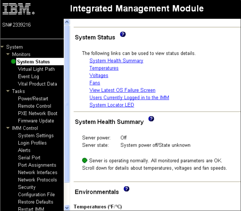
254 IBM eX5 Implementation Guide
Figure 6-30 Integrated Management Module System Status
When an actual hardware error is detected in the server, the system status is represented by
a red X. The System Health Summary will provide information about the errors presently
unresolved in the server, as shown in Figure 6-31 on page 255.

Chapter 6. IBM System x3850 X5 and x3950 X5 255
Figure 6-31 IMM System Status with a hard drive failure
Virtual light path diagnostics
If you are standing in front of the server, it is easy to track this problem by noticing the first tier
of light path diagnostics, with the error light on the operator panel at the front of the server and
on the rear of the server.
Pulling out the front operator panel reveals the second tier of light path diagnostics (as shown
in Figure 6-32) that indicates the hardware subsystem that is experiencing the error.
Figure 6-32 Tier 2 of light path diagnostics
Get IBM eX5 Implementation Guide now with the O’Reilly learning platform.
O’Reilly members experience live online training, plus books, videos, and digital content from nearly 200 publishers.