Introduction
This document describes details surrounding Cyclic Redundancy Check (CRC) errors observed on interface counters and statistics of Cisco Nexus switches.
Prerequisites
Requirements
Cisco recommends that you understand the basics of Ethernet switching and the Cisco NX-OS Command Line Interface (CLI). For more information, refer to one of these applicable documents:
- Cisco Nexus 9000 NX-OS Fundamentals Configuration Guide, Release 10.2(x)
- Cisco Nexus 9000 Series NX-OS Fundamentals Configuration Guide, Release 9.3(x)
- Cisco Nexus 9000 Series NX-OS Fundamentals Configuration Guide, Release 9.2(x)
- Cisco Nexus 9000 Series NX-OS Fundamentals Configuration Guide, Release 7.x
- Troubleshooting Ethernet
Components Used
The information in this document is based on these software and hardware versions:
- Nexus 9000 series switches starting from NX-OS software release 9.3(8)
- Nexus 3000 series switches starting from NX-OS software release 9.3(8)
The information in this document was created from devices in a specific lab environment. All of the devices used in this document started with a cleared (default) configuration. If your network is live, ensure that you understand the potential impact of any command.
The information in this document was created from the devices in a specific lab environment. All of the devices used in this document started with a cleared (default) configuration. If your network is live, ensure that you understand the potential impact of any command.
Background Information
This document describes details surrounding Cyclic Redundancy Check (CRC) errors observed on interface counters on Cisco Nexus series switches. This document describes what a CRC is, how it is used in the Frame Check Sequence (FCS) field of Ethernet frames, how CRC errors manifest on Nexus switches, how CRC errors interact in Store-and-Forward switching and Cut-Through switching scenarios, the most likely root causes of CRC errors, and how to troubleshoot and resolve CRC errors.
Applicable Hardware
The information in this document is applicable to all Cisco Nexus Series switches. Some of the information in this document can also be applicable to other Cisco routing and switching platforms, such as Cisco Catalyst routers and switches.
CRC Definition
A CRC is an error detection mechanism commonly used in computer and storage networks to identify data changed or corrupted during transmission. When a device connected to the network needs to transmit data, the device runs a computation algorithm based on cyclic codes against the data that results in a fixed-length number. This fixed-length number is called the CRC value, but colloquially, it is often called the CRC for short. This CRC value is appended to the data and transmitted through the network towards another device. This remote device runs the same cyclic code algorithm against the data and compares the resulting value with the CRC appended to the data. If both values match, then the remote device assumes the data was transmitted across the network without being corrupted. If the values do not match, then the remote device assumes the data was corrupted during transmission across the network. This corrupted data cannot be trusted and is discarded.
CRCs are used for error detection across multiple computer networking technologies, such as Ethernet (both wired and wireless variants), Token Ring, Asynchronous Transfer Mode (ATM), and Frame Relay. Ethernet frames have a 32-bit Frame Check Sequence (FCS) field at the end of the frame (immediately after the payload of the frame) where a 32-bit CRC value is inserted.
For example, consider a scenario where two hosts named Host-A and Host-B are directly connected to each other through their Network Interface Cards (NICs). Host-A needs to send the sentence “This is an example” to Host-B over the network. Host-A crafts an Ethernet frame destined to Host-B with a payload of “This is an example” and calculates that the CRC value of the frame is a hexadecimal value of 0xABCD. Host-A inserts the CRC value of 0xABCD into the FCS field of the Ethernet frame, then transmits the Ethernet frame out of Host-A’s NIC towards Host-B.
When Host-B receives this frame, it will calculate the CRC value of the frame with the use of the exact same algorithm as Host-A. Host-B calculates that the CRC value of the frame is a hexadecimal value of 0xABCD, which indicates to Host-B that the Ethernet frame was not corrupted while the frame was transmitted to Host-B.
CRC Error Definition
A CRC error occurs when a device (either a network device or a host connected to the network) receives an Ethernet frame with a CRC value in the FCS field of the frame that does not match the CRC value calculated by the device for the frame.
This concept is best demonstrated through an example. Consider a scenario where two hosts named Host-A and Host-B are directly connected to each other through their Network Interface Cards (NICs). Host-A needs to send the sentence “This is an example” to Host-B over the network. Host-A crafts an Ethernet frame destined to Host-B with a payload of “This is an example” and calculates that the CRC value of the frame is the hexadecimal value 0xABCD. Host-A inserts the CRC value of 0xABCD into the FCS field of the Ethernet frame, then transmits the Ethernet frame out of Host-A’s NIC towards Host-B.
However, damage on the physical media connecting Host-A to Host-B corrupts the contents of the frame such that the sentence within the frame changes to “This was an example” instead of the desired payload of “This is an example”.
When Host-B receives this frame, it will calculate the CRC value of the frame including the corrupted payload. Host-B calculates that the CRC value of the frame is a hexadecimal value of 0xDEAD, which is different from the 0xABCD CRC value within the FCS field of the Ethernet frame. This difference in CRC values tells Host-B that the Ethernet frame was corrupted while the frame was transmitted to Host-B. As a result, Host-B cannot trust the contents of this Ethernet frame, so it will drop it. Host-B will usually increment some sort of error counter on its Network Interface Card (NIC) as well, such as the “input errors”, “CRC errors”, or “RX errors” counters.
Common Symptoms of CRC Errors
CRC errors typically manifest themselves in one of two ways:
- Incrementing or non-zero error counters on interfaces of network-connected devices.
- Packet/Frame loss for traffic traversing the network due to network-connected devices dropping corrupted frames.
These errors manifest themselves in slightly different ways depending on the device you are working with. These sub-sections go into detail for each type of device.
Received Errors on Windows Hosts
CRC errors on Windows hosts typically manifest as a non-zero Received Errors counter displayed in the output of the netstat -e command from the Command Prompt. An example of a non-zero Received Errors counter from the Command Prompt of a Windows host is here:
>netstat -e
Interface StatisticsReceived Sent
Bytes 1116139893 3374201234
Unicast packets 101276400 49751195
Non-unicast packets 0 0
Discards 0 0
Errors 47294 0
Unknown protocols 0
The NIC and its respective driver must support accounting of CRC errors received by the NIC in order for the number of Received Errors reported by the netstat -e command to be accurate. Most modern NICs and their respective drivers support accurate accounting of CRC errors received by the NIC.
RX Errors on Linux Hosts
CRC errors on Linux hosts typically manifest as a non-zero “RX errors” counter displayed in the output of the ifconfig command. An example of a non-zero RX errors counter from a Linux host is here:
$ ifconfig eth0
eth0: flags=4163<UP,BROADCAST,RUNNING,MULTICAST>  mtu 1500
        inet 192.0.2.10  netmask 255.255.255.128  broadcast 192.0.2.255
        inet6 fe80::10  prefixlen 64  scopeid 0x20<link>
        ether 08:62:66:be:48:9b  txqueuelen 1000  (Ethernet)
        RX packets 591511682  bytes 214790684016 (200.0 GiB)
        RX errors 478920  dropped 0  overruns 0  frame 0
        TX packets 85495109  bytes 288004112030 (268.2 GiB)
        TX errors 0  dropped 0 overruns 0  carrier 0  collisions 0
CRC errors on Linux hosts can also manifest as a non-zero “RX errors” counter displayed in the output of ip -s link show command. An example of a non-zero RX errors counter from a Linux host is here:
$ ip -s link show eth0
2: eth0: <BROADCAST,MULTICAST,UP,LOWER_UP> mtu 1500 qdisc mq state UP mode DEFAULT group default qlen 1000
    link/ether 08:62:66:84:8f:6d brd ff:ff:ff:ff:ff:ff
    RX: bytes  packets  errors  dropped overrun mcast
    32246366102 444908978 478920       647     0       419445867
    TX: bytes  packets  errors  dropped carrier collsns
    3352693923 30185715 0       0       0       0
    altname enp11s0
The NIC and its respective driver must support accounting of CRC errors received by the NIC in order for the number of RX Errors reported by the ifconfig or ip -s link show commands to be accurate. Most modern NICs and their respective drivers support accurate accounting of CRC errors received by the NIC.
CRC Errors on Network Devices
Network devices operate in one of two forwarding modes — Store-and-Forward forwarding mode, and Cut-Through forwarding mode. The way a network device handles a received CRC error differs depending on its forwarding modes. The subsections here will describe the specific behavior for each forwarding mode.
Input Errors on Store-and-Forward Network Devices
When a network device operating in a Store-and-Forward forwarding mode receives a frame, the network device will buffer the entire frame (“Store”) before you validate the frame’s CRC value, make a forwarding decision on the frame, and transmit the frame out of an interface (“Forward”). Therefore, when a network device operating in a Store-and-Forward forwarding mode receives a corrupted frame with an incorrect CRC value on a specific interface, it will drop the frame and increment the “Input Errors” counter on the interface.
In other words, corrupt Ethernet frames are not forwarded by network devices operating in a Store-and-Forward forwarding mode; they are dropped on ingress.
Cisco Nexus 7000 and 7700 Series switches operate in a Store-and-Forward forwarding mode. An example of a non-zero Input Errors counter and a non-zero CRC/FCS counter from a Nexus 7000 or 7700 Series switch is here:
switch# show interface
<snip>
Ethernet1/1 is up
  RX
    241052345 unicast packets  5236252 multicast packets  5 broadcast packets
    245794858 input packets  17901276787 bytes
    0 jumbo packets  0 storm suppression packets
    0 runts  0 giants  579204 CRC/FCS  0 no buffer
    579204 input error  0 short frame  0 overrun   0 underrun  0 ignored
    0 watchdog  0 bad etype drop  0 bad proto drop  0 if down drop
    0 input with dribble  0 input discard
    0 Rx pause
CRC errors can also manifest themselves as a non-zero “FCS-Err” counter in the output of show interface counters errors. The «Rcv-Err» counter in the output of this command will also have a non-zero value, which is the sum of all input errors (CRC or otherwise) received by the interface. An example of this is shown here:
switch# show interface counters errors
<snip>
--------------------------------------------------------------------------------
Port          Align-Err    FCS-Err   Xmit-Err    Rcv-Err  UnderSize OutDiscards
--------------------------------------------------------------------------------
Eth1/1                0     579204          0     579204          0           0
Input and Output Errors on Cut-Through Network Devices
When a network device operating in a Cut-Through forwarding mode starts to receive a frame, the network device will make a forwarding decision on the frame’s header and begin transmitting the frame out of an interface as soon as it receives enough of the frame to make a valid forwarding decision. As frame and packet headers are at the beginning of the frame, this forwarding decision is usually made before the payload of the frame is received.
The FCS field of an Ethernet frame is at the end of the frame, immediately after the frame’s payload. Therefore, a network device operating in a Cut-Through forwarding mode will already have started transmitting the frame out of another interface by the time it can calculate the CRC of the frame. If the CRC calculated by the network device for the frame does not match the CRC value present in the FCS field, that means the network device forwarded a corrupted frame into the network. When this happens, the network device will increment two counters:
- The “Input Errors” counter on the interface where the corrupted frame was originally received.
- The “Output Errors” counter on all interfaces where the corrupted frame was transmitted. For unicast traffic, this will typically be a single interface – however, for broadcast, multicast, or unknown unicast traffic, this could be one or more interfaces.
An example of this is shown here, where the output of the show interface command indicates multiple corrupted frames were received on Ethernet1/1 of the network device and transmitted out of Ethernet1/2 due to the Cut-Through forwarding mode of the network device:
switch# show interface
<snip>
Ethernet1/1 is up
RX
46739903 unicast packets 29596632 multicast packets 0 broadcast packets
76336535 input packets 6743810714 bytes
15 jumbo packets 0 storm suppression bytes
0 runts 0 giants 47294 CRC 0 no buffer
47294 input error 0 short frame 0 overrun 0 underrun 0 ignored
0 watchdog 0 bad etype drop 0 bad proto drop 0 if down drop
0 input with dribble 0 input discard
0 Rx pauseEthernet1/2 is up
TX
46091721 unicast packets 2852390 multicast packets 102619 broadcast packets
49046730 output packets 3859955290 bytes
50230 jumbo packets
47294 output error 0 collision 0 deferred 0 late collision
0 lost carrier 0 no carrier 0 babble 0 output discard
0 Tx pause
CRC errors can also manifest themselves as a non-zero “FCS-Err” counter on the ingress interface and non-zero «Xmit-Err» counters on egress interfaces in the output of show interface counters errors. The «Rcv-Err» counter on the ingress interface in the output of this command will also have a non-zero value, which is the sum of all input errors (CRC or otherwise) received by the interface. An example of this is shown here:
switch# show interface counters errors
<snip>
--------------------------------------------------------------------------------
Port          Align-Err    FCS-Err   Xmit-Err    Rcv-Err  UnderSize OutDiscards
--------------------------------------------------------------------------------
Eth1/1                0      47294          0      47294          0           0
Eth1/2                0          0      47294          0          0           0
The network device will also modify the CRC value in the frame’s FCS field in a specific manner that signifies to upstream network devices that this frame is corrupt. This behavior is known as “stomping” the CRC. The precise manner in which the CRC is modified varies from one platform to another, but generally, it involves inverting the current CRC value present in the frame’s FCS field. An example of this is here:
Original CRC: 0xABCD (1010101111001101)
Stomped CRC:  0x5432 (0101010000110010)
As a result of this behavior, network devices operating in a Cut-Through forwarding mode can propagate a corrupt frame throughout a network. If a network consists of multiple network devices operating in a Cut-Through forwarding mode, a single corrupt frame can cause input error and output error counters to increment on multiple network devices within your network.
Trace and Isolate CRC Errors
The first step in order to identify and resolve the root cause of CRC errors is isolating the source of the CRC errors to a specific link between two devices within your network. One device connected to this link will have an interface output errors counter with a value of zero or is not incrementing, while the other device connected to this link will have a non-zero or incrementing interface input errors counter. This suggests that traffic egresses the interface of one device intact is corrupted at the time of the transmission to the remote device, and is counted as an input error by the ingress interface of the other device on the link.
Identifying this link in a network consisting of network devices operating in a Store-and-Forward forwarding mode is a straightforward task. However, identifying this link in a network consisting of network devices operating in a Cut-Through forwarding mode is more difficult, as many network devices will have non-zero input and output error counters. An example of this phenomenon can be seen in the topology here, where the link highlighted in red is damaged such that traffic traversing the link is corrupted. Interfaces labeled with a red «I» indicate interfaces that could have non-zero input errors, while interfaces labeled with a blue «O» indicate interfaces that could have non-zero output errors.
Identifying the faulty link requires you to recursively trace the «path» corrupted frames follow in the network through non-zero input and output error counters, with non-zero input errors pointing upstream towards the damaged link in the network. This is demonstrated in the diagram here.
A detailed process for tracing and identifying a damaged link is best demonstrated through an example. Consider the topology here:
In this topology, interface Ethernet1/1 of a Nexus switch named Switch-1 is connected to a host named Host-1 through Host-1’s Network Interface Card (NIC) eth0. Interface Ethernet1/2 of Switch-1 is connected to a second Nexus switch, named Switch-2, through Switch-2’s interface Ethernet1/2. Interface Ethernet1/1 of Switch-2 is connected to a host named Host-2 through Host-2’s NIC eth0.
The link between Host-1 and Switch-1 through Switch-1’s Ethernet1/1 interface is damaged, causing traffic that traverses the link to be intermittently corrupted. However, we do not yet know that this link is damaged. We must trace the path the corrupted frames leave in the network through non-zero or incrementing input and output error counters to locate the damaged link in this network.
In this example, Host-2’s NIC reports that it is receiving CRC errors.
Host-2$ ip -s link show eth0
2: eth0: <BROADCAST,MULTICAST,UP,LOWER_UP> mtu 1500 qdisc mq state UP mode DEFAULT group default qlen 1000
    link/ether 00:50:56:84:8f:6d brd ff:ff:ff:ff:ff:ff
    RX: bytes  packets  errors  dropped overrun mcast
    32246366102 444908978 478920       647     0       419445867
    TX: bytes  packets  errors  dropped carrier collsns
    3352693923 30185715 0       0       0       0
    altname enp11s0
You know that Host-2’s NIC connects to Switch-2 via interface Ethernet1/1. You can confirm that interface Ethernet1/1 has a non-zero output errors counter with the show interface command.
Switch-2# show interface
<snip>
Ethernet1/1 is up
admin state is up, Dedicated Interface
    RX
      30184570 unicast packets  872 multicast packets  273 broadcast packets
      30185715 input packets  3352693923 bytes
      0 jumbo packets  0 storm suppression bytes
      0 runts  0 giants 0 CRC  0 no buffer
      0 input error  0 short frame  0 overrun   0 underrun  0 ignored
      0 watchdog  0 bad etype drop  0 bad proto drop  0 if down drop
      0 input with dribble  0 input discard
      0 Rx pause
    TX
      444907944 unicast packets  932 multicast packets  102 broadcast packets
      444908978 output packets  32246366102 bytes
      0 jumbo packets
      478920 output error  0 collision  0 deferred  0 late collision
      0 lost carrier  0 no carrier  0 babble  0 output discard
      0 Tx pause
Since the output errors counter of interface Ethernet1/1 is non-zero, there is most likely another interface of Switch-2 that has a non-zero input errors counter. You can use the show interface counters errors non-zero command in order to identify if any interfaces of Switch-2 have a non-zero input errors counter.
Switch-2# show interface counters errors non-zero
<snip>
--------------------------------------------------------------------------------
Port          Align-Err    FCS-Err   Xmit-Err    Rcv-Err  UnderSize OutDiscards
--------------------------------------------------------------------------------
Eth1/1                0          0     478920          0          0           0
Eth1/2                0     478920          0     478920          0           0

--------------------------------------------------------------------------------
Port         Single-Col  Multi-Col   Late-Col  Exces-Col  Carri-Sen       Runts
--------------------------------------------------------------------------------

--------------------------------------------------------------------------------
Port          Giants SQETest-Err Deferred-Tx IntMacTx-Er IntMacRx-Er Symbol-Err
--------------------------------------------------------------------------------

--------------------------------------------------------------------------------
Port         InDiscards
--------------------------------------------------------------------------------
You can see that Ethernet1/2 of Switch-2 has a non-zero input errors counter. This suggests that Switch-2 receives corrupted traffic on this interface. You can confirm which device is connected to Ethernet1/2 of Switch-2 through the Cisco Discovery Protocol (CDP) or Link Local Discovery Protocol (LLDP) features. An example of this is shown here with the show cdp neighbors command.
Switch-2# show cdp neighbors
<snip>
    Capability Codes: R - Router, T - Trans-Bridge, B - Source-Route-Bridge
    S - Switch, H - Host, I - IGMP, r - Repeater,
    V - VoIP-Phone, D - Remotely-Managed-Device,
    s - Supports-STP-Dispute

Device-ID          Local Intrfce  Hldtme Capability  Platform      Port ID
Switch-1(FDO12345678)
                    Eth1/2         125    R S I s   N9K-C93180YC- Eth1/2
You now know that Switch-2 is receiving corrupted traffic on its Ethernet1/2 interface from Switch-1’s Ethernet1/2 interface, but you do not yet know whether the link between Switch-1’s Ethernet1/2 and Switch-2’s Ethernet1/2 is damaged and causes the corruption, or if Switch-1 is a cut-through switch forwarding corrupted traffic it receives. You must log into Switch-1 to verify this.
You can confirm Switch-1’s Ethernet1/2 interface has a non-zero output errors counter with the show interfaces command.
Switch-1# show interface
<snip>
Ethernet1/2 is up
admin state is up, Dedicated Interface
    RX
      30581666 unicast packets  178 multicast packets  931 broadcast packets
      30582775 input packets  3352693923 bytes
      0 jumbo packets  0 storm suppression bytes
      0 runts  0 giants 0 CRC  0 no buffer
      0 input error  0 short frame  0 overrun   0 underrun  0 ignored
      0 watchdog  0 bad etype drop  0 bad proto drop  0 if down drop
      0 input with dribble  0 input discard
      0 Rx pause
    TX
      454301132 unicast packets  734 multicast packets  72 broadcast packets
      454301938 output packets  32246366102 bytes
      0 jumbo packets
      478920 output error  0 collision  0 deferred  0 late collision
      0 lost carrier  0 no carrier  0 babble  0 output discard
      0 Tx pause
You can see that Ethernet1/2 of Switch-1 has a non-zero output errors counter. This suggests that the link between Switch-1’s Ethernet1/2 and Switch-2’s Ethernet1/2 is not damaged — instead, Switch-1 is a cut-through switch forwarding corrupted traffic it receives on some other interface. As previously demonstrated with Switch-2, you can use the show interface counters errors non-zero command in order to identify if any interfaces of Switch-1 have a non-zero input errors counter.
Switch-1# show interface counters errors non-zero
<snip>
--------------------------------------------------------------------------------
Port          Align-Err    FCS-Err   Xmit-Err    Rcv-Err  UnderSize OutDiscards
--------------------------------------------------------------------------------
Eth1/1                0     478920          0     478920          0           0
Eth1/2                0          0     478920          0          0           0

--------------------------------------------------------------------------------
Port         Single-Col  Multi-Col   Late-Col  Exces-Col  Carri-Sen       Runts
--------------------------------------------------------------------------------

--------------------------------------------------------------------------------
Port          Giants SQETest-Err Deferred-Tx IntMacTx-Er IntMacRx-Er Symbol-Err
--------------------------------------------------------------------------------

--------------------------------------------------------------------------------
Port         InDiscards
--------------------------------------------------------------------------------
You can see that Ethernet1/1 of Switch-1 has a non-zero input errors counter. This suggests that Switch-1 is receiving corrupted traffic on this interface. We know that this interface connects to Host-1’s eth0 NIC. We can review Host-1’s eth0 NIC interface statistics to confirm whether Host-1 sends corrupted frames out of this interface.
Host-1$ ip -s link show eth0
2: eth0: <BROADCAST,MULTICAST,UP,LOWER_UP> mtu 1500 qdisc mq state UP mode DEFAULT group default qlen 1000
    link/ether 00:50:56:84:8f:6d brd ff:ff:ff:ff:ff:ff
    RX: bytes  packets  errors  dropped overrun mcast
    73146816142 423112898 0       0     0       437368817
    TX: bytes  packets  errors  dropped carrier collsns
    3312398924 37942624 0       0       0       0
    altname enp11s0
The eth0 NIC statistics of Host-1 suggest the host is not transmitting corrupted traffic. This suggests that the link between Host-1’s eth0 and Switch-1’s Ethernet1/1 is damaged and is the source of this traffic corruption. Further troubleshooting will need to be performed on this link to identify the faulty component causing this corruption and replace it.
Root Causes of CRC Errors
The most common root cause of CRC errors is a damaged or malfunctioning component of a physical link between two devices. Examples include:
- Failing or damaged physical medium (copper or fiber) or Direct Attach Cables (DACs).
- Failing or damaged transceivers/optics.
- Failing or damaged patch panel ports.
- Faulty network device hardware (including specific ports, line card Application-Specific Integrated Circuits [ASICs], Media Access Controls [MACs], fabric modules, etc.),
- Malfunctioning network interface card inserted in a host.
It is also possible for one or more misconfigured devices to inadvertently causes CRC errors within a network. One example of this is a Maximum Transmission Unit (MTU) configuration mismatch between two or more devices within the network causing large packets to be incorrectly truncated. Identifying and resolving this configuration issue can correct CRC errors within a network as well.
Resolve CRC Errors
You can identify the specific malfunctioning component through a process of elimination:
- Replace the physical medium (either copper or fiber) or DAC with a known-good physical medium of the same type.
- Replace the transceiver inserted in one device’s interface with a known-good transceiver of the same model. If this does not resolve the CRC errors, replace the transceiver inserted in the other device’s interface with a known-good transceiver of the same model.
- If any patch panels are used as part of the damaged link, move the link to a known-good port on the patch panel. Alternatively, eliminate the patch panel as a potential root cause by connecting the link without using the patch panel if possible.
- Move the damaged link to a different, known-good port on each device. You will need to test multiple different ports to isolate a MAC, ASIC, or line card failure.
- If the damaged link involves a host, move the link to a different NIC on the host. Alternatively, connect the damaged link to a known-good host to isolate a failure of the host’s NIC.
If the malfunctioning component is a Cisco product (such as a Cisco network device or transceiver) that is covered by an active support contract, you can open a support case with Cisco TAC detailing your troubleshooting to have the malfunctioning component replaced through a Return Material Authorization (RMA).
Related Information
- Nexus 9000 Cloud Scale ASIC CRC Identification & Tracing Procedure
- Technical Support & Documentation — Cisco Systems
Содержание
- Understand Cyclic Redundancy Check Errors on Nexus Switches
- Available Languages
- Download Options
- Bias-Free Language
- Contents
- Introduction
- Prerequisites
- Requirements
- Components Used
- Background Information
- Applicable Hardware
- CRC Definition
- CRC Error Definition
- Common Symptoms of CRC Errors
- Received Errors on Windows Hosts
- RX Errors on Linux Hosts
- CRC Errors on Network Devices
- Input Errors on Store-and-Forward Network Devices
- Input and Output Errors on Cut-Through Network Devices
- Trace and Isolate CRC Errors
- Root Causes of CRC Errors
- Resolve CRC Errors
Understand Cyclic Redundancy Check Errors on Nexus Switches
Available Languages
Download Options
Bias-Free Language
The documentation set for this product strives to use bias-free language. For the purposes of this documentation set, bias-free is defined as language that does not imply discrimination based on age, disability, gender, racial identity, ethnic identity, sexual orientation, socioeconomic status, and intersectionality. Exceptions may be present in the documentation due to language that is hardcoded in the user interfaces of the product software, language used based on RFP documentation, or language that is used by a referenced third-party product. Learn more about how Cisco is using Inclusive Language.
Contents
Introduction
This document describes details surrounding Cyclic Redundancy Check (CRC) errors observed on interface counters and statistics of Cisco Nexus switches.
Prerequisites
Requirements
Cisco recommends that you understand the basics of Ethernet switching and the Cisco NX-OS Command Line Interface (CLI). For more information, refer to one of these applicable documents:
Components Used
The information in this document is based on these software and hardware versions:
- Nexus 9000 series switches starting from NX-OS software release 9.3(8)
- Nexus 3000 series switches starting from NX-OS software release 9.3(8)
The information in this document was created from devices in a specific lab environment. All of the devices used in this document started with a cleared (default) configuration. If your network is live, ensure that you understand the potential impact of any command.
The information in this document was created from the devices in a specific lab environment. All of the devices used in this document started with a cleared (default) configuration. If your network is live, ensure that you understand the potential impact of any command.
Background Information
This document describes details surrounding Cyclic Redundancy Check (CRC) errors observed on interface counters on Cisco Nexus series switches. This document describes what a CRC is, how it is used in the Frame Check Sequence (FCS) field of Ethernet frames, how CRC errors manifest on Nexus switches, how CRC errors interact in Store-and-Forward switching and Cut-Through switching scenarios, the most likely root causes of CRC errors, and how to troubleshoot and resolve CRC errors.
Applicable Hardware
The information in this document is applicable to all Cisco Nexus Series switches. Some of the information in this document can also be applicable to other Cisco routing and switching platforms, such as Cisco Catalyst routers and switches.
CRC Definition
A CRC is an error detection mechanism commonly used in computer and storage networks to identify data changed or corrupted during transmission. When a device connected to the network needs to transmit data, the device runs a computation algorithm based on cyclic codes against the data that results in a fixed-length number. This fixed-length number is called the CRC value, but colloquially, it is often called the CRC for short. This CRC value is appended to the data and transmitted through the network towards another device. This remote device runs the same cyclic code algorithm against the data and compares the resulting value with the CRC appended to the data. If both values match, then the remote device assumes the data was transmitted across the network without being corrupted. If the values do not match, then the remote device assumes the data was corrupted during transmission across the network. This corrupted data cannot be trusted and is discarded.
CRCs are used for error detection across multiple computer networking technologies, such as Ethernet (both wired and wireless variants), Token Ring, Asynchronous Transfer Mode (ATM), and Frame Relay. Ethernet frames have a 32-bit Frame Check Sequence (FCS) field at the end of the frame (immediately after the payload of the frame) where a 32-bit CRC value is inserted.
For example, consider a scenario where two hosts named Host-A and Host-B are directly connected to each other through their Network Interface Cards (NICs). Host-A needs to send the sentence “This is an example” to Host-B over the network. Host-A crafts an Ethernet frame destined to Host-B with a payload of “This is an example” and calculates that the CRC value of the frame is a hexadecimal value of 0xABCD. Host-A inserts the CRC value of 0xABCD into the FCS field of the Ethernet frame, then transmits the Ethernet frame out of Host-A’s NIC towards Host-B.
When Host-B receives this frame, it will calculate the CRC value of the frame with the use of the exact same algorithm as Host-A. Host-B calculates that the CRC value of the frame is a hexadecimal value of 0xABCD, which indicates to Host-B that the Ethernet frame was not corrupted while the frame was transmitted to Host-B.
CRC Error Definition
A CRC error occurs when a device (either a network device or a host connected to the network) receives an Ethernet frame with a CRC value in the FCS field of the frame that does not match the CRC value calculated by the device for the frame.
This concept is best demonstrated through an example. Consider a scenario where two hosts named Host-A and Host-B are directly connected to each other through their Network Interface Cards (NICs). Host-A needs to send the sentence “This is an example” to Host-B over the network. Host-A crafts an Ethernet frame destined to Host-B with a payload of “This is an example” and calculates that the CRC value of the frame is the hexadecimal value 0xABCD. Host-A inserts the CRC value of 0xABCD into the FCS field of the Ethernet frame, then transmits the Ethernet frame out of Host-A’s NIC towards Host-B.
However, damage on the physical media connecting Host-A to Host-B corrupts the contents of the frame such that the sentence within the frame changes to “This was an example” instead of the desired payload of “This is an example”.
When Host-B receives this frame, it will calculate the CRC value of the frame including the corrupted payload. Host-B calculates that the CRC value of the frame is a hexadecimal value of 0xDEAD, which is different from the 0xABCD CRC value within the FCS field of the Ethernet frame. This difference in CRC values tells Host-B that the Ethernet frame was corrupted while the frame was transmitted to Host-B. As a result, Host-B cannot trust the contents of this Ethernet frame, so it will drop it. Host-B will usually increment some sort of error counter on its Network Interface Card (NIC) as well, such as the “input errors”, “CRC errors”, or “RX errors” counters.
Common Symptoms of CRC Errors
CRC errors typically manifest themselves in one of two ways:
- Incrementing or non-zero error counters on interfaces of network-connected devices.
- Packet/Frame loss for traffic traversing the network due to network-connected devices dropping corrupted frames.
These errors manifest themselves in slightly different ways depending on the device you are working with. These sub-sections go into detail for each type of device.
Received Errors on Windows Hosts
CRC errors on Windows hosts typically manifest as a non-zero Received Errors counter displayed in the output of the netstat -e command from the Command Prompt. An example of a non-zero Received Errors counter from the Command Prompt of a Windows host is here:
The NIC and its respective driver must support accounting of CRC errors received by the NIC in order for the number of Received Errors reported by the netstat -e command to be accurate. Most modern NICs and their respective drivers support accurate accounting of CRC errors received by the NIC.
RX Errors on Linux Hosts
CRC errors on Linux hosts typically manifest as a non-zero “RX errors” counter displayed in the output of the ifconfig command. An example of a non-zero RX errors counter from a Linux host is here:
CRC errors on Linux hosts can also manifest as a non-zero “RX errors” counter displayed in the output of ip -s link show command. An example of a non-zero RX errors counter from a Linux host is here:
The NIC and its respective driver must support accounting of CRC errors received by the NIC in order for the number of RX Errors reported by the ifconfig or ip -s link show commands to be accurate. Most modern NICs and their respective drivers support accurate accounting of CRC errors received by the NIC.
CRC Errors on Network Devices
Network devices operate in one of two forwarding modes — Store-and-Forward forwarding mode, and Cut-Through forwarding mode. The way a network device handles a received CRC error differs depending on its forwarding modes. The subsections here will describe the specific behavior for each forwarding mode.
Input Errors on Store-and-Forward Network Devices
When a network device operating in a Store-and-Forward forwarding mode receives a frame, the network device will buffer the entire frame (“Store”) before you validate the frame’s CRC value, make a forwarding decision on the frame, and transmit the frame out of an interface (“Forward”). Therefore, when a network device operating in a Store-and-Forward forwarding mode receives a corrupted frame with an incorrect CRC value on a specific interface, it will drop the frame and increment the “Input Errors” counter on the interface.
In other words, corrupt Ethernet frames are not forwarded by network devices operating in a Store-and-Forward forwarding mode; they are dropped on ingress.
Cisco Nexus 7000 and 7700 Series switches operate in a Store-and-Forward forwarding mode. An example of a non-zero Input Errors counter and a non-zero CRC/FCS counter from a Nexus 7000 or 7700 Series switch is here:
CRC errors can also manifest themselves as a non-zero “FCS-Err” counter in the output of show interface counters errors. The «Rcv-Err» counter in the output of this command will also have a non-zero value, which is the sum of all input errors (CRC or otherwise) received by the interface. An example of this is shown here:
Input and Output Errors on Cut-Through Network Devices
When a network device operating in a Cut-Through forwarding mode starts to receive a frame, the network device will make a forwarding decision on the frame’s header and begin transmitting the frame out of an interface as soon as it receives enough of the frame to make a valid forwarding decision. As frame and packet headers are at the beginning of the frame, this forwarding decision is usually made before the payload of the frame is received.
The FCS field of an Ethernet frame is at the end of the frame, immediately after the frame’s payload. Therefore, a network device operating in a Cut-Through forwarding mode will already have started transmitting the frame out of another interface by the time it can calculate the CRC of the frame. If the CRC calculated by the network device for the frame does not match the CRC value present in the FCS field, that means the network device forwarded a corrupted frame into the network. When this happens, the network device will increment two counters:
- The “Input Errors” counter on the interface where the corrupted frame was originally received.
- The “Output Errors” counter on all interfaces where the corrupted frame was transmitted. For unicast traffic, this will typically be a single interface – however, for broadcast, multicast, or unknown unicast traffic, this could be one or more interfaces.
An example of this is shown here, where the output of the show interface command indicates multiple corrupted frames were received on Ethernet1/1 of the network device and transmitted out of Ethernet1/2 due to the Cut-Through forwarding mode of the network device:
CRC errors can also manifest themselves as a non-zero “FCS-Err” counter on the ingress interface and non-zero «Xmit-Err» counters on egress interfaces in the output of show interface counters errors. The «Rcv-Err» counter on the ingress interface in the output of this command will also have a non-zero value, which is the sum of all input errors (CRC or otherwise) received by the interface. An example of this is shown here:
The network device will also modify the CRC value in the frame’s FCS field in a specific manner that signifies to upstream network devices that this frame is corrupt. This behavior is known as “stomping” the CRC. The precise manner in which the CRC is modified varies from one platform to another, but generally, it involves inverting the current CRC value present in the frame’s FCS field. An example of this is here:
As a result of this behavior, network devices operating in a Cut-Through forwarding mode can propagate a corrupt frame throughout a network. If a network consists of multiple network devices operating in a Cut-Through forwarding mode, a single corrupt frame can cause input error and output error counters to increment on multiple network devices within your network.
Trace and Isolate CRC Errors
The first step in order to identify and resolve the root cause of CRC errors is isolating the source of the CRC errors to a specific link between two devices within your network. One device connected to this link will have an interface output errors counter with a value of zero or is not incrementing, while the other device connected to this link will have a non-zero or incrementing interface input errors counter. This suggests that traffic egresses the interface of one device intact is corrupted at the time of the transmission to the remote device, and is counted as an input error by the ingress interface of the other device on the link.
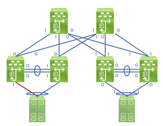
Identifying this link in a network consisting of network devices operating in a Store-and-Forward forwarding mode is a straightforward task. However, identifying this link in a network consisting of network devices operating in a Cut-Through forwarding mode is more difficult, as many network devices will have non-zero input and output error counters. An example of this phenomenon can be seen in the topology here, where the link highlighted in red is damaged such that traffic traversing the link is corrupted. Interfaces labeled with a red «I» indicate interfaces that could have non-zero input errors, while interfaces labeled with a blue «O» indicate interfaces that could have non-zero output errors.
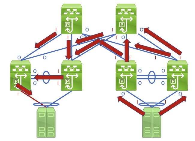
Identifying the faulty link requires you to recursively trace the «path» corrupted frames follow in the network through non-zero input and output error counters, with non-zero input errors pointing upstream towards the damaged link in the network. This is demonstrated in the diagram here.
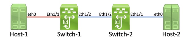
A detailed process for tracing and identifying a damaged link is best demonstrated through an example. Consider the topology here:
In this topology, interface Ethernet1/1 of a Nexus switch named Switch-1 is connected to a host named Host-1 through Host-1’s Network Interface Card (NIC) eth0. Interface Ethernet1/2 of Switch-1 is connected to a second Nexus switch, named Switch-2, through Switch-2’s interface Ethernet1/2. Interface Ethernet1/1 of Switch-2 is connected to a host named Host-2 through Host-2’s NIC eth0.
The link between Host-1 and Switch-1 through Switch-1’s Ethernet1/1 interface is damaged, causing traffic that traverses the link to be intermittently corrupted. However, we do not yet know that this link is damaged. We must trace the path the corrupted frames leave in the network through non-zero or incrementing input and output error counters to locate the damaged link in this network.
In this example, Host-2’s NIC reports that it is receiving CRC errors.
You know that Host-2’s NIC connects to Switch-2 via interface Ethernet1/1. You can confirm that interface Ethernet1/1 has a non-zero output errors counter with the show interface command.
Since the output errors counter of interface Ethernet1/1 is non-zero, there is most likely another interface of Switch-2 that has a non-zero input errors counter. You can use the show interface counters errors non-zero command in order to identify if any interfaces of Switch-2 have a non-zero input errors counter.
You can see that Ethernet1/2 of Switch-2 has a non-zero input errors counter. This suggests that Switch-2 receives corrupted traffic on this interface. You can confirm which device is connected to Ethernet1/2 of Switch-2 through the Cisco Discovery Protocol (CDP) or Link Local Discovery Protocol (LLDP) features. An example of this is shown here with the show cdp neighbors command.
You now know that Switch-2 is receiving corrupted traffic on its Ethernet1/2 interface from Switch-1’s Ethernet1/2 interface, but you do not yet know whether the link between Switch-1’s Ethernet1/2 and Switch-2’s Ethernet1/2 is damaged and causes the corruption, or if Switch-1 is a cut-through switch forwarding corrupted traffic it receives. You must log into Switch-1 to verify this.
You can confirm Switch-1’s Ethernet1/2 interface has a non-zero output errors counter with the show interfaces command.
You can see that Ethernet1/2 of Switch-1 has a non-zero output errors counter. This suggests that the link between Switch-1’s Ethernet1/2 and Switch-2’s Ethernet1/2 is not damaged — instead, Switch-1 is a cut-through switch forwarding corrupted traffic it receives on some other interface. As previously demonstrated with Switch-2, you can use the show interface counters errors non-zero command in order to identify if any interfaces of Switch-1 have a non-zero input errors counter.
You can see that Ethernet1/1 of Switch-1 has a non-zero input errors counter. This suggests that Switch-1 is receiving corrupted traffic on this interface. We know that this interface connects to Host-1’s eth0 NIC. We can review Host-1’s eth0 NIC interface statistics to confirm whether Host-1 sends corrupted frames out of this interface.
The eth0 NIC statistics of Host-1 suggest the host is not transmitting corrupted traffic. This suggests that the link between Host-1’s eth0 and Switch-1’s Ethernet1/1 is damaged and is the source of this traffic corruption. Further troubleshooting will need to be performed on this link to identify the faulty component causing this corruption and replace it.
Root Causes of CRC Errors
The most common root cause of CRC errors is a damaged or malfunctioning component of a physical link between two devices. Examples include:
- Failing or damaged physical medium (copper or fiber) or Direct Attach Cables (DACs).
- Failing or damaged transceivers/optics.
- Failing or damaged patch panel ports.
- Faulty network device hardware (including specific ports, line card Application-Specific Integrated Circuits [ASICs], Media Access Controls [MACs], fabric modules, etc.),
- Malfunctioning network interface card inserted in a host.
It is also possible for one or more misconfigured devices to inadvertently causes CRC errors within a network. One example of this is a Maximum Transmission Unit (MTU) configuration mismatch between two or more devices within the network causing large packets to be incorrectly truncated. Identifying and resolving this configuration issue can correct CRC errors within a network as well.
Resolve CRC Errors
You can identify the specific malfunctioning component through a process of elimination:
- Replace the physical medium (either copper or fiber) or DAC with a known-good physical medium of the same type.
- Replace the transceiver inserted in one device’s interface with a known-good transceiver of the same model. If this does not resolve the CRC errors, replace the transceiver inserted in the other device’s interface with a known-good transceiver of the same model.
- If any patch panels are used as part of the damaged link, move the link to a known-good port on the patch panel. Alternatively, eliminate the patch panel as a potential root cause by connecting the link without using the patch panel if possible.
- Move the damaged link to a different, known-good port on each device. You will need to test multiple different ports to isolate a MAC, ASIC, or line card failure.
- If the damaged link involves a host, move the link to a different NIC on the host. Alternatively, connect the damaged link to a known-good host to isolate a failure of the host’s NIC.
If the malfunctioning component is a Cisco product (such as a Cisco network device or transceiver) that is covered by an active support contract, you can open a support case with Cisco TAC detailing your troubleshooting to have the malfunctioning component replaced through a Return Material Authorization (RMA).
Источник
В данной статье производится описание порядка диагностики и поиска ошибок на портах коммутатора.
В примере используется коммутатор Cisco Catalyst C4948
Для диагностики ошибок на портах коммутатора Cisco необходимо подключиться к консоли
коммутатора через утилиту telnet, используя консольный порт (прямое подключение)
или по IP-адресу.
Следующим шагом мы переходим в привилегированный режим редактирования конфигурации Enable (en).
C4948> enable
или
C4948> en
Следующей командой мы можем посмотреть счетчики ошибок по всем портам коммутатора:
C4948# sh interfaces counters errors
или по одному порту gi1/33
C4948# sh interfaces gi1/33 counters errors
Вывод команды
Port       CrcAlign-Err Dropped-Bad-Pkts Collisions   Symbol-Err
Gi1/33               0                0          0            0

Port          Undersize  Oversize  Fragments      Jabbers
Gi1/33                0         0          0            0

Port         Single-Col Multi-Col   Late-Col   Excess-Col
Gi1/33                0         0          0            0

Port       Deferred-Col False-Car  Carri-Sen Sequence-Err
Gi1/33                0         0          0            0
Приведем описание наиболее важных счетчиков
| Счетчик | Описание | Возможная причина |
|---|---|---|
| CrcAlign-Err | Количество ошибок выравнивания определяется числом полученных кадров, которые не заканчиваются четным числом октетов и имеют неверную контрольную сумму CRC | Данные ошибки обычно являются результатом несоответствия дуплексных режимов или физической проблемы (такой как прокладка кабелей, неисправный порт или сетевая плата). При первом подключении кабеля к порту могут возникнуть некоторые из этих ошибок. Кроме того, если к порту подключен концентратор, ошибки могут вызвать конфликты между другими устройствами концентратора |
| Collisions | В счетчиках кадров с конфликтами содержится число пакетов, одна попытка передачи которых была неудачной, а следующая — успешной. Это означает, что в случае увеличения значения счетчика кадров с конфликтами на 2, коммутатор дважды неудачно пытался передать пакет, но третья попытка была успешной | Отбрасывание кадров вызвано чрезмерной нагрузкой трафиком данного интерфейса. Если в этих полях наблюдается рост числа пакетов, уменьшите нагрузку на данный интерфейс |
| Undersize | Это общее число принятых пакетов с длиной менее 64 октетов (без битов кадрирования, но с октетами FCS) и допустимым значением FCS | Указывает на поврежденный кадр, сформированный подключенным устройством. Убедитесь, что подключенное устройство функционирует правильно |
| Oversize | Число принятых портом из сети пакетов с длиной более 1514 байтов2 | Это может указывать на сбой оборудования либо проблемы конфигурации режима магистрального соединения для dot1q или ISL |
| Fragment | Общее число кадров с длиной менее 64 октетов (без битов кадрирования, но с октетами FCS) и неверным значением FCS | Увеличение значения этого счетчика указывает на то, что порты настроены на полудуплексный режим. Установите в настройках дуплексный режим |
| Single-Col | Число конфликтов, произошедших до того, как интерфейс успешно передал кадр носителю | Нормальное явление для полудуплексных интерфейсов, но не для полнодуплексных интерфейсов. Быстрый рост числа конфликтов указывает на высокую загрузку соединения или возможное несоответствие дуплексных режимов с присоединенным устройством |
| Multi-Col | Число множественных конфликтов произошедших до того, как порт успешно передал кадр носителю | Нормальное явление для полудуплексных интерфейсов, но не для полнодуплексных интерфейсов. Быстрый рост числа конфликтов указывает на высокую загрузку соединения или возможное несоответствие дуплексных режимов с присоединенным устройством |
| Late-Col | Количество обнаруженных конфликтов в определенном интерфейсе на последних этапах процесса передачи. Для порта со скоростью 10 Мбит/с это позднее, чем время передачи 512 битов для пакета. В системе со скоростью передачи данных 10 Мбит/с 512 битовых интервалов соответствуют 51,2 микросекунды | Ошибка, в частности, может указывать на несоответствие дуплексных режимов. В сценарии с несоответствием дуплексных режимов на стороне с полудуплексным режимом наблюдается поздний конфликт. Во время передачи со стороны с полудуплексным режимом на стороне с дуплексным режимом выполняется одновременная передача без ожидания своей очереди, что приводит к возникновению позднего конфликта. Поздние конфликты также могут указывать на слишком большую длину кабеля или сегмента Ethernet. На интерфейсах, сконфигурированных в качестве полнодуплексных, конфликты наблюдаться не должны |
| Excess-Col | Количество кадров, для которых передача через отдельный интерфейс завершилась с ошибкой из-за чрезмерного числа конфликтов. Избыточный конфликт возникает, когда для некоторого пакета конфликт регистрируется 16 раз подряд. Затем пакет отбрасывается | Чрезмерное количество конфликтов обычно обозначает, что нагрузку на данный сегмент необходимо разделить между несколькими сегментами, но может также указывать на несоответствие дуплексных режимов с присоединенным устройством. На интерфейсах, сконфигурированных в качестве полнодуплексных, конфликты наблюдаться не должны |
| Deferred-Col | Общее число кадров, первая попытка передачи которых была отложена из-за трафика в сетевом носителе | Отбрасывание кадров вызвано чрезмерной нагрузкой трафика, направленного к данному коммутатору. Если в этом поле наблюдается рост числа пакетов, уменьшите нагрузку на данный коммутатор. Может потребоваться изменение топологии сети, чтобы снизить нагрузку трафика на данный коммутатор |
| Carri-Sen | Счетчик увеличивается каждый раз, когда контроллер Ethernet собирается отослать данные по полудуплексному соединению. Контроллер обнаруживает провод и перед передачей проверяет, не занят ли он | Нормально для полудуплексного сегмента Ethernet |
Далее проверяем, включено ли обнаружение отключения из-за ошибки на порту коммутатора:
C4948# sh errdisable detect
Вывод команды
ErrDisable Reason      Detection    Mode
-----------------      ---------    ----
arp-inspection          Enabled      port
bpduguard               Enabled      port
channel-misconfig       Enabled      port
community-limit         Enabled      port
dhcp-rate-limit         Enabled      port
dtp-flap                Enabled      port
ekey                    Enabled      port
gbic-invalid            Enabled      port
inline-power            Enabled      port
invalid-policy          Enabled      port
l2ptguard               Enabled      port
link-flap               Enabled      port
link-monitor-failure    Enabled      port
lsgroup                 Enabled      port
oam-remote-failure      Enabled      port
mac-limit               Enabled      port
pagp-flap               Enabled      port
port-mode-failure       Enabled      port
pppoe-ia-rate-limit     Enabled      port
psecure-violation       Enabled      port/vlan
security-violation      Enabled      port
sfp-config-mismatch     Enabled      port
storm-control           Enabled      port
udld                    Enabled      port
unicast-flood           Enabled      port
vmps                    Enabled      port
где, по умолчанию, в колонке Detection все значения должны быть Enabled
Смотрим порты которые находятся в состоянии ошибки errdisable (порт
автоматически отключен операционной системой коммутатора, так как порт
обнаружен в состоянии ошибки):
C4948# sh errdisable recovery
Вывод команды:
ErrDisable Reason            Timer Status
-----------------            --------------
arp-inspection               Disabled
bpduguard                    Disabled
channel-misconfig            Disabled
dhcp-rate-limit              Disabled
dtp-flap                     Disabled
gbic-invalid                 Disabled
inline-power                 Disabled
l2ptguard                    Disabled
link-flap                    Disabled
mac-limit                    Disabled
link-monitor-failure         Disabled
oam-remote-failure           Disabled
pagp-flap                    Disabled
port-mode-failure            Disabled
pppoe-ia-rate-limit          Disabled
psecure-violation            Disabled
security-violation           Disabled
sfp-config-mismatch          Disabled
storm-control                Disabled
udld                         Disabled
unicast-flood                Disabled
vmps                         Disabled

Timer interval: 300 seconds

Interfaces that will be enabled at the next timeout:
где в колонке ErrDisable Reason отображается причина перехода порта в состояние errdisable.
В нашем случае портов в состоянии errdisable не обнаружено.
Просмотр подробной информации о настройках и состоянии порта коммутатора:
C4948# sh interfaces gigabitEthernet 1/33
Вывод команды
GigabitEthernet1/33 is up, line protocol is up (connected)
  Hardware is Gigabit Ethernet Port, address is 8843.e1a1.7f60 (bia 8843.e1a1.7f60)
  MTU 1500 bytes, BW 100000 Kbit, DLY 100 usec,
     reliability 255/255, txload 1/255, rxload 1/255
  Encapsulation ARPA, loopback not set
  Keepalive set (10 sec)
  Full-duplex, 100Mb/s, link type is auto, media type is 10/100/1000-TX
  input flow-control is off, output flow-control is off
  ARP type: ARPA, ARP Timeout 04:00:00
  Last input never, output never, output hang never
  Last clearing of "show interface" counters never
  Input queue: 0/2000/0/0 (size/max/drops/flushes); Total output drops: 0
  Queueing strategy: fifo
  Output queue: 0/40 (size/max)
  5 minute input rate 0 bits/sec, 0 packets/sec
  5 minute output rate 22000 bits/sec, 18 packets/sec
     249311846 packets input, 197650705208 bytes, 0 no buffer
     Received 146 broadcasts (0 multicasts)
     0 runts, 0 giants, 0 throttles
     0 input errors, 0 CRC, 0 frame, 0 overrun, 0 ignored
     0 input packets with dribble condition detected
     413450928 packets output, 82056436068 bytes, 0 underruns
     0 output errors, 0 collisions, 0 interface resets
     0 babbles, 0 late collision, 0 deferred
     0 lost carrier, 0 no carrier
     0 output buffer failures, 0 output buffers swapped out
Как видно из вывода команды, ошибок на порте коммутатора не обнаружено.
Также, набрав следующую команду, можно посмотреть статус и используемые протоколы на портах коммутатора:
C4948# sh interfaces counters protocol status
или по определенному порту:
C4948# sh interfaces gi1/33 counters protocol status
Вывод команды:
Protocols allocated:
 GigabitEthernet1/33: Other, IP, Spanning Tree, CDP
где
| Протокол | Описание |
|---|---|
IP |
Маршрутизируемый протокол сетевого уровня стека TCP/IP. |
Spanning Tree (STP) |
Канальный протокол связующего дерева. Основной задачей STP является устранение петель в топологии произвольной сети Ethernet, в которой есть один или более сетевых мостов, связанных избыточными соединениями. |
CDP |
Проприетарный протокол второго уровня, разработанный компанией Cisco Systems, позволяющий обнаруживать подключённое сетевое оборудование Cisco, его название, версию IOS и IP-адреса. |
INTELLIGENT WORK FORUMS
FOR COMPUTER PROFESSIONALS
Contact US
Thanks. We have received your request and will respond promptly.
Log In
Come Join Us!
Are you a
Computer / IT professional?
Join Tek-Tips Forums!
- Talk With Other Members
- Be Notified Of Responses
To Your Posts - Keyword Search
- One-Click Access To Your
Favorite Forums - Automated Signatures
On Your Posts - Best Of All, It’s Free!
*Tek-Tips’s functionality depends on members receiving e-mail. By joining you are opting in to receive e-mail.
Posting Guidelines
Promoting, selling, recruiting, coursework and thesis posting is forbidden.
Students Click Here
2950 CRC ERRORS INPUT ERRORS2950 CRC ERRORS INPUT ERRORS(OP) 6 Apr 06 14:02 Hi, 4507 City-Fiber Connection>>> +4507 fiber to 2950…. this is the current setting please help thanks ? sh int fa0/3 all it has on that port switchport mode access vlan 2 thats it. and thats how it was for 1.5 year never had any problems i even swap the 2950 Red Flag SubmittedThank you for helping keep Tek-Tips Forums free from inappropriate posts. |
Join Tek-Tips® Today!
Join your peers on the Internet’s largest technical computer professional community.
It’s easy to join and it’s free.
Here’s Why Members Love Tek-Tips Forums:
 Talk To Other Members
- Notification Of Responses To Questions
- Favorite Forums One Click Access
- Keyword Search Of All Posts, And More…
 Talk To Other Members
Register now while it’s still free!
Already a member? Close this window and log in.
Join Us Close
Hi …
i have a Switch 2960 …..and i had a complain from the Client that
AFTER 12 HOURS THE SWITCH GET HANG … and there can be no traffic out from the switch …and all the Netwrok goes to down ….
there is a DHCP Server setup in the Network and when Switch gets hang they can not obtain the IP address from the Server and in the mean while even Clients cant Communicate who are even in the same switch (Ping ) .There is no vlan implementaion in the Network and quite simple.
so here is the stroy what he told .
now i get the Switch and i just logged in and it wotrks fine …
i can not put the Much Host machines on it … but what i did is that
i just put the Cable comming from my network on Fa 0/1 … and then i took the my PC cable and put in Fa 0/2 . and then i reslove the IP address and it worked fine and i just kept working all the day … i was not hanged and switch was working fine ..
but on the next day tried to monitor the Packets (IN ,OUT) from the command
sh inter fa 0/1
sh inter fa 0/2
now what happen is that i saw a lots of CRC Errors and INPUT Errors at port Fa 0/2
(the port from whom my PC was connected) and on Fa 0/1 which was connected from my netwrok as no CRC Error as well as no Input Error …
i just clear the Counters and after couple of mins i observed that i again saw around 50 CRC Errors and that is a huge Amount of Errors …
then i assumed that may be Fa 0/2(on whom my PC is connected was faulty)
i changed the Port to fa 0/3 , and the many others ….and what i saw is that at whatever port i connect my PC to the port i get the CRC Errors and IPut Errors which are the same in number …lets say 53 CRC and 53 Inout ….
now i cant assume that at once all the ports are showing the CRC Errors ..
i would like every body who has a good understanding with the problem …
Plz help me out .. that what i can do and how i can solve my problem in order to Switch work fine …..
I hope i have cleared much my point to go in the detail …
i cant access the Switch as i m not in the office but i can do so after couple of hrs .
but for the time being i wanted to have a good TIP which can help me when i access my switch while i go in the morning
Regards
ASAd