Autodesk Inventor recognizes and processes most commonly used units of measurement. Every part, assembly, and drawing has a default units system. Values that you enter in dialog boxes are assumed to be in the default units unless you specify a unit name.
Changing the units system for a file
The default units are set when you create a file. However, you can change the units at any time.
In part and assembly files, the units system is set in the document settings.
In drawings, the units system is set by the dimension style and the active drafting standard. You can edit the dimension style or drafting standard to change the units system, or change the drafting standard for the drawing.
When you change the units system, all existing values in the file are converted to the new units, and all subsequent entries are assumed to be in the new units.
Using templates to set the units system
When you installed Autodesk Inventor, you specified a units system that is automatically assigned to all new files. You can change the automatically assigned units by editing the templates used to create new files, or replacing the templates with your own.
NoteTemplates are in the AutodeskInventor [version]Templates folder. Any part, assembly, or drawing file becomes a template if you save it in the Templates folder or any of its subfolders.
Overriding the default units
As you enter values into dialog boxes they are assumed to be in the default units system for the file. You can override the default units for a single entry by adding the unit name after the value. For example, 0.05 in. or 3 mm.
When you override the units, Autodesk Inventor displays your entry in the default units, but when you open the dialog box for editing, the units shows as you entered them.
Procedures
Set the units for models
When you create a part or assembly, the units of measurement in the template sets the default units of measurement for the model. You can change the default units for the active document.
- Click Tools tab
 Options panel Document Settings to open the dialog box.
 - Click the Units tab to open it.
- To change the setting for any of the measurement types or precision, click the arrow next to the edit box. Select the setting from the list.
- When you have finished the desired changes, click Apply to save them.

NoteWhen entering a value in a dialog box, you can override the default units by entering the unit name after the value. For example, 0.05 in. or 3 mm.
Autodesk Inventor converts your entry to the default units.
References
Document Settings — Units tab
Sets the default units system and dimension precision for the active model file or template.
NoteTo change the default units system applied when you create new files, change the default units in the templates that you use to create files.
|
Access: |
Click Tools tab |

Units
|
Sets the default measurement units for the file. Click the arrow next to the appropriate edit box and select from the list. |
|
|
Length Units |
Sets the default units for linear dimensions. |
|
Angle Units |
Sets the default units for angular dimensions. |
|
Time Units |
Sets the default units for time. |
|
Mass Units |
Sets the default units for mass. |
Modeling Dimension Display
|
Sets the display precision for dimensions in the model. Click the arrow next to the appropriate edit box and select from the list. |
|
|
Linear Dim Display Precision |
Controls the number of decimal places visible to the right of the decimal marker in linear dimensions. |
|
Angular Dim Display Precision |
Controls the number of decimal places visible to the right of the decimal marker in angular dimensions. |
|
Display as value |
Displays dimension as a value using settings specified in the Document Settings dialog box. |
|
Display as name |
Displays dimension as a name as defined in the Parameters dialog box. |
|
Display as expression |
Displays dimension as an expression using the equal sign. |
|
Display tolerance |
Displays dimension tolerance. |
|
Display precise value |
Displays all dimension units. |
Default Parameter Input Display
|
Sets the method of parameter display in edit boxes when a dimension or feature is edited. |
|
|
Display as value |
Displays the parameter value or numeric equation. |
|
Display as expression |
Displays the complete parameter expression. |
|
Examples |
||
|
Defined Parameter |
Display as value (in edit box) |
Display as expression (in edit box) |
| LENG = 1 mm + 2 mm | 1 mm + 2 mm | LENG = 1 mm + 2 mm |
| LENG = 3 mm | 3 mm | LENG = 3 mm |
Autodesk Inventor recognizes and processes most commonly used units of measurement. Every part, assembly, and drawing has a default units system. Values that you enter in dialog boxes are assumed to be in the default units unless you specify a unit name.
Changing the units system for a file
The default units are set when you create a file. However, you can change the units at any time.
In part and assembly files, the units system is set in the document settings.
In drawings, the units system is set by the dimension style and the active drafting standard. You can edit the dimension style or drafting standard to change the units system, or change the drafting standard for the drawing.
When you change the units system, all existing values in the file are converted to the new units, and all subsequent entries are assumed to be in the new units.
Using templates to set the units system
When you installed Autodesk Inventor, you specified a units system that is automatically assigned to all new files. You can change the automatically assigned units by editing the templates used to create new files, or replacing the templates with your own.
NoteTemplates are in the AutodeskInventor [version]Templates folder. Any part, assembly, or drawing file becomes a template if you save it in the Templates folder or any of its subfolders.
Overriding the default units
As you enter values into dialog boxes they are assumed to be in the default units system for the file. You can override the default units for a single entry by adding the unit name after the value. For example, 0.05 in. or 3 mm.
When you override the units, Autodesk Inventor displays your entry in the default units, but when you open the dialog box for editing, the units shows as you entered them.
Procedures
Set the units for models
When you create a part or assembly, the units of measurement in the template sets the default units of measurement for the model. You can change the default units for the active document.
- Click Tools tab Options panel Document Settings to open the dialog box.
- Click the Units tab to open it.
- To change the setting for any of the measurement types or precision, click the arrow next to the edit box. Select the setting from the list.
- When you have finished the desired changes, click Apply to save them.
NoteWhen entering a value in a dialog box, you can override the default units by entering the unit name after the value. For example, 0.05 in. or 3 mm.
Autodesk Inventor converts your entry to the default units.
References
Document Settings — Units tab
Sets the default units system and dimension precision for the active model file or template.
NoteTo change the default units system applied when you create new files, change the default units in the templates that you use to create files.
|
Access: |
Click Tools tab |
Units
|
Sets the default measurement units for the file. Click the arrow next to the appropriate edit box and select from the list. |
|
|
Length Units |
Sets the default units for linear dimensions. |
|
Angle Units |
Sets the default units for angular dimensions. |
|
Time Units |
Sets the default units for time. |
|
Mass Units |
Sets the default units for mass. |
Modeling Dimension Display
|
Sets the display precision for dimensions in the model. Click the arrow next to the appropriate edit box and select from the list. |
|
|
Linear Dim Display Precision |
Controls the number of decimal places visible to the right of the decimal marker in linear dimensions. |
|
Angular Dim Display Precision |
Controls the number of decimal places visible to the right of the decimal marker in angular dimensions. |
|
Display as value |
Displays dimension as a value using settings specified in the Document Settings dialog box. |
|
Display as name |
Displays dimension as a name as defined in the Parameters dialog box. |
|
Display as expression |
Displays dimension as an expression using the equal sign. |
|
Display tolerance |
Displays dimension tolerance. |
|
Display precise value |
Displays all dimension units. |
Default Parameter Input Display
|
Sets the method of parameter display in edit boxes when a dimension or feature is edited. |
|
|
Display as value |
Displays the parameter value or numeric equation. |
|
Display as expression |
Displays the complete parameter expression. |
|
Examples |
||
|
Defined Parameter |
Display as value (in edit box) |
Display as expression (in edit box) |
| LENG = 1 mm + 2 mm | 1 mm + 2 mm | LENG = 1 mm + 2 mm |
| LENG = 3 mm | 3 mm | LENG = 3 mm |
- Пресс-центр
- Блог
/
Корректный выбор единиц измерения крайне важен при построении трехмерных моделей и создании чертежей. Если перепутать настройки и построить модель в миллиметрах, а потом выяснить, что на самом деле система постоянно запрашивала значения размеров в дюймах, то результат будет плачевным – модель просто не встанет в сборку. Или случится еще более неприятная ситуация – реальную деталь изготовят по некорректной трехмерной модели и получится вроде бы та самая нужная деталь, но по размерам в 2,5 раза больше, чем необходимо!
Чтобы не попасть в такую или схожую неприятную ситуацию, необходимо знать и понимать, как и какими единицами измерения можно пользоваться при работе в Autodesk Inventor. С радостью делимся с вами этой важной и полезной информацией!
Для начала нужно усвоить, что в Inventor настройки единиц измерения не являются глобальным параметром и уникальны для каждого файла! С одной стороны, это дает гибкость при работе в программе, когда часть документов можно разрабатывать в миллиметрах, а часть в дюймах. С другой стороны, можно по ошибке изменить или забыть переключить единицы в отдельно взятом файле и в итоге испортить модель или чертеж.
Единицы по умолчанию
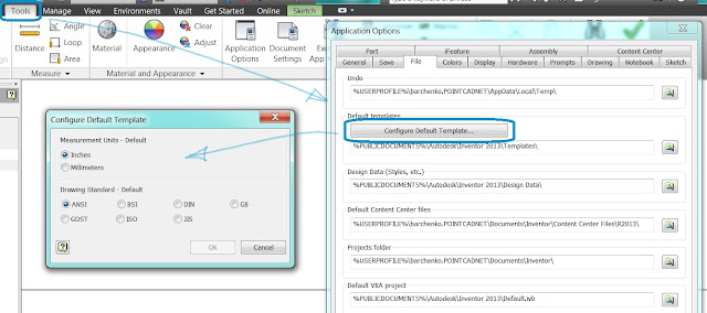
При инсталляции Inventor в качестве единиц измерения по умолчанию устанавливаются миллиметры (метрическая система) или дюймы (имперская система), все зависит от того, какую языковую версию Inventor вы используете. Настройки по умолчанию влияют на все вновь создаваемые документы Inventor, когда вы делаете это не с помощью выбора конкретного шаблона, а выбираете нужный документ на стартовой странице программы или в строке быстрого доступа. Для изменения единиц по умолчанию войдите в параметры приложения и на вкладке «Файлы» нажмите кнопку «Настроить шаблон по умолчанию…», после чего в появившемся окне выберите необходимые опции.

Единицы измерения в трехмерных моделях
Для моделей деталей IPT и моделей сборок ASM настройки единиц измерения производятся в одном месте. На ленте на вкладке «Инструменты» запустите команду «Параметры процесса моделирования» и в появившемся окне на вкладке «Единицы» установите необходимые параметры.

Единицы измерения в чертежах
В файлах чертежей нет явного переключателя мм/дюймы, в них единицы измерения привязаны к стандартам оформления. При выборе нужного стандарта в документе устанавливаются соответствующие единицы и изменяются стили объектов оформления чертежей. Например, при выборе стандарта ANSI будет включена имперская система, а при выборе ISO или GOST – метрическая. Для изменения системы единиц в конкретном файле чертежа на ленте на вкладке «Инструменты» запустите команду «Параметры процесса моделирования» и в появившемся окне на вкладке «Стандарт» выберите нужный стандарт оформления.

Опубликовано 25 Марта 2019
For parts, assemblies, and presentations the template file sets the default units used in a file. For drawings, the active standard and the dimension style specified in the template file sets the units. But often you may require this information in a different format. In this blog, we look at how to change the default unit of measure in Inventor 2021.
Inventor – Override Units in Parts, Assemblies, and Presentations
To change the default unit of measure in the active file, go to Tools tab  Options panel Document Settings and then select the Units tab in the dialog box. Select the Length drop-list to change units such as inches to mm. When you change the units setting, all existing values in the file display as the new units. All subsequent entries are displayed in the new units. Unit value settings are saved with the file.

You can also override the default units in any value box. For example, you can type 12mm in the dimension value box of a file using an inch unit of length. The result is displayed as 0.472, but the original 12mm unit value is retained and appears in the value box when you edit.
Inventor – Override Units in Drawings
In drawings, the dimension style, and the active drafting standard set the units system. Edit the dimension style or drafting standard to change the units system.
To override the default unit of measure in the active file, do any of the following:
All subsequent entries are displayed in the new units. Unit value settings are saved with the file.
Change the default units in a template file
If you like to find out more about Autodesk Inventor and how Quadra can help support you with your ongoing design projects – Click here
Advanced Autodesk Training Courses
Maximise your business productivity today with an Advanced Autodesk Inventor training course. Courses are designed to help you gain maximum benefit from all the software enhancements available within Inventor, whilst providing you with more efficient methods of working. For more information about our Advanced Training Courses Click Here
More about Quadra Solutions
Quadra Solutions Ltd specialise in design and data management software solutions for the manufacturing, construction, engineering and PCB design industries. Quadra is a Gold Autodesk Partner, an accredited training centre and specialists in PCB design. Inventor, Revit, AutoCAD,Collections and Vault software help our customers to design, visualise, innovate and implement solutions that grow and develop their business.
Our software solutions, consultancy, training and technical support are some of the best in the industry. With a wealth of experience and knowledge, Quadra specialises in helping businesses adopt efficient and effective design workflows, innovate and embed data management solutions. We pride ourselves on our consultative approach to working with customers as their technology partner. For more information about Quadra please contact us.
Talk to our team 01254 3018888 Live Chat
Настройка по умолчанию единиц измерения в эскизе и стандарта оформления
Всем привет!
Я на минуточку. Наверное уже многие потестили Inventor 2013.
Все нашли как стандарт ГОСТ и размеры в миллиметрах по умолчанию настраивать?
И так, решение:
Вкладка Tools -> Application Option.
В диалоговом окне Application Option — File, раздел Default templates кнопка Configure Default Template.
Открывается диалоговое окно Configure Default Template, ставим галочки Millimeters и GOST.
Видеоролика здесь не будет, потому что и так все просто.
Что касается моих обещаний пользователям, по созданию деталей используя iFeatures, все помню, совесть не дает спать. Сейчас на работе готовим очень интересный проект для лицензированных пользователей продуктов Autodesk.
Популярные сообщения из этого блога
Задача. Создать развертку усеченного конуса инструментами Autodesk Inventor. Решение. Эта задача была успешна решена с использованием Autodesk Inventor 10. Одно из решений было очень красиво показано здесь . Однако считаю этот подход не полным, но безусловно единственным. Обычно усеченный конус приходится создавать по каким-то чертежам, и чаще всего это его высота и два диаметра. Возьмем для примера самые простые размеры конуса. Верхний диаметр — 50 мм, диаметр основания 100 мм, высота 100 мм. Как на рисунке После того, как Вы сделаете такой эскиз, необходимо «повращать» и получить модель усеченного конуса, как на рисунке. Следующим шагом получаем тонкостенную оболочку. Для простоты я использовал установленный по умолчанию размер толщины стенки в 1 мм. Обязательно необходимо указать и верх усеченного конуса и его основание. Теперь необходимо рассечь тело конуса, для того чтоб получить развертку. Рассечь можно используя выдавливание или же создать поверхность, которая буде
Всем привет! Проглядывая форум Community Autodesk наткнулся на интересный вопрос , на мой взгляд. Развернутый ответ сейчас предстанет перед Вами, уважаемые читатели. И так. Надо создать отверстие под углом к оси вращения. Предлагаю усложнить задачу. Предлагаю построить отверстие под разными углами. Посмотрим на картинку. Перейдем к решению. Отверстие возможно построить используя следующие способы: по эскизу; используя линейные размеры от граней или кромок; по плоскости и концентрической кромки или концентрической поверхности; в точке. Для построения такого сложного отверстия необходимо использовать метод построения «в точке». Используя метод «в точке» необходимо построить «рабочую ось» и «рабочую точку». Предположим мне хочется построить отверстие под углом к оси в 35 градусов, и 15 градусов в плане. Начнем? Создаем эскиз в любой плоскости, проходящей через ось цилиндра. На эскизе рисуем отрезок, ставим размеры, которые описывают положения этого
Кроме основных системных настроек здесь можно производить настройку параметров моделирования. Выполняется это через отдельное программное окно Параметры процесса моделирования. Чтобы вызвать его на рабочий экран, необходимо поочередно войти в Сервис > Процесс моделирования. В этой вкладке доступны для редактирования режимы редактирования эскизов и моделей, активные стили, единицы измерения и мн. др.
Вкладка Стандарт
Здесь можно назначить активный стандарт для используемого в работе файла. Средами его применения — изделия, схемы, эскизы, детали, чертежи.
Список Текущий стиль позволяет установить стиль освещения. Может использоваться в программе в одном из 2-х вариантов — Два источника или Обычный.
В разделе Материал по умолчанию представлен большой список материалов, которые применяются при построении того или иного изделия.

Вкладка Единицы
Понадобиться не только при формировании системы единиц, но и для указания точности размеров. Может быть использована для активного файла или для программного шаблона.

Также стоит заметить, что в данном разделе пользователь имеет возможность воспользоваться и некоторыми другими параметрами, такими как длина, угол, масса и время.
А) Длина – используется для установки единицы измерения (см, мм, дюйм и др.)
Б) Угол — может быть использован для угловых размеров (градус, радиан)
В) Масса — выбирают для массы (кг, грамм, фунт)
Г) Время — отвечает за времени (1сек, 1 мин).
Необходимые данные для обеспечения точности изображение на экране модели содержатся в отдельном разделе Отображение размеров модели. Там вы можете регулировать прежде всего точность линейных размеров в десятичных знаках, а также угловые размеры.
Чтобы сделать выбор в пользу одного из доступных способом отображения размеров, в программе предусмотрены переключатели:
- Как значения
- Как имена параметров
- Как формулы
- С допусками
- Точные значения
Вкладка Эскиз
Занимаясь построением эскиза, нередко приходится задавать показатель шага привязки. И для удобства пользователя в приложении имеется вкладка Эскиз. Именно там можно выполнить привязку и параметров сетки, и других важных аспектов для активного файла детали/чертежа. Непосредственно шаговая привязка – это расстояние между дискретными точками, которые берутся за основу при определении места положения курсора в процессе создания эскизов. При этом стоит учитывать, что:
- X — значение шага для координатной оси X
- Y — значение шага для координатной оси Y
Немаловажным аспектом этой вкладки является параметр Отображение сетки. Он станет находкой для того, чтобы узнать расстояние между линиями сетки для детали или рабочего чертежа. Не забывайте, что сетка расположена всегда в соответствии с координатами эскиза. При этом основные линии можно понять по тому, что на сетке они выглядят более жирными.
Включение/отключение этого аспекта выполняется через Сервис > Настройка. А для 3D-эскизов необходимо дополнительно вносить в поле Радиус автосопряжения значение, благодаря которому автоматически сглаживаются все существующие на рабочем эскизе пересечения.

Вкладка Деталь
Процесс настройки параметров адаптивности, а также параллельное включения/исключение промежуточных версий или шаговой привязки для детали происходит именно в разделе Деталь. Используя возможности этой вкладки, пользователь может выполнять важные изменения в эскизе и изделиях:
- После установления флажка на параметре Адаптивно используемый в сборке, происходит активация режима адаптивного использования детали. Но он может быть доступен в случае, если активной детали назначено свойство адаптивности.
- Использовать вариант под названием Не хранить промежуточные версии рекомендуется при работе с большими по объему чертежами. При этом стандартно сохраняется последний вариант изменений, произошедших с деталью.
- Чтобы задать алгоритм и вычислить по нему свойства детали, достаточно воспользоваться параметром Детальный контроль элементов. Но помните, что его включение влияет на скорость вычислительных процессов:

- А для установки значения размера резьбы в деталях предусмотрена опция Диаметр резьбовых отверстий. В ней доступны несколько вариантов: внутренний, средний, наружный и сверление под резьбу.
Быстро обновить настройки имеющихся в детали отверстий доступно через параметр Применить к существующим. Также можно в полях раздела ЗD шаговая привязка внести значение расстояния между дискретными точками, что весьма полезно при построении ЗD-эскизов и их перемещениях по углам и линиям.
Отдельный флажок под названием Разрешить участие в разрезах отвечает за возможность выполнить разрез рабочей детали. Он находится в разделе Свойства.
Вкладка Спецификация
Ключевым во вкладке Спецификация можно назвать структуру спецификации:

В широком списке доступны такие варианты, как Обычный, Фантомный, Ссылочный, Приобретенный и Нераздельный. Каждый из них характеризуется своими особенностями, которые нужно обязательно учитывать при работе в данном программном продукте.
Так, при выборе варианта Обычный вы получаете возможность задавать большинство элементов по умолчанию. Доступными будут такие функции, как изменение положения и использования в спецификации; нумерация и включение количественного вычисления.
Если использовать вариант Фантомный, то процесс проектирования можно значительно упростить благодаря фантомным компонентам. Они не выделяются отдельной строкой, но, тем не менее, присутствуют в конструкции. Примером таким элементов являются наборы оборудования (винты, гайки и шайбы). Их можно приобретать или собирать. Хотя чаще всего, на практике они применяются вместе.
Компоненты Ссылочного варианта спецификации могут быть использованы в качестве вспомогательных, либо при добавлении содержимого в рабочую конструкцию. К примеру, каркасная деталь.
Исключительно приобретаться могут компоненты в опции Приобретенный. А параметр Нераздельный стандартно являет собой набор изделий, разборка не может пройти без разрушения отдельных их деталей. Ярким примером этому называют сварные или клееные детали.
Вкладка Допуски
Если пользователю необходимо провести установку размеров деталей, создание которых производится в данной программе, то ему следует обратиться ко вкладке Допуски. Ведь именно здесь и происходит настройка точности всех видов.
Определиться со стандартными данными точности и допускаемых размеров можно через Стандартные значения допусков.
Гарантией правильной установки значений точности и допуском при экспорте размерных значений выступит параметр Экспортировать стандартные значения.
Посмотреть варианты точности размера и значения допуска на размер можно, воспользовавшись таблицами Линейных и Угловых размеров, где они выведены для удобства отдельной строкой.
Таким образом, становится очевидным, что благодаря программному продукту «Autodesk Inventor» процесс создания изделий может похвастать максимальной точностью, полным соответствием стандартам и технологическим требованиям. И все это благодаря наличию многочисленных специфических настроек.
