настроил по новой,теперь вот такие ошибки
Aug 17 14:57:47ipsec
06[IKE] received NAT-T (RFC 3947) vendor ID
Aug 17 14:57:47ipsec
06[IKE] received draft-ietf-ipsec-nat-t-ike vendor ID
Aug 17 14:57:47ipsec
06[IKE] received draft-ietf-ipsec-nat-t-ike-08 vendor ID
Aug 17 14:57:47ipsec
06[IKE] received draft-ietf-ipsec-nat-t-ike-07 vendor ID
Aug 17 14:57:47ipsec
06[IKE] received draft-ietf-ipsec-nat-t-ike-06 vendor ID
Aug 17 14:57:47ipsec
06[IKE] received draft-ietf-ipsec-nat-t-ike-05 vendor ID
Aug 17 14:57:47ipsec
06[IKE] received draft-ietf-ipsec-nat-t-ike-04 vendor ID
Aug 17 14:57:47ipsec
06[IKE] received draft-ietf-ipsec-nat-t-ike-03 vendor ID
Aug 17 14:57:47ipsec
06[IKE] received draft-ietf-ipsec-nat-t-ike-02 vendor ID
Aug 17 14:57:47ipsec
06[IKE] received draft-ietf-ipsec-nat-t-ike-02n vendor ID
Aug 17 14:57:47ipsec
06[IKE] received XAuth vendor ID
Aug 17 14:57:47ipsec
06[IKE] received Cisco Unity vendor ID
Aug 17 14:57:47ipsec
06[IKE] received FRAGMENTATION vendor ID
Aug 17 14:57:47ipsec
06[IKE] received DPD vendor ID
Aug 17 14:57:47ipsec
06[IKE] 192.168.1.82 is initiating a Main Mode IKE_SA
Aug 17 14:57:47ipsec
07[IKE] linked key for crypto map ‘(unnamed)’ is not found, still searching
Aug 17 14:57:57ipsec
04[IKE] received NAT-T (RFC 3947) vendor ID
Aug 17 14:57:57ipsec
04[IKE] received draft-ietf-ipsec-nat-t-ike vendor ID
Aug 17 14:57:57ipsec
04[IKE] received draft-ietf-ipsec-nat-t-ike-08 vendor ID
Aug 17 14:57:57ipsec
04[IKE] received draft-ietf-ipsec-nat-t-ike-07 vendor ID
Aug 17 14:57:57ipsec
04[IKE] received draft-ietf-ipsec-nat-t-ike-06 vendor ID
Aug 17 14:57:57ipsec
04[IKE] received draft-ietf-ipsec-nat-t-ike-05 vendor ID
Aug 17 14:57:57ipsec
04[IKE] received draft-ietf-ipsec-nat-t-ike-04 vendor ID
Aug 17 14:57:57ipsec
04[IKE] received draft-ietf-ipsec-nat-t-ike-03 vendor ID
Aug 17 14:57:57ipsec
04[IKE] received draft-ietf-ipsec-nat-t-ike-02 vendor ID
Aug 17 14:57:57ipsec
04[IKE] received draft-ietf-ipsec-nat-t-ike-02n vendor ID
Aug 17 14:57:57ipsec
04[IKE] received XAuth vendor ID
Aug 17 14:57:57ipsec
04[IKE] received Cisco Unity vendor ID
Aug 17 14:57:57ipsec
04[IKE] received FRAGMENTATION vendor ID
Aug 17 14:57:57ipsec
04[IKE] received DPD vendor ID
Aug 17 14:57:57ipsec
04[IKE] 192.168.1.82 is initiating a Main Mode IKE_SA
Aug 17 14:57:57ipsec
08[IKE] linked key for crypto map ‘(unnamed)’ is not found, still searching
Aug 17 14:57:58ipsec
12[CFG] looking for XAuthInitPSK peer configs matching ……..192.168.1.82[192.168.1.82]
Aug 17 14:57:58ipsec
12[CFG] selected peer config «vpn»
Aug 17 14:57:58ipsec
11[IKE] message parsing failed
Aug 17 14:57:58ipsec
11[IKE] ignore malformed INFORMATIONAL request
Aug 17 14:57:58ipsec
11[IKE] INFORMATIONAL_V1 request with message ID 3616003100 processing failed
Aug 17 14:57:58ndm
IpSec::Configurator: IKE message parsing error for IPsec crypto map «vpn».
Aug 17 14:57:58ndm
IpSec::Configurator: (possibly because of wrong pre-shared key).
Aug 17 14:58:06ipsec
10[IKE] sending retransmit 1 of request message ID 915551114, seq 1

-
Войти
- ВОПРОСЫ
-
Форум техподдержки
- Техническая поддержка / Support
- По работе туннелей и маршрутизации / VPN tuns & routing
- Не соединяется туннель по L2TPIPSec Keenetic 4G III
4 года 2 нед. назад — 3 года 8 мес. назад #3586
от ddd0251
Роутер Keenetic 4G III
Настроено соединение L2TPIPSec работало с 22.01
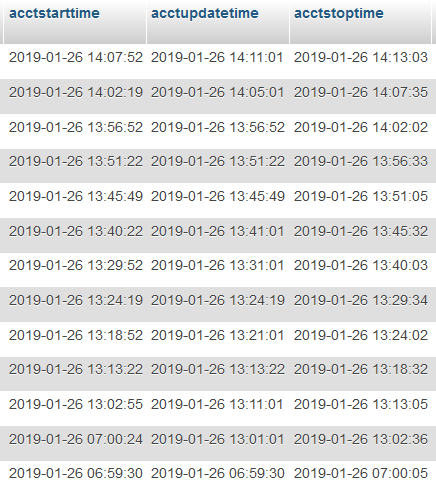
user6761 2019-01-22 18:56:33 2019-01-23 11:02:36 31.13.144.106 172.16.23.178 User-Request 154.018 21.821
После отключения в 11:02
В журнале роутера ошибка:
Jan 23 13:54:42ndmIpSec::Configurator: IKE message parsing error for crypto map «L2TP0».
Jan 23 13:54:42ndmIpSec::Configurator: (possibly because of wrong pre-shared key).
Jan 23 13:54:42ndmIpSec::Configurator: crypto map «L2TP0» active IKE SA: 0, active CHILD SA: 0.
Jan 23 13:54:42ndmIpSec::Configurator: fallback peer is not defined for crypto map «L2TP0», retry.
Последнее редактирование: 3 года 8 мес. назад пользователем admin.
Пожалуйста Войти или Регистрация, чтобы присоединиться к беседе.
4 года 2 нед. назад #3587
от admin
possibly because of wrong pre-shared key — Скорее всего ошибка в ключе или его вообще нет. Он должен быть vpnki
Пожалуйста Войти или Регистрация, чтобы присоединиться к беседе.
4 года 2 нед. назад #3588
от ddd0251
Спасибо.
Пересохранили настройки, все поднялось.
Пожалуйста Войти или Регистрация, чтобы присоединиться к беседе.
4 года 2 нед. назад #3589
от admin
Хорошо, буду рад кликам по баннерам ![]()
Пожалуйста Войти или Регистрация, чтобы присоединиться к беседе.
4 года 2 нед. назад #3594
от ddd0251
Снова нет соединения. user6761
Настройки пересохраняли.
Jan 26 17:41:54ndmNetwork::Interface::Base: «L2TP0»: interface is up.
Jan 26 17:41:57l2tp[1717]Plugin pppol2tp.so loaded.
Jan 26 17:41:57l2tp[1717]pppd 2.4.4-4 started by root, uid 0
Jan 26 17:41:57ndmNetwork::Interface::L2TP: «L2TP0»: added host route to 193.232.49.4 via 192.168.8.1.
Jan 26 17:41:57pppd_L2TP0l2tp_control v2.02
Jan 26 17:41:57pppd_L2TP0remote host: 193.232.49.4
Jan 26 17:41:57pppd_L2TP0local bind: 192.168.8.100
Jan 26 17:41:59pppd_L2TP0timeout of sccrp, retry sccrq, try: 1
Jan 26 17:42:01pppd_L2TP0timeout of sccrp, retry sccrq, try: 2
Jan 26 17:42:03pppd_L2TP0timeout of sccrp, retry sccrq, try: 3
Jan 26 17:42:05pppd_L2TP0timeout of sccrp, retry sccrq, try: 4
Jan 26 17:42:07pppd_L2TP0timeout of sccrp, retry sccrq, try: 5
Jan 26 17:42:07pppd_L2TP0sccrq failed, fatal
Jan 26 17:42:16pppd_L2TP0control init failed
Jan 26 17:42:16pppd_L2TP0Couldn’t get channel number: Bad file descriptor
Jan 26 17:42:16pppd_L2TP0Exit.
Jan 26 17:42:16ndmService: «L2TP0»: unexpectedly stopped.
Jan 26 17:42:16ndmNetwork::Interface::Base: «L2TP0»: interface is up.
Jan 26 17:42:19l2tp[1735]Plugin pppol2tp.so loaded.
Jan 26 17:42:19l2tp[1735]pppd 2.4.4-4 started by root, uid 0
Jan 26 17:42:19ndmNetwork::Interface::L2TP: «L2TP0»: added host route to 193.232.49.4 via 192.168.8.1.
Jan 26 17:42:19pppd_L2TP0l2tp_control v2.02
Jan 26 17:42:19pppd_L2TP0remote host: 193.232.49.4
Jan 26 17:42:19pppd_L2TP0local bind: 192.168.8.100
Jan 26 17:42:25pppd_L2TP0timeout of sccrp, retry sccrq, try: 1
Jan 26 17:42:27pppd_L2TP0timeout of sccrp, retry sccrq, try: 2
Jan 26 17:42:29pppd_L2TP0timeout of sccrp, retry sccrq, try: 3
Jan 26 17:42:31pppd_L2TP0timeout of sccrp, retry sccrq, try: 4
Jan 26 17:42:33pppd_L2TP0timeout of sccrp, retry sccrq, try: 5
Jan 26 17:42:33pppd_L2TP0sccrq failed, fatal
Jan 26 17:42:38pppd_L2TP0control init failed
Jan 26 17:42:38pppd_L2TP0Couldn’t get channel number: Bad file descriptor
Jan 26 17:42:38pppd_L2TP0Exit.
Jan 26 17:42:38ndmService: «L2TP0»: unexpectedly stopped.
Пожалуйста Войти или Регистрация, чтобы присоединиться к беседе.
4 года 2 нед. назад #3595
от admin
Мне не очень понятен этот лог…
Сегодня вообще у user6761 очень странное поведение начиная с 13-00 по Мск.
Скажите:
1. Не проводили ли вы с 13 часов какие-либо изменения?
2. Судя по логу маршрутизатор ругается на таймаут протокола L2TP. Это порт UDP 1701… нет ли какого-либо межсетевого экрана по дороге, который может блокировать этот порт? Или сам Кинетик, например?
3. Перезагружали ли маршрутизатор?
Пожалуйста Войти или Регистрация, чтобы присоединиться к беседе.
- ВОПРОСЫ
- Форум техподдержки
- Техническая поддержка / Support
-
По работе туннелей и маршрутизации / VPN tuns & routing
- Не соединяется туннель по L2TPIPSec Keenetic 4G III
Время создания страницы: 0.090 секунд
Contents
Introduction
This document contains the most common solutions to IPsec VPN problems. These solutions come directly from service requests that the Cisco Technical Support have solved. Many of these solutions can be implemented prior to the in-depth troubleshooting of an IPsec VPN connection. As a result, this document provides a checklist of common procedures to try before you begin to troubleshoot a connection and call Cisco Technical Support.
If you need configuration example documents for the site-to-site VPN and remote access VPN, refer to the Remote Access VPN, Site to Site VPN (L2L) with PIX, Site to Site VPN (L2L) with IOS, and Site to Site VPN (L2L) with VPN3000 sections of Configuration Examples and TechNotes.
Note: Even though the configuration examples in this document are for use on routers and security appliances, nearly all of these concepts are also applicable to the VPN 3000 concentrator.
Note: Refer to IP Security Troubleshooting — Understanding and Using debug Commands to provide an explanation of common debug commands that are used to troubleshoot IPsec issues on both the Cisco IOS® Software and PIX.
Note: ASA/PIX will not pass multicast traffic over IPsec VPN tunnels.
Note: You can look up any command used in this document with the Command Lookup Tool (registered customers only).
 Warning: Many of the solutions presented in this document can lead to a temporary loss of all IPsec VPN connectivity on a device. It is recommended that these solutions be implemented with caution and in accordance with your change control policy.
Prerequisites
Requirements
Cisco recommends that you have knowledge of IPsec VPN configuration on these Cisco devices:
-
Cisco PIX 500 Series Security Appliance
-
Cisco ASA 5500 Series Security Appliance
-
Cisco IOS Routers
-
Cisco VPN 3000 Series Concentrators (Optional)
Components Used
The information in this document is based on these software and hardware versions:
-
Cisco ASA 5500 Series Security Appliance
-
Cisco PIX 500 Series Security Appliance
-
Cisco IOS
The information in this document was created from the devices in a specific lab environment. All of the devices used in this document started with a cleared (default) configuration. If your network is live, make sure that you understand the potential impact of any command.
Conventions
Refer to Cisco Technical Tips Conventions for more information on document conventions.
IPsec VPN Configuration Does Not Work
Problem
A recently configured or modified IPsec VPN solution does not work.
A current IPsec VPN configuration no longer works.
Solutions
This section contains solutions to the most common IPsec VPN problems. Although they are not listed in any particular order, these solutions can be used as a checklist of items to verify or try before you engage in in-depth troubleshooting and call the TAC. All of these solutions come directly from TAC service requests and have resolved numerous customer issues.
-
Enable NAT-Traversal (#1 RA VPN Issue)
-
Test Connectivity Properly
-
Enable ISAKMP
-
Enable/Disable PFS
-
Clear Old or Existing Security Associations (Tunnels)
-
Verify ISAKMP Lifetime
-
Enable or Disable ISAKMP Keepalives
-
Re-Enter or Recover Pre-Shared-Keys
-
Mismatched Pre-shared Key
-
Remove and Re-apply Crypto Maps
-
Verify that sysopt Commands are Present (PIX/ASA Only)
-
Verify the ISAKMP Identity
-
Verify Idle/Session Timeout
-
Verify that ACLs are Correct and are Binded to Crypto Map
-
Verify the ISAKMP Policies
-
Verify that Routing is Correct
-
Verify that Transform-Set is Correct
-
Verify Crypto Map Sequence Numbers and Name
-
Verify the Peer IP Address is Correct
-
Verify the Tunnel Group and Group Names
-
Disable XAUTH for L2L Peers
-
VPN Pool Getting Exhausted
-
Issues with latency for VPN client traffic
Note: Some of the commands in these sections have been brought down to a second line due to spatial considerations.
Enable NAT-Traversal (#1 RA VPN Issue)
NAT-Traversal or NAT-T allows VPN traffic to pass through NAT or PAT devices, such as a Linksys SOHO router. If NAT-T is not enabled, VPN Client users often appear to connect to the PIX or ASA without a problem, but they are unable to access the internal network behind the security appliance.
If you do not enable the NAT-T in the NAT/PAT Device, you can receive the regular translation creation failed for protocol 50 src inside:10.0.1.26 dst outside:10.9.69.4 error message in the PIX/ASA.
Similarly, if you are unable to do simultaneous login from the same IP address, the Secure VPN connection terminated locally by client. Reason 412: The remote peer is no longer responding. error message appears. Enable NAT-T in the head end VPN device in order to resolve this error.
Note: With Cisco IOS Software Release 12.2(13)T and later, NAT-T is enabled by default in Cisco IOS.
Here is the command to enable NAT-T on a Cisco Security Appliance. The 20 in this example is the keepalive time (default).
PIX/ASA 7.1 and earlier
pix(config)#isakmp nat-traversal 20
PIX/ASA 7.2(1) and later
securityappliance(config)#crypto isakmp nat-traversal 20
The clients need to be modified as well in order for it to work.
In Cisco VPN Client, choose to Connection Entries and click Modify. It opens a new window where you have to choose the Transport tab. Under this tab, choose Enable Transparent Tunneling and the IPSec over UDP ( NAT / PAT ) radio button. Then click Save and test the connection.
Note: This command is the same for both PIX 6.x and PIX/ASA 7.x.
Note: It is important to allow the UDP 4500 for NAT-T, UDP 500 and ESP ports by the configuration of an ACL because the PIX/ASA acts as a NAT device. Refer to Configuring an IPsec Tunnel through a Firewall with NAT for more information in order to learn more about the ACL configuration in PIX/ASA.
VPN Concentrator
Choose Configuration > Tunneling and Security > IPSEC > NAT Transparency > Enable: IPsec over NAT-T in order to enable NAT-T on the VPN Concentrator.
Note: NAT-T also lets multiple VPN clients to connect through a PAT device at same time to any head end whether it is PIX, Router or Concentrator.
Test Connectivity Properly
Ideally, VPN connectivity is tested from devices behind the endpoint devices that do the encryption, yet many users test VPN connectivity with the ping command on the devices that do the encryption. While the ping generally works for this purpose, it is important to source your ping from the correct interface. If the ping is sourced incorrectly, it can appear that the VPN connection has failed when it really works. Take this scenario as an example:
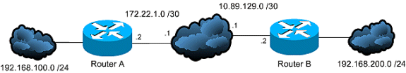
Router A crypto ACL
access-list 110 permit ip 192.168.100.0 0.0.0.255 192.168.200.0 0.0.0.255
Router B crypto ACL
access-list 110 permit ip 192.168.200.0 0.0.0.255 192.168.100.0 0.0.0.255
In this situation, a ping must be sourced from the «inside» network behind either router. This is because the crypto ACLs are only configured to encrypt traffic with those source addresses. A ping sourced from the Internet-facing interfaces of either router are not encrypted. Use the extended options of the ping command in privileged EXEC mode to source a ping from the «inside» interface of a router:
routerA#ping
Protocol [ip]:
Target IP address: 192.168.200.10
Repeat count [5]:
Datagram size [100]:
Timeout in seconds [2]:
Extended commands [n]: y
Source address or interface: 192.168.100.1
Type of service [0]:
Set DF bit in IP header? [no]:
Validate reply data? [no]:
Data pattern [0xABCD]:
Loose, Strict, Record, Timestamp, Verbose[none]:
Sweep range of sizes [n]:
Type escape sequence to abort.
Sending 5, 100-byte ICMP Echos to 192.168.200.1, timeout is 2 seconds:
Packet sent with a source address of 192.168.100.1
!!!!!
Success rate is 100 percent (5/5), round-trip min/avg/max = ½/4 ms
Imagine that the routers in this diagram have been replaced with PIX or ASA security appliances. The ping used to test connectivity can also be sourced from the inside interface with the inside keyword:
securityappliance#ping inside 192.168.200.10
Type escape sequence to abort.
Sending 5, 100-byte ICMP Echos to 192.168.200.10, timeout is 2 seconds:
!!!!!
Success rate is 100 percent (5/5), round-trip min/avg/max = 1/1/1 ms
Note: It is not recommended that you target the inside interface of a security appliance with your ping. If you must target the inside interface with your ping, you must enable management-access on that interface, or the appliance does not reply.
securityappliance(config)#management-access inside
Note: When a problem exist with the connectivity, even phase 1 of VPN does not come up. On the ASA, if connectivity fails, the SA output is similar to this example, which indicates possibly an incorrect crypto peer configuration and/or incorrect ISAKMP proposal configuration:
Router#show crypto isakmp sa

1   IKE Peer: XX.XX.XX.XX
    Type    : L2L             Role    : initiator
    Rekey   : no              State   : MM_WAIT_MSG2
Note: The state could be from MM_WAIT_MSG2 to MM_WAIT_MSG5, which denotes failure of concerned state exchange in main mode (MM).
Note: Crypto SA output when the phase 1 is up is similar to this example:
Router#show crypto isakmp sa

1   IKE Peer: XX.XX.XX.XX
    Type    : L2L             Role    : initiator
    Rekey   : no              State   : MM_ACTIVE
Enable ISAKMP
If there is no indication that an IPsec VPN tunnel comes up at all, it possibly is due to the fact that ISAKMP has not been enabled. Be sure that you have enabled ISAKMP on your devices. Use one of these commands to enable ISAKMP on your devices:
-
Cisco IOS
router(config)#crypto isakmp enable
-
Cisco PIX 7.1 and earlier (replace outside with your desired interface)
pix(config)#isakmp enable outside
-
Cisco PIX/ASA 7.2(1) and later (replace outside with your desired interface)
securityappliance(config)#crypto isakmp enable outside
You can also get this error when you enable the ISAKMP on the outside interface:
UDP: ERROR - socket <unknown> 62465 in used
ERROR: IkeReceiverInit, unable to bind to port
The cause of the error can be that the Client behind ASA/PIS gets PAT’d to udp port 500 before isakmp can be enabled on the interface. Once that PAT translation is removed (clear xlate), the isakmp is able to be enabled.
Note: Always make sure that UDP 500 and 4500 port numbers are reserved for the negotiation of ISAKMP connections with the peer.
Note: When the ISAKMP is not enabled on the interface, the VPN client shows an error message similar to this message:
Secure VPN connection terminated locally by client.
Reason 412: The remote peer is no longer responding
Note: In order to resolve this error, enable the ISAKMP on the crypto interface of the VPN gateway.
Enable/Disable PFS
In IPsec negotiations, Perfect Forward Secrecy (PFS) ensures that each new cryptographic key is unrelated to any previous key. Either enable or disable PFS on both the tunnel peers; otherwise, the LAN-to-LAN (L2L) IPsec tunnel is not established in the PIX/ASA/IOS router.
PIX/ASA:
PFS is disabled by default. In order to enable PFS, use the pfs command with the enable keyword in group-policy configuration mode. In order to disable PFS, enter the disable keyword.
hostname(config-group-policy)#pfs {enable | disable}
In order to remove the PFS attribute from the running configuration, enter the no form of this command. A group policy can inherit a value for PFS from another group policy. Enter the no form of this command in order to prevent inheriting a value.
hostname(config-group-policy)#no pfs
IOS Router:
In order to specify that IPsec must ask for PFS when new Security Associations are requested for this crypto map entry, or that IPsec requires PFS when it receives requests for new Security Associations, use the set pfs command in crypto map configuration mode. In order to specify that IPsec must not request PFS, use the no form of this command. By default, PFS is not requested. If no group is specified with this command, group1 is used as the default.
set pfs [group1 | group2]
no set pfs
For the set pfs command:
-
group1 —Specifies that IPsec must use the 768-bit Diffie-Hellman prime modulus group when the new Diffie-Hellman exchange is performed.
-
group2 —Specifies that IPsec must use the 1024-bit Diffie-Hellman prime modulus group when the new Diffie-Hellman exchange is performed.
Example:
Router(config)#crypto map map 10 ipsec-isakmp
Router(config-crypto-map)#set pfs group2
Note: Perfect Forward Secrecy (PFS) is Cisco proprietary and is not supported on third party devices.
Clear Old or Existing Security Associations (Tunnels)
If this error message occurs in the IOS Router, the problem is that the SA has either expired or been cleared. The remote tunnel end device does not know that it uses the expired SA to send a packet (not a SA establishment packet). When a new SA has been established, the communication resumes, so initiate the interesting traffic across the tunnel to create a new SA and re-establish the tunnel.
%CRYPTO-4-IKMP_NO_SA: IKE message from x.x.x.x has no SA
If you clear ISAKMP (Phase I) and IPsec (Phase II) security associations (SAs), it is the simplest and often the best solution to resolve IPsec VPN problems.
If you clear SAs, you can frequently resolve a wide variety of error messages and strange behaviors without the need to troubleshoot. While this technique can easily be used in any situation, it is almost always a requirement to clear SAs after you change or add to a current IPsec VPN configuration. Moreover, while it is possible to clear only specific security associations, the most benefit can come from when you clear SAs globally on the device.
Note: Once the Security Associations have been cleared, it can be necessary to send traffic across the tunnel to re-establish them.
Warning: Unless you specify which security associations to clear, the commands listed here can clear all security associations on the device. Proceed with caution if other IPsec VPN tunnels are in use.
-
View Security Associations before you clear them
-
Cisco IOS
router#show crypto isakmp sa
router#show crypto ipsec sa
-
Cisco PIX/ASA Security Appliances
securityappliance#show crypto isakmp sa
securityappliance#show crypto ipsec sa
Note: These commands are the same for both Cisco PIX 6.x and PIX/ASA 7.x
-
-
Clear Security Associations. Each command can be entered as shown in bold or entered with the options shown with them.
-
Cisco IOS
-
ISAKMP (Phase I)
router#clear crypto isakmp ?
  <0 - 32766>  connection id of SA
  <cr>
-
IPsec (Phase II)
router#clear crypto sa ?
  counters  Reset the SA counters
  map       Clear all SAs for a given crypto map
  peer      Clear all SAs for a given crypto peer
  spi       Clear SA by SPI
  <cr>
-
-
Cisco PIX/ASA Security Appliances
-
ISAKMP (Phase I)
securityappliance#clear crypto isakmp sa
-
IPsec (Phase II)
security appliance#clear crypto ipsec sa ?

  counters  Clear IPsec SA counters
  entry     Clear IPsec SAs by entry
  map       Clear IPsec SAs by map
  peer      Clear IPsec SA by peer
  <cr>
-
-
Verify ISAKMP Lifetime
If the users are frequently disconnected across the L2L tunnel, the problem can be the lesser lifetime configured in ISAKMP SA. If any discrepancy occurs in the ISAKMP lifetime, you can receive the %PIX|ASA-5-713092: Group = x.x.x.x, IP = x.x.x.x, Failure during phase 1 rekeying attempt due to collision error message in PIX/ASA. For FWSM, you can receive the %FWSM-5-713092: Group = x.x.x.x, IP = x.x.x.x, Failure during phase 1 rekeying attempt due to collision error message. Configure the same value in both the peers in order to fix it.
The default is 86,400 seconds or 24 hours. As a general rule, a shorter lifetime provides more secure ISAKMP negotiations (up to a point), but, with shorter lifetimes, the security appliance sets up future IPsec SAs more quickly.
A match is made when both policies from the two peers contain the same encryption, hash, authentication, and Diffie-Hellman parameter values, and when the policy of the remote peer specifies a lifetime less than or equal to the lifetime in the compared policy. If the lifetimes are not identical, the shorter lifetime—from the policy of the remote peer—is used. If no acceptable match is found, the IKE refuses negotiation, and the IKE SA is not established.
Specify the SA lifetime. This examples sets a lifetime of 4 hours (14400 seconds). The default is 86400 seconds (24 hours).
PIX/ASA
hostname(config)#isakmp policy 2 lifetime 14400
IOS Router
R2(config)#crypto isakmp policy 10
R2(config-isakmp)#lifetime 86400
If the maximum configured lifetime is exceeded, you receive this error message when the VPN connection is terminated:
Secure VPN Connection terminated locally by the Client. Reason 426: Maximum Configured Lifetime Exceeded.
In order to resolve this error message, set the lifetime value to 0 in order to set the lifetime of an IKE security association to infinity. The VPN will always be connection and will not terminate.
hostname(config)#isakmp policy 2 lifetime 0
You can also disable re-xauth in the group-policy in order to resolve the issue.
Enable or Disable ISAKMP Keepalives
If you configure ISAKMP keepalives, it helps prevent sporadically dropped LAN-to-LAN or Remote Access VPN, which includes VPN clients, tunnels and the tunnels that are dropped after a period of inactivity. This feature lets the tunnel endpoint monitor the continued presence of a remote peer and report its own presence to that peer. If the peer becomes unresponsive, the endpoint removes the connection. In order for ISAKMP keepalives to work, both VPN endpoints must support them.
-
Configure ISAKMP keepalives in Cisco IOS with this command:
router(config)#crypto isakmp keepalive 15
-
Use these commands to configure ISAKMP keepalives on the PIX/ASA Security Appliances:
-
Cisco PIX 6.x
pix(config)#isakmp keepalive 15
-
Cisco PIX/ASA 7.x and later, for the tunnel group named 10.165.205.222
securityappliance(config)#tunnel-group 10.165.205.222
   ipsec-attributes

securityappliance(config-tunnel-ipsec)#isakmp keepalive
   threshold 15 retry 10
In some situations, it is necessary to disable this feature in order to solve the problem, for example, if the VPN Client is behind a Firewall that prevents DPD packets.
Cisco PIX/ASA 7.x and later, for the tunnel group named 10.165.205.222
Disables IKE keepalive processing, which is enabled by default.
securityappliance(config)#tunnel-group 10.165.205.222
   ipsec-attributes

securityappliance(config-tunnel-ipsec)#isakmp keepalive disable
Disable Keepalive for Cisco VPN Client 4.x
Choose %System Root% > Program Files > Cisco Systems >VPN Client > Profiles on the Client PC that experiences the issue in order to disable IKE keepalive, and edit the PCF file , where applicable, for the connection.
Change the ‘ForceKeepAlives=0’ (default) to ‘ForceKeepAlives=1’.
-
Note: Keepalives are Cisco proprietary and are not supported by third party devices.
Re-Enter or Recover Pre-Shared-Keys
In many cases, a simple typo can be to blame when an IPsec VPN tunnel does not come up. For example, on the security appliance, pre-shared keys become hidden once they are entered. This obfuscation makes it impossible to see if a key is incorrect.Be certain that you have entered any pre-shared-keys correctly on each VPN endpoint. Re-enter a key to be certain that it is correct; this is a simple solution that can help avoid in-depth troubleshooting.
In Remote Access VPN, check that the valid group name and preshared key are entered in the CiscoVPN Client. You can face this error if the group name/ preshared key are not matched between the VPN Client and the head-end device.
 1 12:41:51.900 02/18/06 Sev=Warning/3 IKE/0xE3000056
 The received HASH payload cannot be verified
 2 12:41:51.900 02/18/06 Sev=Warning/2 IKE/0xE300007D
Hash verification failed
3      14:37:50.562  10/05/06  Sev=Warning/2 IKE/0xE3000099
Failed to authenticate peer (Navigator:904)
4      14:37:50.593  10/05/06  Sev=Warning/2 IKE/0xE30000A5
Unexpected SW error occurred while processing Aggressive Mode
negotiator:(Navigator:2202)
5      14:44:15.937  10/05/06  Sev=Warning/2 IKE/0xA3000067
Received Unexpected InitialContact Notify (PLMgrNotify:888)
6      14:44:36.578  10/05/06  Sev=Warning/3 IKE/0xE3000056
The received HASH payload cannot be verified
7      14:44:36.593  10/05/06  Sev=Warning/2 IKE/0xE300007D
Hash verification failed... may be configured with invalid group password.
8      14:44:36.609  10/05/06  Sev=Warning/2 IKE/0xE3000099
Failed to authenticate peer (Navigator:904)
9      14:44:36.640  10/05/06  Sev=Warning/2 IKE/0xE30000A5
Unexpected SW error occurred while processing Aggressive Mode
negotiator:(Navigator:2202)
You can also recover a pre-shared key without any configuration changes on the PIX/ASA security appliance. Refer to PIX/ASA 7.x: Pre-shared Key Recovery.
Warning: If you remove crypto-related commands, you are likely to bring down one or all of your VPN tunnels. Use these commands with caution and refer to the change control policy of your organization before you follow these steps.
-
Use these commands to remove and re-enter the pre-shared-key secretkey for the peer 10.0.0.1 or the group vpngroup in IOS:
-
Cisco LAN-to-LAN VPN
router(config)#no crypto isakmp key secretkey
   address 10.0.0.1
router(config)#crypto isakmp key secretkey
   address 10.0.0.1
-
Cisco Remote Access VPN
router(config)#crypto isakmp client configuration
   group vpngroup
router(config-isakmp-group)#no key secretkey
router(config-isakmp-group)#key secretkey
-
-
Use these commands to remove and re-enter the pre-shared-key secretkey for the peer 10.0.0.1 on PIX/ASA Security Appliances:
-
Cisco PIX 6.x
pix(config)#no isakmp key secretkey address 10.0.0.1
pix(config)#isakmp key secretkey address 10.0.0.1
-
Cisco PIX/ASA 7.x and later
securityappliance(config)#tunnel-group 10.0.0.1
   ipsec-attributes
securityappliance(config-tunnel-ipsec)#no pre-shared-key
securityappliance(config-tunnel-ipsec)#pre-shared-key
   secretkey
-
Mismatched Pre-shared Key
The initiation of VPN Tunnel gets disconnected. This issue might occur because of a mismatched pre-shared-key during the phase I negotiations.
The MM_WAIT_MSG_6 message in the show crypto isakmp sa command indicates a mismatched pre-shared-key as shown in this example:
ASA#show crypto isakmp sa

Active SA: 1
Rekey SA: 0 (A tunnel will report 1 Active and 1 Rekey SA during rekey)
Total IKE SA: 1

1         IKE Peer: 10.7.13.20
             Type : L2L                                 Role : initiator
             Rekey : no                                 State : MM_WAIT_MSG_6
In order to resolve this issue, re-enter the pre-shared key in both appliances; the pre-shared-key must be unique and matched. See Re-Enter or Recover Pre-Shared-Keys for more information.
Remove and Re-apply Crypto Maps
When you clear security associations, and it does not resolve an IPsec VPN issue, remove and reapply the relevant crypto map in order to resolve a wide variety of issues that includes intermittent dropping of VPN tunnel and failure of some VPN sites to come up.
Warning: If you remove a crypto map from an interface, it definitely brings down any IPsec tunnels associated with that crypto map. Follow these steps with caution and consider the change control policy of your organization before you proceed.
-
Use these commands to remove and replace a crypto map in Cisco IOS:
Begin with the removal of the crypto map from the interface. Use the no form of the crypto map command.
router(config-if)#no crypto map mymap
Continue to use the no form to remove an entire crypto map.
router(config)#no crypto map mymap 10
Replace the crypto map on interface Ethernet0/0 for the peer 10.0.0.1. This example shows the minimum required crypto map configuration:
router(config)#crypto map mymap 10 ipsec-isakmp
router(config-crypto-map)#match address 101
router(config-crypto-map)#set transform-set mySET
router(config-crypto-map)#set peer 10.0.0.1
router(config-crypto-map)#exit
router(config)#interface ethernet0/0
router(config-if)#crypto map mymap
-
Use these commands to remove and replace a crypto map on the PIX or ASA:
Begin with the removal of the crypto map from the interface. Use the no form of the crypto map command.
securityappliance(config)#no crypto map mymap interface outside
Continue to use the no form to remove the other crypto map commands.
securityappliance(config)#no crypto map mymap 10 match
   address 101
securityappliance(config)#no crypto map mymap set
   transform-set mySET
securityappliance(config)#no crypto map mymap set
   peer 10.0.0.1
Replace the crypto map for the peer 10.0.0.1. This example shows the minimum required crypto map configuration:
securityappliance(config)#crypto map mymap 10 ipsec-isakmp
securityappliance(config)#crypto map mymap 10
   match address 101
securityappliance(config)#crypto map mymap 10 set
   transform-set mySET
securityappliance(config)#crypto map mymap 10 set
   peer 10.0.0.1
securityappliance(config)#crypto map mymap interface outside
Note: If you remove and reapply the crypto map, this also resolves the connectivity issue if the IP address of head end has been changed.
Verify that sysopt Commands are Present (PIX/ASA Only)
The commands sysopt connection permit-ipsec and sysopt connection permit-vpn allow packets from an IPsec tunnel and their payloads to bypass interface ACLs on the security appliance. IPsec tunnels that are terminated on the security appliance are likely to fail if one of these commands is not enabled.
In Security Appliance Software Version 7.0 and earlier, the relevant sysopt command for this situation is sysopt connection permit-ipsec.
In Security Appliance Software Version 7.1(1) and later, the relevant sysopt command for this situation is sysopt connection permit-vpn.
In PIX 6.x, this functionality is disabled by default. With PIX/ASA 7.0(1) and later, this functionality is enabled by default. Use these show commands to determine if the relevant sysopt command is enabled on your device:
-
Cisco PIX 6.x
pix# show sysopt no sysopt connection timewait sysopt connection tcpmss 1380 sysopt connection tcpmss minimum 0 no sysopt nodnsalias inbound no sysopt nodnsalias outbound no sysopt radius ignore-secret no sysopt uauth allow-http-cache no sysopt connection permit-ipsec !--- sysopt connection permit-ipsec is disabled no sysopt connection permit-pptp no sysopt connection permit-l2tp no sysopt ipsec pl-compatible -
Cisco PIX/ASA 7.x
securityappliance# show running-config all sysopt
no sysopt connection timewait
sysopt connection tcpmss 1380
sysopt connection tcpmss minimum 0
no sysopt nodnsalias inbound
no sysopt nodnsalias outbound
no sysopt radius ignore-secret
sysopt connection permit-vpn

!--- sysopt connection permit-vpn is enabled !--- This device is running 7.2(2)
Use these commands in order to enable the correct sysopt command for your device:
-
Cisco PIX 6.x and PIX/ASA 7.0
pix(config)#sysopt connection permit-ipsec
-
Cisco PIX/ASA 7.1(1) and later
securityappliance(config)#sysopt connection permit-vpn
Note: If you do not wish to use the sysopt connection command, then you must explicitly permit the required traffic, which is interesting traffic from source to destination, for example, from LAN of remote device to LAN of local device and «UDP port 500» for outside interface of remote device to outside interface of local device, in outside ACL.
Verify the ISAKMP Identity
If the IPsec VPN tunnel has failed within the IKE negotiation, the failure can be due to either the PIX or the inability of its peer to recognize the identity of its peer. When two peers use IKE to establish IPsec security associations, each peer sends its ISAKMP identity to the remote peer. It sends either its IP address or host name dependent upon how each has its ISAKMP identity set. By default, the ISAKMP identity of the PIX Firewall unit is set to the IP address. As a general rule, set the security appliance and the identities of its peers in the same way to avoid an IKE negotiation failure.
In order to set the Phase 2 ID to be sent to the peer, use the isakmp identity command in global configuration mode
crypto isakmp identity address

!--- If the RA or L2L (site-to-site) VPN tunnels connect !--- with pre-shared key as authentication type
OR
crypto isakmp identity auto

!--- If the RA or L2L (site-to-site) VPN tunnels connect !--- with ISAKMP negotiation by connection type; IP address for !--- preshared key or cert DN for certificate authentication.
OR
crypto isakmp identity hostname

!--- Uses the fully-qualified domain name of !--- the host exchanging ISAKMP identity information (default). !--- This name comprises the hostname and the domain name.
VPN tunnel fails to come up after moving configuration from PIX to ASA using the PIX/ASA configuration migration tool; these messages appear in the log:
[IKEv1]: Group = x.x.x.x, IP = x.x.x.x, Stale PeerTblEntry found, removing! [IKEv1]: Group = x.x.x.x, IP = x.x.x.x, Removing peer from correlator table failed, no match! [IKEv1]: Group = x.x.x.x, IP = x.x.x.x, construct_ipsec_delete(): No SPI to identify Phase 2 SA! [IKEv1]: Group = x.x.x.x, IP = x.x.x.x, Removing peer from correlator table failed, no match!
This issue happens since PIX by default is set to identify the connection as hostname where the ASA identifies as IP. In order to resolve this issue, use the crypto isakmp identity command in global configuration mode as shown below:
crypto isakmp identity hostname


!--- Use the fully-qualified domain name of !--- the host exchanging ISAKMP identity information (default). !--- This name comprises the hostname and the domain name.
When you receive the Received an un-encrypted INVALID_COOKIE error message, issue the crypto isakmp identity address command in order to resolve the issue.
Note: The isakmp identity command was deprecated from the software version 7.2(1). Refer to the Cisco Security Appliance Command Reference, Version 7.2 for more information.
Verify Idle/Session Timeout
If the idle timeout is set to 30 minutes (default), it means that it drops the tunnel after 30 minutes of no traffic passes through it. The VPN client gets disconnected after 30 minutes regardless of the setting of idle timeout and encounters the PEER_DELETE-IKE_DELETE_UNSPECIFIED error.
Configure idle timeout and session timeout as none in order to make the tunnel always up, and so that the tunnel is never dropped even when using third party devices.
PIX/ASA 7.x and later
Enter the vpn-idle-timeout command in group-policy configuration mode or in username configuration mode in order to configure the user timeout period:
hostname(config)#group-policy DfltGrpPolicy attributes
hostname(config-group-policy)#vpn-idle-timeout none
Configure a maximum amount of time for VPN connections with the vpn-session-timeout command in group-policy configuration mode or in username configuration mode:
hostname(config)#group-policy DfltGrpPolicy attributes
hostname(config-group-policy)#vpn-session-timeout none
Note: When you have tunnel-all configured, you do not need to configure idle-timeout because, even if you configure VPN-idle timeout, it will not work because all traffic is going through the tunnel (since tunnel-all is configured). Therefore, the interesting traffic (or even the traffic generated by the PC) will be interesting and will not let Idle-timeout come into action.
Cisco IOS Router
Use the crypto ipsec security-association idle-time command in global configuration mode or crypto map configuration mode in order to configure the IPsec SA idle timer. By default IPsec SA idle timers are disabled.
crypto ipsec security-association idle-time
seconds
Time is in seconds, which the idle timer allows an inactive peer to maintain an SA. Valid values for the seconds argument range from 60 to 86400.
Verify that ACLs are Correct and Binded to Crypto Map
There are two access lists used in a typical IPsec VPN configuration. One access list is used to exempt traffic that is destined for the VPN tunnel from the NAT process. The other access list defines what traffic to encrypt; this includes a crypto ACL in a LAN-to-LAN setup or a split-tunneling ACL in a Remote Access configuration. When these ACLs are incorrectly configured or missing, traffic might only flow in one direction across the VPN tunnel, or it might not be sent across the tunnel at all.
Note: Make sure to bind the crypto ACL with crypto map by using the crypto map match address command in global configuration mode.
Be sure that you have configured all of the access lists necessary to complete your IPsec VPN configuration and that those access lists define the correct traffic. This list contains simple things to check when you suspect that an ACL is the cause of problems with your IPsec VPN.
-
Make sure that your NAT Exemption and crypto ACLs specify the correct traffic.
-
If you have multiple VPN tunnels and multiple crypto ACLs, make sure that those ACLs do not overlap.
Note: On VPN concentrator, you might see a log like this:
Tunnel Rejected: IKE peer does not match remote peer as defined in L2L policy
In order to avoid this message and in order to bring the tunnel up, make sure that the crypto ACLs do not overlap and the same interesting traffic is not used by any other configured VPN tunnel.
-
Do not use ACLs twice. Even if your NAT Exemption ACL and crypto ACL specify the same traffic, use two different access lists.
-
For remote access configuration, do not use access-list for interesting traffic with the dynamic crypto map. This can cause the VPN client to be unable to connect to the head end device. If you mistakenly configured the crypto ACL for Remote access VPN, you can get the %ASA-3-713042: IKE Initiator unable to find policy: Intf 2 error message.
Note: If this is a VPN site-to-site tunnel, make sure to match the access list with the peer. They must be in reverse order on the peer.
Refer to PIX/ASA 7.x and Cisco VPN Client 4.x with Windows 2003 IAS RADIUS (Against Active Directory) Authentication Configuration Example for a sample configuration that shows how to set up the remote access VPN connection between a Cisco VPN Client and the PIX/ASA.
-
Make sure that your device is configured to use the NAT Exemption ACL. On a router, this means that you use the route-map command. On the PIX or ASA, this means that you use the nat (0) command. A NAT exemption ACL is required for both LAN-to-LAN and Remote Access configurations.
-
Here, an IOS router is configured to exempt traffic that is sent between 192.168.100.0 /24 and 192.168.200.0 /24 or 192.168.1.0 /24 from NAT. Traffic destined for anywhere else is subject to NAT overload:
access-list 110 deny ip 192.168.100.0 0.0.0.255
   192.168.200.0 0.0.0.255
access-list 110 deny ip 192.168.100.0 0.0.0.255
   192.168.1.0 0.0.0.255
access-list 110 permit ip 192.168.100.0 0.0.0.255 any

route-map nonat permit 10
  match ip address 110

ip nat inside source route-map nonat interface FastEthernet0/0 overload
-
Here, a PIX is configured to exempt traffic that is sent between 192.168.100.0 /24 and 192.168.200.0 /24 or 192.168.1.0 /24 from NAT. For example, all other traffic is subject to NAT overload:
access-list noNAT extended permit ip 192.168.100.0
   255.255.255.0 192.168.200.0 255.255.255.0
access-list noNAT extended permit ip 192.168.100.0
   255.255.255.0 192.168.1.0 255.255.255.0

nat (inside) 0 access-list noNAT
nat (inside) 1 0.0.0.0 0.0.0.0

global (outside) 1 interface
Note: NAT exemption ACLs work only with the IP address or IP networks, such as those examples mentioned (access-list noNAT), and must be identical to the crypto map ACLs. The NAT exemption ACLs do not work with the port numbers (for instance, 23, 25, etc.).
Note: In a VOIP environment, where the voice calls between networks are being communicated through the VPN, the voice calls do not work if the NAT 0 ACLs are not properly configured. Before going deep through VOIP troubleshooting, it is suggested to check the VPN connectivity status because the problem could be with misconfiguration of NAT exempt ACLs.
Note: You can get the error message as shown if there is misconfiguration in NAT exemption (nat 0) ACLs.
%PIX-3-305005: No translation group
found for icmp src outside:192.168.100.41 dst
inside:192.168.200.253 (type 8, code 0)
%ASA-3-305005: No translation group found for
udp src Outside:x.x.x.x/p dst Inside:y.y.y.y/p
Note: Incorrect Example:
access-list noNAT extended permit ip 192.168.100.0
   255.255.255.0 192.168.200.0 255.255.255.0 eq 25
If NAT exemption (nat 0) does not work, then try to remove it and issue the NAT 0 command in order for it to work.
-
-
Make sure that your ACLs are not backwards and that they are the right type.
-
Crypto and NAT exemption ACLs for LAN-to-LAN configurations must be written from the perspective of the device on which the ACL is configured. This means that the ACLs must mirror each other. In this example, a LAN-to-LAN tunnel is set up between 192.168.100.0 /24 and 192.168.200.0 /24.

Router A crypto ACL
access-list 110 permit ip 192.168.100.0 0.0.0.255
   192.168.200.0 0.0.0.255
Router B crypto ACL
access-list 110 permit ip 192.168.200.0 0.0.0.255
   192.168.100.0 0.0.0.255
Note: Although it is not illustrated here, this same concept applies to the PIX and ASA Security Appliances, as well.
-
In PIX/ASA, split-tunnel ACLs for Remote Access configurations must be standard access lists that permit traffic to the network to which the VPN clients need access. IOS routers can use extended ACL for split-tunnel.
Note: In the extended access list, to use ‘any’ at the source in the split tunneling ACL is similar to disable split tunneling. Use only the source networks in the extended ACL for split tunneling.
Note: Correct Example:
access-list 140 permit ip 10.1.0.0 0.0.255.255 10.18.0.0 0.0.255.255
Note: Incorrect Example:
access-list 140 permit ip any 10.18.0.0 0.0.255.255
-
Cisco IOS
router(config)#access-list 10 permit ip 192.168.100.0
router(config)#crypto isakmp client configuration group MYGROUP
router(config-isakmp-group)#acl 10
-
Cisco PIX 6.x
pix(config)#access-list 10 permit 192.168.100.0
   255.255.255.0
pix(config)#vpngroup MYGROUP split-tunnel 10
-
Cisco PIX/ASA 7.x
securityappliance(config)#access-list 10 standard
   permit 192.168.100.0 255.255.255.0
securityappliance(config)#group-policy MYPOLICY internal
securityappliance(config)#group-policy MYPOLICY attributes
securityappliance(config-group-policy)#split-tunnel-policy
   tunnelspecified
securityappliance(config-group-policy)#split-tunnel-network-list
   value 10
-
-

This error occurs in ASA 8.3 if the NO NAT ACL is misconfigured or is not configured on ASA:
%ASA-5-305013: Asymmetric NAT rules matched for forward and reverse flows; Connection for udp src outside: x.x.x.x/xxxxx dst inside:x.x.x.x/xx denied due to NAT reverse path failure
In order to resolve this issue, verify the configuration is correct or reconfigure if the settings are incorrect.
NAT exemption configuration in ASA version 8.3 for site-to-site VPN tunnel:
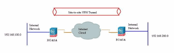
A site-to-site VPN has to be established between HOASA and BOASA with both ASAs using version 8.3. The NAT exemption configuration on HOASA looks similar to this:
object network obj-local
subnet 192.168.100.0 255.255.255.0
object network obj-remote
subnet 192.168.200.0 255.255.255.0
nat (inside,outside) 1 source static obj-local obj-local destination static obj-remote objremote
Verify the ISAKMP Policies
If the IPsec tunnel is not UP, check that the ISAKMP policies match with the remote peers. This ISAKMP policy is applicable to both the Site-to-Site (L2L) and Remote Access IPsec VPN.
If the Cisco VPN Clients or the Site-to-Site VPN are not able establish the tunnel with the remote-end device, check that the two peers contain the same encryption, hash, authentication, and Diffie-Hellman parameter values and when the remote peer policy specifies a lifetime less than or equal to the lifetime in the policy that the initiator sent. If the lifetimes are not identical, the security appliance uses the shorter lifetime. If no acceptable match exists, ISAKMP refuses negotiation, and the SA is not established.
"Error: Unable to remove Peer TblEntry, Removing peer from peer table
failed, no match!"
Here is the detailed log message:
4|Mar 24 2010 10:21:50|713903: IP = X.X.X.X, Error: Unable to remove PeerTblEntry
3|Mar 24 2010 10:21:50|713902: IP = X.X.X.X, Removing peer from peer table failed,
no match!
3|Mar 24 2010 10:21:50|713048: IP = X.X.X.X, Error processing payload: Payload ID: 1
4|Mar 24 2010 10:21:49|713903: IP = X.X.X.X, Information Exchange processing failed
5|Mar 24 2010 10:21:49|713904: IP = X.X.X.X, Received an un-encrypted
NO_PROPOSAL_CHOSEN notify message, dropping
This message usually appears due to mismatched ISAKMP policies or a missing NAT 0 statement.
In addition, this message appears:
Error Message    %PIX|ASA-6-713219: Queueing KEY-ACQUIRE messages to be processed when
P1 SA is complete.
This message indicates that Phase 2 messages are being enqueued after Phase 1 completes. This error message might be due to one of these reasons:
-
Mismatch in phase on any of the peers
-
ACL is blocking the peers from completing phase 1
This message usually comes after the Removing peer from peer table failed, no match! error message.
If the Cisco VPN Client is unable to connect the head-end device, the problem can be the mismatch of ISAKMP Policy. The head-end device must match with one of the IKE Proposals of the Cisco VPN Client.
Note: For the ISAKMP policy and IPsec Transform-set that is used on the PIX/ASA, the Cisco VPN client cannot use a policy with a combination of DES and SHA. If you use DES, you need to use MD5 for the hash algorithm, or you can use the other combinations, 3DES with SHA and 3DES with MD5.
Verify that Routing is Correct
Routing is a critical part of almost every IPsec VPN deployment. Be certain that your encryption devices such as Routers and PIX or ASA Security Appliances have the proper routing information to send traffic over your VPN tunnel. Moreover, if other routers exist behind your gateway device, be sure that those routers know how to reach the tunnel and what networks are on the other side.
One key component of routing in a VPN deployment is Reverse Route Injection (RRI). RRI places dynamic entries for remote networks or VPN clients in the routing table of a VPN gateway. These routes are useful to the device on which they are installed, as well as to other devices in the network because routes installed by RRI can be redistributed through a routing protocol such as EIGRP or OSPF.
-
In a LAN-to-LAN configuration, it is important for each endpoint to have a route or routes to the networks for which it is supposed to encrypt traffic. In this example, Router A must have routes to the networks behind Router B through 10.89.129.2. Router B must have a similar route to 192.168.100.0 /24:
-
The first way to ensure that each router knows the appropriate route(s) is to configure static routes for each destination network. For example, Router A can have these route statements configured:
ip route 0.0.0.0 0.0.0.0 172.22.1.1
ip route 192.168.200.0 255.255.255.0 10.89.129.2
ip route 192.168.210.0 255.255.255.0 10.89.129.2
ip route 192.168.220.0 255.255.255.0 10.89.129.2
ip route 192.168.230.0 255.255.255.0 10.89.129.2
If Router A was replaced with a PIX or ASA, the configuration can look like this:
route outside 0.0.0.0 0.0.0.0 172.22.1.1
route outside 192.168.200.0 255.255.255.0 10.89.129.2
route outside 192.168.200.0 255.255.255.0 10.89.129.2
route outside 192.168.200.0 255.255.255.0 10.89.129.2
route outside 192.168.200.0 255.255.255.0 10.89.129.2
-
If a large number of networks exists behind each endpoint, the configuration of static routes becomes difficult to maintain. Instead, it is recommended that you use Reverse Route Injection, as described. RRI places into the routing table routes for all of the remote networks listed in the crypto ACL. For example, the crypto ACL and crypto map of Router A can look like this:
access-list 110 permit ip 192.168.100.0 0.0.0.255
   192.168.200.0 0.0.0.255
access-list 110 permit ip 192.168.100.0 0.0.0.255
   192.168.210.0 0.0.0.255
access-list 110 permit ip 192.168.100.0 0.0.0.255
   192.168.220.0 0.0.0.255
access-list 110 permit ip 192.168.100.0 0.0.0.255
   192.168.230.0 0.0.0.255

crypto map myMAP 10 ipsec-isakmp
 set peer 10.89.129.2
 reverse-route
 set transform-set mySET
 match address 110
If Router A was replaced by a PIX or ASA, the configuration can look like this:
access-list cryptoACL extended permit ip 192.168.100.0
   255.255.255.0 192.168.200.0 255.255.255.0
access-list cryptoACL extended permit ip 192.168.100.0
   255.255.255.0 192.168.210.0 255.255.255.0
access-list cryptoACL extended permit ip 192.168.100.0
   255.255.255.0 192.168.220.0 255.255.255.0
access-list cryptoACL extended permit ip 192.168.100.0
   255.255.255.0 192.168.230.0 255.255.255.0

crypto map myMAP 10 match address cryptoACL
crypto map myMAP 10 set peer 10.89.129.2
crypto map myMAP 10 set transform-set mySET
crypto map mymap 10 set reverse-route
-
-
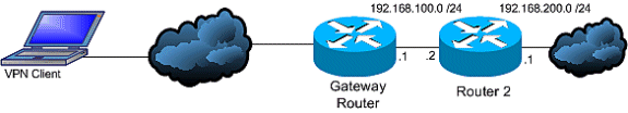
In a Remote Access configuration, routing changes are not always necessary. Yet, if other routers exist behind the VPN gateway router or Security Appliance, those routers need to learn the path to the VPN clients somehow. In this example, suppose that the VPN clients are given addresses in the range of 10.0.0.0 /24 when they connect.
If no routing protocol is in use between the gateway and the other router(s), static routes can be used on routers such as Router 2:
ip route 10.0.0.0 255.255.255.0 192.168.100.1
If a routing protocol such as EIGRP or OSPF is in use between the gateway and other routers, it is recommended that Reverse Route Injection be used as described. RRI automatically adds routes for the VPN client to the routing table of the gateway. These routes can then be distributed to the other routers in the network.
-
Cisco IOS Router:
crypto dynamic-map dynMAP 10
 set transform-set mySET
 reverse-route

crypto map myMAP 60000 ipsec-isakmp dynamic dynMAP
-
Cisco PIX or ASA Security Appliance:
crypto dynamic-map dynMAP 10 set transform-set mySET
crypto dynamic-map dynMAP 10 set reverse-route

crypto map myMAP 60000 ipsec-isakmp dynamic dynMAP
-

Note: The routing issue occurs if the pool of IP addresses assigned for the VPN clients are overlaps with internal networks of the head-end device. For further information, refer to the Overlapping Private Networks section .
Verify that Transform-Set is Correct
Make sure that the IPsec encryption and hash algorithms to be used by the transform set on the both ends are the same. Refer to the Command reference section of the Cisco Security Appliance configuration guide for more information.
Note: For the ISAKMP policy and IPsec Transform-set that is used on the PIX/ASA, the Cisco VPN client cannot use a policy with a combination of DES and SHA. If you use DES, you need to use MD5 for the hash algorithm, or you can use the other combinations, 3DES with SHA and 3DES with MD5.
Verify Crypto Map Sequence Numbers and Name and also that the Crypto map is applied in the right interface in which the IPsec tunnel start/end
If static and dynamic peers are configured on the same crypto map, the order of the crypto map entries is very important. The sequence number of the dynamic crypto map entry must be higher than all of the other static crypto map entries. If the static entries are numbered higher than the dynamic entry, connections with those peers fail and the debugs as shown appears.
IKEv1]: Group = x.x.x.x, IP = x.x.x.x, QM FSM error (P2 struct &0x49ba5a0, mess id 0xcd600011)!
[IKEv1]: Group = x.x.x.x, IP = x.x.x.x, Removing peer from correlator table failed, no match!
Note: Only one Dynamic Crypto-map is allowed for each interface in the Security Appliance.
Here is an example of a properly numbered crypto map that contains a static entry and a dynamic entry. Note that the dynamic entry has the highest sequence number and room has been left to add additional static entries:
crypto dynamic-map cisco 20 set transform-set myset
crypto map mymap 10 match address 100
crypto map mymap 10 set peer 172.16.77.10
crypto map mymap 10 set transform-set myset
crypto map mymap interface outside
crypto map mymap 60000 ipsec-isakmp dynamic cisco
Note: Crypto map names are case-sensitive.
Note: This error message can also be seen when the dynamic crypto man sequence is not correct which causes the peer to hit the wrong crypto map, and also by a mismatched crypto access list that defines the interesting traffic: %ASA-3-713042: IKE Initiator unable to find policy:
In the scenarios where multiple VPN tunnels to be terminated in the same interface, we need to create crypto map with same name (only one crypto map is allowed per interface) but with a different sequence number. This holds true for the router, PIX, and ASA.
Refer to Configuring IPsec Between Hub and Remote PIXes with VPN Client and Extended Authentication for more information in order to learn more about the hub PIX configuration for the same crypto map with the different sequence numbers on the same interface. Similarly, refer to PIX/ASA 7.X: Add a New Tunnel or Remote Access to an Existing L2L VPN for more information in order to learn more about the crypto map configuration for both L2L and Remote Access VPN scenarios.
Verify the Peer IP Address is Correct
For a PIX/ASA Security Appliance 7.x LAN-to-LAN (L2L) IPsec VPN configuration, you must specify the <name> of the tunnel group as theRemote peer IP Address(remote tunnel end) in the tunnel-group <name> type ipsec-l2l command for the creation and management of the database of connection-specific records for IPsec. The peer IP address must match in tunnel group name and the Crypto map set address commands. While you configure the VPN with ASDM, it generated the tunnel group name automatically with right peer IP address. If the peer IP Address is not configured properly, the logs can contain this message, which can be resolved by proper configuration of the Peer IP Address.
[IKEv1]: Group = DefaultL2LGroup, IP = x.x.x.x,
ERROR, had problems decrypting packet, probably due to mismatched pre-shared key. Aborting
In PIX 6.x LAN-to-LAN (L2L) IPsec VPN configuration, the Peer IP address (remote tunnel end) must match isakmp key address and the set peer command in crypto map for a successful IPsec VPN connection.
When the peer IP address has not been configured properly on the ASA crypto configuration, the ASA is not able to establish the VPN tunnel and hangs in the MM_WAIT_MSG4 stage only. In order to resolve this issue, correct the peer IP address in the configuration.
Here is the output of the show crypto isakmp sa command when the VPN tunnel hangs at in the MM_WAIT_MSG4 state.
hostname#show crypto isakmp sa

1   IKE Peer: XX.XX.XX.XX
    Type    : L2L             Role    : initiator
    Rekey   : no              State   : MM_WAIT_MSG4
Verify the Tunnel Group and Group Names
%PIX|ASA-3-713206: Tunnel Rejected: Conflicting protocols specified by
tunnel-group and group-policy
The message appears when a tunnel is dropped because the allowed tunnel specified in the group policy is different than the allowed tunnel in the tunnel-group configuration.
group-policy hf_group_policy attributes
  vpn-tunnel-protocol l2tp-ipsec

username hfremote attributes
  vpn-tunnel-protocol l2tp-ipsec

Both lines should read:
  vpn-tunnel-protocol ipsec l2tp-ipsec
Enable IPSec In Default Group policy to the already Existing Protocols In Default Group Policy .
group-policy DfltGrpPolicy attributes
   vpn-tunnel-protocol L2TP-IPSec IPSec webvpn
Disable XAUTH for L2L Peers
If a LAN-to-LAN tunnel and a Remote Access VPN tunnel are configured on the same crypto map, the LAN-to-LAN peer is prompted for XAUTH information, and the LAN-to-LAN tunnel fails with « CONF_XAUTH » in the output of the show crypto isakmp sa command.
Here is an example of the SA output:
Router#show crypto isakmp sa
IPv4 Crypto ISAKMP SA
dst             src             state          conn-id  slot  status
X.X.X.X         Y.Y.Y.Y         CONF_XAUTH       10223    0   ACTIVE
X.X.X.X         Z.Z.Z.Z         CONF_XAUTH       10197    0   ACTIVE
Note: This issue only applies to Cisco IOS and PIX 6.x. whereas PIX/ASA 7.x is not affected by this issue since it uses tunnel-groups.
Use the no-xauth keyword when you enter the isakmp key, so the device does not prompt the peer for XAUTH information (username and password). This keyword disables XAUTH for static IPsec peers. Enter a command similar to this on the device that has both L2L and RA VPN configured on the same crypto map:
router(config)#crypto isakmp key cisco123 address
   172.22.1.164 no-xauth
In the scenario where the PIX/ASA 7.x acts as the Easy VPN Server, the easy VPN client is unable to connect to head end because of the Xauth issue. Disable the user authentication in the PIX/ASA in order to resolve the issue as shown:
ASA(config)#tunnel-group example-group type ipsec-ra
ASA(config)#tunnel-group example-group ipsec-attributes
ASA(config-tunnel-ipsec)#isakmp ikev1-user-authentication none
See the Miscellaneous section of this document in order to know more about the isakmp ikev1-user-authentication command.
VPN Pool Getting Exhausted
When the range of IP addresses assigned to the VPN pool are not sufficient, you can extend the availability of IP addresses in two ways:
-
Remove the existing range, and define the new range. Here is an example:
CiscoASA(config)#no ip local pool testvpnpool 10.76.41.1-10.76.41.254
CiscoASA(config)#ip local pool testvpnpool 10.76.41.1-10.76.42.254
-
When discontiguous subnets are to be added to the VPN pool, you can define two separate VPN pools and then specify them in order under the «tunnel-group attributes». Here is an example:
CiscoASA(config)#ip local pool testvpnpoolAB 10.76.41.1-10.76.42.254
CiscoASA(config)#ip local pool testvpnpoolCD 10.76.45.1-10.76.45.254
CiscoASA(config)#tunnel-group test type remote-access
CiscoASA(config)#tunnel-group test general-attributes
CiscoASA(config-tunnel-general)#address-pool (inside) testvpnpoolAB testvpnpoolCD
CiscoASA(config-tunnel-general)#exit
The order in which you specify the pools is very important because the ASA allocates addresses from these pools in the order in which the pools appear in this command.
Note: The address-pools settings in the group-policy address-pools command always override the local pool settings in the tunnel-group address-pool command.
Issues with Latency for VPN Client Traffic
When there are latency issues over a VPN connection, verify the following in order to resolve this:
-
Verify if the MSS of the packet can be reduced further.
-
If IPsec/tcp is used instead of IPsec/udp, then configure preserve-vpn-flow.
-
Re-load the Cisco ASA.
VPN Clients are Unable to Connect with ASA/PIX
Problem
Cisco VPN clients are unable to authenticate when the X-auth is used with the Radius server.
Solution
The problem can be that the xauth times out. Increase the timeout value for AAA server in order to resolve this issue.
For example:
Hostname(config)#aaa-server test protocol radius
hostname(config-aaa-server-group)#aaa-server test host 10.2.3.4
hostname(config-aaa-server-host)#timeout 10
Problem
Cisco VPN clients are unable to authenticate when the X-auth is used with the Radius server.
Solution
Initially, make sure that the authentication works properly. To narrow down the problem, first verify the authentication with local database on ASA.
tunnel-group tggroup general-attributes
              authentication-server-group none
              authentication-server-group LOCAL
        exit
If this works fine, then the problem should be related to Radius server configuration.
Verify the connectivity of the Radius server from the ASA. If the ping works without any problem, then check the Radius-related configuration on ASA and database configuration on the Radius server.
You could use the debug radius command to troubleshoot radius related issues. For sample debug radius output, refer to this Sample Output .
Note: Before you use the debug command on the ASA, refer to this documentation: Warning message .
VPN Client Drops Connection Frequently on First Attempt or «Security VPN Connection terminated by peer. Reason 433.» or «Secure VPN Connection terminated by Peer Reason 433:(Reason Not Specified by Peer)»
Problem
Cisco VPN client users might receive this error when they attempt the connection with the head end VPN device.
«VPN client drops connection frequently on first attempt» or «Security VPN Connection terminated by peer. Reason 433.» or «Secure VPN Connection terminated by Peer Reason 433:(Reason Not Specified by Peer)» or «Attempted to assign network or broadcast IP address, removing (x.x.x.x) from pool«
Solution 1
The problem might be with the IP pool assignment either through ASA/PIX, Radius server, DHCP server or through Radius server acting as DHCP server. Use the debug crypto command in order to verify that the netmask and IP addresses are correct. Also, verify that the pool does not include the network address and the broadcast address. Radius servers must be able to assign the proper IP addresses to the clients.
Solution 2
This issue also occurs due to the failure of extended authentication. You must check the AAA server to troubleshoot this error. Checking the server authentication password on Server and client and reloading the AAA server might resolve this issue.
Solution 3
Another workaround for this issue is to disable the threat detection feature. At times when there are multiple re-transmissions for different incomplete Security Associations (SAs), the ASA with the threat-detection feature enabled thinks that a scanning attack is occuring and the VPN ports are marked as the main offender. Try to disable the threat-detection feature as this can cause a lot of overhead on the processing of ASA. Use these commands in order to disable the threat detection:
no threat-detection basic-threat
no threat-detection scanning-threat shun
no threat-detection statistics
no threat-detection rate
For more information about this feature, refer to Threat Detection.
Note: This can be used as a workaround to verify if this fixes the actual problem. Make sure that disabling the threat detection on the Cisco ASA actually compromises several security features such as mitigating the Scanning Attempts, DoS with Invalid SPI, packets that fail Application Inspection and Incomplete Sessions.
Solution 4
This issue also occurs when a transform set is not properly configured. A proper configuration of the transform set resolves the issue.
Remote Access and EZVPN Users Connect to VPN but Cannot Access External Resources
Problem
Remote access users have no Internet connectivity once they connect to the VPN.
Remote access users cannot access resources located behind other VPNs on the same device.
Remote access users can access only the local network.
Solutions
Try these solutions in order to resolve this issue:
-
Unable to Access the Servers in DMZ
-
VPN Clients Unable to Resolve DNS
-
Split-Tunnel—Unable to access Internet or excluded networks
-
Hairpinning
-
Local LAN Access
-
Overlapping Private Networks
Unable to Access the Servers in DMZ
Once the VPN client is established the IPsec tunnel with the VPN head-end device (PIX/ASA/IOS Router), the VPN client users are able to access the INSIDE network (10.10.10.0/24) resources, but they are unable to access the DMZ network (10.1.1.0/24).
Diagram
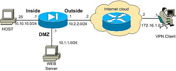
Check that the Split Tunnel, NO NAT configuration is added in the head-end device to access the resources in the DMZ network.
Example
| ASA/PIX |
|---|
ciscoasa#show running-config !--- Split tunnel for the inside network access access-list vpnusers_spitTunnelAcl permit ip 10.10.10.0 255.255.0.0 any !--- Split tunnel for the DMZ network access access-list vpnusers_spitTunnelAcl permit ip 10.1.1.0 255.255.0.0 any !--- Create a pool of addresses from which IP addresses are assigned !--- dynamically to the remote VPN Clients. ip local pool vpnclient 192.168.1.1-192.168.1.5 !--- This access list is used for a nat zero command that prevents !--- traffic which matches the access list from undergoing NAT. !--- No Nat for the DMZ network. access-list nonat-dmz permit ip 10.1.1.0 255.255.255.0 192.168.1.0 255.255.255.0 !--- No Nat for the Inside network. access-list nonat-in permit ip 10.10.10.0 255.255.255.0 192.168.1.0 255.255.255.0 !--- NAT 0 prevents NAT for networks specified in the ACL nonat . nat (DMZ) 0 access-list nonat-dmz nat (inside) 0 access-list nonat-in |
ASA version 8.3 configuration:
This configuration shows how to configure the NAT exemption for the DMZ network in order to enable the VPN users to access the DMZ network:
object network obj-dmz
subnet 10.1.1.0 255.255.255.0
object network obj-vpnpool
subnet 192.168.1.0 255.255.255.0
nat (inside,dmz) 1 source static obj-dmz obj-dmz destination static obj-vpnpool obj-vpnpool
After you add a new entry for the NAT configuration, clear the NAT translation.
Clear xlate
Clear local
Verify:
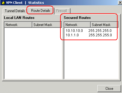
If the tunnel has been established, go to the Cisco VPN Client and choose Status > Route Details to check that the secured routes are shown for both the DMZ and INSIDE networks.
Refer to PIX/ASA 7.x: Mail Server Access on the DMZ Configuration Example for more information on how to set up the PIX Firewall for access to a mail server located on the Demilitarized Zone (DMZ) network.
Refer to PIX/ASA 7.x: Add a New Tunnel or Remote Access to an Existing L2L VPN in order to provide the steps required to add a new VPN tunnel or a remote access VPN to a L2L VPN configuration that already exists.
Refer to PIX/ASA 7.x: Allow Split Tunneling for VPN Clients on the ASA Configuration Example in order to provide step-by-step instructions on how to allow VPN Clients access to the Internet while they are tunneled into a Cisco Adaptive Security Appliance (ASA) 5500 Series Security Appliance.
Refer to PIX/ASA 7.x and Cisco VPN Client 4.x with Windows 2003 IAS RADIUS (Against Active Directory) Authentication Configuration Example for more information on how to set up the remote access VPN connection between a Cisco VPN Client (4.x for Windows) and the PIX 500 Series Security Appliance 7.x.
VPN Clients Unable to Resolve DNS
After the tunnel has been established, if the VPN Clients are unable to resolve the DNS, the problem can be the DNS Server configuration in the head-end device (ASA/PIX). Also check the connectivity between the VPN Clients and the DNS Server. The DNS Server configuration must be configured under the group policy and applied under the the group policy in the tunnel-group general attributes; for example:
!--- Create the group policy named vpn3000 and !--- specify the DNS server IP address(172.16.1.1) !--- and the domain name(cisco.com) in the group policy.

group-policy vpn3000 internal
group-policy vpn3000 attributes
 dns-server value 172.16.1.1
 default-domain value cisco.com


!--- Associate the group policy(vpn3000) to the tunnel group !--- using the default-group-policy.

tunnel-group vpn3000 general-attributes
 default-group-policy vpn3000
VPN clients unable to connect internal servers by name
The VPN client is unable to ping the hosts or servers of the remote or head end internal network by name. You need to enable the split-dns configure on ASA in order to resolve this issue.
Split-Tunnel—Unable to access Internet or excluded networks
Split tunneling lets remote-access IPsec clients conditionally direct packets over the IPsec tunnel in encrypted form or direct packets to a network interface in cleartext form, decrypted, where they are then routed to a final destination. Split-tunneling is disabled by default, which is tunnelall traffic.
split-tunnel-policy {tunnelall | tunnelspecified | excludespecified}
Note: The option excludespecified is supported only for Cisco VPN clients, not EZVPN clients.
ciscoasa(config-group-policy)#split-tunnel-policy excludespecified
Refer to these documents for detailed configuration examples of split-tunneling:
-
PIX/ASA 7.x: Allow Split Tunneling for VPN Clients on the ASA Configuration Example
-
Router Allows VPN Clients to Connect IPsec and Internet Using Split Tunneling Configuration Example
-
Split Tunneling for VPN Clients on the VPN 3000 Concentrator Configuration Example
Hairpinning
This feature is useful for VPN traffic that enters an interface but is then routed out of that same interface. For example, if you have a hub and spoke VPN network, where the security appliance is the hub and remote VPN networks are spokes, in order for one spoke to communicate with another spoke, traffic must go into the security appliance and then out again to the other spoke.
Use the same-security-traffic configuration to allow traffic to enter and exit the same interface.
securityappliance(config)#same-security-traffic permit intra-interface
Local LAN Access
Remote access users connect to the VPN and are able to connect to local network only.
For a more detailed configuration example, refer to PIX/ASA 7.x: Allow local LAN access for VPN clients.
Overlapping Private Networks
Problem
If you are unable to access the internal network after the tunnel establishment, check the IP address assigned to the VPN client that overlaps with the internal network behind the head-end device.
Solution
Always make sure that the IP addresses in the pool to be assigned for the VPN clients, the internal network of the head-end device and the VPN Client internal network must be in different networks. You can assign the same major network with different subnets, but sometimes the routing issues occur.
For further examples, see the Diagram and Example of the Unable to Access the Servers in DMZ section.
Unable to Connect More Than Three VPN Client Users
Problem
Only three VPN clients can connect to ASA/PIX; connection for the fourth client fails. Upon failure, this error message is displayed:
Secure VPN Connection terminated locally by the client.
	 Reason 413: User Authentication failed.
tunnel rejected; the maximum tunnel count has been reached
Solutions
In most cases, this issue is related to a simultaneous login setting within group policy and the maximum session-limit.
Try these solutions in order to resolve this issue:
-
Configure Simultaneous Logins
-
Configure the ASA/PIX with CLI
-
Configure Concentrator Configure Concentrator
For more information, refer to the Configuring Group Policies section of Selected ASDM VPN Configuration Procedures for the Cisco ASA 5500 Series, Version 5.2.
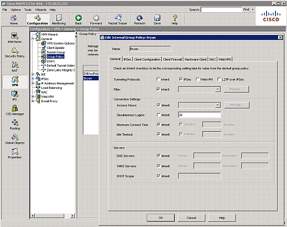
Configure Simultaneous Logins
If the Inherit check box in ASDM is checked, only the default number of simultaneous logins is allowed for the user. The default value for simultaneous logins is three.
In order to resolve this issue, increase the value for simultaneous logins.
-
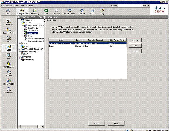
Launch ASDM and then navigate to Configuration > VPN > Group Policy.
-
Choose the appropriate Group and click the Edit button.
-
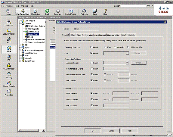
Once in the General tab, undo the Inherit check box for Simultaneous Logins under Connection Settings. Choose an appropriate value in the field.
Note: The minimum value for this field is 0, which disables login and prevents user access.
Note: When you log in using the same user account from a different PC, the current session (the connection established from another PC using the same user account) is terminated, and the new session is established. This is the default behaviour and is independent to VPN simultaneous logins.
Configure the ASA/PIX with CLI
Complete these steps in order to configure the desired number of simultaneous logins. In this example, 20 was chosen as the desired value.
ciscoasa(config)#group-policy Bryan attributes
ciscoasa(config-group-policy)#vpn-simultaneous-logins 20
In order to learn more about this command, refer to Cisco Security Appliance Command Reference, Version 7.2.
Use the vpn-sessiondb max-session-limit command in global configuration mode in order to limit VPN sessions to a lower value than the security appliance allows. Use the no version of this command in order to remove the session limit. Use the command again in order to overwrite the current setting.
vpn-sessiondb max-session-limit {session-limit}
This example shows how to set a maximum VPN session limit of 450:
hostname#vpn-sessiondb max-session-limit 450
Configure Concentrator
Error Message
20932 10/26/2007 14:37:45.430 SEV=3 AUTH/5 RPT=1863 10.19.187.229
Authentication rejected: Reason = Simultaneous logins exceeded for user
handle = 623, server = (none), user = 10.19.187.229, domain = <not
specified>
Solution
Complete these steps in order to configure the desired number of simultaneous logins. You can also try to set the Simultaneous Logins to 5 for this SA:
Choose Configuration > User Management > Groups > Modify 10.19.187.229 > General > Simultaneous Logins, and change the number of logins to 5.
Unable to Initiate the Session or an Application and Slow Transfer after the Tunnel Establishment
Problem
After the IPsec tunnel establishment, the application or the session does not initiate across the tunnel.
Solutions
Use the ping command to check the network or find whether the application server is reachable from your network. It can be a problem with the maximum segment size (MSS) for transient packets that traverse a router or PIX/ASA device, specifically TCP segments with the SYN bit set.
Cisco IOS Router—Change the MSS Value in the Outside Interface (Tunnel End Interface) of the Router
Run these commands in order to change the MSS value in the outside interface (tunnel end interface) of the router:
Router>enable
Router#configure terminal
Router(config)#interface ethernet0/1
Router(config-if)#ip tcp adjust-mss 1300
Router(config-if)#end
These messages show the debug output for TCP MSS:
Router#debug ip tcp transactions

Sep 5 18:42:46.247: TCP0: state was LISTEN -> SYNRCVD [23 -> 10.0.1.1(38437)]
Sep 5 18:42:46.247: TCP: tcb 32290C0 connection to 10.0.1.1:38437, peer MSS 1300, MSS is
1300
Sep 5 18:42:46.247: TCP: sending SYN, seq 580539401, ack 6015751
Sep 5 18:42:46.247: TCP0: Connection to 10.0.1.1:38437, advertising MSS 1300
Sep 5 18:42:46.251: TCP0: state was SYNRCVD -> ESTAB [23 -> 10.0.1.1(38437)]
The MSS gets adjusted to 1300 on the router as configured.
For more information, refer to PIX/ASA 7.x and IOS: VPN Fragmentation.
PIX/ASA 7.X—Refer to PIX/ASA Documentation
There is an inability to access the Internet properly or slow transfer through the tunnel because it gives the MTU size error message and MSS issues. Refer to these documents in order to resolve the issue:
-
PIX/ASA 7.x and IOS: VPN Fragmentation
-
PIX/ASA 7.0 Issue: MSS Exceeded — HTTP Clients Cannot Browse to Some Web Sites
Unable to Initiate VPN Tunnel from ASA/PIX
Problem
You are unable to initiate the VPN tunnel from ASA/PIX interface, and after the tunnel establishment, the remote end/VPN Client is unable to ping the inside interface of ASA/PIX on the VPN tunnel. For example, the pn client can be unable to initiate a SSH or HTTP connection to ASA’s inside interface over VPN tunnel.
Solution
The inside interface of the PIX cannot be pinged from the other end of the tunnel unless the management-access command is configured in the global configuration mode.
PIX-02(config)#management-access inside

PIX-02(config)#show management-access
management-access inside
Note: This command also helps in initiating a ssh or http connection to inside interface of ASA through a VPN tunnel.
Note: This information holds true for DMZ interface as well. For example, if you want to ping the DMZ interface of PIX/ASA or want to initiate a tunnel from DMZ interface, then the management-access DMZ command is required.
PIX-02(config)#management-access DMZ
Note: If the VPN client is unable to connect, then make sure ESP and UDP ports are open, however if those ports are not open then try to connect on TCP 10000 with the selection of this port under the VPN client connection entry. Right click modify > transport tab > IPsec over TCP. Refer to PIX/ASA 7.x to Support IPsec over TCP on any Port Configuration Example for more information on IPsec over TCP.
Unable to Pass Traffic Across VPN Tunnel
Problem
You are unable to pass traffic across a VPN tunnel.
Solution
This issue occurs due to the problem described in Cisco bug ID CSCtb53186 (registered customers only) . In order to resolve this issue, reload the ASA. Refer to the bug for more information.
This issue might also occur when the ESP packets are blocked. In order to resolve this issue, reconfiguring the VPN tunnel.
This issue might occur when data is not encrypted, but only decrypted over the VPN tunnel as shown in this output:
ASA# sh crypto ipsec sa peer x.x.x.x
peer address: y.y.y.y
    Crypto map tag: IPSec_map, seq num: 37, local addr: x.x.x.x
      access-list test permit ip host xx.xx.xx.xx host yy.yy.yy.yy
      local ident (addr/mask/prot/port): (xx.xx.xx.xx/255.255.255.255/0/0)
      remote ident (addr/mask/prot/port): (yy.yy.yy.yy/255.255.255.255/0/0)
      current_peer: y.y.y.y

      #pkts encaps: 0, #pkts encrypt: 0, #pkts digest: 0
      #pkts decaps: 393, #pkts decrypt: 393, #pkts verify: 393
      #pkts compressed: 0, #pkts decompressed: 0
      #pkts not compressed: 0, #pkts comp failed: 0, #pkts decomp failed: 0
      #pre-frag successes: 0, #pre-frag failures: 0, #fragments created: 0
      #PMTUs sent: 0, #PMTUs rcvd: 0, #decapsulated frgs needing reassembly: 0
      #send errors: 0, #recv errors: 0
In order to resolve this issue, check the following:
-
If the crypto access-lists match with the remote site, and that NAT 0 access-lists are correct.
-
If routing is correct and traffic does hit outside interface passing through inside. The sample output shows that decryption is done, but encryption does not occur.
-
If the sysopt permit connection-vpn command has been configured on the ASA. If not configured, configure this command because it allows the ASA to exempt the encrypted/VPN traffic from interface ACL checking.
Configuring Backup peer for vpn tunnel on same crypto map
Problem
You want to use multiple backup peers for a single vpn tunnel.
Solution
Configuring multiple peers is equivalent to providing a fallback list. For each tunnel, the security appliance attempts to negotiate with the first peer in the list.
If that peer does not respond, the security appliance works its way down the list until either a peer responds or there are no more peers in the list.
The ASA should have a crypto map already configured as the primary peer. The secondary peer could be added after the primary one.
This example configuration shows the primary peer as X.X.X.X and backup peer as Y.Y.Y.Y:
ASA(config)#crypto map mymap 10 set peer X.X.X.X Y.Y.Y.Y
For more information, refer to the Crypto map set peer section in the Cisco Security Appliance Command Reference, Version 8.0.
Disable/Restart VPN Tunnel
Problem
In order to temporarily disable the VPN tunnel and restart the service, complete the procedure described in this section.
Solution
Use the crypto map interface command in global configuration mode to remove a previously defined crypto map set to an interface. Use the no form of this command in order to remove the crypto map set from the interface.
hostname(config)#no crypto map map-name interface interface-name
This command removes a crypto map set to any active security appliance interface and make the IPsec VPN tunnel inactive in that interface.
To restart the IPsec tunnel on an interface, you must assign a crypto map set to an interface before that interface can provide IPsec services.
hostname(config)#crypto map map-name interface interface-name
Some Tunnels not Encrypted
Problem
When a huge number of tunnels are configured on the VPN gateway, some tunnels do not pass traffic. The ASA does not receive encrypted packets for those tunnels.
Solution
This issue occurs because the ASA fails to pass the encrypted packets through the tunnels. Duplicate encryption rules are created in the ASP table. This is a known issue and bug ID CSCtb53186 (registered customers only) has been filed to address this problem. In order to resolve this issue, either reload the ASA or upgrade the software to a version in which this bug is fixed.
Error:- %ASA-5-713904: Group = DefaultRAGroup, IP = x.x.x.x, Client is using an unsupported Transaction Mode v2 version.Tunnel terminated.
Problem
The %ASA-5-713904: Group = DefaultRAGroup, IP = 99.246.144.186, Client is using an unsupported Transaction Mode v2 version.Tunnel terminated error message appears.
Solution
The reason for the Transaction Mode v2 error message is that ASA supports only IKE Mode Config V6 and not the old V2 mode version. Use the IKE Mode Config V6 version in order to resolve this error.
Error:- %ASA-6-722036: Group client-group User xxxx IP x.x.x.x Transmitting large packet 1220 (threshold 1206)
Problem
The %ASA-6-722036: Group < client-group > User < xxxx > IP < x.x.x.x> Transmitting large packet 1220 (threshold 1206) error message appears in the logs of ASA. What does this log means and how this can be resolved?
Solution
This log message states that a large packet was sent to the client. The source of the packet is not aware of the MTU of the client. This can also be due to compression of non-compressible data. The workaround is to turn off the SVC compression with the svc compression none command, which resolves the issue.
Error: The authentication-server-group none command has been deprecated
Problem
If you transfer the VPN configuration from the PIX/ASA that runs Version 7.0.x to the another security appliance that runs 7.2.x, you receive this error message:
ERROR: The authentication-server-group none command has been deprecated.
The "isakmp ikev1-user-authentication none" command in the ipsec-attributes should be used
instead.
Solution
The command authentication-server-group is no longer supported in 7.2(1) and later. This command was deprecated and moved to tunnel-group general-attributes configuration mode.
Refer to the isakmp ikev1-user-authentication section of the command reference for more information about this command.
Error Message when QoS is Enabled in one End of the VPN Tunnel
Problem
If you enabled QoS in one end of the VPN Tunnel, you might receive this error message:
IPSEC: Received an ESP packet (SPI= 0xDB6E5A60, sequence number= 0x7F9F) from
10.18.7.11 (user= ghufhi) to 172.16.29.23 that failed anti-replay checking
Solution
This message is normally caused when one end of the tunnel is doing QoS. This happens when a packet is detected as being out of order. You can disable QoS to stop this but it can be ignored as long as traffic is able to traverse the tunnel.
WARNING: crypto map entry will be incomplete
Problem
When you run the crypto map mymap 20 ipsec-isakmp command, you might receive this error:
WARNING: crypto map entry will be incomplete
For example:
ciscoasa(config)#crypto map mymap 20 ipsec-isakmp
WARNING: crypto map entry will be incomplete
Solution
This is a usual warning when you define a new crypto map, a reminder that parameters such as access-list (match address), transform set and peer address must be configured before it can work. It is also normal that the first line you type in order to define the crypto map does not show in the configuration.
Error:- %ASA-4-400024: IDS:2151 Large ICMP packet from to on interface outside
Problem
Unable to pass large ping packet across the vpn tunnel. When we try to pass large ping packets we get the error %ASA-4-400024: IDS:2151 Large ICMP packet from to on interface outside
Solution
Disable the signatures 2150 and 2151 in order to resolve this issue.Once the signatures are disabled ping works fine.
Use these commands in order to disable the signatures:
ASA(config)#ip audit signature 2151 disable
ASA(config)#ip audit signature 2150 disable
Error:- %PIX|ASA-4-402119: IPSEC: Received a protocol packet (SPI=spi, sequence number= seq_num) from remote_IP (username) to local_IP that failed anti-replay checking.
Problem
I received this error in the log messages of the ASA:
Error:- %PIX|ASA-4-402119: IPSEC: Received a protocol packet (SPI=spi, sequence number= seq_num) from remote_IP (username) to local_IP that failed anti-replay checking.
Solution
In order to resolve this error, use the crypto ipsec security-association replay window-size command in order to vary the window size.
hostname(config)#crypto ipsec security-association replay window-size 1024
Note: Cisco recommends that you use the full 1024 window size to eliminate any anti-replay problems.
Error Message — %PIX|ASA-4-407001: Deny traffic for local-host interface_name:inside_address, license limit of number exceeded
Problem
Few hosts are unable to connect to the Internet, and this error message appears in the syslog:
Error Message — %PIX|ASA-4-407001: Deny traffic for local-host interface_name:inside_address, license limit of number exceeded
Solution
This error message is received when the number of users exceeds the user limit of the license used. This error can be resolved by upgrading the license to a higher number of users. The user license can include 50, 100, or unlimited users as required.
Error Message — %VPN_HW-4-PACKET_ERROR:
Problem
The Error Message — %VPN_HW-4-PACKET_ERROR: error message indicates that ESP packet with HMAC received by the router are mismatched. This error might be caused by these issues:
-
Defective VPN H/W module
-
Corrupt ESP packet
Solution
In order to resolve this error message:
-
Ignore the error messages unless there is traffic disruption.
-
If there is traffic disruption, replace the module.
Error message: Command rejected: delete crypto connection between VLAN XXXX and XXXX, first.
Problem
This error message appears when you attempt to add an allowed VLAN on the trunk port on a switch: Command rejected: delete crypto connection between VLAN XXXX and VLAN XXXX, first..
The WAN edge trunk cannot be modified to allow additional VLANs. That is, you are unable to add VLANs in the IPSEC VPN SPA trunk.
This command is rejected because allowing it will result in a crypto connected interface VLAN that belongs to the interface’s allowed VLAN list, which poses a potential IPSec security breach. Note that this behavior applies to all trunk ports.
Solution
Instead of the no switchport trunk allowed vlan (vlanlist) command, use the switchport trunk allowed vlan none command or the «switchport trunk allowed vlan remove (vlanlist)» command.
Error Message — % FW-3-RESPONDER_WND_SCALE_INI_NO_SCALE: Dropping packet — Invalid Window Scale option for session x.x.x.x:27331 to x.x.x.x:23 [Initiator(flag 0,factor 0) Responder (flag 1, factor 2)]
Problem
This error occurs when you try to telnet from a device on the far end of a VPN tunnel or when you try to telnet from the router itself:
Error Message — % FW-3-RESPONDER_WND_SCALE_INI_NO_SCALE: Dropping packet — Invalid Window Scale option for session x.x.x.x:27331 to x.x.x.x:23 [Initiator(flag 0,factor 0) Responder (flag 1, factor 2)]
Solution
The user license can include 50, 100, or unlimited users as required. Window scaling was added to allow for rapid transmission of data on long fat networks (LFN). These are typically connections with very high bandwidth, but also high latency. Networks with satellite connections are one example of an LFN, since satellite links always have high propagation delays but typically have high bandwidth. To enable window scaling to support LFNs, the TCP window size must be more than 65,535. This error message can be resolved by increasing the TCP window size to be more than 65,535.
%ASA-5-305013: Asymmetric NAT rules matched for forward and reverse . Please update this issue flows
Problem
This error message appears once the VPN tunnel comes up:
%ASA-5-305013: Asymmetric NAT rules matched for forward and reverse . Please update this issue flows
Solution
In order to resolve this issue when not on the same interface as the host using NAT, use the mapped address instead of the actual address to connect to the host. In addition, enable the inspect command if the application embeds the IP address.
%PIX|ASA-5-713068: Received non-routine Notify message: notify_type
Problem
This error message appears if the VPN tunnel fails to come up:
%PIX|ASA-5-713068: Received non-routine Notify message: notify_type
Solution
This message occurs due to misconfiguration (that is, when the policies or ACLs are not configured to be the same on peers). Once the policies and ACLs are matched the tunnel comes up without any problem.
%ASA-5-720012: (VPN-Secondary) Failed to update IPSec failover runtime data on the standby unit (or) %ASA-6-720012: (VPN-unit) Failed to update IPsec failover runtime data on the standby unit
Problem
One of these error messages appear when you try to upgrade the Cisco Adaptive Security Appliance (ASA):
%ASA-5-720012: (VPN-Secondary) Failed to update IPSec failover runtime data on the standby unit.
%ASA-6-720012: (VPN-unit) Failed to update IPsec failover runtime data on the standby unit.
Solution
These error messages are informative errors. The messages do not impact functionality of the ASA or the VPN.
These messages appear when the VPN failover subsystem cannot update IPsec-related runtime data because the corresponding IPsec tunnel has been deleted on the standby unit. In order to resolve these, issue the wr standby command on the active unit.
Two bugs have been filed to address this behavior and upgrade to a software version of ASA where these bugs are fixed. Refer to Cisco bug IDs CSCtj58420 (registered customers only) and CSCtn56517 (registered customers only) for more information.
Error:- %ASA-3-713063: IKE Peer address not configured for destination 0.0.0.0
Problem
The %ASA-3-713063: IKE Peer address not configured for destination 0.0.0.0 error message appears and the tunnel fails to come up.
Solution
This message appears when the IKE peer address is not configured for a L2L tunnel. This error can be resolved by changing the sequence number of crypto map, then removing and reapplying the crypto map.
Error: %ASA-3-752006: Tunnel Manager failed to dispatch a KEY_ACQUIRE message.
Problem
The %ASA-3-752006: Tunnel Manager failed to dispatch a KEY_ACQUIRE message.Probable mis-configuration of the crypto map or tunnel-group.» error message is logged on the Cisco ASA.
Solution
This error message can be caused by a misconfiguration of the crypto map or tunnel group. Ensure that both are configured properly. For more information about this error message, refer to Error 752006.
Here are some of the corrective actions:
-
Remove the crypto ACL (for example, associated to dynamic map).
-
Remove unused IKEv2 related configuration, if any.
-
Verify that the crypto ACL matched properly.
-
Remove duplicate access-list entries, if any.
Error: %ASA-4-402116: IPSEC: Received an ESP packet (SPI= 0x99554D4E, sequence number= 0x9E) from XX.XX.XX.XX (user= XX.XX.XX.XX) to YY.YY.YY.YY
In a LAN-to-LAN VPN tunnel setup, this error is received on one end ASA:
The decapsulated inner packet doesn’t match the negotiated policy in the SA.
The packet specifies its destination as 10.32.77.67, its source as 10.105.30.1, and its protocol as icmp.
The SA specifies its local proxy as 10.32.77.67/255.255.255.255/ip/0 and its remote_proxy as 10.105.42.192/255.255.255.224/ip/0.
Solution
You need to verify the interesting traffic access-lists defined on both ends of the VPN tunnel. Both should match as exact mirror images.
Failed to launch 64-bit VA installer to enable the virtual adapter due to error 0xffffffff
Problem
The Failed to launch 64-bit VA installer to enable the virtual adapter due to error 0xffffffff log message is received when AnyConnect fails to connect.
Solution
Complete these steps in order to resolve this issue:
-
Go to System > Internet Communication Management > Internet Communication settings and make sure that Turn Off Automatic Root Certificates Update is disabled.
-
If it is disabled, then disable the entire Administrative Template part of the GPO assigned to the affected machine and test again.
Refer to Turn off Automatic Root Certificates Update ![]() for more information.
for more information.
Error 5: No hostname exists for this connection entry. Unable to make VPN connection.
Problem
The Error 5: No hostname exists for this connection entry. Unable to make VPN connection error message is received during a new PC installation.
Solution
This issue is due to Cisco bug ID CSCso94244 (registered customers only) . Refer to this bug for more information.
Cisco VPN Client Does Not Work with Data Card on Windows 7
Problem
Cisco VPN Client does not work with data card on Windows 7.
Solution
Cisco VPN Client installed on Windows 7 does not work with 3G connections since data cards are not supported on VPN clients installed on a Windows 7 machine.
Warning Message: «VPN functionality may not work at all»
Problem
When trying to enable the isakmp on the outside interface of ASA, this warning message is received:
ASA(config)# crypto isakmp enable outside
WARNING, system is running low on memory.  Performance may start to degrade.
VPN functionality may not work at all.
At this point, access to ASA through ssh. HTTPS is stopped and other SSL clients are also affected.
Solution
This problem is due to memory requirements by different modules such as logger and crypto. Make sure you do not have the logging queue 0 command. It makes the queue size set to 8192 and the memory allocation shoots up.
In platforms such as ASA5505 and ASA5510, this memory allocation tends to memory-starve other modules (IKE and etc.). Cisco bug ID CSCtb58989 (registered customers only) has been logged to address a similar kind of behavior. In order to resolve this, configure the logging queue to a lesser value, such as 512.
IPSec Padding error
Problem
This error message is received:
%PIX|ASA-3-402130: CRYPTO: Received an ESP packet (SPI =
	 0xXXXXXXX, sequence number= 0xXXXX) from x.x.x.x (user= user) to y.y.y.y with
	 incorrect IPsec padding
Solution
The issue occurs because the IPSec VPN negotiates without a hashing algorithm. Packet hashing ensures integrity check for the ESP channel. Therefore, without hashing, malformed packets are accepted undetected by the Cisco ASA and it attempts to decrypt these packets. However, because these packets are malformed, the ASA finds flaws while decrypting the packet. This causes the padding error messages that are seen.
The recommendation is to include a hash algorithm in the transform set for the VPN and to ensure that the link between the peers has minimum packet malformation.
Dead Air delay time on remote site phones
Problem
Dead air delay time is experienced on remote site phones. How is this resolved?
Solution
Disable skinny and sip inspection in order to resolve this problem:
asa(config)# no inspect sip
asa(config)# no inspect skinny
VPN tunnel gets disconnected after every 18 hours
Problem
The VPN tunnel gets disconnected after every 18 hours even though the lifetime is set for 24 hours.
Solution
The lifetime is the maximum time the SA can be used for rekeying. The value you enter in the configuration as the lifetime is different from the rekey time of the SA. Therefore, it is necessary to negotiate a new SA (or SA pair in the case of IPsec) before the current one expires. The rekey time must always be smaller than the lifetime in order to allow for multiple attempts in case the first rekey attempt fails. The RFCs do not specify how to calculate the rekey time. This is left to the discretion of the implementers. Therefore, the time will vary depending on the platform used, which software version, etc.
Some implementations can use a random factor to calculate the rekey timer. For example, if the ASA initiates the tunnel, then it is normal that it will rekey at 64800 seconds = 75% of 86400. If the router initiates, then the ASA can wait longer to give the peer more time to initiate the rekey. Thus, it is normal that the VPN session gets disconnected every 18 hours to use another key for the VPN negotiation. This must not cause any VPN drop or problem.
Traffic flow is not maintained after the LAN to LAN tunnel is re-negotiated
Problem
Traffic flow is not maintained after the LAN to LAN tunnel is re-negotiated.
Solution
The ASA monitors every connection that passes through it and maintains an entry in its state table according to the application inspection feature. The encrypted traffic details that pass through the VPN are maintained in the form of a security association (SA) database. For LAN to LAN VPN connections, it maintains two different traffic flows. One is the encrypted traffic between the VPN gateways. The other is the traffic flow between the network resource behind the VPN gateway and the end-user behind the other end. When the VPN is terminated, the flow details for this particular SA are deleted. However, the state table entry maintained by the ASA for this TCP connection becomes stale because of no activity, which hampers the download. This means the ASA will still retain the TCP connection for that particular flow while the user application terminates. However, the TCP connections will become stray and eventually timeout after the TCP idle-timer expires.
This problem has been resolved by introducing a feature called Persistent IPSec Tunneled Flows. A new command, sysopt connection preserve-vpn-flows, has been integrated into the Cisco ASA in order to retain the state table information at the re-negotiation of the VPN tunnel. By default, this command is disabled. By enabling this, the Cisco ASA will maintain the TCP state table information when the L2L VPN recovers from the disruption and re-establishes the tunnel.
Error message states that Bandwidth reached for the Crypto functionality
Problem
This error message is received on the 2900 Series Router:
Error: Mar 20 10:51:29: %CERM-4-TX_BW_LIMIT: Maximum Tx Bandwidth limit of 85000 Kbps reached for Crypto functionality with securityk9 technology package license.
Solution
This is a known issue that occurs because of the strict guidelines issued by the United States government. According to this, the securityk9 license can only allow a payload encryption up to rates close to 90Mbps and limit the number of encrypted tunnels/TLS sessions to the device. For more information about the crypto export restrictions, refer to Cisco ISR G2 SEC and HSEC Licensing.
In case of Cisco devices, it is derived to be less than 85Mbps unidirectional traffic in or out of the ISR G2 router, with a bidirectional total of 170 Mbps. This requirement applies for the Cisco 1900, 2900, and 3900 ISR G2 platforms. This command helps you in viewing these limitations:
Router#show platform cerm-information
Crypto Export Restrictions Manager(CERM) Information:
CERM functionality: ENABLED
 ----------------------------------------------------------------
 Resource                       Maximum Limit           Available
 ----------------------------------------------------------------
 Tx Bandwidth(in kbps)          85000                   85000
 Rx Bandwidth(in kbps)          85000                   85000
 Number of tunnels                 225                       225
 Number of TLS sessions        1000                    1000
---Output truncated----
There is a bug filed to address this behavior. Refer to Cisco bug ID CSCtu24534 (registered customers only) for more information.
In order to avoid this problem, you need to purchase a HSECK9 license. An «hseck9» feature license provides enhanced payload encryption functionality with increased VPN tunnel counts and secure voice sessions. For more information about Cisco ISR Router licensing, refer to Software Activation.
Problem: Outbound encryption traffic in an IPsec tunnel may fail, even if inbound decryption traffic is working.
Solution
This issue has been observed on an IPsec connection after multiple rekeys, but the trigger condition is not clear. The presence of this issue can be established by checking the output of the show asp drop command and verifying that the Expired VPN context counter increases for each outbound packet sent. Refer to Cisco bug ID CSCtd36473 (registered customers only) for more information.
Miscellaneous
AG_INIT_EXCH Message Appears in the «show crypto isakmp sa» and «debug» Commands Output
If the tunnel does not get initiated, the AG_INIT_EXCH message appears in output of the show crypto isakmp sa command and in debug output as well. The reason can be due to mismatching isakmp policies or if port udp 500 gets blocked on the way.
Debug Message «Received an IPC message during invalid state» Appears
This message is an informational message and has nothing to do with the disconnection of the VPN tunnel.
Related Information
- PIX/ASA 7.0 Issue: MSS Exceeded — HTTP Clients Cannot Browse to Some Web Sites
- PIX/ASA 7.x and IOS: VPN Fragmentation
- Cisco ASA 5500 Series Security Appliances
- Cisco PIX 500 Series Security Appliances
- IPsec Negotiation/IKE Protocols
- Cisco VPN 3000 Series Concentrators
- Technical Support & Documentation — Cisco Systems
И так, сегодня привожу русскоязычный перевод официального цивсковского траблшута по диагностике и устранению некоторых проблем связанных с VPN-соединениями по общепринятому протоколу IPSec. Описаны общие команды диагностики и общий алгоритм шагов по устранению найденных неисправностей.
В этой статье описываются стандартные решения проблем VPN-подключений на базе протокола IPsec. Эти решения были разработаны непосредственно в ходе выполнения запросов на обслуживание, полученных и обработанных службой технической поддержки Cisco.
Выберите Configuration > Tunneling и Security >IPSEC >NAT Transparency > Enable: IPsec over NAT-T , чтобы отключить NAT-T на концентраторе VPN.
Примечание: NAT-T также обеспечивает возможность одновременного подключения нескольких VPN-клиентов с использованием устройства PAT к любому головному узлу, независимо от того, является ли таким узлом PIX, маршрутизатор или концентратор.
При идеальных условиях возможность VPN-подключения тестируется с устройств за оконечными точками, выполняющих шифрование. При этом многие пользователи могут проверить возможность VPN-подключения, выполнив команду ping на устройствах, выполняющих шифрование. Команда pingвполне подходит для выполнения этой задачи, однако важно отправить эту команду с соответствующего интерфейса. Если источник ping выбран неправильно, может отобразиться сбой VPN-подключения, тогда как в действительности подключение было успешно установлено. Рассмотрим для примера следующий вариант:

Маршрутизатор A с ACL шифрования
access-list 110 permit ip 192.168.100.0 0.0.0.255 192.168.200.0 0.0.0.255
Маршрутизатор B с ACL шифрования
access-list 110 permit ip 192.168.200.0 0.0.0.255 192.168.100.0 0.0.0.255
В этой ситуации команда ping должна быть отправлена из «внутренней» сети за одним из маршрутизаторов. Причина в том, что ACL шифрования настроены только для шифрования трафика с использованием этих исходных адресов. Команда ping , отправленная с внешнего интерфейса (со стороны Интернета) одного из маршрутизаторов, не шифруется. Используйте расширенные параметры команды ping в привилегированном режиме EXEC для отправки команды ping от «внутреннего» интерфейса маршрутизатора:
routerA#ping
Protocol [ip]:
Target IP address: 192.168.200.10
Repeat count [5]:
Datagram size [100]:
Timeout in seconds [2]:
Extended commands [n]: y
Source address or interface: 192.168.100.1
Type of service [0]:
Set DF bit in IP header? [no]:
Validate reply data? [no]:Loose, Strict, Record, Timestamp, Verbose[none]:
Data pattern [0xABCD]: Sweep range of sizes [n]:Sending 5, 100-byte ICMP Echos to 192.168.200.1, timeout is 2 seconds:
Type escape sequence to abort. Packet sent with a source address of 192.168.100.1!!!!!
Success rate is 100 percent (5/5), round-trip min/avg/max = 1/2/4 ms
Представьте, что маршрутизаторы на этой схеме заменили устройствами защиты PIX или ASA. Команда ping , используемая для тестирования возможности подключения, может быть также отправлена с внутреннего интерфейса с помощью ключевого слова inside :
securityappliance#ping inside 192.168.200.10
Type escape sequence to abort.
Sending 5, 100-byte ICMP Echos to 192.168.200.10, timeout is 2 seconds:
!!!!!Success rate is 100 percent (5/5), round-trip min/avg/max = 1/1/1 ms
Примечание: Не рекомендуется выбирать внутренний интерфейс устройства защиты в качестве целевого объекта команды ping. Если необходимо выбрать внутренний интерфейс в качестве целевого объекта команды ping, необходимо включить management-access для этого интерфейса, иначе устройство не сможет ответить.
securityappliance(config)#management-access inside
Включение ISAKMP
Если отсутствует указание на использование VPN-туннеля IPsec, причина может заключаться в том, что ISAKMP не был активирован. Убедитесь, что для всех устройств включена поддержка ISAKMP. Используйте одну из этих команд, чтобы включить на устройствах поддержку ISAKMP:
-
router(config)#crypto isakmp enable
-
Cisco PIX 7.1 и более ранние версии (замените outside на необходимый интерфейс)
pix(config)#isakmp enable outside
-
Cisco PIX/ASA 7.2(1) и более поздние версии (замените outside на необходимый интерфейс)
securityappliance(config)#crypto isakmp enable outside
Включение/отключение безопасной пересылки (PFS)
При согласовании IPsec безопасная пересылка (PFS) позволяет гарантировать отсутствие связи нового ключа шифрования со всеми предыдущими ключами. Необходимо включить или отключить PFS для обеих конечных точек туннеля; в противном случае не удастся создать IPsec-туннель ЛВС-ЛВС на маршрутизаторе PIX/ASA/IOS.
По умолчанию безопасная пересылка (PFS)отключена. Чтобы включить PFS воспользуйтесь командой pfs с ключевым словом enable (в режиме настройки групповой политики). Чтобы отключить PFS, введите ключевое слово disable.
hostname(config-group-policy)#pfs {enable | disable}
Чтобы удалить атрибут PFS из текущей конфигурации, введите эту команду с ключом «no». Групповая политика может наследовать значение PFS из другой групповой политики. Введите эту команду с ключом «no», чтобы предотвратить наследование значения.
hostname(config-group-policy)#no pfs
Чтобы указать, что протокол IPsec должен запрашивать PFS при запросе новых сопоставлений безопасности для текущей записи криптокарты либо что IPsec должен запрашивать PFS при получении запросов на новые сопоставления безопасности, используйте команду set pfs в режиме настройки криптокарты. Если необходимо, чтобы IPsec не запрашивал PFS, используйте эту команду с ключом «no». По умолчанию PFS не запрашивается. Если при использовании этой команды группа не указана, по умолчанию будет использоваться group1.
set pfs [group1 | group2]
no set pfs
-
group1 — указывает, что во время нового обмена ключами по схеме Диффи-Хеллмана следует использовать 768-битную группу Диффи-Хеллмана по простому модулю.
-
group2 — указывает, что во время нового обмена ключами по схеме Диффи-Хеллмана следует использовать 1024-битную группу Диффи-Хеллмана по простому модулю.
Router(config)#crypto map map 10 ipsec-isakmp
Router(config-crypto-map)#set pfs group2
Очистка предыдущих и существующих сопоставлений безопасности (туннелей)
Если это сообщение об ошибке возникает на маршрутизаторе IOS, проблема заключается в истечении срока или очистке SA. Удаленный туннель конечного устройства не распознает данные об использовании устаревшего SA для отправки пакета (не пакета создания SA ). При создании нового сопоставления безопасности выполняется возобновление связи, поэтому необходимо инициировать передачу содержательного трафика по туннелю для создания нового сопоставления безопасности и повторного создания туннеля.
%CRYPTO-4-IKMP_NO_SA: IKE message from x.x.x.x has no SA
Очистка сопоставлений безопасности ISKAMP (этап I) и IPsec (этап II) — это самый простой и чаще всего оптимальный способ решения проблем с IPsec VPN.
При очистке SA часто устраняется большое количество сообщений об ошибках и сбоев без необходимости проведения диагностики. Хотя этот метод можно легко использовать в любой ситуации, практически всегда необходимо выполнение требования по очистке сопоставлений безопасности после изменений или добавлений к текущей конфигурации IPsec VPN. Более того, хотя поддерживается возможность очистки только определенного сопоставления безопасности, наибольшими преимуществами можно воспользоваться при глобальной очистке SA на устройстве.
Примечание: После очистки сопоставлений безопасности может возникнуть необходимость в отправке трафика по туннелю для их повторной установки.
 Предупреждение: Если не указать нужные для очистки сопоставления безопасности, перечисленные здесь команды могут привести к очистке всех сопоставлений безопасности устройства. Соблюдайте осторожность, если используются другие туннели IPsec VPN.
-
До очистки сопоставлений безопасности их необходимо просмотреть
-
router#show crypto isakmp sa
router#show crypto ipsec sa
-
Cisco PIX/ASA Security Appliance
securityappliance#show crypto isakmp sa
securityappliance#show crypto ipsec sa
Примечание: Для Cisco PIX 6.x и PIX/ASA 7.x используются эти же команды
-
-
Очистка сопоставлений безопасности. Каждую команду можно ввести как показано (выделение полужирным шрифтом), или ввести с указанными для них параметрами.
-
-
router#clear crypto isakmp ?
  <0 - 32766>  connection id of SA
  <cr>
-
router#clear crypto sa ?
counters Reset the SA counters
map Clear all SAs for a given crypto map
peer Clear all SAs for a given crypto peer
spi Clear SA by SPI<cr>
-
-
Cisco PIX/ASA Security Appliance
-
securityappliance#clear crypto isakmp sa
-
security appliance#clear crypto ipsec sa ?
counters Clear IPsec SA counters
entry Clear IPsec SAs by entrypeer Clear IPsec SA by peer
map Clear IPsec SAs by map<cr>
-
-
Проверка жизненного цикла ISAKMP
Если при использовании туннеля ЛВС-ЛВС часто происходят разрывы соединений, проблема может заключаться в меньшем, чем нужно, значении жизненного цикла, настроенного в SA ISAKMP.
По умолчанию задается значение, равное 86400 секундам или 24 часам. Как правило, если указан более короткий жизненный цикл, то при этом обеспечивается более безопасное согласование ISAKMP (до определенного предела), но при заданном более коротком жизненном цикле устройство защиты быстрее настраивает будущие сопоставления безопасности IPsec.
Совпадение выбирается в тех случаях, когда обе политики двух одноранговых узлов содержат одинаковые значения шифрования, хеша, аутентификации и параметра Диффи-Хеллмана, а также когда в политике удаленного узла указывается значение жизненного цикла, меньшее или равное аналогичному значению сравниваемой политики. Если значения жизненного цикла не идентичны, используется меньшее значение жизненного цикла из политики удаленного узла. Если не удается найти приемлемых совпадений, IKE отклоняет согласование и сопоставление безопасности по протоколу IKE не устанавливается.
Укажите значение для жизненного цикла SA. В этих примерах задается значение. равное 4 часам (14400 секундам). Значение по умолчанию составляет 86400 секунд (24 часов).
hostname(config)#isakmp policy 2 lifetime 14400
R2(config)#crypto isakmp policy 10
R2(config-isakmp)#lifetime 86400
Включите или отключите запросы keepalive ISAKMP
Настройка запросов keepalive ISAKMP позволяет предотвратить периодические разрывы VPN-соединений удаленного доступа или ЛВС-ЛВС, к которым относятся соединения на базе VPN-клиентов, VPN-туннели и туннели, соединение по которым разрывается по истечении заданного времени неактивности. Эта функция обеспечивает для конечной точки туннеля возможность отслеживания постоянного присутствия удаленного узла и отправки отчетов о собственном присутствии этому узлу. Если узел не отвечает на запросы, конечная точка удаляет соединение. Для обеспечения поддержки запросов keepalive для ISAKMP необходимо, чтобы их поддерживали обе конечные точки VPN.
-
Настройте в IOS поддержку запросов keepalive ISAKMP с помощью этой команды:
router(config)#crypto isakmp keepalive 15
-
Используйте эти команды для настройки запросов keepalive ISAKMP для устройств защиты PIX/ASA:
-
pix(config)#isakmp keepalive 15
-
В Cisco PIX/ASA 7.x и более поздних версиях для группы туннелей с именем 10.165.205.222
securityappliance(config)#tunnel-group 10.165.205.222
   ipsec-attributes

securityappliance(config-tunnel-ipsec)#isakmp keepalive
   threshold 15 retry 10
В определенных ситуациях для разрешения проблемы необходимо отключить эту функцию (например в случаях, когда VPN-клиент находится за брандмауэром, предотвращающим передачу DPD-пакетов).
В Cisco PIX/ASA 7.x и более поздних версиях для группы туннелей с именем 10.165.205.222
Отключает включенную в IKE по умолчанию обработку запросов keepalive.
securityappliance(config)#tunnel-group 10.165.205.222
   ipsec-attributes

securityappliance(config-tunnel-ipsec)#isakmp keepalive
      disable
Отключение запросов keepalive для VPN-клиента 4.x Cisco
Выберите %System Root% > Program Files > Cisco Systems >VPN-клиент > Profiles на клиентском ПК, в работе которого произошел сбой, чтобы отключить запросы keepalive, и при необходимости измените файл PCF для данного соединения.
Замените ‘ForceKeepAlives=0’ (по умолчанию) на ‘ForceKeepAlives=1’.
-
Повторно введите или восстановите предварительные ключи
Во многих случаях причиной нерабочего состояния VPN-туннеля IPsec может быть простая опечатка. Например, на устройствах защиты предварительные ключи после ввода скрываются. Из-за этого невозможно увидеть, правильно ли вводится ключ.Убедитесь, что для всех конечных точек VPN предварительные ключи введены правильно. Повторно введите ключ, чтобы убедиться, что это правильный ключ; это простое решение позволяет избежать детального устранения неполадок.
В VPN удаленного доступа убедитесь, что в VPN-клиенте Cisco введены действительные имя группы и предварительный ключ. Эта ошибка может возникнуть, если имя группы/предварительный ключ, указанные для VPN-клиента и головного устройства, не совпадают.
 1 12:41:51.900 02/18/06 Sev=Warning/3 IKE/0xE3000056
 The received HASH payload cannot be verified 2 12:41:51.900 02/18/06 Sev=Warning/2 IKE/0xE300007D
Hash verification failed
Предупреждение: При удалении команд шифрования возникает высокая вероятность отключения одного или всех VPN-туннелей. Соблюдайте осторожность при работе с этими командами и просмотрите политику контроля изменений до выполнения следующих действий.
-
Используйте эти команды для удаления и повторного ввода предварительного ключа secretkey для узла 10.0.0.1 или группы vpngroup в IOS:
-
router(config)#no crypto isakmp key secretkey
   address 10.0.0.1
router(config)#crypto isakmp key secretkey
   address 10.0.0.1
-
Cisco VPN (удаленные подключения)
router(config)#crypto isakmp client configuration
   group vpngroup
router(config-isakmp-group)#no key secretkey
router(config-isakmp-group)#key secretkey
-
-
Используйте эти команды для удаления и повторного ввода secretkey для узла 10.0.0.1 на устройстве защиты PIX/ASA:
-
pix(config)#no isakmp key secretkey address 10.0.0.1
pix(config)#isakmp key secretkey address 10.0.0.1
-
Cisco PIX/ASA 7.x и более поздние версии
securityappliance(config)#tunnel-group 10.0.0.1
   ipsec-attributes
securityappliance(config-tunnel-ipsec)#no pre-shared-key
securityappliance(config-tunnel-ipsec)#pre-shared-key
   secretkey
-
Удаление и замена криптокарт
Если после очистки сопоставления безопасности проблема с IPsec VPN не устраняется, удалите и замените соответствующую криптокарту для устранения более широкого круга проблем.
Предупреждение: При удалении криптокарты из интерфейса происходит полное отключение всех туннелей IPsec, связанных с этой криптокартой. Будьте внимательны при выполнении этих действий и, прежде чем продолжать, выполните все требования политики контроля изменений, используемой в вашей организации.
-
Чтобы удалить и заменить криптокарту в IOS, воспользуйтесь следующими командами:
Начните с удаления криптокарты из интерфейса. Используйте ключ «no» для команды crypto map .
router(config-if)#no crypto map mymap
Продолжите использование ключа no для удаления всей криптокарты.
router(config)#no crypto map mymap 10
Замените криптокарту в интерфейсе Ethernet0/0 для узла 10.0.0.1. В этом примере показана настройка криптокарты с минимальными требованиями:
router(config)#crypto map mymap 10 ipsec-isakmp
router(config-crypto-map)#match address 101
router(config-crypto-map)#set transform-set mySET
router(config-crypto-map)#set peer 10.0.0.1
router(config-crypto-map)#exit
router(config)#interface ethernet0/0
router(config-if)#crypto map mymap
-
Используйте эти команды для удаления и замены криптокарты в PIX или ASA:
Начните с удаления криптокарты из интерфейса. Используйте ключ «no» для команды crypto map .
securityappliance(config)#no crypto map mymap interface outside
Продолжите использование ключа no для удаления других команд криптокарты.
securityappliance(config)#no crypto map mymap 10 match
   address 101
securityappliance(config)#no crypto map mymap set
   transform-set mySET
securityappliance(config)#no crypto map mymap set
   peer 10.0.0.1
Замена криптокарты для узла 10.0.0.1. В этом примере показана настройка криптокарты с минимальными требованиями:
securityappliance(config)#crypto map mymap 10 ipsec-isakmp
securityappliance(config)#crypto map mymap 10
   match address 101
securityappliance(config)#crypto map mymap 10 set
   transform-set mySET
securityappliance(config)#crypto map mymap 10 set
   peer 10.0.0.1
securityappliance(config)#crypto map mymap interface outside
Убедитесь в наличии команд sysopt (только для PIX/ASA)
Команды sysopt connection permit-ipsec и sysopt connection permit-vpn обеспечивают для пакетов от туннеля IPsec и соответствующей полезной нагрузки возможность прохождения ACL интерфейса на устройстве защиты. Если эти команды не включены, то в работе туннелей IPsec, завершающихся на устройстве защиты, вероятнее всего, произойдет сбой.
В ПО Security Appliance версии 7.0 и более ранних версиях соответствующей для этой ситуации командой sysopt является sysopt connection permit-ipsec.
В ПО Security Appliance версии 7.1(1) и более ранних версиях соответствующей для этой ситуации командой sysopt является sysopt connection permit-vpn.
В PIX 6.x это функциональность по умолчанию отключена. В PIX/ASA 7.0(1) и более поздних версиях эта функция включена по умолчанию. Используйте следующие команды show, что определить, поддерживаются ли соответствующие команды sysopt на вашем устройстве:
-
pix# show sysopt
no sysopt connection timewait
sysopt connection tcpmss 1380sysopt connection tcpmss minimum 0
no sysopt nodnsalias inbound no sysopt nodnsalias outboundno sysopt connection permit-ipsec
no sysopt radius ignore-secret no sysopt uauth allow-http-cache !--- sysopt connection permit-ipsec is disabledno sysopt connection permit-pptp
no sysopt connection permit-l2tpno sysopt ipsec pl-compatible
-
securityappliance# show running-config sysopt
no sysopt connection timewait
sysopt connection tcpmss 1380sysopt connection tcpmss minimum 0
no sysopt nodnsalias inbound no sysopt nodnsalias outboundsysopt connection permit-vpn
no sysopt radius ignore-secret !--- sysopt connection permit-vpn is enabled!--- This device is running 7.2(2)
Используйте следующие команды для включения необходимых команд sysopt для вашего устройства:
-
Cisco PIX 6.x и PIX/ASA 7.0
pix(config)#sysopt connection permit-ipsec
-
Cisco PIX/ASA версии 7.1(1) или более поздней
securityappliance(config)#sysopt connection permit-vpn
Проверьте идентификатор ISAKMP
Если в работе VPN-туннелей IPsec произошел сбой при согласовании IKE, причина сбоя может заключаться в PIX или в том, что один узел не может распознать идентификатор другого узла. Если два узла используют IKE для настройки сопоставлений безопасности IPsec , каждый узел отправляет идентификатор ISAKMP удаленному узлу. Он отправляет или IP-адрес, или имя сервера, в зависимости от настройки идентификатора ISAKMP каждого параметра. По умолчанию идентификатор ISAKMP брандмауэра PIX настраивается на IP-адрес. Как правило, настройка устройства защиты и идентификаторов его узлов выполняется с использованием одного метода для избежания возникновения сбоев при согласовании IKE.
Чтобы настроить отправку идентификатора этапа 2 узлу, используйте команду isakmp identity в глобальном режиме конфигурации
isakmp identity address
!--- If the RA or L2L (site-to-site) VPN tunnels connect with pre-shared
key as authentication type
isakmp identity hostname
!--- If the RA or L2L (site-to-site) VPN tunnels connect with digital
certificate as authentication type
Проверьте время ожидания простоя
Если для времени ожидания простоя задано значение 30 минут (по умолчанию), это означает, что туннель отбрасывается после 30 минут без прохождения трафика. Клиент VPN отключается через 30 минут независимо от настроек времени ожидания простоя и возникает ошибка
PEER_DELETE-IKE_DELETE_UNSPECIFIED
.
Если необходимо, чтобы туннель всегда находился в рабочем состоянии, измените настройки и задайте параметр неограниченное, чтобы избежать отбрасывания туннелей:
PIX/ASA версия 7.x и более поздние
group-policy DfltGrpPolicy attributes
 vpn-idle-timeout none
Для настройки таймера ожидания IPsec SA используйте команду crypto ipsec security-association idle-time в режиме глобальной настройки или в режиме конфигурирования криптокарты. По умолчанию таймеры ожидания IPsec SA отключены.
    crypto ipsec security-association idle-time
    seconds
Время в секундах, которое таймер ожидания предоставляет неактивному узлу для поддержания сопоставления безопасности. Допустимые значения аргумента времени в секундах — в диапазоне от 60 до 86400.
Убедитесь, что указаны правильные ACL
В стандартной конфигурации IPsec VPN используются два списка доступа. Один список доступа используется для освобождения трафика, предназначенного для VPN-туннеля от процесса NAT. В другом списке доступа определяется трафик для шифрования; сюда относится ACL шифрования в конфигурациях ЛВС-ЛВС и раздельное туннелирование ACL в конфигурациях удаленного доступа. В случае неправильной настройки или отсутствия этих ACL поддерживается только одно направление трафика в VPN-туннеле, при этом также может сложиться ситуация, при которой трафик не сможет проходить через туннель.
Убедитесь, что настроены все списки доступа, необходимые для завершения настройки IPsec VPN и что в этих списках определен соответствующий тип трафика. В списке содержатся указания для проверки, если предполагается, что ACL является причиной проблемы в работе IPsec VPN.
-
Убедитесь,что в списке контроля доступа (ACL) без трансляции сетевых адресов и в ACL криптокарты указан верный трафик.
-
Если используется несколько VPN-туннелей и ACL шифрования, убедитесь, что эти списки доступа не перекрывают друг друга.
-
Не используйте ACL дважды. Даже если в списке контроля доступа (ACL) без трансляции сетевых адресов и в ACL шифрования указан один и тот же трафик, необходимо использовать два различных списка доступа.
-
Убедитесь,что устройство настроено для использования списка контроля доступа без трансляции сетевых адресов. Для маршрутизаторов это означает использование команды route-map . Для модулей PIX или ASA, это означает использование команды nat (0) . Список контроля доступа без трансляции сетевых адресов необходим для конфигураций удаленного доступа или ЛВС-ЛВС.
-
В этом случае маршрутизатор IOS настраивается для освобождения трафика, передаваемого между 192.168.100.0 /24 и 192.168.200.0 /24 или 192.168.1.0 /24 от NAT. Трафик, передаваемый в другие точки назначения, обрабатывается с помощью перегрузки NAT:
access-list 110 deny ip 192.168.100.0 0.0.0.255
192.168.200.0 0.0.0.255192.168.1.0 0.0.0.255
access-list 110 deny ip 192.168.100.0 0.0.0.255route-map nonat permit 10
access-list 110 permit ip 192.168.100.0 0.0.0.255 any match ip address 110ip nat inside source route-map nonat interface FastEthernet0/0 overload
-
В этом случае PIX настраивается для освобождения трафика, передаваемого между 192.168.100.0 /24 и 192.168.200.0 /24 или192.168.1.0 /24 от NAT. Например, весь остальной трафик обрабатывается с использованием перегрузки NAT:
access-list noNAT extended permit ip 192.168.100.0
   255.255.255.0 192.168.200.0 255.255.255.0
access-list noNAT extended permit ip 192.168.100.0
   255.255.255.0 192.168.1.0 255.255.255.0
nat (inside) 0 access-list noNAT
nat (inside) 1 0.0.0.0 0.0.0.0
global (outside) 1 interface
Примечание: Списки контроля доступа без трансляции сетевых адресов могут использоваться только для IP-адресов или IP-сетей, упомянутых в примерах (access-list noNAT), и должны совпадать с ACL шифрования. Списки контроля доступа без трансляции сетевых адресов не применяются для номеров портов (например 23, 25 и т.д.).
Примечание: Пример неправильной конфигурации:
access-list noNAT extended permit ip 192.168.100.0
   255.255.255.0 192.168.200.0 255.255.255.0 eq 25
-
-
Убедитесь,что ACL не направлены в обратную сторону и имеют правильный тип.
-
Список контроля доступа без трансляции сетевых адресов и список контроля доступа криптокарты для конфигураций ЛВС-ЛВС должны быть записаны с точки зрения устройства, на котором настроен список. Это означает, что ACL должны зеркально отражать друг друга. В этом примере настроен туннель ЛВС-ЛВС между 192.168.100.0 /24 и 192.168.200.0 /24.
Маршрутизатор A с ACL шифрования
access-list 110 permit ip 192.168.100.0 0.0.0.255
   192.168.200.0 0.0.0.255
Маршрутизатор B с ACL шифрования
access-list 110 permit ip 192.168.200.0 0.0.0.255
   192.168.100.0 0.0.0.255
Примечание: Эта же концепция применяется для устройств защиты PIX и ASA, хотя такие примеры и не включены в данный документ.
-
Настройки списков управления доступом для раздельного туннелирования и конфигураций удаленного доступа должны включатьстандартные списки доступа, разрешающие передачу трафика для сетей, доступ к которым необходим для VPN-клиентов.
Примечание: В расширенном списке доступа использование параметра ‘any’ в исходных настройках списка управлением доступом для раздельного туннелирования аналогично отключению раздельного туннелирования. Используйте только исходные сети в расширенном списке управления доступом для раздельного туннелирования.
Примечание: Пример правильной конфигурации:
access-list 140 permit ip 10.1.0.0 0.0.255.255 10.18.0.0 0.0.255.255
Примечание: Пример неправильной конфигурации:
access-list 140 permit ip any 10.18.0.0 0.0.255.255
-
router(config)#access-list 10 permit ip 192.168.100.0
router(config)#crypto isakmp client configuration group MYGROUP
router(config-isakmp-group)#acl 10
-
pix(config)#access-list 10 permit 192.168.100.0
   255.255.255.0
pix(config)#vpngroup MYGROUP split-tunnel 10
-
securityappliance(config)#access-list 10 standard
   permit 192.168.100.0 255.255.255.0
securityappliance(config)#group-policy MYPOLICY internal
securityappliance(config)#group-policy MYPOLICY attributes
securityappliance(config-group-policy)#split-tunnel-policy
   tunnelspecified
securityappliance(config-group-policy)#split-tunnel-network-list
   value 10
-
-

Проверьте политики ISAKMP
Если туннель IPsec не находится в рабочем состоянии, убедитесь, что политики ISAKMP соответствуют удаленным узлам. Эта политика ISAKMP применима как для VPN-конфигураций IPsec «сеть-сеть» (ЛВС-ЛВС), так и для IPsec VPN удаленного доступа.
Если VPN-клиенты Cisco или VPN типа «сеть-сеть» не могут установить туннель к удаленному устройству, убедитесь, что два узла содержат одни и те же значения шифрования, хеша, аутентификации и параметра Диффи-Хеллмана, а также убедитесь, что в политике удаленных узлов для жизненного цикла указано значение, меньшее или равное аналогичному значению в политике, отправленной инициатором. Если значения жизненных циклов не совпадают, то устройство защиты использует меньшее значение. Если не удается найти приемлемых совпадений, ISAKMP отклонит согласование и SA не будет установлено.
Примечание: С политикой ISAKMP и набором для преобразования, используемыми в PIX/ASA, VPN-клиент Cisco не может применять политику, комбинирующую DES и SHA. При использовании DES необходимо применить MD5 для алгоритма хеширования или можно воспользоваться другими комбинациями: 3DES и SHA или 3DES и MD5.
Убедитесь, что маршрутизация настроена правильно
Маршрутизация — это важная часть любого развертывания IPsec VPN. Убедитесь, что для устройств шифрования, таких как маршрутизаторы и устройства защиты PIX или ASA предоставлены правильные данные маршрутизации для передачи трафика по туннелю VPN. Более того, если за устройством шлюза существуют другие маршрутизаторы, убедитесь, что для этих маршрутизаторов настроены параметры связи с туннелем и предоставлены данные о сетях на другой стороне.
Одним из ключевых компонентов маршрутизации при развертывании VPN является функция обратного ввода трафика (RRI). RRI размещает динамические записи для удаленных сетей или VPN-клиентов в таблице маршрутизации шлюза VPN. Эти маршруты используются для устройства, на котором они установлены, а также для других устройств в сети, поскольку маршруты, установленные RRI, можно перераспределить с помощью такого протокола маршрутизации, как EIGRP или OSPF.
-
При использовании конфигурации ЛВС-ЛВС важно настроить для каждой конечной точки маршруты к сети, для которых предполагается выполнять шифрование трафика. В этом примере для Маршрутизатора A необходимо настроить маршруты к сетям за Маршрутизатором B через 10.89.129.2. Маршрутизатор B должен иметь схожий маршрут к 192.168.100.0 /24:
-
Первый способ предоставления каждому маршрутизатору соответствующих маршрутов заключается в настройке статических маршрутов для каждой сети назначения. Например, для Маршрутизатора A можно настроить следующие инструкции маршрутов:
ip route 0.0.0.0 0.0.0.0 172.22.1.1
ip route 192.168.200.0 255.255.255.0 10.89.129.2
ip route 192.168.210.0 255.255.255.0 10.89.129.2ip route 192.168.230.0 255.255.255.0 10.89.129.2
ip route 192.168.220.0 255.255.255.0 10.89.129.2
Если Маршрутизатор A был заменен PIX или ASA, то конфигурация может выглядеть следующим образом:
route outside 0.0.0.0 0.0.0.0 172.22.1.1
route outside 192.168.200.0 255.255.255.0 10.89.129.2
route outside 192.168.200.0 255.255.255.0 10.89.129.2route outside 192.168.200.0 255.255.255.0 10.89.129.2
route outside 192.168.200.0 255.255.255.0 10.89.129.2
-
Если за каждой конечной точкой существует большое количество сетей, конфигурацию статических маршрутов трудно обслуживать. Вместо этого рекомендуется использовать внесение обратного маршрута в соответствии с приведенным описанием. RRI помещает в таблицу маршрутизации маршруты для всех удаленных сетей, указанных в ACL шифрования. Например, ACL шифрования и криптокарта Маршрутизатора A может выглядеть следующим образом:
access-list 110 permit ip 192.168.100.0 0.0.0.255
192.168.200.0 0.0.0.255192.168.210.0 0.0.0.255
access-list 110 permit ip 192.168.100.0 0.0.0.255access-list 110 permit ip 192.168.100.0 0.0.0.255
access-list 110 permit ip 192.168.100.0 0.0.0.255 192.168.220.0 0.0.0.255reverse-route
192.168.230.0 0.0.0.255 crypto map myMAP 10 ipsec-isakmp set peer 10.89.129.2 set transform-set mySETmatch address 110
Если Маршрутизатор A был заменен PIX или ASA, то конфигурация может выглядеть следующим образом:
access-list cryptoACL extended permit ip 192.168.100.0
255.255.255.0 192.168.200.0 255.255.255.0255.255.255.0 192.168.210.0 255.255.255.0
access-list cryptoACL extended permit ip 192.168.100.0access-list cryptoACL extended permit ip 192.168.100.0
access-list cryptoACL extended permit ip 192.168.100.0 255.255.255.0 192.168.220.0 255.255.255.0crypto map myMAP 10 set peer 10.89.129.2
255.255.255.0 192.168.230.0 255.255.255.0 crypto map myMAP 10 match address cryptoACL crypto map myMAP 10 set transform-set mySET crypto map mymap 10 set reverse-route
-
-
В конфигурации удаленного доступа изменения маршрутизации не всегда являются обязательными. Однако если за шлюзом VPN или средством Security Appliance имеются другие маршрутизаторы, эти маршрутизаторы должны каким-то образом получить данные о пути к VPN-клиентам. В этом примере для VPN-клиентов были указаны адреса в диапазоне 10.0.0.0 /24 при подключении.
Если между шлюзом и другим маршрутизатором(ами) не используется протокол маршрутизации, то для маршрутизаторов, таких как Маршрутизатор 2, можно использовать статические маршруты:
ip route 10.0.0.0 255.255.255.0 192.168.100.1
Если между шлюзом и другими маршрутизаторами используется протокол маршрутизации, такой как EIGRP или OSPF, рекомендуется использовать внесение обратного маршрута в соответствии с приведенным описанием. RRI автоматически добавляет маршруты для VPN-клиента к таблице маршрутизации шлюза. После этого эти маршруты можно распределить для других маршрутизаторов в сети.
-
crypto dynamic-map dynMAP 10
set transform-set mySETreverse-route
crypto map myMAP 60000 ipsec-isakmp dynamic dynMAP
-
Cisco PIX или ASA Security Appliance:
crypto dynamic-map dynMAP 10 set transform-set mySET
crypto dynamic-map dynMAP 10 set reverse-route

crypto map myMAP 60000 ipsec-isakmp dynamic dynMAP
-


Примечание: Проблема с маршрутизацией возникает в том случае, когда происходит перекрытие пула IP-адресов, назначенных для VPN-клиентов, с внутренними сетями головного устройства. Для получения дополнительных сведений см. раздел Перекрытие в частных сетях.
Убедитесь,что задан правильный набор для преобразования
Убедитесь, что для шифрования и хеширования IPsec используются одни и те же алгоритмы. Для получения дополнительных сведений см. справочник команд руководства по настройке Cisco Security Appliance.
Примечание: С политикой ISAKMP и набором для преобразования, используемыми в PIX/ASA, VPN-клиент Cisco не может применять политику, комбинирующую DES и SHA. При использовании DES необходимо применить MD5 для алгоритма хеширования или можно воспользоваться другими комбинациями: 3DES и SHA или 3DES и MD5.
Проверьте порядковые номера и имя криптокарты
Если статические и динамические узлы настроены на одной криптокарте, то порядок записей криптокарты имеет первостепенное значение. Последовательный номер записи динамической криптокарты должен превышать номера всех других статических записей криптокарты. Если значение нумерации статических записей превышает значение нумерации динамической записи, при соединении с этими узлами произойдет ошибка.
Ниже приведен пример криптокарты с правильной нумерацией, содержащей статическую запись и динамическую запись. Обратите внимание, что динамическая запись имеет более высокий порядковый номер и оставлено место для добавления дополнительных статических записей:
crypto dynamic-map cisco 20 set transform-set myset
crypto map mymap 10 match address 100crypto map mymap 10 set transform-set myset
crypto map mymap 10 set peer 172.16.77.10 crypto map mymap interface outside crypto map mymap 60000 ipsec-isakmp dynamic cisco
Примечание: Имена криптокарт интерпретируются с учетом регистра символов.
Примечание: Убедитесь, что криптокарта используется в соответствующем интерфейсе, в котором начинается/заканчивается туннель IPsec.
В ситуациях, в которых туннели VPN заканчиваются в одном и том же интерфейсе, необходимо создать криптокарту с этим же именем (в одном интерфейсе может содержаться только одна криптокарта), но с другим порядковым номером. Это же условие также должно соблюдаться для маршрутизатора, PIX и ASA.
Убедитесь, что указан правильный IP-адрес узла.
Для настройки VPN-туннеля IPsec ЛВС-ЛВС на базе PIX/ASA Security Appliance 7.x необходимо указать <имя>группы туннелей в качестве IP-адреса удаленного узла (удаленного конца туннеля) в команде tunnel-group <name>type ipsec-l2l для создания и управления базой данных записей о соединениях IPsec. В командах имени группы туннелей и заданного адреса криптокарты должен быть указан один и тот же IP-адрес. При настройке VPN с ASDM имена группы туннелей назначаются автоматически для правильного IP-адреса узла.
В конфигурации VPN-туннеля IPsec ЛВС-ЛВС на базе PIX 6.x IP-адрес противоположного узла (удаленного конца туннеля) должен совпадать с адресом в команде isakmp key address и в команде set peer в криптокарте для успешного создания VPN-соединения IPsec.
Отключение XAUTH для узлов соединений ЛВС-ЛВС
Если туннель ЛВС-ЛВС и VPN-туннель удаленного доступа настроены на одной криптокарте, на другой узел туннеля ЛВС-ЛВС будет отправлен запрос о данных XAUTH и в работе туннеля произойдет сбой.
Примечание: Эта проблема может возникнуть только при использовании Cisco IOS и PIX 6.x., тогда как PIX/ASA 7.x не затрагивается, поскольку в ней используются группы туннелей.
Используйте команду no-xauth при вводе ключа isakmp, чтобы устройство не отправляло запрос о данных XAUTH на узел (имя пользователя и пароль). Это ключевое слово отключает XAUTH для статичных узлов IPsec. Аналогичную команду введите на устройстве, на котором VPN-подключения удаленного доступа и ЛВС-ЛВС настроены на той же самой криптокарте:
router(config)# crypto isakmp key cisco123 address
   172.22.1.164 no-xauth
Если PIX/ASA 7.x выступает в роли сервера Easy VPN Server, клиент Easy VPN не может подключиться к головному узлу из-за проблемы с Xauth. Отключите в PIX/ASA аутентификацию пользователей для устранения этой проблемы следующим образом:
ASA(config)#tunnel-group example-group type ipsec-ra
ASA(config)#tunnel-group example-group ipsec-attributes
ASA(config-tunnel-ipsec)#isakmp ikev1-user-authentication none
См. раздел Прочие этого документа для получения дополнительных сведений о команде isakmp ikev1-user-authentication .
Пользователи удаленного доступа после подключения к VPN не имеют возможности подключения к Интернет.
Пользователи удаленного доступа не имеют доступа к ресурсам, расположенным за другими сетями VPN на этом же устройстве.
Пользователи удаленного доступа имеют доступ только к локальной сети.
Решения
Не удается получить доступ к серверам в DMZ
После того, как VPN-клиент установил туннель IPsec с использованием головного устройства VPN (маршрутизатор PIX/ASA/IOS), пользователи VPN-клиента получают доступ к ресурсам внутренней сети (10.10.10.0/24), но не имеют доступа к сети DMZ (10.1.1.0/24). .

Убедитесь, что конфигурация NO NAT (без трансляции сетевых адресов) разделенного туннелирования добавлена в головном устройстве в сети DMZ.
|
ASA/PIX |
|---|
ciscoasa#show running-config

!--- Split tunnel for the inside network access

access-list vpnusers_spitTunnelAcl permit ip 10.10.10.0 255.255.0.0 any

!--- Split tunnel for the DMZ network access

access-list vpnusers_spitTunnelAcl permit ip 10.1.1.0 255.255.0.0 any

!--- Create a pool of addresses from which IP addresses are assigned
!--- dynamically to the remote VPN Clients.

ip local pool vpnclient 192.168.1.1-192.168.1.5

!--- This access list is used for a nat zero command that prevents
!--- traffic which matches the access list from undergoing NAT.

!--- No Nat for the DMZ network.


access-list nonat-dmz permit ip  10.1.1.0 255.255.255.0  192.168.1.0 255.255.255.0

!--- No Nat for the Inside network.

access-list nonat-in permit ip  10.10.10.0 255.255.255.0  192.168.1.0 255.255.255.0

!--- NAT 0 prevents NAT for networks specified in the ACL nonat

.
nat (DMZ) 0 access-list nonat-dmz
nat (inside) 0 access-list nonat-in
|
После добавления новой записи в настройке NAT необходимо очистить преобразование сетевых адресов.
Clear xlate
Clear local
Если были настроены параметры туннеля, перейдите в Cisco VPN Клиент и выберите Состояние > Маршрутизация данных, чтобы проверить, что защищенные маршруты отображаются для сети DMZ и внутренней сети.

VPN-клиентам не удается отправить запрос DNS
Если после настройки туннеля VPN-клиентам не удается отправить запрос DNS, проблема может заключаться в конфигурации DNS-сервера на головном устройстве (ASA/PIX). Также следует проверить возможность соединения между VPN-клиентами и DNS-сервером. Параметры DNS-сервер должны быть заданы в групповой политике и применены в групповой политике в общих атрибутах группы туннелей, например:
!--- Create the group policy named vpn3000 and
!--- specify the DNS server IP address(172.16.1.1)
!--- and the domain name(cisco.com) in the group policy.
group-policy vpn3000 internal
group-policy vpn3000 attributes
dns-server value 172.16.1.1default-domain value cisco.com
!--- Associate the group policy(vpn3000) to the tunnel group
!--- using the default-group-policy.
tunnel-group vpn3000 general-attributes
default-group-policy vpn3000
Раздельное туннелирование
Раздельное туннелирование позволяет IPsec-клиентам, использующим удаленный доступ, условно направлять по туннелю IPsec в зашифрованном виде или напрямую пересылать пакеты интерфейсу сети в формате открытого текста и в дешифрованном виде, после чего они направляются в точку назначения. Раздельное туннелирование отключается в соответствии с настройками по умолчанию, а именно в соответствии с трафиком
tunnelall
.
split-tunnel-policy {tunnelall | tunnelspecified | excludespecified}
- Прикрепление
Эту функцию можно использовать для входящего в интерфейс трафика VPN, который после этого направляется из этого интерфейса. Например, если имеется концентратор и оконечная сеть VPN, в которой устройствами защиты являются концентраторы, а удаленные сети VPN являются оконечными, для обеспечения взаимодействия между оконечными устройствами трафик должен переходить к устройству защиты, а затем к другому оконечному устройству.
Используйте команду same-security-traffic для обеспечения входа и выхода из одного интерфейса для трафика.
securityappliance(config)# same-security-traffic permit intra-interface
Доступ к локальной сети
Пользователи удаленного доступа подключаются к VPN и имеют доступ только к локальной сети.
Перекрытие в частных сетях
Если не удается получить доступ к внутренней сети после настройки туннеля, проверьте IP-адрес, назначенный VPN-клиенту, перекрывающему внутреннюю сеть за головным устройством.
Необходимо всегда проверять, относятся ли IP-адреса в пуле для VPN-клиентов и внутренняя сеть головного устройства к различным сетям. Можно назначить одну основную сеть с различными подсетями, но при этом вероятно периодическое возникновение проблем с маршрутизацией.
Для просмотра дополнительных примеров см. схема 1 и пример 1 в разделе «Невозможно получить доступ к сервером в демилитаризованной зоне».
Проблема: более чем трем пользователям VPN-клиентов не удается подключиться к PIX/ASA
Только три VPN-клиента могут подключиться к ASA/PIX; при подключении четвертого клиента происходит ошибка. При ошибке отображается следующее сообщение об ошибке:
Безопасное VPN-подключение разрывается локальным клиентом. Причина 413: не удалось выполнить аутентификацию пользователя.
Решения
Попытки одновременного входа
Если в ASDM установлен флажок «Наследовать», то для пользователя будет поддерживаться только то количество попыток одновременного входа, которое задано по умолчанию. По умолчанию значение для попыток одновременного входа устанавливается равным трем.
Для устранения этой проблемы увеличьте значение попыток одновременного входа.
Запустите ASDM и перейдите в Настройка > VPN > Групповая политика.

Выберите необходимую Группу и щелкните кнопку Правка.

На вкладке «Общие» снимите флажок «Наследовать» для «Попытки одновременного входа» в «Настройки соединения». Выберите соответствующее значение в поле .

Примечание: Минимальным допустимым значением для этого поля является 0. При использовании этого значения отключается возможность входа и запрещается доступ для пользователей.
Настройте ASA/PIX с помощью интерфейса командной строки
Выполните эти шаги, чтобы задать необходимое значение для количества попыток одновременного входа. В этом примере для этого параметра было выбрано значение, равное 20.
ciscoasa(config)#group-policy Bryan attributes
ciscoasa(config-group-policy)#vpn-simultaneous-logins 20
Проблема: не удается запустить сеанс или приложение, а также медленная передача данных после организации туннеля
После установки туннеля IPsec не устанавливается сеанс или связь с приложением.
Решение
Используйте команду ping для проверки работы сети или проверьте доступность сервера приложений из сети пользователя. Может возникнуть проблема с максимальным размером сегмента (MSS) временных пакетов, проходящих через маршрутизатор или устройство PIX/ASA, такие проблемы особенно часто возникают при использовании сегментов с установленным битом SYN.
Маршрутизатор для Cisco IOS
Чтобы устранить эту проблему, выполните следующие действия:
Измените значение MSS во внешнем интерфейсе (интерфейс туннеля) маршрутизатора. Чтобы задать значение MSS, выполните следующие действия:
Router>enable
Router#configure terminal
Router(config)#interface ethernet0/1
       Router(config-if)#ip tcp adjust-mss 1300

Router(config-if)#end
В этих сообщениях показываются выходные данные отладки максимального размера сегмента TCP:
Router#debug ip tcp transactions
Sep 5 18:42:46.247: TCP0: state was LISTEN -> SYNRCVD [23 -> 10.0.1.1(38437)]
Sep 5 18:42:46.247: TCP: tcb 32290C0 connection to 10.0.1.1:38437, peer MSS 1300, MSS is
1300 Sep 5 18:42:46.247: TCP: sending SYN, seq 580539401, ack 6015751Sep 5 18:42:46.251: TCP0: state was SYNRCVD -> ESTAB [23 -> 10.0.1.1(38437)]
Sep 5 18:42:46.247: TCP0: Connection to 10.0.1.1:38437, advertising MSS 1300
Значение MSS будет изменено на 1300 для маршрутизатора в соответствии с настройками.
PIX/ASA 7.X
Возникает проблема со стабильным доступом в Интернет или медленной передачей данных при использовании туннеля, поскольку отображается сообщение об ошибке о размере MTU и возникают проблемы с MSS; чтобы устранить проблему, см. следующие документы:
Проблема: невозможно инициировать туннель VPN из ASA/PIX
Невозможно инициировать VPN-туннель из интерфейса ASA/PIX, а после установки туннеля не удается воспользоваться командой ping с удаленного конца туннеля для «прозвона» внутреннего интерфейса ASA/PIX.
Решение
Невозможно применить для внутреннего интерфейса PIX команду ping с другого конца туннеля. Чтобы разрешить эту проблему, настройте командуmanagement-access в режиме глобального конфигурирования.
PIX-02(config)#management-access inside
PIX-02(config)#show management-access
management-access inside
Прочее
При переводе настройки VPN из PIX/ASA, на котором запущена версия 7.0.x, в другое устройство защиты, на котором запущена версия 7.2.x, отображается следующее сообщение об ошибке:
ERROR: The authentication-server-group none command has been deprecated.
The "isakmp ikev1-user-authentication none" command in the ipsec-attributes should be used
instead.
Команда authentication-server-group более не поддерживается в версии 7.2(1) и более поздних версиях. Эта команда была исключена и перемещена в режим настройки tunnel-group general-attributes.
In this post, we are going to go over troubleshooting our VPN using debug commands. This is particularly useful for the folks out there reading this that only have access to only one side of the VPN or have a VPN to a 3rd party. I wanted this to remain a separate post from my ASA and IOS site-to-site VPN configuration posts because troubleshooting this is almost entirely identity on both a router or an ASA so I wanted to combine the troubleshooting to a single post.
Walking through Successful IPSec VPN Creation
I’m going to start with the debug crypto isakmp command and walk through a successful ISAKMP SA creation. This is after I issue the clear crypto session command and ping a host from one side to the other side.
From the beginning, we see the the initiator start to prepare to establish the SA to the other peer (2.2.2.1). The output states that the source/destination port will be 500 (UDP as we know) and that it can’t start Aggressive Mode since it’s not configured to so it’s going to use Main Mode. It next states that it’s found a preshared key configured locally for the peer (crypto isakmp key cisco123 peer 2.2.2.1). At this point, Main Mode has NOT started,
After that, we’ll see Main Mode begin. This is where the parameter negotiation will begin:
Then MM#3 and #4 are processed as part of the Diffie-Hellman exchange and if you’ll notice from the highlighted portion, NAT-T did it’s job in detecting that there was no NAT between peers.
Main mode will wrap up with MM#5 and #6 where the pre-shared keys are being used to authenticate each other, the Send ID s are shared, etc
Phase 1 has now completed and Phase 2 will begin. The output will let you know that Quick Mode is starting. You can see the first Quick Mode message sent from the initiator with the IPSec proposals (crypto ipsec transform-set tset esp-aes 256 esp-sha512-hmac).
The peer will send back a reply with chosen proposal and the Proxy ID.
The initiator will then send the final Quick Mode message as a final acknowledgement. At this point, the debug output will indicate that Phase 2 has completed.
Makes sense, right? Since the name of this post has «troubleshooting» in it, let’s break some stuff to see what it looks like.
Note: When troubleshooting site-to-site VPNs, there’s always a side that sends the first packet. This process is started by the first side that needs to send traffic to the other side. This peer is referred to as the initiator. The responder always gets a bit more detail in regards to what is going wrong during the IKE process. If you need to troubleshoot why a VPN won’t come up, a good exercise might be to clear the crypto session and then let the other side initiate the traffic if you find yourself the initiator. For educational purposes, I’m going to walk you through what it looks like when VPN failing from both sides.
TROUBLESHOOTING PHASE 1
For this section, I’m going to make some changes to the ISAKMP policy on the remote peer and clear the crypto session by issuing the clear crypto session command. When we do the debug after we clear the session, the changes I made should be reflected.
ISAKMP Policy Troubleshooting
From the initator, this is what it looks like when the initial ISAKMP policy parameter negotiation has failed:
As one can see from the above output, it never makes it past the MM#1 and #2 exchange and the ISAKMP policy is rejected. At this point, one could probably bank on it failing for one of the following reasons:
- Encryption mismatch
- Hash mismatch
- Diffie-Hellman Group mismatch
- Authentication type mismatch
If this is all you can see and you can’t get the other side to troubleshoot it with you or have them initiate traffic so you can view the output as a responder, then I would have the other side verify the above. If your side is the responder, then let’s dig into what it looks like for the conditions it could be.
On the responder side, the debug output will actually specify what exactly was wrong. Here are the following outputs for various configurations I broke:
- Mismatch Encryption in the ISAKMP policy
- Mismatch Hash algorithm in the ISAKMP policy
- Mismatch Diffie-Hellman Group in ISAKMP policy
- Mismatch Authentication type in ISAKMP policy
- Mismatch Authentication type in ISAKMP policy
Now let’s take a look at what happens when the ISAKMP policy is matching and the ISAKMP peers are defined but the pre-shared keys are wrong.
From the initator side, everything will look correct until you get to MM#5 where the peers are authenticating and it will fail. From the initiator side, you will see the initator prepare to send MM#5 which will authenticate itself to the peer and it will clearly fail and start retransmitting until it times out.
If it fails at this point, it’s extremely likely there is a key mismatch in the crypto isakmp key <key> address <peer-address> configuration. This command had to exist in the configuration in order to get past the initial MM#1 and MM#2 messages but since MM#5 and MM#6 is where both the peers use that key to authenticate to each other, that’s where a mismatched key would fail.
On the responder side, the debug is clearer and shows that the key exchange failed after MM#4 finished and MM#5 was supposed to begin due to MM_KEY_EXCH
TROUBLESHOOTING PHASE 2
Now we’re going to jump into Phase 2 troubleshooting.
I’m going to alter my IPSec transform set to let it fail on Phase 2. By changing the transform set, I should see the Main Mode exchange complete and Phase 2 start. From the intiator, you should see Quick Mode fail on QM#2 where no proposal is chosen:
On the responder side, we can see a bit more detail. In this example, I changed the responder transform-set to esp-3des instead of esp-aes like the peer is configured to use and I’m using debug crypto ipsec to generate the following output.
That’s very intuitive is it? Let’s try something different. Let’s turn off ISAKMP debugging and use debug crypto ipsec and try to do this again:
Much better, right? This data is gleamed from the responder and unfortunately won’t show in the debug of the initiator but as stated above, you can easily flip the script on who the initiator is when troubleshooting site-to-site IPSec VPN.
If I change the encryption back to what it was before and change the hash to esp-md5-hmac on the responder, you can again see that hmac-sha512 is being offered by the initator and being rejected by the responder:
The same goes for when I configure the responder with mode transport and the other peer is mode tunnel for IPSec. As you can see, the initiator is offering tunnel and the responder rejects it in this debug from the responder:
Now I’m going to fat finger the peer IP address in the crypto map and see what happens:
As you can see able, the peer address is not found in the crypto map on the responder and it is rejected.
Now lets say I mess up and put the wrong ACL in the crypto map or don’t put one that matches traffic for the traffic going from one side to the other. On the responder, it will clearly state that the proxy IDs are what were not supported:
With that, I’m going to go ahead and wrap up this blog post!