- Page 1
ERE 120 07.12 — Operating instructions 51222183 02.15 ERE 120 ERE C20… - Page 4
Foreword Notes on the operating instructions The present ORIGINAL OPERATING INSTRUCTIONS are designed to provide sufficient instruction for the safe operation of the industrial truck. The information is provided clearly and concisely. The chapters are arranged by letter and the pages are numbered continuously. - Page 5
Copyright Copyright of these operating instructions remains with JUNGHEINRICH AG. Jungheinrich Aktiengesellschaft Am Stadtrand 35 22047 Hamburg — Germany Tel: +49 (0) 40/6948-0 www.jungheinrich.com… -
Page 6: Table Of Contents
Contents Correct Use and Application ……….. General………………..Correct application………………. Approved application conditions………….. Internal Operation Combined with Brief External or Cold Store Operation (t) ………………….Internal Operation in Cold Stores with Cold Store Equipment (o) ..Proprietor responsibilities ……………. Adding attachments and/or optional equipment ……..Truck Description …………..
- Page 7
Battery — Servicing, Recharging, Replacement ……. Safety Regulations Governing the Handling of Lead-Acid Batteries ..Battery types……………….. Exposing the battery…………….Charging the battery …………….Charging the battery with a stationary charger……..Charging the battery with an on-board charger (o) …….. Battery removal and installation ………….. - Page 8
Industrial Truck Maintenance ……….127 Operational Safety and Environmental Protection……..127 Maintenance Safety Regulations…………. 128 Working on the electrical system…………. 129 Consumables and used parts…………..129 Wheels………………… 129 Hydraulic system ………………130 Lift Chains………………..131 Lubricants and Lubrication Schedule …………132 Handling consumables safely ………….. - Page 10
Appendix JH Traction Battery Operating Instructions These operating instructions apply only to Jungheinrich battery models. If using another brand, refer to the manufacturer’s operating instructions. -
Page 12: A Correct Use And Application
A Correct Use and Application General The truck must be used, operated and serviced in accordance with the present instructions. All other types of use are beyond its scope of application and may result in damage to personnel, the industrial truck or property. Correct application NOTE The maximum load and load distance are indicated on the capacity plate and must…
-
Page 13: Approved Application Conditions
Approved application conditions – Operation in industrial and commercial environments. – Operation only on secure, level surfaces with sufficient capacity. – Do not exceed the permissible surface and spot load limits on the travel routes. – Operation only on routes that are visible and approved by the operating company. –…
-
Page 14: Internal Operation Combined With Brief External Or Cold Store Operation (T)
– Do not charge the battery below +5°C. Internal Operation in Cold Stores with Cold Store Equipment (o) ERE 120 only, not on the ERE C20 In addition to the permissible operating conditions in industrial and commercial environments, the truck remains primarily in cold stores. The truck should only leave the cold store briefly to hand over a load.
-
Page 15: Proprietor Responsibilities
Proprietor responsibilities For the purposes of the present operating instructions the “operating company” is defined as any natural or legal person who either uses the industrial truck himself, or on whose behalf it is used. In special cases (e.g. leasing or renting) the proprietor is considered the person who, in accordance with existing contractual agreements between the owner and user of the industrial truck, is charged with operational duties.
-
Page 16: B Truck Description
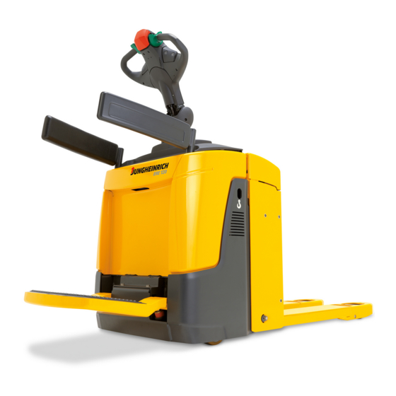
B Truck Description Application The industrial truck is a tiller operated electric pallet truck with a folding standing platform and side arms. It is designed for transporting goods on level surfaces. Open bottom pallets or pallets with transverse boards (provided that the boards are outside the perimeter of the load wheels) can be lifted.
-
Page 17: Travel Direction Definition
Travel direction definition The following determinations have been made for travel direction specification: Item Travel direction Left Drive direction Load direction Right…
-
Page 18: Assemblies And Functional Description
Assemblies and Functional Description Assembly Overview Item Component Item Component t Travel switch o CanDis t Tiller t Charge indicator t Key switch 10 t Folding operator platform o CanCode 11 o Folding side restraint o ISM 12 o Mains cable (on-board charger) t Emergency Disconnect (main Support wheel 13 t…
-
Page 19: Functional Description
Functional Description Safety Mechanisms An enclosed, smooth truck perimter with rounded edges ensures safe handling of the truck. The wheels are surrounded by a solid skirt. When released a gas pressure spring pushes the tiller up and activates braking. If the truck touches a person, the red collision safety switch changes the travel direction in pedestrian mode when travelling in drive direction with the platform and the side restraints folded up (o).
- Page 20
Tiller The driver steers with an ergonomic tiller. All travel and lift operations can be performed sensitively without having to reach. The tiller has a steer angle of 180°. Electrical system The truck has an electronic traction controller. The operating voltage of the truck’s electrical system is 24 volts. -
Page 21: Technical Specifications
The technical specifications comply with the German «Industrial Truck Data Sheet» Guidelines. Technical modifications and additions reserved. Performance data Description ERE 120 ERE C20 Q Rated capacity 2000 Q Rated capacity (support arm lift / mast lift) 2000 / 700…
-
Page 22: Dimensions
Dimensions ERE 120 1053…
- Page 23
ERE C20 1053 22 4 24 8 b1 1… - Page 24
Description ERE 120 Tiller height in travel position 1146/1428 Lowered fork height Rated lift b1/b2 Overall width Width across forks 510/540/670 Track width, front 338/368/498 Track width, rear s/e/l Fork dimensions 55/172/1150 Safety clearance Overall length (M/L) 1834/1906 Headlength (M/L) - Page 25
Description ERE C20 Tiller height in travel position 1146/1428 Lowered fork height Mast lift Support arm lift b1/b2 Overall width Width across forks Track width, front Track width, rear s/e/l Fork dimensions 60/187/1150 Safety clearance Overall length 1850 Length to fork face Ground clearance, centre of wheelbase 1)3)4) Aisle width for pallets 1000×1200… - Page 26
Aisle widths ERE 120 / ERE C20 (all dimensions in mm) 3)4) 1)3)4) 1)2)3) 2)3)4) Battery compartment L — Headlength l = 754 mm 1000 1756 1269 1000 1517 1954 1150 1906 1419 1200 1667 2154 1200 1956 1469 1200… -
Page 27: Weights
Weights Description ERE 120 Net weight excl. battery (M/L) 440/443 Axle loading, laden 1702/1043 front/rear + battery (L) Axle loading, unladen 155/590 front/rear + battery (L) Weights and axle loads vary depending on truck features. Description ERE C20 Net weight excl. battery…
-
Page 28: En Norms
EN norms Continuous sound pressure level – ERE 120 / ERE C20: 73 dB(A) in accordance with EN 12053 as harmonised with ISO 4871. The continuous sound pressure level is calculated according to standard procedures and takes into account the sound pressure level when driving, lifting and idling.
-
Page 29: Conditions Of Use
Conditions of use Ambient temperature – without cold store equipment: operating at -10°C to 40°C, see «Internal Operation Combined with Brief External or Cold Store Operation (t)» on page 13 – with cold store equipment: operating at -28°C to +25°C, see «Internal Operation in Cold Stores with Cold Store Equipment (o)»…
-
Page 30: Identification Points And Data Plates
Identification Points and Data Plates Warnings and notices such as capacity charts, strap points and data plates must be legible at all times. Replace if necessary. Indication Points ERE 120 Item Component Capacity Qmax Attachment points for lifting by crane…
-
Page 31: Data Plate
ERE C20 2000 Q max Q max Item Component Capacity Qmax Attachment points for lifting by crane Model name Battery data plate Data plate Serial number (etched into the truck chassis) Ergonomic lift capacity plate…
- Page 32
Data plate The illustration shows the standard version for EU member states. The data plate may differ in other countries. Item Description Item Description Type Year of manufacture Serial number Load centre (mm) Rated capacity (kg) Output Battery voltage (V) Min./max. -
Page 33: Truck Capacity Plate
Truck capacity plate The capacity plate (14) gives the maximum load-bearing capacity (Q) of the truck in kg assuming the load on the load handler is evenly distributed. Capacity plate, ergonomic lift(o) (ERE C20) 2000 Q max Q max Travelling with a raised load prohibited Max.
-
Page 34: C Transport And Commissioning
C Transport and Commissioning Lifting by crane WARNING! All persons involved in loading by crane must be trained Incorrect crane loading procedures due to untrained personnel can cause the truck to fall. There is a risk of injury to personnel and a risk of material damage to the truck. Loading must only be performed by specialist personnel trained for this purpose.
- Page 35
The truck can now be lifted by crane. -
Page 36: Remove The Transport Lock
Remove the transport lock The transport lock ensures that the truck is braked during transport without the mass of the battery. There is an instruction decal by the front cover for the transport lock (35). This must be removed once the battery has been installed. Remove the transport retainer Requirements –…
-
Page 37: Transport
Transport WARNING! Uncontrolled movement during transport Improper fastening of the truck and mast during transport can result in serious accidents. Loading is only to be carried out by specially trained staff. The specialist personnel must be instructed in the securing of loads on road vehicles and in the use of load- securing equipment.
-
Page 38: Using The Truck For The First Time
Using the Truck for the First Time WARNING! The use of unsuitable energy sources can be hazardous Rectified AC current will damage the assemblies (controllers, sensors, motors etc.) of the electronic system. Unsuitable cable connections (too long, insufficient wire cross-section) to the battery (tow cables) can overheat, setting the truck and battery on fire.
-
Page 40: D Battery — Servicing, Recharging, Replacement
D Battery — Servicing, Recharging, Replacement Safety Regulations Governing the Handling of Lead-Acid Batteries Maintenance personnel Batteries may only be charged, serviced or replaced by trained personnel. These operating instructions and the manufacturer’s instructions concerning batteries and charging stations must be observed when carrying out the work. Fire Protection Do not smoke and avoid naked flames when handling batteries.
- Page 41
The use of unsuitable batteries that have not been approved for the truck by Jungheinrich, can lead to a deterioration of the braking characteristics of the truck during energy recovery, causing considerable damage to the electric controller and resulting in serious danger to the health and safety of individuals. -
Page 42: Battery Types
The battery weights can be taken from the battery data plate. Batteries with non insulated terminals must be covered with a non slip insulating mat. ERE 120 Battery tray M Battery type Capacity (Ah) Min.
- Page 43
ERE C20 Battery tray S Battery type Capacity (Ah) Min. weight Max. dimensions (kg) (mm) 24 volt battery 2PzB 200 662X147X686 24 volt battery 2PzVB 170 657X147X686 24 volt battery 2PzVB 142 652X147X560 24 volt battery 2PzB 150 662 x 147 x 592 24 volt battery 2PzB 150 Lib.Silver 144 662 x 147 x 592… -
Page 44: Exposing The Battery
Exposing the battery WARNING! An unsecured truck can cause accidents Parking the truck on an incline or with a raised load handler is dangerous and is strictly prohibited. Park the truck on a level surface. In special cases the truck may need to be secured with wedges.
-
Page 45: Charging The Battery
Charging the battery WARNING! The gases produced during charging can cause explosions The battery gives off a mixture of oxygen and hydrogen (electrolytic gas) during charging. Gassing is a chemical process. This gas mixture is highly explosive and must not be ignited. Switch the charging station and truck off first before connecting/disconnecting the charging cable of the battery charging station to/from the battery connector.
-
Page 46: Charging The Battery With A Stationary Charger
Charging the battery with a stationary charger Charging the battery Requirements – Expose the battery, see «Exposing the battery» on page 43. Procedure • Disconnect battery connector (40) from truck connector. • Connect the battery connector (40) to charging cable (41) stationary charger.
-
Page 47: Charging The Battery With An On-Board Charger (O)
The on-board charger consisting of a battery charger and battery controller must not be opened. If faulty, contact the manufacturer’s customer service department. The charger must only be used for batteries supplied by Jungheinrich or other approved batteries provided it has been adapted by the manufacturer’s customer service department.
- Page 48
Flashing sequence / charging curve assignment (ELH 2415/2425/2435) Flashing sequence Selected charging curves (characteristics) Wet cell battery: PzS with 100 — 300 Ah Wet cell battery: PzM with 100 — 179 Ah Wet cell battery: PzS with pulse characteristic 200 — 400 Ah Wet cell battery: PzM with pulse characteristic 180 — 400 Ah… - Page 49
Mains frequency: 50 Hz / 60 Hz The mains connector of the charger (42) is integrated in the battery compartment (the illustration shows the battery compartment of the ERE 120). Charging the battery Requirements – Park the truck securely, see «Parking the truck securely» on page 65. - Page 50
Completing the battery charge, restoring the truck to operation NOTE If charging has been interrupted, the full battery capacity will not be available Requirements – Battery charging is complete. Procedure • Remove the mains connector from the socket and store it in the battery compartment with the cable. - Page 51
LED display (43) Green LED (charge status) Charging complete, battery full. (Charge interval, float or compensation charge). Slow flash Charging. Rapid flash Display at beginning of charge or after setting a new characteristic curve. Number of flash pulses corresponds to the characteristic curve set. -
Page 52: Battery Removal And Installation
Battery removal and installation WARNING! Accident risk during battery removal and installation Due to the battery weight and acid there is a risk of trapping or scalding when the battery is removed and installed. Note the «Safety regulations for handling acid batteries» section in this chapter. Wear safety shoes when removing and installing the battery.
-
Page 53: Removing The Battery From The Top
Removing the battery from the top Battery removal Requirements – Park the truck securely, see «Parking the truck securely» on page 65. – Expose the battery, see «Exposing the battery» on page 43. Procedure • Remove the battery panel on trucks with a protective grille (o). •…
-
Page 54: Removing The Battery From The Side
Removing the battery from the side CAUTION! Trapping hazard Trapping hazard when removing and installing the battery. When removing and installing the battery do not put your hands between the battery and the chassis. Battery removal Requirements – Park the truck securely, see «Parking the truck securely»…
-
Page 56: E Operation
E Operation Safety Regulations for the Operation of the Forklift Truck Driver authorisation The truck may only be used by suitably trained personnel, who have demonstrated to the proprietor or his representative that they can drive and handle loads and have been authorised to operate the truck by the proprietor or his representative.
- Page 57
Hazardous area WARNING! Risk of accidents/injury in the hazardous area of the truck A hazardous area is defined as the area in which people are at risk due to travel or lifting operations of the truck, its load handler or the load. This also includes the area within reach of falling loads or lowering/falling operating equipment. -
Page 58: Displays And Controls
Displays and Controls 52,53,54 7, 9…
- Page 59
Item Control /Display Function t – Controls the direction of travel as well as Travel switch the travel speed. t – Set to brake zone (B) (see «Brakes» on Tiller page 77): The truck brakes mechanically. – Set to travel zone (F) (see «Brakes» on page 77): The mechanical brake is released and the truck is ready for operation. - Page 60
Item Control /Display Function t Safety feature Collision safety switch – Pedestrian mode: When applied, the truck travels for approx. 3 seconds in the fork direction. The parking brake then applies. The truck remains switched off until the travel switch is set to neutral. –… -
Page 61: Battery Discharge Monitor
Battery discharge monitor The standard setting for the battery discharge indicator / discharge monitor is based on standard batteries. When using maintenance-free or special batteries, the display and cut-out points of the battery discharge monitor must be set by manufacturer’s service department. If this adjustment is not made, the battery may become damaged due to deep discharge.
-
Page 62: Starting Up The Truck
Starting up the truck Checks and Operations to Be Performed Before Starting Daily Work WARNING! Damage and other truck or attachment (optional equipment) defects can result in accidents. If damage or other truck or attachment (optional equipment) defects are discovered during the following checks, the truck must be taken out of service until it has been repaired.
-
Page 63: Preparing The Truck For Operation
Preparing the truck for operation Switching on the truck Requirements – For checks and operations to be performed before starting daily operation, see «Checks and Operations to Be Performed Before Starting Daily Work» on page 61. Procedure • For rider mode, fold out the operator platform (10) and the side arms (o) (11). •…
- Page 64
9, 52 54, 56… -
Page 65: Checks And Operations To Be Carried Out When The Truck Is Operational
Checks and operations to be carried out when the truck is operational WARNING! Risk of accident due to damage to or other defects in the truck and optional features If damage or other truck or attachment (optional equipment) defects are discovered during the following checks, the truck must be taken out of service until it has been repaired.
-
Page 66: Parking The Truck Securely
Parking the truck securely WARNING! An unsecured truck can cause accidents Do not leave an unsecured truck. Park the truck securely when leaving it. Exception: If the operator intends to remain in the immediate vicinity and is leaving the truck for only a short while, the applied parking brake is sufficient to hold the truck, see page 78.
- Page 67
Parking the truck securely Procedure • Park the truck on a level surface. • Fully lower the load handler. • Press the “Lower load handler” button. • Using the tiller, set the drive wheel to «forward travel». • Switch off the truck, to do this: •… -
Page 68: Industrial Truck Operation
Industrial Truck Operation Safety regulations for truck operation Travel routes and work areas Only use lanes and routes specifically designated for truck traffic. Unauthorised third parties must stay away from work areas. Loads must only be stored in places specially designated for this purpose. The truck must only be operated in work areas with sufficient lighting to avoid danger to personnel and materials.
-
Page 69: How To Act In Hazardous Situations
the lift shaft. Persons riding in the lift with the forklift truck must only enter the lift after the truck has come to a rest and must leave the lift before the truck. The driver must ensure that the loading ramp / dock cannot move or come loose during loading / unloading.
-
Page 70: Emergency Disconnect
Emergency Disconnect CAUTION! Applying maximum braking can result in accidents Applying the Emergency Disconnect switch during travel will cause the truck to decelerate to a halt at maximum force. This may cause the load to slide off the load handler. There is a higher risk of accidents and injury. Do not use the Emergency Disconnect switch as a service brake.
- Page 71
Press the Emergency Disconnect switch Procedure • Press the Emergency Disconnect (8). All electrical functions are deactivated. The truck brakes to a halt. Press the Emergency Disconnect switch on in emergencies. Releasing the Emergency Disconnect switch Procedure • Pull the Emergency Disconnect switch (8) to unlock it. All electrical functions are enabled and the truck is operational again (provided the truck was operational before the Emergency Disconnect was pressed). -
Page 72: Automatic Braking
Automatic braking When the tiller is released, it returns automatically to the upper brake zone (B) and the brakes are applied automatically. WARNING! Risk of collision due to a defective tiller Operating the truck with a defective tiller can lead to collisions with persons or objects. If the tiller returns to the brake position slowly or not at all, the truck must be taken out of service until the cause of this fault is be rectified.
-
Page 73: Travel
Travel WARNING! Collision hazard when operating the truck Collisions with personnel and equipment can result if the truck is operated with open panels. Do not operate the truck unless the panels and covers are closed and properly locked. When travelling through swing doors etc. make sure that the doors do not activate the collision safety button.
- Page 74
– Travel in pedestrian mode – Travel in rider mode Travelling in pedestrian mode Requirements – Start up the truck, see «Starting up the truck» on page 61 Procedure • Swing in both folding side arms (11) (o). Both side arms must always be folded in, otherwise all functions are deactivated (E-1926). - Page 75
Travelling is inhibited when the operator platform is vacated and the side arms are not folded out. ERE 120: If the standing platform is occupied and the side arms are not folded out, the truck can only be operated at reduced speed. - Page 77
4.5.1 Changing direction during travel CAUTION! Danger when changing direction during travel Changing direction during travel causes the truck to decelerate sharply. When the truck changes direction, it can start travelling at high speed in the opposite direction unless the travel switch is released in time. After setting off in the opposite direction, apply the travel switch gently or not at all. -
Page 78: Steering
Steering Procedure • Move the tiller (6) to the left or right. The truck is steered in the required direction. Brakes WARNING! Accident risk The brake pattern of the truck depends largely on the ground conditions. The operator must take into account the travel route conditions when braking. Brake with care to prevent the load from slipping.
- Page 79
4.7.1 Braking with the service brake Procedure • Move the tiller (6) up or down to one of the brake zones (B). The truck brakes to a halt regeneratively via the service brake. When braking regeneratively, energy is returned to the battery, ensuring a longer service time. -
Page 80: Load Handler Raise/Lower
Load handler raise/lower WARNING! Accident risk when lifting and lowering Other people can be injured in the truck’s hazardous area. The hazardous area is defined as the area in which people are at risk from the movement of the truck including the load handler, etc. This also includes areas which can be reached by falling loads, operating equipment, etc.
- Page 81
4.8.1 Raising the load handler Requirements – Prepare truck operation, «Preparing the truck for operation» on page 62. 49 50 Procedure • Press the “Raise load handler ” button (50) until you reach the desired lift height. NOTE Risk of material damage to the hydraulic unit When the mechanical end stop of the load has been reached, release the «Raise load handler»… -
Page 82: Lifting, Transporting And Depositing Loads
Lifting, transporting and depositing loads WARNING! Unsecured and incorrectly positioned loads can cause accidents. Before lifting a load unit, the driver must make sure that it has been correctly palletised and does not exceed the truck’s capacity. Instruct other people to move out of the hazardous area of the truck. Stop working with the truck if people do not leave the hazardous area.
- Page 83
4.9.1 Raising a load Requirements – Load correctly palletised. – Load weight matches the truck’s capacity. – Load handler evenly loaded for heavy loads. Procedure • Drive the truck carefully up to the pallet. • Drive the load handler slowly into the pallet until the pallet is against the back of the load handler (see graphic to the right). - Page 84
4.9.2 Transporting a load Requirements – Load raised correctly. – ERE 120: Raise the forks completely from the ground to transport correctly (approx. 150 — 200 mm above the ground). – ERE C20: Raise the forks completely from the ground to transport correctly (approx. 150 — 500 mm above the ground ). - Page 85
4.9.3 Depositing a load CAUTION! Loads must not be set down on transport or escape routes, in front of safety installations or factory equipment that must be accessible at all times. Requirements – Storage location suitable for storing the load. Procedure •… -
Page 86: Ergonomic Lift (O) (Ere C20)
4.10 Ergonomic Lift (o) (ERE C20) For lifting and lowering, the truck is equipped with support arm lift (initial lift) with the maximum lift capacity and mast lift (high lift) with a lower lift capacity, see «Truck capacity plate» on page 32. Raises the load handler When the «Load handler lift»…
- Page 87
4.10.1 Use as a Lift Work Table The load handler can remain in a raised position to be used as a lift work table when the truck is switched off, provided the operator is close to the truck. Immediate vicinity of the truck is when the operator is able to respond to malfunctions or attempts to use the truck by unauthorised persons immediately. -
Page 89: Troubleshooting
Troubleshooting This chapter enables the operator to localize and rectify basic faults or the results of incorrect operation himself. When trying to locate a fault, proceed in the order shown in the remedy table. If, after carrying out the following remedial action, the truck cannot be restored to operation or if a fault in the electronics system is displayed with a corresponding error code, contact the manufacturer’s service department.
-
Page 90: Truck Does Not Start
Truck does not start Possible cause Corrective measures Battery connector not plugged in. Check the battery connector and connect if necessary. Emergency disconnect switch pressed Unlock the emergency disconnect switch Key switch set to O Set the key switch to “I” Battery charge too low Check battery charge, charge the battery if necessary…
-
Page 91: Load Cannot Be Lifted
Load cannot be lifted Possible cause Corrective measures Truck not operational Carry out all measures listed under “Truck does not start” Hydraulic oil level too low Check the hydraulic oil level, see page 142 Battery discharge monitor has switched Charge the battery, see page 44 Faulty fuse Check the fuses, see page 143 Excessive load…
-
Page 92: Operating The Truck Without Its Own Drive System
Operating the truck without its own drive system With the right optional equipment (o) it is possible to switch the truck to emergency operation via the GF60 service key: The brakes are released electrically and the truck can move without its own drive system, see «Emergency operation with service key GF60″…
- Page 93
WARNING! Only return the truck to service when you have identified and rectified the fault. -
Page 94: Optional Equipment
Optional equipment Emergency operation with service key GF60 WARNING! The truck can move accidentally when the brake is released The GF60 service key must not remain on the truck during normal operation. The service key should only be used by an authorised person (e.g. warehouse manager).
- Page 95
Parking the truck securely Procedure • Set the key switch to the “0” position and remove the key. When you switch back from level 2 to level 1 the bar returns to its original position. The brake is now activated again. GF 30 The GF30 key without a bar is designed for normal truck operation. -
Page 96: Cancode Keypad (O)
CanCode Keypad (o) 7.2.1 Code lock The code lock allows a user or group of users to assign an individual user code. Travel programs can also be assigned to the individual user codes. The user code is configured with a master code and is described in the following sections in this chapter.
- Page 97
The keypad consists of 10 digit keys, a Set key (61) and a o key (63). Digit keys The digit keys are used to enter the user or master code and select the travel program. The green LEDs of the digit keys 1, 2 and 3 (58, 59, 60) show the travel program setting. - Page 98
7.2.2 Preparing the truck for operation with the keypad (CanCode) Preparing the truck for operation by entering a valid operator code Procedure • Pull the Emergency Disconnect to unlock it, see «Emergency Disconnect» on page 69. The LED (62) lights up red. •… - Page 99
7.2.4 Changing the master code To change the length of the master code you must follow the procedure in «Choose length of the new master code (4-6 digit) and add user codes», see «Choose length of the new master code (4-6 digit) and add user codes» on page 107. If there are still user codes stored in the code lock, the master code to be changed must be the same length as the saved user codes. - Page 100
Error displays changing the master code For the following events the LED (62) flashes red: Cause Remedy – New master code is already – Switch off the truck, see «Switching off the truck occupied by a user code with the keypad (CanCode)» on page 97. –… - Page 101
7.2.5 Add operator code Requirements – To prepare the truck for operation, see «Preparing the truck for operation with the keypad (CanCode)» on page 97. Procedure • Press the O key (63). • Enter the valid master code with the digit keys. When you enter the valid master code the LED (62) flashes green. - Page 102
Error displays adding a user code For the following events the LED (62) flashes red: Cause Remedy – The user code entered is not – Switch off the truck, see «Switching off the truck the same length as the with the keypad (CanCode)» on page 97. master code –… - Page 103
7.2.6 Change operator code Requirements – To prepare the truck for operation, see «Preparing the truck for operation with the keypad (CanCode)» on page 97. Procedure • Press the O key (63). • Enter the valid master code with the digit keys. When you enter the valid master code the LED (62) flashes green. - Page 104
Error displays changing a user code For the following events the LED (62) flashes red: Cause Remedy – The user code entered is not – Switch off the truck, see «Switching off the truck the same length as the with the keypad (CanCode)» on page 97. master code –… - Page 105
7.2.7 Delete individual user codes Requirements – To prepare the truck for operation, see «Preparing the truck for operation with the keypad (CanCode)» on page 97. Procedure • Press the O key (63). • Enter the valid master code with the digit keys. When you enter the valid master code the LED (62) flashes green. - Page 106
Error displays deleting individual user codes For the following events the LED (62) flashes red: Cause Remedy – The user code entered is not – Switch off the truck, see «Switching off the truck the same length as the with the keypad (CanCode)» on page 97. master code –… - Page 107
7.2.8 Delete all user codes, Requirements – To prepare the truck for operation, see «Preparing truck operation with keypad (CanCode)» on page 97. Procedure • Press the O key (63). • Enter the valid master code with the digit keys. When you enter the valid master code the LED (62) flashes green. - Page 108
7.2.9 Choose length of the new master code (4-6 digit) and add user codes The master code is factory set to a four-digit entry: If necessary, the four-digit master code can be changed to a five or six-digit entry. Before the master code length can be changed, all user codes must be deleted. - Page 109
7.2.10 Setting the automatic truck cutout (timeframe) Requirements – To prepare the truck for operation, see «Preparing the truck for operation with the keypad (CanCode)» on page 97. Procedure • Press the O key (63). • Enter the valid master code with the digit keys. When you enter the correct master code the LED (62) flashes green. - Page 110
Cause Remedy – Cutout time entered is out of – Switch off the truck, see «Switching off the truck range with the keypad (CanCode)» on page 97. – Enter the time again while making sure it is within range. Fixed cutout time (o) An automatic truck cutout is factory-set. - Page 111
7.2.11 Assigning the travel program The travel programs are fixed to the user code and can be released or blocked with a configuration code. The configuration code can also be used to assign a starting travel program to each user code. The starting travel program is the travel program that is activated when the truck is switched on and is displayed by the (58,59,60) LEDs. - Page 112
Specifying a configuration code: Setting Description – Travel program 1 is blocked for the user code selected 1st digit – Travel program 1 is enabled for the user code selected – Travel program 2 is blocked for the user code selected 2nd digit –… - Page 113
Adapting the travel program configuration to the user code Procedure • Press the O key (63). • Enter the valid master code with the digit keys. When you enter the valid master code the green LED (62) flashes green. • Enter the parameters 0-2-4 with the digit keys. •… - Page 114
Error displays configuring the travel programs For the following events the LED (62) flashes red: Cause Remedy – Blocked travel program – Switch off the truck, see «Switching off the truck defined as start travel with the keypad (CanCode)» on page 97. program –… -
Page 115: Setting The Truck Parameters With Cancode
Setting the truck parameters with CanCode CAUTION! Faulty entry Without CanDis only CanCode internal parameters can be changed. Traction controller parameters can only be changed with CanDis, without CanDis the settings must be performed by the manufacturer’s service department. CAUTION! Altering settings for the travel and hydraulic functions can result in accidents Increasing the settings for travel and hydraulic functions can result in accidents.
- Page 116
To continue setting, confirm with the Set key (61) again. Saving travel parameters Requirements – Enter all parameters. Procedure • Run «SaveParameters» by pressing 1-2-3-Set. • Confirm with the O key (63). -
Page 117: Parameters
0256 Acceleration 0 — 9 Platform folded (0.13 — 1.88 m/s 0.67 m/s out, side arms folded out 0264 ERE 120: Maximum speed in drive 0 — 9 direction using travel (4.5 — 9.0 km/h) 6.0 km/h switch ERE C20:…
- Page 118
0272 Acceleration 0 — 9 Platform folded (0.13 — 1.88 m/s 1.08 m/s out, side arms folded out 0280 ERE 120: Maximum speed in drive 0 — 9 direction using travel (4.5 — 9.0 km/h) 8.5 km/h switch ERE C20:… - Page 119
0288 Acceleration 0 — 9 Platform folded (0.13 — 1.88 m/s 1.62 m/s out, side arms folded out 0296 ERE 120: Maximum speed in drive 0 — 9 direction using travel (4.5 — 9.0 km/h) 8.5 km/h switch ERE C20:… - Page 120
Battery parameters Function Range Standard Comments setting 1377 Battery type 0 — 5 0 = Normal (wet) (normal / high 1 = High performance performance / dry) (wet) 2 = Dry (maintenance-free) 3 = US «Flat Plate» type 4 = US «Pallet Pro» type 5 = US «Tubular Plate»… - Page 121
Function Range Standard Comments setting 1388 ELH charger 0 — 6 characteristic curve No charging function 1 = PzS wet cell batteries 100 — 300 Ah and PzM batteries from 0 — 179 Ah 2 = PzS wet cell batteries with pulse characteristics 200 — 400 Ah and PzM batteries from 180 -… -
Page 122: Setting The Battery Parameters With Cancode
Setting the Battery Parameters with CanCode WARNING! Altering parameters cause accidents Altering settings cause accidents. This requires greater attention on the part of the operator The following example shows the parameter setting for the battery type (parameter 1377) to «dry — maintenance-free».
- Page 123
Testing an altered parameter Requirements – The parameter is now saved. Procedure • Press the O key (63). • Enter the master code. • Enter the four-digit parameter number «1377» and confirm with the Set key. • Enter sub index «2» and confirm with the Set key. The parameter with subindex are displayed alternately with the current reading. -
Page 124: Set Elh 2415 / 2425 / 2435 Charger Characteristics With Cancode
Set ELH 2415 / 2425 / 2435 Charger Characteristics with CanCode Parameter setting example The following example shows the charging characteristics parameter setting for a maintenance-free battery with 201 — 300 Ah. Requirements – CanCode and CanDis are available. Procedure •…
- Page 125
The parameter with sub index are displayed alternately with the current reading. E.g. (1388-2<->0000-5) corresponds to the charging characteristics for the maintenance-free battery with 201 — 300 Ah. • Press the O key. The parameter has now been checked. -
Page 126: Candis Display Instrument (O)
CanDis Display Instrument (o) The instrument indicates: Battery charge display (on board charger only) LED bars for battery charge status «Warning» symbol (yellow), Battery charge recommended «Stop» symbol (red); lift cutout, Battery charge essential No symbol when battery type set to normal or enhanced performance wet cell battery «T»…
-
Page 127: Ism Access Module (O)
7.7.1 Discharge monitor function The discharge limit has been reached when the «Stop» symbol (67) lights up. When the discharge monitor function is activated lifting operations are disabled. Travel and lowering are still possible. Lifting is only enabled again when the battery is 70% charged.
-
Page 128: F Industrial Truck Maintenance
F Industrial Truck Maintenance Operational Safety and Environmental Protection The checks and servicing operations contained in this chapter must be performed in accordance with the maintenance checklist service intervals. WARNING! Risk of accidents and component damage Any modification to the truck, in particular the safety mechanisms, is prohibited. Exception: Operating companies should only make changes or have changes made to powered industrial trucks if the manufacturer is no longer operating in the field and there is no successor to the business;…
-
Page 129: Maintenance Safety Regulations
Maintenance Safety Regulations Maintenance and repair personnel The manufacturer has a service department specially trained for these tasks. A maintenance contract with the manufacturer will ensure trouble-free operation. Truck maintenance and repair work must only be carried out by specially trained personnel.
-
Page 130: Working On The Electrical System
Working on the electrical system WARNING! Electrical current can cause accidents Make sure the electrical system is voltage-free before starting work on it. The capacitors in the controller must be completely discharged. The capacitors are completely discharged after approximately 10 minutes. Before starting maintenance on the electrical system: Only suitably trained electricians may operate on the truck’s electrical system.
-
Page 131: Hydraulic System
Hydraulic system WARNING! Leaky hydraulic systems can result in accidents Hydraulic oil can escape from leaky and faulty hydraulic systems. Report any defects immediately to your supervisor. Mark defective truck and take out of service. Do not return the industrial truck to service until you have identified and rectified the fault.
-
Page 132: Lift Chains
Lift Chains WARNING! Non-lubricated and incorrectly cleaned lift chains can cause accidents Lift chains are safety-critical parts. They must not contain any serious contamination. Lift chains and pivot pins must always be clean and well lubricated. Lift chains should only be cleaned with paraffin derivatives e.g. petroleum or diesel fuels.
-
Page 133: Lubricants And Lubrication Schedule
Lubricants and Lubrication Schedule Handling consumables safely Handling consumables Consumables must always be handled correctly. Follow the manufacturer’s instructions. WARNING! Improper handling is hazardous to health, life and the environment Consumables can be flammable. Keep consumables away from hot components and naked flames. Always keep consumables in prescribed containers.
- Page 134
WARNING! Improper handling of oils can be hazardous Oils (chain spray / hydraulic oil) are flammable and poisonous. Dispose of used oils in accordance with regulations. Store used oil safely until it can be disposed of in accordance with regulations. Do not spill oil. -
Page 135: Lubrication Schedule
Lubrication Schedule 0,7l 0,55 l g Contact surfaces Cold Store Application s Grease nipple b Transmission oil filler neck a Transmission oil drain plug Transmission oil overflow and dipstick Hydraulic oil filler neck 1 Compound ratio for cold store usage 1:1…
-
Page 136: Consumables
The Jungheinrich hydraulic oil can only be obtained from the Jungheinrich service department. The use of named alternative hydraulic oils is not prohibited but may lead to a decline in functionality. The Jungheinrich hydraulic oil may be mixed with one of the named alternative hydraulic oils.
-
Page 137: Maintenance And Repairs
Maintenance and repairs Prepare the truck for maintenance and repairs All necessary safety measures must be taken to avoid accidents when carrying out maintenance and repairs. The following preparations must be made: Procedure • Park the truck securely, see «Parking the truck securely» on page 65. •…
-
Page 138: Front Cover Disassembly
Front cover disassembly Front cover disassembly Procedure • Fold down the operator platform (10). • Release the compartment panel latch using a spanner (width
and expose the panel latch. • Release the panel latch (71) using a spanner (width 8). •…
-
Page 139: Lifting And Jacking Up The Truck Safely
Lifting and jacking up the truck safely WARNING! Lifting and jacking up the truck safely In order to raise the truck, the lifting gear must only be secured to the points specially provided for this purpose. You may only work under a raised load handler if it has been secured with a sufficiently strong chain or the fastening bolt.
-
Page 140: Cleaning
Cleaning 4.4.1 Cleaning the truck CAUTION! Fire hazard Do not use flammable liquids to clean the industrial truck. Disconnect the battery before starting cleaning work. Carry out all necessary safety measures to prevent sparking before cleaning (e.g. by short-circuiting). CAUTION! Risk of component damage when cleaning the truck Cleaning with a pressure washer can result in malfunctions due to humidity.
- Page 141
Cleaning the truck Requirements – Prepare the truck for maintenance and repairs (see «Prepare the truck for maintenance and repairs» on page 136). Tools and Material Required – Water-based solvents – Sponge or cloth Procedure • Clean the surface of the truck with water-based solvents and water. Use a sponge or cloth to clean. - Page 142
4.4.2 Cleaning the electrical system assemblies CAUTION! Risk of electrical system damage Cleaning the assemblies (controllers, sensors, motors etc.) of the electronic system with water can damage the electrical system. Do not clean the electrical system with water. Clean the electrical system with weak suction or compressed air (use a compressor with a water trap) and not a conductive, anti-static brush. -
Page 143: Replacing The Drive Wheel
Replacing the drive wheel The drive wheel must only be replaced by authorised service personnel. Checking the hydraulic oil level Check oil level Requirements – Lower the load handler. – Prepare the truck for maintenance and repairs, see «Prepare the truck for maintenance and repairs»…
-
Page 144: Checking Electrical Fuses
Checking electrical fuses Check fuses Requirements – Truck prepared for maintenance and repairs, see «Prepare the truck for maintenance and repairs» on page 136. – Front cover removed, see «Front cover disassembly» on page 137. Procedure • Check the fuse ratings against the table and replace if necessary. The fuses are now checked.
- Page 145
Item Component To protect Rating (A) 9F22 Control fuse 2 (after main contactor) Display / battery hour meter Control fuse 1 (before main contactor) Spare Spare for option Drive / lift motor main fuse… -
Page 146: Restoring The Truck To Service After Maintenance And Repairs
Restoring the truck to service after maintenance and repairs Procedure • Thoroughly clean the truck, see «Cleaning the truck» on page 139. • Lubricate the truck according to the lubrication schedule, see «Lubrication Schedule» on page 134. • Clean the battery, grease the terminals and connect the battery. •…
-
Page 147: Decommissioning The Industrial Truck
Decommissioning the Industrial Truck If the truck is to be out of service for more than a month, it must be stored in a frost- free and dry room. All necessary measures must be taken before, during and after decommissioning as described hereafter. When the truck is out of service it must be jacked up so that all the wheels are clear of the ground.
-
Page 148: Restoring The Truck To Service After Decommissioning
Restoring the truck to service after decommissioning Procedure • Thoroughly clean the truck, see «Cleaning» on page 139. • Lubricate the truck according to the lubrication schedule, see «Lubrication Schedule» on page 134. • Clean the battery, grease the terminals and connect the battery. •…
-
Page 149: Safety Tests To Be Performed At Intervals And After Unusual Incidents
Safety tests to be performed at intervals and after unusual incidents The truck must be inspected at least annually (refer to national regulations) or after any unusual event by a qualified inspector. The manufacturer offers a safety inspection service which is performed by personnel specifically trained for this purpose.
-
Page 150: Servicing And Inspection
Servicing and Inspection WARNING! Lack of maintenance can result in accidents Failure to perform regular servicing can lead to truck failure and poses a potential hazard to personnel and equipment. Thorough and expert servicing is one of the most important requirements for the safe operation of the industrial truck.
-
Page 151: Maintenance Checklist
Maintenance checklist 10.1 Operating Company 10.1.1 Standard Equipment Braking W A B C Test brakes. Electrical W A B C Test warning and safety devices in accordance with operating instructions. Test emergency disconnect switch. Power supply W A B C Check battery cable connections are secure, check for dirt and grease terminals if necessary.
- Page 152
On-board charger 35A Battery charger W A B C Check mains connector and mains cable. Standard on-board charger Battery charger W A B C Check mains connector and mains cable. -
Page 153: 10.2 Customer Service
10.2 Customer Service 10.2.1 Standard Equipment Braking W A B C Test brakes. Check the air gap of the magnetic brake. Electrical W A B C Check cables and motor mounting are secure. Test warning and safety devices in accordance with operating instructions.
- Page 154
Chassis and Superstructure W A B C Check chassis and screw connections for damage. Check doors and/or covers. Check labels are legible, complete and make sense. Test the operator platform and check for damage. Check operator mat and steps are non-slip and damage-free. Hydraulic Operations W A B C Test «hydraulic»… - Page 155
Automatic crawl speed Travel W A B C Check that sensors/switches are secured, not damaged, clean and operational. Battery refill system Power supply W A B C Test battery refill system and check for leaks. On-board charger 35A Battery charger W A B C Check mains connector and mains cable. - Page 156
Ergonomic lift Hydraulic Operations W A B C Test the lift sensors in the mast and initial lift and check for damage. Check settings and wear levels of slide pieces and stops and adjust the slide pieces if necessary. Check load chain setting and tension if necessary. Check lateral clearance of the mast connections and the fork carriage. - Page 158
A Traction Battery Appendix Contents Traction Battery Appendix…………Correct Use and Application…………..Data plate ………………..Safety Instructions, Warning Indications and other Notes ……. Lead acid batteries with armour plated cells and liquid electrolyte..Description………………..Operation………………..Servicing lead-acid batteries with armour plated cells……PzV and PzV-BS lead-acid batteries with sealed armour plated cells.. -
Page 159: Correct Use And Application
Correct Use and Application Failure to observe the operating instructions, carrying out repairs with non-original spare parts, tampering with the battery or using electrolyte additives will invalidate the warranty. Observe the instructions for maintaining the safety rating during operation for batteries in accordance with Ex I and Ex II (see relevant certification).
-
Page 160: Safety Instructions, Warning Indications And Other Notes
Safety Instructions, Warning Indications and other Notes Used batteries must be treated as hazardous waste. These batteries are marked with the recycling symbol and the sign showing a crossed-out rubbish bin, and should not be disposed of with ordinary household waste. waste.
-
Page 161: Lead Acid Batteries With Armour Plated Cells And Liquid Electrolyte
Lead acid batteries with armour plated cells and liquid electrolyte Description Jungheinrich traction batteries are lead acid batteries with armour plated cells and liquid electrolyte. The names of the traction batteries are PzS, PzB, PzS Lib and PzM. Electrolyte The rated density of the electrolyte assumes a temperature of 30°C and the rated electrolyte level is fully charged.
-
Page 162: Operation
Operation 4.2.1 Commissioning unfilled batteries The operations required must be carried out by the manufacturer’s customer service department or a customer service organisation authorised by the manufacturer. 4.2.2 Commissioning filled and charged batteries Checks and operations to be performed before starting daily work Procedure •…
- Page 163
4.2.4 Charging the battery WARNING! The gases produced during charging can cause explosions The battery gives off a mixture of oxygen and hydrogen (electrolytic gas) during charging. Gassing is a chemical process. This gas mixture is highly explosive and must not be ignited. Always disconnect the charger and truck before connecting or disconnecting the charger and battery. - Page 164
The electrolyte temperature rises by approx. 10 K during charging. Charging should therefore only begin when the electrolyte temperature is below 45°C. The electrolyte temperature of batteries must be at least +10°C before charging. Otherwise the battery will not charge correctly. Below 10°C the battery is insufficiently charged with standard charging systems. -
Page 165: Servicing Lead-Acid Batteries With Armour Plated Cells
Servicing lead-acid batteries with armour plated cells Water quality The quality of the water used to fill up electrolyte must correspond to purified or distilled water. Purified water can be produced through distillation or ion exchangers and is then suitable for the production of electrolyte. 4.3.1 Daily –…
-
Page 166: Pzv And Pzv-Bs Lead-Acid Batteries With Sealed Armour Plated Cells
PzV and PzV-BS lead-acid batteries with sealed armour plated cells Description PzV batteries are sealed batteries with fixed electrolytes, to which no water can be added over the entire lifespan of the battery. Relief valves are used as plugs which are destroyed when opened.
-
Page 167: Operation
Operation 5.2.1 Commissioning Checks and operations to be performed before starting daily work Procedure • Make sure the battery is in physically good condition. • Make sure the terminals are correct (positive to positive and negative to negative) and check that contacts on the battery terminal conducting system are secure. •…
- Page 168
NOTE Charging the battery incorrectly can result in material damage. Incorrect battery charging can result in overloading of the electric wires and contacts, hazardous gas formation and electrolyte leakage from the cells. Always charge the battery with DC current. All DIN 41773 charging procedures are permitted in the format approved by the manufacturer. - Page 169
Charging the battery Requirements – Electrolyte temperature between +15°C and 35°C Procedure • Open or take off the tray lid or covers from the battery compartment. • Connect the battery to the switched off charger, ensuring the terminals are connect (positive to positive and negative to negative). -
Page 170: Servicing Pzv And Pzv-Bs Lead-Acid Batteries With Sealed Armour Plated Cells
Servicing PzV and PzV-BS lead-acid batteries with sealed armour plated cells Do not add water! 5.3.1 Daily – Charge the battery after each discharge. 5.3.2 Weekly – Visually inspect for dirt and physical damage. 5.3.3 Every three months – Measure and record the overall voltage. –…
-
Page 171: Aquamatik Water Replenishment System
Aquamatik water replenishment system Water replenishment system design > 3 m Water container Tap connection with ball cock Flow indicator Shut-off cock Locking coupling Battery lock connector…
-
Page 172: Functional Description
Functional Description The Aquamatik water replenishment system is used to adjust the rated electrolyte level automatically on traction batteries for industrial trucks. The battery cells are interconnected through hoses and are attached to the water supply (e.g. water container) through a plug connection. When the shut-off cock is opened all the cells are filled with water.
-
Page 173: Filling Time
Filling time The filling time for a battery depends on the electrolyte level, the ambient temperature and the filling pressure. Filling ends automatically. The water supply line must be disconnected from the battery when the water has been filled. Water quality The quality of the water used to fill up electrolyte must correspond to purified or distilled water.
-
Page 174: Cleaning Measures
Cleaning measures The plug systems must only be cleaned with purified water in accordance with DIN 43530-4. No parts of the plugs must come into contact with solvent-based materials or soap. 6.10 Service mobile vehicle Mobile water filling vehicle with pump and filling gun to fill individual cells. The immersion pump in the container generates the necessary filling pressure.
-
Page 175: Electrolyte Circulation
Electrolyte circulation Functional Description Electrolyte circulation ensures the supply of air during charging to mix the electrolyte, thereby preventing any acid layer, shortening the charge time (charge factor approx. 1.07) and reducing the formation of gas during charging. The charger must be suitable for the battery and electrolyte circulation.
- Page 176
NOTE If an installed electrolyte circulation system is seldom used or not used at all, or if the battery is subjected to severe temperature fluctuations, the electrolyte may flow back into the hose system. Attach a separate coupling system to the air inlet line, such as: locking coupling on the battery side and through-coupling on the air supply side. -
Page 177: Cleaning Batteries
Cleaning batteries Batteries and trays must be cleaned in order to – maintain cell insulation and protect cells from ground or external conductive parts. – Avoid damage from corrosion and stray currents. – Avoid excessive and varying automatic discharge of the individual cells or block batteries due to stray currents.
- Page 178
Cleaning the battery with a high pressure cleaner Requirements – Cell connectors tight, plugged in securely – Cell plugs closed Procedure • Follow the high pressure cleaner’s user instructions. • Do not use any cleaning additives. • Observe the permissible cleaning device temperature setting of 140°C. This generally ensures that the temperature does not exceed 60°C at a distance of 30cm behind the outlet nozzle. -
Page 179: Storing The Battery
Storing the battery NOTE The battery should not be stored for longer than 3 months without charging as otherwise it will no longer be functional. If the battery is to be taken out of service for a long period, it should be stored fully charged in a dry room protected from frost.
Does anybody knows what code PRE OP stands for?
Showing items 1 — 11 of 11 results.
Sort messages by:
Okay! I´ve sent you an email
Okay! I´ve sent you an email
Thanks for your quick reply!
Do you have an electric schematics for this EJE116 (2007)?
I have to do some measurements.
13 Disable Watchdog field
faulty
F, H CONTROLLER Replace components Travel no function
14 — Main contactor
notclosed
— Field power stage
cannot be switched on
(DC)
F, H,
F-AC, H-AC
CONTROLLER/
MAIN CONTACTOR
Check wire connection; check main
contactor; check charging connection,
Check field supply fuse,
Replace component.
No travel, hydraulics
Warning symbol
Flashing warning (Else-Check).
15 Disable field faulty;
Illegal address (for AC)
F, H,
F-AC, H-AC
L
CONTROLLER Replace controlpart; replace
component
Travel no function
Hi guys,
I´ve got a EJE116 with a AS2405 box.
Blinking code: 15 and 13
Anyone knows the meaning?
Thanks in advance!
The print in the steering tiller has his voltage, i ordered a new print. So it should work when i install that one. Thx for the info.
Yes, if your saying the steering head or we call the steering tiller. It is part of the can bus.
Control is dead or not Voltage in control.
It fell off a truck, and i wanted to test if it still works, but what you say makes sense. although i thought i connected everything again but i ll have to check it over. When the print in the steering rudder is broken will it also show this error? thx for the reply.
Did you replace any parts recently? This code means it didnt see all the can bus components, controller, tiller head, display, keypad(if installed) Diagnostic port.
Having trouble using the Discussion Forums? Contact us for help.
Forkliftaction.com accepts no responsibility for forum content and requires forum participants to adhere to the rules. Click here for more information.

![]()
Jungheinrich System Error Codes list.pdf
Adobe Acrobat Document
168.2 KB
![]()
Jungheinrich Fault Codes.pdf
Adobe Acrobat Document
720.8 KB
![]()
Jungheinrich Error Codes List PDF.pdf
Adobe Acrobat Document
191.8 KB
![]()
Jungheinrich EJC112 & E1202 Event Messag
Adobe Acrobat Document
582.8 KB
Event Messages
Z This display units shows a four-digit event message for every
event. Trucks that only use one luminous display (e.g. LED) show
the event through a flashing code (see «Display System”).
Each event message is also stored in the master logbook. The
master logbook describes the event in more detail through the sub
index behind the event message (FEXX).
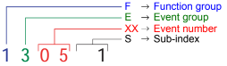
Event numbering display
F E XX S
F Function group; E Event group
XX Event number S Sub index
The first two characters “F, E” refer to the category. The middle
two digits “XX” refer to the event. From these two digits the range:
• 1 to 50 describes standard events (uniform basic events)
which can occur in any function group.
• 51 to 99 describes specific events.
The event is described in further detail through the last characters
“S” (single digit / multi-digit).
This process ensures that a unique number is assigned to each
event. Example:
0 Fault reset or
no fault
1 General fault / additional functions
Example:
Logic error, e.g. both directions selected simultaneously
2 Current
(input interface, device-internal, output interface)
3 Voltage
(input interface, device-internal, output interface)
4 Temperature
5 Hardware
Example: Output transformer short circuit, EEPROM not
responding, …
6 Software
(internal software, application software, data record /
parameters)
Example: EEPROM data error
7 Additional modules
8 CAN monitoring
9 External fault
Example: ISM
-
Contents
-
Table of Contents
-
Troubleshooting
-
Bookmarks
Quick Links
ERE 120
Operating instructions
51222183
02.15
07.12 —
G
ERE 120
ERE C20
Related Manuals for Jungheinrich ERE 120
Summary of Contents for Jungheinrich ERE 120
-
Page 1
ERE 120 07.12 — Operating instructions 51222183 02.15 ERE 120 ERE C20… -
Page 4
Foreword Notes on the operating instructions The present ORIGINAL OPERATING INSTRUCTIONS are designed to provide sufficient instruction for the safe operation of the industrial truck. The information is provided clearly and concisely. The chapters are arranged by letter and the pages are numbered continuously. -
Page 5
Copyright Copyright of these operating instructions remains with JUNGHEINRICH AG. Jungheinrich Aktiengesellschaft Am Stadtrand 35 22047 Hamburg — Germany Tel: +49 (0) 40/6948-0 www.jungheinrich.com… -
Page 6: Table Of Contents
Contents Correct Use and Application ……….. General………………..Correct application………………. Approved application conditions………….. Internal Operation Combined with Brief External or Cold Store Operation (t) ………………….Internal Operation in Cold Stores with Cold Store Equipment (o) ..Proprietor responsibilities ……………. Adding attachments and/or optional equipment ……..Truck Description …………..
-
Page 7
Battery — Servicing, Recharging, Replacement ……. Safety Regulations Governing the Handling of Lead-Acid Batteries ..Battery types……………….. Exposing the battery…………….Charging the battery …………….Charging the battery with a stationary charger……..Charging the battery with an on-board charger (o) …….. Battery removal and installation ………….. -
Page 8
Industrial Truck Maintenance ……….127 Operational Safety and Environmental Protection……..127 Maintenance Safety Regulations…………. 128 Working on the electrical system…………. 129 Consumables and used parts…………..129 Wheels………………… 129 Hydraulic system ………………130 Lift Chains………………..131 Lubricants and Lubrication Schedule …………132 Handling consumables safely ………….. -
Page 10
Appendix JH Traction Battery Operating Instructions These operating instructions apply only to Jungheinrich battery models. If using another brand, refer to the manufacturer’s operating instructions. -
Page 12: A Correct Use And Application
A Correct Use and Application General The truck must be used, operated and serviced in accordance with the present instructions. All other types of use are beyond its scope of application and may result in damage to personnel, the industrial truck or property. Correct application NOTE The maximum load and load distance are indicated on the capacity plate and must…
-
Page 13: Approved Application Conditions
Approved application conditions – Operation in industrial and commercial environments. – Operation only on secure, level surfaces with sufficient capacity. – Do not exceed the permissible surface and spot load limits on the travel routes. – Operation only on routes that are visible and approved by the operating company. –…
-
Page 14: Internal Operation Combined With Brief External Or Cold Store Operation (T)
– Do not charge the battery below +5°C. Internal Operation in Cold Stores with Cold Store Equipment (o) ERE 120 only, not on the ERE C20 In addition to the permissible operating conditions in industrial and commercial environments, the truck remains primarily in cold stores. The truck should only leave the cold store briefly to hand over a load.
-
Page 15: Proprietor Responsibilities
Proprietor responsibilities For the purposes of the present operating instructions the “operating company” is defined as any natural or legal person who either uses the industrial truck himself, or on whose behalf it is used. In special cases (e.g. leasing or renting) the proprietor is considered the person who, in accordance with existing contractual agreements between the owner and user of the industrial truck, is charged with operational duties.
-
Page 16: B Truck Description
B Truck Description Application The industrial truck is a tiller operated electric pallet truck with a folding standing platform and side arms. It is designed for transporting goods on level surfaces. Open bottom pallets or pallets with transverse boards (provided that the boards are outside the perimeter of the load wheels) can be lifted.
-
Page 17: Travel Direction Definition
Travel direction definition The following determinations have been made for travel direction specification: Item Travel direction Left Drive direction Load direction Right…
-
Page 18: Assemblies And Functional Description
Assemblies and Functional Description Assembly Overview Item Component Item Component t Travel switch o CanDis t Tiller t Charge indicator t Key switch 10 t Folding operator platform o CanCode 11 o Folding side restraint o ISM 12 o Mains cable (on-board charger) t Emergency Disconnect (main Support wheel 13 t…
-
Page 19: Functional Description
Functional Description Safety Mechanisms An enclosed, smooth truck perimter with rounded edges ensures safe handling of the truck. The wheels are surrounded by a solid skirt. When released a gas pressure spring pushes the tiller up and activates braking. If the truck touches a person, the red collision safety switch changes the travel direction in pedestrian mode when travelling in drive direction with the platform and the side restraints folded up (o).
-
Page 20
Tiller The driver steers with an ergonomic tiller. All travel and lift operations can be performed sensitively without having to reach. The tiller has a steer angle of 180°. Electrical system The truck has an electronic traction controller. The operating voltage of the truck’s electrical system is 24 volts. -
Page 21: Technical Specifications
The technical specifications comply with the German «Industrial Truck Data Sheet» Guidelines. Technical modifications and additions reserved. Performance data Description ERE 120 ERE C20 Q Rated capacity 2000 Q Rated capacity (support arm lift / mast lift) 2000 / 700…
-
Page 22: Dimensions
Dimensions ERE 120 1053…
-
Page 23
ERE C20 1053 22 4 24 8 b1 1… -
Page 24
Description ERE 120 Tiller height in travel position 1146/1428 Lowered fork height Rated lift b1/b2 Overall width Width across forks 510/540/670 Track width, front 338/368/498 Track width, rear s/e/l Fork dimensions 55/172/1150 Safety clearance Overall length (M/L) 1834/1906 Headlength (M/L) -
Page 25
Description ERE C20 Tiller height in travel position 1146/1428 Lowered fork height Mast lift Support arm lift b1/b2 Overall width Width across forks Track width, front Track width, rear s/e/l Fork dimensions 60/187/1150 Safety clearance Overall length 1850 Length to fork face Ground clearance, centre of wheelbase 1)3)4) Aisle width for pallets 1000×1200… -
Page 26
Aisle widths ERE 120 / ERE C20 (all dimensions in mm) 3)4) 1)3)4) 1)2)3) 2)3)4) Battery compartment L — Headlength l = 754 mm 1000 1756 1269 1000 1517 1954 1150 1906 1419 1200 1667 2154 1200 1956 1469 1200… -
Page 27: Weights
Weights Description ERE 120 Net weight excl. battery (M/L) 440/443 Axle loading, laden 1702/1043 front/rear + battery (L) Axle loading, unladen 155/590 front/rear + battery (L) Weights and axle loads vary depending on truck features. Description ERE C20 Net weight excl. battery…
-
Page 28: En Norms
EN norms Continuous sound pressure level – ERE 120 / ERE C20: 73 dB(A) in accordance with EN 12053 as harmonised with ISO 4871. The continuous sound pressure level is calculated according to standard procedures and takes into account the sound pressure level when driving, lifting and idling.
-
Page 29: Conditions Of Use
Conditions of use Ambient temperature – without cold store equipment: operating at -10°C to 40°C, see «Internal Operation Combined with Brief External or Cold Store Operation (t)» on page 13 – with cold store equipment: operating at -28°C to +25°C, see «Internal Operation in Cold Stores with Cold Store Equipment (o)»…
-
Page 30: Identification Points And Data Plates
Identification Points and Data Plates Warnings and notices such as capacity charts, strap points and data plates must be legible at all times. Replace if necessary. Indication Points ERE 120 Item Component Capacity Qmax Attachment points for lifting by crane…
-
Page 31: Data Plate
ERE C20 2000 Q max Q max Item Component Capacity Qmax Attachment points for lifting by crane Model name Battery data plate Data plate Serial number (etched into the truck chassis) Ergonomic lift capacity plate…
-
Page 32
Data plate The illustration shows the standard version for EU member states. The data plate may differ in other countries. Item Description Item Description Type Year of manufacture Serial number Load centre (mm) Rated capacity (kg) Output Battery voltage (V) Min./max. -
Page 33: Truck Capacity Plate
Truck capacity plate The capacity plate (14) gives the maximum load-bearing capacity (Q) of the truck in kg assuming the load on the load handler is evenly distributed. Capacity plate, ergonomic lift(o) (ERE C20) 2000 Q max Q max Travelling with a raised load prohibited Max.
-
Page 34: C Transport And Commissioning
C Transport and Commissioning Lifting by crane WARNING! All persons involved in loading by crane must be trained Incorrect crane loading procedures due to untrained personnel can cause the truck to fall. There is a risk of injury to personnel and a risk of material damage to the truck. Loading must only be performed by specialist personnel trained for this purpose.
-
Page 35
The truck can now be lifted by crane. -
Page 36: Remove The Transport Lock
Remove the transport lock The transport lock ensures that the truck is braked during transport without the mass of the battery. There is an instruction decal by the front cover for the transport lock (35). This must be removed once the battery has been installed. Remove the transport retainer Requirements –…
-
Page 37: Transport
Transport WARNING! Uncontrolled movement during transport Improper fastening of the truck and mast during transport can result in serious accidents. Loading is only to be carried out by specially trained staff. The specialist personnel must be instructed in the securing of loads on road vehicles and in the use of load- securing equipment.
-
Page 38: Using The Truck For The First Time
Using the Truck for the First Time WARNING! The use of unsuitable energy sources can be hazardous Rectified AC current will damage the assemblies (controllers, sensors, motors etc.) of the electronic system. Unsuitable cable connections (too long, insufficient wire cross-section) to the battery (tow cables) can overheat, setting the truck and battery on fire.
-
Page 40: D Battery — Servicing, Recharging, Replacement
D Battery — Servicing, Recharging, Replacement Safety Regulations Governing the Handling of Lead-Acid Batteries Maintenance personnel Batteries may only be charged, serviced or replaced by trained personnel. These operating instructions and the manufacturer’s instructions concerning batteries and charging stations must be observed when carrying out the work. Fire Protection Do not smoke and avoid naked flames when handling batteries.
-
Page 41
The use of unsuitable batteries that have not been approved for the truck by Jungheinrich, can lead to a deterioration of the braking characteristics of the truck during energy recovery, causing considerable damage to the electric controller and resulting in serious danger to the health and safety of individuals. -
Page 42: Battery Types
The battery weights can be taken from the battery data plate. Batteries with non insulated terminals must be covered with a non slip insulating mat. ERE 120 Battery tray M Battery type Capacity (Ah) Min.
-
Page 43
ERE C20 Battery tray S Battery type Capacity (Ah) Min. weight Max. dimensions (kg) (mm) 24 volt battery 2PzB 200 662X147X686 24 volt battery 2PzVB 170 657X147X686 24 volt battery 2PzVB 142 652X147X560 24 volt battery 2PzB 150 662 x 147 x 592 24 volt battery 2PzB 150 Lib.Silver 144 662 x 147 x 592… -
Page 44: Exposing The Battery
Exposing the battery WARNING! An unsecured truck can cause accidents Parking the truck on an incline or with a raised load handler is dangerous and is strictly prohibited. Park the truck on a level surface. In special cases the truck may need to be secured with wedges.
-
Page 45: Charging The Battery
Charging the battery WARNING! The gases produced during charging can cause explosions The battery gives off a mixture of oxygen and hydrogen (electrolytic gas) during charging. Gassing is a chemical process. This gas mixture is highly explosive and must not be ignited. Switch the charging station and truck off first before connecting/disconnecting the charging cable of the battery charging station to/from the battery connector.
-
Page 46: Charging The Battery With A Stationary Charger
Charging the battery with a stationary charger Charging the battery Requirements – Expose the battery, see «Exposing the battery» on page 43. Procedure • Disconnect battery connector (40) from truck connector. • Connect the battery connector (40) to charging cable (41) stationary charger.
-
Page 47: Charging The Battery With An On-Board Charger (O)
The on-board charger consisting of a battery charger and battery controller must not be opened. If faulty, contact the manufacturer’s customer service department. The charger must only be used for batteries supplied by Jungheinrich or other approved batteries provided it has been adapted by the manufacturer’s customer service department.
-
Page 48
Flashing sequence / charging curve assignment (ELH 2415/2425/2435) Flashing sequence Selected charging curves (characteristics) Wet cell battery: PzS with 100 — 300 Ah Wet cell battery: PzM with 100 — 179 Ah Wet cell battery: PzS with pulse characteristic 200 — 400 Ah Wet cell battery: PzM with pulse characteristic 180 — 400 Ah… -
Page 49
Mains frequency: 50 Hz / 60 Hz The mains connector of the charger (42) is integrated in the battery compartment (the illustration shows the battery compartment of the ERE 120). Charging the battery Requirements – Park the truck securely, see «Parking the truck securely» on page 65. -
Page 50
Completing the battery charge, restoring the truck to operation NOTE If charging has been interrupted, the full battery capacity will not be available Requirements – Battery charging is complete. Procedure • Remove the mains connector from the socket and store it in the battery compartment with the cable. -
Page 51
LED display (43) Green LED (charge status) Charging complete, battery full. (Charge interval, float or compensation charge). Slow flash Charging. Rapid flash Display at beginning of charge or after setting a new characteristic curve. Number of flash pulses corresponds to the characteristic curve set. -
Page 52: Battery Removal And Installation
Battery removal and installation WARNING! Accident risk during battery removal and installation Due to the battery weight and acid there is a risk of trapping or scalding when the battery is removed and installed. Note the «Safety regulations for handling acid batteries» section in this chapter. Wear safety shoes when removing and installing the battery.
-
Page 53: Removing The Battery From The Top
Removing the battery from the top Battery removal Requirements – Park the truck securely, see «Parking the truck securely» on page 65. – Expose the battery, see «Exposing the battery» on page 43. Procedure • Remove the battery panel on trucks with a protective grille (o). •…
-
Page 54: Removing The Battery From The Side
Removing the battery from the side CAUTION! Trapping hazard Trapping hazard when removing and installing the battery. When removing and installing the battery do not put your hands between the battery and the chassis. Battery removal Requirements – Park the truck securely, see «Parking the truck securely»…
-
Page 56: E Operation
E Operation Safety Regulations for the Operation of the Forklift Truck Driver authorisation The truck may only be used by suitably trained personnel, who have demonstrated to the proprietor or his representative that they can drive and handle loads and have been authorised to operate the truck by the proprietor or his representative.
-
Page 57
Hazardous area WARNING! Risk of accidents/injury in the hazardous area of the truck A hazardous area is defined as the area in which people are at risk due to travel or lifting operations of the truck, its load handler or the load. This also includes the area within reach of falling loads or lowering/falling operating equipment. -
Page 58: Displays And Controls
Displays and Controls 52,53,54 7, 9…
-
Page 59
Item Control /Display Function t – Controls the direction of travel as well as Travel switch the travel speed. t – Set to brake zone (B) (see «Brakes» on Tiller page 77): The truck brakes mechanically. – Set to travel zone (F) (see «Brakes» on page 77): The mechanical brake is released and the truck is ready for operation. -
Page 60
Item Control /Display Function t Safety feature Collision safety switch – Pedestrian mode: When applied, the truck travels for approx. 3 seconds in the fork direction. The parking brake then applies. The truck remains switched off until the travel switch is set to neutral. –… -
Page 61: Battery Discharge Monitor
Battery discharge monitor The standard setting for the battery discharge indicator / discharge monitor is based on standard batteries. When using maintenance-free or special batteries, the display and cut-out points of the battery discharge monitor must be set by manufacturer’s service department. If this adjustment is not made, the battery may become damaged due to deep discharge.
-
Page 62: Starting Up The Truck
Starting up the truck Checks and Operations to Be Performed Before Starting Daily Work WARNING! Damage and other truck or attachment (optional equipment) defects can result in accidents. If damage or other truck or attachment (optional equipment) defects are discovered during the following checks, the truck must be taken out of service until it has been repaired.
-
Page 63: Preparing The Truck For Operation
Preparing the truck for operation Switching on the truck Requirements – For checks and operations to be performed before starting daily operation, see «Checks and Operations to Be Performed Before Starting Daily Work» on page 61. Procedure • For rider mode, fold out the operator platform (10) and the side arms (o) (11). •…
-
Page 64
9, 52 54, 56… -
Page 65: Checks And Operations To Be Carried Out When The Truck Is Operational
Checks and operations to be carried out when the truck is operational WARNING! Risk of accident due to damage to or other defects in the truck and optional features If damage or other truck or attachment (optional equipment) defects are discovered during the following checks, the truck must be taken out of service until it has been repaired.
-
Page 66: Parking The Truck Securely
Parking the truck securely WARNING! An unsecured truck can cause accidents Do not leave an unsecured truck. Park the truck securely when leaving it. Exception: If the operator intends to remain in the immediate vicinity and is leaving the truck for only a short while, the applied parking brake is sufficient to hold the truck, see page 78.
-
Page 67
Parking the truck securely Procedure • Park the truck on a level surface. • Fully lower the load handler. • Press the “Lower load handler” button. • Using the tiller, set the drive wheel to «forward travel». • Switch off the truck, to do this: •… -
Page 68: Industrial Truck Operation
Industrial Truck Operation Safety regulations for truck operation Travel routes and work areas Only use lanes and routes specifically designated for truck traffic. Unauthorised third parties must stay away from work areas. Loads must only be stored in places specially designated for this purpose. The truck must only be operated in work areas with sufficient lighting to avoid danger to personnel and materials.
-
Page 69: How To Act In Hazardous Situations
the lift shaft. Persons riding in the lift with the forklift truck must only enter the lift after the truck has come to a rest and must leave the lift before the truck. The driver must ensure that the loading ramp / dock cannot move or come loose during loading / unloading.
-
Page 70: Emergency Disconnect
Emergency Disconnect CAUTION! Applying maximum braking can result in accidents Applying the Emergency Disconnect switch during travel will cause the truck to decelerate to a halt at maximum force. This may cause the load to slide off the load handler. There is a higher risk of accidents and injury. Do not use the Emergency Disconnect switch as a service brake.
-
Page 71
Press the Emergency Disconnect switch Procedure • Press the Emergency Disconnect (8). All electrical functions are deactivated. The truck brakes to a halt. Press the Emergency Disconnect switch on in emergencies. Releasing the Emergency Disconnect switch Procedure • Pull the Emergency Disconnect switch (8) to unlock it. All electrical functions are enabled and the truck is operational again (provided the truck was operational before the Emergency Disconnect was pressed). -
Page 72: Automatic Braking
Automatic braking When the tiller is released, it returns automatically to the upper brake zone (B) and the brakes are applied automatically. WARNING! Risk of collision due to a defective tiller Operating the truck with a defective tiller can lead to collisions with persons or objects. If the tiller returns to the brake position slowly or not at all, the truck must be taken out of service until the cause of this fault is be rectified.
-
Page 73: Travel
Travel WARNING! Collision hazard when operating the truck Collisions with personnel and equipment can result if the truck is operated with open panels. Do not operate the truck unless the panels and covers are closed and properly locked. When travelling through swing doors etc. make sure that the doors do not activate the collision safety button.
-
Page 74
– Travel in pedestrian mode – Travel in rider mode Travelling in pedestrian mode Requirements – Start up the truck, see «Starting up the truck» on page 61 Procedure • Swing in both folding side arms (11) (o). Both side arms must always be folded in, otherwise all functions are deactivated (E-1926). -
Page 75
Travelling is inhibited when the operator platform is vacated and the side arms are not folded out. ERE 120: If the standing platform is occupied and the side arms are not folded out, the truck can only be operated at reduced speed. -
Page 77
4.5.1 Changing direction during travel CAUTION! Danger when changing direction during travel Changing direction during travel causes the truck to decelerate sharply. When the truck changes direction, it can start travelling at high speed in the opposite direction unless the travel switch is released in time. After setting off in the opposite direction, apply the travel switch gently or not at all. -
Page 78: Steering
Steering Procedure • Move the tiller (6) to the left or right. The truck is steered in the required direction. Brakes WARNING! Accident risk The brake pattern of the truck depends largely on the ground conditions. The operator must take into account the travel route conditions when braking. Brake with care to prevent the load from slipping.
-
Page 79
4.7.1 Braking with the service brake Procedure • Move the tiller (6) up or down to one of the brake zones (B). The truck brakes to a halt regeneratively via the service brake. When braking regeneratively, energy is returned to the battery, ensuring a longer service time. -
Page 80: Load Handler Raise/Lower
Load handler raise/lower WARNING! Accident risk when lifting and lowering Other people can be injured in the truck’s hazardous area. The hazardous area is defined as the area in which people are at risk from the movement of the truck including the load handler, etc. This also includes areas which can be reached by falling loads, operating equipment, etc.
-
Page 81
4.8.1 Raising the load handler Requirements – Prepare truck operation, «Preparing the truck for operation» on page 62. 49 50 Procedure • Press the “Raise load handler ” button (50) until you reach the desired lift height. NOTE Risk of material damage to the hydraulic unit When the mechanical end stop of the load has been reached, release the «Raise load handler»… -
Page 82: Lifting, Transporting And Depositing Loads
Lifting, transporting and depositing loads WARNING! Unsecured and incorrectly positioned loads can cause accidents. Before lifting a load unit, the driver must make sure that it has been correctly palletised and does not exceed the truck’s capacity. Instruct other people to move out of the hazardous area of the truck. Stop working with the truck if people do not leave the hazardous area.
-
Page 83
4.9.1 Raising a load Requirements – Load correctly palletised. – Load weight matches the truck’s capacity. – Load handler evenly loaded for heavy loads. Procedure • Drive the truck carefully up to the pallet. • Drive the load handler slowly into the pallet until the pallet is against the back of the load handler (see graphic to the right). -
Page 84
4.9.2 Transporting a load Requirements – Load raised correctly. – ERE 120: Raise the forks completely from the ground to transport correctly (approx. 150 — 200 mm above the ground). – ERE C20: Raise the forks completely from the ground to transport correctly (approx. 150 — 500 mm above the ground ). -
Page 85
4.9.3 Depositing a load CAUTION! Loads must not be set down on transport or escape routes, in front of safety installations or factory equipment that must be accessible at all times. Requirements – Storage location suitable for storing the load. Procedure •… -
Page 86: Ergonomic Lift (O) (Ere C20)
4.10 Ergonomic Lift (o) (ERE C20) For lifting and lowering, the truck is equipped with support arm lift (initial lift) with the maximum lift capacity and mast lift (high lift) with a lower lift capacity, see «Truck capacity plate» on page 32. Raises the load handler When the «Load handler lift»…
-
Page 87
4.10.1 Use as a Lift Work Table The load handler can remain in a raised position to be used as a lift work table when the truck is switched off, provided the operator is close to the truck. Immediate vicinity of the truck is when the operator is able to respond to malfunctions or attempts to use the truck by unauthorised persons immediately. -
Page 89: Troubleshooting
Troubleshooting This chapter enables the operator to localize and rectify basic faults or the results of incorrect operation himself. When trying to locate a fault, proceed in the order shown in the remedy table. If, after carrying out the following remedial action, the truck cannot be restored to operation or if a fault in the electronics system is displayed with a corresponding error code, contact the manufacturer’s service department.
-
Page 90: Truck Does Not Start
Truck does not start Possible cause Corrective measures Battery connector not plugged in. Check the battery connector and connect if necessary. Emergency disconnect switch pressed Unlock the emergency disconnect switch Key switch set to O Set the key switch to “I” Battery charge too low Check battery charge, charge the battery if necessary…
-
Page 91: Load Cannot Be Lifted
Load cannot be lifted Possible cause Corrective measures Truck not operational Carry out all measures listed under “Truck does not start” Hydraulic oil level too low Check the hydraulic oil level, see page 142 Battery discharge monitor has switched Charge the battery, see page 44 Faulty fuse Check the fuses, see page 143 Excessive load…
-
Page 92: Operating The Truck Without Its Own Drive System
Operating the truck without its own drive system With the right optional equipment (o) it is possible to switch the truck to emergency operation via the GF60 service key: The brakes are released electrically and the truck can move without its own drive system, see «Emergency operation with service key GF60″…
-
Page 93
WARNING! Only return the truck to service when you have identified and rectified the fault. -
Page 94: Optional Equipment
Optional equipment Emergency operation with service key GF60 WARNING! The truck can move accidentally when the brake is released The GF60 service key must not remain on the truck during normal operation. The service key should only be used by an authorised person (e.g. warehouse manager).
-
Page 95
Parking the truck securely Procedure • Set the key switch to the “0” position and remove the key. When you switch back from level 2 to level 1 the bar returns to its original position. The brake is now activated again. GF 30 The GF30 key without a bar is designed for normal truck operation. -
Page 96: Cancode Keypad (O)
CanCode Keypad (o) 7.2.1 Code lock The code lock allows a user or group of users to assign an individual user code. Travel programs can also be assigned to the individual user codes. The user code is configured with a master code and is described in the following sections in this chapter.
-
Page 97
The keypad consists of 10 digit keys, a Set key (61) and a o key (63). Digit keys The digit keys are used to enter the user or master code and select the travel program. The green LEDs of the digit keys 1, 2 and 3 (58, 59, 60) show the travel program setting. -
Page 98
7.2.2 Preparing the truck for operation with the keypad (CanCode) Preparing the truck for operation by entering a valid operator code Procedure • Pull the Emergency Disconnect to unlock it, see «Emergency Disconnect» on page 69. The LED (62) lights up red. •… -
Page 99
7.2.4 Changing the master code To change the length of the master code you must follow the procedure in «Choose length of the new master code (4-6 digit) and add user codes», see «Choose length of the new master code (4-6 digit) and add user codes» on page 107. If there are still user codes stored in the code lock, the master code to be changed must be the same length as the saved user codes. -
Page 100
Error displays changing the master code For the following events the LED (62) flashes red: Cause Remedy – New master code is already – Switch off the truck, see «Switching off the truck occupied by a user code with the keypad (CanCode)» on page 97. –… -
Page 101
7.2.5 Add operator code Requirements – To prepare the truck for operation, see «Preparing the truck for operation with the keypad (CanCode)» on page 97. Procedure • Press the O key (63). • Enter the valid master code with the digit keys. When you enter the valid master code the LED (62) flashes green. -
Page 102
Error displays adding a user code For the following events the LED (62) flashes red: Cause Remedy – The user code entered is not – Switch off the truck, see «Switching off the truck the same length as the with the keypad (CanCode)» on page 97. master code –… -
Page 103
7.2.6 Change operator code Requirements – To prepare the truck for operation, see «Preparing the truck for operation with the keypad (CanCode)» on page 97. Procedure • Press the O key (63). • Enter the valid master code with the digit keys. When you enter the valid master code the LED (62) flashes green. -
Page 104
Error displays changing a user code For the following events the LED (62) flashes red: Cause Remedy – The user code entered is not – Switch off the truck, see «Switching off the truck the same length as the with the keypad (CanCode)» on page 97. master code –… -
Page 105
7.2.7 Delete individual user codes Requirements – To prepare the truck for operation, see «Preparing the truck for operation with the keypad (CanCode)» on page 97. Procedure • Press the O key (63). • Enter the valid master code with the digit keys. When you enter the valid master code the LED (62) flashes green. -
Page 106
Error displays deleting individual user codes For the following events the LED (62) flashes red: Cause Remedy – The user code entered is not – Switch off the truck, see «Switching off the truck the same length as the with the keypad (CanCode)» on page 97. master code –… -
Page 107
7.2.8 Delete all user codes, Requirements – To prepare the truck for operation, see «Preparing truck operation with keypad (CanCode)» on page 97. Procedure • Press the O key (63). • Enter the valid master code with the digit keys. When you enter the valid master code the LED (62) flashes green. -
Page 108
7.2.9 Choose length of the new master code (4-6 digit) and add user codes The master code is factory set to a four-digit entry: If necessary, the four-digit master code can be changed to a five or six-digit entry. Before the master code length can be changed, all user codes must be deleted. -
Page 109
7.2.10 Setting the automatic truck cutout (timeframe) Requirements – To prepare the truck for operation, see «Preparing the truck for operation with the keypad (CanCode)» on page 97. Procedure • Press the O key (63). • Enter the valid master code with the digit keys. When you enter the correct master code the LED (62) flashes green. -
Page 110
Cause Remedy – Cutout time entered is out of – Switch off the truck, see «Switching off the truck range with the keypad (CanCode)» on page 97. – Enter the time again while making sure it is within range. Fixed cutout time (o) An automatic truck cutout is factory-set. -
Page 111
7.2.11 Assigning the travel program The travel programs are fixed to the user code and can be released or blocked with a configuration code. The configuration code can also be used to assign a starting travel program to each user code. The starting travel program is the travel program that is activated when the truck is switched on and is displayed by the (58,59,60) LEDs. -
Page 112
Specifying a configuration code: Setting Description – Travel program 1 is blocked for the user code selected 1st digit – Travel program 1 is enabled for the user code selected – Travel program 2 is blocked for the user code selected 2nd digit –… -
Page 113
Adapting the travel program configuration to the user code Procedure • Press the O key (63). • Enter the valid master code with the digit keys. When you enter the valid master code the green LED (62) flashes green. • Enter the parameters 0-2-4 with the digit keys. •… -
Page 114
Error displays configuring the travel programs For the following events the LED (62) flashes red: Cause Remedy – Blocked travel program – Switch off the truck, see «Switching off the truck defined as start travel with the keypad (CanCode)» on page 97. program –… -
Page 115: Setting The Truck Parameters With Cancode
Setting the truck parameters with CanCode CAUTION! Faulty entry Without CanDis only CanCode internal parameters can be changed. Traction controller parameters can only be changed with CanDis, without CanDis the settings must be performed by the manufacturer’s service department. CAUTION! Altering settings for the travel and hydraulic functions can result in accidents Increasing the settings for travel and hydraulic functions can result in accidents.
-
Page 116
To continue setting, confirm with the Set key (61) again. Saving travel parameters Requirements – Enter all parameters. Procedure • Run «SaveParameters» by pressing 1-2-3-Set. • Confirm with the O key (63). -
Page 117: Parameters
0256 Acceleration 0 — 9 Platform folded (0.13 — 1.88 m/s 0.67 m/s out, side arms folded out 0264 ERE 120: Maximum speed in drive 0 — 9 direction using travel (4.5 — 9.0 km/h) 6.0 km/h switch ERE C20:…
-
Page 118
0272 Acceleration 0 — 9 Platform folded (0.13 — 1.88 m/s 1.08 m/s out, side arms folded out 0280 ERE 120: Maximum speed in drive 0 — 9 direction using travel (4.5 — 9.0 km/h) 8.5 km/h switch ERE C20:… -
Page 119
0288 Acceleration 0 — 9 Platform folded (0.13 — 1.88 m/s 1.62 m/s out, side arms folded out 0296 ERE 120: Maximum speed in drive 0 — 9 direction using travel (4.5 — 9.0 km/h) 8.5 km/h switch ERE C20:… -
Page 120
Battery parameters Function Range Standard Comments setting 1377 Battery type 0 — 5 0 = Normal (wet) (normal / high 1 = High performance performance / dry) (wet) 2 = Dry (maintenance-free) 3 = US «Flat Plate» type 4 = US «Pallet Pro» type 5 = US «Tubular Plate»… -
Page 121
Function Range Standard Comments setting 1388 ELH charger 0 — 6 characteristic curve No charging function 1 = PzS wet cell batteries 100 — 300 Ah and PzM batteries from 0 — 179 Ah 2 = PzS wet cell batteries with pulse characteristics 200 — 400 Ah and PzM batteries from 180 -… -
Page 122: Setting The Battery Parameters With Cancode
Setting the Battery Parameters with CanCode WARNING! Altering parameters cause accidents Altering settings cause accidents. This requires greater attention on the part of the operator The following example shows the parameter setting for the battery type (parameter 1377) to «dry — maintenance-free».
-
Page 123
Testing an altered parameter Requirements – The parameter is now saved. Procedure • Press the O key (63). • Enter the master code. • Enter the four-digit parameter number «1377» and confirm with the Set key. • Enter sub index «2» and confirm with the Set key. The parameter with subindex are displayed alternately with the current reading. -
Page 124: Set Elh 2415 / 2425 / 2435 Charger Characteristics With Cancode
Set ELH 2415 / 2425 / 2435 Charger Characteristics with CanCode Parameter setting example The following example shows the charging characteristics parameter setting for a maintenance-free battery with 201 — 300 Ah. Requirements – CanCode and CanDis are available. Procedure •…
-
Page 125
The parameter with sub index are displayed alternately with the current reading. E.g. (1388-2<->0000-5) corresponds to the charging characteristics for the maintenance-free battery with 201 — 300 Ah. • Press the O key. The parameter has now been checked. -
Page 126: Candis Display Instrument (O)
CanDis Display Instrument (o) The instrument indicates: Battery charge display (on board charger only) LED bars for battery charge status «Warning» symbol (yellow), Battery charge recommended «Stop» symbol (red); lift cutout, Battery charge essential No symbol when battery type set to normal or enhanced performance wet cell battery «T»…
-
Page 127: Ism Access Module (O)
7.7.1 Discharge monitor function The discharge limit has been reached when the «Stop» symbol (67) lights up. When the discharge monitor function is activated lifting operations are disabled. Travel and lowering are still possible. Lifting is only enabled again when the battery is 70% charged.
-
Page 128: F Industrial Truck Maintenance
F Industrial Truck Maintenance Operational Safety and Environmental Protection The checks and servicing operations contained in this chapter must be performed in accordance with the maintenance checklist service intervals. WARNING! Risk of accidents and component damage Any modification to the truck, in particular the safety mechanisms, is prohibited. Exception: Operating companies should only make changes or have changes made to powered industrial trucks if the manufacturer is no longer operating in the field and there is no successor to the business;…
-
Page 129: Maintenance Safety Regulations
Maintenance Safety Regulations Maintenance and repair personnel The manufacturer has a service department specially trained for these tasks. A maintenance contract with the manufacturer will ensure trouble-free operation. Truck maintenance and repair work must only be carried out by specially trained personnel.
-
Page 130: Working On The Electrical System
Working on the electrical system WARNING! Electrical current can cause accidents Make sure the electrical system is voltage-free before starting work on it. The capacitors in the controller must be completely discharged. The capacitors are completely discharged after approximately 10 minutes. Before starting maintenance on the electrical system: Only suitably trained electricians may operate on the truck’s electrical system.
-
Page 131: Hydraulic System
Hydraulic system WARNING! Leaky hydraulic systems can result in accidents Hydraulic oil can escape from leaky and faulty hydraulic systems. Report any defects immediately to your supervisor. Mark defective truck and take out of service. Do not return the industrial truck to service until you have identified and rectified the fault.
-
Page 132: Lift Chains
Lift Chains WARNING! Non-lubricated and incorrectly cleaned lift chains can cause accidents Lift chains are safety-critical parts. They must not contain any serious contamination. Lift chains and pivot pins must always be clean and well lubricated. Lift chains should only be cleaned with paraffin derivatives e.g. petroleum or diesel fuels.
-
Page 133: Lubricants And Lubrication Schedule
Lubricants and Lubrication Schedule Handling consumables safely Handling consumables Consumables must always be handled correctly. Follow the manufacturer’s instructions. WARNING! Improper handling is hazardous to health, life and the environment Consumables can be flammable. Keep consumables away from hot components and naked flames. Always keep consumables in prescribed containers.
-
Page 134
WARNING! Improper handling of oils can be hazardous Oils (chain spray / hydraulic oil) are flammable and poisonous. Dispose of used oils in accordance with regulations. Store used oil safely until it can be disposed of in accordance with regulations. Do not spill oil. -
Page 135: Lubrication Schedule
Lubrication Schedule 0,7l 0,55 l g Contact surfaces Cold Store Application s Grease nipple b Transmission oil filler neck a Transmission oil drain plug Transmission oil overflow and dipstick Hydraulic oil filler neck 1 Compound ratio for cold store usage 1:1…
-
Page 136: Consumables
The Jungheinrich hydraulic oil can only be obtained from the Jungheinrich service department. The use of named alternative hydraulic oils is not prohibited but may lead to a decline in functionality. The Jungheinrich hydraulic oil may be mixed with one of the named alternative hydraulic oils.
-
Page 137: Maintenance And Repairs
Maintenance and repairs Prepare the truck for maintenance and repairs All necessary safety measures must be taken to avoid accidents when carrying out maintenance and repairs. The following preparations must be made: Procedure • Park the truck securely, see «Parking the truck securely» on page 65. •…
-
Page 138: Front Cover Disassembly
Front cover disassembly Front cover disassembly Procedure • Fold down the operator platform (10). • Release the compartment panel latch using a spanner (width
 and expose the panel latch. • Release the panel latch (71) using a spanner (width 8). •…
 -
Page 139: Lifting And Jacking Up The Truck Safely
Lifting and jacking up the truck safely WARNING! Lifting and jacking up the truck safely In order to raise the truck, the lifting gear must only be secured to the points specially provided for this purpose. You may only work under a raised load handler if it has been secured with a sufficiently strong chain or the fastening bolt.
-
Page 140: Cleaning
Cleaning 4.4.1 Cleaning the truck CAUTION! Fire hazard Do not use flammable liquids to clean the industrial truck. Disconnect the battery before starting cleaning work. Carry out all necessary safety measures to prevent sparking before cleaning (e.g. by short-circuiting). CAUTION! Risk of component damage when cleaning the truck Cleaning with a pressure washer can result in malfunctions due to humidity.
-
Page 141
Cleaning the truck Requirements – Prepare the truck for maintenance and repairs (see «Prepare the truck for maintenance and repairs» on page 136). Tools and Material Required – Water-based solvents – Sponge or cloth Procedure • Clean the surface of the truck with water-based solvents and water. Use a sponge or cloth to clean. -
Page 142
4.4.2 Cleaning the electrical system assemblies CAUTION! Risk of electrical system damage Cleaning the assemblies (controllers, sensors, motors etc.) of the electronic system with water can damage the electrical system. Do not clean the electrical system with water. Clean the electrical system with weak suction or compressed air (use a compressor with a water trap) and not a conductive, anti-static brush. -
Page 143: Replacing The Drive Wheel
Replacing the drive wheel The drive wheel must only be replaced by authorised service personnel. Checking the hydraulic oil level Check oil level Requirements – Lower the load handler. – Prepare the truck for maintenance and repairs, see «Prepare the truck for maintenance and repairs»…
-
Page 144: Checking Electrical Fuses
Checking electrical fuses Check fuses Requirements – Truck prepared for maintenance and repairs, see «Prepare the truck for maintenance and repairs» on page 136. – Front cover removed, see «Front cover disassembly» on page 137. Procedure • Check the fuse ratings against the table and replace if necessary. The fuses are now checked.
-
Page 145
Item Component To protect Rating (A) 9F22 Control fuse 2 (after main contactor) Display / battery hour meter Control fuse 1 (before main contactor) Spare Spare for option Drive / lift motor main fuse… -
Page 146: Restoring The Truck To Service After Maintenance And Repairs
Restoring the truck to service after maintenance and repairs Procedure • Thoroughly clean the truck, see «Cleaning the truck» on page 139. • Lubricate the truck according to the lubrication schedule, see «Lubrication Schedule» on page 134. • Clean the battery, grease the terminals and connect the battery. •…
-
Page 147: Decommissioning The Industrial Truck
Decommissioning the Industrial Truck If the truck is to be out of service for more than a month, it must be stored in a frost- free and dry room. All necessary measures must be taken before, during and after decommissioning as described hereafter. When the truck is out of service it must be jacked up so that all the wheels are clear of the ground.
-
Page 148: Restoring The Truck To Service After Decommissioning
Restoring the truck to service after decommissioning Procedure • Thoroughly clean the truck, see «Cleaning» on page 139. • Lubricate the truck according to the lubrication schedule, see «Lubrication Schedule» on page 134. • Clean the battery, grease the terminals and connect the battery. •…
-
Page 149: Safety Tests To Be Performed At Intervals And After Unusual Incidents
Safety tests to be performed at intervals and after unusual incidents The truck must be inspected at least annually (refer to national regulations) or after any unusual event by a qualified inspector. The manufacturer offers a safety inspection service which is performed by personnel specifically trained for this purpose.
-
Page 150: Servicing And Inspection
Servicing and Inspection WARNING! Lack of maintenance can result in accidents Failure to perform regular servicing can lead to truck failure and poses a potential hazard to personnel and equipment. Thorough and expert servicing is one of the most important requirements for the safe operation of the industrial truck.
-
Page 151: Maintenance Checklist
Maintenance checklist 10.1 Operating Company 10.1.1 Standard Equipment Braking W A B C Test brakes. Electrical W A B C Test warning and safety devices in accordance with operating instructions. Test emergency disconnect switch. Power supply W A B C Check battery cable connections are secure, check for dirt and grease terminals if necessary.
-
Page 152
On-board charger 35A Battery charger W A B C Check mains connector and mains cable. Standard on-board charger Battery charger W A B C Check mains connector and mains cable. -
Page 153: 10.2 Customer Service
10.2 Customer Service 10.2.1 Standard Equipment Braking W A B C Test brakes. Check the air gap of the magnetic brake. Electrical W A B C Check cables and motor mounting are secure. Test warning and safety devices in accordance with operating instructions.
-
Page 154
Chassis and Superstructure W A B C Check chassis and screw connections for damage. Check doors and/or covers. Check labels are legible, complete and make sense. Test the operator platform and check for damage. Check operator mat and steps are non-slip and damage-free. Hydraulic Operations W A B C Test «hydraulic»… -
Page 155
Automatic crawl speed Travel W A B C Check that sensors/switches are secured, not damaged, clean and operational. Battery refill system Power supply W A B C Test battery refill system and check for leaks. On-board charger 35A Battery charger W A B C Check mains connector and mains cable. -
Page 156
Ergonomic lift Hydraulic Operations W A B C Test the lift sensors in the mast and initial lift and check for damage. Check settings and wear levels of slide pieces and stops and adjust the slide pieces if necessary. Check load chain setting and tension if necessary. Check lateral clearance of the mast connections and the fork carriage. -
Page 158
A Traction Battery Appendix Contents Traction Battery Appendix…………Correct Use and Application…………..Data plate ………………..Safety Instructions, Warning Indications and other Notes ……. Lead acid batteries with armour plated cells and liquid electrolyte..Description………………..Operation………………..Servicing lead-acid batteries with armour plated cells……PzV and PzV-BS lead-acid batteries with sealed armour plated cells.. -
Page 159: Correct Use And Application
Correct Use and Application Failure to observe the operating instructions, carrying out repairs with non-original spare parts, tampering with the battery or using electrolyte additives will invalidate the warranty. Observe the instructions for maintaining the safety rating during operation for batteries in accordance with Ex I and Ex II (see relevant certification).
-
Page 160: Safety Instructions, Warning Indications And Other Notes
Safety Instructions, Warning Indications and other Notes Used batteries must be treated as hazardous waste. These batteries are marked with the recycling symbol and the sign showing a crossed-out rubbish bin, and should not be disposed of with ordinary household waste. waste.
-
Page 161: Lead Acid Batteries With Armour Plated Cells And Liquid Electrolyte
Lead acid batteries with armour plated cells and liquid electrolyte Description Jungheinrich traction batteries are lead acid batteries with armour plated cells and liquid electrolyte. The names of the traction batteries are PzS, PzB, PzS Lib and PzM. Electrolyte The rated density of the electrolyte assumes a temperature of 30°C and the rated electrolyte level is fully charged.
-
Page 162: Operation
Operation 4.2.1 Commissioning unfilled batteries The operations required must be carried out by the manufacturer’s customer service department or a customer service organisation authorised by the manufacturer. 4.2.2 Commissioning filled and charged batteries Checks and operations to be performed before starting daily work Procedure •…
-
Page 163
4.2.4 Charging the battery WARNING! The gases produced during charging can cause explosions The battery gives off a mixture of oxygen and hydrogen (electrolytic gas) during charging. Gassing is a chemical process. This gas mixture is highly explosive and must not be ignited. Always disconnect the charger and truck before connecting or disconnecting the charger and battery. -
Page 164
The electrolyte temperature rises by approx. 10 K during charging. Charging should therefore only begin when the electrolyte temperature is below 45°C. The electrolyte temperature of batteries must be at least +10°C before charging. Otherwise the battery will not charge correctly. Below 10°C the battery is insufficiently charged with standard charging systems. -
Page 165: Servicing Lead-Acid Batteries With Armour Plated Cells
Servicing lead-acid batteries with armour plated cells Water quality The quality of the water used to fill up electrolyte must correspond to purified or distilled water. Purified water can be produced through distillation or ion exchangers and is then suitable for the production of electrolyte. 4.3.1 Daily –…
-
Page 166: Pzv And Pzv-Bs Lead-Acid Batteries With Sealed Armour Plated Cells
PzV and PzV-BS lead-acid batteries with sealed armour plated cells Description PzV batteries are sealed batteries with fixed electrolytes, to which no water can be added over the entire lifespan of the battery. Relief valves are used as plugs which are destroyed when opened.
-
Page 167: Operation
Operation 5.2.1 Commissioning Checks and operations to be performed before starting daily work Procedure • Make sure the battery is in physically good condition. • Make sure the terminals are correct (positive to positive and negative to negative) and check that contacts on the battery terminal conducting system are secure. •…
-
Page 168
NOTE Charging the battery incorrectly can result in material damage. Incorrect battery charging can result in overloading of the electric wires and contacts, hazardous gas formation and electrolyte leakage from the cells. Always charge the battery with DC current. All DIN 41773 charging procedures are permitted in the format approved by the manufacturer. -
Page 169
Charging the battery Requirements – Electrolyte temperature between +15°C and 35°C Procedure • Open or take off the tray lid or covers from the battery compartment. • Connect the battery to the switched off charger, ensuring the terminals are connect (positive to positive and negative to negative). -
Page 170: Servicing Pzv And Pzv-Bs Lead-Acid Batteries With Sealed Armour Plated Cells
Servicing PzV and PzV-BS lead-acid batteries with sealed armour plated cells Do not add water! 5.3.1 Daily – Charge the battery after each discharge. 5.3.2 Weekly – Visually inspect for dirt and physical damage. 5.3.3 Every three months – Measure and record the overall voltage. –…
-
Page 171: Aquamatik Water Replenishment System
Aquamatik water replenishment system Water replenishment system design > 3 m Water container Tap connection with ball cock Flow indicator Shut-off cock Locking coupling Battery lock connector…
-
Page 172: Functional Description
Functional Description The Aquamatik water replenishment system is used to adjust the rated electrolyte level automatically on traction batteries for industrial trucks. The battery cells are interconnected through hoses and are attached to the water supply (e.g. water container) through a plug connection. When the shut-off cock is opened all the cells are filled with water.
-
Page 173: Filling Time
Filling time The filling time for a battery depends on the electrolyte level, the ambient temperature and the filling pressure. Filling ends automatically. The water supply line must be disconnected from the battery when the water has been filled. Water quality The quality of the water used to fill up electrolyte must correspond to purified or distilled water.
-
Page 174: Cleaning Measures
Cleaning measures The plug systems must only be cleaned with purified water in accordance with DIN 43530-4. No parts of the plugs must come into contact with solvent-based materials or soap. 6.10 Service mobile vehicle Mobile water filling vehicle with pump and filling gun to fill individual cells. The immersion pump in the container generates the necessary filling pressure.
-
Page 175: Electrolyte Circulation
Electrolyte circulation Functional Description Electrolyte circulation ensures the supply of air during charging to mix the electrolyte, thereby preventing any acid layer, shortening the charge time (charge factor approx. 1.07) and reducing the formation of gas during charging. The charger must be suitable for the battery and electrolyte circulation.
-
Page 176
NOTE If an installed electrolyte circulation system is seldom used or not used at all, or if the battery is subjected to severe temperature fluctuations, the electrolyte may flow back into the hose system. Attach a separate coupling system to the air inlet line, such as: locking coupling on the battery side and through-coupling on the air supply side. -
Page 177: Cleaning Batteries
Cleaning batteries Batteries and trays must be cleaned in order to – maintain cell insulation and protect cells from ground or external conductive parts. – Avoid damage from corrosion and stray currents. – Avoid excessive and varying automatic discharge of the individual cells or block batteries due to stray currents.
-
Page 178
Cleaning the battery with a high pressure cleaner Requirements – Cell connectors tight, plugged in securely – Cell plugs closed Procedure • Follow the high pressure cleaner’s user instructions. • Do not use any cleaning additives. • Observe the permissible cleaning device temperature setting of 140°C. This generally ensures that the temperature does not exceed 60°C at a distance of 30cm behind the outlet nozzle. -
Page 179: Storing The Battery
Storing the battery NOTE The battery should not be stored for longer than 3 months without charging as otherwise it will no longer be functional. If the battery is to be taken out of service for a long period, it should be stored fully charged in a dry room protected from frost.
 and expose the panel latch. • Release the panel latch (71) using a spanner (width 8). •…
-
Contents
-
Table of Contents
-
Troubleshooting
-
Bookmarks
Quick Links
ERE 120
Operating instructions
51222183
02.15
07.12 —
G
ERE 120
ERE C20
Related Manuals for Jungheinrich ERE 120
Summary of Contents for Jungheinrich ERE 120
-
Page 1
ERE 120 07.12 — Operating instructions 51222183 02.15 ERE 120 ERE C20… -
Page 4
Foreword Notes on the operating instructions The present ORIGINAL OPERATING INSTRUCTIONS are designed to provide sufficient instruction for the safe operation of the industrial truck. The information is provided clearly and concisely. The chapters are arranged by letter and the pages are numbered continuously. -
Page 5
Copyright Copyright of these operating instructions remains with JUNGHEINRICH AG. Jungheinrich Aktiengesellschaft Am Stadtrand 35 22047 Hamburg — Germany Tel: +49 (0) 40/6948-0 www.jungheinrich.com… -
Page 6: Table Of Contents
Contents Correct Use and Application ……….. General………………..Correct application………………. Approved application conditions………….. Internal Operation Combined with Brief External or Cold Store Operation (t) ………………….Internal Operation in Cold Stores with Cold Store Equipment (o) ..Proprietor responsibilities ……………. Adding attachments and/or optional equipment ……..Truck Description …………..
-
Page 7
Battery — Servicing, Recharging, Replacement ……. Safety Regulations Governing the Handling of Lead-Acid Batteries ..Battery types……………….. Exposing the battery…………….Charging the battery …………….Charging the battery with a stationary charger……..Charging the battery with an on-board charger (o) …….. Battery removal and installation ………….. -
Page 8
Industrial Truck Maintenance ……….127 Operational Safety and Environmental Protection……..127 Maintenance Safety Regulations…………. 128 Working on the electrical system…………. 129 Consumables and used parts…………..129 Wheels………………… 129 Hydraulic system ………………130 Lift Chains………………..131 Lubricants and Lubrication Schedule …………132 Handling consumables safely ………….. -
Page 10
Appendix JH Traction Battery Operating Instructions These operating instructions apply only to Jungheinrich battery models. If using another brand, refer to the manufacturer’s operating instructions. -
Page 12: A Correct Use And Application
A Correct Use and Application General The truck must be used, operated and serviced in accordance with the present instructions. All other types of use are beyond its scope of application and may result in damage to personnel, the industrial truck or property. Correct application NOTE The maximum load and load distance are indicated on the capacity plate and must…
-
Page 13: Approved Application Conditions
Approved application conditions – Operation in industrial and commercial environments. – Operation only on secure, level surfaces with sufficient capacity. – Do not exceed the permissible surface and spot load limits on the travel routes. – Operation only on routes that are visible and approved by the operating company. –…
-
Page 14: Internal Operation Combined With Brief External Or Cold Store Operation (T)
– Do not charge the battery below +5°C. Internal Operation in Cold Stores with Cold Store Equipment (o) ERE 120 only, not on the ERE C20 In addition to the permissible operating conditions in industrial and commercial environments, the truck remains primarily in cold stores. The truck should only leave the cold store briefly to hand over a load.
-
Page 15: Proprietor Responsibilities
Proprietor responsibilities For the purposes of the present operating instructions the “operating company” is defined as any natural or legal person who either uses the industrial truck himself, or on whose behalf it is used. In special cases (e.g. leasing or renting) the proprietor is considered the person who, in accordance with existing contractual agreements between the owner and user of the industrial truck, is charged with operational duties.
-
Page 16: B Truck Description
B Truck Description Application The industrial truck is a tiller operated electric pallet truck with a folding standing platform and side arms. It is designed for transporting goods on level surfaces. Open bottom pallets or pallets with transverse boards (provided that the boards are outside the perimeter of the load wheels) can be lifted.
-
Page 17: Travel Direction Definition
Travel direction definition The following determinations have been made for travel direction specification: Item Travel direction Left Drive direction Load direction Right…
-
Page 18: Assemblies And Functional Description
Assemblies and Functional Description Assembly Overview Item Component Item Component t Travel switch o CanDis t Tiller t Charge indicator t Key switch 10 t Folding operator platform o CanCode 11 o Folding side restraint o ISM 12 o Mains cable (on-board charger) t Emergency Disconnect (main Support wheel 13 t…
-
Page 19: Functional Description
Functional Description Safety Mechanisms An enclosed, smooth truck perimter with rounded edges ensures safe handling of the truck. The wheels are surrounded by a solid skirt. When released a gas pressure spring pushes the tiller up and activates braking. If the truck touches a person, the red collision safety switch changes the travel direction in pedestrian mode when travelling in drive direction with the platform and the side restraints folded up (o).
-
Page 20
Tiller The driver steers with an ergonomic tiller. All travel and lift operations can be performed sensitively without having to reach. The tiller has a steer angle of 180°. Electrical system The truck has an electronic traction controller. The operating voltage of the truck’s electrical system is 24 volts. -
Page 21: Technical Specifications
The technical specifications comply with the German «Industrial Truck Data Sheet» Guidelines. Technical modifications and additions reserved. Performance data Description ERE 120 ERE C20 Q Rated capacity 2000 Q Rated capacity (support arm lift / mast lift) 2000 / 700…
-
Page 22: Dimensions
Dimensions ERE 120 1053…
-
Page 23
ERE C20 1053 22 4 24 8 b1 1… -
Page 24
Description ERE 120 Tiller height in travel position 1146/1428 Lowered fork height Rated lift b1/b2 Overall width Width across forks 510/540/670 Track width, front 338/368/498 Track width, rear s/e/l Fork dimensions 55/172/1150 Safety clearance Overall length (M/L) 1834/1906 Headlength (M/L) -
Page 25
Description ERE C20 Tiller height in travel position 1146/1428 Lowered fork height Mast lift Support arm lift b1/b2 Overall width Width across forks Track width, front Track width, rear s/e/l Fork dimensions 60/187/1150 Safety clearance Overall length 1850 Length to fork face Ground clearance, centre of wheelbase 1)3)4) Aisle width for pallets 1000×1200… -
Page 26
Aisle widths ERE 120 / ERE C20 (all dimensions in mm) 3)4) 1)3)4) 1)2)3) 2)3)4) Battery compartment L — Headlength l = 754 mm 1000 1756 1269 1000 1517 1954 1150 1906 1419 1200 1667 2154 1200 1956 1469 1200… -
Page 27: Weights
Weights Description ERE 120 Net weight excl. battery (M/L) 440/443 Axle loading, laden 1702/1043 front/rear + battery (L) Axle loading, unladen 155/590 front/rear + battery (L) Weights and axle loads vary depending on truck features. Description ERE C20 Net weight excl. battery…
-
Page 28: En Norms
EN norms Continuous sound pressure level – ERE 120 / ERE C20: 73 dB(A) in accordance with EN 12053 as harmonised with ISO 4871. The continuous sound pressure level is calculated according to standard procedures and takes into account the sound pressure level when driving, lifting and idling.
-
Page 29: Conditions Of Use
Conditions of use Ambient temperature – without cold store equipment: operating at -10°C to 40°C, see «Internal Operation Combined with Brief External or Cold Store Operation (t)» on page 13 – with cold store equipment: operating at -28°C to +25°C, see «Internal Operation in Cold Stores with Cold Store Equipment (o)»…
-
Page 30: Identification Points And Data Plates
Identification Points and Data Plates Warnings and notices such as capacity charts, strap points and data plates must be legible at all times. Replace if necessary. Indication Points ERE 120 Item Component Capacity Qmax Attachment points for lifting by crane…
-
Page 31: Data Plate
ERE C20 2000 Q max Q max Item Component Capacity Qmax Attachment points for lifting by crane Model name Battery data plate Data plate Serial number (etched into the truck chassis) Ergonomic lift capacity plate…
-
Page 32
Data plate The illustration shows the standard version for EU member states. The data plate may differ in other countries. Item Description Item Description Type Year of manufacture Serial number Load centre (mm) Rated capacity (kg) Output Battery voltage (V) Min./max. -
Page 33: Truck Capacity Plate
Truck capacity plate The capacity plate (14) gives the maximum load-bearing capacity (Q) of the truck in kg assuming the load on the load handler is evenly distributed. Capacity plate, ergonomic lift(o) (ERE C20) 2000 Q max Q max Travelling with a raised load prohibited Max.
-
Page 34: C Transport And Commissioning
C Transport and Commissioning Lifting by crane WARNING! All persons involved in loading by crane must be trained Incorrect crane loading procedures due to untrained personnel can cause the truck to fall. There is a risk of injury to personnel and a risk of material damage to the truck. Loading must only be performed by specialist personnel trained for this purpose.
-
Page 35
The truck can now be lifted by crane. -
Page 36: Remove The Transport Lock
Remove the transport lock The transport lock ensures that the truck is braked during transport without the mass of the battery. There is an instruction decal by the front cover for the transport lock (35). This must be removed once the battery has been installed. Remove the transport retainer Requirements –…
-
Page 37: Transport
Transport WARNING! Uncontrolled movement during transport Improper fastening of the truck and mast during transport can result in serious accidents. Loading is only to be carried out by specially trained staff. The specialist personnel must be instructed in the securing of loads on road vehicles and in the use of load- securing equipment.
-
Page 38: Using The Truck For The First Time
Using the Truck for the First Time WARNING! The use of unsuitable energy sources can be hazardous Rectified AC current will damage the assemblies (controllers, sensors, motors etc.) of the electronic system. Unsuitable cable connections (too long, insufficient wire cross-section) to the battery (tow cables) can overheat, setting the truck and battery on fire.
-
Page 40: D Battery — Servicing, Recharging, Replacement
D Battery — Servicing, Recharging, Replacement Safety Regulations Governing the Handling of Lead-Acid Batteries Maintenance personnel Batteries may only be charged, serviced or replaced by trained personnel. These operating instructions and the manufacturer’s instructions concerning batteries and charging stations must be observed when carrying out the work. Fire Protection Do not smoke and avoid naked flames when handling batteries.
-
Page 41
The use of unsuitable batteries that have not been approved for the truck by Jungheinrich, can lead to a deterioration of the braking characteristics of the truck during energy recovery, causing considerable damage to the electric controller and resulting in serious danger to the health and safety of individuals. -
Page 42: Battery Types
The battery weights can be taken from the battery data plate. Batteries with non insulated terminals must be covered with a non slip insulating mat. ERE 120 Battery tray M Battery type Capacity (Ah) Min.
-
Page 43
ERE C20 Battery tray S Battery type Capacity (Ah) Min. weight Max. dimensions (kg) (mm) 24 volt battery 2PzB 200 662X147X686 24 volt battery 2PzVB 170 657X147X686 24 volt battery 2PzVB 142 652X147X560 24 volt battery 2PzB 150 662 x 147 x 592 24 volt battery 2PzB 150 Lib.Silver 144 662 x 147 x 592… -
Page 44: Exposing The Battery
Exposing the battery WARNING! An unsecured truck can cause accidents Parking the truck on an incline or with a raised load handler is dangerous and is strictly prohibited. Park the truck on a level surface. In special cases the truck may need to be secured with wedges.
-
Page 45: Charging The Battery
Charging the battery WARNING! The gases produced during charging can cause explosions The battery gives off a mixture of oxygen and hydrogen (electrolytic gas) during charging. Gassing is a chemical process. This gas mixture is highly explosive and must not be ignited. Switch the charging station and truck off first before connecting/disconnecting the charging cable of the battery charging station to/from the battery connector.
-
Page 46: Charging The Battery With A Stationary Charger
Charging the battery with a stationary charger Charging the battery Requirements – Expose the battery, see «Exposing the battery» on page 43. Procedure • Disconnect battery connector (40) from truck connector. • Connect the battery connector (40) to charging cable (41) stationary charger.
-
Page 47: Charging The Battery With An On-Board Charger (O)
The on-board charger consisting of a battery charger and battery controller must not be opened. If faulty, contact the manufacturer’s customer service department. The charger must only be used for batteries supplied by Jungheinrich or other approved batteries provided it has been adapted by the manufacturer’s customer service department.
-
Page 48
Flashing sequence / charging curve assignment (ELH 2415/2425/2435) Flashing sequence Selected charging curves (characteristics) Wet cell battery: PzS with 100 — 300 Ah Wet cell battery: PzM with 100 — 179 Ah Wet cell battery: PzS with pulse characteristic 200 — 400 Ah Wet cell battery: PzM with pulse characteristic 180 — 400 Ah… -
Page 49
Mains frequency: 50 Hz / 60 Hz The mains connector of the charger (42) is integrated in the battery compartment (the illustration shows the battery compartment of the ERE 120). Charging the battery Requirements – Park the truck securely, see «Parking the truck securely» on page 65. -
Page 50
Completing the battery charge, restoring the truck to operation NOTE If charging has been interrupted, the full battery capacity will not be available Requirements – Battery charging is complete. Procedure • Remove the mains connector from the socket and store it in the battery compartment with the cable. -
Page 51
LED display (43) Green LED (charge status) Charging complete, battery full. (Charge interval, float or compensation charge). Slow flash Charging. Rapid flash Display at beginning of charge or after setting a new characteristic curve. Number of flash pulses corresponds to the characteristic curve set. -
Page 52: Battery Removal And Installation
Battery removal and installation WARNING! Accident risk during battery removal and installation Due to the battery weight and acid there is a risk of trapping or scalding when the battery is removed and installed. Note the «Safety regulations for handling acid batteries» section in this chapter. Wear safety shoes when removing and installing the battery.
-
Page 53: Removing The Battery From The Top
Removing the battery from the top Battery removal Requirements – Park the truck securely, see «Parking the truck securely» on page 65. – Expose the battery, see «Exposing the battery» on page 43. Procedure • Remove the battery panel on trucks with a protective grille (o). •…
-
Page 54: Removing The Battery From The Side
Removing the battery from the side CAUTION! Trapping hazard Trapping hazard when removing and installing the battery. When removing and installing the battery do not put your hands between the battery and the chassis. Battery removal Requirements – Park the truck securely, see «Parking the truck securely»…
-
Page 56: E Operation
E Operation Safety Regulations for the Operation of the Forklift Truck Driver authorisation The truck may only be used by suitably trained personnel, who have demonstrated to the proprietor or his representative that they can drive and handle loads and have been authorised to operate the truck by the proprietor or his representative.
-
Page 57
Hazardous area WARNING! Risk of accidents/injury in the hazardous area of the truck A hazardous area is defined as the area in which people are at risk due to travel or lifting operations of the truck, its load handler or the load. This also includes the area within reach of falling loads or lowering/falling operating equipment. -
Page 58: Displays And Controls
Displays and Controls 52,53,54 7, 9…
-
Page 59
Item Control /Display Function t – Controls the direction of travel as well as Travel switch the travel speed. t – Set to brake zone (B) (see «Brakes» on Tiller page 77): The truck brakes mechanically. – Set to travel zone (F) (see «Brakes» on page 77): The mechanical brake is released and the truck is ready for operation. -
Page 60
Item Control /Display Function t Safety feature Collision safety switch – Pedestrian mode: When applied, the truck travels for approx. 3 seconds in the fork direction. The parking brake then applies. The truck remains switched off until the travel switch is set to neutral. –… -
Page 61: Battery Discharge Monitor
Battery discharge monitor The standard setting for the battery discharge indicator / discharge monitor is based on standard batteries. When using maintenance-free or special batteries, the display and cut-out points of the battery discharge monitor must be set by manufacturer’s service department. If this adjustment is not made, the battery may become damaged due to deep discharge.
-
Page 62: Starting Up The Truck
Starting up the truck Checks and Operations to Be Performed Before Starting Daily Work WARNING! Damage and other truck or attachment (optional equipment) defects can result in accidents. If damage or other truck or attachment (optional equipment) defects are discovered during the following checks, the truck must be taken out of service until it has been repaired.
-
Page 63: Preparing The Truck For Operation
Preparing the truck for operation Switching on the truck Requirements – For checks and operations to be performed before starting daily operation, see «Checks and Operations to Be Performed Before Starting Daily Work» on page 61. Procedure • For rider mode, fold out the operator platform (10) and the side arms (o) (11). •…
-
Page 64
9, 52 54, 56… -
Page 65: Checks And Operations To Be Carried Out When The Truck Is Operational
Checks and operations to be carried out when the truck is operational WARNING! Risk of accident due to damage to or other defects in the truck and optional features If damage or other truck or attachment (optional equipment) defects are discovered during the following checks, the truck must be taken out of service until it has been repaired.
-
Page 66: Parking The Truck Securely
Parking the truck securely WARNING! An unsecured truck can cause accidents Do not leave an unsecured truck. Park the truck securely when leaving it. Exception: If the operator intends to remain in the immediate vicinity and is leaving the truck for only a short while, the applied parking brake is sufficient to hold the truck, see page 78.
-
Page 67
Parking the truck securely Procedure • Park the truck on a level surface. • Fully lower the load handler. • Press the “Lower load handler” button. • Using the tiller, set the drive wheel to «forward travel». • Switch off the truck, to do this: •… -
Page 68: Industrial Truck Operation
Industrial Truck Operation Safety regulations for truck operation Travel routes and work areas Only use lanes and routes specifically designated for truck traffic. Unauthorised third parties must stay away from work areas. Loads must only be stored in places specially designated for this purpose. The truck must only be operated in work areas with sufficient lighting to avoid danger to personnel and materials.
-
Page 69: How To Act In Hazardous Situations
the lift shaft. Persons riding in the lift with the forklift truck must only enter the lift after the truck has come to a rest and must leave the lift before the truck. The driver must ensure that the loading ramp / dock cannot move or come loose during loading / unloading.
-
Page 70: Emergency Disconnect
Emergency Disconnect CAUTION! Applying maximum braking can result in accidents Applying the Emergency Disconnect switch during travel will cause the truck to decelerate to a halt at maximum force. This may cause the load to slide off the load handler. There is a higher risk of accidents and injury. Do not use the Emergency Disconnect switch as a service brake.
-
Page 71
Press the Emergency Disconnect switch Procedure • Press the Emergency Disconnect (8). All electrical functions are deactivated. The truck brakes to a halt. Press the Emergency Disconnect switch on in emergencies. Releasing the Emergency Disconnect switch Procedure • Pull the Emergency Disconnect switch (8) to unlock it. All electrical functions are enabled and the truck is operational again (provided the truck was operational before the Emergency Disconnect was pressed). -
Page 72: Automatic Braking
Automatic braking When the tiller is released, it returns automatically to the upper brake zone (B) and the brakes are applied automatically. WARNING! Risk of collision due to a defective tiller Operating the truck with a defective tiller can lead to collisions with persons or objects. If the tiller returns to the brake position slowly or not at all, the truck must be taken out of service until the cause of this fault is be rectified.
-
Page 73: Travel
Travel WARNING! Collision hazard when operating the truck Collisions with personnel and equipment can result if the truck is operated with open panels. Do not operate the truck unless the panels and covers are closed and properly locked. When travelling through swing doors etc. make sure that the doors do not activate the collision safety button.
-
Page 74
– Travel in pedestrian mode – Travel in rider mode Travelling in pedestrian mode Requirements – Start up the truck, see «Starting up the truck» on page 61 Procedure • Swing in both folding side arms (11) (o). Both side arms must always be folded in, otherwise all functions are deactivated (E-1926). -
Page 75
Travelling is inhibited when the operator platform is vacated and the side arms are not folded out. ERE 120: If the standing platform is occupied and the side arms are not folded out, the truck can only be operated at reduced speed. -
Page 77
4.5.1 Changing direction during travel CAUTION! Danger when changing direction during travel Changing direction during travel causes the truck to decelerate sharply. When the truck changes direction, it can start travelling at high speed in the opposite direction unless the travel switch is released in time. After setting off in the opposite direction, apply the travel switch gently or not at all. -
Page 78: Steering
Steering Procedure • Move the tiller (6) to the left or right. The truck is steered in the required direction. Brakes WARNING! Accident risk The brake pattern of the truck depends largely on the ground conditions. The operator must take into account the travel route conditions when braking. Brake with care to prevent the load from slipping.
-
Page 79
4.7.1 Braking with the service brake Procedure • Move the tiller (6) up or down to one of the brake zones (B). The truck brakes to a halt regeneratively via the service brake. When braking regeneratively, energy is returned to the battery, ensuring a longer service time. -
Page 80: Load Handler Raise/Lower
Load handler raise/lower WARNING! Accident risk when lifting and lowering Other people can be injured in the truck’s hazardous area. The hazardous area is defined as the area in which people are at risk from the movement of the truck including the load handler, etc. This also includes areas which can be reached by falling loads, operating equipment, etc.
-
Page 81
4.8.1 Raising the load handler Requirements – Prepare truck operation, «Preparing the truck for operation» on page 62. 49 50 Procedure • Press the “Raise load handler ” button (50) until you reach the desired lift height. NOTE Risk of material damage to the hydraulic unit When the mechanical end stop of the load has been reached, release the «Raise load handler»… -
Page 82: Lifting, Transporting And Depositing Loads
Lifting, transporting and depositing loads WARNING! Unsecured and incorrectly positioned loads can cause accidents. Before lifting a load unit, the driver must make sure that it has been correctly palletised and does not exceed the truck’s capacity. Instruct other people to move out of the hazardous area of the truck. Stop working with the truck if people do not leave the hazardous area.
-
Page 83
4.9.1 Raising a load Requirements – Load correctly palletised. – Load weight matches the truck’s capacity. – Load handler evenly loaded for heavy loads. Procedure • Drive the truck carefully up to the pallet. • Drive the load handler slowly into the pallet until the pallet is against the back of the load handler (see graphic to the right). -
Page 84
4.9.2 Transporting a load Requirements – Load raised correctly. – ERE 120: Raise the forks completely from the ground to transport correctly (approx. 150 — 200 mm above the ground). – ERE C20: Raise the forks completely from the ground to transport correctly (approx. 150 — 500 mm above the ground ). -
Page 85
4.9.3 Depositing a load CAUTION! Loads must not be set down on transport or escape routes, in front of safety installations or factory equipment that must be accessible at all times. Requirements – Storage location suitable for storing the load. Procedure •… -
Page 86: Ergonomic Lift (O) (Ere C20)
4.10 Ergonomic Lift (o) (ERE C20) For lifting and lowering, the truck is equipped with support arm lift (initial lift) with the maximum lift capacity and mast lift (high lift) with a lower lift capacity, see «Truck capacity plate» on page 32. Raises the load handler When the «Load handler lift»…
-
Page 87
4.10.1 Use as a Lift Work Table The load handler can remain in a raised position to be used as a lift work table when the truck is switched off, provided the operator is close to the truck. Immediate vicinity of the truck is when the operator is able to respond to malfunctions or attempts to use the truck by unauthorised persons immediately. -
Page 89: Troubleshooting
Troubleshooting This chapter enables the operator to localize and rectify basic faults or the results of incorrect operation himself. When trying to locate a fault, proceed in the order shown in the remedy table. If, after carrying out the following remedial action, the truck cannot be restored to operation or if a fault in the electronics system is displayed with a corresponding error code, contact the manufacturer’s service department.
-
Page 90: Truck Does Not Start
Truck does not start Possible cause Corrective measures Battery connector not plugged in. Check the battery connector and connect if necessary. Emergency disconnect switch pressed Unlock the emergency disconnect switch Key switch set to O Set the key switch to “I” Battery charge too low Check battery charge, charge the battery if necessary…
-
Page 91: Load Cannot Be Lifted
Load cannot be lifted Possible cause Corrective measures Truck not operational Carry out all measures listed under “Truck does not start” Hydraulic oil level too low Check the hydraulic oil level, see page 142 Battery discharge monitor has switched Charge the battery, see page 44 Faulty fuse Check the fuses, see page 143 Excessive load…
-
Page 92: Operating The Truck Without Its Own Drive System
Operating the truck without its own drive system With the right optional equipment (o) it is possible to switch the truck to emergency operation via the GF60 service key: The brakes are released electrically and the truck can move without its own drive system, see «Emergency operation with service key GF60″…
-
Page 93
WARNING! Only return the truck to service when you have identified and rectified the fault. -
Page 94: Optional Equipment
Optional equipment Emergency operation with service key GF60 WARNING! The truck can move accidentally when the brake is released The GF60 service key must not remain on the truck during normal operation. The service key should only be used by an authorised person (e.g. warehouse manager).
-
Page 95
Parking the truck securely Procedure • Set the key switch to the “0” position and remove the key. When you switch back from level 2 to level 1 the bar returns to its original position. The brake is now activated again. GF 30 The GF30 key without a bar is designed for normal truck operation. -
Page 96: Cancode Keypad (O)
CanCode Keypad (o) 7.2.1 Code lock The code lock allows a user or group of users to assign an individual user code. Travel programs can also be assigned to the individual user codes. The user code is configured with a master code and is described in the following sections in this chapter.
-
Page 97
The keypad consists of 10 digit keys, a Set key (61) and a o key (63). Digit keys The digit keys are used to enter the user or master code and select the travel program. The green LEDs of the digit keys 1, 2 and 3 (58, 59, 60) show the travel program setting. -
Page 98
7.2.2 Preparing the truck for operation with the keypad (CanCode) Preparing the truck for operation by entering a valid operator code Procedure • Pull the Emergency Disconnect to unlock it, see «Emergency Disconnect» on page 69. The LED (62) lights up red. •… -
Page 99
7.2.4 Changing the master code To change the length of the master code you must follow the procedure in «Choose length of the new master code (4-6 digit) and add user codes», see «Choose length of the new master code (4-6 digit) and add user codes» on page 107. If there are still user codes stored in the code lock, the master code to be changed must be the same length as the saved user codes. -
Page 100
Error displays changing the master code For the following events the LED (62) flashes red: Cause Remedy – New master code is already – Switch off the truck, see «Switching off the truck occupied by a user code with the keypad (CanCode)» on page 97. –… -
Page 101
7.2.5 Add operator code Requirements – To prepare the truck for operation, see «Preparing the truck for operation with the keypad (CanCode)» on page 97. Procedure • Press the O key (63). • Enter the valid master code with the digit keys. When you enter the valid master code the LED (62) flashes green. -
Page 102
Error displays adding a user code For the following events the LED (62) flashes red: Cause Remedy – The user code entered is not – Switch off the truck, see «Switching off the truck the same length as the with the keypad (CanCode)» on page 97. master code –… -
Page 103
7.2.6 Change operator code Requirements – To prepare the truck for operation, see «Preparing the truck for operation with the keypad (CanCode)» on page 97. Procedure • Press the O key (63). • Enter the valid master code with the digit keys. When you enter the valid master code the LED (62) flashes green. -
Page 104
Error displays changing a user code For the following events the LED (62) flashes red: Cause Remedy – The user code entered is not – Switch off the truck, see «Switching off the truck the same length as the with the keypad (CanCode)» on page 97. master code –… -
Page 105
7.2.7 Delete individual user codes Requirements – To prepare the truck for operation, see «Preparing the truck for operation with the keypad (CanCode)» on page 97. Procedure • Press the O key (63). • Enter the valid master code with the digit keys. When you enter the valid master code the LED (62) flashes green. -
Page 106
Error displays deleting individual user codes For the following events the LED (62) flashes red: Cause Remedy – The user code entered is not – Switch off the truck, see «Switching off the truck the same length as the with the keypad (CanCode)» on page 97. master code –… -
Page 107
7.2.8 Delete all user codes, Requirements – To prepare the truck for operation, see «Preparing truck operation with keypad (CanCode)» on page 97. Procedure • Press the O key (63). • Enter the valid master code with the digit keys. When you enter the valid master code the LED (62) flashes green. -
Page 108
7.2.9 Choose length of the new master code (4-6 digit) and add user codes The master code is factory set to a four-digit entry: If necessary, the four-digit master code can be changed to a five or six-digit entry. Before the master code length can be changed, all user codes must be deleted. -
Page 109
7.2.10 Setting the automatic truck cutout (timeframe) Requirements – To prepare the truck for operation, see «Preparing the truck for operation with the keypad (CanCode)» on page 97. Procedure • Press the O key (63). • Enter the valid master code with the digit keys. When you enter the correct master code the LED (62) flashes green. -
Page 110
Cause Remedy – Cutout time entered is out of – Switch off the truck, see «Switching off the truck range with the keypad (CanCode)» on page 97. – Enter the time again while making sure it is within range. Fixed cutout time (o) An automatic truck cutout is factory-set. -
Page 111
7.2.11 Assigning the travel program The travel programs are fixed to the user code and can be released or blocked with a configuration code. The configuration code can also be used to assign a starting travel program to each user code. The starting travel program is the travel program that is activated when the truck is switched on and is displayed by the (58,59,60) LEDs. -
Page 112
Specifying a configuration code: Setting Description – Travel program 1 is blocked for the user code selected 1st digit – Travel program 1 is enabled for the user code selected – Travel program 2 is blocked for the user code selected 2nd digit –… -
Page 113
Adapting the travel program configuration to the user code Procedure • Press the O key (63). • Enter the valid master code with the digit keys. When you enter the valid master code the green LED (62) flashes green. • Enter the parameters 0-2-4 with the digit keys. •… -
Page 114
Error displays configuring the travel programs For the following events the LED (62) flashes red: Cause Remedy – Blocked travel program – Switch off the truck, see «Switching off the truck defined as start travel with the keypad (CanCode)» on page 97. program –… -
Page 115: Setting The Truck Parameters With Cancode
Setting the truck parameters with CanCode CAUTION! Faulty entry Without CanDis only CanCode internal parameters can be changed. Traction controller parameters can only be changed with CanDis, without CanDis the settings must be performed by the manufacturer’s service department. CAUTION! Altering settings for the travel and hydraulic functions can result in accidents Increasing the settings for travel and hydraulic functions can result in accidents.
-
Page 116
To continue setting, confirm with the Set key (61) again. Saving travel parameters Requirements – Enter all parameters. Procedure • Run «SaveParameters» by pressing 1-2-3-Set. • Confirm with the O key (63). -
Page 117: Parameters
0256 Acceleration 0 — 9 Platform folded (0.13 — 1.88 m/s 0.67 m/s out, side arms folded out 0264 ERE 120: Maximum speed in drive 0 — 9 direction using travel (4.5 — 9.0 km/h) 6.0 km/h switch ERE C20:…
-
Page 118
0272 Acceleration 0 — 9 Platform folded (0.13 — 1.88 m/s 1.08 m/s out, side arms folded out 0280 ERE 120: Maximum speed in drive 0 — 9 direction using travel (4.5 — 9.0 km/h) 8.5 km/h switch ERE C20:… -
Page 119
0288 Acceleration 0 — 9 Platform folded (0.13 — 1.88 m/s 1.62 m/s out, side arms folded out 0296 ERE 120: Maximum speed in drive 0 — 9 direction using travel (4.5 — 9.0 km/h) 8.5 km/h switch ERE C20:… -
Page 120
Battery parameters Function Range Standard Comments setting 1377 Battery type 0 — 5 0 = Normal (wet) (normal / high 1 = High performance performance / dry) (wet) 2 = Dry (maintenance-free) 3 = US «Flat Plate» type 4 = US «Pallet Pro» type 5 = US «Tubular Plate»… -
Page 121
Function Range Standard Comments setting 1388 ELH charger 0 — 6 characteristic curve No charging function 1 = PzS wet cell batteries 100 — 300 Ah and PzM batteries from 0 — 179 Ah 2 = PzS wet cell batteries with pulse characteristics 200 — 400 Ah and PzM batteries from 180 -… -
Page 122: Setting The Battery Parameters With Cancode
Setting the Battery Parameters with CanCode WARNING! Altering parameters cause accidents Altering settings cause accidents. This requires greater attention on the part of the operator The following example shows the parameter setting for the battery type (parameter 1377) to «dry — maintenance-free».
-
Page 123
Testing an altered parameter Requirements – The parameter is now saved. Procedure • Press the O key (63). • Enter the master code. • Enter the four-digit parameter number «1377» and confirm with the Set key. • Enter sub index «2» and confirm with the Set key. The parameter with subindex are displayed alternately with the current reading. -
Page 124: Set Elh 2415 / 2425 / 2435 Charger Characteristics With Cancode
Set ELH 2415 / 2425 / 2435 Charger Characteristics with CanCode Parameter setting example The following example shows the charging characteristics parameter setting for a maintenance-free battery with 201 — 300 Ah. Requirements – CanCode and CanDis are available. Procedure •…
-
Page 125
The parameter with sub index are displayed alternately with the current reading. E.g. (1388-2<->0000-5) corresponds to the charging characteristics for the maintenance-free battery with 201 — 300 Ah. • Press the O key. The parameter has now been checked. -
Page 126: Candis Display Instrument (O)
CanDis Display Instrument (o) The instrument indicates: Battery charge display (on board charger only) LED bars for battery charge status «Warning» symbol (yellow), Battery charge recommended «Stop» symbol (red); lift cutout, Battery charge essential No symbol when battery type set to normal or enhanced performance wet cell battery «T»…
-
Page 127: Ism Access Module (O)
7.7.1 Discharge monitor function The discharge limit has been reached when the «Stop» symbol (67) lights up. When the discharge monitor function is activated lifting operations are disabled. Travel and lowering are still possible. Lifting is only enabled again when the battery is 70% charged.
-
Page 128: F Industrial Truck Maintenance
F Industrial Truck Maintenance Operational Safety and Environmental Protection The checks and servicing operations contained in this chapter must be performed in accordance with the maintenance checklist service intervals. WARNING! Risk of accidents and component damage Any modification to the truck, in particular the safety mechanisms, is prohibited. Exception: Operating companies should only make changes or have changes made to powered industrial trucks if the manufacturer is no longer operating in the field and there is no successor to the business;…
-
Page 129: Maintenance Safety Regulations
Maintenance Safety Regulations Maintenance and repair personnel The manufacturer has a service department specially trained for these tasks. A maintenance contract with the manufacturer will ensure trouble-free operation. Truck maintenance and repair work must only be carried out by specially trained personnel.
-
Page 130: Working On The Electrical System
Working on the electrical system WARNING! Electrical current can cause accidents Make sure the electrical system is voltage-free before starting work on it. The capacitors in the controller must be completely discharged. The capacitors are completely discharged after approximately 10 minutes. Before starting maintenance on the electrical system: Only suitably trained electricians may operate on the truck’s electrical system.
-
Page 131: Hydraulic System
Hydraulic system WARNING! Leaky hydraulic systems can result in accidents Hydraulic oil can escape from leaky and faulty hydraulic systems. Report any defects immediately to your supervisor. Mark defective truck and take out of service. Do not return the industrial truck to service until you have identified and rectified the fault.
-
Page 132: Lift Chains
Lift Chains WARNING! Non-lubricated and incorrectly cleaned lift chains can cause accidents Lift chains are safety-critical parts. They must not contain any serious contamination. Lift chains and pivot pins must always be clean and well lubricated. Lift chains should only be cleaned with paraffin derivatives e.g. petroleum or diesel fuels.
-
Page 133: Lubricants And Lubrication Schedule
Lubricants and Lubrication Schedule Handling consumables safely Handling consumables Consumables must always be handled correctly. Follow the manufacturer’s instructions. WARNING! Improper handling is hazardous to health, life and the environment Consumables can be flammable. Keep consumables away from hot components and naked flames. Always keep consumables in prescribed containers.
-
Page 134
WARNING! Improper handling of oils can be hazardous Oils (chain spray / hydraulic oil) are flammable and poisonous. Dispose of used oils in accordance with regulations. Store used oil safely until it can be disposed of in accordance with regulations. Do not spill oil. -
Page 135: Lubrication Schedule
Lubrication Schedule 0,7l 0,55 l g Contact surfaces Cold Store Application s Grease nipple b Transmission oil filler neck a Transmission oil drain plug Transmission oil overflow and dipstick Hydraulic oil filler neck 1 Compound ratio for cold store usage 1:1…
-
Page 136: Consumables
The Jungheinrich hydraulic oil can only be obtained from the Jungheinrich service department. The use of named alternative hydraulic oils is not prohibited but may lead to a decline in functionality. The Jungheinrich hydraulic oil may be mixed with one of the named alternative hydraulic oils.
-
Page 137: Maintenance And Repairs
Maintenance and repairs Prepare the truck for maintenance and repairs All necessary safety measures must be taken to avoid accidents when carrying out maintenance and repairs. The following preparations must be made: Procedure • Park the truck securely, see «Parking the truck securely» on page 65. •…
-
Page 138: Front Cover Disassembly
Front cover disassembly Front cover disassembly Procedure • Fold down the operator platform (10). • Release the compartment panel latch using a spanner (width
and expose the panel latch. • Release the panel latch (71) using a spanner (width 8). •… -
Page 139: Lifting And Jacking Up The Truck Safely
Lifting and jacking up the truck safely WARNING! Lifting and jacking up the truck safely In order to raise the truck, the lifting gear must only be secured to the points specially provided for this purpose. You may only work under a raised load handler if it has been secured with a sufficiently strong chain or the fastening bolt.
-
Page 140: Cleaning
Cleaning 4.4.1 Cleaning the truck CAUTION! Fire hazard Do not use flammable liquids to clean the industrial truck. Disconnect the battery before starting cleaning work. Carry out all necessary safety measures to prevent sparking before cleaning (e.g. by short-circuiting). CAUTION! Risk of component damage when cleaning the truck Cleaning with a pressure washer can result in malfunctions due to humidity.
-
Page 141
Cleaning the truck Requirements – Prepare the truck for maintenance and repairs (see «Prepare the truck for maintenance and repairs» on page 136). Tools and Material Required – Water-based solvents – Sponge or cloth Procedure • Clean the surface of the truck with water-based solvents and water. Use a sponge or cloth to clean. -
Page 142
4.4.2 Cleaning the electrical system assemblies CAUTION! Risk of electrical system damage Cleaning the assemblies (controllers, sensors, motors etc.) of the electronic system with water can damage the electrical system. Do not clean the electrical system with water. Clean the electrical system with weak suction or compressed air (use a compressor with a water trap) and not a conductive, anti-static brush. -
Page 143: Replacing The Drive Wheel
Replacing the drive wheel The drive wheel must only be replaced by authorised service personnel. Checking the hydraulic oil level Check oil level Requirements – Lower the load handler. – Prepare the truck for maintenance and repairs, see «Prepare the truck for maintenance and repairs»…
-
Page 144: Checking Electrical Fuses
Checking electrical fuses Check fuses Requirements – Truck prepared for maintenance and repairs, see «Prepare the truck for maintenance and repairs» on page 136. – Front cover removed, see «Front cover disassembly» on page 137. Procedure • Check the fuse ratings against the table and replace if necessary. The fuses are now checked.
-
Page 145
Item Component To protect Rating (A) 9F22 Control fuse 2 (after main contactor) Display / battery hour meter Control fuse 1 (before main contactor) Spare Spare for option Drive / lift motor main fuse… -
Page 146: Restoring The Truck To Service After Maintenance And Repairs
Restoring the truck to service after maintenance and repairs Procedure • Thoroughly clean the truck, see «Cleaning the truck» on page 139. • Lubricate the truck according to the lubrication schedule, see «Lubrication Schedule» on page 134. • Clean the battery, grease the terminals and connect the battery. •…
-
Page 147: Decommissioning The Industrial Truck
Decommissioning the Industrial Truck If the truck is to be out of service for more than a month, it must be stored in a frost- free and dry room. All necessary measures must be taken before, during and after decommissioning as described hereafter. When the truck is out of service it must be jacked up so that all the wheels are clear of the ground.
-
Page 148: Restoring The Truck To Service After Decommissioning
Restoring the truck to service after decommissioning Procedure • Thoroughly clean the truck, see «Cleaning» on page 139. • Lubricate the truck according to the lubrication schedule, see «Lubrication Schedule» on page 134. • Clean the battery, grease the terminals and connect the battery. •…
-
Page 149: Safety Tests To Be Performed At Intervals And After Unusual Incidents
Safety tests to be performed at intervals and after unusual incidents The truck must be inspected at least annually (refer to national regulations) or after any unusual event by a qualified inspector. The manufacturer offers a safety inspection service which is performed by personnel specifically trained for this purpose.
-
Page 150: Servicing And Inspection
Servicing and Inspection WARNING! Lack of maintenance can result in accidents Failure to perform regular servicing can lead to truck failure and poses a potential hazard to personnel and equipment. Thorough and expert servicing is one of the most important requirements for the safe operation of the industrial truck.
-
Page 151: Maintenance Checklist
Maintenance checklist 10.1 Operating Company 10.1.1 Standard Equipment Braking W A B C Test brakes. Electrical W A B C Test warning and safety devices in accordance with operating instructions. Test emergency disconnect switch. Power supply W A B C Check battery cable connections are secure, check for dirt and grease terminals if necessary.
-
Page 152
On-board charger 35A Battery charger W A B C Check mains connector and mains cable. Standard on-board charger Battery charger W A B C Check mains connector and mains cable. -
Page 153: 10.2 Customer Service
10.2 Customer Service 10.2.1 Standard Equipment Braking W A B C Test brakes. Check the air gap of the magnetic brake. Electrical W A B C Check cables and motor mounting are secure. Test warning and safety devices in accordance with operating instructions.
-
Page 154
Chassis and Superstructure W A B C Check chassis and screw connections for damage. Check doors and/or covers. Check labels are legible, complete and make sense. Test the operator platform and check for damage. Check operator mat and steps are non-slip and damage-free. Hydraulic Operations W A B C Test «hydraulic»… -
Page 155
Automatic crawl speed Travel W A B C Check that sensors/switches are secured, not damaged, clean and operational. Battery refill system Power supply W A B C Test battery refill system and check for leaks. On-board charger 35A Battery charger W A B C Check mains connector and mains cable. -
Page 156
Ergonomic lift Hydraulic Operations W A B C Test the lift sensors in the mast and initial lift and check for damage. Check settings and wear levels of slide pieces and stops and adjust the slide pieces if necessary. Check load chain setting and tension if necessary. Check lateral clearance of the mast connections and the fork carriage. -
Page 158
A Traction Battery Appendix Contents Traction Battery Appendix…………Correct Use and Application…………..Data plate ………………..Safety Instructions, Warning Indications and other Notes ……. Lead acid batteries with armour plated cells and liquid electrolyte..Description………………..Operation………………..Servicing lead-acid batteries with armour plated cells……PzV and PzV-BS lead-acid batteries with sealed armour plated cells.. -
Page 159: Correct Use And Application
Correct Use and Application Failure to observe the operating instructions, carrying out repairs with non-original spare parts, tampering with the battery or using electrolyte additives will invalidate the warranty. Observe the instructions for maintaining the safety rating during operation for batteries in accordance with Ex I and Ex II (see relevant certification).
-
Page 160: Safety Instructions, Warning Indications And Other Notes
Safety Instructions, Warning Indications and other Notes Used batteries must be treated as hazardous waste. These batteries are marked with the recycling symbol and the sign showing a crossed-out rubbish bin, and should not be disposed of with ordinary household waste. waste.
-
Page 161: Lead Acid Batteries With Armour Plated Cells And Liquid Electrolyte
Lead acid batteries with armour plated cells and liquid electrolyte Description Jungheinrich traction batteries are lead acid batteries with armour plated cells and liquid electrolyte. The names of the traction batteries are PzS, PzB, PzS Lib and PzM. Electrolyte The rated density of the electrolyte assumes a temperature of 30°C and the rated electrolyte level is fully charged.
-
Page 162: Operation
Operation 4.2.1 Commissioning unfilled batteries The operations required must be carried out by the manufacturer’s customer service department or a customer service organisation authorised by the manufacturer. 4.2.2 Commissioning filled and charged batteries Checks and operations to be performed before starting daily work Procedure •…
-
Page 163
4.2.4 Charging the battery WARNING! The gases produced during charging can cause explosions The battery gives off a mixture of oxygen and hydrogen (electrolytic gas) during charging. Gassing is a chemical process. This gas mixture is highly explosive and must not be ignited. Always disconnect the charger and truck before connecting or disconnecting the charger and battery. -
Page 164
The electrolyte temperature rises by approx. 10 K during charging. Charging should therefore only begin when the electrolyte temperature is below 45°C. The electrolyte temperature of batteries must be at least +10°C before charging. Otherwise the battery will not charge correctly. Below 10°C the battery is insufficiently charged with standard charging systems. -
Page 165: Servicing Lead-Acid Batteries With Armour Plated Cells
Servicing lead-acid batteries with armour plated cells Water quality The quality of the water used to fill up electrolyte must correspond to purified or distilled water. Purified water can be produced through distillation or ion exchangers and is then suitable for the production of electrolyte. 4.3.1 Daily –…
-
Page 166: Pzv And Pzv-Bs Lead-Acid Batteries With Sealed Armour Plated Cells
PzV and PzV-BS lead-acid batteries with sealed armour plated cells Description PzV batteries are sealed batteries with fixed electrolytes, to which no water can be added over the entire lifespan of the battery. Relief valves are used as plugs which are destroyed when opened.
-
Page 167: Operation
Operation 5.2.1 Commissioning Checks and operations to be performed before starting daily work Procedure • Make sure the battery is in physically good condition. • Make sure the terminals are correct (positive to positive and negative to negative) and check that contacts on the battery terminal conducting system are secure. •…
-
Page 168
NOTE Charging the battery incorrectly can result in material damage. Incorrect battery charging can result in overloading of the electric wires and contacts, hazardous gas formation and electrolyte leakage from the cells. Always charge the battery with DC current. All DIN 41773 charging procedures are permitted in the format approved by the manufacturer. -
Page 169
Charging the battery Requirements – Electrolyte temperature between +15°C and 35°C Procedure • Open or take off the tray lid or covers from the battery compartment. • Connect the battery to the switched off charger, ensuring the terminals are connect (positive to positive and negative to negative). -
Page 170: Servicing Pzv And Pzv-Bs Lead-Acid Batteries With Sealed Armour Plated Cells
Servicing PzV and PzV-BS lead-acid batteries with sealed armour plated cells Do not add water! 5.3.1 Daily – Charge the battery after each discharge. 5.3.2 Weekly – Visually inspect for dirt and physical damage. 5.3.3 Every three months – Measure and record the overall voltage. –…
-
Page 171: Aquamatik Water Replenishment System
Aquamatik water replenishment system Water replenishment system design > 3 m Water container Tap connection with ball cock Flow indicator Shut-off cock Locking coupling Battery lock connector…
-
Page 172: Functional Description
Functional Description The Aquamatik water replenishment system is used to adjust the rated electrolyte level automatically on traction batteries for industrial trucks. The battery cells are interconnected through hoses and are attached to the water supply (e.g. water container) through a plug connection. When the shut-off cock is opened all the cells are filled with water.
-
Page 173: Filling Time
Filling time The filling time for a battery depends on the electrolyte level, the ambient temperature and the filling pressure. Filling ends automatically. The water supply line must be disconnected from the battery when the water has been filled. Water quality The quality of the water used to fill up electrolyte must correspond to purified or distilled water.
-
Page 174: Cleaning Measures
Cleaning measures The plug systems must only be cleaned with purified water in accordance with DIN 43530-4. No parts of the plugs must come into contact with solvent-based materials or soap. 6.10 Service mobile vehicle Mobile water filling vehicle with pump and filling gun to fill individual cells. The immersion pump in the container generates the necessary filling pressure.
-
Page 175: Electrolyte Circulation
Electrolyte circulation Functional Description Electrolyte circulation ensures the supply of air during charging to mix the electrolyte, thereby preventing any acid layer, shortening the charge time (charge factor approx. 1.07) and reducing the formation of gas during charging. The charger must be suitable for the battery and electrolyte circulation.
-
Page 176
NOTE If an installed electrolyte circulation system is seldom used or not used at all, or if the battery is subjected to severe temperature fluctuations, the electrolyte may flow back into the hose system. Attach a separate coupling system to the air inlet line, such as: locking coupling on the battery side and through-coupling on the air supply side. -
Page 177: Cleaning Batteries
Cleaning batteries Batteries and trays must be cleaned in order to – maintain cell insulation and protect cells from ground or external conductive parts. – Avoid damage from corrosion and stray currents. – Avoid excessive and varying automatic discharge of the individual cells or block batteries due to stray currents.
-
Page 178
Cleaning the battery with a high pressure cleaner Requirements – Cell connectors tight, plugged in securely – Cell plugs closed Procedure • Follow the high pressure cleaner’s user instructions. • Do not use any cleaning additives. • Observe the permissible cleaning device temperature setting of 140°C. This generally ensures that the temperature does not exceed 60°C at a distance of 30cm behind the outlet nozzle. -
Page 179: Storing The Battery
Storing the battery NOTE The battery should not be stored for longer than 3 months without charging as otherwise it will no longer be functional. If the battery is to be taken out of service for a long period, it should be stored fully charged in a dry room protected from frost.
 Loading…

|
õUNGHEINRICH |
Event Messages |
05.12 |
1 |
G |
Event Messages
Z This display units shows a four-digit event message for every event. Trucks that only use one luminous display (e.g. LED) show the event through a flashing code (see «Display System”).
Each event message is also stored in the master logbook. The master logbook describes the event in more detail through the sub index behind the event message (FEXX).
Event numbering display
|
F |
E |
XX S |
|||
|
F |
→ |
Function group; |
E |
→ |
Event group |
|
XX |
→ |
Event number |
S |
→ |
Sub index |
Z The first two characters “F, E” refer to the category. The middle two digits “XX” refer to the event. From these two digits the range:
•1 to 50 describes standard events (uniform basic events) which can occur in any function group.
•51 to 99 describes specific events.
The event is described in further detail through the last characters
“S” (single digit / multi-digit).
This process ensures that a unique number is assigned to each event. Example:
|
F |
→ Function group |
|
E |
→ Event group |
XX → Event number
 S → Sub-index
Sub-division of function group «F»
|
System: |
||
|
0 |
Overlapping functions that cannot be assigned to any other |
|
|
function group) |
||
|
Example: seat switch / deadman switch or master controller |
||
|
1 |
Travel |
|
|
2 |
Hydraulics (load handling) |
|
|
3 |
Steering and travel |
|
|
4 |
Displays/controls, interface |
|
|
5 |
Charger (either on-board or external charger) |
|
|
6 |
Reserved |
|
|
7 |
Reserved |
|
|
8 |
Reserved |
|
|
9 |
Special functions |
|
|
Example: ISM |
||
|
õUNGHEINRICH |
Event Messages |
05.12 |
2 |
G |
|||||||
Sub-division of event group “E” |
Display system |
||||||||||
|
The system distinguishes between: |
|||||||||||
|
0 |
Fault reset or |
||||||||||
|
• event messages caused by operator errors. |
|||||||||||
|
no fault |
|||||||||||
|
• event messages caused by truck errors. |
|||||||||||
|
General fault / additional functions |
|||||||||||
|
For operator errors there are three versions that can be displayed |
|||||||||||
|
1 |
Example: |
||||||||||
|
in the truck depending on the display unit options. |
|||||||||||
|
Logic error, e.g. both directions selected simultaneously |
|||||||||||
|
• Event number display (e.g. CANDIS) |
|||||||||||
|
2 |
Current |
• |
Pictogram display |
||||||||
|
(input interface, device-internal, output interface) |
• |
Text message display |
|||||||||
|
For truck errors the event number and possibly a fault graphic icon |
|||||||||||
|
3 |
Voltage |
||||||||||
|
(input interface, device-internal, output interface) |
(e.g. service key) will also be displayed. |
||||||||||
|
Trucks that only use one luminous display (e.g. LED) use the |
|||||||||||
|
4 |
Temperature |
||||||||||
|
following flashing code: |
|||||||||||
|
Hardware |
• Each character of the four-digit event number is shown with a |
||||||||||
|
5 |
Example: Output transformer short circuit, EEPROM not |
2 Hz / 0.5 sec frequency (flashing). |
|||||||||
|
responding, … |
Z The figure “zero” is displayed by flashing ten times. |
||||||||||
|
Software |
|||||||||||
|
• After each character of the four-digit event message there is |
|||||||||||
|
6 |
(internal software, application software, data record / |
||||||||||
|
parameters) |
a pause (LED off) of one second. |
||||||||||
|
Example: EEPROM data error |
• After the complete four-digit event message a 3 second |
||||||||||
|
pause (LED off) is set. |
|||||||||||
|
7 |
Additional modules |
||||||||||
|
8 |
CAN monitoring |
||||||||||
|
9 |
External fault |
||||||||||
|
Example: ISM |
|||||||||||

|
õUNGHEINRICH |
Event Messages |
05.12 |
3 |
G |
|||
Description / cause / action and effects |
|||||||
|
Z |
The following table lists the event message with a description / cause / action and effect. |
||||||
|
Each event group (E) with the corresponding event number (XX) can be combined with different function groups (F), hence in the following |
|||||||
|
table the placeholder “F” is used for the first character “F” of the four-digit event number. |
|||||||
|
It also shows the operating status when the event occurred: |
|||||||
|
Operating status |
Explanation |
||||||
|
Occurs during / directly after truck power up |
|||||||
|
Bootloader |
(basic initialisation of components, possible change to flash mode). |
||||||
|
Example: Checking the RAM / ROM (memory check) |
|||||||
|
System start |
Occurs during installation of operating software of individual components. |
||||||
|
Example: correct hardware installed, … |
|||||||
|
Self test |
Occurs during the self-test of each component, as coordinated by the master |
||||||
|
→ The main contactor is then closed |
|||||||
|
Operation |
Occurs during operation |
||||||
|
System end |
Occurs during truck power-down (correct powering down of components, …) |
||||||
|
Undefined |
Can occur at any time |
||||||

|
õUNGHEINRICH |
Event Messages |
05.12 |
4 |
G |
||||||||
“Event messages” table |
||||||||||||
|
F |
E |
XX |
S |
Operational |
Description |
Cause / Triggering Event |
Action |
|||||
|
Status |
||||||||||||
|
_ |
1 |
01 |
1 |
System start |
Supply via unexpected key |
Evaluation of three key switch inputs. Possible |
— Check key switch input connection against the |
|||||
|
encodings are 1, 2 or 4, otherwise the event message is |
wiring diagram; |
|||||||||||
|
switch input |
||||||||||||
|
triggered. |
— Replace controller; |
|||||||||||
|
_ |
1 |
1 |
Self test |
Contact closed instead of |
On power-up the capacitor voltage should be one volt |
— Test the main contactor output of the controller; |
||||||
|
— Check wire connection; |
||||||||||||
|
open |
(1 V) below the battery voltage. |
|||||||||||
|
— Replace contactor; |
||||||||||||
|
_ |
1 |
2 |
Self test |
Contact open instead of |
When the main contactor has switched on the capacitor |
— Test the main contactor output of the controller; |
||||||
|
voltage should be the same as the battery voltage (within |
— Check wire connection; |
|||||||||||
|
closed |
||||||||||||
|
500 msec.), otherwise the event message is produced. |
— Replace contactor; |
|||||||||||
|
02 |
respectively for t = 100 msec.: |
— Replace controller; |
||||||||||
|
_ |
1 |
3 |
Self test |
Main contactor permanently |
U_capacitor >= U_key — 3 V, if |
|||||||
|
a) Monitoring processor tries to open the main contactor |
||||||||||||
|
on |
||||||||||||
|
and if |
||||||||||||
|
a) Control processor tries to open the main contactor |
||||||||||||
|
_ |
1 |
4 |
Self test |
Main contactor feedback |
Feedback signal from main contactor status implausible |
— Test the main contactor output of the controller; |
||||||
|
with main contactor control (error activated after limit |
— Check wire connection; |
|||||||||||
|
Operation |
input implausible |
|||||||||||
|
time) |
— Replace contactor; |
|||||||||||
|
1 |
Self test |
Output transformer faulty |
The semi-jumpers 1, 2 and 3 are controlled in turned for |
— Replace controller; |
||||||||
|
(phase U) |
||||||||||||
|
50 msec at 25% PWM (pulse width modulation) when |
||||||||||||
|
the output transformer is closed (“Output transformer |
||||||||||||
|
_ |
1 |
03 |
2 |
Self test |
Output transformer faulty |
|||||||
|
deactivated” signal). |
||||||||||||
|
(phase V) |
||||||||||||
|
The event message is issued if at the end of the 50 msec |
||||||||||||
|
period of the respective phase the following applies: |
||||||||||||
|
3 |
Self test |
Output transformer faulty |
||||||||||
|
VPhase_X < (Vcapacitor / 2) — 25% |
||||||||||||
|
(phase W) |

|
õUNGHEINRICH |
Event Messages |
05.12 |
5 |
G |
||||||||
|
F |
E |
XX |
S |
Operational |
Description |
Cause / Triggering Event |
Action |
|||||
|
Status |
||||||||||||
|
1 |
Self test |
Output transformer faulty |
Semi-jumpers 1, 2 and 3 are controlled in turn for |
— Replace controller; |
||||||||
|
(phase U) |
||||||||||||
|
50 msec at 25% PWM (pulse width modulation). |
||||||||||||
|
_ |
1 |
04 |
2 |
Self test |
Output transformer faulty |
The event message is issued if at the end of the 50 msec |
||||||
|
(phase V) |
period of the respective phase the following applies: |
|||||||||||
|
VPhase_X > (Vcapacitor / 4) 25% or |
||||||||||||
|
Output transformer faulty |
||||||||||||
|
3 |
Self test |
VPhase_X < (Vcapacitor / 4) — 25% |
||||||||||
|
(phase W) |
||||||||||||
|
«Error, power stage ID : The power card of the power |
— Replace controller; |
|||||||||||
|
_ |
1 |
04 |
4 |
Operation |
Error bit set for power |
stage can only obtain faulty information (ID) about the |
||||||
|
identity and hence suitability of the card for the intended |
||||||||||||
|
stage ID |
||||||||||||
|
powering of the operating system when the error bit is |
||||||||||||
|
set» |
||||||||||||
|
Semi-jumpers 1, 2 and 3 are controlled in turn for |
— Check motor connection wire (wire breakage); |
|||||||||||
|
50 msec at 25% PWM (pulse width modulation). |
— Replace motor; |
|||||||||||
|
The event message is issued if at the end of the 50 msec |
||||||||||||
|
_ |
1 |
05 |
1 |
Self test |
Motor cutout |
period of at least one of the two non-controlled phases |
||||||
|
the following applies: |
||||||||||||
|
VPhase > (Vcapacitor / 4) 25% or |
||||||||||||
|
VPhase < (Vcapacitor / 4) — 25% |
||||||||||||
|
Semi-jumpers 1, 2 and 3 of a combi controller power |
— Switch the truck off and on again; |
|||||||||||
|
part are controlled in turn for 50 msec at 25% PWM |
— Check the motor connections; |
|||||||||||
|
«Combi controller behaviour |
(pulse width modulation). |
— Check for a short between two power stages |
||||||||||
|
The event message is issued if at the end of the 50 msec |
or motors; |
|||||||||||
|
_ |
1 |
05 |
2 |
Self test |
for non-controlled power |
|||||||
|
period of at least one of the semi-jumpers of the other |
— Replace signal-evaluating controller; |
|||||||||||
|
stages» logic implausible |
||||||||||||
|
power part the following applies: |
||||||||||||
|
VPhase_X > (Vcapacitor / 2) + 15% or |
||||||||||||
|
VPhase_X < (Vcapacitor / 2) — 15% |
|
õUNGHEINRICH |
Event Messages |
05.12 |
6 |
G |
||||||||||
|
F |
E |
XX |
S |
Operational |
Description |
Cause / Triggering Event |
Action |
|||||||
|
Status |
||||||||||||||
|
The safety switch consists of a NC and a NO contact. |
— Check safety switch wire connection; |
|||||||||||||
|
When the button is pressed both contacts connect |
— Check safety switch; |
|||||||||||||
|
simultaneously. As a result, only the 0/1 and 1/0 |
— Replace safety switch; |
|||||||||||||
|
Safety switch inputs |
combinations should occur. |
Z |
Safety switches can include: |
|||||||||||
|
During operation combinations 0/0 and 1/1 (500 msec.) |
||||||||||||||
|
_ |
1 |
06 |
1 |
Operation |
— Deadman (foot switch), |
|||||||||
|
implausible |
trigger the event message. |
— Seat switch, |
||||||||||||
|
For a valid combination (0/1 or 1/0, 500 msec) the event |
||||||||||||||
|
— Tiller switch. |
||||||||||||||
|
message and the truck response are reset. For an |
||||||||||||||
|
implausible condition the seat switch is considered to |
||||||||||||||
|
be open (-> the truck brakes with the coasting ramp). |
||||||||||||||
|
— Check wiring with multimeter; |
||||||||||||||
|
_ |
1 |
06 |
2 |
Operation |
Deadman switch inputs |
During operation combinations 0/0 and 1/1 trigger the |
— Check sensor system with multimeter; |
|||||||
|
event message. The event message can only be reset |
— Check computer component inputs; |
|||||||||||||
|
implausible |
||||||||||||||
|
by resetting the truck. The activation limit is 2000 msec. |
— Repair faulty components and replace if |
|||||||||||||
|
necessary; |
||||||||||||||
|
During operation combinations 0/0 and 1/1 trigger the |
— Check wiring with multimeter; |
|||||||||||||
|
— Check sensor system with multimeter; |
||||||||||||||
|
_ |
1 |
06 |
3 |
Operation |
Slack chain safety device |
event message. For a valid combination (0/1 or 1/0), |
||||||||
|
— Check computer component inputs; |
||||||||||||||
|
inputs implausible |
the event and the truck response are reset. The |
|||||||||||||
|
— Repair faulty components and replace if |
||||||||||||||
|
activation limit is 1000 msec. |
||||||||||||||
|
necessary; |
||||||||||||||
|
During operation combinations 0/0 and 1/1 trigger the |
— Check wiring with multimeter; |
|||||||||||||
|
— Check sensor system with multimeter; |
||||||||||||||
|
_ |
1 |
06 |
4 |
Operation |
Cabin gate inputs |
event message. For a valid combination (0/1 or 1/0), |
||||||||
|
— Check computer component inputs; |
||||||||||||||
|
implausible |
the event and the truck response are reset. The |
|||||||||||||
|
— Repair faulty components and replace if |
||||||||||||||
|
activation limit is 2000 msec. |
||||||||||||||
|
necessary; |
||||||||||||||
|
During operation combinations 0/0 and 1/1 trigger the |
— Check wiring with multimeter; |
|||||||||||||
|
— Check sensor system with multimeter; |
||||||||||||||
|
_ |
1 |
06 |
5 |
Operation |
Optional cabin gate inputs |
event message. For a valid combination (0/1 or 1/0), |
||||||||
|
— Check computer component inputs; |
||||||||||||||
|
implausible |
the event and the truck response are reset. The |
|||||||||||||
|
— Repair faulty components and replace if |
||||||||||||||
|
activation limit is 2000 msec. |
||||||||||||||
|
necessary; |
||||||||||||||
|
õUNGHEINRICH |
Event Messages |
05.12 |
7 |
G |
|||||||||
|
F |
E |
XX |
S |
Operational |
Description |
Cause / Triggering Event |
Action |
||||||
|
Status |
|||||||||||||
|
During operation combinations 0/0 and 1/1 trigger the |
— Check wiring with multimeter; |
||||||||||||
|
— Check sensor system with multimeter; |
|||||||||||||
|
_ |
1 |
06 |
6 |
Operation |
Sideshift index inputs |
event message after a traverse path of more than 30mm. |
|||||||
|
— Check computer component inputs; |
|||||||||||||
|
implausible |
For a valid combination (0/1 or 1/0), the event and the |
— Repair faulty components and replace if |
|||||||||||
|
truck response are reset. The activation limit is 0 msec. |
|||||||||||||
|
necessary; |
|||||||||||||
|
During operation combinations 0/1 and 1/0 trigger the |
— Check wiring with multimeter; |
||||||||||||
|
— Check sensor system with multimeter; |
|||||||||||||
|
_ |
1 |
06 |
7 |
Operation |
Aisle recognition right inputs |
event message after the truck has travelled more than |
|||||||
|
— Check computer component inputs; |
|||||||||||||
|
implausible |
100mm. The event message can only be reset by |
||||||||||||
|
— Repair faulty components and replace if |
|||||||||||||
|
resetting the truck. The activation limit is 100 msec. |
|||||||||||||
|
necessary; |
|||||||||||||
|
During operation combinations 0/1 and 1/0 trigger the |
— Check wiring with multimeter; |
||||||||||||
|
— Check sensor system with multimeter; |
|||||||||||||
|
_ |
1 |
06 |
8 |
Operation |
Aisle recognition left inputs |
event message after the truck has travelled more than |
|||||||
|
— Check computer component inputs; |
|||||||||||||
|
implausible |
100mm. The event message can only be reset by |
||||||||||||
|
— Repair faulty components and replace if |
|||||||||||||
|
resetting the truck. The activation limit is 100 msec. |
|||||||||||||
|
necessary; |
|||||||||||||
|
— Check wiring with multimeter; |
|||||||||||||
|
_ |
1 |
06 |
9 |
Operation |
Load handling inputs: no |
During operation combinations 0/0 and 1/1 trigger the |
— Test sensor system with multimeter; |
||||||
|
event message. The event message can only be reset |
— Check computer component inputs; |
||||||||||||
|
signal |
|||||||||||||
|
by resetting the truck. The activation limit is 2000 msec. |
— Repair faulty components and replace if |
||||||||||||
|
necessary; |
|||||||||||||
|
— Check wiring with multimeter; |
|||||||||||||
|
_ |
1 |
06 |
10 |
Operation |
Load sensing inputs: no |
If the weight display > 300 kg the load sensors must be |
— Test sensor system with multimeter; |
||||||
|
applied. The event message can only be reset by |
— Check computer component inputs; |
||||||||||||
|
signal |
|||||||||||||
|
resetting the truck. The activation limit is 2000 msec. |
— Repair faulty components and replace if |
||||||||||||
|
necessary; |
|||||||||||||
|
— Check wiring with multimeter; |
|||||||||||||
|
Logic test: signal at working |
During operation combinations 0/0 and 1/1 trigger the |
— Test sensor system with multimeter; |
|||||||||||
|
_ |
1 |
06 |
11 |
Operation |
platform raised inputs |
event message. The event message can only be reset |
— Check computer component inputs; |
||||||
|
improbable |
by resetting the truck. The activation limit is 2000 msec. |
— Repair faulty components and replace if |
|||||||||||
|
necessary; |
|||||||||||||

|
õUNGHEINRICH |
Event Messages |
05.12 |
8 |
G |
|||||||||
|
F |
E |
XX |
S |
Operational |
Description |
Cause / Triggering Event |
Action |
||||||
|
Status |
|||||||||||||
|
— Check wiring with multimeter; |
|||||||||||||
|
_ |
1 |
06 |
12 |
Operation |
Logic test: signal at left/right |
During operation combinations 0/1 and 1/0 trigger the |
— Test sensor system with multimeter; |
||||||
|
— Check computer component inputs; |
|||||||||||||
|
gate lock inputs improbable |
event message. The activation limit is 2000 msec. |
||||||||||||
|
— Repair faulty components and replace if |
|||||||||||||
|
necessary; |
|||||||||||||
|
Logic test: No signal for gate |
— Check wiring with multimeter; |
||||||||||||
|
_ |
1 |
06 |
13 |
Operation |
During operation no feedback triggers the message |
— Test sensor system with multimeter; |
|||||||
|
lock despite gate lock being |
when applied. The activation limit is 2000 msec. |
— Check computer component inputs; |
|||||||||||
|
applied |
— Repair faulty components and replace if |
||||||||||||
|
necessary; |
|||||||||||||
|
Logic test: Signal for gate |
— Check wiring with multimeter; |
||||||||||||
|
During operation a feedback triggers the message |
— Test sensor system with multimeter; |
||||||||||||
|
_ |
1 |
06 |
14 |
Operation |
lock present despite gate |
— Check computer component inputs; |
|||||||
|
without being applied. The activation limit is 2000 msec. |
|||||||||||||
|
lock not being applied |
— Repair faulty components and replace if |
||||||||||||
|
necessary; |
|||||||||||||
|
Logic test: No signal for gate |
— Check wiring with multimeter; |
||||||||||||
|
During operation no feedback triggers the message |
— Test sensor system with multimeter; |
||||||||||||
|
_ |
1 |
06 |
15 |
Operation |
lock despite the lift |
when lift mechanism is above the set height. The |
— Check computer component inputs; |
||||||
|
mechanism being above the |
|||||||||||||
|
activation limit is 2000 msec. |
— Repair faulty components and replace if |
||||||||||||
|
set height |
|||||||||||||
|
necessary; |
|||||||||||||
|
The body protection switch consists of a NC and a NO |
— Check wire connections; |
||||||||||||
|
contact. When the button is pressed both contacts |
— Check operator protection switch; |
||||||||||||
|
Operator protection switch |
connect simultaneously. As a result, only the 0/1 and 1/0 |
— Replace operator protection switch; |
|||||||||||
|
_ |
1 |
07 |
1 |
Operation |
combinations should occur. |
||||||||
|
inputs implausible |
During operation combinations 0/0 and 1/1 (500 msec.) |
||||||||||||
|
trigger the event message. |
|||||||||||||
|
For a valid combination (0/1 or 1/0, 500 msec) the event |
|||||||||||||
|
message and the truck response are reset. |
|||||||||||||

|
õUNGHEINRICH |
Event Messages |
05.12 |
9 |
G |
||||||||
|
F |
E |
XX |
S |
Operational |
Description |
Cause / Triggering Event |
Action |
|||||
|
Status |
||||||||||||
|
During operation combinations 0/0 and 1/1 (500 msec.) |
— Check wire connections; |
|||||||||||
|
_ |
1 |
07 |
2 |
Operation |
Acknowledge button inputs |
trigger the event message. |
— Check button; |
|||||
|
implausible |
For a valid combination (0/1 or 1/0, 500msecs) the event |
— Replace button; |
||||||||||
|
and the truck response are reset. |
||||||||||||
|
The touch mode button consists of a NC and a NO |
— Check wire connection; |
|||||||||||
|
contact. When the button is pressed both contacts |
— Check touch mode button; |
|||||||||||
|
Touch mode switch inputs |
connect simultaneously. As a result, only the 0/1 and 1/0 |
— Replace touch mode button; |
||||||||||
|
_ |
1 |
08 |
1 |
Operation |
combinations should occur. |
|||||||
|
implausible |
During operation combinations 0/0 and 1/1 (500 msec.) |
|||||||||||
|
trigger the event message. |
||||||||||||
|
For a valid combination (0/1 or 1/0, 500 msec) the event |
||||||||||||
|
message and the truck response are reset. |
||||||||||||
|
During operation combinations 0/0 and 1/1 (500 msec.) |
— Check wire connections; |
|||||||||||
|
_ |
1 |
08 |
2 |
Operation |
«Crawl speed redundant |
trigger the event message. For a valid combination |
— Check crawl speed button; |
|||||
|
(0/1 or 1/0, for 500 msec.) the event and truck response |
— Replace crawl speed button; |
|||||||||||
|
inputs» logic implausible |
||||||||||||
|
are reset. The status is assessed as an actuated status |
||||||||||||
|
(adjustable crawl speed active) |
||||||||||||
|
The «Stop» button consists of an NC and an NO contact. |
— Check parameter reading (side pedestrian mode |
|||||||||||
|
When the button is pressed both contacts switch |
activated?); |
|||||||||||
|
“Stop» button redundant |
simultaneously. As a result, only the 0/1 and 1/0 |
— Check wire connections; |
||||||||||
|
_ |
1 |
08 |
3 |
Operation |
combinations should occur. |
— Press «Stop» button; |
||||||
|
inputs” logic improbable |
During operation the combinations |
— Replace «Stop» button; |
||||||||||
|
0/0 and 1/1 (500 msec) trigger the event message. |
||||||||||||
|
For a valid combination (0/1 or 1/0, 500 msec) the event |
||||||||||||
|
message and the truck’s response are reset. |
||||||||||||
|
õUNGHEINRICH |
Event Messages |
05.12 |
10 |
G |
||||||||
|
F |
E |
XX |
S |
Operational |
Description |
Cause / Triggering Event |
Action |
|||||
|
Status |
||||||||||||
|
The weigher button consists of a NC and a NO contact. |
— Check wire connection; |
|||||||||||
|
When the button is pressed both contacts connect |
— Check weigher button; |
|||||||||||
|
Weigher button inputs |
simultaneously. As a result, only the 0/1 and 1/0 |
— Replace weigher button; |
||||||||||
|
_ |
1 |
09 |
1 |
Operation |
combinations should occur. |
|||||||
|
implausible |
During operation combinations 0/0 and 1/1 (500 msec.) |
|||||||||||
|
trigger the event message. |
||||||||||||
|
For a valid combination (0/1 or 1/0, 500 msec) the event |
||||||||||||
|
message and the truck response are reset. |
||||||||||||
|
During operation the combination 1/1 for both buttons |
— Check wire connection; |
|||||||||||
|
pressed simultaneously for 500 msec triggers the |
— Check button; |
|||||||||||
|
_ |
1 |
10 |
1 |
Operation |
Lift/lower digital setpoints |
following event message. |
— Replace button; |
|||||
|
are invalid |
For a valid combination (0/0, 0/1 or 1/0 [button not |
|||||||||||
|
pressed / only one button pressed]; 500 msec) the event |
||||||||||||
|
message and the truck response are reset. |
||||||||||||
|
During operation the limits for 1/1 [both buttons pressed |
— Check wire connection; |
|||||||||||
|
_ |
1 |
10 |
2 |
Operation |
Lift/lower analog setpoints |
simultaneously] for 500 msec have been exceeded. |
— Check button; |
|||||
|
For a valid combination (0/0, 0/1 or 1/0 [button not |
— Replace button; |
|||||||||||
|
are invalid |
||||||||||||
|
pressed / only one button pressed]; 500 msec) the event |
||||||||||||
|
message and the truck response are reset. |
||||||||||||
|
The event message is triggered if the following applies |
— Check wire connection; |
|||||||||||
|
_ |
1 |
11 |
1 |
Operation |
Braking setpoint and release |
for T = 250msec: |
— Check pedal power supply; |
|||||
|
contact implausible |
Vbrake pedal < 12.5% and |
— Replace pedal; |
||||||||||
|
Logic signal release contact = 1 |
— Replace signal-evaluating controller; |
|||||||||||
|
The event message is triggered if the following applies |
— Check wire connection; |
|||||||||||
|
_ |
1 |
11 |
2 |
Operation |
Braking setpoint and release |
for T = 250msec: |
— Check pedal power supply; |
|||||
|
contact implausible |
Vbrake pedal > 25% and |
— Replace pedal; |
||||||||||
|
Logic signal release contact = 0 |
— Replace signal-evaluating controller; |
|||||||||||
|
The event message is triggered if the following applies |
— Check wire connection; |
|||||||||||
|
_ |
1 |
11 |
3 |
Operation |
Braking setpoint and full |
for T = 250msec: |
— Check pedal power supply; |
|||||
|
brake contact implausible |
Vbrake pedal < 65% and |
— Replace pedal; |
||||||||||
|
Logic signal full brake contact = 1 |
— Replace signal-evaluating controller; |
|||||||||||
![]()
|
õUNGHEINRICH |
Event Messages |
05.12 |
11 |
G |
|||||||||
|
F |
E |
XX |
S |
Operational |
Description |
Cause / Triggering Event |
Action |
||||||
|
Status |
|||||||||||||
|
The event message is triggered if the following applies |
— Check wire connection; |
||||||||||||
|
_ |
1 |
11 |
4 |
Operation |
Braking setpoint and full |
for T = 250msec: |
— Check pedal power supply; |
||||||
|
brake contact implausible |
Vbrake pedal > 80% and |
— Replace pedal; |
|||||||||||
|
Logic signal full brake contact = 0 |
— Replace signal-evaluating controller; |
||||||||||||
|
Combination «brake |
for T = 250 msec.: |
— Check brake fluid level; |
|||||||||||
|
setpoint» against brake |
— Check proximity sensor; |
||||||||||||
|
_ |
1 |
11 |
5 |
Operation |
(Vbrake pedal > 80%) and |
||||||||
|
pressure invalid (movement |
— Check pressure sensors; |
||||||||||||
|
without brake pressure) |
brake pressure < 40 bar |
||||||||||||
|
Combination «brake |
for T = 250 msec.: |
— Check brake fluid level; |
|||||||||||
|
setpoint» against brake |
— Check proximity sensor; |
||||||||||||
|
_ |
1 |
11 |
6 |
Operation |
(Vbrake pedal < 20%) (>TV)) and |
||||||||
|
pressure invalid (brake |
— Check pressure sensors; |
||||||||||||
|
pressure without movement) |
brake pressure > 20 bar |
||||||||||||
|
The event message is triggered if the following applies |
— Check wire connection; |
||||||||||||
|
_ |
1 |
12 |
1 |
Operation |
Travel setpoint and release |
for T = 250msec: |
— Check accelerator pedal/tiller arm power supply; |
||||||
|
contact invalid |
Vaccelerator pedal < 12.5% and |
— Replace accelerator pedal / tiller arm; |
|||||||||||
|
Logic signal release contact = 1 |
— Replace signal-evaluating controller; |
||||||||||||
|
The event message is triggered if the following applies |
— Check wire connection; |
||||||||||||
|
_ |
1 |
12 |
2 |
Operation |
Travel setpoint and release |
for T = 250msec: |
— Check accelerator pedal/tiller arm power supply; |
||||||
|
contact invalid |
Vaccelerator pedal > 25 % and |
— Replace accelerator pedal / tiller arm; |
|||||||||||
|
Logic signal release contact = 0 |
— Replace signal-evaluating controller; |
||||||||||||
|
Total voltage «Travel1 |
for T = 250msec: (V_accelerator pedal1 +V_accelerator |
— Check wire connection; |
|||||||||||
|
— Check accelerator pedal/tiller arm power supply; |
|||||||||||||
|
_ |
1 |
12 |
3 |
Operation |
setpoint» to «Travel2 |
pedal2 > 5.5V or V_accelerator pedal1 +V_accelerator |
|||||||
|
— Replace accelerator pedal / tiller arm; |
|||||||||||||
|
setpoint» invalid |
pedal2 < 4.5V) |
||||||||||||
|
— Replace signal-evaluating controller; |
|||||||||||||

|
õUNGHEINRICH |
Event Messages |
05.12 |
12 |
G |
|||||||||
|
F |
E |
XX |
S |
Operational |
Description |
Cause / Triggering Event |
Action |
||||||
|
Status |
|||||||||||||
|
During operation the combination 1/1 [both travel |
— Check wire connection; |
||||||||||||
|
direction switch / button / twin pedal pressed] for 500 |
— Check travel direction switch/button/twin pedal; |
||||||||||||
|
_ |
1 |
13 |
1 |
Operation |
Travel direction 1 and travel |
msec triggers the following event message. |
— Check travel direction switch/button/twin pedal; |
||||||
|
For a valid combination (0/0, 0/1 or 1/0 [travel direction |
— Replace signal-evaluating controller; |
||||||||||||
|
direction 2 invalid |
|||||||||||||
|
switch/button/twin pedal not pressed or only one travel |
|||||||||||||
|
direction switch/button/twin pedal pressed]; 500 msec) |
|||||||||||||
|
the event message and the truck response are reset. |
|||||||||||||
|
— Rectify mechanical blockage of drive system; |
|||||||||||||
|
_ |
1 |
14 |
1 |
Self test |
Motor speed signal |
Logic test: after a short period of motor control, the |
— Check speed sensor power supply; |
||||||
|
— Check wire connection; |
|||||||||||||
|
implausible |
speed sensor does not supply any signals |
||||||||||||
|
— Replace speed sensor; |
|||||||||||||
|
— Replace signal-evaluating controller; |
|||||||||||||
|
_ |
1 |
15 |
1 |
Operation |
Motor powers without |
Motor powered for 500 msec without setpoint. |
— Check motor connections; |
||||||
|
setpoint |
Logic: implausible status in controller |
— Check motor model, replace if necessary; |
|||||||||||
|
_ |
1 |
15 |
2 |
Operation |
Motor powers without |
Convergence problem in monitor for the motor speed |
— Check motor connections; |
||||||
|
setpoint |
Logic: implausible status in monitor |
— Check motor model, replace if necessary; |
|||||||||||
|
— Check speed sensor power supply; |
|||||||||||||
|
_ |
1 |
16 |
1 |
Operation |
Irregular speed signal |
Jump from n_motor > 10% to n_motor < 1% and for |
— Check wire connection; |
||||||
|
T = 80 msec. the following applies: n_motor < 1% |
— Replace speed sensor; |
||||||||||||
|
— Replace signal-evaluating controller; |
|||||||||||||

|
õUNGHEINRICH |
Event Messages |
05.12 |
13 |
G |
||||||||
|
F |
E |
XX |
S |
Operational |
Description |
Cause / Triggering Event |
Action |
|||||
|
Status |
||||||||||||
|
Incrementer damaged |
— Check incrementer signals with multimeter; |
|||||||||||
|
The AC-3 Power Control (U8) has identified the sensor |
— Check speed sensor power supply; |
|||||||||||
|
bearing as being damaged. The AC-3 Power Control |
— Check wire connection; |
|||||||||||
|
(U8) monitors sensor to ensure the impulse wires are |
— Replace speed sensor; |
|||||||||||
|
single-channel, and to check for sudden changes in the |
— Replace signal-evaluating controller; |
|||||||||||
|
pulse rate and for constant power supply. |
||||||||||||
|
Sensor is damaged (broken wire, short circuit, incorrect |
||||||||||||
|
pulses); |
||||||||||||
|
Operating system wrongly flags a fault; |
||||||||||||
|
AC-3 Power Control component (sensor bearing control) |
||||||||||||
|
Irregular speed signal (large |
is faulty |
|||||||||||
|
Jump from n_Motor> 10 % to n_Motor< 1 % and |
||||||||||||
|
_ |
1 |
16 |
2 |
Operation |
jump in evaluated speed |
For T = 80 msec.: |
||||||
|
signal) |
n_motor< 1% |
|||||||||||
|
— Manually move the shuttle to the channel start, |
||||||||||||
|
remove any blockage (use recovery vehicle); |
||||||||||||
|
— Reduce load on shuttle; |
||||||||||||
|
— Drive: check setpoint specification, motor |
||||||||||||
|
No signals from incremental transmitter 1B5. |
controller 9U19 and drive motor including |
|||||||||||
|
carbon brushes and incremental transmitter |
||||||||||||
|
1B5; |
||||||||||||
|
— Check wire connection; |
||||||||||||
|
— If the shuttle is overloaded, increase the travel |
||||||||||||
|
speed; |
||||||||||||
|
Both speed sensor tracks are counted. When the first |
— Check speed sensor incrementer channels; |
|||||||||||
|
_ |
1 |
17 |
1 |
Operation |
A speed sensor channel |
deviation limit is reached the system waits for a feasible |
— Replace speed sensor; |
|||||
|
does not pulse |
signal from the suspected broken track. When the |
— Replace signal-evaluating controller; |
||||||||||
|
second limit is reached the event message is generated. |
||||||||||||
|
õUNGHEINRICH |
Event Messages |
05.12 |
14 |
G |
||||||||
|
F |
E |
XX |
S |
Operational |
Description |
Cause / Triggering Event |
Action |
|||||
|
Status |
||||||||||||
|
Incrementer damaged |
— Check incrementer signals with multimeter; |
|||||||||||
|
The AC-3 Power Control (U8) has identified the sensor |
— Check speed sensor power supply; |
|||||||||||
|
bearing as being damaged. The AC-3 Power Control |
— Check wire connection; |
|||||||||||
|
(U8) monitors sensor to ensure the impulse wires are |
— Replace speed sensor; |
|||||||||||
|
single-channel, and to check for sudden changes in the |
— Replace signal-evaluating controller; |
|||||||||||
|
pulse rate and for constant power supply. |
||||||||||||
|
_ |
1 |
17 |
2 |
Operation |
A speed sensor channel |
Sensor is damaged (broken wire, short circuit, incorrect |
||||||
|
pulses); |
||||||||||||
|
does not pulse |
||||||||||||
|
Operating system wrongly flags a fault; |
||||||||||||
|
AC-3 Power Control component (sensor bearing control) |
||||||||||||
|
is faulty |
||||||||||||
|
Both sensor tracks are counted. When the first deviation |
||||||||||||
|
limit is reached the system waits for a feasible signal |
||||||||||||
|
from the suspected broken track. When the second limit |
||||||||||||
|
is reached the event is generated. |
||||||||||||
|
No speed signal from the |
The counts for both incrementers are compared. If the |
— Check incrementer signals with multimeter; |
||||||||||
|
travel impulse sensor |
travel incrementer supplies a speed signal of > 0.05 km/ |
— Check wiring with multimeter; |
||||||||||
|
_ |
1 |
17 |
3 |
Operation |
although travel sensor |
h and the travel pulse contact controller incrementer a |
— Replace speed sensor; |
|||||
|
indicates greater than |
speed signal of 0 km/h, the event is triggered. The |
|||||||||||
|
0.5 km/h. |
activation limit is 100 msec. |
|||||||||||
|
No speed signal from travel |
The counts for both incrementers are compared. If the |
— Check incrementer signals with multimeter; |
||||||||||
|
travel incrementer supplies a speed signal of 0 km/h and |
— Check wiring with multimeter; |
|||||||||||
|
_ |
1 |
17 |
4 |
Operation |
sensor although travel |
|||||||
|
the travel pulse contact controller incrementer a speed |
— Replace speed sensor; |
|||||||||||
|
impulse sensor indicates |
||||||||||||
|
signal of > 0.05 km/h, the event is triggered. The |
||||||||||||
|
greater than 0.5 km/h. |
||||||||||||
|
activation limit is 100 msec. |
||||||||||||
|
Deviation of more than |
The counts for both incrementers are compared. If the |
— Check incrementer signals with multimeter; |
||||||||||
|
_ |
1 |
17 |
5 |
Operation |
0.25 km/h between travel |
speed signals of both incrementers differ by more than |
— Check wiring with multimeter; |
|||||
|
impulse sensor and travel |
0.025 km/h, the event is triggered. The activation limit is |
— Replace speed sensor; |
||||||||||
|
sensor |
100 msec. |
|||||||||||

|
õUNGHEINRICH |
Event Messages |
05.12 |
15 |
G |
||||||||
|
F |
E |
XX |
S |
Operational |
Description |
Cause / Triggering Event |
Action |
|||||
|
Status |
||||||||||||
|
Directions obtained from |
The counts for both incrementers are compared. If the |
— Check incrementer signals with multimeter; |
||||||||||
|
speed of both incrementers > 0.01 km/h and the |
— Check wiring with multimeter; |
|||||||||||
|
_ |
1 |
17 |
6 |
Operation |
travel sensor and travel |
|||||||
|
directions of the speed signals for both incrementers are |
— Replace speed sensor; |
|||||||||||
|
impulse sensor are |
||||||||||||
|
contradictory, the event is triggered. The activation limit |
||||||||||||
|
contradictory |
||||||||||||
|
is 100 msec. |
||||||||||||
|
One incremental track |
Both sensor tracks are counted. When the first deviation |
— Check incrementer signals with multimeter; |
||||||||||
|
_ |
1 |
17 |
7 |
Operation |
height measurement of the |
limit is reached the system waits for a feasible signal |
— Check wiring with multimeter; |
|||||
|
proportional lift pulses, the |
from the suspected broken track. When the second limit |
— Replace speed sensor; |
||||||||||
|
other does not |
is reached the event is generated. |
|||||||||||
|
One incremental track |
Both sensor tracks are counted. When the first deviation |
— Check incrementer signals with multimeter; |
||||||||||
|
_ |
1 |
17 |
8 |
Operation |
height measurement of the |
limit is reached the system waits for a feasible signal |
— Check wiring with multimeter; |
|||||
|
free lift pulses, the other |
from the suspected broken track. When the second limit |
— Replace speed sensor; |
||||||||||
|
does not |
is reached the event is generated. |
|||||||||||
|
One incremental track |
Both sensor tracks are counted. When the first deviation |
— Check incrementer signals with multimeter; |
||||||||||
|
_ |
1 |
17 |
9 |
Operation |
height measurement of the |
limit is reached the system waits for a feasible signal |
— Check wiring with multimeter; |
|||||
|
auxiliary lift pulses, the other |
from the suspected broken track. When the second limit |
— Replace speed sensor; |
||||||||||
|
does not |
is reached the event is generated. |
|||||||||||
|
The counts for both incrementers are compared. If the lift |
— Check incrementer signals with multimeter; |
|||||||||||
|
Main lift does not lower |
controller incrementer supplies a speed signal, but the |
— Check wiring with multimeter; |
||||||||||
|
_ |
1 |
17 |
10 |
Operation |
despite the hydraulic motor |
lift height measurement incrementer does not supply a |
— Replace speed sensor; |
|||||
|
turning |
signal after one second, the event is triggered. The |
|||||||||||
|
activation limit is 20 msec. |
||||||||||||
|
The counts for both incrementers are compared. If the lift |
— Check incrementer signals with multimeter; |
|||||||||||
|
_ |
1 |
17 |
11 |
Operation |
Main lift lowers despite the |
height measurement incrementer supplies a speed |
— Check wiring with multimeter; |
|||||
|
signal, but the lift controller incrementer does not supply |
— Replace speed sensor; |
|||||||||||
|
hydraulic motor not turning |
||||||||||||
|
a signal after one second, the event is triggered. The |
||||||||||||
|
activation limit is 20 msec. |
||||||||||||
|
õUNGHEINRICH |
Event Messages |
05.12 |
16 |
G |
||||||||
|
F |
E |
XX |
S |
Operational |
Description |
Cause / Triggering Event |
Action |
|||||
|
Status |
||||||||||||
|
The counts for both incrementers are compared. If the |
— Check the hydraulic system for leaks; |
|||||||||||
|
Excessive deviation |
incrementers for the lift control and lift height |
— Check incrementer signals with multimeter; |
||||||||||
|
_ |
1 |
17 |
12 |
Operation |
between lift speed and |
measurement are not synchronised within three |
— Check wiring with multimeter; |
|||||
|
pump speed |
seconds, the event is triggered. The activation limit is |
— Replace speed sensor; |
||||||||||
|
100 msec. |
||||||||||||
|
_ |
1 |
17 |
13 |
Operation |
Proportional lift incrementer |
— Check incrementer signals with multimeter; |
||||||
|
Channel A or channel B are defective on the incrementer |
— Check wiring with multimeter; |
|||||||||||
|
1: One channel defective |
||||||||||||
|
— Replace speed sensor; |
||||||||||||
|
_ |
1 |
17 |
14 |
Operation |
Proportional lift incrementer |
— Check incrementer signals with multimeter; |
||||||
|
Channel A or channel B are defective on the incrementer |
— Check wiring with multimeter; |
|||||||||||
|
2: One channel defective |
||||||||||||
|
— Replace speed sensor; |
||||||||||||
|
_ |
1 |
17 |
15 |
Operation |
Free lift incrementer 1: |
— Check incrementer signals with multimeter; |
||||||
|
Channel A or channel B are defective on the incrementer |
— Check wiring with multimeter; |
|||||||||||
|
One channel defective |
||||||||||||
|
— Replace speed sensor; |
||||||||||||
|
_ |
1 |
17 |
16 |
Operation |
Free lift incrementer 2: |
— Check incrementer signals with multimeter; |
||||||
|
Channel A or channel B are defective on the incrementer |
— Check wiring with multimeter; |
|||||||||||
|
One channel defective |
||||||||||||
|
— Replace speed sensor; |
||||||||||||
|
_ |
1 |
17 |
17 |
Operation |
Aux. lift incrementer 1: |
— Check incrementer signals with multimeter; |
||||||
|
Channel A or channel B are defective on the incrementer |
— Check wiring with multimeter; |
|||||||||||
|
One channel defective |
||||||||||||
|
— Replace speed sensor; |
||||||||||||
|
The counts for both incrementers are compared. |
— Check incrementer signals with multimeter; |
|||||||||||
|
_ |
1 |
17 |
18 |
Operation |
Logic test: Main lift does not |
If the lift controller incrementer supplies a speed signal, |
— Check wiring with multimeter; |
|||||
|
but the lift height measurement incrementer does not |
— Replace speed sensor; |
|||||||||||
|
lower despite pump rotating |
||||||||||||
|
supply a signal after one second, the event is triggered. |
||||||||||||
|
The activation limit is 20 msec. |
||||||||||||
|
_ |
1 |
17 |
19 |
Operation |
LH load wheel sensor |
Incorrect counting detected between ChA and ChB. |
— Check sensor / magnet assembly; |
|||||
|
incrementer deviation |
— Replace sensor; |
|||||||||||
|
_ |
1 |
17 |
20 |
Operation |
RH load wheel sensor |
Incorrect counting detected between ChA and ChB. |
— Check sensor / magnet assembly; |
|||||
|
incrementer deviation |
— Replace sensor; |
|||||||||||

|
õUNGHEINRICH |
Event Messages |
05.12 |
17 |
G |
||||||||||
|
F |
E |
XX |
S |
Operational |
Description |
Cause / Triggering Event |
Action |
|||||||
|
Status |
||||||||||||||
|
LH load wheel sensor |
Incorrect counting detected between LH load wheel |
— Check sensor / magnet assembly; |
||||||||||||
|
_ |
1 |
17 |
21 |
Operation |
excessive deviation from |
— Check tyre quality; |
||||||||
|
sensor and drive wheel incrementer. |
||||||||||||||
|
reading to drive wheel |
— Replace sensor; |
|||||||||||||
|
RH load wheel sensor |
Incorrect counting detected between RH load wheel |
— Check sensor / magnet assembly; |
||||||||||||
|
_ |
1 |
17 |
22 |
Operation |
excessive deviation from |
— Check tyre quality; |
||||||||
|
sensor and drive wheel incrementer. |
||||||||||||||
|
reading to drive wheel |
— Replace sensor; |
|||||||||||||
|
Three channel incrementer |
The sensor bearing and three channel incrementer are |
— Test the electrical function of the sensor bearing |
||||||||||||
|
synchronised with respect to each other every 120 mm. |
— Test the mechanical function of the sensor |
|||||||||||||
|
_ |
1 |
17 |
23 |
Operation |
comparison with sensor |
|||||||||
|
The error is generated if the sensor bearing deviates |
bearing |
|||||||||||||
|
bearing incrementer |
||||||||||||||
|
from the three channel sensor by >= 5 mm. |
||||||||||||||
|
Speed sensor in load wheel |
— Check speed sensor power supply; |
|||||||||||||
|
_ |
1 |
18 |
1 |
Undefined |
This event message is not currently used. |
— Check wire connection; |
||||||||
|
sensor damaged |
— Replace speed sensor; |
|||||||||||||
|
— Replace signal-evaluating controller; |
||||||||||||||
|
— Check wiring from controller to platform lower |
||||||||||||||
|
For T >= limit time: detection of a status change of the |
limit sensor; |
|||||||||||||
|
_ |
1 |
19 |
1 |
Operation |
Cabin position implausible |
lower limit platform sensor from the zero position to the |
— Check / replace lower limit sensor; |
|||||||
|
«platform raised» position during travel |
— Check lift motor power cables; |
|||||||||||||
|
— Replace the signal-generating controller; |
||||||||||||||

|
õUNGHEINRICH |
Event Messages |
05.12 |
18 |
G |
||||||||
|
F |
E |
XX |
S |
Operational |
Description |
Cause / Triggering Event |
Action |
|||||
|
Status |
||||||||||||
|
Excessive slip / drive has probably been tipped |
— Check motor connection wire (wire breakage); |
|||||||||||
|
The AC-3 Power Control (U8) has detected excessive |
— Check motor model, replace if necessary; |
|||||||||||
|
deviation (slip) between the phase current frequency and |
— Check motor and replace if necessary; |
|||||||||||
|
the speed. |
||||||||||||
|
The activation limit is 20 msec. |
||||||||||||
|
_ |
1 |
20 |
1 |
Operation |
Drive wheel slip excessive |
More torque is required from / placed on the motor than it |
||||||
|
can provide / accept; |
||||||||||||
|
Field current is reduced excessively; |
||||||||||||
|
Error accompanying sensor bearing control or output |
||||||||||||
|
stage protection; |
||||||||||||
|
Operating system does not allow enough slip for the |
||||||||||||
|
driven motor; |
||||||||||||
|
AC-3 Power Control component is damaged |
||||||||||||
|
The lift actuator jumper is controlled for max. 40 msec at |
— Check motor connection wire (wire breakage); |
|||||||||||
|
100 % PWM (pulse width modulation). |
— Check motor model, replace if necessary; |
|||||||||||
|
_ |
1 |
21 |
1 |
Self test |
Output stage faulty |
The event message is triggered if the pump voltage |
— Replace controller; |
|||||
|
drops within this time below 10% of the capacitor |
||||||||||||
|
voltage: Vpump > Vcapacitor / 10. |
||||||||||||
|
_ |
1 |
22 |
1 |
“Digital signal” logic/signal |
This event message is triggered if the signal shape or |
— Replace tiller head; |
||||||
|
shape implausible |
modulation of a digital signal is implausible. |
|||||||||||
|
Brake response switch |
The event message is triggered if after the brake applies |
— Remove physical blockage from the brake; |
||||||||||
|
_ |
1 |
23 |
1 |
Operation |
— Check wire connection; |
|||||||
|
the feedback switch does not report this status (after |
||||||||||||
|
signal implausible (in idle) |
— Check switch and replace if necessary; |
|||||||||||
|
1 sec.). |
||||||||||||
|
— Replace signal-evaluating controller; |
||||||||||||
|
Brake response switch |
The event message is triggered if after the brake is |
— Remove physical blockage from the brake; |
||||||||||
|
_ |
1 |
23 |
2 |
Operation |
— Check wire connection; |
|||||||
|
released the feedback switch does not report this status |
||||||||||||
|
signal implausible (in idle) |
— Check switch and replace if necessary; |
|||||||||||
|
(after 300 msec.). |
||||||||||||
|
— Replace signal-evaluating controller; |
||||||||||||

|
õUNGHEINRICH |
Event Messages |
05.12 |
19 |
G |
||||||||||
|
F |
E |
XX |
S |
Operational |
Description |
Cause / Triggering Event |
Action |
|||||||
|
Status |
||||||||||||||
|
Brake response switch |
— Remove physical blockage from the brake; |
|||||||||||||
|
This event message is triggered if the response switch |
— Check wire connection; |
|||||||||||||
|
_ |
1 |
23 |
3 |
Operation |
signal implausible (speed > |
|||||||||
|
signals applied status during travel. |
— Check switch and replace if necessary; |
|||||||||||||
|
1km/h) |
||||||||||||||
|
— Replace signal-evaluating controller; |
||||||||||||||
|
— Check brake wear, replace wear parts / brake if |
||||||||||||||
|
Failsafe brake does not hold |
This event message is triggered if for T > 250 msec the |
necessary. |
||||||||||||
|
_ |
1 |
23 |
4 |
Operation |
— Measure current through the magnetic coil (you |
|||||||||
|
transmission reports an actual speed of > 20 rpm when |
||||||||||||||
|
(on a ramp) |
the brake is applied. |
should not be able to measure any current when |
||||||||||||
|
the brake is applied). |
||||||||||||||
|
— Replace signal-issuing controller; |
||||||||||||||
|
— Check brake wear, replace wear parts / brake if |
||||||||||||||
|
necessary. |
||||||||||||||
|
_ |
1 |
23 |
5 |
System start |
Failsafe brake does not hold |
— Measure current through the magnetic coil (you |
||||||||
|
(during system start) |
should not be able to measure any current when |
|||||||||||||
|
the brake is applied). |
||||||||||||||
|
Replace signal-issuing controller; |
||||||||||||||
|
— Check wiring with multimeter; |
||||||||||||||
|
Left load wheel brake not |
Left load wheel brake not controlled but feedback signal |
— Check sensor system with multimeter; |
||||||||||||
|
_ |
1 |
23 |
6 |
Operation |
controlled but feedback |
is still present |
— Check computer component inputs; |
|||||||
|
signal present |
The activation limit is 1000 msec. |
— Repair faulty components and replace if |
||||||||||||
|
necessary; |
||||||||||||||
|
— Check wiring with multimeter; |
||||||||||||||
|
Left load wheel brake |
Left load wheel brake controlled but feedback signal is |
— Check sensor system with multimeter; |
||||||||||||
|
_ |
1 |
23 |
7 |
Operation |
controlled although |
not present |
— Check computer component inputs; |
|||||||
|
feedback signal missing |
The activation limit is 1000 msec. |
— Repair faulty components and replace if |
||||||||||||
|
necessary; |
||||||||||||||
|
õUNGHEINRICH |
Event Messages |
05.12 |
20 |
G |
||||||||||
|
F |
E |
XX |
S |
Operational |
Description |
Cause / Triggering Event |
Action |
|||||||
|
Status |
||||||||||||||
|
— Check wiring with multimeter; |
||||||||||||||
|
Right load wheel brake not |
Right load wheel brake not controlled but feedback |
— Check sensor system with multimeter; |
||||||||||||
|
_ |
1 |
23 |
8 |
Operation |
controlled but feedback |
signal is still present |
— Check computer component inputs; |
|||||||
|
signal present |
The activation limit is 1000 msec. |
— Repair faulty components and replace if |
||||||||||||
|
necessary; |
||||||||||||||
|
— Check wiring with multimeter; |
||||||||||||||
|
Right load wheel brake |
Right load wheel brake controlled but feedback signal is |
— Check sensor system with multimeter; |
||||||||||||
|
_ |
1 |
23 |
9 |
Operation |
controlled although |
not present. |
— Check computer component inputs; |
|||||||
|
feedback signal missing |
The activation limit is 1000 msec. |
— Repair faulty components and replace if |
||||||||||||
|
necessary; |
||||||||||||||
|
Hydraulic failsafe brake |
— Listen to check if emergency stop mechanism |
|||||||||||||
|
switches: |
||||||||||||||
|
_ |
1 |
23 |
10 |
System start |
cannot be released |
for 500 msec.: brake energised and pressure on |
||||||||
|
— If so, check the pressure sensor and replace if |
||||||||||||||
|
(pressure > 3 bar for |
emergency stop mechanism > 3 bar |
|||||||||||||
|
necessary; |
||||||||||||||
|
energised brake) |
||||||||||||||
|
— If not, check the relay and replace if necessary; |
||||||||||||||
|
Manual parking brake |
— Check brake wear, replace wear parts / brake if |
|||||||||||||
|
If the combinations 0/0 and 1/1 appear for longer than |
necessary; |
|||||||||||||
|
_ |
1 |
23 |
11 |
Operation |
feedback contacts |
— Check wire connection; |
||||||||
|
the limit time, a message is activated. |
||||||||||||||
|
implausible |
— Check switch and replace if necessary; |
|||||||||||||
|
— Replace signal-evaluating controller; |
||||||||||||||
|
The lift height sensor sequence is implausible. This |
— Check wire connection; |
|||||||||||||
|
event message is triggered if the following applies |
— Check sensor and replace if necessary; |
|||||||||||||
|
_ |
1 |
24 |
1 |
Operation |
Lift height signal implausible |
for T => 500 msec: |
— Replace signal-evaluating controller; |
|||||||
|
Sequence of 2 lift height signals is implausible, e.g. |
||||||||||||||
|
Top lift height signal without Bottom lift height signal |
||||||||||||||
|
_ |
1 |
24 |
2 |
Operation |
“Stacking height redundant |
For t = 100 msec. the NC and NO contacts have the |
— Check wire connection; |
|||||||
|
— Check sensor and replace if necessary; |
||||||||||||||
|
inputs” logic implausible |
same condition |
|||||||||||||
|
— Replace signal-evaluating controller; |
||||||||||||||
|
õUNGHEINRICH |
Event Messages |
05.12 |
21 |
G |
||||||||||
|
F |
E |
XX |
S |
Operational |
Description |
Cause / Triggering Event |
Action |
|||||||
|
Status |
||||||||||||||
|
For t = 250 msec. the NC and NO contacts have the |
— Check wire connection; |
|||||||||||||
|
_ |
1 |
24 |
3 |
Operation |
“Free lift sensor redundant |
same condition |
— Check sensor and replace if necessary; |
|||||||
|
inputs” logic implausible |
When the event occurs, the master assumes that the |
|||||||||||||
|
truck is in the mast lift stage. |
||||||||||||||
|
Lifting stroke greater than 2x |
Integrated lift stroke is greater than 2x the set free lift |
— Check wire connection; |
||||||||||||
|
_ |
1 |
24 |
4 |
Operation |
free lift, however mast lift |
height, however sensor indicates free lift. When the |
— Check sensor and replace if necessary; |
|||||||
|
event occurs, the master assumes that the truck is in the |
||||||||||||||
|
has not been detected |
||||||||||||||
|
mast lift stage. |
||||||||||||||
|
_ |
1 |
24 |
5 |
Operation |
“Lift limit switch redundant |
For t = 100 msec. the NC and NO contacts have the |
— Check wire connection; |
|||||||
|
— Check sensor and replace if necessary; |
||||||||||||||
|
inputs” logic implausible |
same condition |
|||||||||||||
|
— Replace signal-evaluating controller; |
||||||||||||||
|
“Initial lowering limit |
For t = 100 msec. the NC and NO contacts have the |
— Check wire connection; |
||||||||||||
|
_ |
1 |
24 |
6 |
Operation |
redundant inputs” logic |
— Check sensor and replace if necessary; |
||||||||
|
same condition |
||||||||||||||
|
implausible |
— Replace signal-evaluating controller; |
|||||||||||||
|
— Try not to use the lift system as the lift limit is |
||||||||||||||
|
deactivated. The lift mechanism could move |
||||||||||||||
|
too far and get damaged; |
||||||||||||||
|
— If absolutely necessary, lower the lift mechanism |
||||||||||||||
|
_ |
1 |
24 |
7 |
Operation |
Logic: lift system limit |
No positive signal at 7B38.1 — 7B38.4 during lifting or |
manually. Note that lowering must end as soon |
|||||||
|
as the shuttle can move freely underneath |
||||||||||||||
|
switch faulty. |
lowering. |
|||||||||||||
|
the pallets. |
||||||||||||||
|
— Check lift limit switch 7B38.1-7B38.4, check |
||||||||||||||
|
signal return to inputs R3-R6 of main controller |
||||||||||||||
|
8U37; |
||||||||||||||
|
— Check wire connection; |
||||||||||||||
|
Integrated lift stroke is greater than 1.5x the set free lift |
— Free lift sensor check (position, contamination) |
|||||||||||||
|
Lift stroke greater than 1.5x |
height, however sensor indicates free lift. |
— Set free lift height check |
||||||||||||
|
_ |
1 |
24 |
8 |
Operation |
free lift, however mast lift |
When the event occurs, the master assumes that the |
— Pump drive check (pump worn?) |
|||||||
|
has not been detected |
truck is in the mast lift stage. |
|||||||||||||
|
Event is reset when mast lift is detected. |
||||||||||||||
|
õUNGHEINRICH |
Event Messages |
05.12 |
22 |
G |
|||||||||
|
F |
E |
XX |
S |
Operational |
Description |
Cause / Triggering Event |
Action |
||||||
|
Status |
|||||||||||||
|
— Check wiring with multimeter; |
|||||||||||||
|
_ |
1 |
25 |
1 |
Operation |
Signal on load sensing |
During operation combinations 0/0 and 1/1 trigger the |
— Check sensor system with multimeter; |
||||||
|
event message. The event message can only be reset |
— Check computer component inputs; |
||||||||||||
|
inputs is implausible |
|||||||||||||
|
by resetting the truck. The activation limit is 2000 msec. |
— Repair faulty components and replace if |
||||||||||||
|
necessary; |
|||||||||||||
|
Plausibility test: If the weight display > 300 kg the load |
— Check wiring with multimeter; |
||||||||||||
|
— Check sensor system with multimeter; |
|||||||||||||
|
_ |
1 |
25 |
2 |
Operation |
No load sensing signal when |
sensors must be applied. The event message can only |
|||||||
|
— Check computer component inputs; |
|||||||||||||
|
weight > 300 kg |
be reset by resetting the truck. The activation limit is |
||||||||||||
|
— Repair faulty components and replace if |
|||||||||||||
|
2000 msec. |
|||||||||||||
|
necessary; |
|||||||||||||
|
Feedback from a main |
Feedback from a main contactor contact or the |
— Check wiring with multimeter; |
|||||||||||
|
contactor contact or the |
— Check computer component inputs; |
||||||||||||
|
emergency stop relay although the Emergency |
|||||||||||||
|
_ |
1 |
26 |
1 |
Operation |
emergency stop relay |
— Repair faulty components and replace if |
|||||||
|
Disconnect switch is not activated. The event message |
|||||||||||||
|
although the Emergency |
necessary; |
||||||||||||
|
can only be reset by resetting the truck. The activation |
|||||||||||||
|
Disconnect switch is not |
|||||||||||||
|
limit is 100 msec. |
|||||||||||||
|
activated. |
|||||||||||||
|
Feedback from the |
— Check wiring with multimeter; |
||||||||||||
|
Emergency Disconnect |
Feedback from the Emergency Disconnect switch at |
— Check computer component inputs; |
|||||||||||
|
switch at channel 1 of the |
channel 1 of the Safe computer although the Emergency |
— Repair faulty components and replace if |
|||||||||||
|
_ |
1 |
26 |
2 |
Operation |
Safe computer although the |
Disconnect switch has not been activated. The event |
necessary; |
||||||
|
Emergency Disconnect |
message can only be reset by resetting the truck. The |
||||||||||||
|
switch has not been |
activation limit is 100 msec. |
||||||||||||
|
activated |
|||||||||||||
|
Feedback from the main |
Feedback from the main contactor level 1 control at |
— Check wiring with multimeter; |
|||||||||||
|
contactor level 1 control at |
— Check computer component inputs; |
||||||||||||
|
channel 1 of the Safe computer although contactor level |
|||||||||||||
|
_ |
1 |
26 |
3 |
Operation |
channel 1 of the Safe |
— Repair faulty components and replace if |
|||||||
|
1 has not been activated. The event message can only |
|||||||||||||
|
computer although contactor |
necessary; |
||||||||||||
|
be reset by resetting the truck. The activation limit is |
|||||||||||||
|
level 1 has not been |
100 msec. |
||||||||||||
|
activated. |
|||||||||||||
|
õUNGHEINRICH |
Event Messages |
05.12 |
23 |
G |
|||||||||
|
F |
E |
XX |
S |
Operational |
Description |
Cause / Triggering Event |
Action |
||||||
|
Status |
|||||||||||||
|
Feedback from the main |
Feedback from the main contactor level 2 control at |
— Check wiring with multimeter; |
|||||||||||
|
contactor level 2 control at |
— Check computer component inputs; |
||||||||||||
|
channel 1 of the Safe computer although contactor level |
|||||||||||||
|
_ |
1 |
26 |
4 |
Operation |
channel 1 of the Safe |
— Repair faulty components and replace if |
|||||||
|
1 has not been activated. The event message can only |
|||||||||||||
|
computer although contactor |
necessary; |
||||||||||||
|
be reset by resetting the truck. The activation limit is |
|||||||||||||
|
level 1 has not been |
100 msec. |
||||||||||||
|
activated. |
|||||||||||||
|
Feedback from the |
— Check wiring with multimeter; |
||||||||||||
|
Emergency Disconnect |
Feedback from the Emergency Disconnect switch at |
— Check computer component inputs; |
|||||||||||
|
switch at channel 2 of the |
channel 2 of the Safe computer although the Emergency |
— Repair faulty components and replace if |
|||||||||||
|
_ |
1 |
26 |
5 |
Operation |
Safe computer although the |
Disconnect switch has not been activated. The event |
necessary; |
||||||
|
Emergency Disconnect |
message can only be reset by resetting the truck. The |
||||||||||||
|
switch has not been |
activation limit is 100 msec. |
||||||||||||
|
activated |
|||||||||||||
|
Feedback from the main |
Feedback from the main contactor level 1 control at |
— Check wiring with multimeter; |
|||||||||||
|
contactor level 1 control at |
— Check computer component inputs; |
||||||||||||
|
channel 2 of the Safe computer although contactor level |
|||||||||||||
|
_ |
1 |
26 |
6 |
Operation |
channel 2 of the Safe |
— Repair faulty components and replace if |
|||||||
|
1 has not been activated. The event message can only |
|||||||||||||
|
computer although contactor |
necessary; |
||||||||||||
|
be reset by resetting the truck. The activation limit is |
|||||||||||||
|
level 1 has not been |
200 msec. |
||||||||||||
|
activated. |
|||||||||||||
|
No feedback from the |
— Check wiring with multimeter; |
||||||||||||
|
Emergency Disconnect |
No feedback from the Emergency Disconnect switch at |
— Check computer component inputs; |
|||||||||||
|
_ |
1 |
26 |
7 |
Operation |
switch at channel 1/2 of the |
channel 1/2 of the Safe computer, although activated |
— Repair faulty components and replace if |
||||||
|
Safe computer although the |
The event message can only be reset by resetting the |
necessary; |
|||||||||||
|
Emergency Disconnect |
truck. The activation limit is 200 msec. |
||||||||||||
|
switch has been activated |
|||||||||||||
|
No feedback from relay K1 |
No feedback from relay K1 although the Safe computer |
— Check wiring with multimeter; |
|||||||||||
|
has been activated. The event message can only be |
— Check computer component inputs; |
||||||||||||
|
_ |
1 |
26 |
8 |
Operation |
despite Safe computer |
||||||||
|
reset by resetting the truck. The activation limit is |
— Repair faulty components and replace if |
||||||||||||
|
activation |
|||||||||||||
|
200 msec. |
necessary; |
||||||||||||
|
õUNGHEINRICH |
Event Messages |
05.12 |
24 |
G |
|||||||||
|
F |
E |
XX |
S |
Operational |
Description |
Cause / Triggering Event |
Action |
||||||
|
Status |
|||||||||||||
|
No feedback from relay K2 |
No feedback from relay K2 although the Safe computer |
— Check wiring with multimeter; |
|||||||||||
|
has been activated. The event message can only be |
— Check computer component inputs; |
||||||||||||
|
_ |
1 |
26 |
9 |
Operation |
despite Safe computer |
||||||||
|
reset by resetting the truck. The activation limit is |
— Repair faulty components and replace if |
||||||||||||
|
activation |
|||||||||||||
|
200 msec. |
necessary; |
||||||||||||
|
No feedback from relay K3 |
No feedback from relay K3 although the Safe computer |
— Check wiring with multimeter; |
|||||||||||
|
has been activated. The event message can only be |
— Check computer component inputs; |
||||||||||||
|
_ |
1 |
26 |
10 |
Operation |
despite Safe computer |
||||||||
|
reset by resetting the truck. The activation limit is |
— Repair faulty components and replace if |
||||||||||||
|
activation |
|||||||||||||
|
200 msec. |
necessary; |
||||||||||||
|
No feedback from relay K4 |
No feedback from relay K4 although the Safe computer |
— Check wiring with multimeter; |
|||||||||||
|
has been activated. The event message can only be |
— Check computer component inputs; |
||||||||||||
|
_ |
1 |
26 |
11 |
Operation |
despite Safe computer |
||||||||
|
reset by resetting the truck. The activation limit is |
— Repair faulty components and replace if |
||||||||||||
|
activation |
|||||||||||||
|
200 msec. |
necessary; |
||||||||||||
|
No feedback from main |
No feedback from main contactor 1 although the Safe |
— Check wiring with multimeter; |
|||||||||||
|
computer has been activated. The event message can |
— Check computer component inputs; |
||||||||||||
|
_ |
1 |
26 |
12 |
Operation |
contactor 1 despite «main |
||||||||
|
only be reset by resetting the truck. The activation limit is |
— Repair faulty components and replace if |
||||||||||||
|
contactor 1″ signal activation |
|||||||||||||
|
200 msec. |
necessary; |
||||||||||||
|
No feedback from main |
No feedback from main contactor 2 although the Safe |
— Check wiring with multimeter; |
|||||||||||
|
computer has been activated. The event message can |
— Check computer component inputs; |
||||||||||||
|
_ |
1 |
26 |
13 |
Operation |
contactor 2 despite «main |
||||||||
|
only be reset by resetting the truck. The activation limit is |
— Repair faulty components and replace if |
||||||||||||
|
contactor 2″ signal activation |
|||||||||||||
|
200 msec. |
necessary; |
||||||||||||
|
Test routine for emergency |
Power up test for emergency stop circuit by the Safe |
— Check wiring with multimeter; |
|||||||||||
|
computer has failed The event message can only be |
— Check computer component inputs; |
||||||||||||
|
_ |
1 |
26 |
14 |
System start |
stop circuit by the Safe |
||||||||
|
reset by resetting the truck. The activation limit is |
— Repair faulty components and replace if |
||||||||||||
|
computer has failed |
|||||||||||||
|
20 msec. |
necessary; |
||||||||||||
|
Different input statuses |
Redundant controllers of the Safe computer have |
— Check wiring with multimeter; |
|||||||||||
|
detected different input statuses. The event message |
— Check computer component inputs; |
||||||||||||
|
_ |
1 |
26 |
15 |
Operation |
between the two Safe |
||||||||
|
can only be reset by resetting the truck. The activation |
— Repair faulty components and replace if |
||||||||||||
|
computers |
|||||||||||||
|
limit is 100 msec. |
necessary; |
||||||||||||
|
õUNGHEINRICH |
Event Messages |
05.12 |
25 |
G |
|||||||||
|
F |
E |
XX |
S |
Operational |
Description |
Cause / Triggering Event |
Action |
||||||
|
Status |
|||||||||||||
|
Comparison of channel A / |
— Check information in the truck display |
||||||||||||
|
_ |
1 |
26 |
16 |
Operation |
channel B of external |
The error is triggered for the combination 1/0 or 0/1. |
— Assess wiring |
||||||
|
Emergency Disconnect of |
Activation limit 100 ms. |
||||||||||||
|
APM + PLC for diversity |
|||||||||||||
|
Monitoring of APM+ |
The Emergency Stop request is withdrawn via the |
— Check information in the truck display |
|||||||||||
|
_ |
1 |
26 |
17 |
Operation |
Emergency Stop cancel |
— Assess wiring |
|||||||
|
CanBus, however there is no corresponding Emergency |
|||||||||||||
|
request and the |
|||||||||||||
|
Disconnect feedback. |
|||||||||||||
|
power supply. |
|||||||||||||
|
Monitoring of APM+ |
The Emergency Stop request is set via the CanBus, |
— Check information in the truck display |
|||||||||||
|
_ |
1 |
26 |
18 |
Operation |
Emergency Stop cancel |
— Assess wiring |
|||||||
|
however there is no corresponding Emergency |
|||||||||||||
|
request and the |
|||||||||||||
|
Disconnect feedback. |
|||||||||||||
|
power supply. |
|||||||||||||
|
_ |
1 |
27 |
1 |
Operation |
Main Lift lowers without |
Main Lift stage has lost height without request. The |
— Check mast mechanics; |
||||||
|
event message appears as soon as the lift height lowers |
— Check mast hydraulics; |
||||||||||||
|
activation signal |
|||||||||||||
|
by more than 50 mm without request. |
|||||||||||||
|
_ |
1 |
28 |
1 |
Operation |
Main lift: free lift has lowered |
The free lift stage has moved hydraulically although the |
— Check mast mechanics; |
||||||
|
before proportional lift |
proportional lift stage was not fully retracted. |
— Check mast hydraulics; |
|||||||||||
|
_ |
1 |
28 |
2 |
Operation |
Main lift: proportional lift has |
The proportional lift stage has moved hydraulically |
— Check mast mechanics; |
||||||
|
lowered before free lift |
although the free lift stage was not fully retracted. |
— Check mast hydraulics; |
|||||||||||
|
_ |
1 |
29 |
1 |
Operation |
Main lift: Permissible |
The permissible lowering speed has been exceeded. |
— Check mast mechanics; |
||||||
|
lowering speed exceeded |
— Check mast hydraulics; |
||||||||||||
|
_ |
1 |
29 |
2 |
Operation |
Aux. lift: Permissible |
The permissible lowering speed has been exceeded. |
— Compare actual speed with data sheet values; |
||||||
|
lowering speed exceeded |
— if it is too high, adjust to data sheet value; |
||||||||||||
|
_ |
1 |
29 |
3 |
Operation |
Sideshift: Permissible speed |
The permissible speed has been exceeded. |
— Compare actual speed with data sheet values; |
||||||
|
exceeded |
— if it is too high, adjust to data sheet value; |
||||||||||||
|
_ |
1 |
29 |
4 |
Operation |
Rotate: Permissible speed |
The permissible speed has been exceeded. |
— Compare actual speed with data sheet values; |
||||||
|
exceeded |
— if it is too high, adjust to data sheet value; |
||||||||||||
|
õUNGHEINRICH |
Event Messages |
05.12 |
26 |
G |
|||||||||
|
F |
E |
XX |
S |
Operational |
Description |
Cause / Triggering Event |
Action |
||||||
|
Status |
|||||||||||||
|
Main lift does not reach pre- |
— Check the pre-tension moment and adjust if |
||||||||||||
|
The pre-tension moment could not be established in the |
necessary; |
||||||||||||
|
_ |
1 |
30 |
1 |
Operation |
tension moment in |
||||||||
|
set time. |
— Check mast mechanics; |
||||||||||||
|
prescribed time |
|||||||||||||
|
— Check mast hydraulics; |
|||||||||||||
|
Aux. lift does not reach pre- |
— Check the pre-tension moment and adjust if |
||||||||||||
|
The pre-tension moment could not be established in the |
necessary; |
||||||||||||
|
_ |
1 |
30 |
2 |
Operation |
tension moment in |
||||||||
|
set time. |
— Check mast mechanics; |
||||||||||||
|
prescribed time |
|||||||||||||
|
— Check mast hydraulics; |
|||||||||||||
|
Pallet clamp does not reach |
— Check the hydraulic setpoint and adjust if |
||||||||||||
|
The pallet clamp closed limit position could not be |
necessary; |
||||||||||||
|
_ |
1 |
30 |
3 |
Operation |
the closed limit position in |
||||||||
|
reached in the set time. |
— Check the pallet clamp mechanisms for |
||||||||||||
|
prescribed time |
|||||||||||||
|
sluggishness; |
|||||||||||||
|
Pallet clamp does not reach |
— Check the hydraulic setpoint and adjust if |
||||||||||||
|
The pallet clamp open limit position could not be reached |
necessary; |
||||||||||||
|
_ |
1 |
30 |
4 |
Operation |
the open limit position in |
||||||||
|
in the set time. |
— Check the pallet clamp mechanisms for |
||||||||||||
|
prescribed time |
|||||||||||||
|
sluggishness; |
|||||||||||||
|
Emergency stop circuit |
CAN-BUS status damaged during booting. The event |
— Check wiring with multimeter; |
|||||||||||
|
_ |
1 |
31 |
1 |
System start |
power-up test: Emergency |
— Check computer component inputs; |
|||||||
|
message can only be reset by an Emergency Stop reset. |
|||||||||||||
|
Stop switch activated, but |
— Repair faulty components and replace if |
||||||||||||
|
The activation limit is 1000 msec. |
|||||||||||||
|
CAN-BUS not OK |
necessary; |
||||||||||||
|
Emergency stop circuit |
No pulse contact controller has reported charge circuit |
— Check the charging voltage on the controllers; |
|||||||||||
|
_ |
1 |
31 |
2 |
System start |
power-up test: no activation |
activation. The charging of the pulse contact controllers |
— Check wiring; |
||||||
|
of any pulse contact |
must be finished within 10 seconds. The activation limit |
||||||||||||
|
controllers |
is 1000 msec. |
||||||||||||
|
Emergency stop circuit |
The hydraulic controller has not reported charge circuit |
— Check the charging voltage on the controllers; |
|||||||||||
|
activation. The charging of the pulse contact controllers |
— Check wiring; |
||||||||||||
|
_ |
1 |
31 |
3 |
System start |
power-up test: no lift |
||||||||
|
must be finished within 10 seconds. The activation limit |
|||||||||||||
|
controller activation |
|||||||||||||
|
is 1000 msec. |
|||||||||||||
|
õUNGHEINRICH |
Event Messages |
05.12 |
27 |
G |
||||||||||
|
F |
E |
XX |
S |
Operational |
Description |
Cause / Triggering Event |
Action |
|||||||
|
Status |
||||||||||||||
|
Emergency stop circuit |
The traction controller has not reported load circuit |
— Check the charging voltage on the controllers; |
||||||||||||
|
activation. The charging of the pulse contact controllers |
— Check wiring; |
|||||||||||||
|
_ |
1 |
31 |
4 |
System start |
power-up test: no traction |
|||||||||
|
must be finished within 10 seconds. The activation limit |
||||||||||||||
|
controller activation |
||||||||||||||
|
is 1000 msec. |
||||||||||||||
|
Emergency stop circuit |
The steering controller has not reported load circuit |
— Check the charging voltage on the controllers; |
||||||||||||
|
activation. The charging of the pulse contact controllers |
— Check wiring; |
|||||||||||||
|
_ |
1 |
31 |
5 |
System start |
power-up test: no steering |
|||||||||
|
must be finished within 10 seconds. The activation limit |
||||||||||||||
|
controller activation |
||||||||||||||
|
is 1000 msec. |
||||||||||||||
|
Emergency stop circuit |
Feedback contact of second main contactor level not |
— Check the charging voltage on the controllers; |
||||||||||||
|
_ |
1 |
31 |
6 |
System start |
power-up test: no release of |
closed within 10 seconds. The activation limit is |
— Check wiring; |
|||||||
|
main contactor level 2 |
1000 msec. |
|||||||||||||
|
Emergency stop circuit |
Other non-separated event message in main contactor |
Z |
The event message should not |
occur. |
||||||||||
|
_ |
1 |
31 |
7 |
System start |
power-up test: non-defined |
circuit. This event message does not occur in normal |
Otherwise contact troubleshooting specialists; |
|||||||
|
EMERGENCY STOP error |
operation. The activation limit is 1000 msec. |
|||||||||||||
|
Charge |
— Check power cables (main current connections, |
|||||||||||||
|
The AC-3 Power Control (U8) has been activated while |
integrated charging circuit wiring,…); |
|||||||||||||
|
its internal capacitors were charging. |
— Check main current fuses and replace if |
|||||||||||||
|
The main contactor was opened during active control. |
necessary; |
|||||||||||||
|
Power circuit activated during charging. The activation |
— Replace AC-3 Power Control interface card; |
|||||||||||||
|
limit is 20 msec. |
||||||||||||||
|
_ |
1 |
32 |
1 |
System start |
power circuit activated |
The main contactor was disconnected during active |
||||||||
|
control; |
||||||||||||||
|
during charging |
||||||||||||||
|
The control system was activated before the main |
||||||||||||||
|
contactor was closed and the internal capacitors were |
||||||||||||||
|
charged; |
||||||||||||||
|
Installation of the AC-3 Power Control component is |
||||||||||||||
|
damaged; |
||||||||||||||
|
AC-3 Power Control component (voltage measurement) |
||||||||||||||
|
is damaged; |
||||||||||||||

|
õUNGHEINRICH |
Event Messages |
05.12 |
28 |
G |
||||||||||
|
F |
E |
XX |
S |
Operational |
Description |
Cause / Triggering Event |
Action |
|||||||
|
Status |
||||||||||||||
|
_ |
1 |
32 |
2 |
Self test |
Capacitor pre-charge cannot |
The capacitor voltage should reduce by at least 1 V |
— Replace controller; |
|||||||
|
within 750 msec. of the pre-charge circuit being switched |
||||||||||||||
|
be switched off |
off. |
|||||||||||||
|
Capacitor pre-charge |
The condition (V-key — V-cap.) < limit voltage is not met |
— Check battery voltage / key switch voltage; |
||||||||||||
|
_ |
1 |
32 |
3 |
Self test |
(output stage pre-charge) |
— Check controller power connections for shorts; |
||||||||
|
within a fixed time after activating the pre-charge circuit. |
||||||||||||||
|
not complete |
— Replace component; |
|||||||||||||
|
Ground system track 1 left |
— Check wiring with multimeter; |
|||||||||||||
|
— Check sensor system with multimeter; |
||||||||||||||
|
_ |
1 |
33 |
1 |
Operation |
actual value sensor system: |
Switch status of ground sensors unequal. The activation |
||||||||
|
— Check computer component inputs; |
||||||||||||||
|
invalid channel A / channel |
limit is 20 msec. |
|||||||||||||
|
— Repair faulty components and replace |
||||||||||||||
|
B value relationship |
||||||||||||||
|
if necessary; |
||||||||||||||
|
Ground system track 2 left |
— Check wiring with multimeter; |
|||||||||||||
|
— Check sensor system with multimeter; |
||||||||||||||
|
_ |
1 |
33 |
2 |
Operation |
actual value sensor system: |
Switch status of ground sensors unequal. The activation |
||||||||
|
— Check computer component inputs; |
||||||||||||||
|
invalid channel A / channel |
limit is 20 msec. |
|||||||||||||
|
— Repair faulty components and replace |
||||||||||||||
|
B value relationship |
||||||||||||||
|
if necessary; |
||||||||||||||
|
Ground system track 3 left |
— Check wiring with multimeter; |
|||||||||||||
|
— Check sensor system with multimeter; |
||||||||||||||
|
_ |
1 |
33 |
3 |
Operation |
actual value sensor system: |
Switch status of ground sensors unequal. The activation |
||||||||
|
— Check computer component inputs; |
||||||||||||||
|
invalid channel A / channel |
limit is 20 msec. |
|||||||||||||
|
— Repair faulty components and replace if |
||||||||||||||
|
B value relationship |
||||||||||||||
|
necessary; |
||||||||||||||
|
Ground system track 1 right |
— Check wiring with multimeter; |
|||||||||||||
|
— Check sensor system with multimeter; |
||||||||||||||
|
_ |
1 |
33 |
4 |
Operation |
actual value sensor system: |
Switch status of ground sensors unequal. The activation |
||||||||
|
— Check computer component inputs; |
||||||||||||||
|
invalid channel A / channel |
limit is 20 msec. |
|||||||||||||
|
— Repair faulty components and replace if |
||||||||||||||
|
B value relationship |
||||||||||||||
|
necessary; |
||||||||||||||
|
õUNGHEINRICH |
Event Messages |
05.12 |
29 |
G |
|||||||||
|
F |
E |
XX |
S |
Operational |
Description |
Cause / Triggering Event |
Action |
||||||
|
Status |
|||||||||||||
|
Ground system track 2 right |
— Check wiring with multimeter; |
||||||||||||
|
— Check sensor system with multimeter; |
|||||||||||||
|
_ |
1 |
33 |
5 |
Operation |
actual value sensor system: |
Switch status of ground sensors unequal. The activation |
|||||||
|
— Check computer component inputs; |
|||||||||||||
|
invalid channel A / channel |
limit is 20 msec. |
||||||||||||
|
— Repair faulty components and replace if |
|||||||||||||
|
B value relationship |
|||||||||||||
|
necessary; |
|||||||||||||
|
Ground system track 3 right |
— Check wiring with multimeter; |
||||||||||||
|
— Check sensor system with multimeter; |
|||||||||||||
|
_ |
1 |
33 |
6 |
Operation |
actual value sensor system: |
Switch status of ground sensors unequal. The activation |
|||||||
|
— Check computer component inputs; |
|||||||||||||
|
invalid channel A / channel |
limit is 20 msec. |
||||||||||||
|
— Repair faulty components and replace if |
|||||||||||||
|
B value relationship |
|||||||||||||
|
necessary; |
|||||||||||||
|
_ |
1 |
34 |
1 |
Operation |
Brake force governor: invalid |
Analog sensor value relationship deviates by more than |
— Measure sensor signals with multimeter; |
||||||
|
channel A / channel B value |
2.5°. The activation limit is 100 msec. |
— Replace sensor; |
|||||||||||
|
relationship |
|||||||||||||
|
Traverse sensor system: |
Analog sensor value relationship deviates by more than |
— Measure sensor signals with multimeter; |
|||||||||||
|
_ |
1 |
34 |
3 |
Operation |
invalid channel A / channel |
— Replace sensor; |
|||||||
|
2.5°. The activation limit is 100 msec. |
|||||||||||||
|
B value relationship |
|||||||||||||
|
Rotate sensor system: |
Analog sensor value relationship deviates by more than |
— Measure sensor signals with multimeter; |
|||||||||||
|
_ |
1 |
34 |
5 |
Operation |
invalid channel A / channel |
— Replace sensor; |
|||||||
|
2.5°. The activation limit is 100 msec. |
|||||||||||||
|
B value relationship |
|||||||||||||
|
Left hand support |
— Measure sensor signals with multimeter; |
||||||||||||
|
_ |
1 |
34 |
7 |
Operation |
mushroom: invalid channel |
Analog sensor value relationship deviates by more than |
— Replace sensor; |
||||||
|
A / channel B value |
2.5°. The activation limit is 100 msec. |
||||||||||||
|
relationship |
|||||||||||||
|
Right hand support |
— Measure sensor signals with multimeter; |
||||||||||||
|
_ |
1 |
34 |
9 |
Operation |
mushroom: invalid channel |
Analog sensor value relationship deviates by more than |
— Replace sensor; |
||||||
|
A / channel B value |
2.5°. The activation limit is 100 msec. |
||||||||||||
|
relationship |
|||||||||||||
|
õUNGHEINRICH |
Event Messages |
05.12 |
30 |
G |
|||||||||
|
F |
E |
XX |
S |
Operational |
Description |
Cause / Triggering Event |
Action |
||||||
|
Status |
|||||||||||||
|
_ |
1 |
34 |
11 |
Operation |
Steering actual value sensor |
Analog sensor value relationship deviates by more than |
— Measure sensor signals with multimeter; |
||||||
|
systems: invalid channel A / |
2.5°. The activation limit is 100 msec. |
— Replace actual value sensor; |
|||||||||||
|
channel B value relationship |
|||||||||||||
|
Steering setpoint device: |
Analog sensor value relationship deviates by more than |
— Measure sensor signals with multimeter; |
|||||||||||
|
_ |
1 |
34 |
13 |
Operation |
invalid channel A / channel |
— Replace setpoint sensor; |
|||||||
|
2.5°. The activation limit is 100 msec. |
|||||||||||||
|
B value relationship |
|||||||||||||
|
Steering setpoint device |
Analog sensor value relationship deviates by more than |
— Measure sensor signals with multimeter; |
|||||||||||
|
_ |
1 |
34 |
15 |
Operation |
optional: invalid channel A / |
— Replace setpoint sensor; |
|||||||
|
2.5°. The activation limit is 100 msec. |
|||||||||||||
|
channel B value relationship |
|||||||||||||
|
Hydraulic setpoint device: |
Analog sensor value relationship deviates by more than |
— Measure sensor signals with multimeter; |
|||||||||||
|
_ |
1 |
34 |
21 |
Operation |
invalid channel A / channel |
— Replace setpoint sensor; |
|||||||
|
2.5°. The activation limit is 100 msec. |
|||||||||||||
|
B value relationship |
|||||||||||||
|
Travel setpoint device: |
Analog sensor value relationship deviates by more than |
— Measure sensor signals with multimeter; |
|||||||||||
|
_ |
1 |
34 |
23 |
Operation |
invalid channel A / channel |
— Replace setpoint sensor; |
|||||||
|
2.5°. The activation limit is 100 msec. |
|||||||||||||
|
B value relationship |
|||||||||||||
|
Hydraulic setpoint device |
Analog sensor value relationship deviates by more than |
— Measure sensor signals with multimeter; |
|||||||||||
|
_ |
1 |
34 |
25 |
Operation |
optional: invalid channel A / |
— Replace setpoint sensor; |
|||||||
|
2.5°. The activation limit is 100 msec. |
|||||||||||||
|
channel B value relationship |
|||||||||||||
|
Travel setpoint device |
Analog sensor value relationship deviates by more than |
— Measure sensor signals with multimeter; |
|||||||||||
|
_ |
1 |
34 |
27 |
Operation |
optional: invalid channel A / |
— Replace setpoint sensor; |
|||||||
|
2.5°. The activation limit is 100 msec. |
|||||||||||||
|
channel B value relationship |
|||||||||||||
|
Accelerator pedal setpoint |
— Check sensor wiring; |
||||||||||||
|
Analog sensor value relationship deviates by more than |
— Check sensor; |
||||||||||||
|
_ |
1 |
34 |
29 |
Operation |
device: invalid channel A / |
— Switch the truck off and on again; |
|||||||
|
2.5°. The activation limit is 100 msec. |
|||||||||||||
|
channel B value relationship |
— Inquire about software update; |
||||||||||||
|
— Replace signal-issuing controller; |
|||||||||||||
|
õUNGHEINRICH |
Event Messages |
05.12 |
31 |
G |
||||||||||
|
F |
E |
XX |
S |
Operational |
Description |
Cause / Triggering Event |
Action |
|||||||
|
Status |
||||||||||||||
|
Brake pedal setpoint device: |
— Check sensor wiring; |
|||||||||||||
|
_ |
1 |
34 |
31 |
Operation |
Analog sensor value relationship deviates by more than |
— Check sensor; |
||||||||
|
invalid channel A / channel |
2.5°. The activation limit is 100 msec. |
— Switch the truck off and on again; |
||||||||||||
|
B value relationship |
— Inquire about software update; |
|||||||||||||
|
— Replace signal-issuing controller; |
||||||||||||||
|
Pedestrian right travel |
— Measure sensor signals with multimeter; |
|||||||||||||
|
_ |
1 |
34 |
33 |
Operation |
setpoint device: invalid |
Analog sensor value relationship deviates by more than |
— Replace sensor; |
|||||||
|
channel A / channel B value |
2.5°. The activation limit is 100 msec. |
|||||||||||||
|
relationship |
||||||||||||||
|
Pedestrian left travel |
— Measure sensor signals with multimeter; |
|||||||||||||
|
_ |
1 |
34 |
35 |
Operation |
setpoint device: invalid |
Analog sensor value relationship deviates by more than |
— Replace sensor; |
|||||||
|
channel A / channel B value |
2.5°. The activation limit is 100 msec. |
|||||||||||||
|
relationship |
||||||||||||||
|
Pedestrian right steer |
— Measure sensor signals with multimeter; |
|||||||||||||
|
_ |
1 |
34 |
37 |
Operation |
setpoint device: invalid |
Analog sensor value relationship deviates by more than |
— Replace sensor; |
|||||||
|
channel A / channel B value |
2.5°. The activation limit is 100 msec. |
|||||||||||||
|
relationship |
||||||||||||||
|
_ |
1 |
34 |
39 |
Operation |
Pedestrian left steer setpoint |
Analog sensor value relationship deviates by more than |
— Measure sensor signals with multimeter; |
|||||||
|
device: invalid channel A / |
2.5°. The activation limit is 100 msec. |
— Replace sensor; |
||||||||||||
|
channel B value relationship |
||||||||||||||
|
_ |
1 |
35 |
1 |
System start |
Brake force governor: |
Referencing could not be completed after the truck has |
— Check referencing; |
|||||||
|
referencing failed |
been switched on. The activation limit is 100 msec. |
— Teach-in the function if necessary via Judit; |
||||||||||||
|
Left hand support |
Referencing could not be completed after the truck has |
— Check referencing; |
||||||||||||
|
_ |
1 |
35 |
7 |
System start |
mushroom: referencing |
— Teach-in the function if necessary via Judit; |
||||||||
|
been switched on. The activation limit is 100 msec. |
||||||||||||||
|
failed |
||||||||||||||
|
Right hand support |
Referencing could not be completed after the truck has |
— Check referencing; |
||||||||||||
|
_ |
1 |
35 |
9 |
System start |
mushroom: referencing |
— Teach-in the function if necessary via Judit; |
||||||||
|
been switched on. The activation limit is 100 msec. |
||||||||||||||
|
failed |
||||||||||||||
|
õUNGHEINRICH |
Event Messages |
05.12 |
32 |
G |
||||||||
|
F |
E |
XX |
S |
Operational |
Description |
Cause / Triggering Event |
Action |
|||||
|
Status |
||||||||||||
|
_ |
1 |
35 |
25 |
Main lift proportional lift |
Referencing could not be completed after the truck has |
— Check referencing; |
||||||
|
stage: referencing failed |
been switched on. The activation limit is 100 msec. |
— Teach-in the function if necessary via Judit; |
||||||||||
|
_ |
1 |
35 |
27 |
Main lift free lift stage: |
Referencing could not be completed after the truck has |
— Check referencing; |
||||||
|
referencing failed |
been switched on. The activation limit is 100 msec. |
— Teach-in the function if necessary via Judit; |
||||||||||
|
_ |
1 |
35 |
29 |
Aux. lift: referencing failed |
Referencing could not be completed after the truck has |
— Check referencing; |
||||||
|
been switched on. The activation limit is 100 msec. |
— Teach-in the function if necessary via Judit; |
|||||||||||
|
Brake force governor: value |
The teach-in process could not be completed. The |
— Teach-in the function via Judit; |
||||||||||
|
_ |
1 |
36 |
1 |
Operation |
range calculated during |
|||||||
|
activation limit is 100 msec. |
||||||||||||
|
TeachIn implausible |
||||||||||||
|
Left hand support |
— Teach-in the function via Judit; |
|||||||||||
|
_ |
1 |
36 |
7 |
Operation |
mushroom: value range |
The teach-in process could not be completed. The |
||||||
|
calculated during TeachIn |
activation limit is 100 msec. |
|||||||||||
|
implausible |
||||||||||||
|
Right hand support |
— Teach-in the function via Judit; |
|||||||||||
|
_ |
1 |
36 |
9 |
Operation |
mushroom: value range |
The teach-in process could not be completed. The |
||||||
|
calculated during TeachIn |
activation limit is 100 msec. |
|||||||||||
|
implausible |
||||||||||||
|
Steering wheel sensor |
The teach-in process could not be completed. The |
— Teach-in the function via Judit; |
||||||||||
|
_ |
1 |
36 |
13 |
Operation |
Teach-In: captured range |
|||||||
|
activation limit is 100 msec. |
||||||||||||
|
too small |
||||||||||||
|
Optional steering wheel: |
The teach-in process could not be completed. The |
— Teach-in the function via Judit; |
||||||||||
|
_ |
1 |
36 |
15 |
Operation |
Sensor Teach-in: captured |
|||||||
|
activation limit is 100 msec. |
||||||||||||
|
range too small |
||||||||||||
|
Hydraulic control lever: |
The teach-in process could not be completed. The |
— Teach-in the function via Judit; |
||||||||||
|
_ |
1 |
36 |
21 |
Operation |
Teach-in value range too |
|||||||
|
activation limit is 100 msec. |
||||||||||||
|
small |
||||||||||||
|
_ |
1 |
36 |
23 |
Operation |
Travel control lever: Teach- |
The teach-in process could not be completed. The |
— Teach-in the function via Judit; |
|||||
|
in value range too small |
activation limit is 100 msec. |
|||||||||||
|
õUNGHEINRICH |
Event Messages |
05.12 |
33 |
G |
|||||||||
|
F |
E |
XX |
S |
Operational |
Description |
Cause / Triggering Event |
Action |
||||||
|
Status |
|||||||||||||
|
Optional hydraulic control |
The teach-in process could not be completed. The |
— Teach-in the function via Judit; |
|||||||||||
|
_ |
1 |
36 |
25 |
Operation |
lever: Teach-in value range |
||||||||
|
activation limit is 100 msec. |
|||||||||||||
|
too small |
|||||||||||||
|
Optional travel control lever: |
The teach-in process could not be completed. The |
— Teach-in the function via Judit; |
|||||||||||
|
_ |
1 |
36 |
27 |
Operation |
Teach-in value range too |
||||||||
|
activation limit is 100 msec. |
|||||||||||||
|
small |
|||||||||||||
|
_ |
1 |
36 |
29 |
Operation |
Accelerator pedal: Teach-in |
The teach-in process could not be completed. The |
— Teach-in the function via Judit; |
||||||
|
value range too small |
activation limit is 100 msec. |
||||||||||||
|
_ |
1 |
36 |
31 |
Operation |
Brake pedal: Teach-in value |
The teach-in process could not be completed. The |
— Teach-in the function via Judit; |
||||||
|
range too small |
activation limit is 100 msec. |
||||||||||||
|
Right pedestrian travel |
The teach-in process could not be completed. The |
— Teach-in the function via Judit; |
|||||||||||
|
_ |
1 |
36 |
33 |
Operation |
control lever: Teach-in value |
||||||||
|
activation limit is 100 msec. |
|||||||||||||
|
range too small |
|||||||||||||
|
_ |
1 |
36 |
35 |
Operation |
Left pedestrian travel control |
The teach-in process could not be completed. The |
— Teach-in the function via Judit; |
||||||
|
lever: Teach-in value range |
activation limit is 100 msec. |
||||||||||||
|
too small |
|||||||||||||
|
Right pedestrian steer |
The teach-in process could not be completed. The |
— Teach-in the function via Judit; |
|||||||||||
|
_ |
1 |
36 |
37 |
Operation |
control lever: Teach-in value |
||||||||
|
activation limit is 100 msec. |
|||||||||||||
|
range too small |
|||||||||||||
|
Left pedestrian steer control |
The teach-in process could not be completed. The |
— Teach-in the function via Judit; |
|||||||||||
|
_ |
1 |
36 |
39 |
Operation |
lever: Teach-in value range |
||||||||
|
activation limit is 100 msec. |
|||||||||||||
|
too small |
|||||||||||||
|
Brake force governor: brake |
— Index switch assignment invalid. |
||||||||||||
|
— Check the setting of the index switch |
|||||||||||||
|
_ |
1 |
37 |
1 |
Operation |
force governor position |
Deviation between index switch and angle sensor |
|||||||
|
(clean activation through index metal) and |
|||||||||||||
|
implausible with respect to |
position. The activation limit is 100 msec. |
||||||||||||
|
adjust if necessary. |
|||||||||||||
|
index switch trip point |
|||||||||||||
|
— Replace index switch; |
|||||||||||||
|
õUNGHEINRICH |
Event Messages |
05.12 |
34 |
G |
||||||||||
|
F |
E |
XX |
S |
Operational |
Description |
Cause / Triggering Event |
Action |
|||||||
|
Status |
||||||||||||||
|
Traverse sensor system: |
— Index switch assignment invalid. |
|||||||||||||
|
Deviation between index switch and angle sensor |
— Check the setting of the index switch |
|||||||||||||
|
_ |
1 |
37 |
4 |
Operation |
traverse position / index |
(clean activation through index metal) and |
||||||||
|
position. The activation limit is 100 msec. |
||||||||||||||
|
switch difference |
adjust if necessary. |
|||||||||||||
|
— Replace index switch; |
||||||||||||||
|
— Index switch assignment invalid; |
||||||||||||||
|
Main lift, proportional lift stage: Deviation between index |
— Check the setting of the index switch (activates |
|||||||||||||
|
switch and lift height position. The activation limit is |
cleanly through index metal) and adjust if |
|||||||||||||
|
100 msec. |
necessary; |
|||||||||||||
|
— Replace index switch; |
||||||||||||||
|
— Manually move the shuttle back or recover if |
||||||||||||||
|
necessary (use recovery vehicle); |
||||||||||||||
|
— Attention: If the limit switch 7B38.1-7BB38.4 is |
||||||||||||||
|
_ |
1 |
37 |
25 |
Operation |
No index switch reference |
welded, note that manual lowering must |
||||||||
|
side |
terminate as soon as the shuttle can move freely |
|||||||||||||
|
under the pallets, as the lift limit is deactivated. |
||||||||||||||
|
No negative flank on 7B38.1 — 7B38.4 after set time |
The lift mechanism could move too far and get |
|||||||||||||
|
damaged; |
||||||||||||||
|
— Check fuse 2F19; |
||||||||||||||
|
— Check lift motor and motor carbon brushes 7M6, |
||||||||||||||
|
7M7; |
||||||||||||||
|
— Check control contactors K8 — K11 and 2K10; |
||||||||||||||
|
— Check limit switch 7B38.1-7BB38.4; |
||||||||||||||
|
— Check wire connection; |
||||||||||||||
|
Main lift, proportional lift |
— Index switch assignment invalid. |
|||||||||||||
|
— Check the setting of the index switch |
||||||||||||||
|
_ |
1 |
37 |
26 |
Operation |
stage: difference between |
Deviation between index switch and lift height position. |
||||||||
|
(clean activation through index metal) and |
||||||||||||||
|
index switch / lift height |
The activation limit is 100 msec. |
|||||||||||||
|
adjust if necessary. |
||||||||||||||
|
reference side |
||||||||||||||
|
— Replace index switch; |
||||||||||||||
|
õUNGHEINRICH |
Event Messages |
05.12 |
35 |
G |
|||||||||
|
F |
E |
XX |
S |
Operational |
Description |
Cause / Triggering Event |
Action |
||||||
|
Status |
|||||||||||||
|
— Index switch assignment invalid. |
|||||||||||||
|
_ |
1 |
37 |
27 |
Operation |
Main lift free lift stage: no |
Deviation between index switch and lift height position. |
— Check the setting of the index switch |
||||||
|
(clean activation through index metal) and |
|||||||||||||
|
index switch reference side |
The activation limit is 100 msec. |
||||||||||||
|
adjust if necessary. |
|||||||||||||
|
— Replace index switch; |
|||||||||||||
|
Main lift free lift stage: |
— Index switch assignment invalid. |
||||||||||||
|
— Check the setting of the index switch |
|||||||||||||
|
_ |
1 |
37 |
28 |
Operation |
difference between index |
Deviation between index switch and lift height position. |
|||||||
|
(clean activation through index metal) and |
|||||||||||||
|
switch / lift height reference |
The activation limit is 100 msec. |
||||||||||||
|
adjust if necessary. |
|||||||||||||
|
side |
|||||||||||||
|
— Replace index switch; |
|||||||||||||
|
— Index switch assignment invalid. |
|||||||||||||
|
_ |
1 |
37 |
29 |
Operation |
Aux. lift: no index switch |
Deviation between index switch and lift height position. |
— Check the setting of the index switch |
||||||
|
(clean activation through index metal) and |
|||||||||||||
|
reference side |
The activation limit is 100 msec. |
||||||||||||
|
adjust if necessary. |
|||||||||||||
|
— Replace index switch; |
|||||||||||||
|
Aux. lift: difference between |
— Index switch assignment invalid. |
||||||||||||
|
Deviation between index switch and lift height position. |
— Check the setting of the index switch |
||||||||||||
|
_ |
1 |
37 |
30 |
Operation |
index switch / lift height |
(clean activation through index metal) and |
|||||||
|
The activation limit is 100 msec. |
|||||||||||||
|
reference side |
adjust if necessary. |
||||||||||||
|
— Replace index switch; |
|||||||||||||
|
Signals from left «extended |
— Check the feedback switch. |
||||||||||||
|
_ |
1 |
38 |
1 |
Operation |
position» and «retracted» |
Both messages supplied simultaneously. The activation |
— Replace the feedback switch; |
||||||
|
collectors supplied |
limit is 20 msec. |
||||||||||||
|
simultaneously |
|||||||||||||
|
Signals from right «extended |
— Check the feedback switch. |
||||||||||||
|
_ |
1 |
38 |
2 |
Operation |
position» and «retracted» |
Both messages supplied simultaneously. The activation |
— Replace the feedback switch; |
||||||
|
collectors supplied |
limit is 20 msec. |
||||||||||||
|
simultaneously |
|||||||||||||
|
_ |
1 |
39 |
1 |
Operation |
Collector: Time monitoring |
Nominal position could not be reached within the set |
— Check the mechanics run smoothly; |
||||||
|
timeout. |
time. The activation limit is 20 msec. |
||||||||||||
|
õUNGHEINRICH |
Event Messages |
05.12 |
36 |
G |
||||||||||
|
F |
E |
XX |
S |
Operational |
Description |
Cause / Triggering Event |
Action |
|||||||
|
Status |
||||||||||||||
|
Tolerance field violated |
Set tolerance window for Rack Height Select |
— Check Rack Height Select setpoint setting; |
||||||||||||
|
_ |
1 |
40 |
1 |
Operation |
although lift height is |
|||||||||
|
abandoned. |
||||||||||||||
|
positioned |
||||||||||||||
|
_ |
1 |
40 |
2 |
Operation |
Lift request although target |
An invalid program condition has been detected. |
— Save the detailed information from the event log |
|||||||
|
Detailed information shown in the event log book. The |
book in Judit via print screen function and send |
|||||||||||||
|
lift height exceeded |
||||||||||||||
|
activation limit is 20 msec. |
it to development department via VK-B. |
|||||||||||||
|
_ |
1 |
40 |
3 |
Operation |
Lower request although |
An invalid program condition has been detected. |
— Save the detailed information from the event log |
|||||||
|
Detailed information shown in the event log book. The |
book in Judit via print screen function and send |
|||||||||||||
|
below target lift height |
||||||||||||||
|
activation limit is 20 msec. |
it to development department via VK-B. |
|||||||||||||
|
Load wheel sensor system: |
Channel A of the left sensor on the load wheel sensor |
— Measure sensor signals with multimeter; |
||||||||||||
|
_ |
1 |
41 |
1 |
Channel A of the left sensor |
system not supplying pulses. The activation limit is |
— Replace sensor; |
||||||||
|
not counting |
20 msec. |
|||||||||||||
|
Load wheel sensor system: |
Channel B of the left sensor on the load wheel sensor |
— Measure sensor signals with multimeter; |
||||||||||||
|
_ |
1 |
41 |
2 |
Channel B of the left sensor |
system not supplying pulses. The activation limit is |
— Replace sensor; |
||||||||
|
not counting |
20 msec. |
|||||||||||||
|
Load wheel sensor system: |
Channel A of the right sensor on the load wheel sensor |
— Measure sensor signals with multimeter; |
||||||||||||
|
_ |
1 |
41 |
3 |
Channel A of the right |
system not supplying pulses. The activation limit is |
— Replace sensor; |
||||||||
|
sensor not counting |
20 msec. |
|||||||||||||
|
Load wheel sensor system: |
Channel B of the right sensor on the load wheel sensor |
— Measure sensor signals with multimeter; |
||||||||||||
|
_ |
1 |
41 |
4 |
Channel B of the right |
system not supplying pulses. The activation limit is |
— Replace sensor; |
||||||||
|
sensor not counting |
20 msec. |
|||||||||||||
|
Load wheel sensor system: |
None of the channels of the load wheel sensors (= 4 off) |
— Measure sensor signals with multimeter; |
||||||||||||
|
_ |
1 |
41 |
5 |
None of the sensors |
— Replace sensor; |
|||||||||
|
are supplying pulses. The activation limit is 20 msec. |
||||||||||||||
|
counting |
||||||||||||||
|
Load wheel sensor system: |
Distance calculation via load wheel sensor system |
— Measure sensor signals with multimeter; |
||||||||||||
|
_ |
1 |
41 |
6 |
Distance calculation via load |
— Replace sensor; |
|||||||||
|
supplies invalid readings in relation to drive wheel |
||||||||||||||
|
wheel sensor system |
sensor system. The activation limit is 20 msec. |
|||||||||||||
|
implausible |
||||||||||||||
|
õUNGHEINRICH |
Event Messages |
05.12 |
37 |
G |
|||||||||
|
F |
E |
XX |
S |
Operational |
Description |
Cause / Triggering Event |
Action |
||||||
|
Status |
|||||||||||||
|
When the truck begins to brake, the maximum brake |
— Check CAN-Bus; |
||||||||||||
|
— Check truck speed values for plausibility; |
|||||||||||||
|
_ |
1 |
42 |
1 |
Operation |
Truck deceleration too low |
time is calculated based on the current travel speed. As |
|||||||
|
— Switch the truck off and on again; |
|||||||||||||
|
soon as this time is exceeded, the event message is |
|||||||||||||
|
— Inquire about software update; |
|||||||||||||
|
triggered. |
|||||||||||||
|
— Replace signal-issuing controller; |
|||||||||||||
|
When the truck begins to brake, the minimum |
— Check CAN-Bus; |
||||||||||||
|
— Check truck speed values are correct; |
|||||||||||||
|
_ |
1 |
42 |
2 |
Truck deceleration too great |
permissible brake time is calculated based on the |
||||||||
|
— Switch the truck off and on again; |
|||||||||||||
|
current travel speed. If this time is not attained, the event |
|||||||||||||
|
— Inquire about software update; |
|||||||||||||
|
message is triggered. |
|||||||||||||
|
— Replace signal-issuing controller; |
|||||||||||||
|
for T = 100 msec.: |
— Inquire about software update; |
||||||||||||
|
_ |
1 |
42 |
3 |
Operation |
Actual speed does not follow |
Actual speed > restricted maximum speed from |
— Replace signal-issuing controller; |
||||||
|
rated speed |
monitoring function and actual speed does not approach |
||||||||||||
|
maximum speed |
|||||||||||||
|
_ |
1 |
42 |
4 |
Operation |
Truck deceleration too low |
Travel speed > minimum speed and brake ramp < limit |
— Switch the truck off and on again; |
||||||
|
— Check brake system; |
|||||||||||||
|
for 500 msec. |
|||||||||||||
|
— Inquire about software update; |
|||||||||||||
|
_ |
1 |
42 |
5 |
Operation |
Brake moment implausible |
Required brake moment > 10% max. brake moment and |
— Switch the truck off and on again; |
||||||
|
drive system reports motor operation (> 0Nm) |
— Inquire about software update; |
||||||||||||
|
During braking the actual deceleration is calculated on |
— Check inversion brake settings through brake |
||||||||||||
|
the basis of the change in travel speed (drive wheel). If |
log; set deceleration values to data sheet |
||||||||||||
|
_ |
1 |
42 |
6 |
Truck deceleration too low |
this is below 4.5% for more than 1 second the monitor |
values; |
|||||||
|
function applies. As for 1.142.1, but for adjustment work |
|||||||||||||
|
in the factory. Hence no error response, just a display. |
|||||||||||||
|
— Check valve coil cable connection; |
|||||||||||||
|
Current actual value prop. |
— Check valve coil (resistance measurement) and |
||||||||||||
|
For T = 80 msec.: |
replace if necessary; |
||||||||||||
|
_ |
1 |
43 |
1 |
Operation |
level without activation (prop |
||||||||
|
output 1…8) |
Actual value > lower limit without activation |
— Check outputs for short circuits and rectify if |
|||||||||||
|
necessary; |
|||||||||||||
|
— Replace signal-issuing controller; |
|||||||||||||
|
õUNGHEINRICH |
Event Messages |
05.12 |
38 |
G |
||||||||||
|
F |
E |
XX |
S |
Operational |
Description |
Cause / Triggering Event |
Action |
|||||||
|
Status |
||||||||||||||
|
— Check valve coil cable connection; |
||||||||||||||
|
— Check valve coil (resistance measurement) and |
||||||||||||||
|
_ |
1 |
43 |
2 |
Operation |
Switch valve active switch |
Valve actual condition (switch condition) of a blocked |
replace if necessary; |
|||||||
|
condition without activation |
hydraulic function is not zero |
— Check outputs for short circuits and rectify if |
||||||||||||
|
necessary; |
||||||||||||||
|
— Replace signal-issuing controller; |
||||||||||||||
|
_ |
1 |
44 |
1 |
Operation |
Membrane key test contact |
Keypad test contact (loop over connector 1-n) |
— Replace keypad; |
|||||||
|
implausible |
interrupted for > 100 msec. |
— Replace control unit; |
||||||||||||
|
“Membrane redundant |
During the self test a short was detected between the |
— Replace keypad; |
||||||||||||
|
_ |
1 |
44 |
2 |
Self test |
inputs” logic implausible |
— Replace control unit; |
||||||||
|
two contacts of at least one key. |
||||||||||||||
|
during self test |
||||||||||||||
|
“Membrane key redundant |
During operation an invalid condition was detected on at |
— Replace keypad; |
||||||||||||
|
_ |
1 |
44 |
3 |
Operation |
inputs” logic implausible |
— Replace control unit; |
||||||||
|
least one key for >100 msec. |
||||||||||||||
|
during operation |
||||||||||||||
|
_ |
1 |
45 |
1 |
Operation |
Brake fluid switch reports |
— Check brake fluid level; |
||||||||
|
Brake fluid switch indicates a lack of brake fluid for >2s. |
— Check the brake system for leaks; |
|||||||||||||
|
lack of fluid |
||||||||||||||
|
— Check switch, wires to MFC brakes |
||||||||||||||
|
«Redundant values for load |
Deviation recorded from guide wire by systems A and B |
— Check distance signals of both sub-systems |
||||||||||||
|
over several points along the guide wire; |
||||||||||||||
|
_ |
1 |
46 |
1 |
wheel system wire guidance |
differs by more than 50 mm for distances longer than |
|||||||||
|
— If the sub-systems deviated, calibrate and teach |
||||||||||||||
|
sensors» implausible |
0.5 m. |
|||||||||||||
|
the guide wire sensors; |
||||||||||||||
|
«Redundant values for |
Deviation recorded from guide wire by systems A and B |
— Check distance signals of both sub-systems |
||||||||||||
|
_ |
1 |
46 |
2 |
cornering drive direction |
over several points along the guide wire; |
|||||||||
|
differs by more than 50 mm for distances longer than |
||||||||||||||
|
system wire guidance |
— If the sub-systems deviated, calibrate and teach |
|||||||||||||
|
0.5 m. |
||||||||||||||
|
sensors» implausible |
the guide wire sensors; |
|||||||||||||
|
«Redundant values for drive |
Deviation recorded from guide wire by systems A and B |
— Check distance signals of both sub-systems |
||||||||||||
|
over several points along the guide wire; |
||||||||||||||
|
_ |
1 |
46 |
3 |
wheel system wire guidance |
differs by more than 50 mm for distances longer than |
|||||||||
|
— If the sub-systems deviated, calibrate and teach |
||||||||||||||
|
sensors» implausible |
0.5 m. |
|||||||||||||
|
the guide wire sensors; |
||||||||||||||
|
õUNGHEINRICH |
Event Messages |
05.12 |
39 |
G |
||||||||||
|
F |
E |
XX |
S |
Operational |
Description |
Cause / Triggering Event |
Action |
|||||||
|
Status |
||||||||||||||
|
— Switch the truck off and on again, do not apply |
||||||||||||||
|
any travel setpoint devices when the system |
||||||||||||||
|
_ |
1 |
47 |
1 |
Operation |
«Active safety functions |
For T >= limit time the anticipated safety functions are |
starts up; |
|||||||
|
monitoring» logic improbable |
not activated. |
— Switch the truck off and on again with the |
||||||||||||
|
deadman button applied / not applied; |
||||||||||||||
|
— Replace signal-evaluating controller; |
||||||||||||||
|
— Do not apply hydraulic setpoint device; |
||||||||||||||
|
_ |
1 |
48 |
1 |
Operation |
Maximum lift time exceeded |
For T >= limit time uninterrupted control of hydraulic unit |
— Switch the truck off and on again, do not apply |
|||||||
|
any hydraulic setpoint devices; |
||||||||||||||
|
«Manifold sensor feedback |
— Check wire connection; |
|||||||||||||
|
For T > limit time after lowering has stopped, the |
— Check connected consumers (valves, …) and |
|||||||||||||
|
_ |
1 |
49 |
1 |
Operation |
input» to nominal condition |
replace if necessary; |
||||||||
|
manifold sensor indicates that lowering is activated |
||||||||||||||
|
implausible |
— Check outputs via JUDIT; |
|||||||||||||
|
— Replace controller; |
||||||||||||||
|
— Check wire connection; |
||||||||||||||
|
«Manifold sensor feedback |
The number of side changes from the manifold sensor |
— Check connected consumers (valves, …) and |
||||||||||||
|
_ |
1 |
49 |
2 |
Operation |
input» to nominal condition |
deviates too far from the expected value from the |
replace if necessary; |
|||||||
|
implausible |
lowering setpoint. |
— Check outputs via JUDIT; |
||||||||||||
|
— Replace controller; |
||||||||||||||
|
Steering specific: |
— Check steer sensor power supply; |
|||||||||||||
|
— Check channels A / B for short circuits or |
||||||||||||||
|
Setpoint control logic: |
||||||||||||||
|
interruption; |
||||||||||||||
|
_ |
1 |
51 |
1 |
«Speed for steer angle |
This event message is not currently used. |
|||||||||
|
— Check wire connection; |
||||||||||||||
|
setpoint redundant inputs» |
||||||||||||||
|
— Replace the angle sensor; |
||||||||||||||
|
too high. |
||||||||||||||
|
— Replace signal-evaluating controller; |
||||||||||||||
|
Steering specific: |
||||||||||||||
|
Setpoint control logic: |
||||||||||||||
|
_ |
1 |
52 |
1 |
«Steer angle setpoint |
This event message is not currently used. |
|||||||||
|
redundant inputs rotary |
||||||||||||||
|
direction» implausible |
||||||||||||||

|
õUNGHEINRICH |
Event Messages |
05.12 |
40 |
G |
|||||||||
|
F |
E |
XX |
S |
Operational |
Description |
Cause / Triggering Event |
Action |
||||||
|
Status |
|||||||||||||
|
Steering specific: |
|||||||||||||
|
Setpoint control logic: |
|||||||||||||
|
_ |
1 |
53 |
1 |
«No. impulses for steer |
This event message is not currently used. |
||||||||
|
angle setpoint redundant |
|||||||||||||
|
inputs» not the same |
|||||||||||||
|
Steering: |
— Check steer sensor power supply; |
||||||||||||
|
“Calculated steer angle setpoint 1” setpoint control |
— Check channels A / B for short circuits or |
||||||||||||
|
_ |
1 |
54 |
1 |
Operation |
Setpoint control 1 |
logic in control and/or monitor processor implausible |
interruption; |
||||||
|
(readings differ); |
— Check wire connection; |
||||||||||||
|
implausible |
|||||||||||||
|
The setpoint directly from the sensor differs between |
— Replace the angle sensor; |
||||||||||||
|
the control processor and the monitoring processor by |
— Replace signal-evaluating controller; |
||||||||||||
|
more than 500 digits 5 times in a row (50 msec). |
|||||||||||||
|
Steering specific: |
— Check angle sensor (steering wheel/tiller) |
||||||||||||
|
power supply; |
|||||||||||||
|
_ |
1 |
54 |
2 |
Operation |
«Calculated steer angle |
The setpoint abandons the permissible unit circuit for T > |
— Check channels A / B for short circuits or |
||||||
|
setpoint» monitoring logic |
limit time by more than the permissible limit. |
interruption; |
|||||||||||
|
implausible |
— Check wire connection; |
||||||||||||
|
(Sine cosine implausible) |
— Replace the angle sensor; |
||||||||||||
|
— Replace signal-evaluating controller; |
|||||||||||||
|
— Switch the truck off and on again; |
|||||||||||||
|
Steering specific: |
— Check angle sensor (steering wheel/tiller) power |
||||||||||||
|
supply; |
|||||||||||||
|
“Calculated steer angle |
The calculated actual value2 differs between the control |
||||||||||||
|
— Check channels A / B for short circuits or |
|||||||||||||
|
_ |
1 |
55 |
1 |
Operation |
actual value2” actual value |
processor and the monitoring processor by more than |
|||||||
|
interruption; |
|||||||||||||
|
control logic in control and/ |
500digits 5 times in a row (50 msec). |
||||||||||||
|
— Check wire connection; |
|||||||||||||
|
or monitor processor differs |
|||||||||||||
|
— Replace the angle sensor; |
|||||||||||||
|
— Replace signal-evaluating controller; |
|||||||||||||
|
õUNGHEINRICH |
Event Messages |
05.12 |
41 |
G |
|||||||||
|
F |
E |
XX |
S |
Operational |
Description |
Cause / Triggering Event |
Action |
||||||
|
Status |
|||||||||||||
|
Steering: |
— Switch the truck off and on again; |
||||||||||||
|
— Check angle sensor (steering wheel/tiller) power |
|||||||||||||
|
“Calculated steer angle setpoint 2” setpoint control logic |
supply; |
||||||||||||
|
_ |
1 |
56 |
1 |
Operation |
Setpoint control 2 |
in control and/or monitor processor differs, |
— Check channels A / B for short circuits or |
||||||
|
implausible |
The calculated setpoint differs between the control |
interruption; |
|||||||||||
|
processor and the monitoring processor by more than |
— Check wire connection; |
||||||||||||
|
500 digits 5 times in a row (50 msec). |
— Replace the angle sensor; |
||||||||||||
|
— Replace signal-evaluating controller; |
|||||||||||||
|
This event message is not currently used. |
|||||||||||||
|
_ |
1 |
57 |
1 |
Actual value control |
Steering: |
||||||||
|
implausible |
|||||||||||||
|
Actual value control logic: «No. of pulses from absolute sensor» |
|||||||||||||
|
vs. «No. of pulses from sensor bearing» are implausible. |
|||||||||||||
|
Steering: |
— Check steer sensor power supply; |
||||||||||||
|
“Calculated steer angle actual value” logic actual value |
— Check channels A / B for short circuits or |
||||||||||||
|
_ |
1 |
58 |
1 |
Operation |
Actual value control |
control in control and/or monitor processor implausible |
interruption; |
||||||
|
(readings differ); |
— Check wire connection; |
||||||||||||
|
implausible |
|||||||||||||
|
The actual value direct from the sensor differs between |
— Replace the angle sensor; |
||||||||||||
|
the control processor and the monitoring processor by |
— Replace signal-evaluating controller; |
||||||||||||
|
more than 500 digits 5 times in a row (50 msec). |
|||||||||||||
|
Steering: |
— Check steer sensor power supply; |
||||||||||||
|
“Calculated steer angle actual value” actual value control |
— Check channels A / B for short circuits or |
||||||||||||
|
_ |
1 |
58 |
2 |
Operation |
Actual value control |
logic in control and/or monitor processor implausible |
interruption; |
||||||
|
implausible |
(sine, cosine unfeasible); |
— Check wire connection; |
|||||||||||
|
Actual value abandons the standard circuit more than |
— Replace the angle sensor; |
||||||||||||
|
30times. (30 * 0.125 msec.) |
— Replace signal-evaluating controller; |
||||||||||||
|
Steering specific: |
— Check segment position sensor; |
||||||||||||
|
— Check segment disk; |
|||||||||||||
|
_ |
1 |
59 |
1 |
Self test |
Actual value control logic: |
||||||||
|
The first segment was not found during referencing. |
— Check chain tension or gearwheel wear; |
||||||||||||
|
«Segment width of |
|||||||||||||
|
— Check/replace centre pivot plate suspension; |
|||||||||||||
|
segment 1″ out of range |
|||||||||||||
|
— Replace actuating controller; |
|||||||||||||
|
õUNGHEINRICH |
Event Messages |
05.12 |
42 |
G |
||||||||
|
F |
E |
XX |
S |
Operational |
Description |
Cause / Triggering Event |
Action |
|||||
|
Status |
||||||||||||
|
Determine angle position, |
— Check angle sensor wiring and signals; |
|||||||||||
|
Crank length excessive during teach-in. The activation |
— Check index switch wiring and signals; |
|||||||||||
|
_ |
1 |
59 |
2 |
Operation |
calculated crank length |
|||||||
|
limit is 20 msec. |
— Check index switch setting; |
|||||||||||
|
implausible |
||||||||||||
|
— Re-teach the function via Judit; |
||||||||||||
|
— Check angle sensor wiring and signals; |
||||||||||||
|
_ |
1 |
59 |
3 |
Operation |
Steer crank tolerance setting |
Crank tolerance violated during teach-in. The activation |
— Check index switch wiring and signals; |
|||||
|
too high |
limit is 20 msec. |
— Check index switch setting; |
||||||||||
|
— Re-teach the function via Judit; |
||||||||||||
|
Side position crossed over |
Steer referencing turned too far when searching for |
— Check angle sensor wiring and signals; |
||||||||||
|
_ |
1 |
59 |
4 |
System start |
— Check index switch wiring and signals; |
|||||||
|
a side or approaching a position. The activation limit |
||||||||||||
|
during referencing |
— Check index switch setting; |
|||||||||||
|
is 20 msec. |
||||||||||||
|
— Re-teach the function via Judit; |
||||||||||||
|
Position of steer angle |
Steer referencing: |
— Check angle sensor wiring and signals; |
||||||||||
|
Angle sensor actual value does not match the 0° switch. |
— Check index switch wiring and signals; |
|||||||||||
|
_ |
1 |
59 |
5 |
System start |
sensor implausible during |
|||||||
|
The steering must be “re-taught”. The activation limit is |
— Check index switch setting; |
|||||||||||
|
referencing |
||||||||||||
|
20 msec. |
— Re-teach the function via Judit; |
|||||||||||
|
Side position crossed over |
Steer teach-in turned too far when searching for a side |
— Check angle sensor wiring and signals; |
||||||||||
|
_ |
1 |
59 |
6 |
Operation |
— Check index switch wiring and signals; |
|||||||
|
or approaching a position. The activation limit is |
||||||||||||
|
during steering teach-in |
— Check index switch setting; |
|||||||||||
|
20 msec. |
||||||||||||
|
— Re-teach the function via Judit; |
||||||||||||
|
— Check angle sensor wiring and signals; |
||||||||||||
|
_ |
1 |
59 |
7 |
Operation |
Expected crank side not |
No crank side during teach-in; The activation limit is |
— Check index switch wiring and signals; |
|||||
|
found |
20 msec. |
— Check index switch setting; |
||||||||||
|
— Re-teach the function via Judit; |
||||||||||||
|
— Check angle sensor wiring and signals; |
||||||||||||
|
_ |
1 |
59 |
8 |
Operation |
Error detected during steer |
Crank error during operation. The activation limit is |
— Check index switch wiring and signals; |
|||||
|
crank monitoring |
100 msec. |
— Check index switch setting; |
||||||||||
|
— Re-teach the function via Judit; |
||||||||||||
|
õUNGHEINRICH |
Event Messages |
05.12 |
43 |
G |
|||||||||
|
F |
E |
XX |
S |
Operational |
Description |
Cause / Triggering Event |
Action |
||||||
|
Status |
|||||||||||||
|
— Check segment position sensor |
|||||||||||||
|
— Check segment disk |
|||||||||||||
|
— Check chain tension or gearwheel wear |
|||||||||||||
|
Wrong crank side during |
Crank error during referencing. The activation limit |
— Check/replace centre pivot plate suspension |
|||||||||||
|
— Replace actuating controller |
|||||||||||||
|
_ |
1 |
59 |
9 |
System start |
referencing. Re-reference |
||||||||
|
is 20msec. |
— W&S: |
||||||||||||
|
steering. |
|||||||||||||
|
— Check angle sensor wiring and signals; |
|||||||||||||
|
— Check index switch wiring and signals; |
|||||||||||||
|
— Check index switch setting; |
|||||||||||||
|
— Re-teach steering via Judit. |
|||||||||||||
|
— Check angle sensor wiring and signals; |
|||||||||||||
|
_ |
1 |
59 |
10 |
Operation |
Wrong crank side during |
Crank error during steering teach-in. The steering must |
— Check index switch wiring and signals; |
||||||
|
steering teach-in. |
be “re-taught”. The activation limit is 20 msec. |
— Check index switch setting; |
|||||||||||
|
— Re-teach the function via Judit; |
|||||||||||||
|
Steering specific: |
— Check segment position sensor |
||||||||||||
|
— Check segment disk |
|||||||||||||
|
_ |
1 |
59 |
11 |
Self test |
Actual value control logic: |
||||||||
|
The second segment was not found during referencing. |
— Check chain tension or gearwheel wear |
||||||||||||
|
«Segment width of |
|||||||||||||
|
— Check/replace centre pivot plate suspension |
|||||||||||||
|
segment 2″ out of range |
|||||||||||||
|
— Replace actuating controller |
|||||||||||||
|
This event message is not currently used. |
|||||||||||||
|
_ |
1 |
60 |
1 |
Actual value control |
Steering: |
||||||||
|
implausible |
|||||||||||||
|
«Absolute sensor segment width» actual value monitoring |
|||||||||||||
|
logic differs from sensor bearing |
|||||||||||||
|
_ |
1 |
61 |
1 |
Self test |
Timeout during referencing |
Referencing run was not completed within T=5s after |
— Only occurs as a result of other errors; |
||||||
|
the start of the self test |
|||||||||||||
|
Unexpected engine rotation |
This event message is not currently used. |
||||||||||||
|
_ |
1 |
62 |
1 |
||||||||||
|
direction |
Steering: |
||||||||||||
|
Unexpected engine rotation direction |
|||||||||||||
|
õUNGHEINRICH |
Event Messages |
05.12 |
44 |
G |
|||||||||
|
F |
E |
XX |
S |
Operational |
Description |
Cause / Triggering Event |
Action |
||||||
|
Status |
|||||||||||||
|
This event message is triggered when the following |
— Switch the truck off and on again; |
||||||||||||
|
— Check battery cable connection; |
|||||||||||||
|
_ |
1 |
63 |
1 |
Operation |
Steering controller |
applies: |
— Check battery electrolyte level; |
||||||
|
overvoltage (brake applies) |
Vcapacitor > limit voltage |
— Check charger; |
|||||||||||
|
(reduce overvoltage through failsafe brake). |
— For a new battery wait for five charge cycles; |
||||||||||||
|
— Replace signal-evaluating controller; |
|||||||||||||
|
_ |
1 |
64 |
1 |
Self test |
Relay brake closed instead |
At the start of the self-test the brake relay is closed |
— Check wire connection; |
||||||
|
of open |
instead of open. |
— Replace signal-issuing controller; |
|||||||||||
|
_ |
1 |
64 |
2 |
Self test |
Relay brake open instead of |
The brake relay does not close during the self-test. |
— Check wire connection; |
||||||
|
closed |
— Replace signal-issuing controller; |
||||||||||||
|
_ |
1 |
64 |
3 |
Self test |
Relay brake closed instead |
At the end of the self-test the brake relay is closed |
— Replace signal-issuing controller; |
||||||
|
of open |
instead of open. |
||||||||||||
|
— Test feedback contact on brake, if necessary |
|||||||||||||
|
Pulsed braked for |
adjust or replace feedback contact; |
||||||||||||
|
_ |
1 |
64 |
4 |
Operation |
implausible pulsed brake pattern during emergency stop |
— Measure current through the magnetic coil (you |
|||||||
|
emergency stop. |
should not be able to measure any current when |
||||||||||||
|
the brake is applied). |
|||||||||||||
|
— Replace signal-issuing controller; |
|||||||||||||
|
— Switch the truck off and on again; |
|||||||||||||
|
_ |
1 |
65 |
1 |
Self test |
Control and monitor |
Communication between control and monitor processors |
— Check wire connection; |
||||||
|
implausible (CRC checksum in initialisation telegram |
— Check interference (radio, static charge); |
||||||||||||
|
processors damaged |
|||||||||||||
|
implausible) |
— If the event message persists (permanently), |
||||||||||||
|
replace the signal-issuing controller; |
|||||||||||||
|
— Switch the truck off and on again; |
|||||||||||||
|
_ |
1 |
65 |
2 |
Operation |
Control and monitor |
Communication between control and monitor processors |
— Check wire connection; |
||||||
|
implausible (CRC checksum in cyclical telegram |
— Check interference (radio, static charge); |
||||||||||||
|
processors damaged |
|||||||||||||
|
implausible) |
— If the event message persists (permanently), |
||||||||||||
|
replace the signal-issuing controller; |
|||||||||||||
|
õUNGHEINRICH |
Event Messages |
05.12 |
45 |
G |
|||||||||
|
F |
E |
XX |
S |
Operational |
Description |
Cause / Triggering Event |
Action |
||||||
|
Status |
|||||||||||||
|
— Switch the truck off and on again; |
|||||||||||||
|
_ |
1 |
65 |
3 |
Self test |
Control and monitor |
Communication between control and monitor processors |
— Check wire connection; |
||||||
|
— Check interference (radio, static charge); |
|||||||||||||
|
Operation |
processors damaged |
implausible (UART register status message) |
— If the event message persists (permanently), |
||||||||||
|
replace the signal-issuing controller; |
|||||||||||||
|
— Switch the truck off and on again; |
|||||||||||||
|
_ |
1 |
65 |
4 |
Operation |
Control and monitor |
Communication between control and monitor processors |
— Check wire connection; |
||||||
|
— Check interference (radio, static charge); |
|||||||||||||
|
processors damaged |
implausible (UART telegram “Start Monitoring” timeout) |
— If the event message persists (permanently), |
|||||||||||
|
replace the signal-issuing controller; |
|||||||||||||
|
— Switch the truck off and on again; |
|||||||||||||
|
_ |
1 |
65 |
5 |
Self test |
Control and monitor |
Communication between control and monitor processors |
— Check wire connection; |
||||||
|
— Check interference (radio, static charge); |
|||||||||||||
|
processors damaged |
implausible (UART telegram “Initialisation” timeout) |
— If the event message persists (permanently), |
|||||||||||
|
replace the signal-issuing controller; |
|||||||||||||
|
— Switch the truck off and on again; |
|||||||||||||
|
_ |
1 |
65 |
6 |
Operation |
Control and monitor |
Communication between control and monitor processors |
— Check wire connection; |
||||||
|
— Check interference (radio, static charge); |
|||||||||||||
|
processors damaged |
implausible (UART pulse flank change timeout) |
— If the event message persists (permanently), |
|||||||||||
|
replace the signal-issuing controller; |
|||||||||||||
|
— Switch the truck off and on again; |
|||||||||||||
|
_ |
1 |
65 |
7 |
Operation |
Control and monitor |
Communication between control and monitor processors |
— Check wire connection; |
||||||
|
— Check interference (radio, static charge); |
|||||||||||||
|
processors damaged |
implausible (UART telegram cyclical timeout) |
— If the event message persists (permanently), |
|||||||||||
|
replace the signal-issuing controller; |
|||||||||||||
|
— Switch the truck off and on again; |
|||||||||||||
|
_ |
1 |
65 |
8 |
Operation |
Control and monitor |
Communication between control and monitor processors |
— Check wire connection; |
||||||
|
processors damaged |
implausible (UART pulse start timeout) |
— Check interference (radio, static charge); |
|||||||||||
|
— If the event message persists (permanently), |
|||||||||||||
|
replace the signal-issuing controller; |
|||||||||||||

|
õUNGHEINRICH |
Event Messages |
05.12 |
46 |
G |
||||||||||
|
F |
E |
XX |
S |
Operational |
Description |
Cause / Triggering Event |
Action |
|||||||
|
Status |
||||||||||||||
|
— Switch the truck off and on again; |
||||||||||||||
|
_ |
1 |
65 |
9 |
Operation |
Control and monitor |
Communication between control and monitor processors |
— Check wire connection; |
|||||||
|
— Check interference (radio, static charge); |
||||||||||||||
|
processors damaged |
implausible (flank change direction implausible) |
— If the event message persists (permanently), |
||||||||||||
|
replace the signal-issuing controller; |
||||||||||||||
|
— Switch the truck off and on again; |
||||||||||||||
|
_ |
1 |
65 |
10 |
Self test |
Control and monitor |
Communication between control and monitor processors |
— Check wire connection; |
|||||||
|
— Check interference (radio, static charge); |
||||||||||||||
|
Operation |
processors damaged |
implausible (1st process error in UART telegram) |
— If the event message persists (permanently), |
|||||||||||
|
replace the signal-issuing controller; |
||||||||||||||
|
— Switch the truck off and on again; |
||||||||||||||
|
_ |
1 |
65 |
11 |
Self test |
Control and monitor |
Communication between control and monitor processors |
— Check wire connection; |
|||||||
|
— Check interference (radio, static charge); |
||||||||||||||
|
Operation |
processors damaged |
implausible (2nd process error in UART telegram) |
— If the event message persists (permanently), |
|||||||||||
|
replace the signal-issuing controller; |
||||||||||||||
|
— Switch the truck off and on again; |
||||||||||||||
|
— Set default values for steering parameters. |
||||||||||||||
|
_ |
1 |
66 |
1 |
Operation |
Teach-in interrupted |
Teach-in of truck in idle not recognised or Teach |
— Set default values for Teach parameters. |
|||||||
|
— Jack up the truck so that the steered wheel is |
||||||||||||||
|
sequence not kept |
||||||||||||||
|
clear of the ground. Carry out teach-in; do not |
||||||||||||||
|
interrupt the process! |
||||||||||||||
|
— Replace signal-issuing controller; |
||||||||||||||
|
õUNGHEINRICH |
Event Messages |
05.12 |
47 |
G |
||||||||||
|
F |
E |
XX |
S |
Operational |
Description |
Cause / Triggering Event |
Action |
|||||||
|
Status |
||||||||||||||
|
— Rectify mechanical blockage of drive system; |
||||||||||||||
|
— Switch the truck off and on again; |
||||||||||||||
|
— Check motor wire connections; |
||||||||||||||
|
— Set default values for steering parameters. |
||||||||||||||
|
_ |
1 |
66 |
2 |
Operation |
Teach-in interrupted |
Motor (actual value) could not be determined in the |
— Set default values for Teach parameters. |
|||||||
|
— Jack up the truck so that the steered wheel is |
||||||||||||||
|
allocated time (timeout while motor turning). |
||||||||||||||
|
clear of the ground. Carry out teach-in; do not |
||||||||||||||
|
interrupt the process! |
||||||||||||||
|
— Check actual value sensor on steered wheel; |
||||||||||||||
|
— Replace signal-issuing controller; |
||||||||||||||
|
— Replace steer motor; |
||||||||||||||
|
— Rectify mechanical blockage of drive system; |
||||||||||||||
|
— Switch the truck off and on again; |
||||||||||||||
|
— Check motor wire connections; |
||||||||||||||
|
— Set default values for steering parameters. |
||||||||||||||
|
_ |
1 |
66 |
3 |
Operation |
Teach-in interrupted |
No rotary movement on actual value sensor and / or |
— Set default values for Teach parameters. |
|||||||
|
— Jack up the truck so that the steered wheel is |
||||||||||||||
|
from steered wheel |
||||||||||||||
|
clear of the ground. Carry out teach-in; do not |
||||||||||||||
|
interrupt the process! |
||||||||||||||
|
— Check actual value sensor on steered wheel; |
||||||||||||||
|
— Replace signal-issuing controller; |
||||||||||||||
|
— Replace steer motor; |
||||||||||||||
|
— Finish the teach-in, then switch the truck off and |
||||||||||||||
|
on again; |
||||||||||||||
|
The straight-ahead position of the steered wheel (no |
— Set default values for steering parameters. |
|||||||||||||
|
_ |
1 |
66 |
4 |
Operation |
Teach-in interrupted |
— Set default values for Teach parameters. |
||||||||
|
zero position) could not be approached |
— Jack up the truck so that the steered wheel is |
|||||||||||||
|
clear of the ground. Carry out teach-in; do not |
||||||||||||||
|
interrupt the process! |
||||||||||||||
|
— Replace signal-issuing controller; |
||||||||||||||
|
õUNGHEINRICH |
Event Messages |
05.12 |
48 |
G |
|||||||||
|
F |
E |
XX |
S |
Operational |
Description |
Cause / Triggering Event |
Action |
||||||
|
Status |
|||||||||||||
|
— Check wheel freedom of movement on the |
|||||||||||||
|
ground. |
|||||||||||||
|
— Check if truck is overloaded; |
|||||||||||||
|
The steered wheel does not |
Internal monitoring rule violation: |
— Check battery voltage, charge battery if |
|||||||||||
|
_ |
1 |
67 |
1 |
Operation |
necessary; |
||||||||
|
follow the setpoint |
Integral over rated / actual difference too great. |
— Check steering chain and chain tension; |
|||||||||||
|
— Check steering bolster mechanics; |
|||||||||||||
|
— Check actual value sensor attachment; |
|||||||||||||
|
— Test steer motor; |
|||||||||||||
|
— Check tyres, replace wheel if necessary. |
|||||||||||||
|
— Check wheel freedom of movement on the |
|||||||||||||
|
ground; |
|||||||||||||
|
Internal monitoring rule violation: |
— Check if truck is overloaded; |
||||||||||||
|
— Check battery voltage, charge battery if |
|||||||||||||
|
_ |
1 |
67 |
2 |
Operation |
The steered wheel does not |
Rated ROTATION DIRECTION_NONE; |
necessary; |
||||||
|
follow the setpoint |
The permissible angle deviation is again out of range. |
— Check steering chain and chain tension; |
|||||||||||
|
(angle difference < XX°). |
— Check steering bolster mechanics; |
||||||||||||
|
— Check actual value sensor attachment; |
|||||||||||||
|
— Test steer motor; |
|||||||||||||
|
— Check tyres, replace wheel if necessary. |
|||||||||||||
|
— Check wheel freedom of movement on the |
|||||||||||||
|
ground; |
|||||||||||||
|
Internal monitoring rule violation: |
— Check if truck is overloaded; |
||||||||||||
|
— Check battery voltage, charge battery if |
|||||||||||||
|
The steered wheel does not |
Rated ROTATION DIRECTION_NONE; |
||||||||||||
|
_ |
1 |
67 |
3 |
Operation |
necessary; |
||||||||
|
In the small difference° < angle difference < large |
|||||||||||||
|
follow the setpoint |
— Check steering chain and chain tension; |
||||||||||||
|
difference range the wheel must follow with at least |
|||||||||||||
|
— Check steering bolster mechanics; |
|||||||||||||
|
minimum rotational speed. |
|||||||||||||
|
— Check actual value sensor attachment; |
|||||||||||||
|
— Test steer motor; |
|||||||||||||
|
— Check tyres, replace wheel if necessary. |
|||||||||||||
|
õUNGHEINRICH |
Event Messages |
05.12 |
49 |
G |
|||||||||
|
F |
E |
XX |
S |
Operational |
Description |
Cause / Triggering Event |
Action |
||||||
|
Status |
|||||||||||||
|
— Check wheel freedom of movement on the |
|||||||||||||
|
ground; |
|||||||||||||
|
Internal monitoring rule violation: |
— Check if truck is overloaded; |
||||||||||||
|
— Check battery voltage, charge battery if |
|||||||||||||
|
_ |
1 |
67 |
4 |
Operation |
The steered wheel does not |
Rated ROTATION DIRECTION_NONE; |
necessary; |
||||||
|
follow the setpoint |
Where the angle difference > significant the wheel |
— Check steering chain and chain tension; |
|||||||||||
|
should follow at a slow rotational speed. |
— Check steering bolster mechanics; |
||||||||||||
|
— Check actual value sensor attachment; |
|||||||||||||
|
— Test steer motor; |
|||||||||||||
|
— Check tyres, replace wheel if necessary. |
|||||||||||||
|
Internal monitoring rule violation: |
— None: |
||||||||||||
|
Rate-ROTATION DIRECTION_LEFT or |
refer to truck overload, steered wheel is |
||||||||||||
|
_ |
1 |
67 |
5 |
Operation |
The steered wheel does not |
Rated ROTATION DIRECTION_RIGHT; |
discharged (steering can swing up); |
||||||
|
follow the setpoint |
Rated/actual rotation direction opposite; |
||||||||||||
|
Angle difference > small difference; |
|||||||||||||
|
Angle difference is not reduced. |
|||||||||||||
|
Internal monitoring rule violation: |
— None: |
||||||||||||
|
_ |
1 |
67 |
6 |
Operation |
The steered wheel does not |
Rate-ROTATION DIRECTION_LEFT or |
refer to truck overload, steered wheel is |
||||||
|
Rated ROTATION DIRECTION_RIGHT; |
discharged (steering can swing up); |
||||||||||||
|
follow the setpoint |
|||||||||||||
|
Rated/actual rotational direction same; |
|||||||||||||
|
Wheel advances (by more than XX°). |
|||||||||||||
|
— Check wheel freedom of movement on the |
|||||||||||||
|
Internal monitoring rule violation: |
ground; |
||||||||||||
|
— Check if truck is overloaded; |
|||||||||||||
|
Rate-ROTATION DIRECTION_LEFT or |
|||||||||||||
|
— Check battery voltage, charge battery if |
|||||||||||||
|
The steered wheel does not |
Rated ROTATION DIRECTION_RIGHT; |
||||||||||||
|
_ |
1 |
67 |
7 |
Operation |
necessary; |
||||||||
|
Rated/actual rotational direction same; |
|||||||||||||
|
follow the setpoint |
— Check steering chain and chain tension; |
||||||||||||
|
In the small difference° < angle difference > large |
|||||||||||||
|
— Check steering bolster mechanics; |
|||||||||||||
|
difference range the wheel must follow with at least |
|||||||||||||
|
— Check actual value sensor attachment; |
|||||||||||||
|
minimum rotational speed. |
|||||||||||||
|
— Test steer motor; |
|||||||||||||
|
— Check tyres, replace wheel if necessary. |
|||||||||||||
|
õUNGHEINRICH |
Event Messages |
05.12 |
50 |
G |
|||||||||
|
F |
E |
XX |
S |
Operational |
Description |
Cause / Triggering Event |
Action |
||||||
|
Status |
|||||||||||||
|
— Check wheel freedom of movement on the |
|||||||||||||
|
Internal monitoring rule violation: |
ground; |
||||||||||||
|
— Check if truck is overloaded; |
|||||||||||||
|
Rate-ROTATION DIRECTION_LEFT or |
— Check battery voltage, charge battery if |
||||||||||||
|
_ |
1 |
67 |
8 |
Operation |
The steered wheel does not |
Rated ROTATION DIRECTION_RIGHT; |
necessary; |
||||||
|
follow the setpoint |
Rated/actual rotational direction same; |
— Check steering chain and chain tension; |
|||||||||||
|
Where the angle difference > significant the wheel |
— Check steering bolster mechanics; |
||||||||||||
|
should follow at a slow rotational speed. |
— Check actual value sensor attachment; |
||||||||||||
|
— Test steer motor; |
|||||||||||||
|
— Check tyres, replace wheel if necessary. |
|||||||||||||
|
_ |
1 |
67 |
9 |
Operation |
The steered wheel does not |
Internal monitoring rule violation: |
— Switch the truck off and on again; |
||||||
|
follow the setpoint |
Internal status, control status machine implausible |
||||||||||||
|
Internal monitoring rule violation: |
— Switch the truck off and on again; |
||||||||||||
|
_ |
1 |
67 |
10 |
Operation |
The steered wheel does not |
STATUS_STEERING_TYRE_DISCHARGED; |
|||||||
|
follow the setpoint |
Setpoint has changed by more than XX° without the |
||||||||||||
|
control processor changing status. |
|||||||||||||
|
Internal monitoring rule violation: |
— Switch the truck off and on again; |
||||||||||||
|
Rate-ROTATION DIRECTION_LEFT or |
— Replace signal-issuing controller; |
||||||||||||
|
Rated ROTATION DIRECTION_RIGHT; |
|||||||||||||
|
_ |
1 |
67 |
11 |
Operation |
The steered wheel does not |
If the rated-actual difference > small difference, the |
|||||||
|
system checks whether a current pulse (> YY A) is |
|||||||||||||
|
follow the setpoint |
|||||||||||||
|
flowing in the right direction within a particular time |
|||||||||||||
|
(XX ms). |
|||||||||||||
|
If this is not the case and the actual-rated difference |
|||||||||||||
|
rises to > medium difference, an event is triggered. |
|||||||||||||
|
Internal monitoring rule violation: |
— Switch the truck off and on again; |
||||||||||||
|
Rate-ROTATION DIRECTION_LEFT or |
— Replace signal-issuing controller; |
||||||||||||
|
_ |
1 |
67 |
12 |
Operation |
The steered wheel does not |
Rated ROTATION DIRECTION_RIGHT; |
|||||||
|
If the sub index 11 rule is met (current pulse recognised) |
|||||||||||||
|
follow the setpoint |
|||||||||||||
|
and the rated-actual difference continues to rise, the |
|||||||||||||
|
current must not flow in the wrong direction for more |
|||||||||||||
|
than a certain time (XX ms). |
|||||||||||||
See also: Jungheinrich Service Repair Manuals PDF
Jungheinrich Error Codes Manual PDF
Password: https://truckmanualshub.com/
| Title | File Size | Download Links |
| Jungheinrich EJC112 / E1202 Event Messages Codes List PDF [PDF] | 616.6kb | Download |
| Jungheinrich Error Codes List PDF [PDF] | 198.4kb | Download |
| Jungheinrich Fault Codes [PDF] | 769kb | Download |
| Jungheinrich LISTADO ERRORES [PDF] | 198.4kb | Download |
| Jungheinrich System Error Codes list [PDF] | 162.3kb | Download |
Jungheinrich system error table
| Error | Description | Component | Display text | Cause / Action | Effect |
| 1 | Low voltage during system start | F, H, L,
F-AC, H-AC |
Low voltage ELECTRICAL SYSTEM | Check battery voltage, charge battery; Check wire connection to controller; check main current fuse; check main contactor; replace control part; Replace component;
(Limit VN = 80V: VBatt < 64V or VCap. < 56V Limit VN = 48V: VBatt < 34V or VCap. < 34V Limit VN = 24V: VBatt <17V) |
Travel is inhibited.
Reduced power for travel and lifting. Warning symbol flashing (Else-Check). |
| 2 | Over voltage | F, H, L,
F-AC, H-AC |
Over voltage BATTERY CONTROLLER | Check battery voltage; replace controller part; replace component; (Limit VN = 80V: VBatt > 92 V
Limit VN = 48V: VBatt > 62 V Limit VN = 24V: VBatt > 28 V) |
No travel or hydraulic functions Warning symbol
flashing (Else-Check). |
| 3 | Temperature limit for controllers
> 80°C (>70°C MP1510C) or ACS only: Info at > 85°C Err at > 115°C Err at < -20°C |
F, H, L,
F-AC, H-AC |
TEMPERATURE CONTROLLER | Check sensor and wire connections Allow controllers to cool down; check fan operation, improve cooling.
Warm up the controller and operate at reduced level until the controller has warmed up. |
Reduced power for travel and lifting.
Warning symbol flashing (Else-Check). |
| 4 | Emergency Disconnect applied during travel | F | POWER SUPPLY | Warning
(V < 20V MP1510C) |
Brake applies, travel inhibited |
| Error | Description | Component | Display text | Cause / Action | Effect |
| 1 | Low voltage during system start | F, H, L,
F-AC, H-AC |
Low voltage ELECTRICAL SYSTEM | Check battery voltage, chargebattery; Checkwireconnectiontocontroller; check main current fuse; check main contactor; replace control part; Replacecomponent;
(Limit VN = 80V: VBatt < 64V or VCap. < 56V Limit VN = 48V: VBatt < 34V or VCap. < 34V Limit VN = 24V: VBatt <17V) |
Travel is inhibited.
Reduced power for travel and lifting. Warning symbol flashing (Else-Check). |
| 2 | Overvoltage | F, H, L,
F-AC, H-AC |
Overvoltage BATTERY CONTROLLER | Check battery voltage; replace controllerpart; replace component; (Limit VN = 80V: VBatt > 92 V
Limit VN = 48V: VBatt > 62 V Limit VN = 24V: VBatt > 28 V) |
No travel or hydraulic functions Warning symbol
flashing (Else-Check). |
| 3 | Temperature limit for controllers
> 80°C (>70°C MP1510C) or ACS only: Info at > 85°C Err at > 115°C Err at < -20°C |
F, H, L,
F-AC, H-AC |
TEMPERATURE CONTROLLER | Check sensor and wire connections Allow controllers to cool down; check fan operation, improve cooling.
Warm up the controller and operate at reduced level until the controller has warmed up. |
Reduced power for travel and lifting.
Warning symbol flashing (Else-Check). |
| 4 | Emergency Disconnect applied during travel | F | POWER SUPPLY | Warning
(V < 20V MP1510C) |
Brake applies, travel inhibited |
| Error | Description | Component | Display text | Cause / Action | Effect |
| 5 | Over voltage | F, F-AC, H-AC | ELECTRICAL SYSTEM | Check wire connection to battery, check Battery, replace controller part; Replace component;
(Limit for Retrak: VBatt > 62 V Limit for MP1510C: V > 32 V) |
Brake applies, travel inhibited |
| 6 | Wire breakage:
– Travel set point device |
C, I2, I3, I4, I5,
Travel switch |
TRAVEL SWITCH | Check wire connection; Replace travel set point device; Replace Canion/ Interface; | Travel stop. “Warning” symbol flashes (Else-Check). Hydraulic functions possible |
| 7 | Key switch applied during travel | F,F-AC,H-AC | KEY SWITCH | Warning
(V < 13V for 200ms MP1510C) |
Brake applies, travel inhibited |
| 8 | 2 travel directions applied simultaneously | F-AC, H-AC, C,
MP, S, I2, I3, I5, FS |
ELECTRICAL SYSTEM | Warning, replace travel direction switch, replace Interface 7 Canion; replace Multi-pilot / Solo-pilot
For twin pedal, check the electrical system. |
Travel stop. “Warning” symbol flashing (Else-Check).
Hydraulic functions possible |
| 9 | Operator protection switch faulty | I2, FS | ELECTRICAL SYSTEM | Check switch, check wire connections | |
| 10 | V Cap. <> V Batt; (main
contactor jammed or not open) |
F, H,
F-AC, H-AC L |
MAIN CONTACTOR | Check main contactor, check wire connection; check output pin 2 (ACS) of traction controller; replace component | No travel, hydraulics Warning symbol
Flashing warning (Else-Check). |
| 11 | Offset error armature / field current (DC) Stator current (AC); Current measurement
point |
F, H, L,
F-AC, H-AC |
CONTROLLER | Check main current wire, replace component | Travel no function |
| 12 | Disable driver field rheostat faulty for DC Disable driver power stage faulty (for AC) | F, H
F-AC, H-AC L |
CONTROLLER | Replace component;
for AC: Check flat belt wire connection; replace power part |
No travel, hydraulics Warning symbol
Flashing warning (Else-Check). |
| Error | Description | Component | Display text | Cause / Action | Effect |
| 13 | Disable Watchdog field faulty | F, H | CONTROLLER | Replace components | Travel no function |
| 14 | – Main contactor not closed
– Field power stage cannot be switched on (DC) |
F, H,
F-AC, H-AC |
CONTROLLER/ MAIN CONTACTOR | Check wire connection; check main contactor; check charging connection, Check field supply fuse,
Replace component. |
No travel, hydraulics Warning symbol
Flashing warning (Else-Check). |
| 15 | Disable field faulty; Illegal address (for AC) | F, H,
F-AC, H-AC L |
CONTROLLER | Replace control part; replace component | Travel no function |
| 16 | Disable driver armature
actuator faulty; Software reset (for AC) |
F, H,
F-AC, H-AC |
CONTROLLER | Replace control part (AC); replace component | Travel no function |
| 17 | Disable Watchdog armature faulty | F, H | CONTROLLER | Replace components | Travel no function |
| 18 | DC: Armature power stage cannot be switched on
AC: one of the 3 phases cannot be switched on |
F, H, F-AC, H-AC L | CONTROLLER | Check armature wire connection; replace power part; replace component | Travel no function |
| Error | Description | Component | Display text | Cause / Action | Effect |
| 19 | Disable armature faulty; Power stage short circuit (for AC)
The error may be triggered by the faulty speed sensor in connection with AS4814Plus controllers. Sensor wheel wobbles (elliptical) or the sensor- sensor wheel gap is too big. In this case the component is not faulty. A short circuit cannot be resolved by switching the truck off/on. |
F, H, F-AC ,H- AC,
L-AC |
CONTROLLER | Replace power part; Replace component.
Can occur in connection with error 70, in this case: check power supply behind the main contactor contact, in the event of an error the voltage will be much lower here than the rated operating voltage. Disconnect the positive supply from the components to target the error cause. The exception here is the F1 traction controller which must remain connected. One component overloads the testing voltage due to internal short circuit. The testing voltage arises by charging the internal capacitor batteries via a resistor to the level of the control voltage supply. |
Travel no function |
| Check sensor, replace sensor and / or sensor wheel. | |||||
| 20 | Armature incorrectly connected | F, H | ELECTRICAL SYSTEM | Check armature main current wire connection | Travel no function |
| 21 | Armature over voltage (short circuit / high side faulty) | F, H, F-AC, H-AC L | CONTROLLER/ ELECTR | Check main current wire to armature; check settings(for AC);
A Armature > 360A for 250ms (MP1510); Replace component. |
| Error | Description | Component | Display text | Cause / Action | Effect |
| 22 | Watchdog error; Watchdog does not run out | F, H, L, M, S, A, I2, I3, I4, C,
F-AC, H-AC, FS |
CONTROLLER/ CANION | Truck reset,
Replace controlpart; replace component |
No travel, hydraulics Warning symbol
Flashing warning (Else-Check). |
| 23 | – Computer overload
– Permanent interrupt – “ACS” timeout on CAN connection |
F, H, L, M, S, A, I2, I3, I4, C,
F-AC, H-AC, FS |
CONTROLLER / CAN | Check CAN bus connection; Check CANION connector and component;
Replace component |
No travel, hydraulics Warning symbol
Flashing warning (Else-Check). |
| 24 | EEPROM cannot be contacted / parameters not plausible / parameter set to default
Faulty checksum |
F, H, L, I2, I3, I4, C,
F-AC, H-AC MFC brake MFC hydr. , travel switch |
CONTROLLER/ CANION | Check battery cable; check VBatt; set trucktype, set default parameters; replace control part; replace component
Delete logbook, change parameters, set hourmeter, replace component |
Flashing warning symbol (Else- Check). |
| 25 | No telegrams:
– no logon from interface – no telegrams from Can-Bus travel switch |
F, H, I4, I8
F-AC, H-AC L |
INTERFACE / CAN | Check CANBus connection, check wire connection between proportional valve
– modulation; check fuse 1F8; replace iInterface (I2, I4, I8) ; replace lift potentiometer, Multipilot, Solopilot or interface; MP1510C: Voltage collapses, controller logs on again, interface does not, controller remains blocked and waits for interface. Check battery voltage (with load!); charge or replace battery if necessary; AS2409K: no “live” telegram received from CAN Bus travel switch for more than 300 ms; replace travel switch |
| Error | Description | Component | Display text | Cause / Action | Effect |
| 26 | Wire breakage:
– Lift potentiometer |
M, S, I2, I3 | MULTIPILOT / SOLOPILOT / LIFT POTENTIOMETER | Check wire connection | Lift stop. “Warning” symbol flashes (Else-Check), travel enabled |
| 27 | Wire breakage:
– Steering setpoint device; à Reach truck: for 45° steering bolster movement no flank from proximity switch. à Canion: “Steer angle acquire active” parameter has incorrect value à Juniors PM2402L: “Operating mode” parameter incorrectly set |
C, L, I3, I4 | STEER ACTUAL ANGLE | Check wire connection; Replace steer angle sensor / potentiometer;
Replace Canion / Interface; Replace steering; PM2402L from software version 1.60: set parameter P511 “operating mode” correctly à 1 = analog sensor (potentiometer), 2 = digital sensor on steer motor |
Crawl speed,
Flashing warning symbol (Else- Check), hydraulic functions enabled. This error produces an emergency stop on the reach truck and the Juniors. |
| 28 | Wire breakage:
– Steering sensor |
C, L, I3, I4 | STEER NOMINAL ANGLE | Check wire connection, replace steering wheel sensor;replace Canion / interface; replace steering | Crawl speed,
Flashing warning symbol (Else- Check), hydraulic functions enabled. This error produces an emergency stop on the reach truck |
| 29 | Wire breakage:
– Traverse potentiometer |
M | Traverse nominal value MULTIPILOT | Replace Multipilot | |
| 30 | Wire breakage:
– Tilt potentiometer |
M | Tilt nominal value MULTIPILOT | Replace Multipilot,
Teach Multipilot (Hall sensor 2003 only) |
|
| 31 | Wire breakage:
– ZH1 setpoint device – Initial lift / lower Setpoint device |
M, S
Travel switch |
Sideshift nominal value MULTIPILOT / SOLOPILOT | Replace Multipilot / Solopilot, Teach Multipilot (Hall sensor 2003 only);
Travel switch: Check / replace switch |
Hydraulic functions stop, “Warning” symbol flashes (Else-Check), travel enabled |
| Error | Description | Component | Display text | Cause / Action | Effect |
| 32 | Wire breakage:
– ZH2 setpoint device |
M, S | MULTIPILOT / SOLOPILOT | Replace Multipilot / Solopilot,
Teach Multipilot (Hall sensor 2003 only) |
Hydraulic functions stop, “Warning” symbol flashes (Else-Check), travel enabled |
| 33 | Wire breakage:
– ZH3 setpoint device |
M, I8 | MULTIPILOT | Replace Multipilot | |
| 34 | CANBus damaged | F, H, L, M, S, A,
I2, I3, I4, I5, C, F- AC, H-AC Travel switch |
CAN-BUS | Check CAN bus connection; replace faulty component; Check terminal resistances | No travel, hydraulics Warning symbol
Flashing warning (Else-Check). Only stored in logbook (from 2004). |
| 35 | No travel zero position Deadman and accelerator pedal applied when truck switched on | I2, I3, I4, C
Travel switch |
TRAVEL ZERO POSITION | Warning, check travel switch; Intermittent contact in interface power supply (12 volts)
Check Canion, for twin pedal check electrical system |
Travel stop,
Flashing warning symbol (Else- Check), hydraulic functions enabled. |
| 36 | No lift zero position | M, I2, I3,FS | LIFT ZERO POSITION | Warning, check lift setpoint device. | Hydraulic functions stop, “Warning” symbol flashes (Else-Check), travel enabled |
| 37 | No steering angle nominal value | L | CONTROLLER / CAN | Check steering setpoint device;Check CANBus connection; check “steer type” parameter; Replace component (I5) | |
| 38 | Component does not log on, self test not concluded. | F, H, L, I2, I3, I4,
C, A, M, S, F-AC, H-AC |
CONTROLLER / CAN | Check CAN-Bus connection and voltage; check DIL switch 7 encoding (MP1510); steering controller monitoring activated? (AS2412F); check ACS encoding; replace component | No travel, lifting Warning symbol
Flashing warning (Else-Check). |
| Error | Description | Component | Display text | Cause / Action | Effect |
| 39 | Implausible truck type
1. Discovered during the self test phase that at least one component has a different truck type as a parameter. A different truck type was discovered in operating mode. Caused by intermittent contacts in the power supply connections |
F, H, L, I2, I3, I4, I5, A, M,
F-AC, H-AC |
TRUCK TYPE | For 1. Set truck type;
For 2. Examine and if necessary replace switch (key switch) or rectify intermittent contact in power supply plug connections. Set truck type. |
|
| 40 | Motor overtemperature Traction motor overtemperature in operating mode.> 150°C And travel speed < 1km/h For ACS:
Info > 145°C Err > 165°C |
L, F, H
F-AC, H-AC |
TEMPERATURE MOTOR | Warning; check motor sensor system and wire connections;
Check motor; traction motor brake open? |
Reduced power for travel and lifting.
Warning symbol flashing (Else-Check). For steering only warning symbol flashing. |
| 41 | Brake magnet potentiometer Potentiometer voltage less than 0.3 volts or greater than 2.7 volts for more than 500ms. | L | BRAKE MAGNETPOTENTIOM ETER | Check potentiometer; check potentiometer attachment; check wire connection |
| Error | Description | Component | Display text | Cause / Action | Effect |
| 42 | – Short circuit between the output and battery positive. (EJC, ELE)
-Brake magnet control, below minimum difference on potentiometer for 500ms when magnet applied. (150mV ) No brake pressure during initialization. Brake pressure after the Emergency Stop magnet has applied; |
L,F | BRAKE MAGNET | Check wire connection, check brake
magnet; replace component |
|
| 43 | Adjust brake | L | ADJUST BRAKE | Adjust brake; check potentiometer | |
| 44 | -Brake not connected or connection wire short circuit
-Brake cable torn Only for steer category_3: Internal driver of fail safe brake cannot connect the relay Or short circuit bypass (contact jams) on the output during power up test |
L,F | BRAKE FAULTY | -Check brake wiring, replace brake if necessary
-Replace brake cable, check potentiometer; Check potentiometer attachment; Only for steer category_3: -Check brake driver output, check switch contact plausibility, Replace steer component. |
No release |
| Error | Description | Component | Display text | Cause / Action | Effect |
| 45 | Too many pulses from steering set point device Intermittent contact or perturbing radiation.
More than 255 pulses identified within 100ms |
L,I5 | STEERING WHEEL | Check wire connection, replace sensor bearing; replace component | |
| 46 | Steering set point device wrongly connected AS4803L: More than 3 pulses identified in one direction and more than 3 pulses in another within 100ms. | L,I5 | STEERING WHEEL | Check sensor bearing connection; check wire connection AS4803L: Check steering wheel recognition input. | |
| 47 | No pulses from steer set point device ETVQ steering wheel no pulses from 1st sensor bearing. More than 10 pulses were obtained from the stepper motor but fewer than 3 pulses were counted within 200ms from the sensor bearing. | L,I5 | STEERING WHEEL | Check wire connection, replace sensor bearing; replace component | No release |
| Error | Description | Component | Display text | Cause / Action | Effect |
| 48 | Does not match the “Steering type” parameter ETVQ steering wheel no pulses from stepper motor or 2nd sensor bearing.
More than 10 pulses were obtained from the sensor bearing but fewer than 2 pulses were counted within 200ms from the stepper motor sensor bearing. |
L | STEERING TYPE | Set steering type correctly
ETVQ: Check stepper motor coupling, tighten grub screw. Test both setpoint device branches, set defaults and truck type Otherwise faulty, replace component. |
|
| 49 | CAN supply interrupted; Supply above 14 volts or less than 10 volts, Can or sensor bearing incorrectly
supplied |
AS 2412 F,H-AC | Can Bus CAN supply | Suply on CAN connector greater than 14 volts (electrical system short circuit, component) | Travel disabled |
| 50 | NRG Multipilot wire breakage Horizontal tilt | M | Setpoint device horizontal | Check Multipilot wire connection Parameter 540 set to 1 by mistake | Travel and lifting disabled. |
| 51 | Teach-In: steering actual value potentiometer | L | Incorrect setting SETTING | Repeat calibration, check wire connection;check potentiometer;replace component | |
| 52 | Teach-In: Brake magnet potentiometer | L | Incorrect setting SETTING | Repeat calibration, check wire connection;check potentiometer;replace component | |
| 53 | Teach-In: Steering setpoint potentiometer | L | Incorrect setting SETTING | Repeat calibration, check wire connection;check potentiometer;replace component |
| Error | Description | Component | Display text | Cause / Action | Effect |
| 54 | Motor wire breakage during power-up test ETVQ: Temperature voltage level less than 0.3 volts or greater than 2.7
volts |
L, F, H | MOTOR WIRE BREAKAGE | Check wire connection;
Check temperature sensor lines; replace component; replace motor |
|
| 55 | Motor short circuit; Current not ok; Power stage faulty | L, F-AC, H-AC | SHORT CIRCUIT MOTOR | Check wire connection; Replace motor; Replace component | Traction motor stops, Hydraulic motor stops Warning symbol
flashing (Else-Check). |
| 56 | Motor or actual value transmitter incorrectly connected | L,F.H | MOTOR REVERSE POLARITY | Check motor connection; check actual value transmitter potentiometer; AC: Phases L1,L2 or L3 swapped on motor; | |
| 57 | No actual value change Motor turns despite control signal | L,F,H | Steering controller ACTUAL VALUE TRANSMITTER | Check motor; check actual angle potentiometer; rectify mechanical wheel block;
AS4803L: Check incremental bearings; replace component; AC: Check actual value transmitter wire breakage signals PM2402L check operating mode |
|
| 58 | Steering angle actual value fluctuates
ETVQ: Reference mark 0° could not be started within 5 seconds or no valid segment reached. Steer motor does not turn |
L | STEER ACTUAL ANGLE | Check actual value transmitter (on steer motor)
Check steer motor, fuse and incremental bearing, rectify mechanical wheel block; Check proximity switch distance. |
| Error | Description | Component | Display text | Cause / Action | Effect |
| 59 | Steering angle nominal value fluctuates | L | Steer angle setpoint device
TILLER POTENTIOMETER |
Check setpoint device potentiometer (on tiller) | |
| 60 | Swivelling bolster does not follow steering wheel directions
Deviation of > 15° for 100ms The wheel turns more than 5°without change of nominal value on steering wheel, less than 2°/sec after reaching the nominal position. Tyres over-tensioned, the actual value cannot follow the nominal value. |
L | STEERING CONTROL | Check steering bolster mechanics; check chain and chain tension; check motor; check actual value transmitter attachment;
Check tyres, replace wheel if necessary. |
|
| 61 | Power stage error | L | CONTROLLER | Replace controller | |
| 62 | Power stage error | L | CONTROLLER | Replace controller | |
| 63 | Sensor power supply out of range
AS4803L: < 10V oder >16V |
L,F-AC,H-AC | CONTROLLER | The 12 volt supply not in valid range. Monitoring of 12 volt sensor supply greater than 15 volts and less than 11 volts.
Switch controller off and on, replace fuse and controller if necessary. |
|
| 64 | Software version differs | L | CONTROLLER | Different software versions in the AS4803Ls in the ETV-Q. Update software to same level. |
| Error | Description | Component | Display text | Cause / Action | Effect |
| 65 | NRG Multipilot wire breakage centre shifter | M | Centre switch MP centre shifter | Check Multipilot wire connection Parameter 540 set to 1 by mistake | Travel and lifting disabled. |
| 66 | NRG Multipilot wire breakage
180° / 360° steering toggle |
M | 180-360 switch
MP toggle switch 180°/ 360° |
Check Multipilot wire connection Parameter 543 set to 1 by mistake | Travel and lifting disabled. |
| 67 | NRG-Multipilot setpoint device travel direction switch jams on MP when system starts | M | Travel direction MP setpoint device | Check Multipilot switch, values in Judit MP teach window, recalibrate values | Travel and lifting disabled. |
| 68 | Safety switch wire breakage | I2, I3, I4, I5 | DEADMAN | Check wire connection to safety switch (deadman, seat switch); replace safety switch | |
| 69 | Both lift and lower requested simultaneously | I2, I5, FS | LIFT/LOWERSWITCH | Check wire connection; check switch | |
| 70 | Component fails to respond orresponds incorrectly to self test | F-AC, H-AC, M, S, A,
I2, C |
SELF TEST | Check displays on basic component (LED); note other error messages on basic card; Check wireconnectionsandcheck connector; check power supply behind the main contactor contact, in the event of an error the voltage will be much lower here than the rated operating voltage. Disconnect the positive supply from the components to target the error cause. One component overloads the testing voltage due to internal short circuit.
The testing voltage arises by charging the internal capacitor batteries via a resistor to the level of the control voltage supply. |
No travel, hydraulics Warning symbol
Flashing warning (Else-Check). |
| Error | Description | Component | Display text | Cause / Action | Effect |
| 71 | Lower potentiometer wire breakage | I2, FS | LOWER POTENTIOMETER | Check wire connection; replace lower potentiometer; replace Multipilot; replace interface | |
| 72 | No lowering zero position | I2, FS | LOWER RESTPOSITION | Warning, check lower setpoint device | |
| 73 | Valve output interface faulty | I2 | VALVE OUTPUT | Warning, check valve outputs | |
| 74 | Interface valve output faulty | I2 | INTERFACE FAULTY | Replace interface | |
| 75 | Proportional valve does not draw any current Correct Multipilot ?? | I2,I4,C | PROP. VALVE | Check wire connection, replace proportional valve;replace Canion / interface; replace proportional valve | Flashing warning symbol (Else- Check). |
| 76 | Proportional valve short circuit | I2, I4C | PROP. VALVE | Check wire connection, replace proportional valve;replace Canion / interface; replace proportional valve | Flashing warning symbol (Else- Check). |
| 77 | Button wire breakage | I2, | BUTTON WIRE BREAKAGE | Check wire connection; replace button; replace interface | |
| 78 | Button and travel switch pressed simultaneously | I2 | BUTTON / TRAVEL SWITCH | Warning: Check wire connection; replace button; replace interface | |
| 79 | Switch and deadman switch pressed simultaneously | I2 | BUTTON / DEADMAN | Warning: Check wire connection; replace button; replace interface | |
| 80 | 2 travel directions simultaneously | I2 | ELECTRICAL SYSTEM | Check wire connection; replace button; replace interface | |
| 81 | Different parameters for the two traction controllers | F, F-AC | MOTORS | reset parameters (EFG traction controllers) | Travel inhibited |
| 82 | Sensor wire breakage | I2 | ELECTRICAL SYSTEM | Safety height: Check wire connection; replace button; replace interface |
| Error | Description | Component | Display text | Cause / Action | Effect |
| 83 | 2 of the same components report on the truck
e.g. AS4803L: Key switch voltage cannot be assigned to components Elle_1,Elle_2 or Elle_3 |
F, H, I4, F-AC L-AC | ELECTRICAL SYSTEM | Check component encoding; check wire connection; replace component; | Travel inhibited |
| 84 | Faulty speed sensor:
à AS4803L: – Speed changes by 50% within 4ms; – Reference speed less than half the rated speed; – Steer transmission blocked; – Tear identification: a valid sensor reading is reduced to zero within 4ms and remains at this level for 50ms without producing a new valid reading. à PM2402L/2 from V1.60: – Too many pulses on encoder 3 on steer motor |
F,H,L-AC | SPEED SENSOR | Check speed sensor; Sensor bearing drift; Check wire connection; Replace speed sensor; Replace component;
Check wire routing, do not route together with motor supply wires! |
Travel stop, Lift stop,
Flashing warning symbol (Else- Check), hydraulic functions enabled. |
| 85 | Power release low voltage Travel/Steer:
Capacitor voltage drops to 30V (48V) for 0.5 seconds |
F,H-AC L-AC | ELECTRICAL SYSTEM TRAVEL | Switch truck on and off; check battery; check battery cable connections; check fuse;
Check power connections; replace component |
Travel, hydraulics no function, warning symbol
Flashing warning (Else-Check). |
| Error | Description | Component | Display text | Cause / Action | Effect |
| 86 | Improbable speed, sudden change:
à AS4803L: 2 sensor systems differ from each other. à PM2402L/2 from V1.60: Encoders 3 and 4 supply different sensor signalse |
F,H-AC L-AC | SPEED IMPLAUS | Check wire connection; Replace speed sensor; Replace component;
Pulse counts correct: 8 or 64 pulses/ revolution? Check wiring and plug connections, check wire routing, do not route together with motor supply wires! |
|
| 87 | Sensor line interrupted AS4803L: no voltage drop on a 100 Ohm internal measurement resistor MFC brake: load wheel
speed sensing |
F-AC L-AC
MFC brake |
Electrics DISCONNECTION SENSOR BEARING | Sensor wire disconnected, motor consumes maximum current and makes buzzing noise. Check sensor wires. | |
| 88 | Hydraulic speed sensor faulty on AS4814H | H (AS4814H) | SPEED SENSOR H | Check speed sensor;
Check wire connection; replace speed sensor; replace component; |
Hydraulics stop,
Flashing warning symbol (Else- Check), travel enabled. |
| 89 | Hydraulics power release low voltage | H | ELECTRICS- HYDRAULICS | Check battery, check battery wire connection;
Check fuse; replace component |
Reduced power for travel and lifting.
Warning symbol flashing (Else-Check). |
| 90 | Travel with handbrake on | C | ELECTRICAL SYSTEM | Check magnetic brake switch | Flashing warning symbol (Else- Check). |
| 91 | 24 volts out of range Info at <17 V
Err at <15 V |
C | ELECTRICAL SYSTEM | Check power supply; check wire connection | For a warning, only the warning symbol flashes (Else-Check).
For an error, the truck stops. |
| Error | Description | Component | Display text | Cause / Action | Effect |
| 92 | Wrong component reporting on Canion | M, S, A | ELECTRICAL SYSTEM | Check Master/Solopilot; check display; replace component
Check jumper in XB 27 and XB 44 from pin 2 to pin 6, |
Travel, lifting
function, warning symbol flashes (Else-Check). |
| 93 | ACS capacitors not charged | F, H, C | ELECTRICAL SYSTEM | Check charging connection, main contactor
does not apply, check bus voltage, check transformer, fuses and cable set, Replace component |
Travel, lifting no function, warning symbol flashes (Else-Check). |
| 94 | SDO error | F, H, C | SDO ERROR | Software incompatible check software version
Reload software. Check jumper in XB 41 from pin 12 to pin 13. |
Travel, lifting no function, warning symbol flashes (Else-Check). |
| 95 | Pin code error | C | PIN CODE ERROR | Component pin codes not identical | Travel, lifting no function, warning symbol flashes (Else-Check). |
| 96 | No zero position for hydraulics Masterpilot, Solopilot, | M,S | Hydraulics zero position MP/SOLOPILOT | Check Master/Solopilot; lift, lower, tilt, ZH1, ZH2, ZH3, horn switch not in zero position
Replace component |
Hydraulic functions stop, “Warning” symbol flashes (Else-Check), travel enabled |
| 97 | Segment beyond tolerance limits
à PM2402L/2 from V1.60: Referencing error on power up, no switch signal from proximity switch (NS) or time interval exceeded |
L | FAULTY SEGMENT | Segment on swivelling bolster not within tolerance level.
Check wiring and proximity switch, check distance from switch to trip cam on swivelling bolster |
| Error | Description | Component | Display text | Cause / Action | Effect |
| 98 | The position of the sensor bearing and proximity switch (segment) deviate by more than 1.1 degrees. When the truck starts up, the direction of rotation from the steering wheel sensor system to the motor power connection or the steer motor sensor system is inversed.
à PM2402L/2 from V1.60: Referencing error during operation, unexpected switch signal from proximity switch. |
L | POSITION DEVIATION | Check wiring.
Check wiring and proximity switch, check distance from switch to trip cam on swivelling bolster |
|
| 99 | CANBus damaged; CANBus driver temporarily deactivated | F,H,M,S,A, I3, I4, C | CAN-BUS | Check wire connection, check terminal resistors, install truck anti- interferencemeasures; | Travel, hydraulics no function, warning symbol flashes (Else-Check). |
| 100 | NRG software versions of internal component parts
implausible |
M | Multipilot software | Replace component part with corresponding component, as flashing currently not possible in the
field. |
| Error | Description | Component | Display text | Cause / Action | Effect |
| 101 | Input / output error | JUBES | Jubes input/output | Check I/Oa, rectify contact error, check operating voltage, replace external transmitter
Index info in display: a— Sensor 1 supplies values, but not defined. Check parameters 11-17 b— Sensor 2 supplies values, but not defined. Check parameters 20-26 c— Sensor 3 supplies values, but not defined. Check parameters 29-35 Or a sensor 1-3 supplies a voltage outside the range of 0.5V – 9.5V. |
Shown in the driver’s display with error 101 |
| 102 | Internal error | JUBES | Jubes internal | Check operating voltage. Index info in display:
a — Communication between access module and data recording faulty, check connection e — Radio module faulty f — Radio channel number is “0”, should be >0, check parameter 100 g — Radio transmitting power is “0”, Check parameter 101 h — Lock number is invalid, replace access module i — Impact sensor faulty, replace data recorder |
Shown in the driver’s display with error 102 |
| Error | Description | Component | Display text | Cause / Action | Effect |
| 103 | Parameter error | JUBES | Jubes parameters | Set parameters Index info in display:
a — Parameter 5 greater than parameter 6, should be smaller. b — Differential value of parameter 11 is greater than the differential values of the various stages of parameters 12-17 c — Differential value of parameter 20 is greater than the differential values of the various stages of parameters 21-26 d — Differential value of parameter 29 is greater than the differential values of the various stages of parameters 30-35 e — the stages of parameters 12-17 … f — the stages of parameters 21-26 … g — the stages of parameters 30-35 … h — Impact stages of parameters 47-49 … i — Impact stages of parameters 50-52 … …are not in increasing order |
Shown in the driver’s display with error 103 |
| 104 | Sensor bearing provides
no pulses on system start up |
F,H | (SENSOR BEARING) | Check sensor bearing and wire, replace sensor bearing or
controller |
|
| 105 | Motor temperature gauge
provides incorrect values Sensor line wire breakage |
F,H,L | Temp.Motor | Check sensor connection and lines, if
possible replace sensor, otherwise replace the entire motor… |
|
| 106 | Controller temperature gauge provides incorrect
values |
F,H,L | Temp. controller | Internal error, replace controller. |
| Error | Description | Component | Display text | Cause / Action | Effect |
| 107 | Key switch voltage out of range
Hardware encoding incorrect |
F,H,L
MFC hydr. MFC brake |
Electrics | Error in controller connection (Saab connector) on component | No travel No lifting No steering
Main contactor open |
| 108 | Calibration reading incorrect | F,H | (CONTROLLER
internal) |
Internal error, replace controller. | |
| 109 | Brake pedal faulty | MFC brake | BRAKE PEDAL | Brake pedal signals implausible | |
| 110 | Current output faulty | MFC brake MFC hydr. MFC option | CONTROLLER | Check outputs for short circuits | MFC_Hydr.: no lifting MFC_Brake: crawl speed only |
| 111 | Steering controller is monitored by traction controller for signs of life telegrams
Traction controller does not receive these telegrams. The Can Bus is overloaded. |
F | Steering controller | Check steering controller | Travel inhibited Main contactor open |
| 112 | Steering controller_2 is monitored by traction controller_1 for signs of life telegrams
The Can Bus is overloaded. |
F | Traction controller | Check Can Bus, measure terminal resistor 60Ohm | |
| 113 | Lift controller does not send lift telegrams | H | LIFT CONTROLLER | ||
| 114 | No traverse distance reference on power up | MFC hydr. | Info 32
Traverse reference |
None | Reduced traverse speed until both stops have been reached once. |
| Error | Description | Component | Display text | Cause / Action | Effect |
| 115 | Main contactor improbable,
contacts not closed. Wire connection interrupted, faulty main contactor driver on traction controller |
F,H,L
?? |
Main contactor improbable | Check wire connection.
If error 19 is also present, disconnect the shorted power stage Disconnect the power positive. Check driver voltage (switched against negative). If reading OK, check contactor coil and mechanics. |
No truck functions |
| 116 | After software flashing (field operation), the item number of the software is implausible and parameters may also be implausible. | F,H,
MFC brake MFC prop |
Info 54
SET TRUCK TYPE |
Set truck type and switch truck off / on (wait approx. 35 seconds).
On request, automatically: all parameters are set to default, the software item number is set to plausible, the log book is deleted, the hourmeter set to zero and entry 116 made in the log book. |
In the log book only error 116 stands as a marker for this process and all parameters can be at default. |
| 117 | Cab position implausible, rotary potentiometer value does not match 180
degree switch |
CANION | Cab position | Check rotary potentiometer, re-adjust if necessary, check 180 degree switch | No TRAVEL release |
| 118 | Steering controller reports error | L | Steering controller | Check display on steering controller | TRAVEL inhibited, EMERGENCY STOP activated |
| 119 | Weigher button faulty | MFC brake | Button faulty | Check wire and button | Weighing interrupted |
| 120 | Weigher pressure sensor faulty | MFC hydraulics | Sensor faulty | Check wire and sensor | Weighing interrupted |
| 121 | Battery incorrectly locked | F-AC | Battery lock | Locking strips stuck. Check proximity switch | No truck functions |
| 201 | Optical sensor faulty | Rack height select | sensor |
| Error | Description | Component | Display text | Cause / Action | Effect |
| 202 | Too many reference points during calibration | Rack height select | Calibration wrong | ||
| 203 | Sensor evaluation improbable | Rack height select | sensor | ||
| 204 | Error when reading EEPROM | Rack height select | Controller | All settings set to default | |
| 205 | No Multipilot in truck | Rack height select | MP missing | ||
| 240 | Internal process interrupted | Rack height select | Controller | ||
| 250 | No height actual value on job input | Rack height select | The height is invalid for the warehouse level entered | ||
| 252 | Rack height select incorrect | Rack height select | |||
| 253 | Rotary field implausible –
transmission overloaded, excess load on incline |
F | Controller | None, switch truck off/on | Main contactor opened |
| 254 | Diagnostics piratry | Judit Box | None | Create authorisation | No diagnosis possible |
Components
| A | C = 064 | Display / Operation (LISA / JULIA) |
| C = 065 | Display / Operation (Else-Check) | |
| C = 066 | Display/Operation (CANCode) | |
| C = 067 | Display (CANDis) | |
| C = 068 | Display/Operation (on board computer) | |
| C = 3 | Comfort display [CANopen] | |
| C | Canion (Atlas Copco) [CANopen] | |
| C = 1 | – Master | |
| C = 11 | – Slave | |
| F | C = 016 | Travel (MP1510C / AS2405F / AS2409K / AS2412F) |
| C = 016 | Travel 1 (MP1514F / AS4814Fplus) | |
| C = 017 | Travel 2 (MP1514F / AS4814Fplus) | |
| F-AC | C = 016 | Travel (AS4812/14F) |
| C = 8 | ACS Traction (Atlas Copco AC 8011/18, Inmotion) [CANopen] | |
| Travel switch | C = 096 | Can-Bus travel switch |
| H | C = 032 | Lift (MP1514H / AS4814Hplus) |
| H-AC | C = 032 | Lift (AS4814H) |
| C = 7 | ACS Pump (Atlas Copco AC 8011/18, Inmotion) [CANopen] | |
| Rack height select | C = 128 | Rack Select |
| I | C = 21 | I/O-Board 1 [CANopen] |
| C = 22 | I/O-Board 2 [CANopen] | |
| C = 23 | I/O-Board 3 [CANopen] | |
| C = 24 | I/O-Board 4 [CANopen] |
| I2 | C = 146 | Interface 2 |
| C = 155 | Interface 21 | |
| C = 156 | Interface 71 | |
| I3 | C = 147 | Interface 3 |
| I4 | C = 148 | Interface 4 = MFC_brake |
| I5 | C = 149 | Interface 5 |
| I6 | C = 150 | Interface 6 = MFC_Prop |
| I7 | C = 151 | Interface 7 |
| I8 | C = 152 | Interface 8 = MFC_Option |
| Jubes | C = 069 | ISM Access Module |
| C = 29 | ISM Access Module [CANopen] | |
| C = 070 | ISM-Data recorder | |
| C = 071 | ISM-radio module | |
| L | C = 048 | Steer (MP1502L / PM2402L / AS4803L) |
| C = 048 | Steer 1 (AS4803L) | |
| C = 049 | Steer 2 (AS4803L) | |
| C = 050 | Steer 3 (AS4803L) | |
| C = 4 | Steer computer [CANopen] | |
| M | C = 096 | Multipilot / Masterpilot |
| C = 2 | Multipilot / Solopilot [CANopen] | |
| S | C = 112 | Solopilot / Hand lever |
Travel setpoint device: travel potentiometer, accelerator pedal
Steering actual value transmitter: steer potentiometer, proximity switch (on steered wheel)
ONLY in 1st generation!
All messages numbered above 100 come from the interface and correspond to messages 1- xx -99!
| Warning / Information Messages | |||||
| INFO 01 | SEAT SWITCH_OPEN | ||||
| INFO 02 | NO_TRAVEL DIRECTION | ||||
| INFO 03 | NO_TRAVEL RELEASE | ||||
| INFO 04 | NO_NOMINAL VALUE | ||||
| INFO 05 | LIFTING OFF | ||||
| INFO 06 | DEADMAN KEY OPEN | ||||
| INFO 07 | START_INCORRECT | ||||
| INFO 08 | PARKING BRAKE | ||||
| INFO 09 | SLOW SPEED | ||||
| INFO 10 | TEMPERATURE DRIVE MOTOR | ||||
| INFO 11 | TEMP_LIFT_MOTOR | ||||
| INFO 12 | TEMP_STEER_MOTOR | ||||
| INFO 13 | BRUSH WEAR OUT_DRIVE_MOTOR | ||||
| INFO 14 | BRUSH WEAR OUT_LIFT_MOTOR | ||||
| INFO 15 | BRUSH WEAR OUT_STEER_MOTOR | ||||
| INFO 16 | DRIVING DISABLE | ||||
| INFO 17 | LIFT END DIS. | ||||
| INFO 18 | SECURITY HEIGHT | ||||
| INFO 19 | DOOR OPEN | ||||
| INFO 20 | AISLE MODE | ||||
| INFO 21 | RESCUE STEERING | ||||
| INFO 22 | STEERING MISSING | ||||
| INFO 23 | DIAGNOSTIC_MODE | ||||
| INFO 24 | SWITCH POWER OFF | ||||
| INFO 25 | TEMP_TRAVEL | ||||
| INFO 26 | TEMP_LIFT | ||||
| INFO 27 | TEMP_STEER | ||||
| INFO 28 | SPARE_1 | ||||
| INFO 29 | DISPLAY SWITCHES THE EXTERNAL
BUZZER |
| INFO 30 | TWIN PEDAL BOTH APPLIED | ||||
| INFO 31 | NO ZERO POSITION | ||||
| INFO 32 | NO TRAVERSE REFERENCE ON POWER UP | ||||
| INFO 33 | ONLY CRAWL SPEED POSSIBLE AS
BATTERY NOT LOCKED |
||||
| INFO 34 | ONLY CRAWL SPEED POSSIBLE, AS INFO
FROM STEERING CONTROLLER |
||||
| INFO 35 | LOW VOLTAGE TRAVEL | ||||
| INFO 36 | LOW VOLTAGE LIFT | ||||
| INFO 37 | LOW VOLTAGE STEER | ||||
| INFO 40 | CHECK MOTOR SENSOR SYSTEM | ||||
| INFO 48 | IMPACT EVENT VERTICAL FORCE 1 | ||||
| INFO 49 | IMPACT EVENT VERTICAL FORCE 2 | ||||
| INFO 50 | IMPACT EVENT VERTICAL FORCE 3 | ||||
| INFO 51 | IMPACT EVENT HORIZONTAL
FORCE 1 |
||||
| INFO 52 | IMPACT EVENT HORIZONTAL
FORCE 2 |
||||
| INFO 53 | IMPACT EVENT HORIZONTAL
FORCE 3 |
||||
| INFO 54 | SET TRUCK TYPE | ||||
| INFO 73 | CHECK VALVE OUTPUTS |