На нашем ресурсе имеется возможность задавать вопросы и делиться собственным опытом по устренению неисправностей связанных с ошибкой U1123. Задав вопрос в течении нескольких дней Вы сможете найти ответ на него.
Принимая во внимание тот факт, что OBD2 ошибки работы двигателя или других электронных систем автомобиля не всегда на прямую указывают на неработающий элемент, и то что разных марках и моделях автомобилей одна и таже ошибка может возникать как следствие неисправности абсолютно разных элементов электронной системы мы создали этот алгоритм помощи и обмена полезной информацией.
Мы надеемся, с Вашей помощью, сформировать причино-следственную связь возникновения той или иной OBD2 ошибки у конкретного автомобиля (марка и модель). Как показал опыт если рассматривать определенную марка-модель автомобиля, то в подавляющем большинстве случаев причина ошибки одна и таже.
Если ошибка указывает на неверные параметры (высокие или низкие значения) какого нибудь из датчиков или анализаторов, то вероятней всего этот элемент исправен, а проблему надо искать так сказать «выше по течению», в элементах работу которых анализирует датчик или зонд.
Если ошибка указывает на постоянно открытый или закрытый клапан, то тут надо подойти к решению вопроса с умом, а не менять бездумно этот элемент. Причин может быть несколько: клапан засорен, клапан заклинил, на клапан приходит неверный сигнал от других неисправных узлов.
Ошибки работы двигателя OBD2 и других систем автомобиля (ELM327) не всегда на прямую указывают на неработающий элемент. Сама по себе ошибка является косвенными данными о неисправности в системе, в некотором смысле подсказкой, и только в редких случаях прямым указанием на неисправный элемент, датчик или деталь. Ошибки (коды ошибок) полученные от прибора, сканера требуют правильной интерпретации информации, дабы не тратить время и деньги на замену работающих элементов автомобиля. Проблема зачастую кроется намного глубже чем кажется на первый взгляд. Это вызвано теми обстоятельствами, что информационные сообщения содержат, как было выше сказано, косвенную информацию о шарушении работы системы.
Вот пару общих примеров. Если ошибка указывает на неверные параметры (высокие или низкие значения) какого нибудь из датчиков или анализаторов, то вероятней всего этот элемент исправен, так как он анализирует (выдает некие параметры или значения), а проблему надо искать так сказать «выше по течению», в элементах работу которых анализирует датчик или зонд.
Если ошибка указывает на постоянно открытый или закрытый клапан, то тут надо подойти к решению вопроса с умом, а не менять бездумно этот элемент. Причин может быть несколько: клапан засорен, клапан заклинил, на клапан приходит неверный сигнал от других неисправных узлов.
Еще один момент который хотелось бы отметить — это специфика той или иной марки и модели. Поэтому узнав ошибку работы двигателя или дрогой системы Вашего автомобиля не спешите делать поспешных решений, а подойдите к вопросу комплексно.
Наш форум создан для всех пользователей, от простых автолюбителей до профессиональных автоэлектриков. По капле от каждого и всем будет полезно.

![]()
Jungheinrich System Error Codes list.pdf
Adobe Acrobat Document
168.2 KB
![]()
Jungheinrich Fault Codes.pdf
Adobe Acrobat Document
720.8 KB
![]()
Jungheinrich Error Codes List PDF.pdf
Adobe Acrobat Document
191.8 KB
![]()
Jungheinrich EJC112 & E1202 Event Messag
Adobe Acrobat Document
582.8 KB
Event Messages
Z This display units shows a four-digit event message for every
event. Trucks that only use one luminous display (e.g. LED) show
the event through a flashing code (see «Display System”).
Each event message is also stored in the master logbook. The
master logbook describes the event in more detail through the sub
index behind the event message (FEXX).
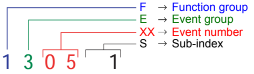
Event numbering display
F E XX S
F Function group; E Event group
XX Event number S Sub index
The first two characters “F, E” refer to the category. The middle
two digits “XX” refer to the event. From these two digits the range:
• 1 to 50 describes standard events (uniform basic events)
which can occur in any function group.
• 51 to 99 describes specific events.
The event is described in further detail through the last characters
“S” (single digit / multi-digit).
This process ensures that a unique number is assigned to each
event. Example:
0 Fault reset or
no fault
1 General fault / additional functions
Example:
Logic error, e.g. both directions selected simultaneously
2 Current
(input interface, device-internal, output interface)
3 Voltage
(input interface, device-internal, output interface)
4 Temperature
5 Hardware
Example: Output transformer short circuit, EEPROM not
responding, …
6 Software
(internal software, application software, data record /
parameters)
Example: EEPROM data error
7 Additional modules
8 CAN monitoring
9 External fault
Example: ISM
See also: Jungheinrich Service Repair Manuals PDF
Jungheinrich Error Codes Manual PDF
Password: https://truckmanualshub.com/
| Title | File Size | Download Links |
| Jungheinrich EJC112 / E1202 Event Messages Codes List PDF [PDF] | 616.6kb | Download |
| Jungheinrich Error Codes List PDF [PDF] | 198.4kb | Download |
| Jungheinrich Fault Codes [PDF] | 769kb | Download |
| Jungheinrich LISTADO ERRORES [PDF] | 198.4kb | Download |
| Jungheinrich System Error Codes list [PDF] | 162.3kb | Download |
Jungheinrich system error table
| Error | Description | Component | Display text | Cause / Action | Effect |
| 1 | Low voltage during system start | F, H, L,
F-AC, H-AC |
Low voltage ELECTRICAL SYSTEM | Check battery voltage, charge battery; Check wire connection to controller; check main current fuse; check main contactor; replace control part; Replace component;
(Limit VN = 80V: VBatt < 64V or VCap. < 56V Limit VN = 48V: VBatt < 34V or VCap. < 34V Limit VN = 24V: VBatt <17V) |
Travel is inhibited.
Reduced power for travel and lifting. Warning symbol flashing (Else-Check). |
| 2 | Over voltage | F, H, L,
F-AC, H-AC |
Over voltage BATTERY CONTROLLER | Check battery voltage; replace controller part; replace component; (Limit VN = 80V: VBatt > 92 V
Limit VN = 48V: VBatt > 62 V Limit VN = 24V: VBatt > 28 V) |
No travel or hydraulic functions Warning symbol
flashing (Else-Check). |
| 3 | Temperature limit for controllers
> 80°C (>70°C MP1510C) or ACS only: Info at > 85°C Err at > 115°C Err at < -20°C |
F, H, L,
F-AC, H-AC |
TEMPERATURE CONTROLLER | Check sensor and wire connections Allow controllers to cool down; check fan operation, improve cooling.
Warm up the controller and operate at reduced level until the controller has warmed up. |
Reduced power for travel and lifting.
Warning symbol flashing (Else-Check). |
| 4 | Emergency Disconnect applied during travel | F | POWER SUPPLY | Warning
(V < 20V MP1510C) |
Brake applies, travel inhibited |
| Error | Description | Component | Display text | Cause / Action | Effect |
| 1 | Low voltage during system start | F, H, L,
F-AC, H-AC |
Low voltage ELECTRICAL SYSTEM | Check battery voltage, chargebattery; Checkwireconnectiontocontroller; check main current fuse; check main contactor; replace control part; Replacecomponent;
(Limit VN = 80V: VBatt < 64V or VCap. < 56V Limit VN = 48V: VBatt < 34V or VCap. < 34V Limit VN = 24V: VBatt <17V) |
Travel is inhibited.
Reduced power for travel and lifting. Warning symbol flashing (Else-Check). |
| 2 | Overvoltage | F, H, L,
F-AC, H-AC |
Overvoltage BATTERY CONTROLLER | Check battery voltage; replace controllerpart; replace component; (Limit VN = 80V: VBatt > 92 V
Limit VN = 48V: VBatt > 62 V Limit VN = 24V: VBatt > 28 V) |
No travel or hydraulic functions Warning symbol
flashing (Else-Check). |
| 3 | Temperature limit for controllers
> 80°C (>70°C MP1510C) or ACS only: Info at > 85°C Err at > 115°C Err at < -20°C |
F, H, L,
F-AC, H-AC |
TEMPERATURE CONTROLLER | Check sensor and wire connections Allow controllers to cool down; check fan operation, improve cooling.
Warm up the controller and operate at reduced level until the controller has warmed up. |
Reduced power for travel and lifting.
Warning symbol flashing (Else-Check). |
| 4 | Emergency Disconnect applied during travel | F | POWER SUPPLY | Warning
(V < 20V MP1510C) |
Brake applies, travel inhibited |
| Error | Description | Component | Display text | Cause / Action | Effect |
| 5 | Over voltage | F, F-AC, H-AC | ELECTRICAL SYSTEM | Check wire connection to battery, check Battery, replace controller part; Replace component;
(Limit for Retrak: VBatt > 62 V Limit for MP1510C: V > 32 V) |
Brake applies, travel inhibited |
| 6 | Wire breakage:
– Travel set point device |
C, I2, I3, I4, I5,
Travel switch |
TRAVEL SWITCH | Check wire connection; Replace travel set point device; Replace Canion/ Interface; | Travel stop. “Warning” symbol flashes (Else-Check). Hydraulic functions possible |
| 7 | Key switch applied during travel | F,F-AC,H-AC | KEY SWITCH | Warning
(V < 13V for 200ms MP1510C) |
Brake applies, travel inhibited |
| 8 | 2 travel directions applied simultaneously | F-AC, H-AC, C,
MP, S, I2, I3, I5, FS |
ELECTRICAL SYSTEM | Warning, replace travel direction switch, replace Interface 7 Canion; replace Multi-pilot / Solo-pilot
For twin pedal, check the electrical system. |
Travel stop. “Warning” symbol flashing (Else-Check).
Hydraulic functions possible |
| 9 | Operator protection switch faulty | I2, FS | ELECTRICAL SYSTEM | Check switch, check wire connections | |
| 10 | V Cap. <> V Batt; (main
contactor jammed or not open) |
F, H,
F-AC, H-AC L |
MAIN CONTACTOR | Check main contactor, check wire connection; check output pin 2 (ACS) of traction controller; replace component | No travel, hydraulics Warning symbol
Flashing warning (Else-Check). |
| 11 | Offset error armature / field current (DC) Stator current (AC); Current measurement
point |
F, H, L,
F-AC, H-AC |
CONTROLLER | Check main current wire, replace component | Travel no function |
| 12 | Disable driver field rheostat faulty for DC Disable driver power stage faulty (for AC) | F, H
F-AC, H-AC L |
CONTROLLER | Replace component;
for AC: Check flat belt wire connection; replace power part |
No travel, hydraulics Warning symbol
Flashing warning (Else-Check). |
| Error | Description | Component | Display text | Cause / Action | Effect |
| 13 | Disable Watchdog field faulty | F, H | CONTROLLER | Replace components | Travel no function |
| 14 | – Main contactor not closed
– Field power stage cannot be switched on (DC) |
F, H,
F-AC, H-AC |
CONTROLLER/ MAIN CONTACTOR | Check wire connection; check main contactor; check charging connection, Check field supply fuse,
Replace component. |
No travel, hydraulics Warning symbol
Flashing warning (Else-Check). |
| 15 | Disable field faulty; Illegal address (for AC) | F, H,
F-AC, H-AC L |
CONTROLLER | Replace control part; replace component | Travel no function |
| 16 | Disable driver armature
actuator faulty; Software reset (for AC) |
F, H,
F-AC, H-AC |
CONTROLLER | Replace control part (AC); replace component | Travel no function |
| 17 | Disable Watchdog armature faulty | F, H | CONTROLLER | Replace components | Travel no function |
| 18 | DC: Armature power stage cannot be switched on
AC: one of the 3 phases cannot be switched on |
F, H, F-AC, H-AC L | CONTROLLER | Check armature wire connection; replace power part; replace component | Travel no function |
| Error | Description | Component | Display text | Cause / Action | Effect |
| 19 | Disable armature faulty; Power stage short circuit (for AC)
The error may be triggered by the faulty speed sensor in connection with AS4814Plus controllers. Sensor wheel wobbles (elliptical) or the sensor- sensor wheel gap is too big. In this case the component is not faulty. A short circuit cannot be resolved by switching the truck off/on. |
F, H, F-AC ,H- AC,
L-AC |
CONTROLLER | Replace power part; Replace component.
Can occur in connection with error 70, in this case: check power supply behind the main contactor contact, in the event of an error the voltage will be much lower here than the rated operating voltage. Disconnect the positive supply from the components to target the error cause. The exception here is the F1 traction controller which must remain connected. One component overloads the testing voltage due to internal short circuit. The testing voltage arises by charging the internal capacitor batteries via a resistor to the level of the control voltage supply. |
Travel no function |
| Check sensor, replace sensor and / or sensor wheel. | |||||
| 20 | Armature incorrectly connected | F, H | ELECTRICAL SYSTEM | Check armature main current wire connection | Travel no function |
| 21 | Armature over voltage (short circuit / high side faulty) | F, H, F-AC, H-AC L | CONTROLLER/ ELECTR | Check main current wire to armature; check settings(for AC);
A Armature > 360A for 250ms (MP1510); Replace component. |
| Error | Description | Component | Display text | Cause / Action | Effect |
| 22 | Watchdog error; Watchdog does not run out | F, H, L, M, S, A, I2, I3, I4, C,
F-AC, H-AC, FS |
CONTROLLER/ CANION | Truck reset,
Replace controlpart; replace component |
No travel, hydraulics Warning symbol
Flashing warning (Else-Check). |
| 23 | – Computer overload
– Permanent interrupt – “ACS” timeout on CAN connection |
F, H, L, M, S, A, I2, I3, I4, C,
F-AC, H-AC, FS |
CONTROLLER / CAN | Check CAN bus connection; Check CANION connector and component;
Replace component |
No travel, hydraulics Warning symbol
Flashing warning (Else-Check). |
| 24 | EEPROM cannot be contacted / parameters not plausible / parameter set to default
Faulty checksum |
F, H, L, I2, I3, I4, C,
F-AC, H-AC MFC brake MFC hydr. , travel switch |
CONTROLLER/ CANION | Check battery cable; check VBatt; set trucktype, set default parameters; replace control part; replace component
Delete logbook, change parameters, set hourmeter, replace component |
Flashing warning symbol (Else- Check). |
| 25 | No telegrams:
– no logon from interface – no telegrams from Can-Bus travel switch |
F, H, I4, I8
F-AC, H-AC L |
INTERFACE / CAN | Check CANBus connection, check wire connection between proportional valve
– modulation; check fuse 1F8; replace iInterface (I2, I4, I8) ; replace lift potentiometer, Multipilot, Solopilot or interface; MP1510C: Voltage collapses, controller logs on again, interface does not, controller remains blocked and waits for interface. Check battery voltage (with load!); charge or replace battery if necessary; AS2409K: no “live” telegram received from CAN Bus travel switch for more than 300 ms; replace travel switch |
| Error | Description | Component | Display text | Cause / Action | Effect |
| 26 | Wire breakage:
– Lift potentiometer |
M, S, I2, I3 | MULTIPILOT / SOLOPILOT / LIFT POTENTIOMETER | Check wire connection | Lift stop. “Warning” symbol flashes (Else-Check), travel enabled |
| 27 | Wire breakage:
– Steering setpoint device; à Reach truck: for 45° steering bolster movement no flank from proximity switch. à Canion: “Steer angle acquire active” parameter has incorrect value à Juniors PM2402L: “Operating mode” parameter incorrectly set |
C, L, I3, I4 | STEER ACTUAL ANGLE | Check wire connection; Replace steer angle sensor / potentiometer;
Replace Canion / Interface; Replace steering; PM2402L from software version 1.60: set parameter P511 “operating mode” correctly à 1 = analog sensor (potentiometer), 2 = digital sensor on steer motor |
Crawl speed,
Flashing warning symbol (Else- Check), hydraulic functions enabled. This error produces an emergency stop on the reach truck and the Juniors. |
| 28 | Wire breakage:
– Steering sensor |
C, L, I3, I4 | STEER NOMINAL ANGLE | Check wire connection, replace steering wheel sensor;replace Canion / interface; replace steering | Crawl speed,
Flashing warning symbol (Else- Check), hydraulic functions enabled. This error produces an emergency stop on the reach truck |
| 29 | Wire breakage:
– Traverse potentiometer |
M | Traverse nominal value MULTIPILOT | Replace Multipilot | |
| 30 | Wire breakage:
– Tilt potentiometer |
M | Tilt nominal value MULTIPILOT | Replace Multipilot,
Teach Multipilot (Hall sensor 2003 only) |
|
| 31 | Wire breakage:
– ZH1 setpoint device – Initial lift / lower Setpoint device |
M, S
Travel switch |
Sideshift nominal value MULTIPILOT / SOLOPILOT | Replace Multipilot / Solopilot, Teach Multipilot (Hall sensor 2003 only);
Travel switch: Check / replace switch |
Hydraulic functions stop, “Warning” symbol flashes (Else-Check), travel enabled |
| Error | Description | Component | Display text | Cause / Action | Effect |
| 32 | Wire breakage:
– ZH2 setpoint device |
M, S | MULTIPILOT / SOLOPILOT | Replace Multipilot / Solopilot,
Teach Multipilot (Hall sensor 2003 only) |
Hydraulic functions stop, “Warning” symbol flashes (Else-Check), travel enabled |
| 33 | Wire breakage:
– ZH3 setpoint device |
M, I8 | MULTIPILOT | Replace Multipilot | |
| 34 | CANBus damaged | F, H, L, M, S, A,
I2, I3, I4, I5, C, F- AC, H-AC Travel switch |
CAN-BUS | Check CAN bus connection; replace faulty component; Check terminal resistances | No travel, hydraulics Warning symbol
Flashing warning (Else-Check). Only stored in logbook (from 2004). |
| 35 | No travel zero position Deadman and accelerator pedal applied when truck switched on | I2, I3, I4, C
Travel switch |
TRAVEL ZERO POSITION | Warning, check travel switch; Intermittent contact in interface power supply (12 volts)
Check Canion, for twin pedal check electrical system |
Travel stop,
Flashing warning symbol (Else- Check), hydraulic functions enabled. |
| 36 | No lift zero position | M, I2, I3,FS | LIFT ZERO POSITION | Warning, check lift setpoint device. | Hydraulic functions stop, “Warning” symbol flashes (Else-Check), travel enabled |
| 37 | No steering angle nominal value | L | CONTROLLER / CAN | Check steering setpoint device;Check CANBus connection; check “steer type” parameter; Replace component (I5) | |
| 38 | Component does not log on, self test not concluded. | F, H, L, I2, I3, I4,
C, A, M, S, F-AC, H-AC |
CONTROLLER / CAN | Check CAN-Bus connection and voltage; check DIL switch 7 encoding (MP1510); steering controller monitoring activated? (AS2412F); check ACS encoding; replace component | No travel, lifting Warning symbol
Flashing warning (Else-Check). |
| Error | Description | Component | Display text | Cause / Action | Effect |
| 39 | Implausible truck type
1. Discovered during the self test phase that at least one component has a different truck type as a parameter. A different truck type was discovered in operating mode. Caused by intermittent contacts in the power supply connections |
F, H, L, I2, I3, I4, I5, A, M,
F-AC, H-AC |
TRUCK TYPE | For 1. Set truck type;
For 2. Examine and if necessary replace switch (key switch) or rectify intermittent contact in power supply plug connections. Set truck type. |
|
| 40 | Motor overtemperature Traction motor overtemperature in operating mode.> 150°C And travel speed < 1km/h For ACS:
Info > 145°C Err > 165°C |
L, F, H
F-AC, H-AC |
TEMPERATURE MOTOR | Warning; check motor sensor system and wire connections;
Check motor; traction motor brake open? |
Reduced power for travel and lifting.
Warning symbol flashing (Else-Check). For steering only warning symbol flashing. |
| 41 | Brake magnet potentiometer Potentiometer voltage less than 0.3 volts or greater than 2.7 volts for more than 500ms. | L | BRAKE MAGNETPOTENTIOM ETER | Check potentiometer; check potentiometer attachment; check wire connection |
| Error | Description | Component | Display text | Cause / Action | Effect |
| 42 | – Short circuit between the output and battery positive. (EJC, ELE)
-Brake magnet control, below minimum difference on potentiometer for 500ms when magnet applied. (150mV ) No brake pressure during initialization. Brake pressure after the Emergency Stop magnet has applied; |
L,F | BRAKE MAGNET | Check wire connection, check brake
magnet; replace component |
|
| 43 | Adjust brake | L | ADJUST BRAKE | Adjust brake; check potentiometer | |
| 44 | -Brake not connected or connection wire short circuit
-Brake cable torn Only for steer category_3: Internal driver of fail safe brake cannot connect the relay Or short circuit bypass (contact jams) on the output during power up test |
L,F | BRAKE FAULTY | -Check brake wiring, replace brake if necessary
-Replace brake cable, check potentiometer; Check potentiometer attachment; Only for steer category_3: -Check brake driver output, check switch contact plausibility, Replace steer component. |
No release |
| Error | Description | Component | Display text | Cause / Action | Effect |
| 45 | Too many pulses from steering set point device Intermittent contact or perturbing radiation.
More than 255 pulses identified within 100ms |
L,I5 | STEERING WHEEL | Check wire connection, replace sensor bearing; replace component | |
| 46 | Steering set point device wrongly connected AS4803L: More than 3 pulses identified in one direction and more than 3 pulses in another within 100ms. | L,I5 | STEERING WHEEL | Check sensor bearing connection; check wire connection AS4803L: Check steering wheel recognition input. | |
| 47 | No pulses from steer set point device ETVQ steering wheel no pulses from 1st sensor bearing. More than 10 pulses were obtained from the stepper motor but fewer than 3 pulses were counted within 200ms from the sensor bearing. | L,I5 | STEERING WHEEL | Check wire connection, replace sensor bearing; replace component | No release |
| Error | Description | Component | Display text | Cause / Action | Effect |
| 48 | Does not match the “Steering type” parameter ETVQ steering wheel no pulses from stepper motor or 2nd sensor bearing.
More than 10 pulses were obtained from the sensor bearing but fewer than 2 pulses were counted within 200ms from the stepper motor sensor bearing. |
L | STEERING TYPE | Set steering type correctly
ETVQ: Check stepper motor coupling, tighten grub screw. Test both setpoint device branches, set defaults and truck type Otherwise faulty, replace component. |
|
| 49 | CAN supply interrupted; Supply above 14 volts or less than 10 volts, Can or sensor bearing incorrectly
supplied |
AS 2412 F,H-AC | Can Bus CAN supply | Suply on CAN connector greater than 14 volts (electrical system short circuit, component) | Travel disabled |
| 50 | NRG Multipilot wire breakage Horizontal tilt | M | Setpoint device horizontal | Check Multipilot wire connection Parameter 540 set to 1 by mistake | Travel and lifting disabled. |
| 51 | Teach-In: steering actual value potentiometer | L | Incorrect setting SETTING | Repeat calibration, check wire connection;check potentiometer;replace component | |
| 52 | Teach-In: Brake magnet potentiometer | L | Incorrect setting SETTING | Repeat calibration, check wire connection;check potentiometer;replace component | |
| 53 | Teach-In: Steering setpoint potentiometer | L | Incorrect setting SETTING | Repeat calibration, check wire connection;check potentiometer;replace component |
| Error | Description | Component | Display text | Cause / Action | Effect |
| 54 | Motor wire breakage during power-up test ETVQ: Temperature voltage level less than 0.3 volts or greater than 2.7
volts |
L, F, H | MOTOR WIRE BREAKAGE | Check wire connection;
Check temperature sensor lines; replace component; replace motor |
|
| 55 | Motor short circuit; Current not ok; Power stage faulty | L, F-AC, H-AC | SHORT CIRCUIT MOTOR | Check wire connection; Replace motor; Replace component | Traction motor stops, Hydraulic motor stops Warning symbol
flashing (Else-Check). |
| 56 | Motor or actual value transmitter incorrectly connected | L,F.H | MOTOR REVERSE POLARITY | Check motor connection; check actual value transmitter potentiometer; AC: Phases L1,L2 or L3 swapped on motor; | |
| 57 | No actual value change Motor turns despite control signal | L,F,H | Steering controller ACTUAL VALUE TRANSMITTER | Check motor; check actual angle potentiometer; rectify mechanical wheel block;
AS4803L: Check incremental bearings; replace component; AC: Check actual value transmitter wire breakage signals PM2402L check operating mode |
|
| 58 | Steering angle actual value fluctuates
ETVQ: Reference mark 0° could not be started within 5 seconds or no valid segment reached. Steer motor does not turn |
L | STEER ACTUAL ANGLE | Check actual value transmitter (on steer motor)
Check steer motor, fuse and incremental bearing, rectify mechanical wheel block; Check proximity switch distance. |
| Error | Description | Component | Display text | Cause / Action | Effect |
| 59 | Steering angle nominal value fluctuates | L | Steer angle setpoint device
TILLER POTENTIOMETER |
Check setpoint device potentiometer (on tiller) | |
| 60 | Swivelling bolster does not follow steering wheel directions
Deviation of > 15° for 100ms The wheel turns more than 5°without change of nominal value on steering wheel, less than 2°/sec after reaching the nominal position. Tyres over-tensioned, the actual value cannot follow the nominal value. |
L | STEERING CONTROL | Check steering bolster mechanics; check chain and chain tension; check motor; check actual value transmitter attachment;
Check tyres, replace wheel if necessary. |
|
| 61 | Power stage error | L | CONTROLLER | Replace controller | |
| 62 | Power stage error | L | CONTROLLER | Replace controller | |
| 63 | Sensor power supply out of range
AS4803L: < 10V oder >16V |
L,F-AC,H-AC | CONTROLLER | The 12 volt supply not in valid range. Monitoring of 12 volt sensor supply greater than 15 volts and less than 11 volts.
Switch controller off and on, replace fuse and controller if necessary. |
|
| 64 | Software version differs | L | CONTROLLER | Different software versions in the AS4803Ls in the ETV-Q. Update software to same level. |
| Error | Description | Component | Display text | Cause / Action | Effect |
| 65 | NRG Multipilot wire breakage centre shifter | M | Centre switch MP centre shifter | Check Multipilot wire connection Parameter 540 set to 1 by mistake | Travel and lifting disabled. |
| 66 | NRG Multipilot wire breakage
180° / 360° steering toggle |
M | 180-360 switch
MP toggle switch 180°/ 360° |
Check Multipilot wire connection Parameter 543 set to 1 by mistake | Travel and lifting disabled. |
| 67 | NRG-Multipilot setpoint device travel direction switch jams on MP when system starts | M | Travel direction MP setpoint device | Check Multipilot switch, values in Judit MP teach window, recalibrate values | Travel and lifting disabled. |
| 68 | Safety switch wire breakage | I2, I3, I4, I5 | DEADMAN | Check wire connection to safety switch (deadman, seat switch); replace safety switch | |
| 69 | Both lift and lower requested simultaneously | I2, I5, FS | LIFT/LOWERSWITCH | Check wire connection; check switch | |
| 70 | Component fails to respond orresponds incorrectly to self test | F-AC, H-AC, M, S, A,
I2, C |
SELF TEST | Check displays on basic component (LED); note other error messages on basic card; Check wireconnectionsandcheck connector; check power supply behind the main contactor contact, in the event of an error the voltage will be much lower here than the rated operating voltage. Disconnect the positive supply from the components to target the error cause. One component overloads the testing voltage due to internal short circuit.
The testing voltage arises by charging the internal capacitor batteries via a resistor to the level of the control voltage supply. |
No travel, hydraulics Warning symbol
Flashing warning (Else-Check). |
| Error | Description | Component | Display text | Cause / Action | Effect |
| 71 | Lower potentiometer wire breakage | I2, FS | LOWER POTENTIOMETER | Check wire connection; replace lower potentiometer; replace Multipilot; replace interface | |
| 72 | No lowering zero position | I2, FS | LOWER RESTPOSITION | Warning, check lower setpoint device | |
| 73 | Valve output interface faulty | I2 | VALVE OUTPUT | Warning, check valve outputs | |
| 74 | Interface valve output faulty | I2 | INTERFACE FAULTY | Replace interface | |
| 75 | Proportional valve does not draw any current Correct Multipilot ?? | I2,I4,C | PROP. VALVE | Check wire connection, replace proportional valve;replace Canion / interface; replace proportional valve | Flashing warning symbol (Else- Check). |
| 76 | Proportional valve short circuit | I2, I4C | PROP. VALVE | Check wire connection, replace proportional valve;replace Canion / interface; replace proportional valve | Flashing warning symbol (Else- Check). |
| 77 | Button wire breakage | I2, | BUTTON WIRE BREAKAGE | Check wire connection; replace button; replace interface | |
| 78 | Button and travel switch pressed simultaneously | I2 | BUTTON / TRAVEL SWITCH | Warning: Check wire connection; replace button; replace interface | |
| 79 | Switch and deadman switch pressed simultaneously | I2 | BUTTON / DEADMAN | Warning: Check wire connection; replace button; replace interface | |
| 80 | 2 travel directions simultaneously | I2 | ELECTRICAL SYSTEM | Check wire connection; replace button; replace interface | |
| 81 | Different parameters for the two traction controllers | F, F-AC | MOTORS | reset parameters (EFG traction controllers) | Travel inhibited |
| 82 | Sensor wire breakage | I2 | ELECTRICAL SYSTEM | Safety height: Check wire connection; replace button; replace interface |
| Error | Description | Component | Display text | Cause / Action | Effect |
| 83 | 2 of the same components report on the truck
e.g. AS4803L: Key switch voltage cannot be assigned to components Elle_1,Elle_2 or Elle_3 |
F, H, I4, F-AC L-AC | ELECTRICAL SYSTEM | Check component encoding; check wire connection; replace component; | Travel inhibited |
| 84 | Faulty speed sensor:
à AS4803L: – Speed changes by 50% within 4ms; – Reference speed less than half the rated speed; – Steer transmission blocked; – Tear identification: a valid sensor reading is reduced to zero within 4ms and remains at this level for 50ms without producing a new valid reading. à PM2402L/2 from V1.60: – Too many pulses on encoder 3 on steer motor |
F,H,L-AC | SPEED SENSOR | Check speed sensor; Sensor bearing drift; Check wire connection; Replace speed sensor; Replace component;
Check wire routing, do not route together with motor supply wires! |
Travel stop, Lift stop,
Flashing warning symbol (Else- Check), hydraulic functions enabled. |
| 85 | Power release low voltage Travel/Steer:
Capacitor voltage drops to 30V (48V) for 0.5 seconds |
F,H-AC L-AC | ELECTRICAL SYSTEM TRAVEL | Switch truck on and off; check battery; check battery cable connections; check fuse;
Check power connections; replace component |
Travel, hydraulics no function, warning symbol
Flashing warning (Else-Check). |
| Error | Description | Component | Display text | Cause / Action | Effect |
| 86 | Improbable speed, sudden change:
à AS4803L: 2 sensor systems differ from each other. à PM2402L/2 from V1.60: Encoders 3 and 4 supply different sensor signalse |
F,H-AC L-AC | SPEED IMPLAUS | Check wire connection; Replace speed sensor; Replace component;
Pulse counts correct: 8 or 64 pulses/ revolution? Check wiring and plug connections, check wire routing, do not route together with motor supply wires! |
|
| 87 | Sensor line interrupted AS4803L: no voltage drop on a 100 Ohm internal measurement resistor MFC brake: load wheel
speed sensing |
F-AC L-AC
MFC brake |
Electrics DISCONNECTION SENSOR BEARING | Sensor wire disconnected, motor consumes maximum current and makes buzzing noise. Check sensor wires. | |
| 88 | Hydraulic speed sensor faulty on AS4814H | H (AS4814H) | SPEED SENSOR H | Check speed sensor;
Check wire connection; replace speed sensor; replace component; |
Hydraulics stop,
Flashing warning symbol (Else- Check), travel enabled. |
| 89 | Hydraulics power release low voltage | H | ELECTRICS- HYDRAULICS | Check battery, check battery wire connection;
Check fuse; replace component |
Reduced power for travel and lifting.
Warning symbol flashing (Else-Check). |
| 90 | Travel with handbrake on | C | ELECTRICAL SYSTEM | Check magnetic brake switch | Flashing warning symbol (Else- Check). |
| 91 | 24 volts out of range Info at <17 V
Err at <15 V |
C | ELECTRICAL SYSTEM | Check power supply; check wire connection | For a warning, only the warning symbol flashes (Else-Check).
For an error, the truck stops. |
| Error | Description | Component | Display text | Cause / Action | Effect |
| 92 | Wrong component reporting on Canion | M, S, A | ELECTRICAL SYSTEM | Check Master/Solopilot; check display; replace component
Check jumper in XB 27 and XB 44 from pin 2 to pin 6, |
Travel, lifting
function, warning symbol flashes (Else-Check). |
| 93 | ACS capacitors not charged | F, H, C | ELECTRICAL SYSTEM | Check charging connection, main contactor
does not apply, check bus voltage, check transformer, fuses and cable set, Replace component |
Travel, lifting no function, warning symbol flashes (Else-Check). |
| 94 | SDO error | F, H, C | SDO ERROR | Software incompatible check software version
Reload software. Check jumper in XB 41 from pin 12 to pin 13. |
Travel, lifting no function, warning symbol flashes (Else-Check). |
| 95 | Pin code error | C | PIN CODE ERROR | Component pin codes not identical | Travel, lifting no function, warning symbol flashes (Else-Check). |
| 96 | No zero position for hydraulics Masterpilot, Solopilot, | M,S | Hydraulics zero position MP/SOLOPILOT | Check Master/Solopilot; lift, lower, tilt, ZH1, ZH2, ZH3, horn switch not in zero position
Replace component |
Hydraulic functions stop, “Warning” symbol flashes (Else-Check), travel enabled |
| 97 | Segment beyond tolerance limits
à PM2402L/2 from V1.60: Referencing error on power up, no switch signal from proximity switch (NS) or time interval exceeded |
L | FAULTY SEGMENT | Segment on swivelling bolster not within tolerance level.
Check wiring and proximity switch, check distance from switch to trip cam on swivelling bolster |
| Error | Description | Component | Display text | Cause / Action | Effect |
| 98 | The position of the sensor bearing and proximity switch (segment) deviate by more than 1.1 degrees. When the truck starts up, the direction of rotation from the steering wheel sensor system to the motor power connection or the steer motor sensor system is inversed.
à PM2402L/2 from V1.60: Referencing error during operation, unexpected switch signal from proximity switch. |
L | POSITION DEVIATION | Check wiring.
Check wiring and proximity switch, check distance from switch to trip cam on swivelling bolster |
|
| 99 | CANBus damaged; CANBus driver temporarily deactivated | F,H,M,S,A, I3, I4, C | CAN-BUS | Check wire connection, check terminal resistors, install truck anti- interferencemeasures; | Travel, hydraulics no function, warning symbol flashes (Else-Check). |
| 100 | NRG software versions of internal component parts
implausible |
M | Multipilot software | Replace component part with corresponding component, as flashing currently not possible in the
field. |
| Error | Description | Component | Display text | Cause / Action | Effect |
| 101 | Input / output error | JUBES | Jubes input/output | Check I/Oa, rectify contact error, check operating voltage, replace external transmitter
Index info in display: a— Sensor 1 supplies values, but not defined. Check parameters 11-17 b— Sensor 2 supplies values, but not defined. Check parameters 20-26 c— Sensor 3 supplies values, but not defined. Check parameters 29-35 Or a sensor 1-3 supplies a voltage outside the range of 0.5V – 9.5V. |
Shown in the driver’s display with error 101 |
| 102 | Internal error | JUBES | Jubes internal | Check operating voltage. Index info in display:
a — Communication between access module and data recording faulty, check connection e — Radio module faulty f — Radio channel number is “0”, should be >0, check parameter 100 g — Radio transmitting power is “0”, Check parameter 101 h — Lock number is invalid, replace access module i — Impact sensor faulty, replace data recorder |
Shown in the driver’s display with error 102 |
| Error | Description | Component | Display text | Cause / Action | Effect |
| 103 | Parameter error | JUBES | Jubes parameters | Set parameters Index info in display:
a — Parameter 5 greater than parameter 6, should be smaller. b — Differential value of parameter 11 is greater than the differential values of the various stages of parameters 12-17 c — Differential value of parameter 20 is greater than the differential values of the various stages of parameters 21-26 d — Differential value of parameter 29 is greater than the differential values of the various stages of parameters 30-35 e — the stages of parameters 12-17 … f — the stages of parameters 21-26 … g — the stages of parameters 30-35 … h — Impact stages of parameters 47-49 … i — Impact stages of parameters 50-52 … …are not in increasing order |
Shown in the driver’s display with error 103 |
| 104 | Sensor bearing provides
no pulses on system start up |
F,H | (SENSOR BEARING) | Check sensor bearing and wire, replace sensor bearing or
controller |
|
| 105 | Motor temperature gauge
provides incorrect values Sensor line wire breakage |
F,H,L | Temp.Motor | Check sensor connection and lines, if
possible replace sensor, otherwise replace the entire motor… |
|
| 106 | Controller temperature gauge provides incorrect
values |
F,H,L | Temp. controller | Internal error, replace controller. |
| Error | Description | Component | Display text | Cause / Action | Effect |
| 107 | Key switch voltage out of range
Hardware encoding incorrect |
F,H,L
MFC hydr. MFC brake |
Electrics | Error in controller connection (Saab connector) on component | No travel No lifting No steering
Main contactor open |
| 108 | Calibration reading incorrect | F,H | (CONTROLLER
internal) |
Internal error, replace controller. | |
| 109 | Brake pedal faulty | MFC brake | BRAKE PEDAL | Brake pedal signals implausible | |
| 110 | Current output faulty | MFC brake MFC hydr. MFC option | CONTROLLER | Check outputs for short circuits | MFC_Hydr.: no lifting MFC_Brake: crawl speed only |
| 111 | Steering controller is monitored by traction controller for signs of life telegrams
Traction controller does not receive these telegrams. The Can Bus is overloaded. |
F | Steering controller | Check steering controller | Travel inhibited Main contactor open |
| 112 | Steering controller_2 is monitored by traction controller_1 for signs of life telegrams
The Can Bus is overloaded. |
F | Traction controller | Check Can Bus, measure terminal resistor 60Ohm | |
| 113 | Lift controller does not send lift telegrams | H | LIFT CONTROLLER | ||
| 114 | No traverse distance reference on power up | MFC hydr. | Info 32
Traverse reference |
None | Reduced traverse speed until both stops have been reached once. |
| Error | Description | Component | Display text | Cause / Action | Effect |
| 115 | Main contactor improbable,
contacts not closed. Wire connection interrupted, faulty main contactor driver on traction controller |
F,H,L
?? |
Main contactor improbable | Check wire connection.
If error 19 is also present, disconnect the shorted power stage Disconnect the power positive. Check driver voltage (switched against negative). If reading OK, check contactor coil and mechanics. |
No truck functions |
| 116 | After software flashing (field operation), the item number of the software is implausible and parameters may also be implausible. | F,H,
MFC brake MFC prop |
Info 54
SET TRUCK TYPE |
Set truck type and switch truck off / on (wait approx. 35 seconds).
On request, automatically: all parameters are set to default, the software item number is set to plausible, the log book is deleted, the hourmeter set to zero and entry 116 made in the log book. |
In the log book only error 116 stands as a marker for this process and all parameters can be at default. |
| 117 | Cab position implausible, rotary potentiometer value does not match 180
degree switch |
CANION | Cab position | Check rotary potentiometer, re-adjust if necessary, check 180 degree switch | No TRAVEL release |
| 118 | Steering controller reports error | L | Steering controller | Check display on steering controller | TRAVEL inhibited, EMERGENCY STOP activated |
| 119 | Weigher button faulty | MFC brake | Button faulty | Check wire and button | Weighing interrupted |
| 120 | Weigher pressure sensor faulty | MFC hydraulics | Sensor faulty | Check wire and sensor | Weighing interrupted |
| 121 | Battery incorrectly locked | F-AC | Battery lock | Locking strips stuck. Check proximity switch | No truck functions |
| 201 | Optical sensor faulty | Rack height select | sensor |
| Error | Description | Component | Display text | Cause / Action | Effect |
| 202 | Too many reference points during calibration | Rack height select | Calibration wrong | ||
| 203 | Sensor evaluation improbable | Rack height select | sensor | ||
| 204 | Error when reading EEPROM | Rack height select | Controller | All settings set to default | |
| 205 | No Multipilot in truck | Rack height select | MP missing | ||
| 240 | Internal process interrupted | Rack height select | Controller | ||
| 250 | No height actual value on job input | Rack height select | The height is invalid for the warehouse level entered | ||
| 252 | Rack height select incorrect | Rack height select | |||
| 253 | Rotary field implausible –
transmission overloaded, excess load on incline |
F | Controller | None, switch truck off/on | Main contactor opened |
| 254 | Diagnostics piratry | Judit Box | None | Create authorisation | No diagnosis possible |
Components
| A | C = 064 | Display / Operation (LISA / JULIA) |
| C = 065 | Display / Operation (Else-Check) | |
| C = 066 | Display/Operation (CANCode) | |
| C = 067 | Display (CANDis) | |
| C = 068 | Display/Operation (on board computer) | |
| C = 3 | Comfort display [CANopen] | |
| C | Canion (Atlas Copco) [CANopen] | |
| C = 1 | – Master | |
| C = 11 | – Slave | |
| F | C = 016 | Travel (MP1510C / AS2405F / AS2409K / AS2412F) |
| C = 016 | Travel 1 (MP1514F / AS4814Fplus) | |
| C = 017 | Travel 2 (MP1514F / AS4814Fplus) | |
| F-AC | C = 016 | Travel (AS4812/14F) |
| C = 8 | ACS Traction (Atlas Copco AC 8011/18, Inmotion) [CANopen] | |
| Travel switch | C = 096 | Can-Bus travel switch |
| H | C = 032 | Lift (MP1514H / AS4814Hplus) |
| H-AC | C = 032 | Lift (AS4814H) |
| C = 7 | ACS Pump (Atlas Copco AC 8011/18, Inmotion) [CANopen] | |
| Rack height select | C = 128 | Rack Select |
| I | C = 21 | I/O-Board 1 [CANopen] |
| C = 22 | I/O-Board 2 [CANopen] | |
| C = 23 | I/O-Board 3 [CANopen] | |
| C = 24 | I/O-Board 4 [CANopen] |
| I2 | C = 146 | Interface 2 |
| C = 155 | Interface 21 | |
| C = 156 | Interface 71 | |
| I3 | C = 147 | Interface 3 |
| I4 | C = 148 | Interface 4 = MFC_brake |
| I5 | C = 149 | Interface 5 |
| I6 | C = 150 | Interface 6 = MFC_Prop |
| I7 | C = 151 | Interface 7 |
| I8 | C = 152 | Interface 8 = MFC_Option |
| Jubes | C = 069 | ISM Access Module |
| C = 29 | ISM Access Module [CANopen] | |
| C = 070 | ISM-Data recorder | |
| C = 071 | ISM-radio module | |
| L | C = 048 | Steer (MP1502L / PM2402L / AS4803L) |
| C = 048 | Steer 1 (AS4803L) | |
| C = 049 | Steer 2 (AS4803L) | |
| C = 050 | Steer 3 (AS4803L) | |
| C = 4 | Steer computer [CANopen] | |
| M | C = 096 | Multipilot / Masterpilot |
| C = 2 | Multipilot / Solopilot [CANopen] | |
| S | C = 112 | Solopilot / Hand lever |
Travel setpoint device: travel potentiometer, accelerator pedal
Steering actual value transmitter: steer potentiometer, proximity switch (on steered wheel)
ONLY in 1st generation!
All messages numbered above 100 come from the interface and correspond to messages 1- xx -99!
| Warning / Information Messages | |||||
| INFO 01 | SEAT SWITCH_OPEN | ||||
| INFO 02 | NO_TRAVEL DIRECTION | ||||
| INFO 03 | NO_TRAVEL RELEASE | ||||
| INFO 04 | NO_NOMINAL VALUE | ||||
| INFO 05 | LIFTING OFF | ||||
| INFO 06 | DEADMAN KEY OPEN | ||||
| INFO 07 | START_INCORRECT | ||||
| INFO 08 | PARKING BRAKE | ||||
| INFO 09 | SLOW SPEED | ||||
| INFO 10 | TEMPERATURE DRIVE MOTOR | ||||
| INFO 11 | TEMP_LIFT_MOTOR | ||||
| INFO 12 | TEMP_STEER_MOTOR | ||||
| INFO 13 | BRUSH WEAR OUT_DRIVE_MOTOR | ||||
| INFO 14 | BRUSH WEAR OUT_LIFT_MOTOR | ||||
| INFO 15 | BRUSH WEAR OUT_STEER_MOTOR | ||||
| INFO 16 | DRIVING DISABLE | ||||
| INFO 17 | LIFT END DIS. | ||||
| INFO 18 | SECURITY HEIGHT | ||||
| INFO 19 | DOOR OPEN | ||||
| INFO 20 | AISLE MODE | ||||
| INFO 21 | RESCUE STEERING | ||||
| INFO 22 | STEERING MISSING | ||||
| INFO 23 | DIAGNOSTIC_MODE | ||||
| INFO 24 | SWITCH POWER OFF | ||||
| INFO 25 | TEMP_TRAVEL | ||||
| INFO 26 | TEMP_LIFT | ||||
| INFO 27 | TEMP_STEER | ||||
| INFO 28 | SPARE_1 | ||||
| INFO 29 | DISPLAY SWITCHES THE EXTERNAL
BUZZER |
| INFO 30 | TWIN PEDAL BOTH APPLIED | ||||
| INFO 31 | NO ZERO POSITION | ||||
| INFO 32 | NO TRAVERSE REFERENCE ON POWER UP | ||||
| INFO 33 | ONLY CRAWL SPEED POSSIBLE AS
BATTERY NOT LOCKED |
||||
| INFO 34 | ONLY CRAWL SPEED POSSIBLE, AS INFO
FROM STEERING CONTROLLER |
||||
| INFO 35 | LOW VOLTAGE TRAVEL | ||||
| INFO 36 | LOW VOLTAGE LIFT | ||||
| INFO 37 | LOW VOLTAGE STEER | ||||
| INFO 40 | CHECK MOTOR SENSOR SYSTEM | ||||
| INFO 48 | IMPACT EVENT VERTICAL FORCE 1 | ||||
| INFO 49 | IMPACT EVENT VERTICAL FORCE 2 | ||||
| INFO 50 | IMPACT EVENT VERTICAL FORCE 3 | ||||
| INFO 51 | IMPACT EVENT HORIZONTAL
FORCE 1 |
||||
| INFO 52 | IMPACT EVENT HORIZONTAL
FORCE 2 |
||||
| INFO 53 | IMPACT EVENT HORIZONTAL
FORCE 3 |
||||
| INFO 54 | SET TRUCK TYPE | ||||
| INFO 73 | CHECK VALVE OUTPUTS |
Stamford, CT, United States
Rental giant United Rentals has reported record rental revenues, up 18.8% in the last quarter of 2022. Used equipment sales were also up, increasing 26.2% year-over-year. Releasing the financials…
Casimir Lindholm, Cargotec
Andreas Krause, Clark Europe
Louisa Hosegood, Logistics UK
Various, Hoppecke UK
Forklift Diaries

Last Week’s Most Read
Movers & Shakers
president and CEO
Cargotec,
Finalnd
resigned
Clark Europe,
Germany
director
Logistics UK,
United Kingdom
various
Hoppecke UK,
United Kingdom
In the Discussion Forums
At Cascade Corporation, we know the forks and attachments used to handle your loads are essential to keeping your material handling operations running smoothly. That’s why selecting products that integrate seamlessly with each other (and your workflow) can be a time-consuming and difficult task.
Sensortronic Weighing & Inspection Australasia (SWIA) is an industry leader in weighing measurement solutions and is an exclusive agent for the Compuload range of products.
In the Virtual Expo

Genkinger manufactures handling equipment for cable and rope reels with dimensions and weights ranging from 500 to 50,000kg, based on a modular system to suit your needs.
Port of Spain, Trinidad And Tobago
The Port of Port of Spain (PPOS) has purchased two Konecranes Liftace empty container handlers, a Konecranes reachstacker, and two Konecranes forklifts for its port terminal located in Port…
Washington, DC, United States
The acquisition of Myers Forklift in December was the fifth materials handling purchase by BMH Equipment in 12 months. Myers joins Frank H. Gill & Co. (Lansing, IL); Mass Lift…
Special Feature

Latest Jobs
Dallas, TX, United States
Evansville, IN, United States
Movers & Shakers
president and CEO
Cargotec,
Finalnd
resigned
Clark Europe,
Germany
director
Logistics UK,
United Kingdom
various
Hoppecke UK,
United Kingdom
Password: https://www.pdfmanual4trucks.com/
|
Title |
File Size |
Download Links |
|
Jungheinrich EJC112 / E1202 Event Messages Codes List PDF |
619.4kb |
Download |
|
Jungheinrich Error Codes List PDF [PDF] |
199kb |
Download |
|
Jungheinrich Fault Codes [PDF] |
769kb |
Download |
|
Jungheinrich LISTADO ERRORES [PDF] |
199kb |
Download |
|
Jungheinrich System Error Codes list [PDF] |
162.7kb |
Download |
|
Display error code |
Cause |
Action |
|
1901 |
During system start-up, the accelerator pedal zero position could not |
Do not press the accelerator pedal during system start-up. |
|
1904 |
Accelerator pedal pressed, but no travel direction selected. |
Take your foot off the accelerator pedal, select a travel direction and set off. |
|
1909 |
Accelerator pedal pressed and parking brake not released via parking |
Release the parking brake by pressing the parking brake button. |
|
1917 |
Accelerator and brake pedals pressed simultaneously. |
Press one pedal at a time only. |
|
2951 |
Lift function activated on multi-/ solo PILOT during system start- up. |
Do not apply the multi-/ solo PILOT during system start- up.
–
–
– |
|
1952 |
Travel direction switch pressed during system start-up. |
Do not press the travel direction switch during system start-up |
|
9961 |
ISM (option) has detected a shock event in the vertical |
Obtain acknowledgement from authorized person (warehouse manager) and |
|
9962 |
ISM (option) has detected a shock event in the horizontal |
Obtain acknowledgement from authorized person (warehouse manager) and |
|
5990 |
The electrolyte level sensor check (battery-management option) on the |
Add electrolyte. |
|
5992 |
After switching on the truck, no radio network could be established |
–
–
–
– |
|
5408/ 5409 |
Lithium-ion battery overtemperature |
Stop work. |
|
5413 |
Lithium-ion battery low temperature |
Move truck to warm environment. |
For all other warning messages switch the truck off and on again. If the warning message appears again call the service department.
The code lock enables an operator or a group of operators to be assigned an individual user code. The user code is configured with a master code and is outlined in the following sections of this
chapter.
When you have entered the valid user code the truck will be operational. The truck will be able to perform travel, steering and hydraulic operations.
When you have entered the valid master code the truck will be switched on. Travel operations are inhibited. The truck will be able to perform steering and hydraulic operations. The code lock is
in programming mode. When you enter one of the following parameters the settings in the code lock can be changed.
|
Parameters |
Description |
|
0-0-0 |
– To change the master code |
|
0-0-1 |
– To add user codes |
|
0-0-2 |
– To change a user code |
|
0-0-3 |
– To clear a user code |
|
0-0-4 |
– To clear all user codes |
|
0-1-0 |
– To set the automatic cutout of the truck |
Newly supplied trucks have the code indicated on a sticker. When using the truck for the first time change the master and user codes and remove the sticker.
- User code factory setting: 2-5-8-0
- Master code factory setting: 7-2-9-5
German-made Jungheinrich loading equipment is distinguished by excellent durability and
performance. Benefit from consistently high handling speeds with maximum comfort. This European-quality equipment perfectly adapts to various operating conditions, meets strict safety standards,
is distinguished by high working and driving qualities for moving and storing goods for work both in an open area and inside a closed warehouse or a freight railway container.
Jungheinrich LPG trucks, like trucks from other brands of this type, have a number of advantages. This is a universal warehouse
equipment, which is very economical if, when buying it, you correctly calculate the basic requirements for the height of lifting of loads, carrying capacity, speed of movement, weight of the
machine, its dimensions and, of course, the types of cargo with which the machine has to deal. If the calculation is carried out carefully, and the optimal model is chosen, the costs for it,
given the low price of gas, will pay off in a few months. And due to its high ecological class, it can work on a shift all day long with practically different cargoes that require specific
transportation conditions. The peculiarity of gas forklifts is that you can start them in any weather without any problems, which can not be said about diesel or gasoline ones.
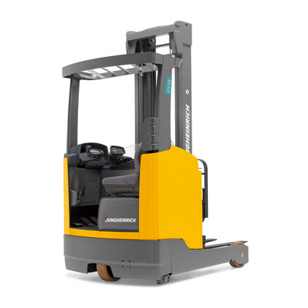
Jungheinrich electric forklift EFG 115
The EFG 115 is the most compact electric forklift from the German concern Jungheinrich. It can be used in the smallest rooms,
including wagons and wagons. It has the following technical characteristics:
The distribution of weight to the front axle is 3805/1270.
Carrying capacity — 1500 kg.
Total weight 2870 kg.
Engine:
running — 4 kW;
lifting — 6 kW.
The maximum speed is 12.5 km / h.
Clearance — 100 mm.
The wheelbase is 1200 mm.
The center of gravity of the load on the forks is 500 mm.
Mast tilt (a / b) in degrees — 5/6.
Mast — 2000-3550 mm.
Working corridor width:
across — 3114 mm;
along — 3236 mm.
The total width is 990 mm.
The total length is 2935 mm.
The service brake is hydraulic.
The maximum lifting height is 3000 mm.
The maximum climb is 16 degrees.
Fork dimensions (LxWxH) — 1150x100x35 mm.
Lifting speed with / without load — 240/500 mm / s.
Lowering speed with / without load — 580/600 mm / s.
It is worth noting that it is quite difficult to find a new Jungheinrich EFG 115 loader in the domestic market. However, these
forklifts are quite widely used, and here the price depends on the condition of the machine. In general, the cost can vary from 3,000 to 10,000 euros. The new EFG 115 will cost about 18,500
euros.
Electric forklift Jungheinrich EFG 215
The second series of EFG loaders differs from the first in a large set of technical options. All this could not but affect the cost, which will be
slightly higher than the 115 model. However, first, let’s look at the technical specifications:
The distribution of weight to the front axle is 3870/1310.
Carrying capacity — 1500 kg.
Total weight 2978 kg.
Engine:
running — 4.6 kW;
lifting — 11.5 kW.
Storage battery (voltage V / capacity kW * h) — 48/500.
The maximum speed is 16 km / h.
Clearance — 100 mm.
The wheelbase is 1249 mm.
The center of gravity of the load on the forks is 500 mm.
Mast tilt (a / b) in degrees — 7/7.
Mast — 2000-3560 mm.
Working corridor width:
across — 3104 mm;
Along — 3226 mm.
The total width is 1060 mm.
The total length is 2924 mm.
The service brake is electromechanical.
The maximum lifting height is 3000 mm.
The maximum climb is 35 degrees.
Turning radius — 1440 mm.
Fork dimensions (LxWxH) — 1150x100x35 mm.
Lifting speed with / without load — 460/600 mm / s.
Lowering speed with / without load — 550/550 mm / s.
As you can see from the technical characteristics, this car has almost the same dimensions as the previous model, but with more powerful motors and
improved other indicators.
Народ привет!
2-ой год подряд весна для меня начинается не с хорошего настроения и тепла а с очередной напасти в моем любимом коне. В том году я парился с гудяшим приводом и убитыми в круг стойками и ожиданием когда же все придет. В этот рас новый трабл.
Что произошло:
Машина за всю зиму не доставила никаких проблема, четко работали все системы. С приходом весны все еще лучше стало, единственно езда по асфальту доставляла небольшой дискомфорт, но и это не проблема.
В четверг 20.04.17 после обеда собрался ехать на работу, вышел завел, стою, смотрю когда начнет стрелка температуры расти чтобы начать движение, но замечаю что обороты не собираются падать до моих 700-800, а держаться на 1200-1300. И тут загорается ЧЕК!
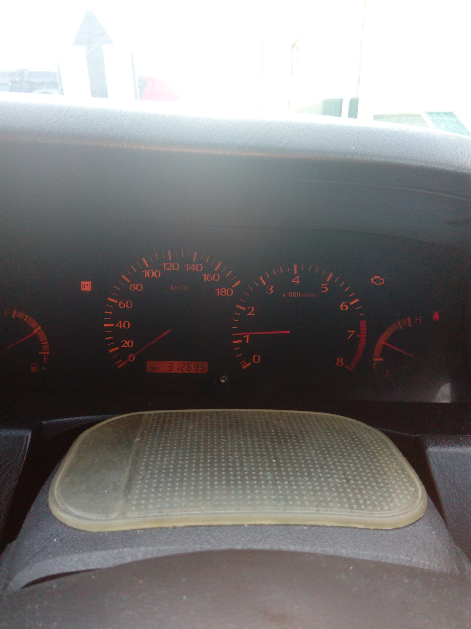
Полный размер
Первое появление проблемы, горит чек и обороты
Думаю черт, неужели снова форсы льют, была такая ситуация по осени, диагносты анонсировали что по одной стороне льет 1-2 форсы, ничего критичного пока, поездив 1,5 недели и после заправки под горлышко чек погас и не беспокоил до сегодняшнего дня.
Тут я плюнул и начал движение и был НЕ приятно удивлен, давлю газ а она набирает обороты 2000 и везет меня на 1. И все ехать нехочет вообще. Понимаю что то серьезное, сразу понял что машина перешла аварийный режим. Проехав 300 метров встал на перекрестке с неприятным ощущением, перешелкнул селектор с D на P и обратно и получаю жесткий или жестокий пинок от коробки, думаю но зашибись короба сдохла! Разворачиваюсь и обратно домой как черепаха. Поставил, сразу почему то на автомате открыл капот и сдернул клему на пару минут и поставил обратно, завел и снова такая же херь, но времени лазить нет, надо на работу. Приехав с работы через 4 часа и начитавшись интернета решил понть в чем дело, сожусь завожу, а она работает как не бывало! вот я ах***, что за нах**. Сел поехал, все норм, коробка переключает все четко, тяга есть, прет как надо, полчаса покатался потом домой, думаю ну ладно может глюк, пронесло!))) Но на всякий случай записался на следующий день на диагностику.
Суть проблемы, трабла как я подумал сначала:
И так диагностика показала 2 ошибки и обе по дроссельной заслонке 1122-привод заслонки-обратная связь, 1123-электропривод заслонки.
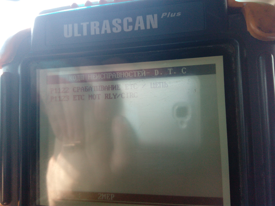
Полный размер
Фото со сканера
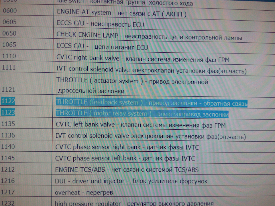
Полный размер
Расшифровка ошибок
Диагност посоветовал почистить дроссель и потом обучить его. Сам я не любитель лезть в движок в виду присутствия кривых рук=)) Решил отложить все эти процедуры на недельку в виду отсутствия денег, а также что хотел съездить в соседний г.Нижневартовск к мастерам которые обслуживали этот мотор до меня, просто понимают и знаю Ниссаны, и в принципе вызывают у меня доверие и уважение, нежели мастера в моем городе (не все, есть хорошие).
И так покатавшись 3 дня, также в обед в понедельник 24.04.17, я собрался ехать домой покушать, выхожу завожу, на улице лепота +11.
не прошло и минуты, снова та же проблема чек и обороты. Плюнул и на обед подкинул коллега.
Вечером дополз до гаража, по другому такую езду не назовешь и было решено самому чистить дроссель и обучать его. С инета нафотал кучи инфы по очистки и обучению. В целом ничего сложно все открутил, снял, ушло минут 12-15 неспешной работы. Чистил карбклинером и WD-ой. Дроссель был знатно загажен, глянул во впуск там тоже все черным черно, но до него доберемся потом.
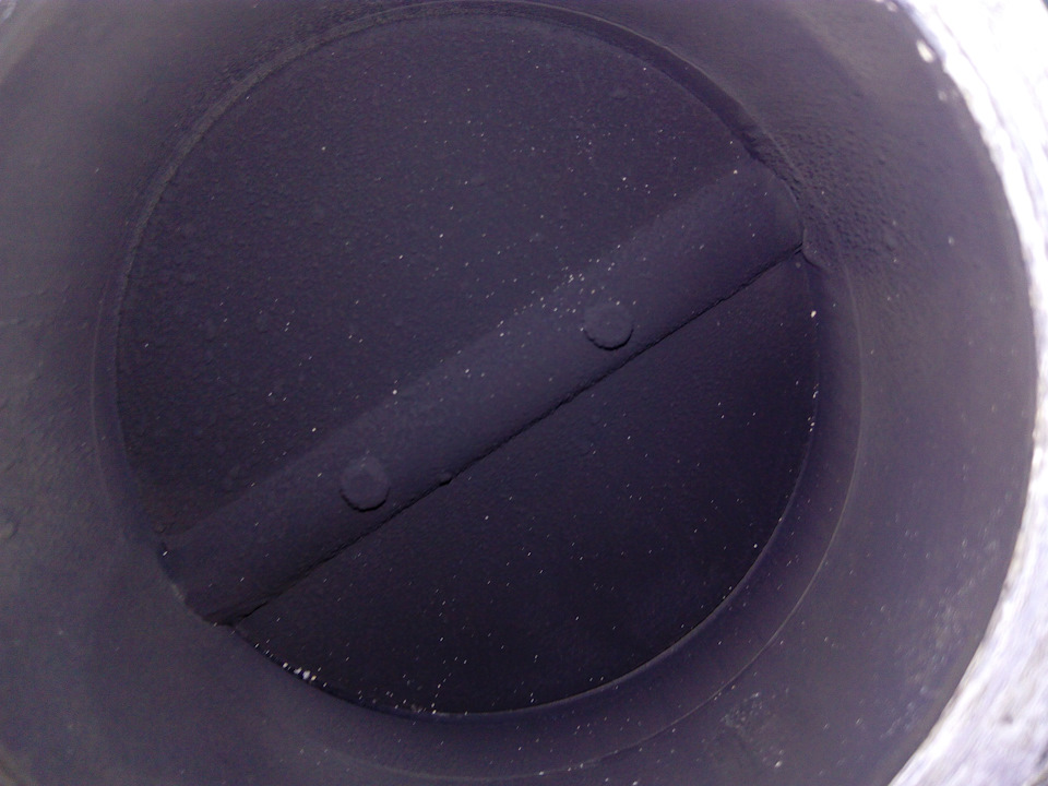
Полный размер
Собственно дроссель
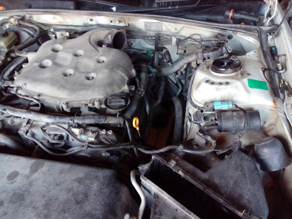
Полный размер
Двигатель со снятым дросселем
И так все более-менее почистили, собрали заново, заводи и тут машина начинает чудить, я был готов к тому что будут завышены обороты, но в моем случае эти обороты были 1600-1800! и горящий ЧЕК. Давай пробовать госить чек, как говориться народным тапковым методом, ХЕР! Все безуспешно, но зато прочитали коды ошибок между делом, все те же 1122 и 1123. 2 часа попыток и экспериментов результат не дали, обороты ахрененные, трогаться на них даже и не думал. Заглушил, закрыл гараж и пошел шерстить интернет о своей проблеме…
Суть обращения:
Народ помогите! Кто что знает? где копать суть проблемы? Как можно ее исправить?
Почитав инет для себя решил что возможно проблема в проводке или где то контакты подушатались, но и это мне скажет хороший электрик, которых у нас практически нет, а ехать в г. Нижневартовск, да машина тупо не едет! А эвакуатор конских денег стоит, так как ехать 70 км.
Надеюсь конец истории.
И так Машина неделю простояла у мастера, прежде чем он смог сосредоточиться на моей проблеме. Это были ужасные дни пешком =)). Ну так вот:
Чистка дросселя результата не дала, а ухудшила! об этом я расписывал выше, и попытки самому что то изменить (обучение дросселя тапковым методом) успехов не принесли. Я отогнал мотор к электрику в своем городе, знакомые ребята хорошо отзывались об одном мастере, мол оживил мертвеца, которого на всех СТО говорили что не машина а металлолом. И я решил обратиться к нему, забегаю вперед чувак красавец, оч умный, не занимается тупым обдираловым, оплата после успешной работы, а не то что были такие мастера которые за одно присоединение и считывание ошибок 1500 дерут а потом еще и ремонт залупят рубля 3000 а то и больше. Короче начали с простого, считали ошибки, обучили дроссель, и вроде все ГУУД! Денег не стал брать, сказал катайся неделю, если все норм, то потом расчет. Но через 3 дня снова беда, чек, обороты! В итоге пригнал снова, решено было лезть в мозги, достали и тщательно проверили, было 2 трещины, пропаяли, потом прозвонили все какие есть там контакты, мозгов с дросселем и так далее! Все звонилось, плюс нашли релюшку на дросель и заменили на новую…Завели, прогрели, ошибок нет, ХХ стал еще лучше. 2 Недели езжу тьфу тьфу тьфу все огонь!
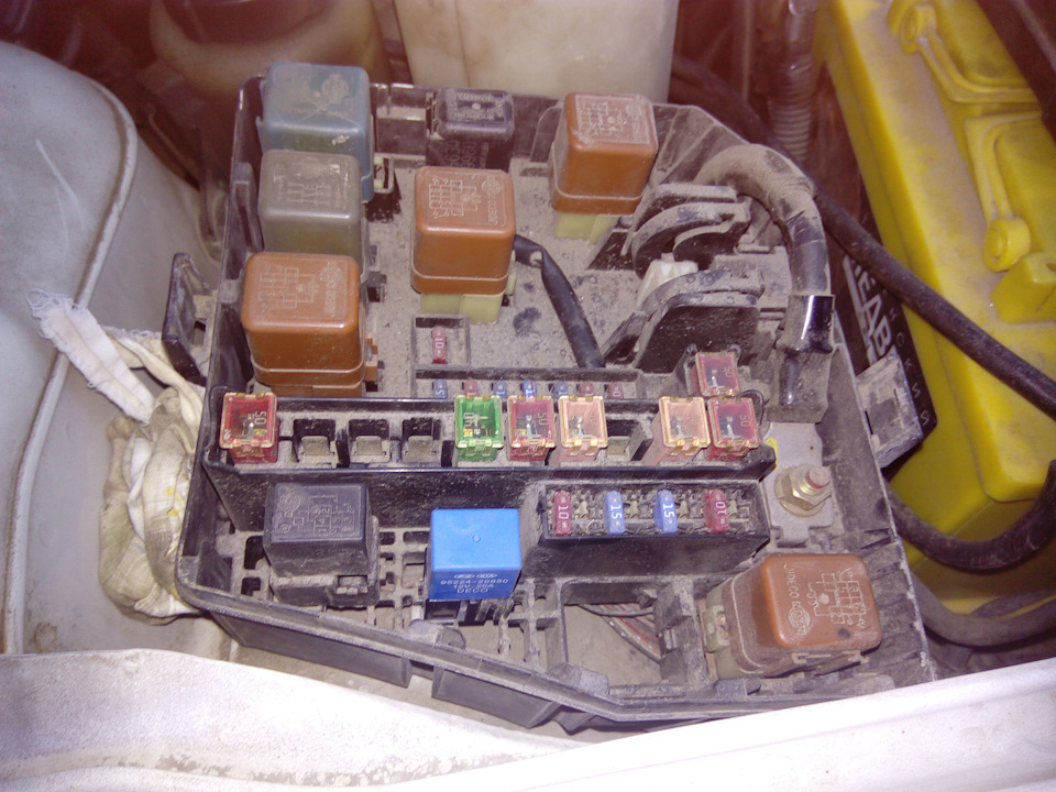
Полный размер
Синяя релюшка снизу, если всмотреться написано КИА, Хэндэ.