I have this pen where I have made an example of the SVG Sprites Technique:
And I want to apply this with CSS:
.circle {
    fill: #f00;
}
.polyline {
    fill: #00f;
}
<svg xmlns="http://www.w3.org/2000/svg"style="position:absolute;top:-9999px;opacity:0;">
<symbol viewBox="0 0 64 64" id="circle">
<title>circle</title>
<path fill="#1D1D1B" d="M32,0C14.327,0,0,14.327,0,32c0,17.673,14.327,32,32,32s32-14.327,32-32C64,14.327,49.673,0,32,0z M32,52.5c-11.322,0-20.5-9.178-20.5-20.5S20.678,11.5,32,11.5S52.5,20.678,52.5,32S43.322,52.5,32,52.5z"/>
</symbol>
<symbol viewBox="0 0 56.983 64.804" id="polyline">
<title>polyline</title>
<polyline fill="#1D1D1B" points="0,64.804 30.726,0 56.983,0 56.983,54.749 29.33,27.095 "/>
</symbol>
</svg>
<svg class="circle">
<use xlink:href="#circle"></use>
</svg>
<svg class="polyline">
<use xlink:href="#polyline"></use>
</svg>My problem is that I’m not able to change the fill color of the elements added to the spritesheet. I have looked for information about how to do this correctly and I think my approach it’s correct but it seems that it’s not like that.
In this other pen, wrote in the same way I think, is working fine. What am I doing wrong?
Sorry for my english if I have made any mistake, it’s not my native language.
![]()
Alexandr_TT
13.3k2 gold badges25 silver badges53 bronze badges
asked Aug 12, 2015 at 17:15
![]()
You have to remove internal styling of fill property and only apply css property. Either way change fill property of svg using javascript DOM.
answered Aug 12, 2015 at 17:22
![]()
0
Here is a working example: http://codepen.io/anon/pen/NqmrOR
The problem was the fill="#1D1D1B" attributes placed directly on the SVG elements.
NOTE: Using CSS class selectors on SVG elements, while supported in most up-to-date browsers, is not universally supported. Programmatically applying styles to SVG elements in JS themselves is actually better supported.
answered Aug 12, 2015 at 17:24
![]()
Ben CookBen Cook
1,6442 gold badges18 silver badges31 bronze badges
1
When using the command <use xlink: href =" # circle "> </use> the content of the SVG element goes to the Shadow DOM
Therefore, it becomes impossible to change styles with external CSS
The solution to this problem is to use forced ʻinherit` inheritance
 polyline, path {
fill:inherit;
stroke:inherit;
}
You can read more in this article: Styling SVG Content with CSS
polyline, path {
fill:inherit;
stroke:inherit;
}
 .circle {
fill:yellowgreen;
}
 .circle:hover {
fill:red;
}

.polyline {
fill:gold;
}

.polyline:hover {
fill:red;
}
<svg xmlns="http://www.w3.org/2000/svg"style="position:absolute;top:-9999px;opacity:0;">
<symbol viewBox="0 0 64 64" id="circle">
<title>circle</title>
<path fill="#1D1D1B" d="M32,0C14.327,0,0,14.327,0,32c0,17.673,14.327,32,32,32s32-14.327,32-32C64,14.327,49.673,0,32,0z M32,52.5c-11.322,0-20.5-9.178-20.5-20.5S20.678,11.5,32,11.5S52.5,20.678,52.5,32S43.322,52.5,32,52.5z"/>
</symbol>
<symbol viewBox="0 0 56.983 64.804" id="polyline">
<title>polyline</title>
<polyline fill="#1D1D1B" points="0,64.804 30.726,0 56.983,0 56.983,54.749 29.33,27.095 "/>
</symbol>
</svg>
<svg class="circle">
<use xlink:href="#circle"></use>
</svg>
<svg class="polyline">
<use xlink:href="#polyline" ></use>
</svg>answered Oct 6, 2020 at 13:18
![]()
Alexandr_TTAlexandr_TT
13.3k2 gold badges25 silver badges53 bronze badges
3
answered Oct 4, 2018 at 7:43
![]()
Bogdan M.Bogdan M.
2,1416 gold badges31 silver badges53 bronze badges
Just in case someone has CSS styling problems with SVG icons. Here how it goes:
<svg width="28" height="26" viewBox="0 0 28 26" xmlns="http://www.w3.org/2000/svg">
   <path d="M27.333..../>
</svg>
Styling is applied on inner path element and not to the svg directly.
The correct styling:
svg path {
   fill: #FFFFFF;
}
answered Oct 6, 2020 at 7:25
![]()
In my case I need to remove internal styling inside svg file (as sprite.svg) like thisnthen add styles inside normal CSS file
<g fill="rgb(0,0,0)">
//delete fill = «rgb(0,0,0)» , then add your style in css file
</g>
answered Feb 26, 2022 at 6:54
![]()
Применение стилей и цветов
- « Предыдущая статья
- Следующая статья »
В главе о рисовании фигур, мы использовали для линий и заполнения только стили по умолчанию. Здесь мы будем исследовать опции canvas, которые мы имеем в нашем распоряжении, чтобы сделать наши рисунки немного более привлекательными. Вы узнаете, как добавлять различные цвета, стили линий, градиенты, узоры и тени вашим рисункам.
Цвета
До сих пор мы видели только методы рисования контекста. Если мы хотим применить цвета к фигуре, то есть два важных свойства, которые мы можем использовать: fillStyle и strokeStyle.
fillStyle = color-
Устанавливает стиль для фона фигур.
strokeStyle = color-
Устанавливает стиль контура фигуры.
color может быть цветом, (строка, представленная в CSS <color>), градиентом или паттерном. Градиенты и паттерны мы рассмотрим позже. По умолчанию цвет фона и контура — чёрный (значение CSS цвета #000000).
Примечание: На заметку: Когда вы устанавливаете значения strokeStyle и/или fillStyle, то новое значение становится стандартным для всех фигур, которые будут нарисованы с этого момента. Когда вам нужен другой цвет, вы должны перезаписать значение в fillStyle или в strokeStyle для каждой фигуры.
Чтобы строка color считалась валидной, она должна соответствовать CSS <color>. Далее приведены примеры того, как можно по-разному задать один и тот же цвет.
// these all set the fillStyle to 'orange'

ctx.fillStyle = "orange";
ctx.fillStyle = "#FFA500";
ctx.fillStyle = "rgb(255,165,0)";
ctx.fillStyle = "rgba(255,165,0,1)";
Пример fillStyle
В этом примере мы опять воспользуемся двойным циклом, чтобы нарисовать сетку из прямоугольников, каждый из которых имеет свой цвет. Окончательное изображение должно иметь вид, как показано на скриншоте. Здесь не происходит ничего сверхъестественного. Мы используем две переменные i и j для генерации уникального RGB цвета для каждого квадрата и изменяем только красные и зелёные значения. Синий канал представляет собой фиксированное значение. Путём изменения каналов вы можете генерировать всю палитру. Увеличив количество шагов вы можете достигнуть такого вида палитры, какая используется в Photoshop.
function draw() {
  var ctx = document.getElementById('canvas').getContext('2d');
  for (var i=0;i<6;i++){
    for (var j=0;j<6;j++){
      ctx.fillStyle = 'rgb(' + Math.floor(255-42.5*i) + ',' +
                       Math.floor(255-42.5*j) + ',0)';
      ctx.fillRect(j*25,i*25,25,25);
    }
  }
}
<canvas id="canvas" width="150" height="150"></canvas>
Результат выглядит так:
| Screenshot | Live sample |
|---|---|
 |
Пример strokeStyle
Этот пример похож на предыдущий, но мы используем свойство strokeStyle чтобы изменить цвета очертаний фигур. Так же мы используем метод arc() для рисования окружностей вместо квадратов.
  function draw() {
    var ctx = document.getElementById('canvas').getContext('2d');
    for (var i=0;i<6;i++){
      for (var j=0;j<6;j++){
        ctx.strokeStyle = 'rgb(0,' + Math.floor(255-42.5*i) + ',' +
                         Math.floor(255-42.5*j) + ')';
        ctx.beginPath();
        ctx.arc(12.5+j*25,12.5+i*25,10,0,Math.PI*2,true);
        ctx.stroke();
      }
    }
  }
<canvas id="canvas" width="150" height="150"></canvas>
Результат выглядит так:
| Screenshot | Live sample |
|---|---|
 |
Прозрачность
В дополнении к рисованию непрозрачных фигур, мы также можем рисовать прозрачные (полупрозрачные) фигуры. Это делается через установку свойства globalAlpha или задачи полупрозрачного цвета фона или контура.
globalAlpha = transparencyValue-
Для применения, указывается значения прозрачности для всех будущих фигур, что будут нарисованы на canvas. Значение полупрозрачности могут быть между 0.0 (полная прозрачность) и 1.0 (полная непрозрачность). Значение 1.0 (полная непрозрачность) установлено по умолчанию.
Свойство globalAlpha может быть использовано, если вы хотите рисовать формы с одинаковой прозрачностью, но в иной ситуации, обычно устанавливают прозрачность индивидуально к каждой форме, когда указывают их цвет.
Так как свойства strokeStyle и fillStyle принимают цветовые значения rgba через CSS, мы можем использовать следующее обозначение для назначения прозрачных цветов.
// Assigning transparent colors to stroke and fill style

ctx.strokeStyle = "rgba(255,0,0,0.5)";
ctx.fillStyle = "rgba(255,0,0,0.5)";
Функция rgba() похожа на функцию rgb(), но имеет один дополнительный параметр. Последний параметр устанавливает значение прозрачности для конкретного цвета. Действующий диапазон значений находится между 0.0 (полная прозрачность) и 1.0 (полная непрозрачность).
Пример globalAlpha
В данном примере мы нарисуем фон и четыре квадрата с различными цветами. Сверху изображения будет выведен набор полупрозрачных кругов. Установим свойство globalAlpha значением 0.2, которое будет использовано для всех последующих форм. Каждый шаг цикла рисует круг с большим радиусом. По окончанию получим радиальный градиент. Накладывая ещё больше кругов друг на друга, мы фактически сможем уменьшить прозрачность ранее нарисованных кругов. Увеличив счётчик итераций, при этом рисуя ещё круги, мы сможем добиться исчезновение центра изображения.
function draw() {
  var ctx = document.getElementById('canvas').getContext('2d');
  // фон изображения
  ctx.fillStyle = '#FD0';
  ctx.fillRect(0,0,75,75);
  ctx.fillStyle = '#6C0';
  ctx.fillRect(75,0,75,75);
  ctx.fillStyle = '#09F';
  ctx.fillRect(0,75,75,75);
  ctx.fillStyle = '#F30';
  ctx.fillRect(75,75,75,75);
  ctx.fillStyle = '#FFF';

  // устанавливаем значение прозрачности
  ctx.globalAlpha = 0.2;

  // Рисуем полупрозрачные круги
  for (i=0;i<7;i++){
    ctx.beginPath();
    ctx.arc(75,75,10+10*i,0,Math.PI*2,true);
    ctx.fill();
  }
}
<canvas id="canvas" width="150" height="150"></canvas>
| Screenshot | Live sample |
|---|---|
 |
Пример использования rgba()
В этом втором примере мы делаем что-то похожее на предыдущее, но вместо рисования кругов друг над другом, я рисовал маленькие прямоугольники с увеличением непрозрачности. Использование rgba() добавляет контроля и гибкости, поскольку мы можем индивидуально настраивать стиль заливки и штриха.
function draw() {
  var ctx = document.getElementById('canvas').getContext('2d');

  // Нарисовать фон
  ctx.fillStyle = 'rgb(255,221,0)';
  ctx.fillRect(0,0,150,37.5);
  ctx.fillStyle = 'rgb(102,204,0)';
  ctx.fillRect(0,37.5,150,37.5);
  ctx.fillStyle = 'rgb(0,153,255)';
  ctx.fillRect(0,75,150,37.5);
  ctx.fillStyle = 'rgb(255,51,0)';
  ctx.fillRect(0,112.5,150,37.5);

  // Нарисовать полупрозрачные прямоугольники
  for (var i=0;i<10;i++){
    ctx.fillStyle = 'rgba(255,255,255,'+(i+1)/10+')';
    for (var j=0;j<4;j++){
      ctx.fillRect(5+i*14,5+j*37.5,14,27.5);
    }
  }
}
<canvas id="canvas" width="150" height="150"></canvas>
| Screenshot | Live sample |
|---|---|
 |
Стили линий
Есть несколько свойств, которые позволяют нам стилизовать линии.
lineWidth = value-
Устанавливает ширину линий, рисуемых в будущем.
lineCap = type-
Устанавливает внешний вид концов линий.
lineJoin = type-
Устанавливает внешний вид «углов», где встречаются линии.
miterLimit = value-
Устанавливает ограничение на митру, когда две линии соединяются под острым углом, чтобы вы могли контролировать её толщину.
getLineDash()-
Возвращает текущий массив тире штриховки, содержащий чётное число неотрицательных чисел.
setLineDash(segments)(en-US)-
Устанавливает текущий пунктир линии.
lineDashOffset = value-
Указывает, где следует начинать тире массива в строке.
Вы лучше поймёте, что они делают, глядя на приведённые ниже примеры.
Пример lineWidth
Это свойство задаёт толщину текущей строки. Значения должны быть положительными. По умолчанию для этого значения установлено 1.0 единицы.
Ширина линии — это толщина хода, центрированного по данному пути. Другими словами, область, которая нарисована, простирается до половины ширины линии по обе стороны пути. Поскольку координаты холста не напрямую ссылаются на пиксели, особое внимание следует уделять получению чётких горизонтальных и вертикальных линий.
В приведённом ниже примере 10 прямых линий рисуются с увеличением ширины линий. Линия в крайнем левом углу — 1.0 единицы. Тем не менее, толщина левой и всех других линий нечётной ширины не выглядят чёткими из-за позиционирования пути.
function draw() {
  var ctx = document.getElementById('canvas').getContext('2d');
  for (var i = 0; i < 10; i++){
    ctx.lineWidth = 1+i;
    ctx.beginPath();
    ctx.moveTo(5+i*14,5);
    ctx.lineTo(5+i*14,140);
    ctx.stroke();
  }
}
<canvas id="canvas" width="150" height="150"></canvas>
| Screenshot | Live sample |
|---|---|
 |
Получение чётких строк требует понимания путей сглаживания. На рисунках ниже представлена сетка координат холста. Квадраты между сетками являются фактическими экранными пикселями. В первом изображении сетки ниже прямоугольник от (2, 1) до (5, 5) заполняется. Вся область между ними (светло-красный) падает на границы пикселей, поэтому полученный заполненный прямоугольник будет иметь чёткие края.
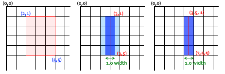
Если вы рассмотрите путь от (3, 1) до (3, 5) с толщиной строки 1.0, вы получите ситуацию во втором изображении. Фактическая заполняемая область, (синяя), распространяется только наполовину в пикселях по обе стороны пути. Приблизительно это означает, что частично затенённые пиксели приводят к заполнению всей области (светло-голубой и синей) цветом, только наполовину темным, чем фактический цвет штриха. Это то, что происходит с линией шириной 1.0 в предыдущем примере кода.
Чтобы исправить это, вы должны быть более точными при создании пути. Зная, что линия шириной 1.0 занимает половину единицы по обе стороны пути, создание пути от (3.5, 1) до (3.5, 5) приведёт к ситуации в третьем изображении — ширина линии 1.0 закончится верно, точно заполняя вертикальную линию с одним пикселем.
Примечание: Имейте в виду, что в нашем примере с вертикальной линией позиция Y по-прежнему ссылается на целочисленную позицию сетки — иначе мы увидели бы пиксели с половинным охватом в конечных точках (также обратите внимание, что это поведение зависит от текущего стиля lineCap, значение по умолчанию — butt; вы можете вычислить согласованные штрихи с полупиксельными координатами для линий с нечётной шириной, установив стиль lineCap в square, чтобы внешняя граница вокруг конечной точки линии автоматически расширялась, охватывая весь пиксель в точку).
Также обратите внимание, что затронуты только начальные и конечные точки пути: если путь закрыт с помощью closePath(), — нет начальной и конечной точки; вместо этого все конечные точки в пути подключены к их прикреплённому предыдущему и следующему сегментам и при текущей настройке стиля lineJoin в значении по умолчанию — miter, с эффектом автоматического расширения внешних границ подключённых сегментов до их точки пересечения — обработанный ход будет точно покрывать полные пиксели с центром в каждой конечной точке, если эти связанные сегменты горизонтальны и/или вертикальны). См. следующие два раздела, демонстрирующие эти дополнительные стили.
Для линий с чётной шириной каждая половина заканчивается как целое количество пикселей, поэтому вам нужен путь, который находится между пикселями (то есть (3,1) — (3,5)), вместо середины пикселей.
Хотя это и необычно, когда изначально работаешь с масштабируемой 2D-графикой, обращая внимание на сетку пикселей и положение путей, но вы убедитесь, что ваши рисунки будут выглядеть правильно, независимо от масштабирования или любых других преобразований. Вертикальная линия ширины 1,0, построенная таким образом, станет чёткой 2-пиксельной линией при увеличении на 2 и появится в правильном положении.
Пример lineCap
Свойство lineCap определяет, как выводятся конечные точки каждой строки. Для этого свойства есть три возможных значения: butt, round и square. По умолчанию для этого свойства установлено значение butt.

butt-
Концы линий соответствуют крайним точкам.
round-
Концы линий округлены.
square-
Концы линий описаны квадратом с равной шириной и половиной высоты толщины линии.
В этом примере мы проведём три строки, каждая из которых имеет другое значение для свойства lineCap. Я также добавил два руководства, чтобы увидеть точные различия между ними. Каждая из этих линий начинается и заканчивается именно на этих направляющих.
Строка слева использует butt опцию по умолчанию. Вы заметите, что она полностью очищена от направляющих. Второй вариант — round опция. Это добавляет полукруг к концу, который имеет радиус, равный половине ширины линии. Строка справа использует square опцию. Это добавляет поле с равной шириной и половиной высоты толщины линии.
function draw() {
  var ctx = document.getElementById('canvas').getContext('2d');
  var lineCap = ['butt','round','square'];

  // Draw guides
  ctx.strokeStyle = '#09f';
  ctx.beginPath();
  ctx.moveTo(10,10);
  ctx.lineTo(140,10);
  ctx.moveTo(10,140);
  ctx.lineTo(140,140);
  ctx.stroke();

  // Draw lines
  ctx.strokeStyle = 'black';
  for (var i=0;i<lineCap.length;i++){
    ctx.lineWidth = 15;
    ctx.lineCap = lineCap[i];
    ctx.beginPath();
    ctx.moveTo(25+i*50,10);
    ctx.lineTo(25+i*50,140);
    ctx.stroke();
  }
}
<canvas id="canvas" width="150" height="150"></canvas>
| Screenshot | Live sample |
|---|---|
|
Пример lineJoin
Свойство lineJoin определяет, как соединяются два сегмента (линий, дуг или кривых) с ненулевой длиной в форме (вырожденные сегменты с нулевой длиной, заданные конечные точки и контрольные точки находятся точно в том же положении — пропущены).
Для этого свойства есть три возможных значения: round, bevel и miter. По умолчанию для этого свойства установлено значение miter. Обратите внимание, что настройка lineJoin не действует, если два связанных сегмента имеют одно и то же направление, потому что в этом случае не будет добавлена область соединения.

round-
Радиус заполняемой части для скруглённых углов равен половине ширины линии. центр этого радиуса совпадает с концами подключённых сегментов.
bevel-
Заполняет дополнительную треугольную область между общей конечной точкой подключённых сегментов и отдельными внешними прямоугольными углами каждого сегмента.
miter-
Подключённые сегменты соединяются путём расширения их внешних краёв для соединения в одной точке с эффектом заполнения дополнительной области в форме пастилки. Эта настройка выполняется с помощью свойства
miterLimit, которое объясняется ниже.
В приведённом ниже примере показаны три разных пути, демонстрирующие каждый из этих трёх свойств lineJoin; результат — выше.
function draw() {
  var ctx = document.getElementById('canvas').getContext('2d');
  var lineJoin = ['round','bevel','miter'];
  ctx.lineWidth = 10;
  for (var i=0;i<lineJoin.length;i++){
    ctx.lineJoin = lineJoin[i];
    ctx.beginPath();
    ctx.moveTo(-5,5+i*40);
    ctx.lineTo(35,45+i*40);
    ctx.lineTo(75,5+i*40);
    ctx.lineTo(115,45+i*40);
    ctx.lineTo(155,5+i*40);
    ctx.stroke();
  }
}
<canvas id="canvas" width="150" height="150"></canvas>
| Screenshot | Live sample |
|---|---|
|
Демонстрация свойства miterLimit
Как вы видели в предыдущем примере, при объединении двух строк с опцией miter внешние края двух соединительных линий расширены до точки, где они встречаются. Для линий, которые находятся под большими углами друг с другом, эта точка находится недалеко от внутренней точки соединения. Однако, поскольку углы между каждой линией уменьшаются, расстояние (длина меча) между этими точками увеличивается экспоненциально.
Свойство miterLimit определяет, как далеко можно установить внешнюю точку соединения из внутренней точки подключения. Если две линии превышают это значение, вместо этого получается привязка конуса. Обратите внимание, что максимальная длина митра является произведением ширины линии, измеренной в текущей системе координат, значением этого свойства miterLimit (значение по умолчанию 10,0 в HTML <canvas>), поэтому miterLimit может устанавливаться независимо от текущей шкалы дисплея или любых аффинных преобразований путей: она влияет только на эффективно визуализированную форму рёбер линии.
Точнее, предел митры является максимально допустимым отношением длины расширения (в холсте HTML он измеряется между внешним углом соединённых краёв линии и общей конечной точкой соединительных сегментов, указанными на пути), до половины ширины линии. Его можно равнозначно определить как максимально допустимое отношение расстояния между внутренней и внешней точками перехода краёв к общей ширине линии. Затем он равен косекансу с половиной минимального внутреннего угла соединительных сегментов, ниже которого не будет создано ни одного соединения митра, а только скос соединяется:
miterLimit= maxmiterLength/lineWidth= 1 / sin ( min θ / 2 )- Предел митры по умолчанию, равный 10,0, разделит все митры углов, острее примерно 11 градусов.
- Предел митры, равный √2 ≈ 1.4142136 (rounded up) сгладит миты для всех острых углов, поддерживая митры только для тупых или прямых углов.
- Предел митры, равный 1,0, действителен, но отключит все миты.
- Значения ниже 1.0 являются недопустимыми для предела митры.
Вот небольшая демонстрация, в которой вы можете динамически установить miterLimit и посмотреть, как это влияет на фигуры на холсте. Синие линии показывают, где начальная и конечная точки для каждой из линий в шаблоне зигзага.
Если вы укажете в этой демонстрации значение miterLimit ниже 4.2, ни один из видимых углов не присоединится к расширению митры, но только с небольшим скосом рядом с синими линиями; с отметкой miterLimit выше 10, большинство углов в этой демонстрации должны соединяться с митрой, удалённой от синих линий, высота которой уменьшается между углами слева направо, потому что они соединяются с растущими углами; с промежуточными значениями углы с левой стороны будут соединяться только с скосом рядом с синими линиями, а углы с правой стороны с удлинителем митры (также с уменьшающейся высотой).
function draw() {
  var ctx = document.getElementById('canvas').getContext('2d');

  // Clear canvas
  ctx.clearRect(0,0,150,150);

  // Draw guides
  ctx.strokeStyle = '#09f';
  ctx.lineWidth   = 2;
  ctx.strokeRect(-5,50,160,50);

  // Set line styles
  ctx.strokeStyle = '#000';
  ctx.lineWidth = 10;

  // check input
  if (document.getElementById('miterLimit').value.match(/d+(.d+)?/)) {
    ctx.miterLimit = parseFloat(document.getElementById('miterLimit').value);
  } else {
    alert('Value must be a positive number');
  }

  // Draw lines
  ctx.beginPath();
  ctx.moveTo(0,100);
  for (i=0;i<24;i++){
    var dy = i%2==0 ? 25 : -25 ;
    ctx.lineTo(Math.pow(i,1.5)*2,75+dy);
  }
  ctx.stroke();
  return false;
}
<table>
  <tr>
    <td><canvas id="canvas" width="150" height="150"></canvas></td>
    <td>Change the <code>miterLimit</code> by entering a new value below and clicking the redraw button.<br><br>
      <form onsubmit="return draw();">
        <label>Miter limit</label>
        <input type="text" size="3" id="miterLimit"/>
        <input type="submit" value="Redraw"/>
      </form>
    </td>
  </tr>
</table>
document.getElementById('miterLimit').value = document.getElementById('canvas').getContext('2d').miterLimit;
draw();
| Screenshot | Live sample |
|---|---|
 |
Использование штрихов
Метод setLineDash и свойство lineDashOffset задают шаблон штрихов для линий. Метод setLineDash принимает список чисел, который определяет расстояния для попеременного рисования линии и разрыва, а свойство lineDashOffset устанавливает смещение, с которого начинается шаблон.
В этом примере мы создаём эффект походных муравьёв. Это техника анимации, часто встречающаяся в инструментах выбора программ компьютерной графики. Это помогает пользователю отличить границу выделения от фона изображения, анимируя границу. В следующей части этого руководства вы узнаете, как сделать эту и другие основные анимации.
<canvas id="canvas" width="110" height="110"></canvas>
var ctx = document.getElementById('canvas').getContext('2d');
var offset = 0;

function draw() {
  ctx.clearRect(0,0, canvas.width, canvas.height);
  ctx.setLineDash([4, 2]);
  ctx.lineDashOffset = -offset;
  ctx.strokeRect(10,10, 100, 100);
}

function march() {
  offset++;
  if (offset > 16) {
    offset = 0;
  }
  draw();
  setTimeout(march, 20);
}

march();
| Screenshot | Live sample |
|---|---|
 |
Градиенты
Just like any normal drawing program, we can fill and stroke shapes using linear and radial gradients. We create a CanvasGradient object by using one of the following methods. We can then assign this object to the fillStyle or strokeStyle properties.
createLinearGradient(x1, y1, x2, y2)-
Creates a linear gradient object with a starting point of (
x1,y1) and an end point of (x2,y2). createRadialGradient(x1, y1, r1, x2, y2, r2)(en-US)-
Creates a radial gradient. The parameters represent two circles, one with its center at (
x1,y1) and a radius ofr1, and the other with its center at (x2,y2) with a radius ofr2.
For example:
var lineargradient = ctx.createLinearGradient(0, 0, 150, 150);
var radialgradient = ctx.createRadialGradient(75, 75, 0, 75, 75, 100);
Once we’ve created a CanvasGradient object we can assign colors to it by using the addColorStop() method.
gradient.addColorStop(position, color)(en-US)-
Creates a new color stop on the
gradientobject. Thepositionis a number between 0.0 and 1.0 and defines the relative position of the color in the gradient, and thecolorargument must be a string representing a CSS<color>, indicating the color the gradient should reach at that offset into the transition.
You can add as many color stops to a gradient as you need. Below is a very simple linear gradient from white to black.
var lineargradient = ctx.createLinearGradient(0,0,150,150);
lineargradient.addColorStop(0, 'white');
lineargradient.addColorStop(1, 'black');
Пример createLinearGradient
In this example, we’ll create two different gradients. As you can see here, both the strokeStyle and fillStyle properties can accept a canvasGradient object as valid input.
function draw() {
  var ctx = document.getElementById('canvas').getContext('2d');

  // Create gradients
  var lingrad = ctx.createLinearGradient(0,0,0,150);
  lingrad.addColorStop(0, '#00ABEB');
  lingrad.addColorStop(0.5, '#fff');
  lingrad.addColorStop(0.5, '#26C000');
  lingrad.addColorStop(1, '#fff');

  var lingrad2 = ctx.createLinearGradient(0,50,0,95);
  lingrad2.addColorStop(0.5, '#000');
  lingrad2.addColorStop(1, 'rgba(0,0,0,0)');

  // assign gradients to fill and stroke styles
  ctx.fillStyle = lingrad;
  ctx.strokeStyle = lingrad2;

  // draw shapes
  ctx.fillRect(10,10,130,130);
  ctx.strokeRect(50,50,50,50);

}
<canvas id="canvas" width="150" height="150"></canvas>
The first is a background gradient. As you can see, we assigned two colors at the same position. You do this to make very sharp color transitions—in this case from white to green. Normally, it doesn’t matter in what order you define the color stops, but in this special case, it does significantly. If you keep the assignments in the order you want them to appear, this won’t be a problem.
In the second gradient, we didn’t assign the starting color (at position 0.0) since it wasn’t strictly necessary, because it will automatically assume the color of the next color stop. Therefore, assigning the black color at position 0.5 automatically makes the gradient, from the start to this stop, black.
| Screenshot | Live sample |
|---|---|
 |
Пример createRadialGradient
In this example, we’ll define four different radial gradients. Because we have control over the start and closing points of the gradient, we can achieve more complex effects than we would normally have in the «classic» radial gradients we see in, for instance, Photoshop (that is, a gradient with a single center point where the gradient expands outward in a circular shape).
function draw() {
  var ctx = document.getElementById('canvas').getContext('2d');

  // Create gradients
  var radgrad = ctx.createRadialGradient(45,45,10,52,50,30);
  radgrad.addColorStop(0, '#A7D30C');
  radgrad.addColorStop(0.9, '#019F62');
  radgrad.addColorStop(1, 'rgba(1,159,98,0)');

  var radgrad2 = ctx.createRadialGradient(105,105,20,112,120,50);
  radgrad2.addColorStop(0, '#FF5F98');
  radgrad2.addColorStop(0.75, '#FF0188');
  radgrad2.addColorStop(1, 'rgba(255,1,136,0)');

  var radgrad3 = ctx.createRadialGradient(95,15,15,102,20,40);
  radgrad3.addColorStop(0, '#00C9FF');
  radgrad3.addColorStop(0.8, '#00B5E2');
  radgrad3.addColorStop(1, 'rgba(0,201,255,0)');

  var radgrad4 = ctx.createRadialGradient(0,150,50,0,140,90);
  radgrad4.addColorStop(0, '#F4F201');
  radgrad4.addColorStop(0.8, '#E4C700');
  radgrad4.addColorStop(1, 'rgba(228,199,0,0)');

  // draw shapes
  ctx.fillStyle = radgrad4;
  ctx.fillRect(0,0,150,150);
  ctx.fillStyle = radgrad3;
  ctx.fillRect(0,0,150,150);
  ctx.fillStyle = radgrad2;
  ctx.fillRect(0,0,150,150);
  ctx.fillStyle = radgrad;
  ctx.fillRect(0,0,150,150);
}
<canvas id="canvas" width="150" height="150"></canvas>
In this case, we’ve offset the starting point slightly from the end point to achieve a spherical 3D effect. It’s best to try to avoid letting the inside and outside circles overlap because this results in strange effects which are hard to predict.
The last color stop in each of the four gradients uses a fully transparent color. If you want to have a nice transition from this to the previous color stop, both colors should be equal. This isn’t very obvious from the code because it uses two different CSS color methods as a demonstration, but in the first gradient #019F62 = rgba(1,159,98,1).
| Screenshot | Live sample |
|---|---|
 |
Шаблоны
В одном из предыдущих примеров мы использовали несколько циклов, чтобы создать шаблон из повторяющихся изображений. Однако, есть более простой способ сделать подобное — метод createPattern().
createPattern(image, type)(en-US)-
Создаёт и возвращает новый canvas объект — шаблон (pattern).
image—CanvasImageSource(en-US) (то естьHTMLImageElement, другой холст, элемент<video>или подобный объект.type— строка, указывающая, как использоватьimage.
Тип указывает, как использовать image для создания шаблона и должен быть одним из следующих значений:
repeat-
Повторяет изображение в вертикальном и горизонтальном направлениях.
repeat-x-
Повторяет изображение по горизонтали, но не по вертикали.
repeat-y-
Повторяет изображение по вертикали, но не по горизонтали.
no-repeat-
Не повторяет изображение. Используется только один раз.
Мы используем этот метод, чтобы создать CanvasPattern объект, который очень похож на методы градиента, рассмотренные ранее. Как только мы создали шаблон, мы можем назначить ему свойства fillStyle или strokeStyle. Например:
var img = new Image();
img.src = 'someimage.png';
var ptrn = ctx.createPattern(img,'repeat');
Примечание: По аналогии с методом drawImage(), вы должны убедиться, что изображение, которое вы используете, загружено до вызова этого метода. Иначе шаблон может быть отрисован некорректно.
Пример createPattern
In this last example, we’ll create a pattern to assign to the fillStyle property. The only thing worth noting is the use of the image’s onload handler. This is to make sure the image is loaded before it is assigned to the pattern.
function draw() {
  var ctx = document.getElementById('canvas').getContext('2d');

  // create new image object to use as pattern
  var img = new Image();
  img.src = 'canvas_createpattern.png';
  img.onload = function(){

    // create pattern
    var ptrn = ctx.createPattern(img,'repeat');
    ctx.fillStyle = ptrn;
    ctx.fillRect(0,0,150,150);

  }
}
<canvas id="canvas" width="150" height="150"></canvas>
| Screenshot | Live sample |
|---|---|
 |
Тени
Using shadows involves just four properties:
shadowOffsetX = float(en-US)-
Indicates the horizontal distance the shadow should extend from the object. This value isn’t affected by the transformation matrix. The default is 0.
shadowOffsetY = float(en-US)-
Indicates the vertical distance the shadow should extend from the object. This value isn’t affected by the transformation matrix. The default is 0.
shadowBlur = float(en-US)-
Indicates the size of the blurring effect; this value doesn’t correspond to a number of pixels and is not affected by the current transformation matrix. The default value is 0.
shadowColor = color(en-US)-
A standard CSS color value indicating the color of the shadow effect; by default, it is fully-transparent black.
The properties shadowOffsetX and shadowOffsetY indicate how far the shadow should extend from the object in the X and Y directions; these values aren’t affected by the current transformation matrix. Use negative values to cause the shadow to extend up or to the left, and positive values to cause the shadow to extend down or to the right. These are both 0 by default.
The shadowBlur property indicates the size of the blurring effect; this value doesn’t correspond to a number of pixels and is not affected by the current transformation matrix. The default value is 0.
The shadowColor property is a standard CSS color value indicating the color of the shadow effect; by default, it is fully-transparent black.
Пример текста с тенью
This example draws a text string with a shadowing effect.
function draw() {
  var ctx = document.getElementById('canvas').getContext('2d');

  ctx.shadowOffsetX = 2;
  ctx.shadowOffsetY = 2;
  ctx.shadowBlur = 2;
  ctx.shadowColor = "rgba(0, 0, 0, 0.5)";

  ctx.font = "20px Times New Roman";
  ctx.fillStyle = "Black";
  ctx.fillText("Sample String", 5, 30);
}
<canvas id="canvas" width="150" height="80"></canvas>
| Screenshot | Live sample |
|---|---|
 |
We will look at the font property and fillText method in the next chapter about drawing text.
Canvas fill rules
When using fill (or clip (en-US) and isPointinPath (en-US)) you can optionally provide a fill rule algorithm by which to determine if a point is inside or outside a path and thus if it gets filled or not. This is useful when a path intersetcs itself or is nested.
Two values are possible:
nonzero-
The non-zero winding rule, which is the default rule.
evenodd-
The even-odd winding rule.
In this example we are using the evenodd rule.
function draw() {
  var ctx = document.getElementById('canvas').getContext('2d');
  ctx.beginPath();
  ctx.arc(50, 50, 30, 0, Math.PI*2, true);
  ctx.arc(50, 50, 15, 0, Math.PI*2, true);
  ctx.fill("evenodd");
}
<canvas id="canvas" width="100" height="100"></canvas>
| Screenshot | Live sample |
|---|---|
 |
- « Предыдущая статья
- Следующая статья »
Vue.js has this amazing power to manipulate the attributes of an SVG file directly without any aid. While other flux-based frameworks often require support of external libraries, Vue doesn’t. In this example, I’ll show you how you can manipulate the “fill” attribute of SVG files with the native color picker of your web browser. For that, here’s the code I’ve written:
Code language: HTML, XML (xml)
<template> <div id="app"> <div class="np-icons"> <div class="np-icon-ib"> <FacebookIcon :svgColor="facebookColor" /> </div> <div class="np-icon-ib"> <TwitterIcon :svgColor="twitterColor" /> </div> <div class="np-icon-ib"> <InstagramIcon :svgColor="instagramColor" /> </div> <div class="np-icon-ib"> <BehanceIcon :svgColor="behanceColor" /> </div> </div> <div class="np-icon-color-picker"> <label for="favcolor">Select facebook color</label> <input v-model="facebookColor" type="color" id="favcolor" name="favcolor" value="#4267B2" class="np-input-color-pos" /> </div> <div class="np-icon-color-picker"> <label for="favcolor">Select twitter color</label> <input v-model="twitterColor" type="color" id="favcolor" name="favcolor" value="#1DA1F2" class="np-input-color-pos" /> </div> <div class="np-icon-color-picker"> <label for="favcolor">Select instagram color</label> <input v-model="instagramColor" type="color" id="favcolor" name="favcolor" value="#f000ff" class="np-input-color-pos" /> </div> <div class="np-icon-color-picker"> <label for="favcolor">Select behance color</label> <input v-model="behanceColor" type="color" id="favcolor" name="favcolor" value="#053eff" class="np-input-color-pos" /> </div> <div class="np-credits">www.nightprogrammer.com</div> </div> </template> <script> import FacebookIcon from "./../assets/facebook"; import TwitterIcon from "./../assets/twitter"; import InstagramIcon from "./../assets/instagram"; import BehanceIcon from "./../assets/behance"; export default { name: "App", data() { return { facebookColor: "#4267B2", twitterColor: "#1DA1F2", instagramColor: "#f000ff", behanceColor: "#053eff", }; }, components: { FacebookIcon, TwitterIcon, InstagramIcon, BehanceIcon, }, }; </script> <style> #app { font-family: "Avenir", Helvetica, Arial, sans-serif; -webkit-font-smoothing: antialiased; -moz-osx-font-smoothing: grayscale; } .np-icons { padding-bottom: 12px; } .np-icon-ib { display: inline-block; padding-right: 12px; } .np-credits { font-size: 12px; padding-top: 14px; } .np-icon-color-picker { padding-bottom: 6px; } .np-input-color-pos { margin-left: 10px; } </style>
As shown in the code above, I’ve imported four SVG files as components and used them on lines 5, 8, 11, and 14 respectively. I’ve passed a prop name svgColor to each of them.
I’ve controlled their values using the local states declared through 74 to 77. You can directly manipulate the HEX values using the native color input picker. I’ve done so on line 19, as in case of Facebook. Now if you open any of the SVG components, here’s how they look like. This is for Facebook:
Code language: HTML, XML (xml)
<template> <div> <svg :fill="svgColor" version="1.1" baseProfile="tiny" id="Layer_1" xmlns:x="&ns_extend;" xmlns:i="&ns_ai;" xmlns:graph="&ns_graphs;" xmlns="http://www.w3.org/2000/svg" xmlns:xlink="http://www.w3.org/1999/xlink" xmlns:a="http://ns.adobe.com/AdobeSVGViewerExtensions/3.0/" x="0px" y="0px" width="42px" height="42px" viewBox="-0.5 0.5 42 42" xml:space="preserve" > <path d="M28.08,6.51c0.29-0.01,1.109-0.03,1.42-0.01c1.12,0,2.84-0.1,4,0v5h-4c-1.46,0-2,0.35-2,2v4h5v5h-5v14h-5v-14h-4v-5h4 l-0.061-4.42c0-3.061,0.621-4.92,3.15-6.02C26.24,6.78,27.23,6.53,28.08,6.51z M0.5,1.5v39h39v-39H0.5z" /> </svg> </div> </template> <script> export default { name: "Facebook", props: ["svgColor"], }; </script>
I’ve used an attribute called fill on line 4. It receives its value as a prop svgColor as shown on line 32. You’d notice that this template doesn’t contain any logic code. All it does is, renders the component based on the color change received in the svgColor prop.
You can find a working version of the above example from my repos here:
Codesandbox/Demo | Github
Attributes
attr() as setter
returns itselfanimate yes (only for numbers, arrays, colors, ...)
Set a single attribute:
rect.attr('x', 50)Set multiple attributes at once:
rect.attr({
  fill: '#f06'
, 'fill-opacity': 0.5
, stroke: '#000'
, 'stroke-width': 10
})
Set an attribute with a namespace:
rect.attr('x', 50, 'http://www.w3.org/2000/svg')Explicitly remove an attribute:
rect.attr('fill', null)attr() as getter
returns value (string, number, ...)
You can get and set an element’s attributes directly using attr().
Get a single attribute:
var x = rect.attr('x')Get all attributes as an object:
var attributes = rect.attr()Positioning
While positioning an element by directly setting its attributes works only if the attributes are used natively by that type of element, the positioning methods described below are much more convenient as they work for all element types.
For example, the following code works because each element is positioned by setting native attributes:
rect.attr({ x: 20, y: 60 })
circle.attr({ cx: 50, cy: 40 })
The rect will be moved by its upper left corner to the new coordinates, and the circle will be moved by its centre. However, trying to move a circle by its ‘corner’ or a rect by its centre in this way will fail. The following lines will get silently ignored as the attributes that are addressed are not natively used by the element setting them:
rect.attr({ cx: 20, cy: 60 })
circle.attr({ x: 50, y: 40 })
However, the positioning methods detailed below will work for all element types, regardless of whether the attributes being addressed are native to the type. So, unlike the lines above, these lines work just fine:
rect.cx(20).cy(60)
circle.x(50).y(40)
It is important to note, though, that these methods are only intended for use with user (unitless) coordinates. If for example, an element has its size set via percentages or other units, the positioning methods that address its native attributes will most likely still work, but the ones that address non-native attributes will give unexpected results — as both getters and setters!
move()
returns itselfanimate yes
Move the element by its upper left corner to a given x and y position:
rect.move(200, 350)x() as setter
returns itselfanimate yes
Move the element by its upper left corner along the x-axis only:
rect.x(200)x() as getter
returns value
Without an argument the x() method serves as a getter:
var x = rect.x()y() as setter
returns itselfanimate yes
Move the element by its upper left corner along the y-axis only:
rect.y(350)y() as getter
returns value
Without an argument the y() method serves as a getter:
var y = rect.y()center()
returns itselfanimate yes
Move the element by its center to a given cx and cy position:
rect.center(150, 150)cx() as setter
returns itselfanimate yes
Move the element by its centre in the x direction only:
rect.cx(200)cx() as getter
returns value
Without an argument the cx() method serves as a getter:
var cx = rect.cx()cy() as setter
returns itselfanimate yes
Move the element by its centre in the y direction only:
rect.cy(350)cy() as getter
returns value
Without an argument the cy() method serves as a getter as well:
var cy = rect.cy()dmove()
returns itselfanimate yes
Shift the element in both the x and y directions relative to its current position:
rect.dmove(10, 30)Note: when using dmove() (and dx() or dy() too for that matter), always make sure you provide values of the same unit the element is originally positioned in. So if the element is at x:10%, use element.dx('5%') and not element.dx('5px').
dx()
returns itselfanimate yes
Shift the element in the x direction relative to its current position:
rect.dx(200)dy()
returns itselfanimate yes
Shift the element in the y direction relative to its current position:
rect.dy(200)Resizing
size()
returns itselfanimate yes
Set the size of an element to a given width and height:
rect.size(200, 300)Proportional resizing is also possible by leaving out height:
rect.size(200)Or by passing null as the value for width:
rect.size(null, 200)As with positioning, the size of an element could be set by using attr(). But because every type of element is handles its size differently the size() method is much more convenient.
There is one exception though: for SVG.Text elements, this method takes only one argument and applies the given value to the font-size attribute.
width() as setter
returns itselfanimate yes
Set the width of an element:
rect.width(200)width() as getter
returns value
var width = rect.width()height() as setter
returns itselfanimate yes
Set the height of an element:
rect.height(325)height() as getter
returns value
rect.height()radius()
returns itselfanimate yes
Circles, ellipses, and rects may use the radius() method. On rects, it defines rounded corners.
For a circle, the argument sets the r attribute.
circle.radius(10)For ellipses and rects, pass two arguments to set the rx and ry attributes individually. Or, pass a single argument, to make the two attributes equal.
ellipse.radius(10, 20)
rect.radius(5)
Syntactic sugar
fill()
returns itself
The fill() method is a pretty alternative to the attr() method:
rect.fill({ color: '#f06', opacity: 0.6 })A single hex string will work as well:
rect.fill('#f06')Last but not least, you can also use an image as fill, simply by passing an image url:
rect.fill('images/shade.jpg')Or if you want more control over the size of the image, you can pass an image instance as well:
rect.fill(draw.image('images/shade.jpg', 20, 20))stroke()
returns itself
The stroke() method is similar to fill():
rect.stroke({ color: '#f06', opacity: 0.6, width: 5 })Like fill, a single hex string will work as well:
rect.stroke('#f06')Not unlike the fill() method, you can also use an image as stroke, simply by passing an image url:
rect.stroke('images/shade.jpg')Or if you want more control over the size of the image, you can pass an image instance as well:
rect.stroke(draw.image('images/shade.jpg', 20, 20))opacity()
returns itself
To set the overall opacity of an element:
rect.opacity(0.5)Transforming
transform() as setter
returns itselfanimate yes
As a setter it has two ways of working. By default transformations are absolute. For example, if you call:
element.transform({ rotation: 125 }).transform({ rotation: 37.5 })The resulting rotation will be 37.5 and not the sum of the two transformations. But if that’s what you want there is a way out by adding the relative parameter. That would be:
element.transform({ rotation: 125 }).transform({ rotation: 37.5, relative: true })Alternatively a relative flag can be passed as the second argument:
element.transform({ rotation: 125 }).transform({ rotation: 37.5 }, true)Available transformations are:
rotationwith optionalcxandcyscalewith optionalcxandcyscaleXwith optionalcxandcyscaleYwith optionalcxandcyskewXwith optionalcxandcyskewYwith optionalcxandcyxya,b,c,d,eand/orfor an existing matrix instead of the object
transform() as getter
returns value
The transform() method acts as a full getter without an argument:
element.transform()The returned object contains the following values:
x(translation on the x-axis)y(translation on the y-axis)skewX(calculated skew on x-axis)skewY(calculated skew on y-axis)scaleX(calculated scale on x-axis)scaleY(calculated scale on y-axis)rotation(calculated rotation)cx(last used rotation centre on x-axis)cy(last used rotation centre on y-axis)
Additionally a string value for the required property can be passed:
element.transform('rotation')flip()
returns itselfanimate yes
Flips element over a given axis:
element.flip('x')or
element.flip('y')By default, elements are flipped over their centre point. The flip axis position can be defined with the second argument:
element.flip('x', 150)or
element.flip('y', 100)Finally, an element can also be flipped over two axes at once by not providing an axis value:
element.flip()And flipping on both axes at the same offset can be done by passing only a numeric value:
element.flip(5)rotate()
returns itselfanimate yes
The rotate() method will automatically rotate elements according to the center of the element:
// rotate(degrees)
element.rotate(45)
Although you can also define a specific rotation point:
// rotate(degrees, cx, cy)
element.rotate(45, 50, 50)
skew()
returns itselfanimate yes
The skew() method will take an x and y value:
// skew(x, y)
element.skew(0, 45)
scale()
returns itselfanimate yes
The scale() method will scale elements by multiplying their x and y
coordinates by either a single scale factor or two separate scale factors:
// scale(factor)
element.scale(2)
// scale(xFactor, yFactor)
element.scale(0.5, -1)
By default, scaling is relative to the center of the element.
You can also define a specific center point (vanishing point of scaling):
// scale(factor, centerX, centerY)
element.scale(2, 0, 0)
// scale(xFactor, yFactor, centerX, centerY)
element.scale(0.5, -1, 0, 0)
translate()
returns itselfanimate yes
The translate() method will take an x and y value:
// translate(x, y)
element.translate(0.5, -1)
Styles
style() as setter
returns itself
With the style() method the style attribute can be managed like attributes with attr:
element.style('cursor', 'pointer')Multiple styles can be set at once using an object:
element.style({ cursor: 'pointer', fill: '#f03' })Or a css string:
element.style('cursor:pointer;fill:#f03;')Explicitly deleting individual style definitions works the same as with the attr() method:
element.style('cursor', null)style() as getter
returns value (string, number, …)
Similar to attr() the style() method can also act as a getter:
element.style('cursor')
// => pointer
Or even a full getter:
element.style()
// => 'cursor:pointer;fill:#f03;'
hide()
returns itself
Hide element:
element.hide()show()
returns itself
Show (unhide) element:
element.show()visible()
returns boolean
To check if the element is visible:
element.visible()Class Names
addClass()
returns itself
Adds a given css class:
element.addClass('pink-flower')classes()
returns array
Fetches the CSS classes for the node as an array:
element.classes()hasClass()
returns boolean
Test the presence of a given css class:
element.hasClass('purple-rain')removeClass()
returns itself
Removes a given css class:
element.removeClass('pink-flower')toggleClass()
returns itself
Toggles a given css class:
element.toggleClass('pink-flower')Data
The data() method allows you to bind arbitrary objects, strings and numbers to SVG elements.
data() as getter
returns value
Fetching the values is similar to the attr() method:
var key = rect.data('key')data() as setter
returns itself
rect.data('key', { value: { data: 0.3 }})Or set multiple values at once:
rect.data({
  forbidden: 'fruit'
, multiple: {
    values: 'in'
  , an: 'object'
  }
})
Removing the data altogether:
rect.data('key', null)Your values will always be stored as JSON and in some cases this might not be desirable. If you want to store the value as-is, just pass true as the third argument:
rect.data('key', 'value', true)Memory
remember() as getter
returns value
To retrieve a memory
rect.remember('oldBBox')remember() as setter
returns itself
Storing data in-memory is very much like setting attributes:
rect.remember('oldBBox', rect.bbox())Multiple values can also be remembered at once:
rect.remember({
  oldFill:    rect.attr('fill')
, oldStroke:  rect.attr('stroke')
})
forget()
returns itself
Erasing a single memory:
rect.forget('oldBBox')Or erasing multiple memories at once:
rect.forget('oldFill', 'oldStroke')And finally, just erasing the whole memory:
rect.forget()Document Tree
add()
returns itself
Sets the calling element as the parent node of the argument. Returns the parent:
var rect = draw.rect(100, 100)
var group = draw.group()

group.add(rect) //-> returns group
addTo()
returns itself
Sets the calling element as a child node of the argument. Returns the child:
rect.addTo(group) //-> returns rectclone()
returns SVG.Element
To make an exact copy of an element the clone() method comes in handy:
var clone = rect.clone()This will create a new, unlinked copy. For making a linked clone, see the use element.
By default, the cloned element is placed directly after the original element.
When you pass a parent parameter to the clone() function it will append the cloned element to the given parent.
put()
returns SVG.Element
Sets the calling element as the parent node of the argument. Returns the child:
group.put(rect) //-> returns rectputIn()
returns SVG.Element
Sets the calling element as a child node of the argument. Returns the parent:
rect.putIn(group) //-> returns groupremove()
returns itself
Removes the calling element from the svg document:
rect.remove()replace()
returns SVG.Element
At the calling element’s position in the svg document, replace the calling element with the element passed to the method.
rect.replace(draw.circle(100))toDoc()
returns itself
Same as toParent() but with the root-node as parent
toParent()
returns itself
Moves an element to a different parent (similar to addTo), but without changing its visual representation. All transformations are merged and applied to the element.
rect.toParent(group) // looks the same as beforeungroup() / flatten()
returns itself
Break up a group/container and move all the elements to a given parent node without changing their visual representations. The result is a flat svg structure, e.g. for exporting.
Ungroup all elements in this group recursively and places them into the given parent
group.ungroup(parent, depth)
// (default: parent container of the calling element)
Call it on the whole document to get a flat svg structure:
drawing.ungroup()Break up the group and places all elements in the drawing:
group.ungroup(drawing)Break up all groups until it reaches a depth of 3:
drawing.ungroup(null, 3)Flat and export svg:
var svgString = drawing.ungroup().svg()Arranging
You can arrange elements within their parent SVG document using the following methods.
after()
returns itself
Insert an element after another:
// inserts circle after rect
rect.after(circle)
before()
returns itself
Insert an element before another:
// inserts circle before rect
rect.before(circle)
back()
returns itself
Move element to the back:
rect.back()backward()
returns itself
Move element one step backward:
rect.backward()front()
returns itself
Move element to the front:
rect.front()forward()
returns itself
Move element one step forward:
rect.forward()next()
returns SVG.Element
Get the next sibling:
rect.next()position()
returns number
Get the position (a number) of rect between its siblings:
rect.position()previous()
returns SVG.Element
Get the previous sibling:
rect.previous()siblings()
returns array
The arrange.js module brings some additional methods. To get all siblings of rect, including rect itself:
rect.siblings()Geometry
point()
returns SVG.Point
Transforms a point from screen coordinates to the elements coordinate system.
// e is some mouseevent
var point = path.point(e.screenX, e.screenY) // {x, y}
inside()
returns boolean
To check if a given point is inside the bounding box of an element you can use the inside() method:
var rect = draw.rect(100, 100).move(50, 50)

rect.inside(25, 30) //-> returns false
rect.inside(60, 70) //-> returns trueNote: the x and y positions are tested against the relative position of the element. Any offset on the parent element is not taken into account.