Connecting to the Router
There are two types of routers:
- With default configuration
- Without default configuration. When no specific configuration is found, IP address 192.168.88.1/24 is set on ether1 or combo1, or sfp1.
More information about the current default configuration can be found in the Quick Guide document that came with your device. The quick guide document will include information about which ports should be used to connect for the first time and how to plug in your devices.
This document describes how to set up the device from the ground up, so we will ask you to clear away all defaults.
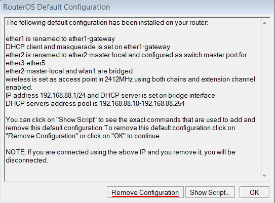
When connecting the first time to the router with the default username admin and no password (for some models, check user password on the sticker), you will be asked to reset or keep the default configuration (even if the default config has only an IP address). Since this article assumes that there is no configuration on the router you should remove it by pressing «r» on the keyboard when prompted or click on the «Remove configuration» button in WinBox.
Router without Default Configuration
If there is no default configuration on the router you have several options, but here we will use one method that suits our needs.
Connect Routers ether1 port to the WAN cable and connect your PC to ether2. Now open WinBox and look for your router in neighbor discovery. See detailed example in Winbox article.
If you see the router in the list, click on MAC address and click Connect.
The simplest way to make sure you have absolutely clean router is to run
/system reset-configuration no-defaults=yes skip-backup=yes
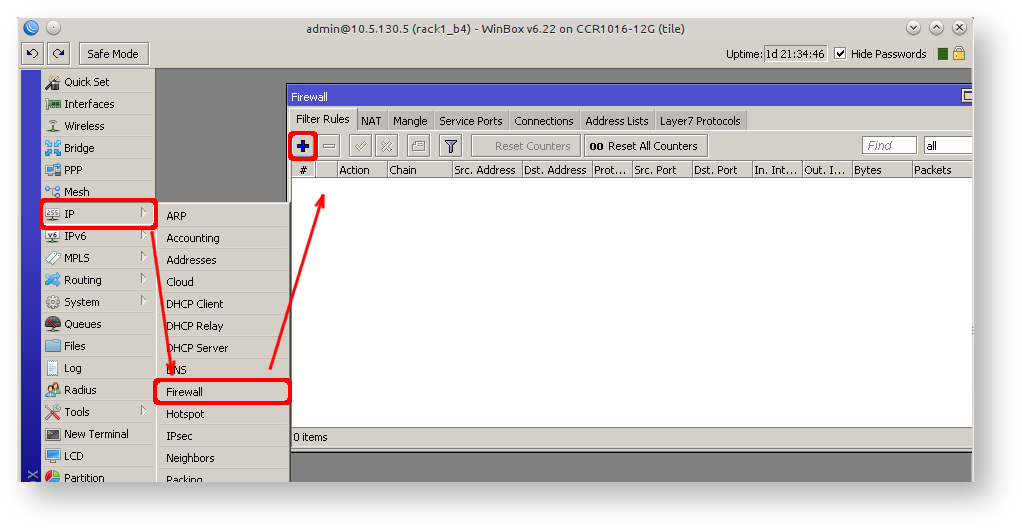
Or from WinBox (Fig. 1-1):

Configuring IP Access
Since MAC connection is not very stable, the first thing we need to do is to set up a router so that IP connectivity is available:
- add bridge interface and bridge ports;
- add an IP address to LAN interface;
- set up a DHCP server.
Set bridge and IP address are quite easy:
/interface bridge add name=local
/interface bridge port add interface=ether2 bridge=local
/ip address add address=192.168.88.1/24 interface=local
If you prefer WinBox/WeBfig as configuration tools:
- Open Bridge window, Bridge tab should be selected;
- Click on the + button, a new dialog will open, enter bridge name local and click on OK;
- Select the Ports tab and click on the + button, a new dialog will open;
- select interface ether2 and bridge local form drop-down lists and click on the OK button to apply settings;
- You may close the bridge dialog.
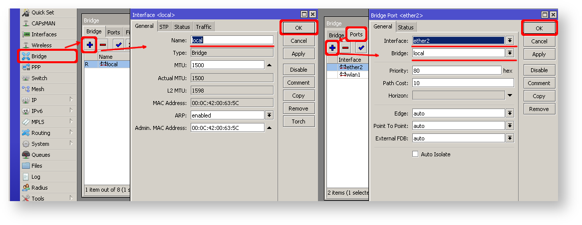
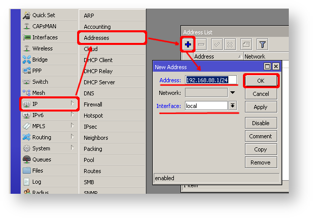
- Open Ip -> Addresses dialog;
- Click on the + button, a new dialog will open;
- Enter IP address 192.168.88.1/24 select interface local from the drop-down list and click on OK button;
The next step is to set up a DHCP server. We will run the setup command for easy and fast configuration:
      [admin@MikroTik] /ip dhcp-server setup [enter]
      Select interface to run DHCP server on

      dhcp server interface: local [enter]
      Select network for DHCP addresses

      dhcp address space: 192.168.88.0/24 [enter]
      Select gateway for given network

      gateway for dhcp network: 192.168.88.1 [enter]
      Select pool of ip addresses given out by DHCP server

      addresses to give out: 192.168.88.2-192.168.88.254 [enter]
      Select DNS servers

      dns servers: 192.168.88.1 [enter]
      Select lease time

      lease time: 10m [enter]
Notice that most of the configuration options are automatically determined and you just simply need to hit the enter key.
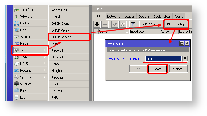
The same setup tool is also available in WinBox/WeBfig:
- Open Ip -> DHCP Server window, DHCP tab should be selected;
- Click on the DHCP Setup button, a new dialog will open, enter DHCP Server Interface local and click on Next button;
- Follow the wizard to complete the setup.
Now connected PC should be able to get a dynamic IP address. Close the Winbox and reconnect to the router using IP address (192.168.88.1)
Configuring Internet Connection
The next step is to get internet access to the router. There can be several types of internet connections, but the most common ones are:
- dynamic public IP address;
- static public IP address;
- PPPoE connection.
Dynamic Public IP
Dynamic address configuration is the simplest one. You just need to set up a DHCP client on the public interface. DHCP client will receive information from an internet service provider (ISP) and set up an IP address, DNS, NTP servers, and default route for you.
/ip dhcp-client add disabled=no interface=ether1
After adding the client you should see the assigned address and status should be bound
[admin@MikroTik] /ip dhcp-client> print
Flags: X - disabled, I - invalid
 #   INTERFACE           USE ADD-DEFAULT-ROUTE STATUS        ADDRESS
 0   ether1               yes yes               bound         1.2.3.100/24
Static Public IP
In the case of static address configuration, your ISP gives you parameters, for example:
- IP: 1.2.3.100/24
- Gateway: 1.2.3.1
- DNS: 8.8.8.8
These are three basic parameters that you need to get the internet connection working
To set this in RouterOS we will manually add an IP address, add a default route with a provided gateway, and set up a DNS server
/ip address add address=1.2.3.100/24 interface=ether1
/ip route add gateway=1.2.3.1
/ip dns set servers=8.8.8.8
PPPoE Connection
PPPoE connection also gives you a dynamic IP address and can configure dynamically DNS and default gateway. Typically service provider (ISP) gives you a username and password for the connection
/interface pppoe-client
  add disabled=no interface=ether1 user=me password=123
    add-default-route=yes use-peer-dns=yes
Winbox/Webfig actions:
- Open PPP window, Interfaces tab should be selected;
- Click on the + button, and choose PPPoE Client from the dropdown list, new dialog will open;
- Select interface ether1 from the dropdown list and click on the OK button to apply settings.
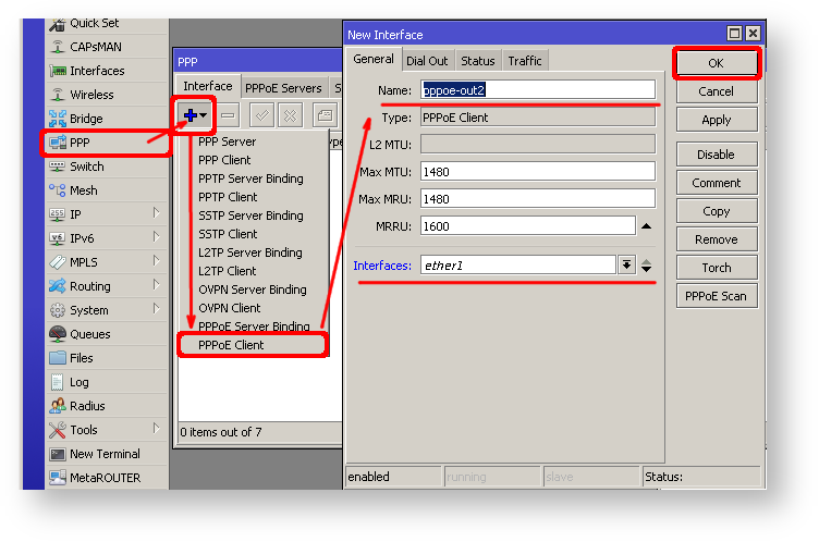
Further in configuration WAN interface is now pppoe-out interface, not ether1.
Verify Connectivity
After successful configuration, you should be able to access the internet from the router.
Verify IP connectivity by pinging known IP address (google DNS server for example)
[admin@MikroTik] > /ping 8.8.8.8
HOST                                     SIZE TTL TIME  STATUS
8.8.8.8                                    56  47 21ms
8.8.8.8                                    56  47 21ms
Verify DNS request
[admin@MikroTik] > /ping www.google.com
HOST                                     SIZE TTL TIME  STATUS
173.194.32.49                              56  55 13ms
173.194.32.49                              56  55 12ms
If everything is set up correctly, ping in both cases should not fail.
In case of failure refer to the troubleshooting section
Protecting the Router
Now anyone over the world can access our router so it is the best time to protect it from intruders and basic attacks
User Password Access
MikroTik routers require password configuration, we suggest using a password generator tool to create secure and non-repeating passwords. With secure password we mean:
- Minimum 12 characters;
- Include numbers, Symbols, Capital and lower case letters;
- Is not a Dictionary Word or Combination of Dictionary Words;
/user set 0 password="!={Ba3N!40TуX+GvKBzjTLIUcx/,"
Another option to set a password,
We strongly suggest using a second method or Winbox interface to apply a new password for your router, just to keep it safe from other unauthorized access.
[admin@MikroTik] > / password
old password:
new password: ******
retype new password: ******
Make sure you remember the password! If you forget it, there is no recovery. You will need to reinstall the router!
You can also add more users with full or limited router access in /user menu
The best practice is to add a new user with a strong password and disable or remove the default admin user.
/user add name=myname password=mypassword group=full
/user remove admin
Note: login to the router with new credentials to check that the username/password is working.
MAC Connectivity Access
By default mac server runs on all interfaces, so we will disable default all entry and add a local interface to disallow MAC connectivity from the WAN port. MAC Telnet Server feature allows you to apply restrictions to the interface «list».
First, create an interface list:
[admin@MikroTik] > /interface list add name=listBridge
Then, add your previously created bridge named «local» to the interface list:
[admin@MikroTik] > /interface list member add list=listBridge interface=local
Apply newly created «list» (of interfaces) to the MAC server:
[admin@MikroTik] > tool mac-server set allowed-interface-list=listBridge
Do the same for Winbox MAC access
[admin@MikroTik] > tool mac-server mac-winbox set allowed-interface-list=listBridge
Winbox/Webfig actions:
- Open Interfaces → Interface List → Lists window and add a new list by clicking «+»;
- Input the interface list name «listBridge» into the Name field and click OK;
- Go back to the Interfaces → Interface List section and click «+»;
- Select «listBridge» from the dropdown List options and select «local» from the dropdown Interface options and click OK;
- Open Tools -> Mac Server window;
- Click on the «MAC Telnet Server» button, a new dialog will open;
- Select the newly created list «listBridge» from the dropdown list and click on OK button to apply settings.
Do the same in the MAC Winbox Server tab to block Mac Winbox connections from the internet.
Neighbor Discovery
MikroTik Neighbor discovery protocol is used to show and recognize other MikroTik routers in the network. Disable neighbor discovery on public interfaces:
/ip neighbor discovery-settings set discover-interface-list=listBridge
IP Connectivity Access
Besides the fact that the firewall protects your router from unauthorized access from outer networks, it is possible to restrict username access for the specific IP address
/user set 0 allowed-address=x.x.x.x/yy
x.x.x.x/yy — your IP or network subnet that is allowed to access your router.
IP connectivity on the public interface must be limited in the firewall. We will accept only ICMP(ping/traceroute), IP Winbox, and ssh access.
/ip firewall filter
  add chain=input connection-state=established,related action=accept comment="accept established,related";
  add chain=input connection-state=invalid action=drop;
  add chain=input in-interface=ether1 protocol=icmp action=accept comment="allow ICMP";
  add chain=input in-interface=ether1 protocol=tcp port=8291 action=accept comment="allow Winbox";
  add chain=input in-interface=ether1 protocol=tcp port=22 action=accept comment="allow SSH";
  add chain=input in-interface=ether1 action=drop comment="block everything else";
In case if a public interface is a pppoe, then the in-interface should be set to «pppoe-out».
The first two rules accept packets from already established connections, so we assume those are OK to not overload the CPU. The third rule drops any packet which connection tracking thinks is invalid. After that, we set up typical accept rules for specific protocols.
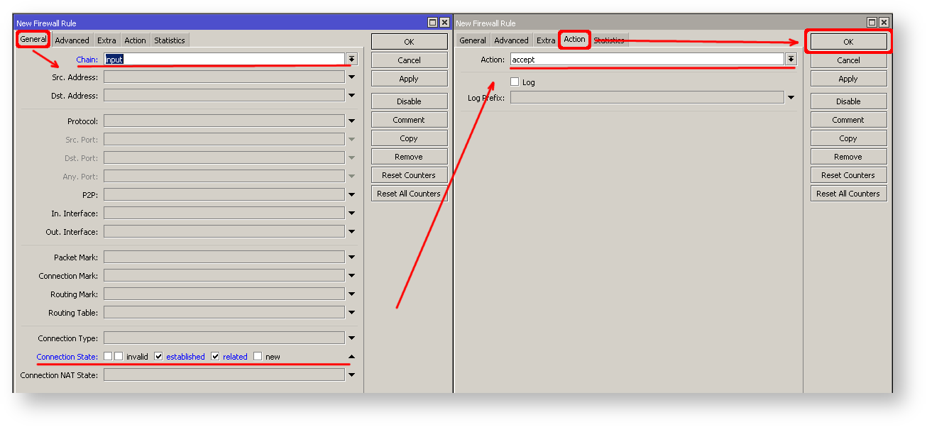
If you are using Winbox/Webfig for configuration, here is an example of how to add an established/related rule:
- Open Ip -> Firewall window, click on Filter rules tab;
- Click on the + button, a new dialog will open;
- Select chain input, click on Connection state, and select checkboxes for established and related;
- Click on the Action tab and make sure action accept is selected;
- Click on the Ok button to apply settings.
To add other rules click on + for each new rule and fill the same parameters as provided in the console example.
Administrative Services
Although the firewall protects the router from the public interface, you may still want to disable RouterOS services.
Most of RouterOS administrative tools are configured at the /ip service menu
Keep only secure ones,
/ip service disable telnet,ftp,www,api
Change default service ports, this will immediately stop most of the random SSH brute force login attempts:
/ip service set ssh port=2200
Additionally, each service can be secured by allowed IP address or address range(the address service will reply to), although more preferred method is to block unwanted access in firewall because the firewall will not even allow to open socket
/ip service set winbox address=192.168.88.0/24
Other Services
A bandwidth server is used to test throughput between two MikroTik routers. Disable it in the production environment.
/tool bandwidth-server set enabled=no
A router might have DNS cache enabled, which decreases resolving time for DNS requests from clients to remote servers. In case DNS cache is not required on your router or another router is used for such purposes, disable it.
/ip dns set allow-remote-requests=no
Some RouterBOARDs have an LCD module for informational purposes, set pin or disable it.
It is good practice to disable all unused interfaces on your router, in order to decrease unauthorized access to your router.
/interface print
/interface set x disabled=yes
Where «X» is a number of the unused interfaces.
RouterOS utilizes stronger crypto for SSH, most newer programs use it, to turn on SSH strong crypto:
/ip ssh set strong-crypto=yes
Following services are disabled by default, nevertheless, it is better to make sure that none of then were enabled accidentally:
- MikroTik caching proxy,
- MikroTik socks proxy,
- MikroTik UPNP service,
- MikroTik dynamic name service or IP cloud,
/ip cloud set ddns-enabled=no update-time=no
At this point, PC is not yet able to access the Internet, because locally used addresses are not routable over the Internet. Remote hosts simply do not know how to correctly reply to your local address.
The solution for this problem is to change the source address for outgoing packets to routers public IP. This can be done with the NAT rule:
/ip firewall nat
  add chain=srcnat out-interface=ether1 action=masquerade
In case if a public interface is a pppoe, then the out-interface should be set to «pppoe-out».
Another benefit of such a setup is that NATed clients behind the router are not directly connected to the Internet, that way additional protection against attacks from outside mostly is not required.
Port Forwarding
Some client devices may need direct access to the internet over specific ports. For example, a client with an IP address 192.168.88.254 must be accessible by Remote desktop protocol (RDP).
After a quick search on Google, we find out that RDP runs on TCP port 3389. Now we can add a destination NAT rule to redirect RDP to the client’s PC.
/ip firewall nat
  add chain=dstnat protocol=tcp port=3389 in-interface=ether1
    action=dst-nat to-address=192.168.88.254
If you have set up strict firewall rules then RDP protocol must be allowed in the firewall filter forward chain.
Setting up Wireless
For ease of use bridged wireless setup will be made so that your wired hosts are in the same Ethernet broadcast domain as wireless clients.
The important part is to make sure that our wireless is protected, so the first step is the security profile.
Security profiles are configured from /interface wireless security-profiles menu in a terminal.
/interface wireless security-profiles
  add name=myProfile authentication-types=wpa2-psk mode=dynamic-keys
    wpa2-pre-shared-key=1234567890
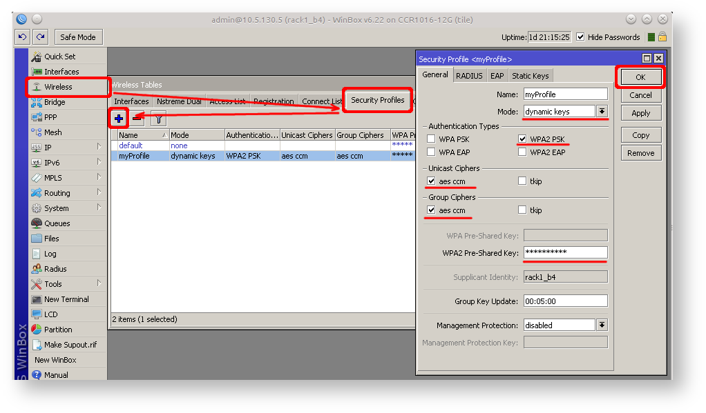
in Winbox/Webfig click on Wireless to open wireless windows and choose the Security Profile tab.
If there are legacy devices that do not support WPA2 (like Windows XP), you may also want to allow WPA protocol.
WPA and WPA2 pre-shared keys should not be the same.
Now when the security profile is ready we can enable the wireless interface and set the desired parameters
/interface wireless
enable wlan1;
set wlan1 band=2ghz-b/g/n channel-width=20/40mhz-Ce distance=indoors
mode=ap-bridge ssid=MikroTik-006360 wireless-protocol=802.11
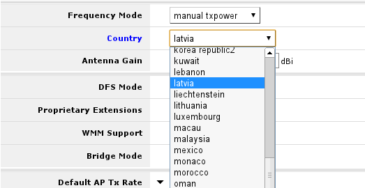
security-profile=myProfile frequency-mode=regulatory-domain
set country=latvia antenna-gain=3
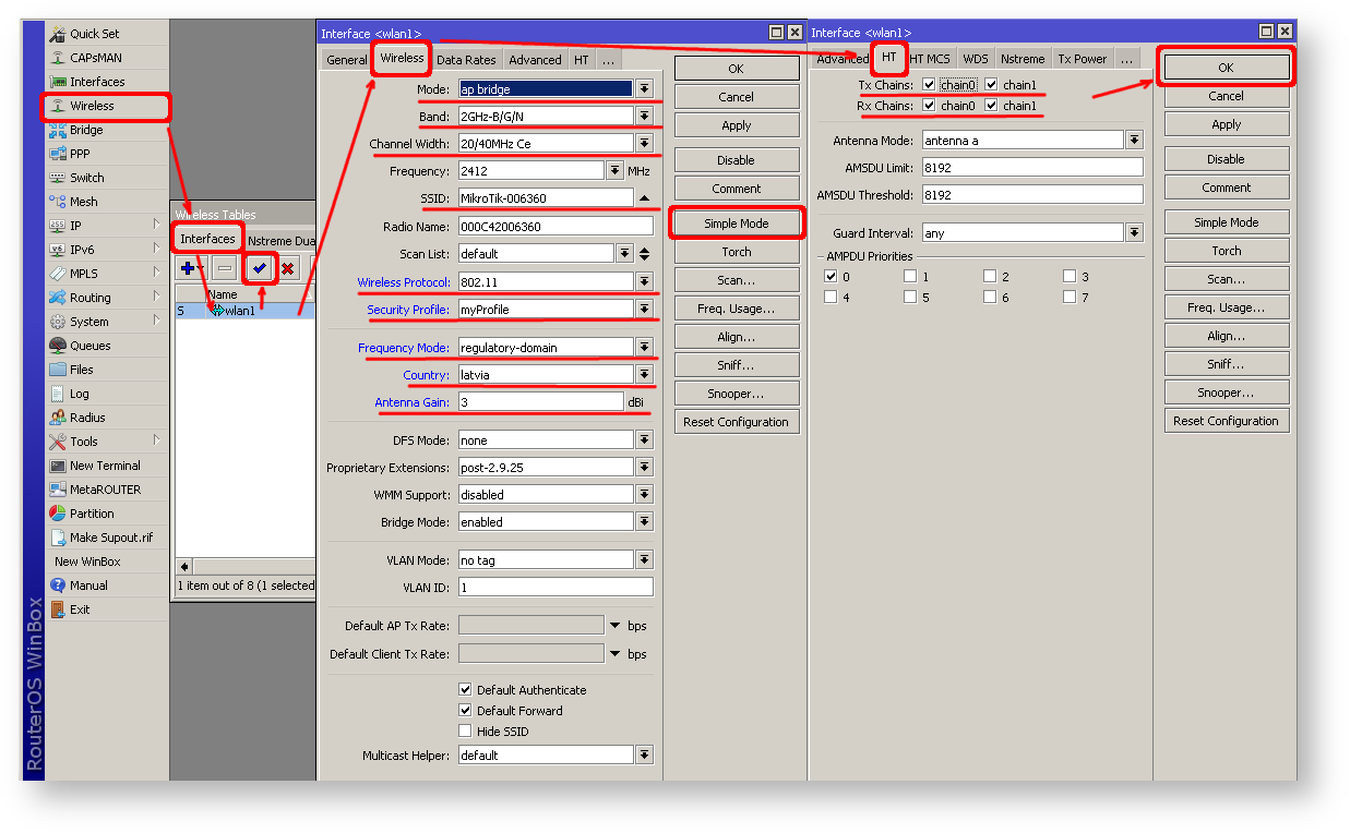
To do the same from Winbox/Webfig:
- Open Wireless window, select wlan1 interface, and click on the enable button;
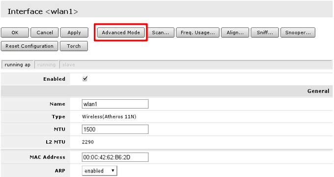
- Double click on the wireless interface to open the configuration dialog;
- In the configuration dialog click on the Wireless tab and click the Advanced mode button on the right side. When you click on the button additional configuration parameters will appear and the description of the button will change to Simple mode;
- Choose parameters as shown in the screenshot, except for the country settings and SSID. You may want to also choose a different frequency and antenna gain;
- Next, click on the HT tab and make sure both chains are selected;
- Click on the OK button to apply settings.
The last step is to add a wireless interface to a local bridge, otherwise connected clients will not get an IP address:
/interface bridge port
  add interface=wlan1 bridge=local
Now wireless should be able to connect to your access point, get an IP address, and access the internet.
Protecting the Clients
Now it is time to add some protection for clients on our LAN. We will start with a basic set of rules.
/ip firewall filter
  add chain=forward action=fasttrack-connection connection-state=established,related
    comment="fast-track for established,related";
  add chain=forward action=accept connection-state=established,related
    comment="accept established,related";
  add chain=forward action=drop connection-state=invalid
  add chain=forward action=drop connection-state=new connection-nat-state=!dstnat
    in-interface=ether1 comment="drop access to clients behind NAT from WAN"
A ruleset is similar to input chain rules (accept established/related and drop invalid), except the first rule with action=fasttrack-connection. This rule allows established and related connections to bypass the firewall and significantly reduce CPU usage.
Another difference is the last rule which drops all new connection attempts from the WAN port to our LAN network (unless DstNat is used). Without this rule, if an attacker knows or guesses your local subnet, he/she can establish connections directly to local hosts and cause a security threat.
For more detailed examples on how to build firewalls will be discussed in the firewall section, or check directly Building Your First Firewall article.
Blocking Unwanted Websites
Sometimes you may want to block certain websites, for example, deny access to entertainment sites for employees, deny access to porn, and so on. This can be achieved by redirecting HTTP traffic to a proxy server and use an access-list to allow or deny certain websites.
First, we need to add a NAT rule to redirect HTTP to our proxy. We will use RouterOS built-in proxy server running on port 8080.
/ip firewall nat
  add chain=dst-nat protocol=tcp dst-port=80 src-address=192.168.88.0/24
    action=redirect to-ports=8080
Enable web proxy and drop some websites:
/ip proxy set enabled=yes
/ip proxy access add dst-host=www.facebook.com action=deny
/ip proxy access add dst-host=*.youtube.* action=deny
/ip proxy access add dst-host=:vimeo action=deny
Using Winbox:
- On the left menu navigate to IP -> Web Proxy
- Web proxy settings dialog will appear.
- Check the «Enable» checkbox and click on the «Apply» button
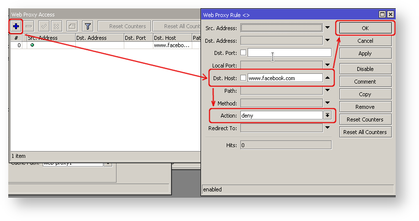
- Then click on the «Access» button to open the «Web Proxy Access» dialog
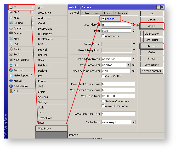
- In the «Web Proxy Access» dialog click on «+» to add a new Web-proxy rule
- Enter Dst hostname that you want to block, in this case, «www.facebook.com», choose the action «deny»
- Then click on the «Ok» button to apply changes.
- Repeat the same to add other rules.
Troubleshooting
RouterOS has built-in various troubleshooting tools, like ping, traceroute, torch, packet sniffer, bandwidth test, etc.
We already used the ping tool in this article to verify internet connectivity.
Troubleshoot if ping fails
The problem with the ping tool is that it says only that destination is unreachable, but no more detailed information is available. Let’s overview the basic mistakes.
You cannot reach www.google.com from your computer which is connected to a MikroTik device:
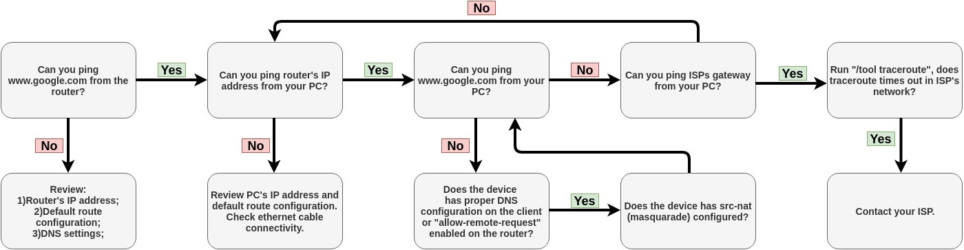
If you are not sure how exactly configure your gateway device, please reach MikroTik’s official consultants for configuration support.
Summary
Congratulations, you have got hold of MikroTik router for your home network. This guide will help you to do initial configuration of the router to make your home network a safe place to be.
The guide is mostly intended in case if default configuration did not get you to the internet right away, however some parts of the guide is still useful.
Connecting wires
Router’s initial configuration should be suitable for most of the cases. Description of the configuration is on the back of the box and also described in the online manual.
The best way to connect wires as described on the box:
- Connect ethernet wire from your internet service provider (ISP) to port ether1, rest of the ports on the router are for local area network (LAN). At this moment, your router is protected by default firewall configuration so you should not worry about that;
- Connect LAN wires to the rest of the ports.
Configuring router
Initial configuration has DHCP client on WAN interface (ether1), rest of the ports are considered your local network with DHCP server configured for automatic address configuration on client devices. To connect to the router you have to set your computer to accept DHCP settings and plug in the ethernet cable in one of the LAN ports (please check routerboard.com for port numbering of the product you own, or check front panel of the router).
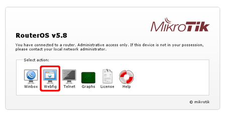
Logging into the router
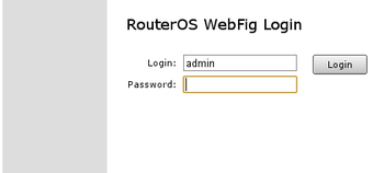
To access the router enter address 192.168.88.1 in your browser. Main RouterOS page will be shown as in the screen shot below. Click on WebFig from the list.
You will be prompted for login and password to access configuration interface. Default login name is admin and blank password (leave empty field as it is already).
Router user accounts
It is good idea to start with password setup or add new user so that router is not accessible by anyone on your network.
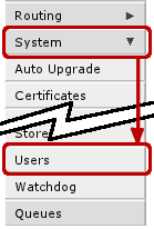
User configuration is done form System -> Users menu.
To access this menu, click on System on the left panel and from the dropdown menu choose Users (as shown in screenshot on the left)
You will see this screen, where you can manage users of the router.
In this screen you can edit or add new users:
- When you click on account name (in this case admin), edit screen for the user will be displayed.
- If you click on Add new button, new user creation screen will be displayed.
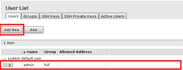
Both screens are similar as illustrated in screenshot below.
After editing user’s data click OK (to accept changes) or Cancel. It will bring you back to initial screen of user management.
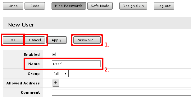
In user edit/Add new screen you can alter existing user or create new. Field marked with 2. is the user name, field 1. will open password screen, where old password for the user can be changed or added new one (see screenshot below).
Configure access to internet
If initial configuration did not work (your ISP is not providing DHCP server for automatic configuration) then you will have to have details from your ISP for static configuration of the router. These settings should include
- IP address you can use
- Network mask for the IP address
- Default gateway address
Less important settings regarding router configuration:
- DNS address for name resolution
- NTP server address for time automatic configuration
- Your previous MAC address of the interface facing ISP
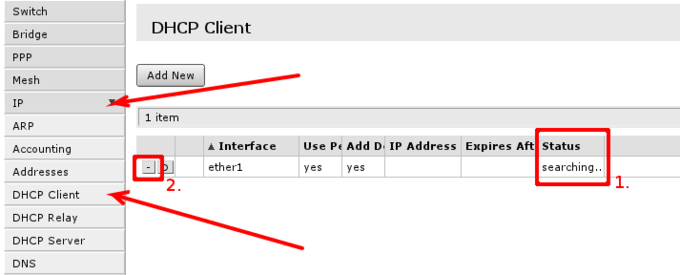
DHCP Client
Default configuration is set up using DHCP-Client on interface facing your ISP or wide area network (WAN). It has to be disabled if your ISP is not providing this service in the network. Open ‘IP -> DHCP Client’ and inspect field 1. to see status of DHCP Client, if it is in state as displayed in screenshot, means your ISP is not providing you with automatic configuration and you can use button in selection 2. to remove DHCP-Client configured on the interface.
Static IP Address
To manage IP addresses of the router open ‘IP -> Address’
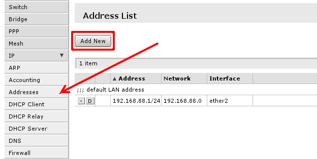
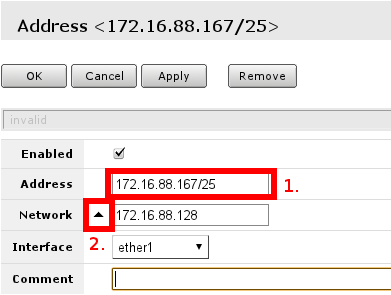
You will have one address here — address of your local area network (LAN) 192.168.88.1 one you are connected to router. Select Add new to add new static IP address to your router’s configuration.
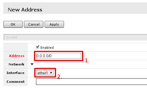
You have to fill only fields that are marked. Field 1. should contain IP address provided by your ISP and network mask’. Examples:
172.16.88.67/24
both of these notations mean the same, if your ISP gave you address in one notation, or in the other, use one provided and router will do the rest of calculation.
Other field of interest is interface this address is going to be assigned. This should be interface your ISP is connected to, if you followed this guide — interface contains name — ether1
![]()
Note: While you type in the address, webfig will calculate if address you have typed is acceptable, if it is not label of the field will turn red, otherwise it will be blue
![]()
Note: It is good practice to add comments on the items to give some additional information for the future, but that is not required
Configuring network address translation (NAT)
Since you are using local and global networks, you have to set up network masquerade, so that your LAN is hidden behind IP address provided by your ISP. That should be so, since your ISP does not know what LAN addresses you are going to use and your LAN will not be routed from global network.
To check if you have the source NAT open ‘IP -> Firewall -> tab NAT’ and check if item highlighted (or similar) is in your configuration.
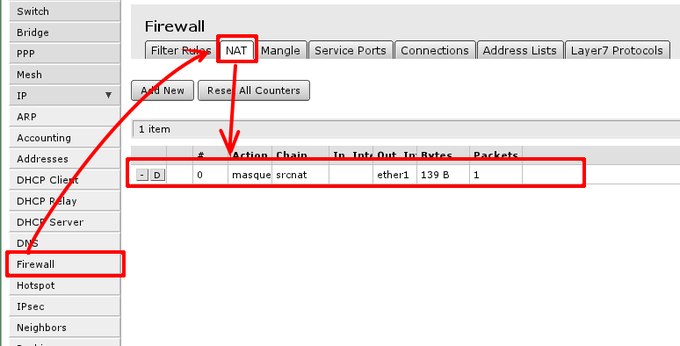
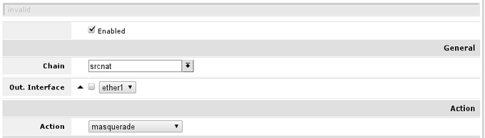
Essential fields for masquerade to work:
- enabled is checked;
- chain — should be srcnat;
- out-interface is set to interface connected to your ISP network, Following this guide ether1;
- action should be set to masquerade.
In screenshot correct rule is visible, note that irrelevant fields that should not have any value set here are hidden (and can be ignored)
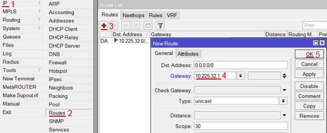
Default gateway
under ‘IP -> Routes’ menu you have to add routing rule called default route. And select Add new to add new route.
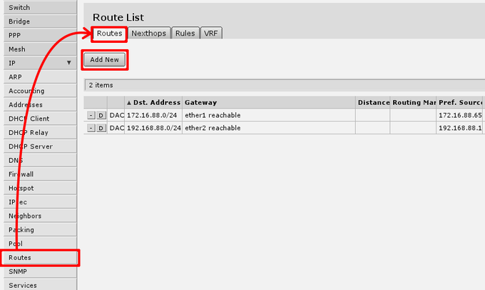
In screen presented you will see the following screen:
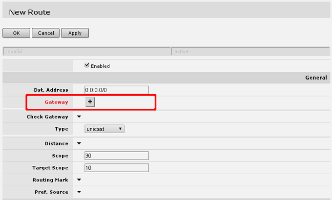
here you will have to press button with + near red Gateway label and enter in the field default gateway, or simply gateway given by your ISP.
This should look like this, when you have pressed the + button and enter gateway into the field displayed.
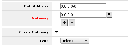
After this, you can press OK button to finish creation of the default route.
At this moment, you should be able to reach any globally available host on the Internet using IP address.
To check weather addition of default gateway was successful use Tools -> Ping
Domain name resolution
To be able to open web pages or access Internet hosts by domain name DNS should be configured, either on your router or your computer. In scope of this guide, i will present only option of router configuration, so that DNS addresses are given out by DHCP-Server that you are already using.
This can be done in ‘IP -> DNS ->Settings’, first Open ‘IP ->DNS’:
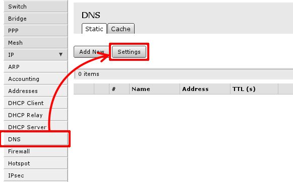
Then select Settings to set up DNS cacher on the router. You have to add field to enter DNS IP address, section 1. in image below. and check Allow Remote Requests marked with 2.
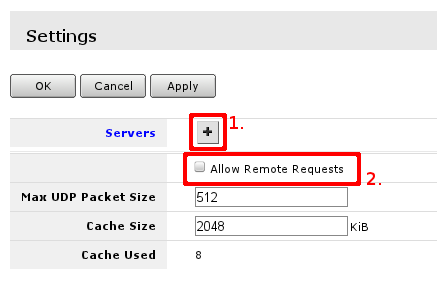
The result of pressing + twice will result in 2 fields for DNS IP addresses:

![]()
Note: Filling acceptable value in the field will turn field label blue, other way it will be marked red.
SNTP Client
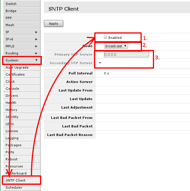
RouterBOARD routers do not keep time between restarts or power failuers. To have correct time on the router set up SNTP client if you require that.
To do that, go to ‘System -> SNTP’ where you have to enable it, first mark, change mode from broadcast to unicast, so you can use global or ISP provided NTP servers, that will allow to enter NTP server IP addresses in third area.
Setting up Wireless
For ease of use bridged wireless setup will be used, so that your wired hosts will be in same ethernet broadcast domain as wireless clients.
To make this happen several things has to be checked:
- Ethernet interfaces designated for LAN are swtiched or bridged, or they are separate ports;
- If bridge interface exists;
- Wireless interface mode is set to ap-bridge (in case, router you have has level 4 or higher license level), if not, then mode has to be set to bridge and only one client (station) will be able to connect to the router using wireless network;
- There is appropriate security profile created and selected in interface settings.
Check Ethernet interface state
![]()
Warning: Changing settings may affect connectivity to your router and you can be disconnected from the router. Use Safe Mode so in case of disconnection made changes are reverted back to what they where before you entered safe mode
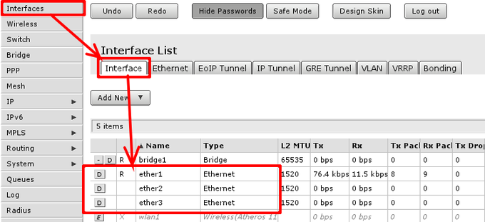
To check if ethernet port is switched, in other words, if ethernet port is set as slave to another port go to ‘Interface’ menu and open Ethernet interface details. They can be distinguished by Type column displaying Ethernet.
When interface details are opened, look up Master Port setting.
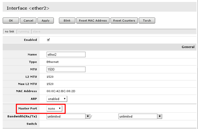
Available settings for the attribute are none, or one of Ethernet interface names. If name is set, that mean, that interface is set as slave port. Usually RouterBOARD routers will come with ether1 as intended WAN port and rest of ports will be set as slave ports of ether2 for LAN use.
Check if all intended LAN Ethernet ports are set as slave ports of the rest of one of the LAN ports. For example, if ether2. ether3, ether4 and ether5 are intended as LAN ports, set on ether3 to ether5 attribute Master Port to ether2.
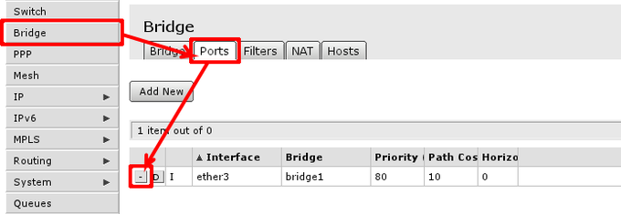
In case this operation fails — means that Ethernet interface is used as port in bridge, you have to remove them from bridge to enable hardware packet switching between Ethernet ports. To do this, go to Bridge -> Ports and remove slave ports (in example, ether3 to ether5) from the tab.
![]()
Note: If master port is present as bridge port, that is fine, intended configuration requires it there, same applies to wireless interface (wlan)
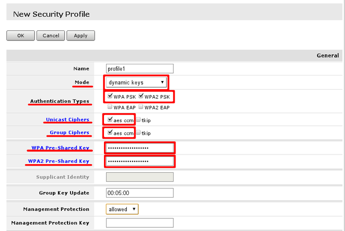
Security profile
It is important to protect your wireless network, so no malicious acts can be performed by 3rd parties using your wireless access-point.
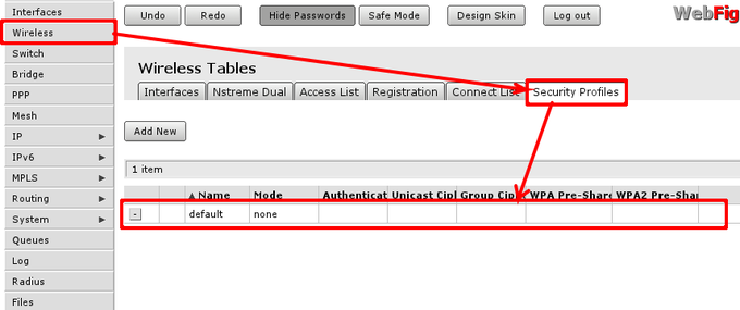
To edit or create new security profile head to ‘Wireless -> tab ‘Security Prodiles’ and choose one of two options:
- Using Add new create new profile;
- Using highlighted path in screenshot edit default profile that is already assigned to wireless interface.
In This example i will create new security profile, editing it is quite similar. Options that has to be set are highlighted with read and recommended options are outlined by red boxes and pre-set to recommended values. WPA and WPA2 is used since there are still legacy equipment around (Laptops with Windows XP, that do not support WPA2 etc.)
WPA Pre- shared key and WPA2 Pre- shared key should be entered with sufficient length. If key length is too short field label will indicate that by turning red, when sufficient length is reached it will turn blue.
![]()
Note: WPA and WPA2 pre-shared keys should be different
![]()
Note: When configuring this, you can deselect Hide passwords in page header to see the actual values of the fields, so they can be successfully entered into device configuration that are going to connect to wireless access-point
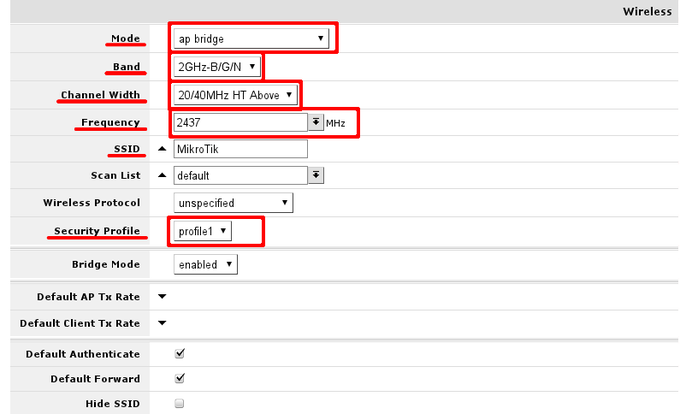
Wireless settings
Adjusting wireless settings. That can be done here:
In General section adjust settings to settings as shown in screenshot. Consider these safe, however it is possible, that these has to be adjusted slightly.
Interface mode has to be set to ap-bridge, if that is not possible (license resctrictions) set to bridge, so one client will be able to connect to device.
WiFI devices usually are designed with 2.4GHz modes in mind, setting band to 2GHz-b/g/n will enable clients with 802.11b, 802.11g and 802.11n to connect to the access point
Adjust channel width to enable faster data rates for 802.11n clients. In example channel 6 is used, as result, 20/40MHz HT Above or 20/40 MHz HT Below can be used. Choose either of them.
Set SSID — the name of the access point. It will be visible when you scan for networks using your WiFi equipment.
In section HT set change HT transmit and receive chains. It is good practice to enable all chains that are available
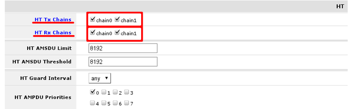
When settings are set accordingly it is time to enable our protected wireless access-point
Bridge LAN with Wireless
Open Bridge menu and check if there are any bridge interface available first mark. If there is not, select Add New marked with second mark and in the screen that opens just accept the default settings and create interface. When bridge interface is availbe continue to Ports tab where master LAN interface and WiFI interface have to be added.
First marked area is where interfaces that are added as ports to bridge interface are visible. If there are no ports added, choose Add New to add new ports to created bridge interfaces.
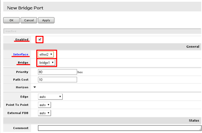
When new bridge port is added, select that it is enabled (part of active configuration), select correct bridge interface, following this guide — there should be only 1 interface. And select correct port — LAN interface master port and WiFi port
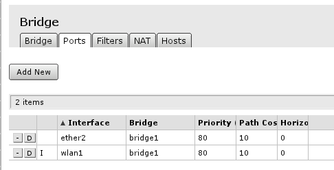
Finished look of bridge configured with all ports required
Troubleshooting & Advanced configuration
This section is here to make some deviations from configuration described in the guide itself. It can require more understanding of networking, wireless networks in general.
General
Check IP address
Adding IP address with wrong network mask will result in wrong network setting. To correct that problem it is required to change address field, first section, with correct address and network mask and network field with correct network, or unset it, so it is going to be recalculated again
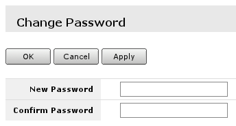
Change password for current user
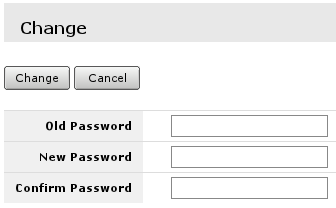
To change password of the current user, safe place to go is System -> Password
Where all the fields has to be filled.
There is other place where this can be done in case you have full privileges on the router.
Change password for existing user
If you have full privileges on the router, it is possible to change password for any user without knowledge of current one. That can be done under System -> Users menu.
Steps are:
- Select user;
- type in password and re-type it to know it is one you intend to set
No access to the Internet or ISP network
If you have followed this guide to the letter but even then you can only communicate with your local hosts only and every attempt to connect to Internet fails, there are certain things to check:
- If masquerade is configured properly;
- If setting MAC address of previous device on WAN interface changes anything
- ISP has some captive portal in place.
Respectively, there are several ways how to solve the issue, one — check configuration if you are not missing any part of configuration, second — set MAC address. Change of mac address is available only from CLI — New Terminal from the left side menu. If new window is not opening check your browser if it is allowing to open popup windows for this place. There you will have to write following command by replacing MAC address to correct one:
/interface ethernet set ether1 mac-address=XX:XX:XX:XX:XX:XX
Or contact your ISP for details and inform that you have changed device.
Checking link
There are certain things that are required for Ethernet link to work:
- Link activity lights are on when Ethernet wire is plugged into the port
- Correct IP address is set on the interface
- Correct route is set on the router
What to look for using ping tool:
- If all packets are replied;
- If all packets have approximately same round trip time (RTT) on non-congested Ethernet link
It is located here: Tool -> Ping menu. Fill in Ping To field and press start to initiate sending of ICMP packets.
Wireless
Wireless unnamed features in the guide that are good to know about. Configuration adjustments.
Channel frequencies and width
It is possible to choose different frequency, here are frequencies that can be used and channel width settings to use 40MHz HT channel (for 802.11n). For example, using channel 1 or 2412MHz frequency setting 20/40MHz HT below will not yield any results, since there are no 20MHz channels available below set frequency.
| Channel # | Frequency | Below | Above |
|---|---|---|---|
| 1 | 2412 MHz | no | yes |
| 2 | 2417 MHz | no | yes |
| 3 | 2422 MHz | no | yes |
| 4 | 2427 MHz | no | yes |
| 5 | 2432 MHz | yes | yes |
| 6 | 2437 MHz | yes | yes |
| 7 | 2442 MHz | yes | yes |
| 8 | 2447 MHz | yes | yes |
| 9 | 2452 MHz | yes | yes |
| 10 | 2457 MHz | yes | yes |
| 11 | 2462 MHz | yes | no |
| 12 | 2467 MHz | yes | no |
| 13 | 2472 MHz | yes | no |
![]()
Warning: You should check how many and what frequencies you have in your regulatory domain before. If there are 10 or 11 channels adjust settings accordingly. With only 10 channels, channel #10 will have no sense of setting 20/40MHz HT above since no full 20MHz channel is available
Wireless frequency usage
If wireless is not performing very well even when data rates are reported as being good, there might be that your neighbours are using same wireless channel as you are. To make sure follow these steps:
- Open frequency usage monitoring tool Freq. Usage… that is located in wireless interface details;
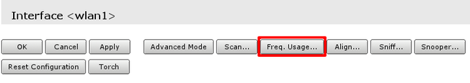
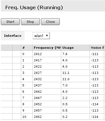
- Wait for some time as scan results are displayed. Do that for minute or two. Smaller numbers in Usage column means that channel is less crowded.
![]()
Note: Monitoring is performed on default channels for Country selected in configuration. For example, if selected country would be Latvia, there would have been 13 frequencies listed as at that country have 13 channels allowed.
Change Country settings
By default country attribute in wireless settings is set to no_country_set. It is good practice to change this (if available) to change country you are in. To do that do the following:
- Go to wireless menu and select Advanced mode;
- Look up Country attribute and from drop-down menu select country
![]()
Note: Advanced mode is toggle button that changes from Simple to Advanced mode and back.
Port forwarding
To make services on local servers/hosts available to general public it is possible to forward ports from outside to inside your NATed network, that is done from /ip firewall nat menu. For example, to make possible for remote helpdesk to connect to your desktop and guide you, make your local file cache available for you when not at location etc.
Static configuration
A lot of users prefer to configure these rules statically, to have more control over what service is reachable from outside and what is not. This also has to be used when service you are using does not support dynamic configuration.
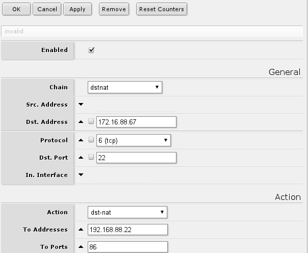
Following rule will forward all connections to port 22 on the router external ip address to port 86 on your local host with set IP address:
if you require other services to be accessible you can change protocol as required, but usually services are running TCP and dst-port. If change of port is not required, eg. remote service is 22 and local is also 22, then to-ports can be left unset.
Comparable command line command:
 /ip firewall nat add chain=dstnat dst-address=172.16.88.67 protocol=tcp dst-port=22
 action=dst-nat to-address=192.168.88.22 to-ports=86
![]()
Note: Screenshot contain only minimal set of settings are left visible
Dynamic configuration
uPnP is used to enable dynamic port forwarding configuration where service you are running can request router using uPnP to forward some ports for it.
![]()
Warning: Services you are not aware of can request port forwarding. That can compromise security of your local network, your host running the service and your data
Configuring uPnP service on the router:
- Set up what interfaces should be considered external and what internal;
 /ip upnp interface add interface=ether1 type=external
 /ip upnp interface add interface=ether2 type=internal
- Enable service itself
/ip upnp set allow-disable-external-interface=no show-dummy-rule=no enabled=yes
Limiting access to web pages
Using IP -> Web Proxy it is possible to limit access to unwanted web pages. This requires some understanding of use of WebFig interface.
Set up Web Proxy for page filtering
From IP -> Web Proxy menu Access tab open Web Proxy Settings and make sure that these attributes are set follows:
 Enabled -> checked
 Port -> 8080
 Max. Cache Size -> none
 Cache on disk -> unchecked
 Parent proxy -> unset
When required alterations are done applysettings to return to Access tab.
Set up Access rules
This list will contain all the rules that are required to limit access to sites on the Internet.
To add sample rule to deny access to any host that contain example.com do the following when adding new entry:
 Dst. Host -> .*example.com.*
 Action -> Deny
With this rule any host that has example.com will be unaccessible.
Limitation strategies
There are two main approaches to this problem
- deny only pages you know you want to deny (A)
- allow only certain pages and deny everything else (B)
For approach A each site that has to be denied is added with Action set to Deny
For approach B each site that has to be allowed should be added with Action set to Allow and in the end is rule, that matches everything with Action set to Deny.
[ Top | Back to Content ]
Добавлено 5 июня 2019 в 00:04
Это инструкция, как пошагово настроить роутер MikroTik с нуля без использования заводской конфигурации.
Содержание:
Подключение роутера MikroTik
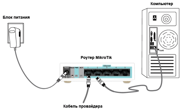
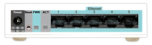
Схема подключения роутера MikroTik:
- кабель провайдера интернета подключаем в первый порт роутера;
- компьютер подключаем к роутеру MikroTik сетевым кабелем в любой LAN порт от 2 до 5;
- ноутбук и другие беспроводные устройства подключим по Wi-Fi;
- блок питания включаем в разъем «Power» роутера MikroTik.

Настройка сетевой карты компьютера
Чтобы на компьютере можно было зайти в настройки роутера Mikrotik, настроим сетевую карту на получение автоматических настроек.
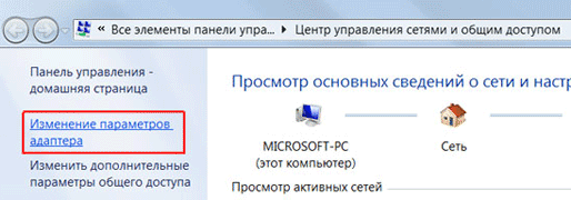
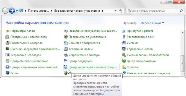
Открываем «Пуск» → «Панель управления» → «Центр управления сетями и общим доступом».

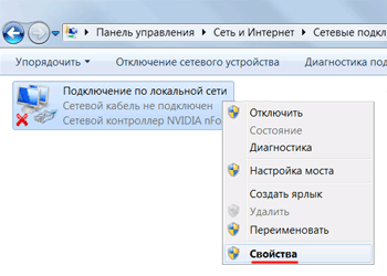
Перейдем в «Изменение параметров адаптера».
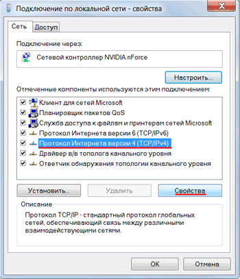
Нажимаем правой кнопкой мыши на «Подключение по локальной сети» и выбираем «Свойства»

Нажимаем на «Протокол Интернета версии 4 (TCP/IPv4)» и кнопку «Свойства».

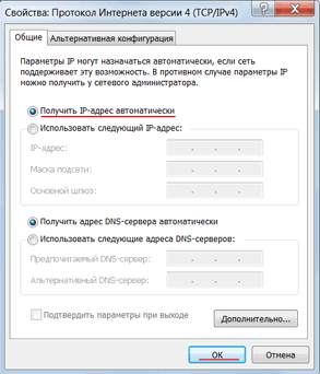
Выбираем «Получить IP-адрес автоматически» и нажимаете кнопку «OK».

Если сетевая карта не получает автоматически IP адрес из подсети 192.168.88.x, попробуйте его указать вручную (например: 192.168.88.21) или сбросить роутер Mikrotik к заводским настройкам.
Вход в настройки роутера MikroTik
Выполнить настройку роутера MikroTik можно разными способами:
- С помощью специальной программы Winbox для ОС Windows. Скачать на официальном сайте.
- С помощью браузера, перейдя по адресу 192.168.88.1. В настройках браузера не должен быть указан proxy-сервер!
- Настройка через Telnet.
Мы будем настраивать роутер Mikrotik с помощью программы Winbox.
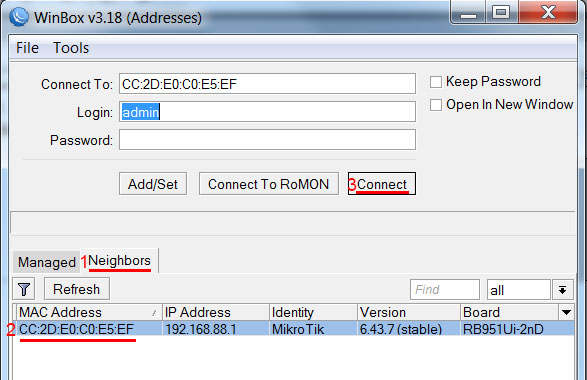
Подключаемся к роутеру MikroTik:
- Запустите программу Winbox и перейдите на вкладку Neighbors;
- В списке отобразится ваш роутер. Нажмите левой кнопкой мыши на его MAC адрес;
- Нажмите кнопку Connect.
Login по умолчанию admin, пароль пустой.
Сброс настроек роутера
Сбросим все настройки роутера MikroTik.
При первом входе у вас появится окно, как на картинке ниже. Нажмите кнопку Remove Configuration и дождитесь перезагрузки устройства.
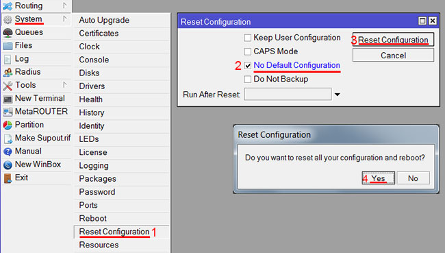
Если у вас не появилось данное окно, сбросим настройки через меню:
- Выбираем слева меню System — Reset Configuration;
- Поставьте галочку No Default Configuration;
- Нажмите кнопку Reset Configuration.
- Нажмите кнопку Yes и дождитесь перезагрузки устройства.
Описание сетевых интерфейсов
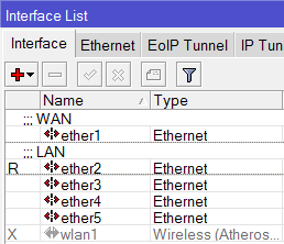
Конфигурация сетевых интерфейсов MikroTik будет выглядеть следующим образом: первый порт ether1 будет подключен к провайдеру (WAN порт), остальные порты ether2-5 будут работать в режиме коммутатора для подключения компьютеров локальной сети.
Чтобы не путать сетевые интерфейсы, опишем их с помощью комментариев.
Входим в настройки MikroTik с помощью программы Winbox.
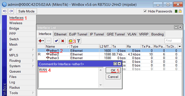
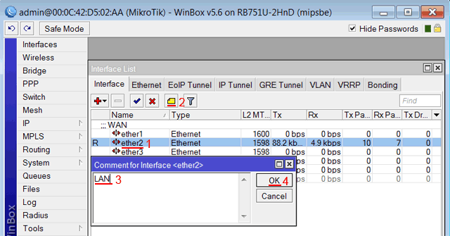
Записываем для первого порта ether1 комментарий «WAN»:
- Открываем меню Interfaces;
- Выбираем первый интерфейс ether1;
- Нажимаем желтую кнопку Comment;
- В появившемся окне вводим комментарий «WAN«;
- Нажимаем кнопку OK.
Записываем для второго порта ether2 комментарий «LAN»:
Выбираем интерфейс ether2;
Нажимаем желтую кнопку Comment;
В появившемся окне вводим комментарий «LAN«;
Нажимаем кнопку OK.

Теперь в списке интерфейсов четко видно их назначение.

Настройка WAN интерфейса MikroTik
Смена MAC адреса WAN порта
Если Ваш провайдер блокирует доступ к сети по MAC адресу, то необходимо сначала изменить MAC адрес WAN порта роутера MikroTik. В противном случае пропустите этот пункт.
Чтобы изменить MAC адрес порта MikroTik, открываем в программе Winbox меню New Terminal и вводим команду:
/interface ethernet set ether1 mac-address=00:01:02:03:04:05, где ether1 — имя WAN интерфейса, 00:01:02:03:04:05 — разрешенный MAC адрес.

Чтобы вернуть родной MAC адрес порта, нужно выполнить команду:
/interface ethernet reset-mac ether1, где ether1 — имя интерфейса.

Настройка Dynamic IP
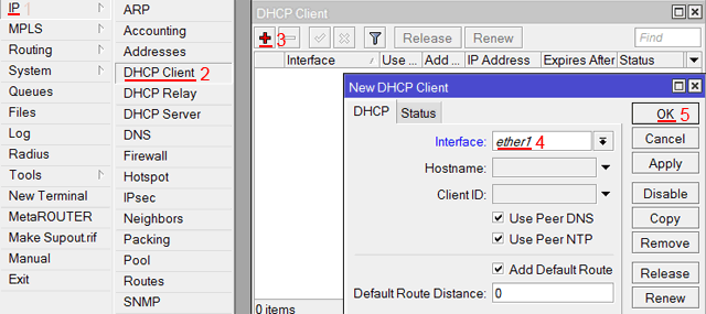
Если интернет провайдер выдает Вам сетевые настройки автоматически, то необходимо настроить WAN порт роутера MikroTik на получение настроек по DHCP:
- Открываем меню IP;
- Выбираем DHCP Client;
- В появившемся окне нажимаем кнопку Add (плюсик);
- В новом окне в списке Interface выбираем WAN интерфейс ether1;
- Нажимаем кнопку OK для сохранения настроек.

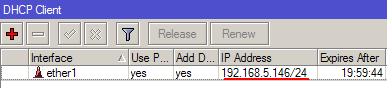
Теперь мы получили IP адрес от провайдера, который отображается в столбце IP Adress.

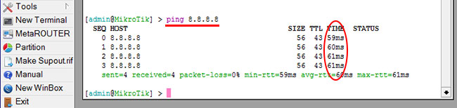
Проверим, что есть связь с интернетом:
- Открываем меню New Terminal;
- В терминале пишем команду ping 8.8.8.8 (пингуем сайт google) и жмем Enter на клавиатуре.
Как видим, идут пинги по 60ms, значит интернет подключен и работает. Остановить выполнение команды можно комбинацией клавиш на клавиатуре Ctrl+C.

На компьютерах, подключенных к роутеру MikroTik, интернет не будет работать, пока вы не настроите локальную сеть, Firewall и NAT.
Настройка Static IP
Если вы используете статические сетевые настройки, необходимо настроить WAN порт роутера MikroTik вручную.
Настроим статический IP адрес и маску подсети WAN порта MikroTik :
- Открываем меню IP;
- Выбираем Addresses;
- В появившемся окне нажимаем кнопку Add (плюсик);
- В новом окне в поле Address прописываем статический IP адрес / маску подсети;
- В списке Interface выбираем WAN интерфейс ether1;
- Для сохранения настроек нажимаем кнопку OK.

Настроим адрес интернет шлюза MikroTik:
- Открываем меню IP;
- Выбираем Routes;
- В появившемся окне нажимаем кнопку Add (плюсик);
- В новом окне в поле Gateway прописываем IP адрес шлюза;
- Нажимаем кнопку OK для сохранения настроек.

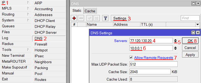
Добавим адреса DNS серверов MikroTik:
- Открываем меню IP;
- Выбираем DNS;
- В появившемся окне нажимаем кнопку Settings;
- В новом окне в поле Servers прописываем IP адрес предпочитаемого DNS сервера;
- Нажимаем кнопку «вниз» (черный треугольник), чтобы добавить еще одно поле для ввода;
- В новом поле прописываем IP адрес альтернативного DNS сервера;
- Ставим галочку Allow Remote Requests;
- Нажимаем кнопку OK для сохранения настроек.
Проверим, что есть доступ к интернету:
- Открываем меню New Terminal;
- В терминале пишем команду ping 8.8.8.8 (пингуем сайт google) и жмем Enter на клавиатуре.
Как видим, идут пинги по 60ms, значит интернет подключен и работает. Остановить выполнение команды можно комбинацией клавиш на клавиатуре Ctrl+C.
На компьютерах, подключенных к роутеру MikroTik, интернет не будет работать, пока вы не настроите локальную сеть, Firewall и NAT.
Настройка PPPoE
Если вы используете ADSL модем, к которому по сетевому кабелю подключен роутер MikroTik, сначала необходимо настроить ADSL модем в режим Bridge (мост).
Настроим клиентское PPPoE соединение на роутере MikroTik:
- Слева выбираем меню PPP;
- Нажимаем кнопку Add (плюсик);
- Выбираем PPPoE Client.

Настраиваем параметры PPPoE соединения MikroTik:
- В поле Name указываем имя соединения;
- В списке Interfaces выбираем первый WAN порт ether1, который подключен к провайдеру;

Выбор интерфейса PPPoE MikroTik - Переходим на вкладку Dial Out;
- В поле User указываем имя пользователя;
- В поле Password вводим пароль;
- Ставим галочку Use Peer DNS;
- Нажимаем кнопку OK.


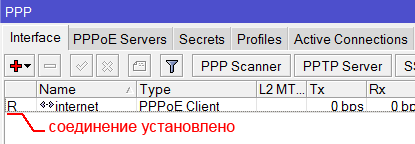
После создания PPPoE соединения напротив него должна появиться буква R, которая говорит о том, что соединение установлено.

Проверим, что есть связь с интернетом:
- Открываем меню New Terminal;
- В терминале пишем команду ping 8.8.8.8 (пингуем сайт google) и жмем Enter на клавиатуре.
Как видим, идут пинги по 60ms, значит интернет подключен и работает. Остановить выполнение команды можно комбинацией клавиш на клавиатуре Ctrl+C.

На компьютерах, подключенных к роутеру MikroTik, интернет не будет работать, пока вы не настроите локальную сеть, Firewall и NAT.
Настройка локальной сети MikroTik
Объединение Wi-Fi и проводных интерфейсов в локальную сеть
Чтобы компьютеры, подключенные к роутеру по кабелю и по Wi-Fi, друг друга «видели», необходимо объединить беспроводной и проводные интерфейсы MikroTik. Если у вас роутер без Wi-Fi, то объединяете только проводные интерфейсы.
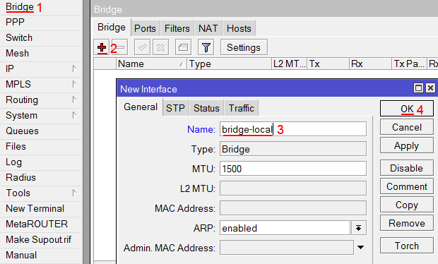
Создаем объединение bridge-local (мост);
- Открываем меню Bridge;
- Нажимаем кнопку Add (плюсик);
- В поле Name прописываем имя объединения bridge-local;
- Нажимаем кнопку OK.

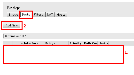
Добавляем в объединение проводные ethetnet порты 2-5:
- Переходим на вкладку Ports;
- Нажимаем кнопку Add (плюсик);
- В списке Interface выбираем ethernet порт ether2;
- В списке Bridge выбираем имя объединения bridge-local;
- Нажимаем кнопку OK;
- Точно так же добавляем порты ether3, ether4, ether5.

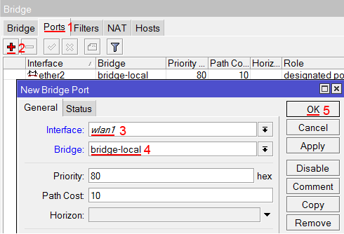
Добавляем в объединение Wi-Fi интерфейс.
- Переходим на вкладку Ports;
- Нажимаем кнопку Add (плюсик);
- В списке Interface выбираем беспроводной интерфейс wlan1;
- В списке Bridge выбираем имя объединения bridge-local;
- Нажимаем кнопку OK.

Назначение IP адреса локальной сети
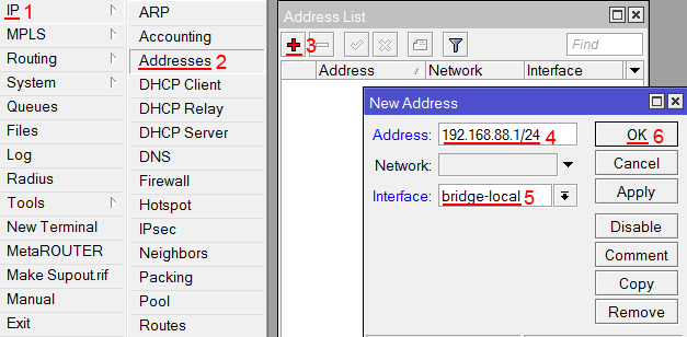
Настроим IP адрес локальной сети MikroTik:
- Открываем меню IP;
- Выбираем Addresses;
- Нажимаем кнопку Add (плюсик);
- В поле Address вводим адрес и маску локальной сети, например 192.168.88.1/24;
- В списке Interface выбираем bridge-local;
- Нажимаем кнопку OK.
Настройка DHCP сервера
Чтобы компьютеры, подключенные к роутеру, получали сетевые настройки автоматически, настроим DHCP сервер MikroTik:
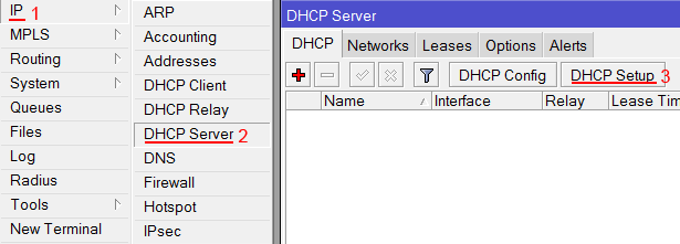
- Открываем меню IP;
- Выбираем DHCP Server;
- Нажимаем кнопку DHCP Setup;
Настройка DHCP сервера MikroTik - В списке DHCP Server Interface выбираем bridge-local;
- Нажимаем кнопку Next;
Выбор интерфейса DHCP сервера MikroTik - В этом окне выбирается сеть для DHCP. Оставляем без изменений и нажимаем кнопку Next;
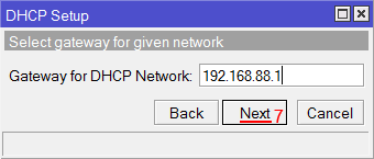
Настройка IP адрес локальной сети MikroTik - В следующем окне указывается адрес шлюза. Нажимаем кнопку Next;
Настройка IP адрес шлюза для локальной сети MikroTik - В этом окне прописывается диапазон IP адресов, которые будет раздавать DHCP сервер. Нажимаем кнопку Next;
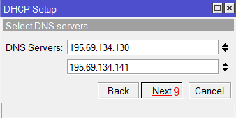
Настройка диапазона IP адресов DHCP сервера MikroTik - Далее вводятся адреса DNS серверов. Нажимаем кнопку Next;
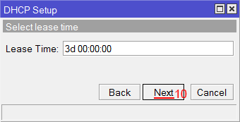
Настройка DNS серверов DHCP сервера MikroTik - Здесь задается время резервирования IP адресов. Нажимаем кнопку Next;
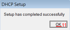
Время резервирования IP адресов - Настройка DHCP сервера успешно завершена. Жмем кнопку OK.
Настройка DHCP сервера MikroTik успешно завершена


Теперь сетевой кабель компьютера отключаем от роутера и еще раз подключаем к нему.
Настройка Wi-Fi точки доступа MikroTik
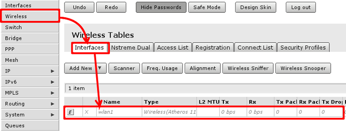
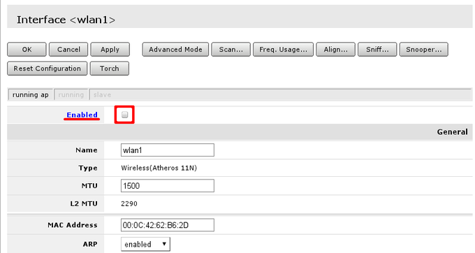
Сначала необходимо включить Wi-Fi модуль:
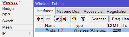
- Открываем меню Wireless;
- Выбираем Wi-Fi интерфейс wlan1;
- Нажимаем кнопку Enable (синяя галочка).
Создаем пароль для подключения к точке доступа MikroTik:
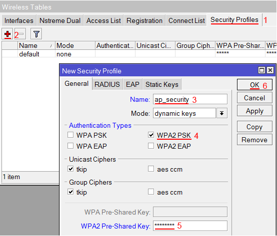
- Открываем вкладку Security Profiles;
- Нажимаем кнопку Add (плюсик);
- В новом окне в поле Name указываем имя профиля безопасности;
- Для лучшей безопасности оставляем только регистрацию по протоколу WPA2 PSK;
- В поле WPA2 Pre-Shared Key вводим пароль для доступа к Wi-Fi точке;
- Для сохранения настроек нажимаем кнопку OK.
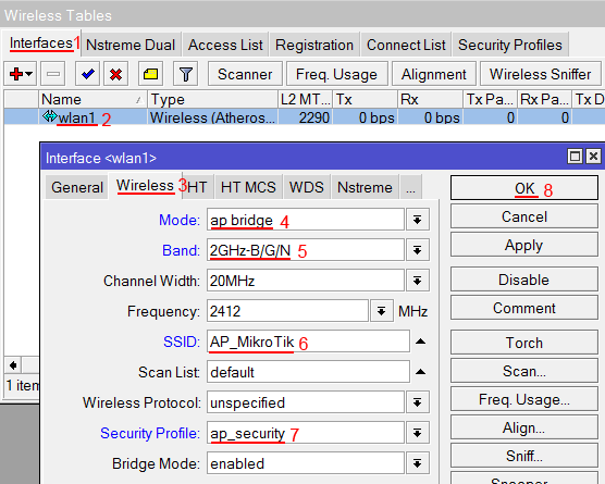
Настраиваем параметры Wi-Fi точки MikroTik:
- Открываем вкладку Interfaces;
- Делаем двойной клик кнопкой мыши на Wi-Fi интерфейсе wlan1, чтобы зайти в его настройки;
- Переходим на вкладку Wireless;
- В списке Mode выбираем режим работы ap bridge (точка доступа в режиме моста);
- В списке Band выбираем в каких стандартах будет работать Wi-Fi точка, мы выбрали B/G/N;
- В поле SSID прописываем имя точки доступа;
- В списке Security Profile выбираем имя профиля безопасности, в котором мы создавали пароль для доступа к Wi-Fi точке;
- Нажимаем кнопку OK для сохранения настроек.

Теперь можно подключаться к роутеру по Wi-Fi.
На компьютерах, подключенных к роутеру MikroTik по Wi-Fi, интернет не будет работать, пока вы не настроите Firewall и NAT.
Настройка Firewall и NAT
Чтобы компьютеры получали доступ к интернету, необходимо настроить Firewall и NAT на роутере MikroTik.
Откройте меню New Terminal для ввода команд.
Настройка NAT выполняется следующими командами:
ip firewall nat add chain=srcnat out-interface=ether1 action=masquerade, где ether1 — это интерфейс, на который приходит интернет от провайдера. Для PPPoE соединений указывается название PPPoE интерфейса.
Настройки NAT достаточно, чтобы заработал интернет.
Protect router — команды для защиты роутера:
ip firewall filter add action=accept chain=input disabled=no protocol=icmp
ip firewall filter add action=accept chain=input connection-state=established disabled=no in-interface=ether1
ip firewall filter add action=accept chain=input connection-state=related disabled=no in-interface=ether1
ip firewall filter add action=drop chain=input disabled=no in-interface=ether1
Protect LAN — защита внутренней сети:
ip firewall filter add action=jump chain=forward disabled=no in-interface=ether1 jump-target=customer
ip firewall filter add action=accept chain=customer connection-state=established disabled=no
ip firewall filter add action=accept chain=customer connection-state=related disabled=no
ip firewall filter add action=drop chain=customer disabled=no
Назначаем типы интерфейсов для защиты внутренней сети (external — внешний, internal — внутренний LAN):
ip upnp interfaces add disabled=no interface=ether1 type=external
ip upnp interfaces add disabled=no interface=ether2 type=internal
ip upnp interfaces add disabled=no interface=ether3 type=internal
ip upnp interfaces add disabled=no interface=ether4 type=internal
ip upnp interfaces add disabled=no interface=ether5 type=internal
ip upnp interfaces add disabled=no interface=bridge-local type=internal
Изменение пароля доступа к роутеру MikroTik
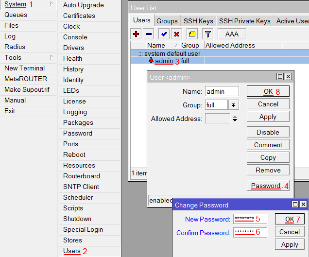
Чтобы изменить пароль доступа к роутеру MikroTik, выполните следующие действия:
- Открываем меню System;
- Выбираем Users;
- Делаем двойной клик кнопкой мыши на пользователе admin;
- Нажимаем кнопку Password…;
- В поле New Password вводим новый пароль;
- В поле Confirm Password подтверждаем новый пароль;
- В окне Change Password нажимаем кнопку OK;
- В окне User нажимаем кнопку OK.

Сброс роутера MikroTik к заводским настройкам
Чтобы сбросить MikroTik к заводским настройкам выполните следующее:
- Отключите питание роутера;
- Нажмите и держите кнопку Reset;
- Включите питание роутера;
- Дождитесь пока замигает индикатор ACT и отпустите кнопку Reset.

После этого роутер перезагрузится, и вы сможете зайти в его настройки со стандартным именем пользователя admin без пароля.
Если вы войдете в настройки с помощью программы Winbox, то появится следующее окно:
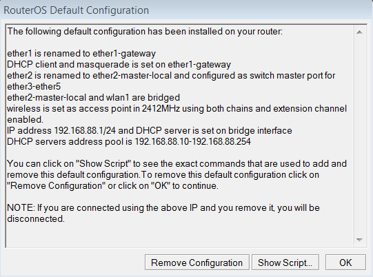
C помощью кнопки OK можно выполнить быструю настройку роутера по умолчанию.
Кнопка Remove Configuration позволяет сбросить все настройки для последующей ручной настройки роутера.
Теги
MikroTikWi-FiМаршрутизаторРоутерСетевое оборудование
Это инструкция, как пошагово настроить роутер MikroTik с нуля без использования заводской конфигурации.
Для настройки Wi-Fi роутера MikroTik нам понадобятся:
- кабель провайдера интернета (Triolan, MaxNet, Воля, Airbites, Vega или любые другие);
- компьютер или ноутбук с Wi-Fi;
- роутер MikroTik. Он будет раздавать Интернет по кабелю, а также по Wi-Fi на ноутбук, смартфон, телевизор с Wi-Fi или планшет.
Схема подключения роутера MikroTik:
- кабель провайдера интернета подключаем в первый порт роутера;
- компьютер подключаем к роутеру MikroTik сетевым кабелем в любой LAN порт от 2 до 5;
- ноутбук и другие беспроводные устройства подключим по Wi-Fi;
- блок питания включаем в разъем «Power» роутера MikroTik.
Настройка сетевой карты компьютера
Чтобы на компьютере можно было зайти в настройки роутера Mikrotik, настроим сетевую карту на получение автоматических настроек.
Открываем «Пуск» → «Панель управления» → «Центр управления сетями и общим доступом».

Перейдем в «Изменение параметров адаптера».

Нажимаем правой кнопкой мыши на «Подключение по локальной сети» и выбираем «Свойства»

Нажимаем на «Протокол Интернета версии 4 (TCP/IPv4)» и кнопку «Свойства».
Выбираем «Получить IP-адрес автоматически» и нажимаете кнопку «OK».
Если сетевая карта не получает автоматически IP адрес из подсети 192.168.88.x, попробуйте его указать вручную (например: 192.168.88.21) или сбросить роутер Mikrotik к заводским настройкам.
Вход в настройки роутера MikroTik
Выполнить настройку роутера MikroTik можно разными способами:
- С помощью специальной программы Winbox для ОС Windows. Скачать на официальном сайте.
- С помощью браузера, перейдя по адресу 192.168.88.1. В настройках браузера не должен быть указан proxy-сервер!
- Настройка через Telnet.
Мы будем настраивать роутер Mikrotik с помощью программы Winbox.
Подключаемся к роутеру MikroTik:
- Запустите программу Winbox и перейдите на вкладку Neighbors;
- В списке отобразится ваш роутер. Нажмите левой кнопкой мыши на его MAC адрес;
- Нажмите кнопку Connect.
Login по умолчанию admin, пароль пустой.

Сброс настроек роутера
Сбросим все настройки роутера MikroTik.
При первом входе у вас появится окно, как на картинке ниже. Нажмите кнопку Remove Configuration и дождитесь перезагрузки устройства.

Если у вас не появилось данное окно, сбросим настройки через меню:
- Выбираем слева меню System – Reset Configuration;
- Поставьте галочку No Default Configuration;
- Нажмите кнопку Reset Configuration.
- Нажмите кнопку Yes и дождитесь перезагрузки устройства.

Описание сетевых интерфейсов
Конфигурация сетевых интерфейсов MikroTik будет выглядеть следующим образом: первый порт ether1 будет подключен к провайдеру (WAN порт), остальные порты ether2-5 будут работать в режиме коммутатора для подключения компьютеров локальной сети.
Чтобы не путать сетевые интерфейсы, опишем их с помощью комментариев.
Входим в настройки MikroTik с помощью программы Winbox.
Записываем для первого порта ether1 комментарий “WAN”:
- Открываем меню Interfaces;
- Выбираем первый интерфейс ether1;
- Нажимаем желтую кнопку Comment;
- В появившемся окне вводим комментарий “WAN“;
- Нажимаем кнопку OK.

Записываем для второго порта ether2 комментарий “LAN”:
- Выбираем интерфейс ether2;
- Нажимаем желтую кнопку Comment;
- В появившемся окне вводим комментарий “LAN“;
- Нажимаем кнопку OK.

Теперь в списке интерфейсов четко видно их назначение.
Настройка WAN интерфейса MikroTik
Смена MAC адреса WAN порта
Если Ваш провайдер блокирует доступ к сети по MAC адресу, то необходимо сначала изменить MAC адрес WAN порта роутера MikroTik. В противном случае пропустите этот пункт.
Чтобы изменить MAC адрес порта MikroTik, открываем в программе Winbox меню New Terminal и вводим команду:
/interface ethernet set ether1 mac-address=00:01:02:03:04:05
, где ether1 – имя WAN интерфейса, 00:01:02:03:04:05 – разрешенный MAC адрес.

Чтобы вернуть родной MAC адрес порта, нужно выполнить команду:
/interface ethernet reset-mac ether1
, где ether1 – имя интерфейса.

Настройка Dynamic IP
Если интернет провайдер выдает Вам сетевые настройки автоматически, то необходимо настроить WAN порт роутера MikroTik на получение настроек по DHCP:
- Открываем меню IP;
- Выбираем DHCP Client;
- В появившемся окне нажимаем кнопку Add (плюсик);
- В новом окне в списке Interface: выбираем WAN интерфейс ether1;
- Нажимаем кнопку OK для сохранения настроек.

Теперь мы получили IP адрес от провайдера, который отображается в столбце IP Adress.

Проверим, что есть связь с интернетом:
- Открываем меню New Terminal;
- В терминале пишем команду ping 8.8.8.8 (пингуем сайт google) и жмем Enter на клавиатуре.
Как видим, идут пинги по 60ms, значит интернет подключен и работает. Остановить выполнение команды можно комбинацией клавиш на клавиатуре Ctrl+C.

На компьютерах, подключенных к роутеру MikroTik, интернет не будет работать, пока вы не настроите локальную сеть, Firewall и NAT.
Настройка Static IP
Если вы используете статические сетевые настройки, необходимо настроить WAN порт роутера MikroTik вручную.
Настроим статический IP адрес и маску подсети WAN порта MikroTik :
- Открываем меню IP;
- Выбираем Addresses;
- В появившемся окне нажимаем кнопку Add (плюсик);
- В новом окне в поле Address: прописываем статический IP адрес / маску подсети;
- В списке Interface: выбираем WAN интерфейс ether1;
- Для сохранения настроек нажимаем кнопку OK.

Настроим адрес интернет шлюза MikroTik:
- Открываем меню IP;
- Выбираем Routes;
- В появившемся окне нажимаем кнопку Add (плюсик);
- В новом окне в поле Gateway: прописываем IP адрес шлюза;
- Нажимаем кнопку OK для сохранения настроек.
Добавим адреса DNS серверов MikroTik:
- Открываем меню IP;
- Выбираем DNS;
- В появившемся окне нажимаем кнопку Settings;
- В новом окне в поле Servers: прописываем IP адрес предпочитаемого DNS сервера;
- Нажимаем кнопку “вниз” (черный треугольник), чтобы добавить еще одно поле для ввода;
- В новом поле прописываем IP адрес альтернативного DNS сервера;
- Ставим галочку Allow Remote Requests;
- Нажимаем кнопку OK для сохранения настроек.

Проверим, что есть доступ к интернету:
- Открываем меню New Terminal;
- В терминале пишем команду ping 8.8.8.8 (пингуем сайт google) и жмем Enter на клавиатуре.
Как видим, идут пинги по 60ms, значит интернет подключен и работает. Остановить выполнение команды можно комбинацией клавиш на клавиатуре Ctrl+C.
На компьютерах, подключенных к роутеру MikroTik, интернет не будет работать, пока вы не настроите локальную сеть, Firewall и NAT.
Настройка PPPoE
Если вы используете ADSL модем, к которому по сетевому кабелю подключен роутер MikroTik, сначала необходимо настроить ADSL модем в режим Bridge (мост).
Настроим клиентское PPPoE соединение на роутере MikroTik:
- Слева выбираем меню PPP;
- Нажимаем кнопку Add (плюсик);
- Выбираем PPPoE Client.

Настраиваем параметры PPPoE соединения MikroTik:
- В поле Name указываем имя соединения;
- В списке Interfaces выбираем первый WAN порт ether1, который подключен к провайдеру;
- Переходим на вкладку Dial Out;
- В поле User указываем имя пользователя;
- В поле Password вводим пароль;
- Ставим галочку Use Peer DNS;
- Нажимаем кнопку OK.


После создания PPPoE соединения напротив него должна появиться буква R, которая говорит о том, что соединение установлено.
Проверим, что есть связь с интернетом:
- Открываем меню New Terminal;
- В терминале пишем команду ping 8.8.8.8 (пингуем сайт google) и жмем Enter на клавиатуре.
Как видим, идут пинги по 60ms, значит интернет подключен и работает. Остановить выполнение команды можно комбинацией клавиш на клавиатуре Ctrl+C.
На компьютерах, подключенных к роутеру MikroTik, интернет не будет работать, пока вы не настроите локальную сеть, Firewall и NAT.
Настройка локальной сети MikroTik
Объединение Wi-Fi и проводных интерфейсов в локальную сеть
Чтобы компьютеры, подключенные к роутеру по кабелю и по Wi-Fi, друг друга «видели», необходимо объединить беспроводной и проводные интерфейсы MikroTik. Если у вас роутер без Wi-Fi, то объединяете только проводные интерфейсы.
Создаем объединение bridge-local (мост);
- Открываем меню Bridge;
- Нажимаем кнопку Add (плюсик);
- В поле Name прописываем имя объединения bridge-local;
- Нажимаем кнопку OK.
Добавляем в объединение проводные ethetnet порты 2-5:
- Переходим на вкладку Ports;
- Нажимаем кнопку Add (плюсик);
- В списке Interface выбираем ethernet порт ether2;
- В списке Bridge выбираем имя объединения bridge-local;
- Нажимаем кнопку OK;
- Точно так же добавляем порты ether3, ether4, ether5.

Добавляем в объединение Wi-Fi интерфейс.
- Переходим на вкладку Ports;
- Нажимаем кнопку Add (плюсик);
- В списке Interface выбираем беспроводной интерфейс wlan1;
- В списке Bridge выбираем имя объединения bridge-local;
- Нажимаем кнопку OK.
Назначение IP адреса локальной сети
Настроим IP адрес локальной сети MikroTik:
- Открываем меню IP;
- Выбираем Addresses;
- Нажимаем кнопку Add (плюсик);
- В поле Address вводим адрес и маску локальной сети, например 192.168.88.1/24;
- В списке Interface выбираем bridge-local;
- Нажимаем кнопку OK.

Настройка DHCP сервера
Чтобы компьютеры, подключенные к роутеру, получали сетевые настройки автоматически, настроим DHCP сервер MikroTik:
- Открываем меню IP;
- Выбираем DHCP Server;
- Нажимаем кнопку DHCP Setup;
- В списке DHCP Server Interface выбираем bridge-local;
- Нажимаем кнопку Next;
- В этом окне выбирается сеть для DHCP. Оставляем без изменений и нажимаем кнопку Next;
- В следующем окне указывается адрес шлюза. Нажимаем кнопку Next;
- В этом окне прописывается диапазон IP адресов, которые будет раздавать DHCP сервер. Нажимаем кнопку Next;
- Далее вводятся адреса DNS серверов. Нажимаем кнопку Next;
- Здесь задается время резервирования IP адресов. Нажимаем кнопку Next;
- Настройка DHCP сервера успешно завершена. Жмем кнопку OK.


Теперь сетевой кабель компьютера отключаем от роутера и еще раз подключаем к нему.
Настройка Wi-Fi точки доступа MikroTik
Сначала необходимо включить Wi-Fi модуль:
- Открываем меню Wireless;
- Выбираем Wi-Fi интерфейс wlan1;
- Нажимаем кнопку Enable (синяя галочка).

Создаем пароль для подключения к точке доступа MikroTik:
- Открываем вкладку Security Profiles;
- Нажимаем кнопку Add (плюсик);
- В новом окне в поле Name: указываем имя профиля безопасности;
- Для лучшей безопасности оставляем только регистрацию по протоколу WPA2 PSK;
- В поле WPA2 Pre-Shared Key вводим пароль для доступа к Wi-Fi точке;
- Для сохранения настроек нажимаем кнопку OK.

Настраиваем параметры Wi-Fi точки MikroTik:
- Открываем вкладку Interfaces;
- Делаем двойной клик кнопкой мыши на Wi-Fi интерфейсе wlan1, чтобы зайти в его настройки;
- Переходим на вкладку Wireless;
- В списке Mode: выбираем режим работы ap bridge (точка доступа в режиме моста);
- В списке Band: выбираем в каких стандартах будет работать Wi-Fi точка, мы выбрали B/G/N;
- В поле SSID: прописываем имя точки доступа;
- В списке Security Profile выбираем имя профиля безопасности, в котором мы создавали пароль для доступа к Wi-Fi точке;
- Нажимаем кнопку OK для сохранения настроек.
Теперь можно подключаться к роутеру по Wi-Fi.
На компьютерах, подключенных к роутеру MikroTik по Wi-Fi, интернет не будет работать, пока вы не настроите Firewall и NAT.
Настройка Firewall и NAT
Чтобы компьютеры получали доступ к интернету, необходимо настроить Firewall и NAT на роутере MikroTik.
Откройте меню New Terminal для ввода команд.
Настройка NAT выполняется следующими командами:
ip firewall nat add chain=srcnat out-interface=ether1 action=masquerade
, где ether1 – это интерфейс, на который приходит интернет от провайдера. Для PPPoE соединений указывается название PPPoE интерфейса.
Настройки NAT достаточно, чтобы заработал интернет.
Protect router – команды для защиты роутера:
ip firewall filter add action=accept chain=input disabled=no protocol=icmp
ip firewall filter add action=accept chain=input connection-state=established disabled=no in-interface=ether1
ip firewall filter add action=accept chain=input connection-state=related disabled=no in-interface=ether1
ip firewall filter add action=drop chain=input disabled=no in-interface=ether1
Protect LAN – защита внутренней сети:
ip firewall filter add action=jump chain=forward disabled=no in-interface=ether1 jump-target=customer
ip firewall filter add action=accept chain=customer connection-state=established disabled=no
ip firewall filter add action=accept chain=customer connection-state=related disabled=no
ip firewall filter add action=drop chain=customer disabled=no
Назначаем типы интерфейсов для защиты внутренней сети (external – внешний, internal – внутренний LAN):
ip upnp interfaces add disabled=no interface=ether1 type=external
ip upnp interfaces add disabled=no interface=ether2 type=internal
ip upnp interfaces add disabled=no interface=ether3 type=internal
ip upnp interfaces add disabled=no interface=ether4 type=internal
ip upnp interfaces add disabled=no interface=ether5 type=internal
ip upnp interfaces add disabled=no interface=bridge-local type=internal
Изменение пароля доступа к роутеру MikroTik
Чтобы изменить пароль доступа к роутеру MikroTik, выполните следующие действия:
- Открываем меню System;
- Выбираем Users;
- Делаем двойной клик кнопкой мыши на пользователе admin;
- Нажимаем кнопку Password…;
- В поле New Password вводим новый пароль;
- В поле Confirm Password подтверждаем новый пароль;
- В окне Change Password нажимаем кнопку OK;
- В окне User нажимаем кнопку OK.
Сброс роутера MikroTik к заводским настройкам
Чтобы сбросить MikroTik к заводским настройкам выполните следующее:
- Отключите питание роутера;
- Нажмите и держите кнопку Reset;
- Включите питание роутера;
- Дождитесь пока замигает индикатор ACT и отпустите кнопку Reset.
После этого роутер перезагрузится, и вы сможете зайти в его настройки со стандартным именем пользователя admin без пароля.
Если вы войдете в настройки с помощью программы Winbox, то появится следующее окно:

C помощью кнопки OK можно выполнить быструю настройку роутера по умолчанию.
Кнопка Remove Configuration позволяет сбросить все настройки для последующей ручной настройки роутера.
Как настроить Mikrotik самому
Это инструкция, как пошагово настроить роутер MikroTik с нуля без использования заводской конфигурации.
Подключение роутера MikroTik
Для настройки Wi-Fi роутера MikroTik нам понадобятся:
-
кабель провайдера интернета (Megaline, Homeline, Aknet или любые другие);
-
компьютер или ноутбук с Wi-Fi;
-
Роутер Mirkotik (в нашем случае RB751U-2HnD). Он будет раздавать Интернет по кабелю, а также по Wi-Fi на ноутбук, смартфон, телевизор с Wi-Fi или планшет.
Схема подключения роутера MikroTik:
-
кабель провайдера интернета подключаем в первый порт роутера;
-
компьютер подключаем к роутеру MikroTik сетевым кабелем в любой LAN порт от 2 до 5;
-
ноутбук и другие беспроводные устройства подключим по Wi-Fi;
-
блок питания включаем в разъем «Power» роутера MikroTik.

Настройка сетевой карты компьютера
Чтобы на компьютере можно было зайти в настройки роутера Mikrotik, настроим сетевую карту на получение автоматических настроек.
Открываем «Пуск» → «Панель управления» → «Центр управления сетями и общим доступом».
Перейдем в «Изменение параметров адаптера».

Нажимаем правой кнопкой мыши на «Подключение по локальной сети» и выбираем «Свойства»
Нажимаем на «Протокол Интернета версии 4 (TCP/IPv4)» и кнопку «Свойства».

Выбираем «Получить IP-адрес автоматически» и нажимаете кнопку «OK».

Если сетевая карта не получает автоматически IP адрес из подсети 192.168.88.x, попробуйте его указать вручную (например: 192.168.88.21)
Вход в настройки роутера MikroTik
Выполнить настройку роутера MikroTik можно разными способами:
-
С помощью специальной программы Winbox для ОС Windows. Скачать на официальном сайте.
-
С помощью браузера, перейдя по адресу 192.168.88.1. В настройках браузера не должен быть указан proxy-сервер!
Мы будем настраивать роутер Mikrotik с помощью программы Winbox.
Подключаемся к роутеру MikroTik:
-
Запустите программу Winbox и перейдите на вкладку Neighbors;
-
В списке отобразится ваш роутер. Нажмите левой кнопкой мыши на его MAC адрес;
-
Нажмите кнопку Connect.
Login по умолчанию admin, пароль пустой.

Сброс настроек роутера
Сбросим все настройки роутера MikroTik.
При первом входе у вас появится окно, как на картинке ниже. Нажмите кнопку Remove Configuration и дождитесь перезагрузки устройства.

Если у вас не появилось данное окно, сбросим настройки через меню:
-
Выбираем слева меню System — Reset Configuration;
-
Поставьте галочку No Default Configuration;
-
Нажмите кнопку Reset Configuration.
-
Нажмите кнопку Yes и дождитесь перезагрузки устройства.

Описание сетевых интерфейсов
Конфигурация сетевых интерфейсов MikroTik будет выглядеть следующим образом: первый порт ether1 будет подключен к провайдеру (WAN порт), остальные порты ether2-5 будут работать в режиме коммутатора для подключения компьютеров локальной сети.
Чтобы не путать сетевые интерфейсы, опишем их с помощью комментариев.
Входим в настройки MikroTik с помощью программы Winbox.
Записываем для первого порта ether1 комментарий «WAN»:
-
Открываем меню Interfaces;
-
Выбираем первый интерфейс ether1;
-
Нажимаем желтую кнопку Comment;
-
В появившемся окне вводим комментарий «WAN«;
-
Нажимаем кнопку OK.

Записываем для второго порта ether2 комментарий «LAN»:
-
Выбираем интерфейс ether2;
-
Нажимаем желтую кнопку Comment;
-
В появившемся окне вводим комментарий «LAN«;
-
Нажимаем кнопку OK.
Теперь в списке интерфейсов четко видно их назначение.

Настройка WAN интерфейса MikroTik
Смена MAC адреса WAN порта
Если Ваш провайдер блокирует доступ к сети по MAC адресу, то необходимо сначала изменить MAC адрес WAN порта роутера MikroTik. В противном случае пропустите этот пункт.
Чтобы изменить MAC адрес порта MikroTik, открываем в программе Winbox меню New Terminal и вводим команду:
/interface ethernet set ether1 mac-address=00:01:02:03:04:05
, где ether1 — имя WAN интерфейса, 00:01:02:03:04:05 — разрешенный MAC адрес.
![]()
Чтобы вернуть родной MAC адрес порта, нужно выполнить команду:
/interface ethernet reset-mac ether1
, где ether1 — имя интерфейса.
![]()
Настройка Dynamic IP
Если интернет провайдер выдает Вам сетевые настройки автоматически, то необходимо настроить WAN порт роутера MikroTik на получение настроек по DHCP:
-
Открываем меню IP;
-
Выбираем DHCP Client;
-
В появившемся окне нажимаем кнопку Add (плюсик);
-
В новом окне в списке Interface: выбираем WAN интерфейс ether1;
-
Нажимаем кнопку OK для сохранения настроек.
Теперь мы получили IP адрес от провайдера, который отображается в столбце IP Adress.
Проверим, что есть связь с интернетом:
-
Открываем меню New Terminal;
-
В терминале пишем команду ping 8.8.8.8 (пингуем сайт google) и жмем Enter на клавиатуре.
Как видим, идут пинги по 60ms, значит интернет подключен и работает. Остановить выполнение команды можно комбинацией клавиш на клавиатуре Ctrl+C.

На компьютерах, подключенных к роутеру MikroTik, интернет не будет работать, пока вы не настроите локальную сеть, Firewall и NAT.
Настройка Static IP
Если вы используете статические сетевые настройки, необходимо настроить WAN порт роутера MikroTik вручную.
Настроим статический IP адрес и маску подсети WAN порта MikroTik :
-
Открываем меню IP;
-
Выбираем Addresses;
-
В появившемся окне нажимаем кнопку Add (плюсик);
-
В новом окне в поле Address: прописываем статический IP адрес / маску подсети;
-
В списке Interface: выбираем WAN интерфейс ether1;
-
Для сохранения настроек нажимаем кнопку OK.
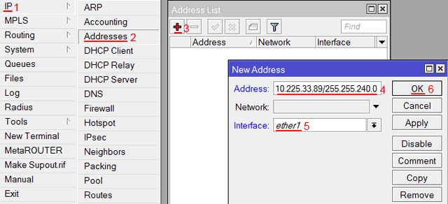
Настроим адрес интернет шлюза MikroTik:
-
Открываем меню IP;
-
Выбираем Routes;
-
В появившемся окне нажимаем кнопку Add (плюсик);
-
В новом окне в поле Gateway: прописываем IP адрес шлюза;
-
Нажимаем кнопку OK для сохранения настроек.

Добавим адреса DNS серверов MikroTik:
-
Открываем меню IP;
-
Выбираем DNS;
-
В появившемся окне нажимаем кнопку Settings;
-
В новом окне в поле Servers: прописываем IP адрес предпочитаемого DNS сервера;
-
Нажимаем кнопку «вниз» (черный треугольник), чтобы добавить еще одно поле для ввода;
-
В новом поле прописываем IP адрес альтернативного DNS сервера;
-
Ставим галочку Allow Remote Requests;
-
Нажимаем кнопку OK для сохранения настроек.

Проверим, что есть доступ к интернету:
-
Открываем меню New Terminal;
-
В терминале пишем команду ping 8.8.8.8 (пингуем сайт google) и жмем Enter на клавиатуре.
Как видим, идут пинги по 60ms, значит интернет подключен и работает. Остановить выполнение команды можно комбинацией клавиш на клавиатуре Ctrl+C.

На компьютерах, подключенных к роутеру MikroTik, интернет не будет работать, пока вы не настроите локальную сеть, Firewall и NAT.
Настройка PPPoE
Если вы используете ADSL модем, к которому по сетевому кабелю подключен роутер MikroTik, сначала необходимо настроить ADSL модем в режим Bridge (мост).
Настроим клиентское PPPoE соединение на роутере MikroTik:
-
Слева выбираем меню PPP;
-
Нажимаем кнопку Add (плюсик);
-
Выбираем PPPoE Client.
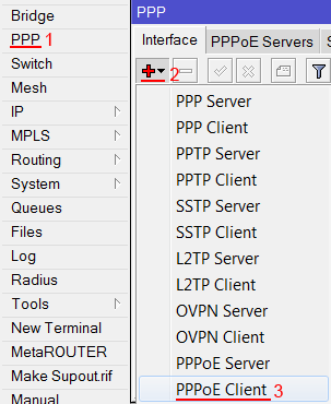
Настраиваем параметры PPPoE соединения MikroTik:
-
В поле Name указываем имя соединения;
-
В списке Interfaces выбираем первый WAN порт ether1, который подключен к провайдеру;

-
Переходим на вкладку Dial Out;
-
В поле User указываем имя пользователя;
-
В поле Password вводим пароль;
-
Ставим галочку Use Peer DNS;
-
Нажимаем кнопку OK.
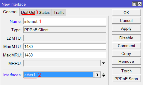
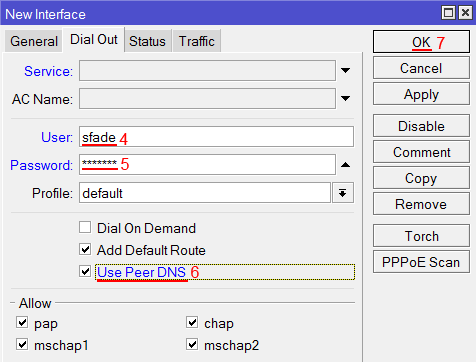
После создания PPPoE соединения напротив него должна появиться буква R, которая говорит о том, что соединение установлено.

Проверим, что есть связь с интернетом:
-
Открываем меню New Terminal;
-
В терминале пишем команду ping 8.8.8.8 (пингуем сайт google) и жмем Enter на клавиатуре.
Как видим, идут пинги по 60ms, значит интернет подключен и работает. Остановить выполнение команды можно комбинацией клавиш на клавиатуре Ctrl+C.

На компьютерах, подключенных к роутеру MikroTik, интернет не будет работать, пока вы не настроите локальную сеть, Firewall и NAT.
Настройка локальной сети MikroTik
Чтобы компьютеры, подключенные к роутеру по кабелю и по Wi-Fi, друг друга «видели», необходимо объединить беспроводной и проводные интерфейсы MikroTik. Если у вас роутер без Wi-Fi, то объединяете только проводные интерфейсы.
Создаем объединение bridge-local (мост);
-
Открываем меню Bridge;
-
Нажимаем кнопку Add (плюсик);
-
В поле Name прописываем имя объединения bridge-local;
-
Нажимаем кнопку OK.

Добавляем в объединение проводные ethetnet порты 2-5:
-
Переходим на вкладку Ports;
-
Нажимаем кнопку Add (плюсик);
-
В списке Interface выбираем ethernet порт ether2;
-
В списке Bridge выбираем имя объединения bridge-local;
-
Нажимаем кнопку OK;
-
Точно так же добавляем порты ether3, ether4, ether5.
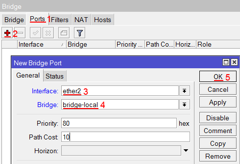
Добавляем в объединение Wi-Fi интерфейс.
-
Переходим на вкладку Ports;
-
Нажимаем кнопку Add (плюсик);
-
В списке Interface выбираем беспроводной интерфейс wlan1;
-
В списке Bridge выбираем имя объединения bridge-local;
-
Нажимаем кнопку OK.

Назначение IP адреса локальной сети
Настроим IP адрес локальной сети MikroTik:
-
Открываем меню IP;
-
Выбираем Addresses;
-
Нажимаем кнопку Add (плюсик);
-
В поле Address вводим адрес и маску локальной сети, например 192.168.88.1/24;
-
В списке Interface выбираем bridge-local;
-
Нажимаем кнопку OK.

Настройка DHCP сервера
Чтобы компьютеры, подключенные к роутеру, получали сетевые настройки автоматически, настроим DHCP сервер MikroTik:
-
Открываем меню IP;
-
Выбираем DHCP Server;
-
Нажимаем кнопку DHCP Setup;

-
В списке DHCP Server Interface выбираем bridge-local;
-
Нажимаем кнопку Next;

-
В этом окне выбирается сеть для DHCP. Оставляем без изменений и нажимаем кнопку Next;

-
В следующем окне указывается адрес шлюза. Нажимаем кнопку Next;

-
В этом окне прописывается диапазон IP адресов, которые будет раздавать DHCP сервер. Нажимаем кнопку Next;

-
Далее вводятся адреса DNS серверов. Нажимаем кнопку Next;

-
Здесь задается время резервирования IP адресов. Нажимаем кнопку Next;

-
Настройка DHCP сервера успешно завершена. Жмем кнопку OK.


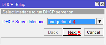
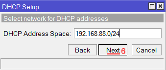

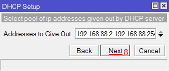


Теперь сетевой кабель компьютера отключаем от роутера и еще раз подключаем к нему.
Настройка Wi-Fi точки доступа MikroTik
Сначала необходимо включить Wi-Fi модуль:
-
Открываем меню Wireless;
-
Выбираем Wi-Fi интерфейс wlan1;
-
Нажимаем кнопку Enable (синяя галочка).

Создаем пароль для подключения к точке доступа MikroTik:
-
Открываем вкладку Security Profiles;
-
Нажимаем кнопку Add (плюсик);
-
В новом окне в поле Name: указываем имя профиля безопасности;
-
Для лучшей безопасности оставляем только регистрацию по протоколу WPA2 PSK;
-
В поле WPA2 Pre-Shared Key вводим пароль для доступа к Wi-Fi точке;
-
Для сохранения настроек нажимаем кнопку OK.

Настраиваем параметры Wi-Fi точки MikroTik:
-
Открываем вкладку Interfaces;
-
Делаем двойной клик кнопкой мыши на Wi-Fi интерфейсе wlan1, чтобы зайти в его настройки;
-
Переходим на вкладку Wireless;
-
В списке Mode: выбираем режим работы ap bridge (точка доступа в режиме моста);
-
В списке Band: выбираем в каких стандартах будет работать Wi-Fi точка, мы выбрали B/G/N;
-
В поле SSID: прописываем имя точки доступа;
-
В списке Security Profile выбираем имя профиля безопасности, в котором мы создавали пароль для доступа к Wi-Fi точке;
-
Нажимаем кнопку OK для сохранения настроек.

Теперь можно подключаться к роутеру по Wi-Fi.
На компьютерах, подключенных к роутеру MikroTik по Wi-Fi, интернет не будет работать, пока вы не настроите Firewall и NAT.
Настройка Firewall и NAT
Чтобы компьютеры получали доступ к интернету, необходимо настроить Firewall и NAT на роутере MikroTik.
Откройте меню New Terminal для ввода команд.
Настройка NAT выполняется следующими командами:
ip firewall nat add chain=srcnat out-interface=ether1 action=masquerade
, где ether1 — это интерфейс, на который приходит интернет от провайдера. Для PPPoE соединений указывается название PPPoE интерфейса.
Настройки NAT достаточно, чтобы заработал интернет.
Protect router — команды для защиты роутера:
ip firewall filter add action=accept chain=input disabled=no protocol=icmp
ip firewall filter add action=accept chain=input connection-state=established disabled=no in-interface=ether1
ip firewall filter add action=accept chain=input connection-state=related disabled=no in-interface=ether1
ip firewall filter add action=drop chain=input disabled=no in-interface=ether1
Protect LAN — защита внутренней сети:
ip firewall filter add action=jump chain=forward disabled=no in-interface=ether1 jump-target=customer
ip firewall filter add action=accept chain=customer connection-state=established disabled=no
ip firewall filter add action=accept chain=customer connection-state=related disabled=no
ip firewall filter add action=drop chain=customer disabled=no
Назначаем типы интерфейсов для защиты внутренней сети (external — внешний, internal — внутренний LAN):
ip upnp interfaces add disabled=no interface=ether1 type=external
ip upnp interfaces add disabled=no interface=ether2 type=internal
ip upnp interfaces add disabled=no interface=ether3 type=internal
ip upnp interfaces add disabled=no interface=ether4 type=internal
ip upnp interfaces add disabled=no interface=ether5 type=internal
ip upnp interfaces add disabled=no interface=bridge-local type=internal
Изменение пароля доступа к роутеру MikroTik
Чтобы изменить пароль доступа к роутеру MikroTik, выполните следующие действия:
-
Открываем меню System;
-
Выбираем Users;
-
Делаем двойной клик кнопкой мыши на пользователе admin;
-
Нажимаем кнопку Password…;
-
В поле New Password вводим новый пароль;
-
В поле Confirm Password подтверждаем новый пароль;
-
В окне Change Password нажимаем кнопку OK;
-
В окне User нажимаем кнопку OK.

Сброс роутера MikroTik к заводским настройкам
Чтобы сбросить MikroTik к заводским настройкам выполните следующее:
-
Отключите питание роутера;
-
Нажмите и держите кнопку Reset;
-
Включите питание роутера;
-
Дождитесь пока замигает индикатор ACT и отпустите кнопку Reset.

После этого роутер перезагрузится, и вы сможете зайти в его настройки со стандартным именем пользователя admin без пароля.
Если вы войдете в настройки с помощью программы Winbox, то появится следующее окно:

C помощью кнопки OK можно выполнить быструю настройку роутера по умолчанию.
Кнопка Remove Configuration позволяет сбросить все настройки для последующей ручной настройки роутера.